1
Read Me First
for the HP ProCurve Routing Switches 9304M, 9308M, and 6308M-SX
and the HP ProCurve Switch 6208M-SX
Covering Software Release 05.2.14 (or Later)
Contents:
■
■
■
■
■
■
■
Software Updates Are Free!
New Software Release 05.2.14
Module Installation
Getting Started
Your Free Ticket to Proactive Networking
Accessory Parts List
Operating Notes, Troubleshooting, and Errata
Warning: Do not use the handles on the power supply
units to lift or carry the routing switch.
Software Updates Are Free!
Help Us Help You...Register Now To Keep Up-To-Date on the Latest Software!
Hewlett-Packard provides free software updates for all managed HP ProCurve networking products. To access
the software updates, to to the HP ProCurve website at http://www.hp.com/go/procurve, then click on Free
Software Updates.
Register for Automatic Notification of Updates. From the Free Software Updates page you can also
register yourself to automatically receive email notice of new updates for your managed HP ProCurve
networking products. Just follow the instructions on that page for how to receive the update notices.
To determine whether you have the latest software, compare the software version that is available on the website with the
version that is currently installed in your switch or routing switch. To load a new software image, see chapter 4, "Updating
Software Images and Configuration Files", in the manual you received with the switch or routing switch.
Note that current product documentation, plus any supplements describing how to use any recently released software
updates are also available on the above website (click on Technical Support, then Manual).
New Software Release 05.2.14 (or Later) Is Now Available with the Following
New Features
• Support for Redundant Management Modules
– Increased Default Maximum Number of IP Routes
– Larger Default Maximum Number of BGP4 Neighbor Prefixes
• Single-Instance Spanning Tree
• Enhanced show tech command
• Faster BGP4 route update convergence time
• SNMP and Syslog Message Enhancements
• More Layer 2, Layer 3, and System Level Enhancements
• Software Fixes
For more information, refer to the documentation shipped with the switch or routing switch, or to Release Notes for
Version 05.2.14 of the HP ProCurve Routing Switches 9304M, 9308M, and 6308M-SX, and the HP ProCurve Switch
6208M-SX Operating System. This booklet is available on HP’s ProCurve website at http://www.hp.com/go/procurve
(click on Technical Support, then Manual).
Module Installation
C a u ti o n — R o u ti n g S w it c h 9 3 0 4 M a n d 9 30 8 M
To avoid hardware damage during module installation, be careful to properly line up the edges of the module
board with the guides built into the module slot on the chassis.
Getting Started
You can initially access the routing switch in either of the following ways:
■
Via Telnet or FTP through port 1 on the management module, using the factory default IP address (209.157.22.254)
and subnet mask (255.255.255.0)
■
By connecting a terminal device to the serial port on the management module
Note: HP recommends that you use the console cable provided with the routing switch. If you need to use a different
cable, please see the "Console Cable" entry under "Accessory Parts List" on the next page.
After you have accessed the routing switch, change the default IP address and subnet mask to correspond to your network’s
addressing scheme. For more on assigning an IP address and other topics, see the following:
Topic
Location in the Installation
and Configuration Guide
Installation Procedures and Precautions
Chapter 2
Attaching a Terminal Device and Assigning an IP Chapter 2
Address
Using Redundant Management Modules
Chapter 3
System Boot from a Bootp Server
Appendix B
Software Overview
Chapter 5
Hardware Overview and Specifications
Chapter 6
Enabling Telnet
Chapters 2 (pp. 2-28, 2-29) and 5 (p. 5-9)
Your Free Ticket to Proactive Networking!
HP TopTools for Switches & Hubs is a breakthrough in network management software that gives you more network with
less work. The TopTools for Switches & Hubs CD is included at no extra charge with your HP ProCurve routing switch. See
the system requirements printed on the sleeve containing the HP TopTools CD.
2
Accessory Parts List
The following accessories are included with your HP ProCurve routing switch.
Item
Notes
Power Cord Kit
The HP ProCurve 9304M: Either three power cords (one each for the U.S.A., the U.K., and continental Europe) or
one power cord for Australia.
The HP ProCurve 9308M: Either six power cords (two each for the U.S.A., the U.K., and continental Europe) or two
power cords for Australia.
The HP ProCurve 6308M-SX: Two power cords for either the U.S.A., continental Europe, Australia, or the UK.
The HP ProCurve 6208M-SX: Two power cords for either the U.S.A., continental Europe, Australia, or the UK.
Caution: If the installation requires a different power cord than the one supplied with the switch or routing switch,
be sure to use a shielded power cord displaying the mark of the safety agency that defines the regulations for
power cords in your country. The mark is your assurance that the power cord can be used safely with the switch
or routing switch.
Console Cable
Connects terminal, PC, or modem to serial port on any HP 9300 management module, 6308M-SX routing switch,
or 6208M-SX switch for direct-connect or modem access management using the Command Line Interface (CLI),
or console. If you need to use a different cable, select a "straight-through" serial cable with a female DB-9 to DB9 connector for the connection to the switch or routing switch. For more information, see "Attaching a PC or
Terminal" in chapter 2, "Installation".
Rack Mount Kit
Contains two mounting brackets and the screws required to attach the brackets to the switch or routing switch.
HP TopTools for Switches
& Hubs CD
For system requirements, see the sleeve containing the CD.
Product Documentation
• Installation and Getting Started Guide
• Product Documentation CD-ROM
• Release Notes and Manual Supplements describing software features (if any) added after the last revision of
the manuals (For the latest information, go to http://www.hp.com/go/procurve, click on Technical Support,
and then click on Manual.)
• Declaration of Conformity (for product shipments in Europe)
Warranty Booklet
—
Operating Notes, Troubleshooting, and Errata
Redundant Management Module Operation
When two redundant management modules are installed in an HP 9304M or 9308M Routing Switch, the two modules
work together as active and standby management modules. If the active module becomes unavailable, the standby
module automatically takes over system operation. If this occurs, the routing tables, ARP tables, etc. are all updated
dynamically, as if the routing switch had been rebooted. As a result of this reconvergence, a noticeable, temporary
network disruption will occur. The duration of the disruption depends on the number of routes being utilized through
the device, and can be significant.
Default Spanning Tree Protocol (STP) Settings
Pages 5-12 and 8-31 in Book 1: Installation and Getting Started Guide, and page 17-7 in Book 2: Advanced
Configuration and Management Guide, incorrectly state that STP is enabled by default on the HP 6208M Switch.
The default STP setting for the 6208M switch as well as the 9304M, 9308M, and 6308M routing switches is "disabled".
On all of these devices, STP must be enabled at the system level to allow assignment of this capability to the VLAN
level. For more information on STP, see:
■
The next topic, "Configuring Single-Instance Spanning Tree Protocol (STP)" on page 4.
3
■
"Enabling or Disabling Spanning Tree Protocol (STP)" on page 8-31 in Book 1: Installation and Getting
Started, that was shipped with your device
■
Book 2: Advanced Configuration and Management (included on the Product Documentation CD-ROM
shipped with your device):
•
"Spanning Tree Protocol" on page 17-7
•
"Enable Spanning Tree on a VLAN" on page 17-19
•
"spanning-tree" on page B-153
Configuring Single-Instance Spanning Tree Protocol (STP)
Beginning with software release 05.2.14, you can configure either single-instance or multiple-instance spanning tree
on the HP 9304M, 9308M, and 6308M-SX routing switches, and the HP 6208M-SX Switch. When single-instance STP is
enabled, all VLANS on the device belong to the same spanning tree VLAN—with a shared STP VLAN ID of 4094. When
multi-instance STP is used, each VLAN has a unique spanning tree ID.
To enable single-instance STP:
1.
Enable single-instance STP globally.
2.
Enable STP on each interface on which you want STP to operate.
•
On the 9304M, 9308M, and 6308M-SX routing switches, you can enable STP on a per port or per VLAN
basis.
•
On the 6208M switch, enabling single-instance STP initially applies to all VLANs in the switch. You can
use the no spanning tree command to disable STP on individual VLANs in the switch.
Example of Single-Instance STP Configuration: Beginning at the User EXEC level of the CLI, execute the
following:
HP9308>enable
HP9308#configure terminal
HP9308(config)#spanning-tree single Enables single-instance STP globally.
HP9308#wr mem
Saves the configuration change to memory.
Single instance STP must be enabled for each VLAN that participates in the
spanning-tree algorithm. The configuration file will show whether STP is enabled
for a specific VLAN. In the following example, VLAN 100 is configured for STP
(participating in the STP algorithm), while VLAN 101 is not.
HP9308(config)#vlan 100
HP9308(config-vlan-100)#span
HP9308(config)#wr mem
Continuing from above, this command enables single-instance STP on VLAN 100.
("100" is the <vlan ID>.)
Saves the configuration change to memory.
After executing the above commands, the show config command will list the following VLAN/STP information:
ver 05.2.1x
!
span single
!
vlan 100 by port
tagged ethe 3/1 to 3/2
span
!
vlan 101 by port
tagged ethe 3/1 to 3/2
no span
4
Shows the software version number for the device.
Indicates single-instance STP is enabled on the device.
"span" indicates single-instance STP is configured on VLAN 100.
(Note: on the 6208M-XS switch, the word "span" does not appear, even though the
device has been enabled for that VLAN.)
"no span" indicates that STP is not configured on VLAN 101.
When multiple-instance STP is enabled, if VLAN 100 uses STP and VLAN 101 does not, the configuration file generated
by show config shows the following:
ver 05.2.1x
!
global-stp
!
vlan 100 by port
tagged ethe 3/1 to 3/2
span
!
vlan 101 by port
tagged ethe 3/1 to 3/2
Shows the software version for the device.
Indicats that multiple-instance STP is enabled on the device.
In the case of multiple-instance STP, the VLAN(s) on which STP is running are
indicated by the presence of span.
For more information on STP, see "Default Spanning Tree Protocol (STP) Settings" on page 3.
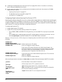
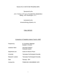
Implementing Spanning Tree Protocol (STP) in a Tagged VLAN Environment
Condition. The HP ProCurve 9304M, 9308M, and 6308M-SX routing switches and the 6208M-SX switch offer both
multiple-instance and single-instance spanning tree. The HP ProCurve 1600M, 2400M, 2424M, 4000M, and 8000M
switches use single-instance spanning tree only. In a network where multiple-instance STP is configured on a 9304M,
9308M, 6308M-SX, or 6208M-SX, STP will fail on a connection between any of these devices and a single-instance STP
device if the STP Priority parameter settings are left at their defaults. (In most cases, the 6308M-SX and 6208M-SX
would be used in the core network, and would not be configured for multiple-instance STP.) That is, if one or more
of the single-instance STP-enabled switches in the network uses the default STP Priority parameter setting (32768),
then one of these switches will become the root bridge (due the MAC addresses in these switches being lower than
the MAC addresses in the multiple-instance STP devices). When this occurs, STP fails on any links between the (root
bridge) switch and any multiple-instance STP device (9304M, 9308M, 6308M-SX, or 6208M-SX) to which the switch
is connected.
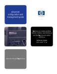
Switch 8000M
9308M
Routing Switch
STP enabled
(single instance)
STP enabled
(multiple instance)
Switch 8000M
STP enabled
(single instance)
For STP to operate properly in this example, the
9308M STP Priority parameter must be lower
than the Priority parameter setting in the Switch
8000Ms. (See "Solution", below.)
Solution. Interoperability testing indicates that the STP configuration allows for proper interoperation between a
9304M, 9308M, 6308M-SX, or 6208M-SX (configured for multiple-instance STP) and a 1600M, 2400M, 2424M, 4000M,
or 8000M switch in a tagged VLAN environment.
1.
On the 9304M, 9308M, 6308M-SX, or 6208M-SX, ensure that software release 05.2.14 or later is installed.(This
release is included with devices shipped after 10/01/99, and is also available in the Support area of HP’s ProCurve
website at http://www.hp.com/go/procurve).
2.
Disconnect the 9304M, 9308M, 6308M-SX, or 6208M-SX from all 1600M, 2400M, 2424M, 4000M, and 8000M
switches.
3.
Configure the 9304M, 9308M, 6308M-SX, or 6208M-SX to be the root bridge. Do this by changing the STP Priority
parameter to a value that is lower than the default setting of 32768. (This assumes that the STP Priority parameter
in the 1600M, 2400M, 2424M, 4000M, and 8000M switch(es) is either set at the default or is set to a higher value
than the Priority setting you are using in the 9304M, 9308M, 6308M-SX, or 6208M-SX.)
5
4.
Connect the 9304M, 9308M, 6308M-SX, or 6208M-SX to the switch(es) that were disconnected in step 2 and bring
up the network.
Operating Notes for Using the 9304M, 9308M, 6308M-SX, or 6208M-SX in a Tagged VLAN Environment.
If there is more than one of these devices in the network, the root (primary) device must have an STP Priority setting
that is lower than the other such devices in the network. This ensures that the device will become the root if the
primary device fails.
C a u ti o n
If there is more than one such device in a tagged VLAN environment with STP enabled, STP will fail if the link between
the primary and secondary device fails while both devices continue to route packets. An STP failure will cause
broadcast storms and will result in a catastrophic failure of the network. For this reason, using STP in a tagged VLAN
environment with multiple devices is not recommended.
The following scenarios will cause STP to fail:
■
The 9304M, 9308M, 6308M-SX, or 6208M-SX is not configured to be the root bridge, as described above. In
this case, STP fails between any of these devices and an HP ProCurve switch.
■
If there is more than one such device in the network and they are not directly connected, STP will fail between
these devices. Multiples of these devices must be directly connected to each other in order to correctly
interpret each other’s BPDU (bridge protocol data unit) packets.
Auto-Negotiation Between the HP 9300M Routing Switches and Extreme Summit™ Switches
Condition. Auto-Negotiation between the HP 9300M routing switches and Extreme Summit switches may sometimes
fail.
Solution. Disable auto-gig on the routing switch port(s) attached to the Extreme Summit switch.
For example, use the following CLI commands to disable auto-gig on port 2 in slot 1 of the HP J9304M Routing Switch:
HP 9304M (config)# int e 1/2
HP 9304M (config-if-1/2)# no auto-gig
Web Management Interface Running Slow or Failing To Respond
Condition. The Web management interface on the routing switch times out or does not respond. This can occur
when the routing switch CPU is processing an excessive amount of broadcast traffic.
Solution. The Web management interface recovers automatically when the CPU is sufficiently free of broadcast
traffic. Because the Web management interface is a low priority for the CPU, you may want to take steps to reduce
the broadcast traffic on your network. One method for doing this is to use TopTools for Hubs & Switches (version
N.01.03 or later) to determine the "top talkers" on your network, then create VLANs to segment the network for
optimum traffic control.
Web Management Interface "Not Available" or "In Use"
Condition. You are unable to access the Web managment interface.
6
Solution. A routing switch allows only one session of the Web management interface at any given time. Thus, if one
user is accessing the routing switch via the Web, the not available or in use messages will appear to another user who
is trying to access that routing switch through the Web management interface. You can, however, limit access via the
Web management interface by assigning a password to the routing switch. With a password set, access via the Web
management interface will be available only to users who can enter the password. For more on passwords, refer to
the Installation and Configuration Guide you received with the routing switch.
Device Will Not Boot Up Due to Corrupt Operating System
Condition. The operating system (OS) is corrupt on both the primary and secondary flash memory, and the routing
switch will not boot up.
Solution. The routing switch will first try to boot up using the primary OS written to flash memory. If this fails, the
device automatically tries to boot from the secondary flash memory. If this also fails, the routing switch then tries to
connect to a TFTP server and boot from there. This will fail if a TFTP server is not configured to support the routing
switch, or is not found. You can perform this solution only if you have access to a TFTP server. Otherwise, there are
TFTP applications (available on the World Wide Web) that you can use to enable your PC to appear as a TFTP server
to the routing switch. One website where such software can be found is http://www.walusoft.co.uk.
1.
Using a straight-through cable, directly connect a PC or terminal to the serial port on the routing switch. (For
more information on attaching a PC or terminal, refer to chapter 2, "Installation", in the Installation and
Configuration Guide.)
2.
Reboot the routing switch.
3.
While the system is booting up, enter b at the CLI to go into the boot monitor mode.
4.
Enter the following commands:
a.
boot> ip address <ip address> <subnet mask>
b.
boot> ip default_gateway <ip address of tftp server --or-- default gateway to get to tftp server>
c.
boot> boot system tftp <ip address of tftp server> <configuration file name>
The routing switch will now be able to boot up over the network. a new copy of the operating system can now be
downloaded to the primary and secondary flash memories via the TFTP server.
7
© 1999 Hewlett-Packard Company
HP Part Number: 5967-9956
Edition 4, September 1999
Printed in USA
The information contained in this document is subject to change without notice.
*5967-9956*