1
Hardware Guide
1
Guide to the Printer
2
Installing Options
3
Connecting the Printer
4
Configuration
5
Paper and Other Media
6
Replacing Consumables
7
Adjusting the Printer
8
Troubleshooting
9
Removing Misfed Paper
10 Appendix
Read this manual carefully before you use this machine and keep it handy for future reference. For safe and correct use, be sure to read the
Safety Information before using the machine.
Trademarks
Microsoft, Windows and Windows NT are registered trademarks of Microsoft
Corporation in the United States and/or other countries.
Adobe®, PostScript®, Acrobat®, PageMaker® and Adobe Type Manager are registered trademarks of Adobe Systems Incorporated.
PCL® is a registered trademark of Hewlett-Packard Company.
Apple, AppleTalk, EtherTalk, Macintosh, Mac OS, and True Type are trademarks of Apple Computer, Inc., registered in the U.S. and other countries.
IPS-PRINT Printer Language Emulation Copyright© 1999-2000 Oak Technology, Inc., All rights reserved.
NetWare is a registered trademark of Novell, Inc.
Other product names used herein are for identification purposes only and might
be trademarks of their respective companies. We disclaim any and all rights to
those marks.
The proper names of the Windows operating systems are as follows:
• Microsoft® Windows® 95 operating system
• Microsoft® Windows® 98 operating system
• Microsoft® Windows® Millennium Edition (Windows Me)
• The product names of Windows® 2000 are as follows:
Microsoft® Windows® 2000 Advanced Server
Microsoft® Windows® 2000 Server
Microsoft® Windows® 2000 Professional
• The product names of Windows® XP are as follows:
Microsoft® Windows® XP Professional
Microsoft® Windows® XP Home Edition
• The product names of Windows ServerTM 2003 are as follows:
Microsoft® Windows ServerTM 2003 Standard Edition
Microsoft® Windows ServerTM 2003 Enterprise Edition
Microsoft® Windows ServerTM 2003 Web Edition
• The product names of Windows NT® 4.0 are as follows:
Microsoft® Windows NT® Server 4.0
Microsoft® Windows NT® Workstation 4.0
i
Positions of RWARNING and RCAUTION
labels
This machine has labels for RWARNING and RCAUTION at the positions
shown below. For safety, please follow the instructions and handle the machine
as indicated.
AQV254S
High temperature parts. Turn off the main power and be careful when replacing
fusing unit/removing misfed paper.
The surface of the fusing unit becomes very hot. Do not touch parts labelled “R”
(indicating a hot surface). Touching these parts will result in burns.
ii
Manuals for This Printer
For particular functions, see the relevant parts of the manual.
❖ Safety Information
Provides information on safe usage of this machine.
To avoid injury and prevent damage to the machine, be sure to read this.
❖ Quick Installation Guide
Contains procedures for removing the printer from its box, connecting it to a
computer, and installing its driver.
❖ Hardware Guide
Contains information about paper and procedures such as installing options,
replacing consumables, responding to error messages, and resolving jams.
❖ Software Guide
Contain procedures for using this machine in a network environment, utilizing the software, and using security functions.
iii
How to Read This Manual
Symbols
This manual uses the following symbols:
Indicates important safety notes.
Ignoring these notes could result in serious injury or death. Be sure to read these
notes.
They can be found in the "Safety Information".
Indicates important safety notes.
Ignoring these notes could result in moderate or minor injury, or damage to the
machine or to property. Be sure to read these notes.
They can be found in the "Safety Information".
Indicates points to pay attention to when using the machine, and explanations
of likely causes of paper misfeeds, damage to originals, or loss of data. Be sure
to read these explanations.
Indicates supplementary explanations of the machine’s functions, and instructions on resolving user errors.
This symbol is located at the end of sections. It indicates where you can find further relevant information.
[]
Indicates the names of keys that appear on the machine’s display panel.
{}
Indicates the names of keys on the machine’s control panel.
iv
Description for the Specified Model
In this manual, the following items explain about the printer for the specified
models:
This explains about the 220–240 V model printer.
Read if you purchase this model.
This explains about the 120 V model printer.
Read if you purchase this model.
Note
❒ You can identify the printer's model by checking the label on its inside as
shown.
AQV745S
v
Installing the Operating Instructions
The CD-ROM “Manuals” provided with the printer contains an HTML Operating Instructions Manual in HTML version. Follow this instructions to install it.
Important
❒ System Requirements :
• Windows 95/98/Me, Windows 2000/XP, Windows Server 2003 or Windows NT4.0.
• 800 × 600 or higher monitor resolution.
❒ Web Browsers :
• Microsoft Internet Explorer 5.5 SP2 or higher
• Firefox 1.0 or higher
A Quit all applications currently running.
B Insert the CD-ROM “Manuals” into the CD-ROM drive.
The installer starts.
Auto Run may not work under certain operating system setting. If this is the
case, launch “Setup.exe” on the CD-ROM root directory.
C Select an interface language, and then click [OK].
D Click [Install manuals].
E Follow the instructions on the screen to complete the installation.
F Click [Finish] when the installation is completed.
G Click [Exit].
Note
❒ Auto Run may not work under certain operating system setting. If this is
the case, copy all data on the CD-ROM root directory to your hard disk
drive, and then launch “Setup.exe” to start the installation.
❒ To uninstall the Operating Instructions Manual, select [Programs] in the
[Start] menu, select your printer driver, and then click [uninstall]. You can
uninstall each Manual Guide separately.
❒ If you are using an incompatible Web browser and the simpler version of
the Operating Instructions Manual does not display correctly, open the
folder “MANUALLANG (language)\(manual name)unv” on the CDROM “Manuals”, and then double-click on “index.htm”.
vi
TABLE OF CONTENTS
Trademarks..............................................................................................................i
Positions of RWARNING and RCAUTION labels ..............................................ii
Manuals for This Printer.......................................................................................iii
How to Read This Manual ....................................................................................iv
Symbols .................................................................................................................... iv
Description for the Specified Model.....................................................................v
Installing the Operating Instructions ..................................................................vi
1. Guide to the Printer
Exterior: Front View...............................................................................................1
Exterior: Rear View ................................................................................................2
Inside.......................................................................................................................3
Control Panel..........................................................................................................4
2. Installing Options
Available Options...................................................................................................5
Option List ..................................................................................................................5
Option Installation Flow Chart ....................................................................................6
Installing Options........................................................................................................7
Caution when re-installing the controller board..........................................................9
Attaching Paper Feed Unit PB 3020 ...................................................................10
Attaching User Account Enhance Unit Type E ................................................. 16
Attaching Printer Hard Disk Drive Type 8100....................................................20
Attaching Memory Unit Type D 128MB, Memory Unit Type E 256MB (SDRAM
Module) ...............................................................................................................27
Attaching IEEE 802.11b Interface Unit ...............................................................32
Attaching IEEE 1284 Interface Board Type A....................................................36
Attaching Gigabit Ethernet Board ...................................................................... 38
Attaching VM Card Type D..................................................................................41
Attaching Data Storage Card Type A .................................................................43
3. Connecting the Printer
Network Connection ............................................................................................45
Reading the LED Lamps ..........................................................................................47
USB Connection...................................................................................................48
Parallel Connection .............................................................................................49
4. Configuration
Ethernet Configuration........................................................................................51
Using DHCP - Detecting the Network Address Automatically..................................54
Making Network Settings for Using Netware............................................................ 55
IEEE 802.11b (Wireless LAN) Configuration .....................................................57
vii
5. Paper and Other Media
Paper and Other Media Supported by This Printer...........................................63
Paper Recommendations....................................................................................67
Loading Paper..........................................................................................................67
Storing Paper ...........................................................................................................67
Types of Paper and Other Media ............................................................................. 68
Paper not supported by this printer .......................................................................... 69
Print Area .................................................................................................................70
Loading Paper ...................................................................................................... 71
Loading Paper in Tray 1, Tray 2, and the Optional Paper Feed Unit .......................71
Loading Paper in the Optional Large Capacity Tray ................................................74
Setting a Paper Size by Using the Control Panel.....................................................76
Specifying a Paper Type for Tray 1/2 and the Optional Paper Feed Unit ................78
Loading Paper in the Bypass Tray ...........................................................................79
Switching between Paper Trays...............................................................................85
6. Replacing Consumables
Replacing the Toner Cartridge ...........................................................................87
Adding Staples.....................................................................................................92
7. Adjusting the Printer
Adjusting the Image Density...............................................................................95
Adjusting Tray Registration................................................................................ 96
8. Troubleshooting
Error & Status Messages on the Control Panel ................................................99
Printer Does Not Print .......................................................................................101
Checking the port connection.................................................................................102
Other Printing Problems ...................................................................................104
Additional Troubleshooting .............................................................................. 109
Removing Jammed Staples .............................................................................. 111
Removing Punch Waste ....................................................................................114
9. Removing Misfed Paper
Removing Misfed Paper ....................................................................................117
When “Remove Misfeed A,Y:Paper Tray” Appears ............................................... 118
When “Remove Misfeed B,C,D:Inter.Path” Appears..............................................121
When “Remove Misfeed R:Finisher” Appears........................................................124
When “Remove Misfeed U:LCT” Appears..............................................................127
When “Remove Misfeed Z:Duplex Unit” Appears ..................................................129
viii
10.Appendix
Moving and Transporting the Printer...............................................................131
Moving the Printer ..................................................................................................132
Consumables .....................................................................................................133
Toner Cartridge ......................................................................................................133
Maintenance Kit .....................................................................................................133
Specifications.....................................................................................................134
Mainframe ..............................................................................................................134
Options...................................................................................................................137
INDEX....................................................................................................... 143
ix
x
1. Guide to the Printer
Exterior: Front View
AQV002S
1. Controller Board
7. Output Tray
Remove this board when installing the
hard disk unit, SDRAM modules, or User
Account Enhance unit.
Printed output is stacked here with the
print side face down.
2. Optional board slots
Remove the cover when installing the optional board.
Contains keys for printing operation and
a panel display that shows the printer
status.
3. USB port
9. Front Cover
Use a USB cable to connect the printer to
the host computer.
Open this cover if you replace some parts
or if a paper misfeed occurs.
4. Ethernet Port
10. Paper Tray
Use a network interface cable to connect
the printer to the network.
Holds up to 550 sheets of plain paper per
tray and 1100 sheets in total. (80 g/m2, 20 lb.)
5. Expansion card slot
11. Paper Feed Unit PB 3020 (Op-
Insert an optional unit into a slot.
tion)
6. Power Switch
Holds up to 550 sheets of plain paper per
tray and 1100 sheets in total. (80 g/m2, 20 lb.)
Use this switch to turn the printer power
on and off.
8. Control Panel
1
Guide to the Printer
Exterior: Rear View
1
AQV031S
1. Duplex Unit
5. Lower Vertical Paper Feed Cover
Allows you to print onto both sides of the
paper.
Open this cover when accessing the inside of the printer.
2. Duplex Unit Right Cover
6. Power Cord
Open this cover when accessing the inside of the printer.
Plug this cord into a wall outlet.
3. Bypass Tray
Helps to keep components inside the
printer from overheating.
Holds up to 50 sheets of plain paper. (80
g/m2, 20 lb.)
4. Upper Vertical Paper Feed Cover
Open this cover when accessing the inside of the printer.
If you install the optional Large Capacity
Tray RT45, remove this cover.
2
7. Ventilator
Inside
Inside
1
AQV005S
1. Fusing Unit
4. Toner Holder
When “Replace Maintenance Kit” appears on the panel display, replace this
unit.
Slide this out when replacing the toner.
2. Transfer Unit
When “Replace Maintenance Kit” appears on the panel display, replace this
unit.
3. Toner Lock Handle
5. Development Unit
When “Replace Maintenance Kit” appears on the panel display, replace this
unit.
6. Right Cover
Open this cover when accessing the inside of the printer.
Turn up the lever when replacing the
toner.
Reference
For details about the messages which appear on the screen to prompt you to
replace the units, see p.99 “Error & Status Messages on the Control Panel”.
3
Guide to the Printer
Control Panel
1
AQV250S
1. {Menu} Key
7. Alert Indicator
Press this key to make and check the current printer settings.
Blinks or lights up whenever any printer
error occurs. A message describing the
cause of the error also appears on the
panel display.
2. Panel Display
Shows the current status of the printer
and error messages.
3. {Online} Key
Press this key to switch the printer between online and offline.
4. {Job Reset} Key
When the printer is online, press this key
to cancel any ongoing print job.
See “Canceling a Print job”, Softtware
Guide.
5. {Form Feed} Key
If the printer is offline, press this key to
print all the data left in the printer's input
buffer.
This does not work if the printer is online.
6. Power Indicator
Is on when the printer power is on.
Is off when the power is off or when the
printer is in Energy Saver mode.
4
8. Data In Indicator
Blinks while the printer is receiving data
from a computer.
Is on if there is data to be printed.
9. {q Enter} Key
Press this key to execute menu items selected on the panel display.
Press this key to clear some errors.
10. {U} {T} Keys
Use these keys to increase or decrease
values on the panel display when making
settings.
11. {Escape} Key
Press this key to return to the previous
condition on the panel display.
2. Installing Options
Available Options
This section describes how to install options.
By installing options, you can improve the printer performance and have an expanded variety of features to use. For the specifications of each option, see p.134
“Specifications”.
R CAUTION:
• Before installing options, the machine should be turned off and unplugged
for at least an hour. Components inside the machine become very hot, and
can cause a burn if touched.
• Before moving the machine, unplug the power cable from the outlet. If the
cable is unplugged abruptly, it could become damaged. Damaged plugs or
cables can cause an electrical or fire hazard.
• When lifting the machine, use the grips on both sides. The machine could
break or cause an injury if dropped.
Important
❒ The voltage rating of the connector for options is 24 V DC or less.
Option List
The following is a list of options for this printer.
• Finisher SR 3040 *1
• Paper Feed Unit PB 3020 *1
• Large Capacity Tray RT45 *1
• Bridge Unit Type 2045 *1
• Punch Kit Type 1045 *1
• Memory Unit Type D 128MB
• Memory Unit Type E 256MB
• User Account Enhance Unit Type E
• IEEE 802.11b Interface Unit
• IEEE 1284 Interface Board Type A
• Gigabit Ethernet Board Type A
• Printer Hard Disk Drive Type 8100
• VM Card Type D
• Data Storage Card Type A
*1
If you want to install the unit, contact your sales or service representative.
5
Installing Options
Option Installation Flow Chart
Installing multiple options in the following order is recommended:
A Attatch the paper feed unit (Paper Feed Unit PB 3020).
Attach the paper feed unit to the bottom of the printer.
B Take out the controller board from the printer.
C Install User Account Enhance Unit (User Account Enhance Unit Type E).
2
Install the module to the User Account Enhance Unit slot of the controller
board.
D Remove all SDRAM modules before installing the hard disk drive.
E Install the hard disk drive (Printer Hard Disk Drive Type 8100).
Install the hard disk drive to the controller board.
F Install the SDRAM module (Memory Unit Type D 128MB, Memory Unit
Type E 256MB).
Install the module to the SDRAM module slot on the controller board.
There are two types of memory unit: 128 MB and 256 MB.
G Install IEEE 1284 interface board, IEEE 802.11b interface unit, or Gigabit
Ethernet board.
Install one of these options into the vacant expansion slot (on the left) of the
controller board.
The followings can be installed:
• IEEE 1284 Interface Board Type A
• IEEE 802.11b Interface Unit
• Gigabit Ethernet Board Type A
Do not install more than one option. These options do not function simultaneously.
H Install the VM card (VM Card Type D) or the data storage card (Data Storage Card Type A).
Insert these units into the SD card slot on the controller board.
6
Available Options
Installing Options
Install options in the positions shown in the illustration.
❖ Exterior
2
AQV017S
1. Paper Feed Unit PB 3020
2. Large Capacity Tray RT45
Holds up to 1500 sheets of plain paper. (80 g/m2, 20 lb.)
If you want to install the Large Capacity Tray RT45, contact your sales or
service representative.
3. Bridge Unit Type 2045
This unit is necessary when using the
Finisher.
If you want to install the Bridge Unit
Type 2045, contact your sales or service representative.
4. Finisher SR 3040
If you want to install the Finisher SR
3040, contact your sales or service representative.
Note
❒ Bridge Unit Type 2045 is required when you install Finisher SR 3040.
❒ To use the punch function with the Finisher SR 3040, Punch Kit Type 1045
is required.
7
Installing Options
❖ Interior
2
AQV019S
1. Memory Unit Type D 128MB/Memory Unit Type E 256MB (SDRAM module)
Install 128 MB or 256 MB SDRAM
module into the controller board slot.
See p.27 “Attaching Memory Unit
Type D 128MB, Memory Unit Type E
256MB (SDRAM Module)”.
2. Optional boards
See p.32 “Attaching IEEE 802.11b Interface Unit”.
See p.36 “Attaching IEEE 1284 Interface Board Type A”.
See p.38 “Attaching Gigabit Ethernet
Board”.
3. Optional units
See p.41 “Attaching VM Card Type
D”.
See p.43 “Attaching Data Storage
Card Type A”.
4. Printer Hard Disk Drive Type 8100
See p.20 “Attaching Printer Hard Disk
Drive Type 8100”.
5. User Account Enhance Unit Type E
See p.16 “Attaching User Account Enhance Unit Type E”.
Note
❒ You cannot install following options at the same time:
• IEEE 802.11b Interface Unit
• IEEE 1284 Interface Board Type A
• Gigabit Ethernet Board Type A
Reference
For the specifications of each option, see p.134 “Specifications”.
8
Available Options
Caution when re-installing the controller board
This section describes handling the controller board when installing options.
If you slide out the controller board to install units, carefully read the instruction
to re-install the controller board.
Important
❒ The following may occur if the controller board is not properly installed:
• all control panel indicators are lit.
• no control panel indicators is lit.
• the error message appears on the display.
2
9
Installing Options
Attaching Paper Feed Unit PB 3020
When installing multiple options, install the paper feed unit first.
R CAUTION:
• Before moving the machine, unplug the power cord from the outlet. If the
cord is unplugged abruptly, it could become damaged. Damaged plugs or
cords can cause an electrical or fire hazard.
2
• When lifting the machine, use the grips on both sides. The machine could
break or cause an injury if dropped.
• When lifting the paper feed unit, hold the bottom of it, and then lift it slowly.
Lifting it carelessly or dropping it may cause an injury.
Important
❒ Before using the new paper feed unit, you must make settings in the printer driver.
❒ Check the printer nameplate to confirm the model code.
A Check the package contains the following:
❖ Paper Feed Unit PB 3020
AQV039S
1
2
3
AQV720S
1. Screw
2. Knob Screw (Finger type)
3. Lock Plate
10
Attaching Paper Feed Unit PB 3020
B Confirm that the printer is turned off, and the power cord is unplugged
from the wall outlet.
C Remove the tape that holds the paper feed unit, and then remove the packing material.
Do not remove the tape that holds the connector cable inside the connector
cover on the back of the paper feed unit in this step. It is removed in the further step.
2
AQV041S
AQV040S
11
Installing Options
D Align the printer with the two upright pins on the paper feed unit and then
lower the printer slowly.
2
AQV007S
• The printer should be held by least two people.
• When lifting the printer, pull out the grips from the front of the printer.
One person should hold the grips on the front and another person should
hold the grips on the rear.
AQV003S
E Push the grips into the printer. Take out the cover inside Tray 2 and attach
it between the paper tray and the front cover.
AQV001S
12
Attaching Paper Feed Unit PB 3020
F Pull the second paper tray (Tray 2) until it stops. After that, lift it slightly,
and then pull it out.
2
AQV732S
G Pull out the first paper tray (Tray 1) , and take the screwdriver (1) from the
tray.
AQV222S
H Lock the Paper Bank and the printer with the screw.
AQV731S
Be sure to return the screwdriver to the paper tray after using it.
13
Installing Options
I Open the lower vertical paper feed cover on the right side of the paper feed
unit (1). Hang the lock plate hook in the hole inside (2), and then fasten the
plate with the knob screw using your fingers.
2
AQV042S
J Close the lower vertical paper feed cover.
K Open the connector cover (2), remove the tape that holds the connector cable and attach the connector cables (3) as shown in the illustration.
AQV009S
L Fasten the band as shown until it clicks to secure the cable.
AQV522S
14
Attaching Paper Feed Unit PB 3020
M Close the connector cover.
2
AQV010S
Note
❒ Print a configuration page to confirm that the paper feed unit is properly
installed.
❒ If the paper feed unit is not installed properly, reinstall it following this
procedure. If you cannot install it properly even after attempting reinstallation, contact your sales or service representative.
Reference
For printing the configuration page, see “Printing the Test Page”, Quick Installation Guide.
For loading paper onto the paper tray, see p.71 “Loading Paper”.
When adjusting the printing position, see p.96 “Adjusting Tray Registration”.
15
Installing Options
Attaching User Account Enhance Unit Type E
R CAUTION:
• Do not touch the inside of the controller board compartment. Doing so may
cause a malfunction or a burn.
Important
❒ Before touching the User Account Enhance Unit, ground yourself by touching something metal to discharge any static electricity. Static electricity can
damage User Account Enhance Unit.
2
❒ Do not subject User Account Enhance Unit to physical shocks.
A Check the package contains the following:
❖ User Account Enhance Unit Type E
AET080S
B Turn off the printer.
C Pull out the first paper tray (Tray 1) and take the screwdriver (1) from the
tray. Each screw to be removed requires this screwdriver.
AQV222S
16
Attaching User Account Enhance Unit Type E
D Remove the screws as shown by turning them counterclockwise using the
provided screwdriver.
2
AQV500S
E Hold the part (1) of the controller board, and then slide it out completely.
AQV501S
F Place the controller board on a flat surface.
AQV516S
17
Installing Options
G Be sure to install the User Account Enhance Unit as shown.
2
AQU012S
H Align the notch of User Account Enhance Unit, and then insert it into the
controller board, pressing it down until it clicks into place.
AQU013S
I Make sure that User Account Enhance Unit is firmly connected to the controller board.
AQU014S
18
Attaching User Account Enhance Unit Type E
J Store the controller board (1) into the printer while gently pressing the
cover (2).
2
AQV502S
Push in the controller board firmly to align the rails in the printer's compartment.
K Fasten all the screws which you removed in step D.
AQV503S
The printer may malfunction if the controller board is not properly installed.
Note
❒ Be sure to return the screwdriver to the paper tray after using it.
❒ After finishing installation, you can check whether the User Account Enhance Unit is properly installed: Print the configuration page from the
[List/Test Print] menu. If it is installed properly, “Accounting Module” will
appear for “Device Connection” on the configuration page.
❒ If the User Account Enhance unit is not installed properly, reinstall it following this procedure. If you cannot install it properly even after attempting reinstallation, contact your sales or service representative.
❒ Install the controller board carefully to prevent any malfunction.
Reference
For printing the configuration page, see “Printing the Test Page”, Quick Installation Guide.
19
Installing Options
Attaching Printer Hard Disk Drive Type 8100
R CAUTION:
• Do not touch the inside of the controller board compartment. Doing so may
cause a machine malfunction or a burn.
Important
❒ Before installation, be sure to remove all SDRAM modules from the controller
board to prevent from damaging them.
2
❒ Before touching the hard disk drive, touch something metal to discharge any
static electricity. Static electricity can damage the hard disk drive.
❒ Do not subject the hard disk drive to physical shocks.
❒ Before using the new hard disk drive, be sure to make the settings in the printer driver.
A Check the package contains the following:
❖ Hard Disk Drive
AQV518S
❖ Flat Cable
AQC500S
20
Attaching Printer Hard Disk Drive Type 8100
❖ Power Cable
2
AQV760S
❖ Supplied Screws
AQV739S
❖ Protective Sheet
AQV740S
B Turn off the printer.
C Pull out the first paper tray (Tray 1) and take the screwdriver (1) from the
tray. Each screw to be removed requires this screwdriver.
AQV222S
21
Installing Options
D Remove the screws as shown by turning them counterclockwise using the
provided screwdriver.
2
AQV500S
E Hold the part (1) of the controller board, and then slide it out completely.
AQV501S
F Place the controller board on a flat surface.
AQV516S
22
Attaching Printer Hard Disk Drive Type 8100
G Remove the default or optional SDRAM module before installing the hard
disk drive. Press down the levers on both sides (1) to remove the SDRAM
module (2).
2
AQV763S
Be sure not to leave any SDRAM module in the slots. Doing so may damage
SDRAM modules when installing the hard disk drive.
H Place the protective sheet on the controller board as shown, to protect the
controller board.
AQV736S
I Connect the flat cable (1) and power cable (2) to the hard disk drive.
1
2
AQV519S
23
Installing Options
J Carefully insert the hard disk drive into the controller board as shown.
There is a lip cut into the center of the front end of the hard disk drive's casing.
Hook this part over the flange (curled part) in the slot (1) on the controller
board, and then align (2) and (3) with the screw holes in the rear edge of the
controller board.
2
AQV517S
K Fasten the screws clockwise as shown by using the provided screwdriver,
to secure the hard disk drive.
AQV730S
L Connect the power cable to the socket on the controller board.
AQV520S
24
Attaching Printer Hard Disk Drive Type 8100
M Connect the blue end of the flat cable to the socket on the controller board.
2
AQV521S
When installing an SDRAM module on the controller board, do not store the
controller board to the printer, and attach an SDRAM module.
N Remove the protective sheet when installing the hard disk drive is completed.
AQV737S
Be sure to check whether the hard disk drive is completely secured before removing the sheet.
O Install the default or optional SDRAM modules into the slot.
For details about installing the SDRAM modules, see p.27 “Attaching Memory Unit Type D 128MB, Memory Unit Type E 256MB (SDRAM Module)”.
25
Installing Options
P Store the controller board (1) into the printer while gently pressing the
cover (2).
2
AQV502S
Push in the controller board firmly to align the rails in the printer's compartment.
Q Fasten all the screws which you removed in step D.
AQV503S
The printer may malfunction if the controller board is not properly installed.
R When the power is turned on, the hard disk drive will be formatted automatically.
Note
❒ Be sure to return the screwdriver to the paper tray after using it.
❒ After finishing installation, you can check whether the hard disk drive is
properly installed: Print the configuration page from the [List/Test Print]
menu. If it is installed properly, “Printer Hard Disk Drive” will appear for
“Device Connection” on the configuration page.
❒ If the hard disk drive is not installed properly, reinstall it following this
procedure. If you cannot install it properly even after attempting reinstallation, contact your sales or service representative.
❒ Install the controller board carefully to prevent any malfunction.
Reference
For printing the configuration page, see “Printing the Test Page”, Quick Installation Guide.
26
Attaching Memory Unit Type D 128MB, Memory Unit Type E 256MB (SDRAM Module)
Attaching Memory Unit Type D 128MB,
Memory Unit Type E 256MB (SDRAM
Module)
R CAUTION:
• Do not touch the inside of the controller board compartment. Doing so may
cause a malfunction or a burn.
2
Important
❒ Be sure to install SDRAM modules after installing the hard disk drive.
❒ Before touching the memory unit, ground yourself by touching something
metal to discharge any static electricity. Static electricity can damage the
memory unit.
❒ Do not subject the memory unit to physical shocks.
❒ Available memory varies depending on a model type.
❒ Before using the new memory unit, Be sure to make settings in the printer
driver.
A Turn off the printer.
B Pull out the first paper tray (Tray 1) and take the screwdriver (1) from the
tray. Each screw to be removed requires this screwdriver.
AQV222S
27
Installing Options
C Remove the screws as shown by turning them counterclockwise using the
provided screwdriver.
2
AQV500S
D Hold the part (1) of the controller board, and then slide it out completely.
AQV501S
E Place the controller board on a flat surface.
AQV516S
28
Attaching Memory Unit Type D 128MB, Memory Unit Type E 256MB (SDRAM Module)
F Be sure to install the SDRAM module into the slot as shown.
2
AQV560S
Two slots are provided for the SDRAM modules.
The default SDRAM module is installed in the inner slot.
To install an additional memory, attach an additional SDRAM module to the
outer slot, or replace the default SDRAM module.
G When installing an SDRAM module in a vacant slot, align the notch of the
SDRAM module with the slot, and then insert the module vertically.
AQV761S
H Press down the SDRAM module, until it clicks into place.
AQV762S
29
Installing Options
I When replacing the default SDRAM module, press down the levers on
both sides ( ) to remove the default module ( ).
2
AQV763S
Install a new SDRAM module.
To increase memory capacity to the maximum of 512 MB, remove the default
SDRAM module, and then install two 256 MB SDRAM modules.
J Store the controller board (1) into the printer while gently pressing the
cover (2).
AQV502S
Push in the controller board firmly to align the rails in the printer's compartment.
K Fasten all the screws which you removed in step C.
AQV503S
The printer may malfunction if the controller board is not properly installed.
30
Attaching Memory Unit Type D 128MB, Memory Unit Type E 256MB (SDRAM Module)
Note
❒ Be sure to return the provided screwdriver to its original position on the
inside of the front cover.
❒ After finishing the installation, you can check the memory unit is properly
installed: Print the configuration page from the [List/Test Print] menu. If it is
installed properly, the memory capacity will appear under “Total Memory” on the configuration page.
❒ The table below shows the total SDRAM module capacities.
Standard
Extended
2
Total
128 MB
128 MB
256 MB
128 MB
256 MB
384 MB
256 MB
128 MB
384 MB
256 MB
256 MB
512 MB
❒ If the memory unit is not properly installed, repeat this procedure. If you
cannot install it properly even after reinstallation, contact your sales or
service representative.
❒ Install the controller board carefully to prevent any malfunction.
Reference
For printing the configuration page, see “Printing the Test Page”, Quick Installation Guide.
31
Installing Options
Attaching IEEE 802.11b Interface Unit
R CAUTION:
• Do not touch the inside of the controller board compartment. Doing so may
cause a machine malfunction or a burn.
Important
❒ For using the IEEE 802.11b interface unit, installing the optional SDRAM
module is required. If the optional SDRAM module is not installed, the printer does not detect the unit, and also it does not function because of memory
shortage.
2
❒ Before touching the 802.11b interface unit, touch something metal to discharge any static electricity. Static electricity can damage the 802.11b interface
unit.
❒ Do not subject the 802.11b interface unit to physical shocks.
A Check the contents of the package for the following:
❖ IEEE 802.11b Interface Unit
• Interface Unit
AAL151S
• Card
ZHBP420E
32
Attaching IEEE 802.11b Interface Unit
• Antenna
ZHBP430E
2
• Antenna Cap
AAL888S
B Turn off the power, and then unplug the power cable.
C Remove the screw by turning it counterclockwise using
the provided
screwdriver, and then remove the cover of the 802.11b interface board slot.
AQV509S
The removed cover is not used when installing the interface unit.
D Fully insert the 802.11b interface board into the slot.
AQV510S
33
Installing Options
E Tighten the two screws to secure the interface board.
2
AQV523S
F Attach the antenna to the card with the label facing down and the uneven
side of the antenna facing up.
AET096S
G With the antenna and the indented end toward you, slowly insert the interface card until it stops.
AQV511S
34
Attaching IEEE 802.11b Interface Unit
H Hold the antenna cap with the cut off corners towards you and fit it over the
card.
2
AQV512S
Note
❒ After finishing installation, you can check the 802.11b interface unit is
properly installed: Print the configuration page from the [List/Test Print]
menu. If it is installed properly, “IEEE 802.11b” will appear for “Device
Connection” on the configuration page.
❒ If the 802.11b interface unit is not installed properly, reinstall it following
this procedure. If you cannot install it properly even after attempting reinstallation, contact your sales or service representative.
Reference
For printing the configuration page, see “Printing the Test Page”, Quick Installation Guide.
35
Installing Options
Attaching IEEE 1284 Interface Board Type A
R CAUTION:
• Do not touch inside the controller board compartment. Doing so may cause
a machine malfunction or a burn.
Important
❒ Before handling the 1284 interface board, touch something metal to discharge
static electricity. Static electricity thing damage the 1284 interface board.
2
❒ Do not subject the 1284 interface board to physical shocks.
A Check the package contains the following:
❖ IEEE 1284 Interface Board Type A
ABT041S1
B Turn off the power, and then unplug the power cable.
C Remove the screw by turning it counterclockwise using
the provided
screwdriver, and then remove the cover of the IEEE 1284 interface board
slot.
AQV509S
The removed cover is not used when installing the 1284 interface board.
36
Attaching IEEE 1284 Interface Board Type A
D Fully insert the 1284 interface board into the slot.
2
AQV513S
Confirm that the 1284 interface board is firmly connected to the controller
board.
E Tighten the two screws to secure the 1284 interface board.
AQV524S
Note
❒ Use the supplied adaptor to make the connection with the computer.
❒ After finishing installation, you can check the 1284 interface board is properly installed: Print the configuration page from the [List/Test Print] menu.
If it is installed properly, “Parallel Interface” will appear for “Device Connection” on the configuration page.
❒ If the 1284 interface board is not installed properly, reinstall it following
this procedure. If you cannot install it properly even after attempting reinstallation, contact your sales or service representative.
Reference
For printing the configuration page, see “Printing the Test Page”, Quick Installation Guide.
37
Installing Options
Attaching Gigabit Ethernet Board
Important
❒ The printer's ethernet and USB ports are not available when the gigabit ethernet board is attached to the printer. Instead, you can use the ethernet port
and USB port mounted on the board.
2
❒ Before handling the gigabit ethernet board, ground yourself by touching
something metal to discharge any static electricity. Static electricity can damage the gigabit ethernet board.
❒ Do not subject the gigabit ethernet board to physical shocks.
A Check the contents of the box.
❖ Gigabit Ethernet Board Type A
AGY096S
❖ Protective caps (one each for the ethernet port and the USB port)
AGY097S
B Turn off the power, and then unplug the power cable.
38
Attaching Gigabit Ethernet Board
C Disconnect the cables from the ethernet port and the USB port of the printer, and cover each port with its protective cap.
2
AQV562S
D Remove
the screw by turning it counterclockwise using the provided
screwdriver, and then remove the cover of the Gigabit ethernet board slot.
AQV509S
The removed cover is not used when installing the interface unit.
E Fully insert the Gigabit ethernet board into the slot.
AQV514S
39
Installing Options
F Tighten the two screws to secure the Gigabit ethernet board.
2
AQV525S
Check the Gigabit ethernet board is connected firmly to the controller board.
Note
❒ After finishing installation, check the Gigabit ethernet board is installed
properly: print the configuration page from the [List/Test Print] menu. If it
is installed properly, you will see “Gigabit Ethernet Board” for “Device
Connection” on the configuration page.
❒ If the Gigabit ethernet board is not installed properly, reinstall it following
this procedure. If you cannot install it properly even after attempting reinstallation, contact your sales or service representative.
❒ You need to make settings with the control panel before using the gigabit
ethernet board. For details, see p.51 “Ethernet Configuration”.
Reference
For details about printing the configuration page, see “Printing the Test
Page”, Quick Installation Guide.
40
Attaching VM Card Type D
Attaching VM Card Type D
Important
❒ For using the VM card, installing the optional SDRAM module is required. If
the optional SDRAM module is not installed, the printer does not detect the
unit, and also it does not function because of memory shortage.
❒ Protect VM Card Type D from physical shocks.
❒ Using the upper slot is recommended for inserting the unit.
2
A Check the package contains the following:
❖ VM Card Type D
AET104S
B Turn off the power, and then unplug the power cable.
C Remove the cover of the expansion card slot.
AQV504S
D Carefully insert the VM card into the slot, until the card clicks into place.
AQV553S
41
Installing Options
Note
❒ Do not touch the VM card while the printer is in use. It may come loose,
even if pushed only slightly.
2
42
Attaching Data Storage Card Type A
Attaching Data Storage Card Type A
Important
❒ Protect the data storage card from physical shocks.
❒ Using the upper slot is recommended for inserting the unit.
A Check the package contains the following:
2
❖ Data Storage Card Type A
AET104S
B Turn off the power, and then unplug the power cable.
C Remove the cover of the expansion card slot.
AQV504S
D Carefully insert the data storage card into the slot, until the card clicks into place.
AQV553S
Note
❒ Do not touch the data storage card while the printer is in use. It may come
loose, even if pushed only slightly.
43
Installing Options
2
44
3. Connecting the Printer
Network Connection
Follow the procedure below to connect the printer to the computer through the
network. Prepare the hub and other network devices before connecting the
10BASE-T or 100BASE-TX cable to the printer's Ethernet port.
Alternatively, the optional gigabit ethernet board, which supports 1000BASE-T,
is available.
Important
❒ Use shielded Ethernet cable. Unshielded cables create electromagnetic interference that could cause malfunctions.
❒ The Ethernet cable is not supplied with this printer. Select your cable according to the network environment.
A Attach the supplied ferrite core at the printer end of the Ethernet cable.
AQV744S
B Connect the Ethernet cable to the Ethernet port.
AQV507S
C Connect the other end of the cable to the printer's network, such as a hub.
45
Connecting the Printer
Using the Gigabit Ethernet cable
A For using the gigabit ethernet cable, attach one ferrite core at the printer
end of the Ethernet cable, and attach the other ferrite core about 10 cm (4
inches) ( ) from this core making a loop as shown.
3
AQV564S
B Connect the ethernet cable to the gigabit ethernet board.
AQV551S
C Connect the other end of the cable to the printer's network, such as a hub.
Note
❒ The printer's ethernet and USB ports are not available when the gigabit
ethernet board is attached to the printer.
Reference
For details about network environment settings, see Software Guide.
For details about attaching the gigabit ethernet board, see p.38 “Attaching
Gigabit Ethernet Board”.
46
Network Connection
Reading the LED Lamps
❖ For standard ethernet port
3
AQV563S
1. Green: comes on when the printer
is properly connected to the network.
2. Yellow: comes on when 100BASETX is being used. It comes off when
10BASE-T is being used.
❖ For gigabit ethernet board
AQV563S
1. Yellow: comes on 100BASE-TX is
being used.
2. Green: comes on when 10BASE-T
is being used.
Green and yellow lamps are lit when
1000BASE-T is being used.
47
Connecting the Printer
USB Connection
Important
❒ The USB2.0 cable is not supplied. Obtain a cable that is suitable for the computer you are using.
❒ USB connection is possible under Windows Me/2000/XP, Windows Server
2003, Mac OS 9.x, and Mac OS X.
❒ Windows Me supports USB1.1 speeds.
❒ USB connection with Macintosh is only possible via the printer's USB port.
3
A Connect the square-shaped connector of the USB2.0 cable to the USB port.
AQV506S
B If the gigabit ethernet board is attached, connect the square-shaped connector of the USB2.0 cable to the USB port of the board.
AQV550S
The printer's ethernet and USB ports are not available when the gigabit ethernet board is attached to the printer.
C Connect the opposite end's flat connector to devices such as your computer's USB interface, or a USB hub.
Reference
For details about attaching the gigabit ethernet board, see p.38 “Attaching
Gigabit Ethernet Board”.
For details about settings for USB connection printing, see Software Guide.
48
Parallel Connection
Parallel Connection
Important
❒ The parallel interface cable is not supplied with the printer.
❒ The printer's parallel connection is a standard bidirectional interface that requires an IEEE 1284-compliant 36-pin parallel cable and host computer parallel port.
❒ Use shielded interface cable. Unshielded cables create electromagnetic interference that could cause malfunctions.
❒ Voltage rating of the computer's parallel port: DC 5 V (max.)
3
A Turn off the printer and computer.
B Connect the cable to the interface socket of the IEEE 1284 interface board.
AQV561S
C Securely attach the other end of the parallel cable to your computer's parallel port. Secure the cable.
Reference
For details about settings for parallel connection printing, see Software
Guide.
49
Connecting the Printer
3
50
4. Configuration
Ethernet Configuration
Make the following network settings according to the network interface you are
using.
You can use SmartDeviceMonitor for Admin or a Web browser to make IP address-related settings in a TCP/IP-capable environment.
Important
❒ Configure the printer for the network using the control panel.
❒ The following table shows the control panel settings and their default values.
These items appear in the “Host Interface” menu.
Setting Name
Value
DHCP
On
IPv4 Address
011.022.033.044
Subnet Mask
000.000.000.000
Gateway Address
000.000.000.000
Frame Type (NW)
Auto
Active Protocol
• IPv4:
Active
• IPv6:
Active
• NetWare:
Active
• SMB:
Active
• AppleTalk:
Active
Ethernet Speed
Auto
LAN Type
Auto
Note
❒ If DHCP is in use, the IP address, subnet mask, and gateway address are all
set automatically.
❒ Make this setting only when it is necessary. See Software Guide.
51
Configuration
A Press the {Menu} key.
AQV251S
B Select [Host Interface] using {T} or {U}, and then press the {q Enter} key.
4
C Select [Network Setup] using {T} or {U}, and then press the {q Enter} key.
D Select [Active Protocol] using {T} or {U}, and then press the {q Enter} key.
E Select the network protocol using {T} or {U}, and then press the {q Enter} key.
F Select [Active] or [Not Active] using {T} or {U}, and then press the {q Enter} key.
52
Set other protocols you need to set in the same way.
• Select [Not Active] for unused protocols.
• Enable IPv4 to use the Pure IPv4 environment of NetWare 5/5.1, NetWare 6/6.5.
Ethernet Configuration
G Press the {Escape} key until the screen returns to the [Network Setup] menu.
H If you use IPv4, assign the IPv4 address to the printer. Select [IPv4 Settings]
using {T} or {U}, and then press the {q Enter} key.
4
To get the IP address for the printer, contact your network administrator.
I To specify the IP Address, Select [IPv4 Address] using {T} or {U}, and then
press the {q Enter} key.
If you use IPv4, assign also Subnet Mask and Gateway Address.
J Enter the address using {T} or {U}, and then press the {q Enter} key.
Press the {T} or {U} key to enter the left most entry field of the address. After
entering the left field, press the {V} key, and then you can enter the next field.
After completing to enter in the all fields, press the {q Enter} key. Use this
method to assign Subnet Mask and Gateway Address.
• Do not set “011.022.033.044” as the IP address.
K Press the {Menu} key to return to the initial screen.
L Print a configuration page to confirm the settings made.
Reference
For details about printing the configuration page, see “Printing the Test
Page”, Quick Installation Guide.
53
Configuration
Using DHCP - Detecting the Network Address Automatically
Important
❒ When you use this printer in DHCP environment, select [DHCP] following this
procedure.
❒ When [DHCP] is selected, you cannot make settings for the following items:
• IP Address
• Subnet Mask
• Gateway Address
❒ Consult your network administrator for information about making network
settings.
4
A Press the {Menu} key.
AQV251S
B Select [Host Interface] using {T} or {U}, and then press the {q Enter} key.
C Select [Network Setup] using {T} or {U}, and then press the {q Enter} key.
D Select [IPv4 Settings] using {T} or {U}, and then press the {q Enter} key.
54
Ethernet Configuration
E Select [DHCP] using {T} or {U}, and then press the {q Enter} key.
F Select [On] or [Off]using {T} or {U}, and then press the {q Enter} key.
The address will be detected by the printer.
The default setting is [Off].
4
G Press the {Menu} key to return to the initial screen.
H Print a configuration page to confirm the settings made.
Reference
For details about printing the configuration page, see “Printing the Test
Page”, Quick Installation Guide.
Making Network Settings for Using Netware
If you use NetWare, select the frame type for NetWare.
Select one of the items below if necessary.
• Auto (Default)
• Ethernet II
• Ethernet 802.2
• Ethernet 802.3
• Ethernet SNAP
Important
❒ Usually, use the default setting (“Auto”). When you first select “Auto”, the
frame type detected by the printer is adopted. If your network can use more
than two frame types, the printer may fail to select the correct frame type if
“Auto” is selected. In this case, select the appropriate frame type.
55
Configuration
A Press the {Menu} key.
AQV251S
B Select [Host Interface] using {T} or {U}, and then press the {q Enter} key.
4
C Select [Network Setup] using {T} or {U}, and then press the {q Enter} key.
D Select [Frame Type (NW)] using {T} or {U}, and then press the {q Enter} key.
E Select the frame type using {T} or {U}, and then press the {q Enter} key.
F Press the {Menu} key to return to the initial screen.
G Print a configuration page to confirm the settings made.
Reference
For details about printing the configuration page, see “Printing the Test
Page”, Quick Installation Guide.
56
IEEE 802.11b (Wireless LAN) Configuration
IEEE 802.11b (Wireless LAN) Configuration
Configure the printer to use IEEE 802.11b (Wireless LAN). The following table
shows the control panel settings and their default values. These items appear in
the [Host Interface] menu.
Setting Name
Default Value
Communication Mode
802.11 Ad hoc
Channel
•
(1-11) 11
•
(1-13) 13
Communication Speed
Auto
SSID
blank
WEP
Not Active
4
Important
❒ For using the IEEE 802.11b interface unit, installing the optional SDRAM
module is required. If the optional SDRAM module is not installed, the printer does not detect the unit, and also it does not function because of memory
shortage.
❒ To use IEEE 802.11b (Wireless LAN), set as the followings using the control
panel: press the {Menu} key, and then select [Host Interface], [Network Setup],
[LAN Type], and then [IEEE 802.11b]. Also, set the IP Address, Subnet Mask,
Gateway Address, DHCP, Frame Type (NW), and Active Protocol under the
[Network Setup] menu. For details about setting items, see “Configuring the
Printer for the Network”, Software Guide.
❒ The 802.11b interface unit cannot be used simultaneously with a standard
ethernet interface.
A Press the {Menu} key.
AQV251S
57
Configuration
B Select [Host Interface] using {T} or {U}, and then press the {q Enter} key.
C Select [IEEE 802.11b] using {T} or {U}, and then press the {q Enter} key.
D Select [Comm. Mode] using {T} or {U}, and then press the {q Enter} key.
4
E Select the transmission mode of IEEE 802.11b using {T} or {U}, and then
press the {q Enter} key.
• The factory default is [802.11 Ad hoc].
• To use an IEEE 802.11b card for which the SSID (Network Name) setting is
not necessary, select [Ad hoc].
• The transmission mode of IEEE 802.11b can also be set using a Web browser. For details, see Web browser, and “Configuring the Network Interface
Board Using Web Browser”, Software Guide.
F If [802.11 Ad hoc] or [Ad hoc] is selected for [Comm. Mode], set the channel to
use for transmission.
Confirm the network administrator for the channel to use.
G In the [IEEE 802.11b] menu, select [Channel] using {T} or {U}, and then press
the {q Enter} key.
58
IEEE 802.11b (Wireless LAN) Configuration
H Enter the channel using {T} or {U}, and then press the {q Enter} key.
I Set [Trans. Speed] in the same way.
The factory default is [Auto]. If you need to change the transmitting speed depending on environment you are using, select the appropriate transmitting
speed.
J Print a configuration page to confirm the settings made.
4
Reference
For details about printing the configuration page, see “Printing the Test
Page”, Quick Installation Guide.
Setting SSID
If [Infrastructure] or [802.11 Ad hoc] is selected for [Comm. Mode], set SSID to use for
transmission.
Confirm the network administrator for SSID to use.
A In the [IEEE 802.11b] menu, select [SSID] using {T} or {U}, and then press the
{q Enter} key.
If an SSID has been set, you can check the SSID setting.
B select [Enter ID] using {T} or {U}, and then press the {q Enter} key.
C Enter characters using {T} or {U}, and then press the {q Enter} key.
The number of character you have entered is displayed on the top right of the screen.
The characters that can be used are ASCII 0x20-0x7e (32 bytes), 16 digits.
59
Configuration
D Print a configuration page to confirm the settings made.
Reference
SSID can also be set using a Web browser. For details, see the Web Image
Monitor Help, and “Configuring the Network Interface Board Using Web
Browser”, Software Guide.
WEP key can also be set using a Web browser. For details, see Web Image
Monitor Help.
For details about printing the configuration page, see “Printing the Test
Page”, Quick Installation Guide.
Setting a WEP key
4
In the case of using a WEP key on a network, activate the WEP setting to be used
for communication along with WEP.
Confirm the network administrator for the WEP Key to use.
A In the [IEEE 802.11b] menu, select [Security Method] using {T} or {U}, and then
press the {q Enter} key.
B Select [WEP] using {T} or {U}, and then press the {q Enter} key.
When activating the WEP Setting, you will need to enter the WEP key. If you
have not entered the key, be sure to enter it.
C Select [Change (HEX)] or [Change (ASCII)] using {T} or {U}, and then press the
{q Enter} key.
60
IEEE 802.11b (Wireless LAN) Configuration
D Enter the characters using {T} or {U}, and then press the {q Enter} key.
When entering the character, pressing {q Enter} will mask it with an asterisk
for security reasons.
When using 64 bit WEP, up to 10 characters can be used for hexadecimal and
up to five characters for ASCII. When using 128 bit WEP, up to 26 characters
can be used for hexadecimal and up to 13 characters for ASCII.
The number of characters that can be entered is limited to 10 or 26 for hexadecimal and 5 or 13 for ASCII.
For ASCII character strings, each capital letter and lowercase letter is recognized respectively.
4
E Press the {Menu} key to return to the initial screen.
F Print a configuration page to confirm the settings made.
Reference
WEP key can also be set using a Web browser. For details, see Web Image
Monitor Help.
For details about printing the configuration page, see “Printing the Test
Page”, Quick Installation Guide.
61
Configuration
4
62
5. Paper and Other Media
Paper and Other Media Supported by This
Printer
This section describes the paper size, feed direction, and the maximum amount
of paper that can be loaded into each paper tray in this printer.
Note
❒ The following symbols and terminology are used to represent the feed direction.
In this manual
On the display
Paper feed direction
A4
L ⇒ (Feed direction)
8
1/
8
1/
2
Short-edge feed direction
× 11
A4
K ⇒ (Feed direction)
2
Long-edge feed direction
× 11
❒ Be careful of the paper feed direction. The direction is determined for each paper size.
❖
L
257 × 364
A4
L
210 × 297
A4
K
297 × 210
B5
L
182 × 257
B5
K
257 × 182
A5
L
148 × 210
A5
K
210 × 148
A6
K
105 × 148
DLT (11 × 17 inches)
L
28 × 43.2
Duplex Printing
B4
Large Capacity Tray
297 × 420
Paper Feed Unit (Tray 3 /4)
L
Tray 1/2
Size (mm)
A3
Bypass Tray
Feed Direction
Input Paper Sizes
63
L
216 × 279
Letter (LT, 11 × 81/2 inches)
K
279 × 216
51/2 × 81/2 inches
L
140 × 216
Executive (Exec., 71/4 × 101/2
inches)
L
184 × 276
Executive (Exec., 101/2 ×
71/4inches)
K
276 × 184
F/GL (8 × 13 inches)
L
203 × 330
Foolscap (F4, 81/2 × 13 inches)
L
216 × 330
Folio (81/4 × 13 inches)
L
210 × 330
Custom Size
-
-
Duplex Printing
Letter (LT, 81/2 × 11 inches)
Large Capacity Tray
216 × 356
Paper Feed Unit (Tray 3 /4)
L
Tray 1/2
Legal (LG, 81/2 × 14 inches)
Bypass Tray
Size (mm)
5
Feed Direction
Paper and Other Media
•
The size is supported and the printer selects it automatically.
In the “Duplex” column, this means duplex printing is possible.
•
The size is supported, but the following setting is required:
• Set the dial of the paper tray to “p”.
• Select the paper size using the control panel.
•
The size is supported, but it should be set as a custom size using the control
panel.
The supported size may differ depending on the printer language you use.
Set as a custom size setting using the control panel.
Tray 1/2 or the Paper Feed Unit (Tray 3/4) do not support custom size.
The following sizes are supported:
• Bypass Tray: approximately 100 - 297 mm in width, and 148 - 600 mm
in length.
•
The size is not supported.
64
Paper and Other Media Supported by This Printer
❖
L
10.2 ” × 14.4 ”
A4
L
8.3 ” × 11.7 ”
A4
K
11.69 ” × 8.26 ”
B5
L
7.17 ” × 10.12 ”
B5
K
10.12 ” × 7.17 ”
A5
L
5.83 ” × 8.26 ”
A5
K
8.26 ” × 5.83 ”
A6
K
4.13 ” × 5.63 ”
DLT
L
11 ” × 17 ”
Legal (LG)
L
81/2 ” × 14 ”
Letter (LT)
L
81/2 ” × 11 ”
Letter (LT)
K
11 ” × 81/2 ”
51/2 × 81/2 inches
L
51/2 ” × 81/2 ”
Executive (Exec.)
L
71/4 ” × 101/2 ”
Executive (Exec.)
K
101/2 ” × 71/4 ”
F/GL
L
8 ” × 13 ”
Foolscap (F4)
L
81/2 ” × 13 ”
Folio
L
81/4 ” × 13 ”
Custom Size
-
-
Duplex Printing
B4
Large Capacity Tray
11.7 ” × 16.6 ”
Paper Feed Unit (Tray 3 /4)
L
Tray 1/2
Size (inch)
A3
Bypass Tray
Feed Direction
Input Paper Sizes
5
•
The size is supported and the printer selects it automatically.
In the “Duplex” column, this means duplex printing is possible.
•
The size is supported, but the following setting is required:
• Set the dial of the paper tray to “p”.
• Select the paper size using the control panel.
65
Paper and Other Media
•
The size is supported, but it should be set as a custom size using the control
panel.
The supported size may differ depending on the printer language you use.
Set as a custom size setting using the control panel.
Tray 1/2 or the Paper Feed Unit (Tray 3/4) do not support custom size.
The following sizes are supported:
• Bypass Tray: approximately 3.94 ”-11.70 ” in width, and 5.83 ”- 23.62 ”
in length.
•
The size is not supported.
❖ Paper weight and number of sheets to be set
5
Supported paper weight
Maximum number of
sheets (plain paper)
Tray 1/2
64 - 105 g/m2 (20 - 28 lb.)
550 (80 g/m2, 20 lb.)
Bypass Tray
52 - 163 g/m2 (16 - 44 lb.)
100 (80 g/m2, 20 lb.)
Paper Feed Unit (Tray 3/4)
60 - 105 g/m2 (16 - 28 lb.)
550 (80 g/m2, 20 lb.)
Check that the top of the stack is not higher than the limit mark inside the
tray.
66
Paper Recommendations
Paper Recommendations
Loading Paper
Important
❒ Do not use ink-jet printer paper because it may stick to the fusing unit and
cause a paper misfeed.
❒ When printing on OHP transparencies that have a print side, load them with
the print side over on the bypass tray. Not taking this precaution may cause
them to stick to the fusing unit and cause misfeeds.
❒ Set the paper as described below
• Tray 1/2: Print side facing up
• Bypass Tray: Print side facing down
• Paper Feed Unit: Print side facing up
❒ Print quality cannot be guaranteed if paper other than the ones recommended
is used. For more information about recommended paper, contact your sales
or service representative.
❒ Do not use paper that has already been printed onto by other printers.
5
Storing Paper
• Paper should always be stored properly. Improperly stored paper might result in poor print quality, paper misfeeds, or printer damage. Recommendations are as follows:
• Avoid storing paper in humid areas.
• Avoid exposing paper to direct sunlight.
• Store on a flat surface.
• Keep paper in the package in which the paper came.
67
Paper and Other Media
Types of Paper and Other Media
Plain Paper
Paper thickness
60 - 90.2 g/m2 (16 - 24 lb.)
Printer setup
Press the {Menu} key, select [Paper Input] , and then select [Plain Paper] for the selected tray's paper type.
Printer driver setup
Click [Plain] or [Plain/Recycled] in the [Paper type:] list.
Enabled paper feeding tray Any input tray can be used.
Number of sheets that can
be set
• Tray 1, Tray 2: 550
• Tray 3, Tray 4 (Paper Feed Unit PB 3020): 550
• Bypass Tray: 50
• Large Capacity Tray (Large Capacity Tray RT45): 1,500
Make sure paper is not stacked higher than the upper limit mark
(T) inside the tray.
5
Make sure paper is not stacked higher than the paper guides inside the bypass tray.
Duplex printing
Possible
Letterhead
Printer setup
• Press the {Menu} key, select [Paper Input],
and then select [Letterhead] for the selected
tray's paper type.
Printer driver setup
Select [Letterhead] in the [Paper type:] list.
Duplex Printing
Possible
Thick Paper
Paper thickness
91 - 163 g/m2 (24 - 43.5 lb.)
(Only for the bypass tray)
Printer setup
Make the following settings using the control panel:
• Press the {Menu} key, select [Paper Input] , and then select [Thick
Paper] for the bypass tray's paper type.
Printer driver setup
Click [Thick] in the [Paper type:] list.
Enabled paper feeding tray Only the bypass tray can be used.
Note
❒ Make sure paper is not stacked higher than the paper guides
inside the bypass tray.
68
Duplex printing
Not possible
Additional cautions
Print speed is slightly slower than when using plain paper.
Paper Recommendations
Label Paper
Printer setup
Make the following settings using the control panel:
• Press the {Menu} key, select [Paper Input], and then select [Labels] for the bypass tray's paper type.
Printer driver setup
Click [Labels] in the [Paper type:] list.
Enabled paper feeding tray This paper type can be printed only from the bypass tray.
Make sure paper is not stacked higher than the paper guides inside the bypass tray.
Duplex printing
Not possible
Additional cautions
Print speed is slightly slower compared to plain paper.
OHP transparencies
Printer setup
Make the following settings using the control panel:
5
• Press the {Menu} key, select [Paper Input], and then select [Transparency] for the bypass tray's paper type.
Printer driver setup
Click [OHP Transparency] in the [Paper type:] list.
Enabled paper feeding tray This paper type can be printed only from the bypass tray.
Number of sheets that can
be set
• Bypass Tray: 20
Duplex printing
Not possible
Additional cautions
• Print speed for OHP transparencies is slower than for plain paper.
Make sure paper is not stacked higher than the paper guides inside the bypass tray.
• Due to switching modes, the printer will be on standby for
thirty or forty seconds after the job was received.
• We recommend that you use a 4000 ANSI lumen or brighter
overhead projector to project OHP transparencies.
Paper not supported by this printer
Avoid using the following paper as they are not supported by this printer.
• Paper meant for an ink-jet printer
• Bent, folded, or creased paper
• Curled or twisted paper
• Torn paper
• Wrinkled paper
• Damp paper
• Paper that is dry enough to emit static electricity
69
Paper and Other Media
• Paper that has already been printed onto, except a preprinted letterhead.
Malfunctions are especially likely when using paper printed on by other than
a laser printer (e.g. monochrome and color copiers, ink-jet printers, etc.)
• Special paper, such as thermal paper, aluminum foil, carbon paper and conductive paper
• Paper whose weight is heavier or lighter than the limitation
• Paper with windows, holes, perforations, cutouts, or embossing
• Adhesive label paper on which glue or base paper is exposed
• Paper with clips or staples
Print Area
The following shows the print area for this printer. Be sure to set the print margins correctly by the application.
❖ Paper
5
A
B
C
D
Print area
Feed direction
Approx. 4.2 mm (0.17 inches)
Approx. 4.2 mm (0.17 inches)
Note
❒ The print area may vary depending on the paper size, printer language
and printer driver settings.
70
Loading Paper
Loading Paper
This describes how to load paper into the paper tray and bypass tray.
R CAUTION:
• Do not pull out the paper tray forcefully. If you do, the tray might fall and
cause an injury.
Loading Paper in Tray 1, Tray 2, and the Optional Paper Feed Unit
The following example explains loading procedure for the standard paper tray
(Tray 1). The same procedure can be used for the optional paper feed unit.
Important
❒ Make sure paper is not stacked above the limit mark inside the tray. Misfeeds
might occur.
5
❒ Do not put different types of paper in a single paper tray.
A Slowly slide out the paper tray (Tray 1), until it stops.
AQV136S
B Release the side lever to the “unlocked” position.
AQV585S
71
Paper and Other Media
C While pressing the release lever, adjust the side fences.
AQV586S
D Adjust the back guide to the new paper size.
5
AQV059S
E Align all four sides of the paper stack and load it into the tray with the print
side up.
AQV139S
Confirm that the top of the stack is not higher than the limit mark inside the
tray.
If there is space between the guides and the stack, move the guides to fit to
the stack.
72
Loading Paper
F After loading, make sure that on either side, the paper does not catch (on 1).
Push down the paper stack.
AQV589S
The rear guide is not necessary when 11 × 17 inch paper is loaded in the tray.
Put it in the holder in the tray.
G Lock the side lever.
5
AQV587S
H Adjust the paper size dial to match the size and feed direction of the paper
in the paper tray.
AQV588S
Be sure to set the dial to the correct direction to avoid paper misfeeds.
If a paper size and feed direction that are not indicated on the paper size dial,
set the dial to “p”. In this case, you should specify the paper size using the
control panel.
73
Paper and Other Media
I Slide the tray into the printer gently until it stops.
AQV130S
Reference
For details about paper types supported by the printer, see p.67 “Paper
Recommendations”.
5
Loading Paper in the Optional Large Capacity Tray
This section describes instructions to load paper in the optional Large Capacity
Tray RT45.
A Check if the tray release button is lit. If it is not lit, press the button to light it.
AQV051S
B When the button stops blinking and is lit, open the top cover.
AQV154S
74
Loading Paper
C Load paper with the print side down by pressing the side of the stack to the
wall.
AQV156S
Confirm the top of the stack is not higher than the limit mark inside the tray.
D Close the top cover.
5
AQV155S
Note
❒ If the printer is in the Energy Saver mode when changing the paper size,
Press {q Enter} before printing. This will update the size setting.
75
Paper and Other Media
Setting a Paper Size by Using the Control Panel
To load paper whose size cannot be selected automatically, set the paper size on
the control panel. Follow the procedure in this section to set the paper size.
Important
❒ You cannot set custom paper size for Tray 1/2 or Tray 3/4 (optional paper
feed unit). Use the bypass tray if you load paper in custom size, and set bypass tray's paper size using the control panel.
A Press the {Menu} key.
5
AQV251S
B Select [Paper Input] using {T} or {U}, and then press the {q Enter} key.
C Select [Tray Paper Size] using {T} or {U}, and then press the {q Enter} key.
D Select the tray using {T} or {U}, and then press the {q Enter} key.
E Select the paper size you want to set using {T} or {U}, and then press the
{q Enter} key.
76
Loading Paper
F Press the {Menu} key to return to the initial screen.
Reference
To specify a custom paper size, use only the bypass tray. For details about
setting a custom paper size, see p.82 “Specifying Custom Size Paper for the
Bypass Tray”.
Setting the Paper Size Automatically
Important
❒ If you specify the paper size using the control panel, and want to return the
settings to load paper size automatically, load paper into the paper tray, and
follow this procedure.
A Press the {Menu} key.
5
AQV251S
B Select [Paper Input] using {T} or {U}, and then press the {q Enter} key.
C Select [Aut.Tray Select] using {T} or {U}, and then press the {q Enter} key.
D Select the tray using {T} or {U}, and then press the {q Enter} key.
77
Paper and Other Media
E Select [On] or [Off] using {T} or {U}, and then press the {q Enter} key.
F Press the {Menu} key to return to the initial screen.
Reference
For details about the paper size which is not detected automatically, see
p.63 “Paper and Other Media Supported by This Printer”.
Specifying a Paper Type for Tray 1/2 and the Optional Paper Feed Unit
Improve printer performance by selecting the optimum paper type for the tray.
You can select from the following paper types:
• Plain Paper, Recycled Paper, Special Paper, Color Paper, Letterhead, Preprinted, Prepunched, Bond Paper, Cardstock
5
Important
❒ Be sure to set a paper type using the control panel of the printer as the following procedure. If you set a paper type only by the printer driver, printing result might not be appropriate.
A Press the {Menu} key.
AQV251S
B Select [Paper Input] using {T} or {U}, and then press the {q Enter} key.
C Select [Paper Type] using {T} or {U}, and then press the {q Enter} key.
78
Loading Paper
D Select the tray using {T} or {U}, and then press the {q Enter} key.
E Select the paper type using {T} or {U}, and then press the {q Enter} key.
F Press the {Menu} key to return to the initial screen.
Note
❒ The following paper types cannot be printed on both sides:
5
• Bond Paper, Cardstock
Loading Paper in the Bypass Tray
Important
❒ Shuffle the paper before loading the stack onto the tray, so multiple sheets are
not fed in together.
❒ Set the size and direction of the loaded paper on the control panel or with the
printer driver. Make sure the settings do not conflict. Otherwise, the paper
may jam or the print quality may be affected.
❒ The following functions are not available with the Bypass Tray:
• Duplex print
• Limitless paper feed
• Output from the Finisher (staple, punch)
A Open the Bypass Tray.
AQV132S
79
Paper and Other Media
Swing out the extender (1) to support paper sizes larger than A4/letter L.
AQV133S
B Slide the paper guides outwards, and then load paper until it stops with the
print side down.
Confirm that the top of the stack is not higher than the limit mark inside the
tray.
Shuffle the paper before loading the stack onto the tray so multiple sheets are
not fed in at one time.
5
C Adjust the paper guides to the paper width.
AQV134S
80
Loading Paper
Specifying Standard Size Paper for the Bypass Tray
This describes how to load standard size paper into the bypass tray.
A Set the paper size using the control panel. Press the {Menu} key.
B Select [Paper Input] using {T} or {U}, and then press the {q Enter} key.
C Select [Bypass Tray] using {T} or {U}, and then press the {q Enter} key.
5
D Select the paper size you want to set using {T} or {U}, and then press the
{q Enter} key.
:
:
E Press the {Menu} key to return to the initial screen.
Note
❒ To load thick paper, OHP transparencies, or envelopes, make settings for
thick paper, envelope, or OHP transparencies using the control panel and
printer driver.
❒ The number of pages that can be loaded in the bypass tray differs depending on paper type. Make sure paper is not stacked above the paper guides
inside the bypass tray.
81
Paper and Other Media
Specifying Custom Size Paper for the Bypass Tray
Important
❒ When loading custom size or special paper, specify the paper size using the
control panel and printer driver.
❒ Paper sizes between 148 - 600 mm (5.83-23.62 in.) in length and 100 - 297 mm
(3.94-11.70 in.) in width can be loaded in the bypass tray. However, the size
range varies depending on a type of printer drivers. For details, see the printer driver Help.
❒ Be sure to set a same size using the control panel and the printer driver. If you
set different size, printer error will occur.
❒ You cannot print on custom size paper with an application that does not support the custom size setting.
A Press the {Menu} key.
5
AQV251S
B Select [Paper Input] using {T} or {U}, and then press the {q Enter} key.
C Select [Bypass Size] using {T} or {U}, and then press the {q Enter} key.
D Select [Custom Size] using {T} or {U}, and then press the {q Enter} key.
82
Loading Paper
E Enter the horizontal value using {T} or {U}, and then press the {q Enter}
key.
:
:
You can set the horizontal value in the following range: 90- 305 mm (3.5412.01 in.)
5
F Enter the vertical value using {T} or {U}, and then press the {q Enter} key.
Metric version:
:
:
You can set the vertical value in the following range: 148 mm - 432 mm (5.83
-17.01 in.)
By pressing the key, the value increases or decreases by 0.1 mm. By pressing
and holding the key, the value varies by 1 mm.
G Press the {Menu} key to return to the initial screen.
Reference
For details about the printer driver, see the printer driver Help.
83
Paper and Other Media
Specifying a Paper Type for the Bypass Tray
By selecting the paper type you want to load, the printer performs better. You
can select from the following paper types:
• Plain Paper, Recycled Paper, Special Paper, Color Paper, Letterhead, Prepunched, Labels, Bond Paper, Cardstock, OHP Transparency, Thick Paper
Important
❒ Be sure to select the paper type when you load labels, thick paper, envelopes,
or OHP transparencies in the bypass tray.
❒ The paper type selected using the printer driver overrides that selected using
the control panel.
❒ Be sure to set a paper type using the control panel of the printer as the following procedure. If you set a paper type only by the printer driver, printing result might not be appropriate.
A Press the {Menu} key.
5
AQV251S
B Select [Paper Input] using {T} or {U}, and then press the {q Enter} key.
C Select [Paper Type] using {T} or {U}, and then press the {q Enter} key.
D Select [Bypass Tray] using {T} or {U}, and then press the {q Enter} key.
84
Loading Paper
E Select the paper type using {T} or {U}, and then press the {q Enter} key.
F Press the {Menu} key to return to the initial screen.
Note
❒ The following paper types cannot be printed on both sides:
• Special Paper, Labels, Cardstock, Transparency (OHP transparency),
Thick Paper, Bond Paper
Switching between Paper Trays
When paper of the same size is loaded in both the standard tray and the paper
feed unit (option), and when [Aut.Tray Select] is set with the printer driver, paper
will be fed from the standard tray when you start printing. To print on paper
loaded in the paper feed unit, switch the tray to be used to the paper feed unit
using [Tray Priority] in the [Paper Input] Menu.
5
A Press the {Menu} key.
AQV251S
B Select [Paper Input] using {T} or {U}, and then press the {q Enter} key.
C Select [Tray Priority] using {T} or {U}, and then press the {q Enter} key.
85
Paper and Other Media
D Select the tray type you want to use using {T} or {U}, and then press the
{q Enter} key.
E Press the {Menu} key to return to the initial screen.
5
86
6. Replacing Consumables
Replacing the Toner Cartridge
R WARNING:
• Do not incinerate spilled toner or used toner. Toner dust is flammable
and might ignite when exposed to an open flame.
• Do not store toner, used toner, or toner containers in a place with an
open flame. The toner might ignite and cause burns or a fire.
R CAUTION:
• Keep toner (used or unused) and the toner cartridge out of reach of children.
• If toner or used toner is inhaled, gargle with plenty of water and move into
a fresh air environment. Consult a doctor if necessary.
• If your skin comes into contact with toner or used toner, wash the affected
area thoroughly with soap and water.
• If toner or used toner gets into your eyes, flush immediately with large
amounts of water. Consult a doctor if necessary.
• Disposal should take place at an authorized dealer or an appropriate collection site.
• If you dispose of the used toner cartridges yourself, dispose of them according to local regulations.
R CAUTION:
• If toner or used toner is swallowed, dilute by drinking a large amount of water. Consult a doctor if necessary.
• Avoid getting toner on your clothes or skin when removing a paper jam or
replacing toner. If your skin comes into contact with toner, wash the affected
area thoroughly with soap and water.
• If toner gets on your clothing, wash with cold water. Hot water will set the
toner into the fabric and may make removing the stain impossible.
Important
❒ When handling toner cartridges, never stand them up on either end or position them upside down.
❒ Store toner cartridges in a cool dark place.
❒ Actual printable numbers vary depending on image volume and density,
number of pages printed at a time, paper type and size, and environmental
conditions such as temperature and humidity. Toner quality degrades over
time. You may have to replace the toner cartridge prematurely. We recommend you prepare a new toner cartridge beforehand.
87
Replacing Consumables
❒ The actual number of printed pages you get from a particular toner cartridge
depends on the type and size of paper you are using, the contents of your
print images, and printing environment conditions.
❖ When to replace the toner cartridge
If any of the toner cartridge indicators on the initial screen appear to show it
is empty, replace the indicated toner cartridge.
Replace the toner cartridge if the following message appears on the display:
A Open the front cover.
6
AQV103S
B Lift the green handle.
AQV110S
88
Replacing the Toner Cartridge
C While pushing the lever to the right (1), hold the handle and gently slide
the toner holder out (2).
AQV111S
D Press the toner cartridge back to raise its top, and then gently pull it out.
6
AQV746S
E Shake the new toner cartridge back and forth about 5 - 6 times as shown.
AQV054S
89
Replacing Consumables
F Remove the black cap of the new toner cartridge by turning it counterclockwise.
AQV055S
After removing the black cap from the bottle, toner can scatter easily. Do not
shake or jar the bottle.
G Place the toner cartridge on the toner holder (1), and then pull its head toward you (2) to lock it in place.
6
AQV113S
H Slide the toner holder into the printer until it clicks into place, and then
push down on the green handle.
AQV114S
90
Replacing the Toner Cartridge
I Close the front cover.
AQV105S
J Wait while the toner loads.
To avoid malfunction, do not turn off the power until “Ready ” appears on
the display.
Note
❒ Cooperate with the Toner cartridge Recycling Program, whereby are collected used toner cartridges. For details, consult with the dealer where you
purchased the printer, or with a sales or service representative.
6
91
Replacing Consumables
Adding Staples
When “Add staples ” appears on the panel display, the staples are almost empty. Follow these steps to replace the staple refill with a new one.
Important
❒ After adding the staple refill, staples might not be ejected for the first few
times.
A Open the front cover of the Finisher SR 3040.
6
AQV700S
The cartridge compartment is located at the bottom of the finisher.
AQV791S
B Hold the green lever while gently pulling out the cartridge.
AQV701S
92
Adding Staples
C Hold both sides of the cartridge, and then pull up the upper unit of it.
AQV702S
D Take out the empty refill in the arrow direction.
6
AQV703S
E Align the arrows on the new refill and the cartridge, and then push in the
refill until it clicks.
AQV704S
93
Replacing Consumables
F Gently push down the upper unit into the cartridge.
AQV705S
G Pull out the ribbon.
6
AQV706S
H Hold the green lever while pushing in the cartridge until it clicks.
AQV707S
I Close the front cover of the finisher.
94
7. Adjusting the Printer
Adjusting the Image Density
You can adjust the image density using the control panel if the image density is
not appropriate.
A Press the {Menu} key.
AQV251S
B Select [Maintenance] using {T} or {U}, and then press the {q Enter} key.
C Select [Image Density] using {T} or {U}, and then press the {q Enter} key.
D Specify the image density using {T} or {U}, and then press the {q Enter}
key.
You can specify the image density in the range of -3 to +3.
95
Adjusting the Printer
Adjusting Tray Registration
You can adjust the registration of each tray. The vertical adjustment is used for
all trays. Normally, you need not update the registration. But when the optional
paper feed unit or the duplex unit is installed, updating is useful in some cases.
A Press the {Menu} key.
AQV251S
B Select [Maintenance] using {T} or {U}, and then press the {q Enter} key.
7
C Select [Registration] using {T} or {U}, and then press the {q Enter} key.
D Select [Prt. Test Sheet] using {T} or {U}, and then press the {q Enter} key.
E Select the tray you want to adjust using {T} or {U}, and then press the {q
Enter} key.
Print the test sheet to preview the settings.
96
Adjusting Tray Registration
F Confirm the position of the image on the test sheet, and then adjust the registration value.
In this setting, adjust the margins of the test sheet so that they are equal in
size.
G In the [Registration] menu, Select [Adjustment] using {T} or {U}, and then
press the {q Enter} key.
7
H Select the parameter you want to adjust using {T} or {U}, and then press
the {q Enter} key.
I Set the registration value (mm) using {T} or {U}, and then press the {q Enter} key.
97
Adjusting the Printer
Increase the value to shift the print area in the positive direction, and decrease
to shift in the negative direction.
AAL708S
A
: Print Area
B : Feed Direction
Pressing the {U} or {T} key makes the value increase or decrease by 1.0 mm
steps.
7
J Press the {q Enter} key.
The display returns to the print area [Adjustment] menu.
K Print the test sheet to confirm the adjustment result.
L Press the {Menu} key to return to the initial screen.
98
8. Troubleshooting
Error & Status Messages on the Control
Panel
This section explains what the messages that appear on the control panel mean
and what to do when a particular message appears.
❖ Status Messages (in alphabetical order)
Message
Status
Hex Dump Mode
In the Hex Dump mode, the printer receives
data in hexadecimal format. Turn off the printer after printing, and then turn back on.
Suspending...
All jobs are suspended. Turn off the printer,
and turn it on again to recover.
Offline
The printer is offline. To start printing, switch
the printer online by pressing the {Online} key.
Please wait
This message may appear for a few seconds. It
means the printer is initializing, replenishing
toner, or executing maintenance operations.
Wait a while.
Printing...
The printer is printing. Wait a while.
Ready
This is the default ready message. The printer
is ready for use. No action is required.
Resetting Job...
The printer is resetting jobs. Wait a while.
Setting change in process
The printer is setting changing. Wait a while.
Waiting...
The printer is waiting for the next data to print.
Wait a while.
99
Troubleshooting
❖ Alert Messages (in alphabetical order)
Messages
Descriptions and recommended actions
Hardware Problem Wireless Board
Accessing to the IEEE 802.11b board was possible, but an error has been detected. Check
that the board is installed properly.
Hardware Problem Wireless Card
IEEE 802.11b card access successful, but an error was detected. Check that the card is installed properly.
Hardware Problem LCT
There is a problem with the paper transfer motor of Large Capacity Tray. Turn the main
switch off then on. If the problem does not
solve, contact your sales/service representatives.
Hardware Problem Tray 1 (or greater number) There is a problem with the paper transfer motor of paper tray 1 (or greater number). Turn
the main switch off then on. If the problem
does not solve, contact your sales/service representatives.
8
100
Low Toner remaining
The printer is almost out of toner. Prepare a
new toner cartridge.
Remove Paper Standard Tray
The standard output tray is full. Remove the
paper from the standard output tray.
Remove Paper Finisher Tray 1
The finisher tray 1 is full. Remove paper from
the finisher tray 1.
Remove Paper Finisher Tray 2
The finisher tray 2 is full. Remove paper from
the finisher tray 2.
Printer Does Not Print
Printer Does Not Print
Possible Cause
Is the power on?
Solutions
Confirm that the cable is securely plugged into the power outlet
and the printer.
Turn on the power.
Does the Online indicator
stay on?
If not, press the {Online} key to light it.
Does the Alert indicator
stay red?
If so, check the error message on the display and take the required
action.
Is paper loaded?
Load paper into the paper tray or onto the bypass tray.
See p.71 “Loading Paper”.
Can you print a configura- If you cannot print a configuration page, it probably indicates a
tion page?
printer malfunction. Contact your sales or service representative.
See “Printing the Test Page”, Quick Installation Guide.
Is the interface cable connected securely to the
printer and the computer?
Connect the interface cable securely. If it has a fastener, fasten it
securely as well.
Are you using the correct
interface cable?
The type of interface cable you should use depends on the computer you use. Be sure to use the correct one.
If the cable is damaged or worn, replace it with a new one.
See p.134 “Specifications”.
Is the Data In indicator
blinking or lit after starting
the print job?
If not blinking or lit, the data is not being sent to the printer.
8
❖ If the printer is connected to the computer using the interface cable
Check the port connection setting is correct. For details about
checking the port connection, see p.102 “Checking the port
connection”.
❖ Network Connection
Contact your network administrator.
How is the signal strength
when using the wireless
LAN?
❖ Ad hoc Mode or 802.11 Ad hoc Mode
Either move to a location where the signal is good, or remove
obstructions.
❖ Infrastructure Mode
Check the signal status from the “Maintenance” menu on the
control panel. If the signal is poor, either move to a location
where it is good, or remove obstructions.
If printing still does not start, contact your sales or service representative. Consult with the store where the printer was purchased for information about the
location of sales or service representatives.
101
Troubleshooting
Checking the port connection
When the printer is directly connected via the PC cable and the data-in indicator
does not flash or light up, the method of checking the port connection is as follows.
• For a parallel port connection, port LPT 1 or LPT 2 should be set.
• For a USB port connection, port USB00 (n) *1 should be set.
*1
(n) is the number of printers connected.
Windows 95/98/Me
A Click [Start], point to [Settings] and then click [Printers].
B Click to select the icon of the printer. Next, on the [File] menu, click [Properties].
C Click the [Details] tab.
D Check the [Print to the following port] box to confirm that the correct port is selected.
Note
❒ Due to the termination of support for Windows 95/98 by Microsoft, the
supplier does not guarantee any problem/change occur.
Windows 2000
8
A Click [Start], point to [Settings] and then click [Printers].
B Click to select the icon of the printer. Next, on the [File] menu, click [Properties].
C Click the [Port] tab.
D Check the [Print to the following port] box to confirm that the correct port is selected.
Windows XP Professional, Windows Server 2003
A Access the [Printers and Faxes] window from [Start] on the taskbar.
B Click to select the icon of the printer. Next, on the [File] menu, click [Properties].
C Click the [Port] tab.
D Check the [Print to the following port(s).] box to confirm that the correct port is
selected.
102
Printer Does Not Print
Windows XP Home Edition
A Access the [Control Panel] window from [Start] on the taskbar.
B Click [Printers and Other Hardware].
C Click [Printers and Faxes].
D Click to select the icon of the printer. Next, on the [File] menu, click [Properties].
E Click the [Port] tab.
F Check the [Print to the following port(s).] box to confirm that the correct port is
selected.
Windows NT 4.0
A Click [Start], point to [Settings] and then click [Printers].
B Click to select the icon of the printer. After that, on the [File] menu, click
[Properties].
C Click the [Port] tab.
D Check the [Print to the following port] box to confirm that the correct port is selected.
8
103
Troubleshooting
Other Printing Problems
Status
Toner smears appear on the
print side of the page.
Possible Causes, Descriptions, and Solutions
The paper setting may not be correct. For example, although
you are using thick paper, the setting for thick paper may not
be set.
• Check the paper settings.
See p.68 “Types of Paper and Other Media”.
• Check the printer driver's paper settings.
See the printer driver Help.
Confirm that the paper is not curled or bent. Envelopes can
be curled easily. Flatten paper before loading.
See p.63 “Paper and Other Media”.
Paper jams occur frequently.
• Number of paper set in the tray exceeds the limit. Confirm that the top of the stack is not higher than the limit
mark inside the tray.
See p.71 “Loading Paper”.
• There may be a gap between the guides and the paper in
the paper tray. Make sure there are no gaps.
See p.71 “Loading Paper”.
• Paper is either too thick or too thin.
See p.63 “Paper and Other Media”.
• Paper is bent or wrinkled. Use paper that have no bents
or wrinkles.
See p.63 “Paper and Other Media”.
• Paper has already been printed on.
See p.63 “Paper and Other Media”.
8
• Paper is damp. Use paper that has been stored properly.
See p.63 “Paper and Other Media”.
• When loading paper, separate paper from each other.
Multiple pages are fed at once.
• There may be a gap between the guides and the paper in
the paper tray. Make sure there are no gaps.
See p.71 “Loading Paper”.
• Paper is either too thick or too thin.
See p.63 “Paper and Other Media”.
• Paper has already been printed on.
See p.63 “Paper and Other Media”.
• Number of paper set in the tray exceeds the limit. Confirm that the top of the stack is not higher than the limit
mark inside the tray.
See p.63 “Paper and Other Media”.
• Paper is static. Use paper that has been stored properly.
See p.63 “Paper and Other Media”.
• When loading paper, separate paper from each other.
104
Other Printing Problems
Status
Paper gets wrinkles.
Possible Causes, Descriptions, and Solutions
• Paper is damp. Use paper that has been stored properly.
See p.63 “Paper and Other Media”.
• Paper is too thin.
See p.63 “Paper and Other Media”.
• There may be a gap between the guides and the paper in
the paper tray. Make sure there are no gaps.
See p.71 “Loading Paper”.
• The fusing unit is deteriorated or damaged. Replace the
unit. For replacing the unit, Maintenance Kit (optional) is
required.
Paper is not fed from the selected tray.
When you are using a Windows operating system, the printer driver settings override those set using the control panel.
Set the desired input tray using the printer driver.
See the printer driver Help.
A printed image is different
from the image on the computer's display.
• When you use some functions, such as enlargement and
reduction, the layout of the image might be different from
that displayed in the computer display.
• You might have selected to replace True Type fonts with
printer fonts in the printing process.
To print an image similar to the image on the computer,
make the settings to print out True Type fonts as an image.
See the printer driver Help.
It takes too much time to turn on
the printer.
If the printer is turned off while it is still accessing the hard
disk (for example: during file deletion), the printer will require more time to power-up the next time it is turned on. To
avoid this time delay, do not turn the power off while it is in
operation.
It takes too much time to resume
printing.
• The data is so large or complex that it takes time to process it. If the Data In indicator is blinking, the data is being
processed. Just wait until it resumes.
8
• If OHP transparencies is being used, printing takes more
time to start.
• The printer was in the Energy Saver mode. To resume
from the Energy Saver mode, the printer has to warm up,
and this takes time until printing starts. To disable the Energy Saver mode, select [Off] for [Energy Saver] in the System menu.
It takes too much time to complete the print job.
• Photographs and other data intensive pages take a long
time for the printer to process, so simply wait when printing such data.
Changing the settings with printer driver may help to
speed up printing.
See the printer driver Help.
• The data is so large or complex that it takes time to process it. If the Data In indicator is blinking, the data is being
processed. Just wait until it resumes.
• If “Waiting... ” appears on the display, the printer is now
warming up. Wait for a while.
105
Troubleshooting
Status
Images are cut off, or excess
pages are printed.
Possible Causes, Descriptions, and Solutions
If you are using paper smaller than the paper size selected in
the application, use the same size paper as that selected in the
application. If you cannot load paper of the correct size, use
the reduction function to reduce the image, and then print.
See the printer driver Help.
The image of the printout is dif- When [Toner saving] is checked under the [Print Quality] tab in
ferent from the image on the
the printer driver's dialog box, the monochrome gradation
computer's display.
may appear differently.
See the printer driver Help.
Photo images are coarse.
Some applications lower the resolution for making prints.
Fine dot pattern does not print.
Change the [Dithering:] setting in the printer driver's dialog
box.
See the printer driver Help.
Black gradation is not natural.
Select [Gray reproduction (Text/Line Art):] in the printer driver's
dialog box.
See the printer driver Help.
Solid lines are printed as broken
lines.
Change the [Dithering:] setting in the printer driver's dialog
box.
See the printer driver Help.
The print out image is missing
or partially blurred.
• Paper is damp. Use paper that has been stored properly.
See p.63 “Paper and Other Media”.
• Toner is almost depleted. When the “Add Toner” message appears on the display panel, replace the toner cartridge.
See p.87 “Replacing the Toner Cartridge”.
8
• Condensation may have collected. If rapid change in temperature or humidity occurs, use this printer only after it
has acclimatized.
The whole printout is blurred.
• Paper is damp. Use paper that has been stored properly.
See p.63 “Paper and Other Media”.
• If you select [Toner saving] on the [Print Quality] tab in the
printer properties dialog box, printing is generally less
dense.
See the printer driver Help.
• Toner is almost depleted. When the “Toner depleted /
Add Toner” message appears on the display panel, replace the toner cartridge.
See p.87 “Replacing the Toner Cartridge”.
• Condensation may have collected. If rapid change in temperature or humidity occurs, use this printer only after it
has acclimatized.
White streaks appear.
106
• Toner is almost depleted. When the “Toner depleted
/Add Toner” message appears on the display panel, replace the toner cartridge.
See p.87 “Replacing the Toner Cartridge”.
Other Printing Problems
Status
Possible Causes, Descriptions, and Solutions
The backs of printed sheets are
blemished.
• When removing a jammed sheet, the inside of the printer
may have become dirtied. Print several sheets until they
come out clean.
• If document size is larger than paper size, e.g. A4 document on B5 paper, the back of the next printed sheet may
be dirtied.
If rubbed with your finger, it
smears out.
The setting of the paper may not be correct. For example, although thick paper is used, the setting for thick paper may
not be set.
• Check the paper settings of this printer.
See p.68 “Types of Paper and Other Media”.
• Check the paper settings of the printer driver.
See the printer driver Help.
The fusing unit is deteriorated or damaged. Replace the unit.
For replacing the unit, Maintenance Kit (optional) is required.
When printing on OHP transparencies, black or white dots
are obvious.
The registration roller is dirty. Clean the registration roller.
Contact your sales/service representatives.
When printing on plain paper,
white dots are obvious.
The registration roller is dirty. Clean the registration roller.
Contact your sales/service representatives.
PDF Direct Print is not executed
(PDF file is not printed).
• You must install an optional hard disk drive or set the value of the [RAM Disk] in the System Menu to 2 MB or higher.
See “Attaching Printer Hard Disk Drive Type 8100”, Setup Guide for optional hard disk drive installation.
For [RAM Disk], see the “System Menu”, Software Guide.
• After adding a memory unit and set the value of the [RAM
Disk] in the System Menu to 16 MB, value of the [RAM Disk]
returns to 0 MB if the memory unit is removed. If this happens, reset the value of the [RAM Disk] to 2 MB or higher.
For [RAM Disk], see the “System Menu”, Software Guide.
8
• When printing a PDF with a password set, set the password of the PDF file using the [PDF: Change PW] menu in
[PDF Menu] or Web Image Monitor.
For [PDF: Change PW], see the “PDF Menu” , Software Guide.
For Web Image Monitor, see Web Image Monitor Help.
• PDF files not allowed to be printed by the PDF file security setting cannot be printed.
As a result of printing using
PDF Direct Printing, characters
are missing or misshapen.
Before printing, embed the font in the PDF file to be printed.
107
Troubleshooting
Status
Possible Causes, Descriptions, and Solutions
The paper size appears on the
control panel and printing is not
performed with PDF Direct
Print.
When using PDF Direct Print, printout requires paper set
within the PDF file. When a message indicating a paper size
appears, either place the indicated size in the paper tray, or
perform Form Feed.
Also, if [Sub Paper Size] in the System Menu is set to [Auto],
printing is performed assuming letter size and A4 size to be
the same size. For example, When a PDF file set to A4 size paper is printed using PDF Direct Print and letter size paper is
installed in the paper tray, the file will print out. This applies
similarly to the opposite case.
If the problem cannot be solved, contact your sales or service representative.
8
108
Additional Troubleshooting
Additional Troubleshooting
Problems
Solutions
Strange noise is heard.
If a supply was recently replaced or an option attached in the
area the strange noise is coming from, check the supply or
option is properly attached. If the strange noise persists, contact your sales or service representative.
IEEE 802.11b Interface Unit is
not detected by the printer, even
if it is installed properly.
If the optional SDRAM module is not installed, the printer
does not detect the IEEE 802.11b interface board because of
memory shortage. Install the optional SDRAM module to enlarge memory size.
VM Card Type D is not detected
by the printer, even if it is installed properly.
If the optional SDRAM module is not installed, the printer
does not detect the unit because of memory shortage. Install
the optional SDRAM module to enlarge memory size.
No e-mail is received when an
Alert occurs, and after resolving
an Alert.
• Confirm [Notify by Email] is [On] using the System Menu on
the Control Panel. See “System Menu”, Software Guide.
• Access the printer through the Web browser, log on as an
Administrator on the Web Image Monitor, and then confirm the following settings in [Auto E-mail Notification]:
• Device E-mail Address
• Groups to Notify
• Select Groups/Items to Notify
For details about the settings, see Web Image Monitor Help.
• Access the printer through the Web browser, log on as an
Administrator on the Web Image Monitor, and then confirm the settings of the SMTP server in [E-mail].
For details about the settings, see Web Image Monitor Help.
8
• When the power is turned off before the e-mail is transmitted, the e-mail will not be received.
• Check the e-mail address set for the destination. Confirm
the printer's operation history using the Web Image Monitor's System Log menu in [Network]. If the e-mail was sent
but not received, it is possible the destination was incorrect. Also check the information concerning error mail
from the e-mail server.
The setting for [Notify by Email]
After changing the setting, turn the main unit's power off
on the System Menu was
and then back on again.
changed from [Off] to [On], but email is not arriving.
Error notification e-mail was re- Check e-mail is set for sending using the Web Image Moniceived, but no error-solved etor's [Auto E-mail Notification] at the time the error was fixed.
mail is received.
You must click the [Edit] button of [Detailed Settings of Each
Item] in [Auto E-mail Notification], and set [Notify when error:] to
[Occurs & Fixed] on the displayed screen.
For details about the settings, see Web Image Monitor Help.
Alert Resolving is set for sending e-mail, but no Alert-resolved e-mail is sent.
If the power of the main unit is turned off after an Alert occurs, the Alert is resolved during the time the power is off: no
Alert-resolved e-mail is sent.
109
Troubleshooting
Problems
Solutions
Alert Occurrence and Alert Resolving are set for sending email, but while no Alert Occurrence mail is received, Alert-resolved e-mail is received.
Alert-notification e-mail is not sent if the problem is resolved
before sending. However, an Alert-resolved e-mail is sent.
Alert-notification level was
If an Alert-notification e-mail, set with the earlier notification
changed, and e-mail stopped ar- level, arrives, later e-mail will not be sent, even if the notifiriving.
cation level is changed after.
When no date information is in- Make the setting for obtaining time information from the
cluded in sent e-mail, the mail
SNTP server. Refer to the Web Image Monitor's Help to the
server has a malfunction.
settings.
Printing using IEEE 802.11b
(wireless LAN) is slow.
When using the optional IEEE 802.11b board, do the following:
• Transmit fewer print jobs.
• Make sure no other IEEE 802.11b (wireless LAN) or Bluetooth devices are in use.
Interference may occur with the IEEE 802.11b wireless
LAN interface board. Such interference may affect the
transmission speed and other functions.
• Transmissions between the client computer and the
printer can be blocked by obstructions. Move the printer
or client computer if necessary.
Note
❒ If the printer is still not operating satisfactorily, contact your sales or service
representative. Consult with the store where the printer was purchased for
information about the location of sales or service representatives.
8
110
Removing Jammed Staples
Removing Jammed Staples
If staples do not eject properly, they might be jammed.
Important
❒ Staples might be jammed because of curled paper. In this case, try turning the
paper over in the tray.
❒ After removing the jammed staples, staples might not be ejected for the first
few times.
A Open the front cover of the Finisher SR 3040.
AQV700S
The cartridge compartment is located at the bottom of the finisher.
8
AQV791S
B Hold the green lever while gently pulling out the cartridge.
AQV701S
111
Troubleshooting
C Pull up the cartridge's knob.
AQV708S
D Take out all staples slid from the cartridge.
AQV709S
E Pull down the cartridge's knob until it clicks.
8
AQV710S
112
Removing Jammed Staples
F Hold the green lever while pushing in the cartridge until it clicks.
AQV711S
G Close the front cover of the finisher.
8
113
Troubleshooting
Removing Punch Waste
While “Empty Punch Receptacle” is displayed, you cannot use the Punch function.
A Open the front cover of the finisher.
A QV780S
B Pull out the punch waste box, and then remove punch waste.
8
AQV781S
C Reinstall the punch waste box.
AQV782S
If you do not, “Empty Punch Receptacle” is still displayed.
D Close the front cover of the finisher. “Empty Punch Receptacle” disappears.
114
Removing Punch Waste
Note
❒ If the message is still displayed, reinstall the punch waste box.
❒ The message “Empty Punch Receptacle” may appear even when the
punch waste box is not yet full. If this happens, the position of the punch
waste box (indicated by the arrow as shown) may be blocked by punch
waste. Remove the punch waste.
AQV783S
8
115
Troubleshooting
8
116
9. Removing Misfed Paper
Removing Misfed Paper
An error message appears if a paper misfeed occurs. The error message gives the
location of the misfeed.
R CAUTION:
• The inside of the machine becomes very hot. Do not touch the parts with a
“v” label (means hot surface). Touching a part with a “v” label (means hot
surface) could result in a burn.
R CAUTION:
• When pulling the paper tray out, be careful not to pull it strongly. If you do,
the tray might fall and cause an injury.
Important
❒ Misfed paper may be covered in toner. Be careful not to get toner on your
hands or clothes.
❒ Toner on prints made after removing misfed paper may be loose (inadequately fused). Make a few test prints until smudges no longer appear.
❒ Do not forcefully remove misfed paper, it will tear. Torn pieces remaining inside the printer will cause further misfeeds and possibly damage the printer.
❒ More than one misfed area might be indicated. In this case, check every applicable area. See the following charts shown in the illustration.
D
C
B
A
Y
Z
U
R
AQV050S
❒ If paper continues to misfeed, check the following points.
• Confirm that the setting of the paper size dial matches the size and feed direction of the paper loaded in the paper tray.
• Confirm that the toner cartridge is set correctly.
❒ If paper misfeeds still occur, contact your sales or service representative.
❒ Do not leave any torn paper scraps within the printer.
117
Removing Misfed Paper
When “Remove Misfeed A,Y:Paper Tray” Appears
When the “Remove Misfeed A,Y:Paper Tray” message appears, do the followings:
A Open the Bypass Tray (1), and then open the Duplex Unit by pushing the
catch upwards (2).
AQV223S
B Open the right cover by pushing the catch upwards.
AQV224S
If the optional Large Capacity Tray RT45 is equipped with your printer, pull
the lever (1) to extend the connecting unit (2).
9
2
1
AQV053S
118
Removing Misfed Paper
C Open the lower vertical paper feed cover.
AQV066S
D Remove misfed paper slowly.
AQV067S
E Close the lower vertical paper feed cover.
F Open the upper vertical paper feed cover.
9
AQV063S
If your printer is equipped with the optional Large Capacity Tray RT45, the
upper vertical paper feed cover is removed.
119
Removing Misfed Paper
G Turn the blue knob A1 downwards.
A1
AQV064S
H While lifting the blue lever A2 in the right cover (1), remove the misfed paper (2).
1
A2
2
AQV119S
I Open the Bypass Tray, and then remove the misfed paper.
9
AQV135S
J Close the covers in the following order:
•
•
•
•
120
The upper vertical paper feed cover
The right cover
The Duplex Unit
The Bypass Tray
Removing Misfed Paper
When “Remove Misfeed B,C,D:Inter.Path” Appears
When the “Remove Misfeed B,C,D:Inter.Path” message appears, do the followings:
A Open the output feeder cover of the Bridge Unit (1), and then remove the
misfed paper (2).
1
2
AQV123S
B Open the Bypass Tray (1), and then open the Duplex Unit by pushing the
catch upwards (2).
AQV223S
9
C Open the right cover by pushing the catch upwards.
AQV224S
121
Removing Misfed Paper
D Open the front cover.
AQV201S
E Remove the misfed paper by turning the blue knob C as shown in the illustration.
If you turn the blue knob C clockwise (1) , the misfed paper comes out to the
output tray (2).
AQV115S
If you turn the blue knob C counterclockwise (1), remove the misfed paper
from inside the right cover (2).
9
AQV117S
122
Removing Misfed Paper
F If you can see the paper from the right of the printer, remove it.
AQV121S
G Turn the blue knob B counterclockwise (1), and then remove the misfed paper from inside the right cover (2).
B
AQV120S
H Close the covers in the following order:
•
•
•
•
•
The right cover
The Duplex Unit
The Bypass Tray
The front cover
The output feeder cover
9
I Open the covers of the Bridge Unit (1), and then remove the misfed paper (2).
1
2
AQV124S
J Close the cover of the Bridge Unit.
123
Removing Misfed Paper
When “Remove Misfeed R:Finisher” Appears
When the “Remove Misfeed R:Finisher” message appears, do the followings:
A Open the upper cover, and then remove misfed paper.
AQV577S
B If you cannot remove misfed paper, open the slide cover and remove the
misfed paper.
AQV578S
9
C Open the front cover.
AQV579S
124
Removing Misfed Paper
D Hold up the lever R1, and remove the misfed paper.
AQV580S
E Hold down the lever R2, and remove the misfed paper.
AQV581S
F If you cannot remove misfed paper, hold down the lever R3 and remove the
misfed paper.
9
AQV582S
125
Removing Misfed Paper
G Hold down the lever R4, and remove the misfed paper.
AQV583S
H Pull the lever R5 and remove the misfed paper.
AQV584S
I When removing the misfed paper completed, close the front cover of the
finisher.
9
126
Removing Misfed Paper
When “Remove Misfeed U:LCT” Appears
When the “Remove Misfeed U:LCT” message appears, do the followings:
A Open the top cover of the Large Capacity Tray RT45.
AQV154S
B Remove the misfed paper.
AQV068S
C If you cannot remove the misfed paper in the previous step, close the top
9
cover of the Large Capacity Tray RT45 and pull the lever (1) to extend the
connecting unit (2).
2
1
AQV053S
127
Removing Misfed Paper
D Remove the misfed paper from the left side of the Large Capacity Tray
RT45.
AQV069S
E Slide the Large Capacity Tray RT45 forward to connect it to the printer.
AQV052S
9
128
Removing Misfed Paper
When “Remove Misfeed Z:Duplex Unit” Appears
When the “Remove Misfeed Z:Duplex Unit” message appears, do the followings:
A Open the Bypass Tray and the Duplex Unit right cover, and then remove
the misfed paper.
AQV122S
B Close the Duplex Unit right cover.
C Open the Duplex Unit by pushing the catch upwards (1).
9
AQV146S
D Open the cover Z to the left (1), and then remove the misfed paper (2).
1
Z
2
AQV157S
E Close the covers in the following order:
• The cover Z
• The Duplex Unit
• The Bypass Tray
129
Removing Misfed Paper
9
130
10. Appendix
Moving and Transporting the Printer
R CAUTION:
• When moving the machine, each person should hold the handles that are
located on opposite sides, and then lift it slowly. Lifting it carelessly or dropping it may cause an injury.
• When you move the printer, remember to unplug the power cord from the
wall outlet to avoid a fire or an electric shock.
• When you pull out the plug from the socket, grip the plug, not the cord, to
avoid damaging the cord and causing a fire or an electric shock.
Repack the printer in its original packing materials for transporting.
Note
❒ The printer weighs approximately 63 kg (138.9 lb.).
Important
❒ Be sure to disconnect all cables from the printer before transporting it.
❒ The printer is a precision piece of machinery. Take care to avoid damage during shipment.
131
Appendix
Moving the Printer
R CAUTION:
• When lifting the machine, use the inset grips on both sides. Otherwise the
printer could break or cause an injury if dropped.
• Before moving the machine, unplug the power cord from the wall outlet. If
the cord is unplugged abruptly, it could become damaged. Damaged plugs
or cords can cause an electrical or fire hazard.
Moving the printer in a short distance
A Be sure to check the following points:
• The power switch is turned off.
• The power cable is unplugged from the wall outlet.
• The interface cable is unplugged from the printer.
B If the external options are installed, remove them.
C Lift the printer with two people by using the inset grips on both side of the
printer, and then move it horizontally to the place where you want to install
it.
D If you removed options, reinstall them.
Note
❒ Be sure to move the printer horizontally. To prevent toner from scattering,
move the printer slowly.
❒ If the optional paper feed unit is installed, remove it from the printer, and
then move them separately.
10
132
Consumables
Consumables
Important
❒ Our products are engineered to meet the highest standards of quality and
functionality. When purchasing expendable supplies, we recommend using
only those specified by an authorized dealer.
Toner Cartridge
Toner cartridge
Black
*1
Average printable number of pages per bottle *1
30,000 pages
A4/letter 5% test chart, 2 pages/job
Note
❒ If toner cartridges are not changed when necessary, printing will become impossible. We recommend keeping a stock of bottles or purchasing them soon.
❒ The actual number of printable pages varies depending on the image volume
and density, number of pages to be printed at a time, paper type and paper
size used, and environmental conditions such as temperature and humidity.
❒ Toner cartridges may need to be changed sooner than indicated above due to
deterioration over the period of use.
❒ Toner cartridges (consumables) are not covered by warranty. However, if
there is problem, contact the store where they were purchased.
❒ When you first use this printer, use the toner cartridge packaged with the
printer.
Maintenance Kit
❖ Maintenance Kit SP 8100A
Name
10
Average printable number of pages
Development Unit
150,000 pages
Fusing Unit
150,000 pages
Transfer Unit
150,000 pages
*1
*1
A4/letter 5% test chart, 2 pages/job
Note
❒ The actual number of printable pages varies depending on the image volume
and density, number of pages to be printed at a time, paper type and paper
size used, and environmental conditions such as temperature and humidity.
❒ The maintenance kit (consumables) are not covered by warranty. However, if
there is problem, contact the store where they were purchased.
133
Appendix
Specifications
Mainframe
❖ Configuration:
Desktop
❖ Print Process:
Laser beam scanning & Electrophotographic printing
Dualcomponent development
❖ First Print Speed:
6 sec or less (A4L/8 1/2 × 11L)
Note
❒ If the printer has not been used for a while, there may be a short delay before the first page starts printing.
❖ Printing Speed:
• Maximum 45 pages per minute (A4L/8 1/2 × 11L), one-sided/duplex
Printing speed may vary depending on the setting up environment.
❖ Resolution:
600 × 600 dpi (RPCS, PostScript 3, PCL 5e/6)
300 × 300 dpi (RPCS, PostScript 3, PCL 5e)
❖ Paper size:
See p.63 “Paper and Other Media”
❖ Paper Weight:
See p.63 “Paper and Other Media”
❖ Media Type:
See p.63 “Paper and Other Media”
10
❖ Paper Output Capacity:
Standard 500 sheets (80 g/m2, 20 lb.)
❖ Paper Input Capacity:
Standard Paper Tray
550 sheets *1 × 2
Bypass Tray
50 sheets *1
Optional Paper Feed Unit
550 sheets × 2 *1
Optional Large Capacity Tray
1,500 sheets *1
*1
134
Paper weight: 80 g/m2 (20 lb.)
Specifications
❖ Power Source:
•
220 - 240 V, 8 A or more, 50/60 Hz
•
120 V, 12 A or more, 60 Hz
❖ Power Consumption:
•
Printing
1,450 W or less (No power is used during
power off.)
Energy Saver
6 W or less
Printing
1,400 W or less (No power is used during
power off.)
Energy Saver
6 W or less
•
❖ Warm-up Time:
Less than 22 seconds (20 °C/68 °F) *1
Less than 15 seconds from Energy Saver mode (20 °C/68 °F) *1
*1
When no error is occurred.
❖ Dimensions:
Width
Depth
Height
Printer only (Bypass
Tray not extended)
670 mm (26.4 ”)
640 mm (25.2 ”)
560 mm (22.4 ”)
Printer with paper
feed unit (Bypass
Tray not extended)
670 mm (26.4 ”)
640 mm (25.2 ”)
820 mm (32.3 ”)
Printer with full options *1 (Bypass Tray
extended)
1,794 mm (70.7 ”)
640 mm (25.2 ”)
1,030 mm (40.6 ”)
*1
10
Finisher SR 3040, Bridge Unit Type 2045, Large Capacity Tray RT45 and Paper
Feed Unit PB 3020.
❖ Weight:
Approximately 64 kg (141.1 lb) (power cord included)
135
Appendix
❖ Noise Emission *1 :
Sound Power Level
Mainframe only
Stand-by
46.5 dB (A)
During Printing
68 dB (A)
Sound Pressure level *2
Mainframe only
Stand-by
40.5 dB (A)
During Printing
62 dB (A)
*1
*2
The preceding measurements made in accordance with ISO7779 are actual values.
Measured at the position of a bystander.
❖ Memory:
Standard 128/256 MB, up to 512 MB (with the optional Memory Unit)
❖ Interface:
Standard:
• Ethernet (10/100 Base-TX)
• USB2.0
It requires a USB computer port and cable that support USB 2.0.
Optional:
• IEEE 802.11b (Wireless LAN)
• Parallel (Bidirectional IEEE1284)
• Gigabit Ethernet (1000Base-T)
❖ Printer Language:
RPCS, PCL 5e/6, PostScript Level 3, PDF
❖ Fonts:
PCL 5e/6
Monotype Imaging 35 Intellifonts, 10 TrueType fonts, 13 International fonts,
and 1 Bitmap font.
PostScript 3, PDF
136 fonts (Type 2:24, Type 14:112)
10
136
Specifications
Options
Paper Feed Unit PB 3020
❖ Paper size:
See p.63 “Paper and Other Media Supported by This Printer”.
❖ Dimensions (W × D × H):
670 × 640 × 260 mm (26.4 ” × 25.2 ” × 10.3 ”)
❖ Paper weight:
See p.63 “Paper and Other Media Supported by This Printer”.
❖ Weight:
Approx. 25 kg (55.2 lb.)
Note
❒ Specifications are subject to change without notice.
Large Capacity Tray RT45
❖ Paper size:
See p.63 “Paper and Other Media Supported by This Printer”.
❖ Paper weight:
See p.63 “Paper and Other Media Supported by This Printer”.
❖ Paper capacity:
See p.63 “Paper and Other Media Supported by This Printer”.
❖ Power consumption:
Approx. 40 W (power is supplied from the main frame.)
10
❖ Dimensions (W × D × H):
390 × 500 × 390 mm (15.4 ”× 19.7 ” × 15.4 ”)
❖ Weight:
Approx. 17 kg (37.5 lb.)
137
Appendix
Finisher SR 3040
Shift Tray 1:
❖ Paper size:
A3L, B4 JISL, A4KL, B5 JISKL, A5KL, B6 JISL, A6L, 11 ” × 17 ”L,
81/2 ” × 14 ”L, 81/2 ” × 11 ”KL, 51/2 ” × 81/2 ”KL
❖ Paper weight:
52 – 163 g/m2 (14 – 43 lb)
❖ Stack capacity:
• 500 sheets (A4KL, B5 JISKL, A5K, 81/2 ” × 11 ”KL) (80 g/m2, 20 lb.)
• 250 sheets (A3L, B4 JISL, 81/2 ” × 14 ”L, 11 ” × 17 ”L) (80 g/m2, 20 lb.)
• 100 sheets (A5L, 51/2 ” × 81/2 ”KL) (80 g/m2, 20 lb.)
Shift Tray 2:
❖ Paper size:
A3L, B4 JISL, A4KL, B5 JISKL, A5KL, B6 JISL, A6L, 11 ” × 17 ”L,
81/2 ” × 14 ”L, 81/2 ” × 11 ”KL, 51/2 ” × 81/2 ”KL
❖ Paper weight:
52 – 163 g/m2 (14 – 43 lb.)
❖ Stack capacity:
No Staple:
• 2,000 sheets (A4K, 81/2 ” × 11 ”K) (80 g/m2, 20 lb.)
• 750 sheets (A3L, B4 JISL, A4L, B5 JISKL, 11 ” × 17 ”L, 81/2 ” × 14 ”L,
81/2 ” × 11 ”L) (80 g/m2, 20 lb.)
• 500 sheets (A5K) (80 g/m2, 20 lb.)
• 100 sheets (A5L, 51/2 ” × 81/2 ” KL) (80 g/m2, 20 lb.)
Staple:
• 1,500 sheets (A4K, 81/2 ” × 11 ”K) (80 g/m2, 20 lb.)
• 750 sheets (A3L, B4 JISL, A4L, B5 JISKL, 11 ” × 17 ”L, 81/2 ” × 14 ”L,
81/2 ” × 11 ”L) (80 g/m2, 20 lb.)
• 500 sheets (A5K) (80 g/m2, 20 lb.)
• 100 sheets (A5L, 51/2 ” × 81/2 ” KL) (80 g/m2, 20 lb.)
10
❖ Staple capacity:
• 50 sheets (A4/letterKL or smaller) (80 g/m2, 20 lb.)
• 30 sheets (B4 JISL, legalL or larger) (80 g/m2, 20 lb.)
Size combined:
• 30 sheets (A4K/A3L), (B5K/B4L), (letterK/11 ”× 17 ”L)
❖ Staple paper size:
A3L, B4 JISL, A4KL, B5 JISKL, 11 ” × 17 ”L, 81/2 ” × 14 ”L, 81/2 ” × 11 ”KL
138
Specifications
❖ Staple paper weight:
64 – 90 g/m2 (17 – 24 lb.)
❖ Staple position:
• 1 staple – 3 positions
• 2 staples – 1 position
❖ Power consumption:
Less than 60 W (power is supplied from the main unit)
❖ Dimensions (W × D × H):
680 × 620 × 1030 mm (28.8 ” × 24.5 ”× 40.6 ”)
❖ Weight:
Without the punch unit: Approx. 53 kg (116.9 lb.)
With the punch unit: Approx. 55 kg (121.3 lb.)
Punch Kit Type 1045
This is the optional unit for the Finisher SR 3040.
❖ Paper size (2 holes):
A3L, B4 JISL, A4KL, B5 JISKL, A5KL, 11 × 17 ”L, letterKL, 51/2 ×
81/2 ”L, legalL, 71/4 × 101/2 ”KL, 81/4 × 13 ”L, 81/2 × 13 ”L, 8 × 13 ”L
❖ Paper size (3 holes)
A3L, B4 JISL, A4K, B5 JISK, 11 × 17 ”L, letterK
❖ Paper size (4 holes)
A3L, B4 JISL, A4K, B5 JISK, 11 × 17 ”L, letterK
❖ Paper size (4 holes Narrow 2 × 2 version)
A3L, B4 JISL, A4L, B5 JISKL, 11 × 17 ”L, letterKL, 51/2 × 81/2 ”L, legalL, 71/4 × 101/2 ”L, 81/4 × 13 ”L, 81/2 × 13 ”L, 8 × 13 ”L
10
❖ Paper weight:
52 – 163 g/m2 (14 – 43 lb.)
❖ Punch position:
See “Stapling Position and Punch Position”, Software Guide.
❖ Power consumption:
26.4 W (power is supplied from Finisher SR 3040.)
❖ Dimensions (W × D × H):
142 × 456 × 92 mm (55.9 ” × 179.5 ” × 36.2 ”)
❖ Weight:ss
2.9 kg (6.4 lb.)
139
Appendix
Printer Hard Disk Drive Type 8100
❖ Storage Capacity (Formatted):
40 GB
❖ Specifications:
• Spooling print data to collate
• Storing/Spooling Sample Print/Locked Print/Hold Print/Stored Print
data
• Storing PostScript fonts
• Storing log data
Note
❒ You can install PostScript fonts with this optional hard disk drive. With
Mac OS, types of fonts supported are PostScript Type 1 and PostScript
Type 2. To download them, use Printer Utility for Mac.
User Account Enhance Unit Type E
❖ Capacity:
128 KB
• Store User Code (up to 500 users)
Memory Unit Type D 128MB/Memory Unit Type E 256MB
❖ Module Type:
SO-DIMM (Small Outline Dual-in-line Memory Module)
❖ Memory Type:
SDRAM (Synchronous Dynamic RAM)
10
❖ Number of Pins:
200 pins
IEEE 802.11b Interface Unit Type H
This unit is for the following model:
❖ Transmission Spec.:
Based on IEEE 802.11b (Wireless LAN)
❖ Protocol:
IPv4, IPv6, IPX/SPX, AppleTalk
140
Note
❒ SmartDeviceMonitor and Web Image Monitor are supported.
Specifications
❖ Data Transfer Speed:
Auto select from below speed
1 Mbps, 2 Mbps, 5.5 Mbps, 11 Mbps
❖ Frequency Range:
• Inch version:
2412-2462 MHz (1-11 channels)
• Metric version:
2412-2472 MHz (1-13 channels)
❖ Transmittable Distance:
1 Mbps 400 m *1
2 Mbps 270 m *1
5.5 Mbps 200 m *1
11 Mbps 140 m *1
*1
These figures are a guideline for outdoor use. In general, the transmittable distance indoors is 10-100 m, depending on the environment.
❖ Transmission Mode:
ad hoc mode and infrastructure mode
IEEE 802.11b Interface Unit Type I
This unit is for the following model:
❖ Transmission Spec.:
Based on IEEE 802.11b (Wireless LAN)
❖ Protocol:
IPv4, IPv6, IPX/SPX, AppleTalk
Note
❒ SmartDeviceMonitor and Web Image Monitor are supported.
❖ Data Transfer Speed:
Auto select from below speed
1 Mbps, 2 Mbps, 5.5 Mbps, 11 Mbps
10
❖ Frequency Range:
• Inch version:
2412-2462 MHz (1-11 channels)
• Metric version:
2412-2472 MHz (1-13 channels)
141
Appendix
❖ Transmittable Distance:
1 Mbps 400 m *1
2 Mbps 270 m *1
5.5 Mbps 200 m *1
11 Mbps 140 m *1
*1
These figures are a guideline for outdoor use. In general, the transmittable distance indoors is 10-100 m, depending on the environment.
❖ Transmission Mode:
ad hoc mode and infrastructure mode
IEEE 1284 Interface Board Type A
❖ Transmission Spec.:
IEEE 1284
❖ Required cable:
Standard IEEE 1284 compliant Micro Centronics 36 pin cable
Gigabit Ethernet Board Type A
❖ Interface Connector:
• Ethernet (10Base-T, 100Base-TX, 1000Base-T)
• USB 2.0
It requires a USB computer port and cable that support USB 2.0.
❖ Data Transmission Speed:
• Ethernet: 1000 Mbps, 100 Mbps, 10 Mbps
• USB: 480 Mbps (High speed: USB 2.0), 12 Mbps (Full speed)
❖ Protocol:
TCP/IP, IPX/SPX, AppleTalk
10
❖ Distance Between Devices:
• Ethernet: 100 m
• USB: 5 m
142
INDEX
F
1284 Interface Board, 5, 36, 49
802.11b Interface Unit, 5, 32, 57
Fusing Unit, 133
G
A
Additional Troubleshooting, 109
Adhesive labels, 69
Adjusting
image density, 95
tray registration, 96
Alert Indicator, 4
Appendix, 131
Attaching 1284 Interface Board, 36
Attaching 802.11b Interface Unit, 32
Attaching Gigabit Ethernet Board, 38
Attaching Hard Disk Drive, 20
Attaching Memory Unit (SDRAM
module), 27
Attaching Paper Feed Unit PB 3020, 10
Attaching User Account Enhance Unit, 16
Available Options, 5
C
Caution when re-installing the controller
board, 9
Configuration
Ethernet Configuration, 51
IEEE 802.11b (Wireless LAN)
Configuration, 57
Connecting the Printer
Network Connection, 45
Parallel Connection, 49
USB Connection, 48
Consumables, 133
Gigabit Ethernet Board, 38, 45
Gigabit Ethernet Board Type A, 142
Guide to the Printer
Control Panel, 4
Exterior -Front View, 1
Exterior -Rear View, 2
Inside, 3
H
Hard Disk Drive, 5, 20
How to Read This Manual, iv
I
IEEE 1284 Interface Board Type A, 142
IEEE 802.11b Interface Unit Type H, 140
IEEE 802.11b Interface Unit Type I, 141
Installing Options, 5
Install the Operating Instructions, vi
IP Address, 51
L
Loading Paper, 67
Bypass Tray, 81
Large capacity tray, 74
Optional Paper Feed Unit, 71
Tray 1, 2, 71
D
Data In Indicator, 4
Development Unit, 133
DHCP, 54
Display panel, messages, 99
E
Enter Key, 4
Error, 99
Escape Key, 4
Ethernet, 45, 51
Ethernet Port, 45
143
M
Maintenance Kit, 133
Memory Unit, 140
Memory Unit (SDRAM module), 5, 27
Menu Key, 4
Messages, 99
Moving and Transporting the Printer, 131
N
Network, 45, 51
O
OHP transparencies, 69
Option Installation Flow Chart, 6
Option List, 5
Options, 137
Other Printing Problems, 104
P
Panel Display, 4
Paper and Other Media, 63
Paper Feed Unit PB 3020, 5, 10, 137
Paper not supported, 69
Paper Recommendations, 67
Plain Paper, 68
Power Indicator, 4
Print Area, 70
Printer Does Not Print, 101
Printer Hard Disk Drive Type 8100, 140
R
S
Specifications, 134
Specifying a paper type
Bypass Tray, 84
paper feed unit, 78
Tray 1, 78
Specifying custom size paper
Bypass Tray, 82
Specifying standard size paper
Bypass Tray, 81
Optional Paper Feed Unit, 71
Tray 1, 71
Storing Paper, 67
Switching between Paper Trays, 85
T
Thick Paper, 68
Toner Cartridge, 87, 133
Transfer Unit, 133
Troubleshooting, 99
U
USB Port, 48
User Account Enhance Unit, 5, 16
User Account Enhance Unit Type E, 140
V
VM Card Type D, 5
W
Wireless LAN, 57
Remove Misfed Paper
Remove misfeed A,Y paper tray, 118
Remove misfeed B,C,D Inter Path, 121
Remove misfeed R, Finisher, 124
Remove misfeed U, LCT, 127
Remove misfeed Z, Duplex Unit, 129
Removing Misfed Paper, 117
Replacing Consumables, 87
Replacing the Toner Cartridge, 87
144
EN
USA
G147-8614
Copyright © 2006
Hardware Guide
Model No.
MLP145/P7245/LP145n/Aficio SP 8100DN
EN USA G147-8614

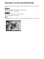


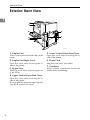
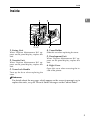
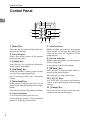


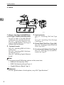
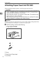
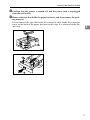
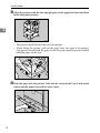

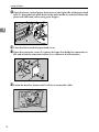
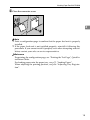
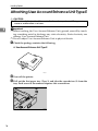

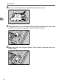


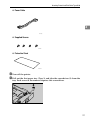
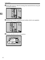

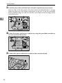
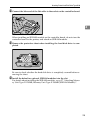
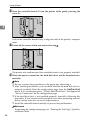
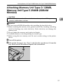


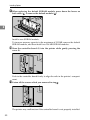
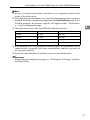
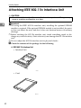
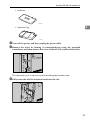

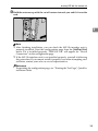
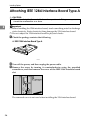


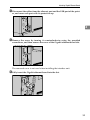

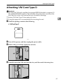


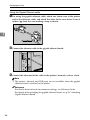

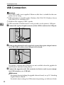
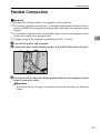

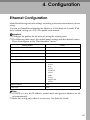
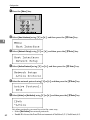
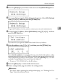
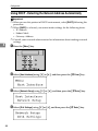
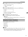
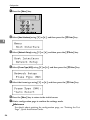
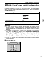
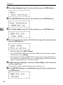


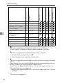
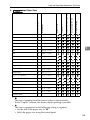
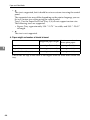

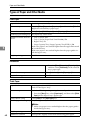
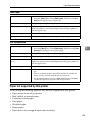
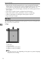
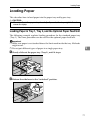
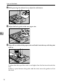
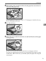

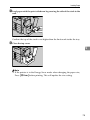
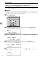
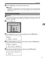
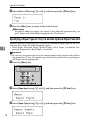
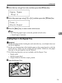
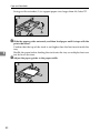


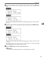

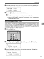


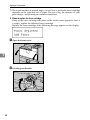

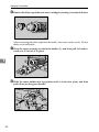
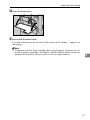
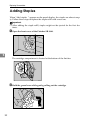
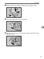
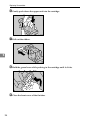

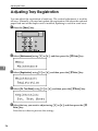
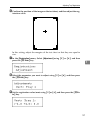
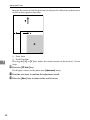
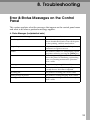
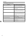
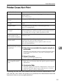


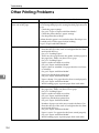
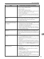

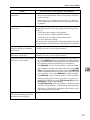
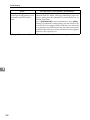
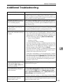
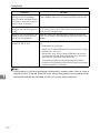
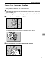

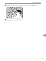
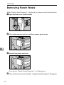
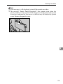

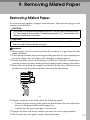


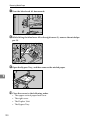
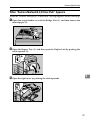
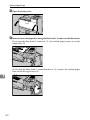

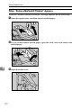
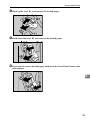
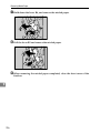
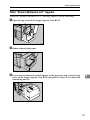
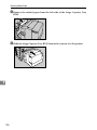
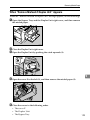


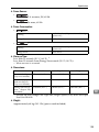
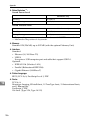
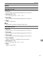
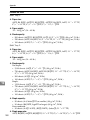


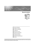
![quindi fare clic su [OK]. - Firmware Center](http://vs1.manualzilla.com/store/data/006146493_1-a65fa0368bddccb764b2c8ac1eae6499-150x150.png)