1
Operating Instructions
Hardware Guide
1
Guide to the Printer
2
Installing Options
3
Connecting the Printer
4
Configuration
5
Paper and Other Media
6
Replacing Consumables and Maintenance Kit
7
Cleaning the Printer
8
Adjusting the Printer
9
Troubleshooting
10 Removing Misfed Paper
11 Appendix
Read this manual carefully before you use this machine and keep it handy for future reference. For safe and correct use, be sure to read “Safety
Information” before using the machine.
TABLE OF CONTENTS
Trademarks.............................................................................................................1
Positions of RWARNING and RCAUTION labels ..............................................2
Manuals for This Printer........................................................................................4
How to Read This Manual .....................................................................................5
Symbols .....................................................................................................................5
Description for the Specified Model.....................................................................6
Installing the Operating Instructions ...................................................................7
1. Guide to the Printer
Exterior: Front View...............................................................................................9
Exterior: Rear View ..............................................................................................11
Inside.....................................................................................................................12
Control Panel........................................................................................................13
Display Panel........................................................................................................14
Reading the Display and Using Keys.......................................................................14
2. Installing Options
Available Options.................................................................................................15
Option List ................................................................................................................15
Option Installation Flow Chart ..................................................................................16
Installing Options...................................................................................................... 17
Caution when re-installing the controller board........................................................19
Attaching Paper Feed Unit Type 4000................................................................20
Attaching Memory Unit Type D 128MB,
Memory Unit Type E 256MB (SDRAM Module)................................................23
Attaching User Account Enhance Unit Type E ................................................. 28
Attaching Hard Disk Drive Type 4000 ................................................................33
Attaching IEEE 802.11b Interface Unit ...............................................................39
Attaching IEEE 1284 Interface Board Type A....................................................42
Attaching the USB Host Interface Board Type A ..............................................44
Attaching Gigabit Ethernet Board Type A .........................................................46
Attaching Data Overwrite Security Unit Type E ................................................49
Attaching the Camera Direct Print Card ............................................................ 51
Attaching VM Card Type D..................................................................................53
Attaching Data Storage Card Type A .................................................................55
3. Connecting the Printer
Network Connection ............................................................................................57
Reading the LED Lamps ..........................................................................................59
USB Connection...................................................................................................60
Connecting a digital camera ...............................................................................61
Parallel Connection .............................................................................................63
i
4. Configuration
Ethernet Configuration........................................................................................65
Using DHCP - Detecting the Network Address Automatically..................................68
Making Network Settings for Using Netware............................................................ 70
IEEE 802.11b (Wireless LAN) Configuration .....................................................72
5. Paper and Other Media
Paper and Other Media Supported by This Printer...........................................77
Paper Recommendations....................................................................................81
Loading Paper..........................................................................................................81
Storing Paper ...........................................................................................................81
Types of Paper and Other Media ............................................................................. 82
Paper not supported by this printer .......................................................................... 87
Print Area .................................................................................................................88
Loading Paper ...................................................................................................... 89
Loading Paper in Tray 1 and the optional paper feed unit .......................................89
Loading Paper in the Bypass Tray ...........................................................................99
Switching between Paper Trays.............................................................................106
6. Replacing Consumables and Maintenance Kit
Replacing the Toner Cartridge .........................................................................107
Replacing the Photo Conductor Unit ...............................................................111
Replacing the Intermediate Transfer Unit........................................................117
Replacing the Waste Toner Bottle.................................................................... 122
Replacing the Maintenance Kit.........................................................................125
Before Replacing.................................................................................................... 125
Replacing the Friction Pad .....................................................................................126
Replacing the Paper Feed Roller ........................................................................... 128
Replacing the Transfer Roller ................................................................................130
Replacing the Fusing Unit ...................................................................................... 132
Replacing the Dustproof Filter................................................................................134
7. Cleaning the Printer
Cautions to Take When Cleaning .....................................................................137
Cleaning the Friction Pad..................................................................................138
Cleaning the Paper Feed Roller........................................................................140
Cleaning the Registration Roller ......................................................................143
8. Adjusting the Printer
Adjusting the Color Registration......................................................................145
Correcting the Color Gradation ........................................................................147
Set the Gradation Correction Value .......................................................................148
Viewing the Color Calibration Sample Sheet and Gradation Correction Sheet ..... 151
Resetting the gradation correction value to the initial value...................................153
Adjusting Tray Registration.............................................................................. 154
ii
9. Troubleshooting
Error & Status Messages on the Control Panel ..............................................157
Panel Tone..........................................................................................................159
Printer Does Not Print .......................................................................................160
Checking the port connection.................................................................................161
Other Printing Problems ...................................................................................163
Additional Troubleshooting .............................................................................. 168
10.Removing Misfed Paper
Removing Misfed Paper ....................................................................................171
When the Paper Misfeed Message Appears (Cover A)...................................172
When the Paper Misfeed Message Appears (Cover Z) ...................................175
11.Appendix
Moving and Transporting the Printer...............................................................177
Moving the Printer ..................................................................................................178
Consumables .....................................................................................................179
Toner Cartridge ......................................................................................................179
Waste Toner Bottle ................................................................................................180
Photo Conductor Unit.............................................................................................180
Intermediate Transfer Unit (Transfer Unit) ............................................................. 181
Maintenance Kit .....................................................................................................181
Specifications.....................................................................................................182
Mainframe ..............................................................................................................182
Options...................................................................................................................185
INDEX....................................................................................................... 189
iii
iv
Trademarks
Microsoft, Windows and Windows NT are registered trademarks of Microsoft
Corporation in the United States and/or other countries.
Adobe®, PostScript®, Acrobat®, PageMaker® and Adobe Type Manager are registered trademarks of Adobe Systems Incorporated.
PCL® is a registered trademark of Hewlett-Packard Company.
Apple, AppleTalk, EtherTalk, Macintosh, Mac OS, and True Type are trademarks of Apple Computer, Inc., registered in the U.S. and other countries.
IPS-PRINT Printer Language Emulation Copyright© 1999-2000 Oak Technology, Inc., All rights reserved.
NetWare is a registered trademark of Novell, Inc.
PictBridge is a trademark.
Other product names used herein are for identification purposes only and might
be trademarks of their respective companies. We disclaim any and all rights to
those marks.
The proper names of the Windows operating systems are as follows:
• Microsoft® Windows® 95 operating system
• Microsoft® Windows® 98 operating system
• Microsoft® Windows® Millennium Edition (Windows Me)
• The product names of Windows® 2000 are as follows:
Microsoft® Windows® 2000 Advanced Server
Microsoft® Windows® 2000 Server
Microsoft® Windows® 2000 Professional
• The product names of Windows® XP are as follows:
Microsoft® Windows® XP Professional
Microsoft® Windows® XP Home Edition
• The product names of Windows Server® 2003 are as follows:
Microsoft® Windows Server® 2003 Standard Edition
Microsoft® Windows Server® 2003 Enterprise Edition
Microsoft® Windows Server® 2003 Web Edition
• The product names of Windows NT® 4.0 are as follows:
Microsoft® Windows NT® Server 4.0
Microsoft® Windows NT® Workstation 4.0
1
Positions of RWARNING and RCAUTION labels
This machine has labels for RWARNING and RCAUTION at the positions
shown below. For safety, please follow the instructions and handle the machine
as indicated.
BEU001S
High temperature parts. Turn off the main power and be careful when replacing
fusing unit/removing misfed paper.
The inside of this printer becomes very hot. Do not touch parts labelled “v” (indicating a hot surface). Touching these parts will result in burns.
2
Do not incinerate used toner or toner containers. Toner dust might ignite when
exposed to an open flame.
Do not incinerate spilled toner or used toner. Toner dust is flammable and might
ignite when exposed to an open flame.
Disposal should take place at an authorized dealer or an appropriate collection
site.
If you dispose of the used toner containers yourself, dispose of them according
to local regulations.
3
Manuals for This Printer
For particular functions, see the relevant parts of the manual.
❖ Safety Information
Provides information on safe usage of this machine.
To avoid injury and prevent damage to the machine, be sure to read this.
❖ Quick Installation Guide
Contains procedures for removing the printer from its box, connecting it to a
computer, and installing its driver.
❖ Hardware Guide
Contains information about paper and procedures such as installing options,
replacing consumables, responding to error messages, and resolving jams.
❖ Software Guide
Contain procedures for using this machine in a network environment, utilizing the software, and using security functions.
❖ Security Guide
This manual is for administrators of the machine. It explains security functions that the administrators can use to protect data from being tampered, or
prevent the machine from unauthorized use. Also refer to this manual for the
procedures for registering administrators, as well as setting user and administrator authentication.
4
How to Read This Manual
Symbols
This manual uses the following symbols:
Indicates important safety notes.
Ignoring these notes could result in serious injury or death. Be sure to read these
notes. They can be found in the Safety Information.
Indicates important safety notes.
Ignoring these notes could result in moderate or minor injury, or damage to the
machine or to property. Be sure to read these notes. They can be found in the
Safety Information.
Indicates points to pay attention to when using the machine, and explanations
of likely causes of paper misfeeds, damage to originals, or loss of data. Be sure
to read these explanations.
Indicates supplementary explanations of the machine’s functions, and instructions on resolving user errors.
This symbol is located at the end of sections. It indicates where you can find further relevant information.
[]
Indicates the names of keys that appear on the machine’s display panel.
{}
Indicates the names of keys on the machine’s control panel.
5
Description for the Specified Model
In this manual, the following items explain about the printer for the specified
models:
This explains about the 220-240 V model printer. You can identify the model by
checking the label on the rear of the printer.
Read if you purchase this model.
This explains about the 120 V model printer. You can identify the model by
checking the label on the rear of the printer.
Read if you purchase this model.
Note
❒ You can identify the printer's model by checking the label on the rear of the
printer as shown.
AQC065S
6
Installing the Operating Instructions
The CD-ROM “Manuals” provided with the printer contains an HTML Operating Instructions Manual in HTML version. Follow this instructions to install it.
Important
❒ System Requirements :
• Windows 95/98/Me, Windows 2000/XP, Windows Server 2003 or Windows NT4.0.
• 800 × 600 or higher monitor resolution.
❒ Web Browsers :
• Microsoft Internet Explorer 5.5 SP2 or higher
• Firefox 1.0 or higher
A Quit all applications currently running.
B Insert the CD-ROM “Manuals” into the CD-ROM drive.
The installer starts.
Auto Run may not work under certain operating system setting. If this is the
case, launch “Setup.exe” on the CD-ROM root directory.
C Select an interface language, and then click [OK].
D Click [Install manuals].
E Follow the instructions on the screen to complete the installation.
F Click [Finish] when the installation is completed.
G Click [Exit].
Note
❒ Auto Run may not work under certain operating system setting. If this is
the case, copy all data on the CD-ROM root directory to your hard disk
drive, and then launch “Setup.exe” to start the installation.
❒ To uninstall the Operating Instructions Manual, select [Programs] in the
[Start] menu, select your printer driver, and then click [uninstall]. You can
uninstall each Manual Guide separately.
❒ If you are using an incompatible Web browser and the simpler version of
the Operating Instructions Manual does not display correctly, open the
folder “MANUALLANG (language) \ (manual name) unv” on the CDROM “Manuals”, and then double-click on “index.htm”.
7
8
1. Guide to the Printer
Exterior: Front View
AQC021S
1. Control Panel
5. Tray 1
Contains keys for printer control and a
display that shows the printer status.
Up to 550 sheets of plain paper can be
loaded.
2. Front Cover
6. Standard Tray
Open the front cover to replace the fusing
unit or transfer roller, or to remove
jammed paper.
The front cover can be opened in two
ways:
To replace the fusing unit or roller, pull
the levers marked “A” on either side of
the printer. To remove jammed paper,
press the button marked “Z” on the right
side of the printer.
Output is stacked here with the print side
down.
3. Bypass Tray
Releases heat from internal components
to prevent overheating. Malfunctions occur if the vent is blocked or obstructed.
The dustproof filter needs to be replaced
regularly for proper maintenance.
Up to 100 sheets of plain paper can be
loaded.
4. Power Switch
Use this switch to turn the power on and
off.
7. Top Cover
Open this cover when replacing the toner
cartridge.
8. Front Cover (A) Open Levers
9. Intake Port
10. Ventilator
11. Front Cover (Z) Open Button
9
Guide to the Printer
Note
❒ When setting paper larger than A5 K, pull out the paper extender as shown.
For details about the sizes and types of paper that can be used, see p.77 “Paper
and Other Media Supported by This Printer”.
1
AQC022S
10
Exterior: Rear View
Exterior: Rear View
1
AQC200S
1. Controller Board
5. Expansion Card Slots
Slide this out to install options such as the
memory unit, user account enhance unit
or printer hard disk. Plug cables such as
the USB cable and Ethernet cable into
their connectors.
Install expansion cards in these slots.
There are three slots.
When you use the expansion card, use
the center slot.
2. Ethernet Port
Use a network interface cable to connect
the printer to the network.
6. Front Cover (A) Open Levers
7. Left Cover
3. USB Port
Open this cover when replacing the photo conductor unit (PCU), intermediate
transfer unit or waste toner cartridge.
Use a USB cable to connect the printer to
the host computer.
8. Power Cable
4. Optional Interface Board Slots
Insert an optional IEEE 802.11b interface
unit, wireless interface board, or 1284 interface board in this slot. Up to two interface board can be inserted at a time.
The power cable is separated. Connect
the power cable to the printer.
The power cable is fixed to the back side.
11
Guide to the Printer
Inside
1
BEU002S
1. Toner Cartridge
4. Inner Cover
Loads from the printer rear, in the order
of yellow (Y), cyan (C), magenta (M), and
black (K).
If the message which prompts you to replace toner appears on the screen, replace
the indicated color of the toner cartridge.
Open this when replacing the photo conductor units or intermediate transfer
unit.
2. I n te r m e d i a t e T r a ns f e r U n i t
(Transfer Unit)
If the message which prompts you to replace it appears on the display, replace
the transfer unit .
3. Photo Conductor Unit
If the message which prompts you to replace it appears on the display, replace
the photo conductor unit.
5. Waste Toner Bottle
Collects toner that is wasted during
printing.
If the message which prompts you to replace it appears on the display, replace
the waste toner bottle.
6. Fusing Unit
If the message which prompts you to replace it appears on the display, replace
the fusing unit.
7. Transfer Roller
If the message which prompts you to replace it appears on the display, replace
the transfer roller.
Reference
For details about the messages which appear on the screen to prompt you to
replace the units, see p.157 “Error & Status Messages on the Control Panel”.
12
Control Panel
Control Panel
1
AQC024S
1. Display
6. Power indicator
Displays current printer status and error
messages.
For details about error messages, see
p.157 “Error & Status Messages on the
Control Panel”.
This indicator remains lit while the power is
on. It is unlit when the power is off or while
the printer is in the Energy Saver mode.
7. Alert indicator
Correspond to the function items at the
bottom line on the display.
Example: In the initial screen, when the
instruction “press [Option]” appears in
this manual, press the left selection key.
Lights up whenever a printer error occurs. A red light indicates an error has occurred that makes printing impossible;
the yellow light indicates a potential error during printing.
If the red light is on, follow the instructions that appear on the display.
3. {Online} key
8. Data In indicator
Indicates whether the printer is online or
offline. Press this to switch between online and offline.
When the lamp is lit, the printer is online, enabling data reception from the host computer.
When the lamp is unlit, the printer is offline, disabling data reception from the
host computer.
Press to return to the ready condition.
Blinks when the printer is receiving data
from a computer. The Data In indicator is
lit if there is data to be printed.
Press to move the cursor in each direction, step by step.
When the {U}, {T}, {V}, or {W} key appears in this manual, press the scroll key
of the same direction.
4. {Job Reset} key
10. {OK} key
When the printer is online, press this key
to cancel an ongoing print job.
Press this key to execute menu items selected on the display.
5. {Menu} key
11. {Escape} key
Press this key to make and check the current printer settings.
For details, See “Making Printer Settings
Using the Control Panel”, Software Guide.
Press this key to return to the previous
condition on the display.
2. Selection keys
9. Scroll keys
13
Guide to the Printer
Display Panel
This section describes configuration using the display panel on the initial screen.
1
AQC060S
1. Operational status or messages
3. [Prt.Jobs]
Displays current machine status, such as
“Ready”, “Offline”, and “Printing...”.
Press to display print jobs sent from a
computer.
For details, see Software Guide.
2. [Option]
Press to display the status of options installed in the printer.
4. [Supplies]
Press to display the menu of supplies fir
the printer.
Reading the Display and Using Keys
This section explains how to read the display and using the selection key for the
initial display.
1
2
4
AQC061S
1. {Escape} key
4. Selection keys
Press to cancel an operation or return to
the previous display.
Correspond to the function items at the
bottom line on the display.
Example: In the initial screen, when the
instruction “press [Option]” appears in
this manual, press the left selection key.
2. {OK} key
Press to set a selected item or entered numeric value.
3. Scroll keys
Press to move the cursor in each direction, step by step.
When the {U}, {T}, {V}, or {W} key appears in this manual, press the scroll key
of the same direction.
14
3
2. Installing Options
Available Options
This section describes how to install options.
By installing options, you can improve the printer performance and have an expanded variety of features to use. For the specifications of each option, see p.182
“Specifications”.
R CAUTION:
• Before installing options, the machine should be turned off and unplugged
for at least an hour. Components inside the machine become very hot, and
can cause a burn if touched.
• Before moving the machine, unplug the power cable from the outlet. If the
cable is unplugged abruptly, it could become damaged. Damaged plugs or
cables can cause an electrical or fire hazard.
• When lifting the machine, use the grips on both sides. The machine could
break or cause an injury if dropped.
Important
❒ The voltage rating of the connector for options is 24 V DC or less.
Option List
The following is a list of options for this printer.
• Paper Feed Unit Type 4000
• Hard Disk Drive Type 4000
• Memory Unit Type D 128MB
• Memory Unit Type E 256MB
• User Account Enhance Unit Type E
• IEEE 802.11b Interface Unit
• IEEE 1284 Interface Board Type A
• USB Host Interface Board Type A
• Gigabit Ethernet Board Type A
• Camera Direct Print Card Type B
• Data Overwrite Security Unit Type E
• VM Card Type D
• Data Storage Card Type A
15
Installing Options
Option Installation Flow Chart
Installing multiple options in the following order is recommended:
A Attach the paper feed unit (Paper Feed Unit Type 4000).
Attach the paper feed units to the bottom of the printer.
You can attach up to two paper feed units. Up to 1750 sheets of paper can be
loaded in total.
2
B Install the SDRAM module (Memory Unit Type D 128MB, Memory Unit
Type E 256MB).
Install the module to the SDRAM module slot on the controller board.
There are two types of memory unit: 128 MB and 256 MB.
C Install User Account Enhance Unit (User Account Enhance Unit Type E).
Install the module to the User Account Enhance Unit slot of the controller
board.
D Install the hard disk drive (Hard Disk Drive Type 4000).
Install the hard disk drive to the controller board.
E Install the IEEE 1284 interface board, IEEE 802.11b interface unit, USB host
interface board, or Gigabit Ethernet board.
Install the IEEE 1284 interface board, IEEE 802.11b interface unit, USB host interface board, or Gigabit Ethernet board on the controller board.
Up to two of the followings can be installed:
• IEEE 1284 Interface Board Type A
• IEEE 802.11b Interface Unit
• USB Host Interface Board Type A
• Gigabit Ethernet Board Type A
F Install the security unit (Data Overwrite Security Unit Type E, Data Storage
Card Type A), the Camera Direct Print card (Camera Direct Print Card Type
B), or the VM card (VM Card Type D).
Insert these units into the expansion card slot on the controller board.
16
Available Options
Installing Options
Install options in the positions shown in the illustration.
❖ Exterior
2
AET061S
1. Paper Feed Unit Type 4000
Loads up to 550 sheets of paper.
Up to two paper feed units, can be installed on the printer. Installed tray units are
identified as “Tray 2” and “Tray 3”.
See p.20 “Attaching Paper Feed Unit Type 4000”.
17
Installing Options
❖ Interior
2
AQC040S
1. Memory Unit Type D 128MB/
Memory Unit Type E 256MB
(SDRAM module)
Install 128 MB or 256 MB SDRAM
module into the controller board slot.
See p.23 “Attaching Memory Unit
Type D 128MB, Memory Unit Type E
256MB (SDRAM Module)”.
2. Optional boards
See p.39 “Attaching IEEE 802.11b Interface Unit”.
See p.42 “Attaching IEEE 1284 Interface Board Type A”.
See p.44 “Attaching the USB Host Interface Board Type A”.
See p.46 “Attaching Gigabit Ethernet
Board Type A”.
3. Optional units
See p.49 “Attaching Data Overwrite
Security Unit Type E”.
See p.51 “Attaching the Camera Direct
Print Card”.
See p.53 “Attaching VM Card Type
D”.
See p.55 “Attaching Data Storage
Card Type A”.
4. Hard Disk Drive Type 4000
See p.33 “Attaching Hard Disk Drive
Type 4000”.
5. User Account Enhance Unit Type E
See p.28 “Attaching User Account Enhance Unit Type E”.
Note
❒ You can have two of the following types of extension board installed at the
same time: IEEE 802.11b Interface Unit, IEEE 1284 Interface Board Type A,
USB Host Interface Board Type A, and Gigabit Ethernet Board Type A.
❒ Some printer models come with the Expansion Hard Disk Drive Unit and
Data Overwrite Security Unit installed as default.
Reference
For the specifications of each option, see p.182 “Specifications”.
18
Available Options
Caution when re-installing the controller board
This section describes handling the controller board when installing options.
If you slide out the controller board to install the SDRAM module, the user account enhance unit, or the printer hard disk, carefully follow the instruction below to re-install the controller board.
• Re-install the controller board into the printer by pushing the bottom center
area of the board, as shown in the illustration.
2
AQC004S
Important
❒ The following may occur if the controller board is not properly installed:
• all control panel indicators are lit.
• no control panel indicators is lit.
• the “SC670” error message appears on the display.
19
Installing Options
Attaching Paper Feed Unit Type 4000
When installing multiple options, install the paper feed unit first.
R CAUTION:
• The printer weights approximately 50 kg (110.3 lb.). When moving the printer, use the inset grips on both sides, and lift slowly. The printer will break or
cause injury if dropped.
2
R CAUTION:
• Lifting the paper feed unit carelessly or dropping it may cause injury.
Important
❒ Up to two paper feed units can be attached to the printer.
❒ When two paper feed units are installed, they are detected as “Tray 2” and
“Tray 3” starting from the upper unit.
❒ Before using the new paper feed unit, you must make settings in the printer
driver.
❒ Check the printer nameplate to confirm the model code.
A Check the package contains the following:
❖ Paper Feed Unit (including a paper tray)
AET108S
B Turn off the power, and then unplug the power cable.
C Remove the orange fastening tapes from the paper feed unit.
20
Attaching Paper Feed Unit Type 4000
D Lift the printer using the inset grips on both sides of the printer.
2
AET034S
Important
❒ The printer should always be lifted by at least two people.
E Align the printer with the two upright pins on the paper feed unit and then
lower the printer slowly.
AET074S
When installing two paper feed units, connect the two units first using the
same procedure below before connecting the units to the printer.
AET075S
21
Installing Options
Note
❒ When moving the printer, remove the paper feed unit.
❒ After finishing installation, you can check whether the paper feed unit is
properly installed: Print the configuration page from the [List/Test Print]
menu. If it is installed properly, “Tray 2” or “Tray 2”, “Tray 3” will appear
for “Connection Equipment” on the configuration page.
❒ If the paper feed unit is not installed properly, reinstall it following this
procedure. If you cannot install it properly even after attempting reinstallation, contact your sales or service representative.
2
Reference
For printing the configuration page, see “Test Printing”, Quick Installation
Guide.
For loading paper onto the paper tray, see p.89 “Loading Paper”.
When adjusting the printing position, see p.154 “Adjusting Tray Registration”.
22
Attaching Memory Unit Type D 128MB, Memory Unit Type E 256MB (SDRAM Module)
Attaching Memory Unit Type D 128MB,
Memory Unit Type E 256MB (SDRAM Module)
R CAUTION:
• Do not touch the inside of the controller board compartment. Doing so may
cause a malfunction or a burn.
2
Important
❒ Before touching the memory unit, ground yourself by touching something
metal to discharge any static electricity. Static electricity can damage the
memory unit.
❒ Do not subject the memory unit to physical shocks.
❒ Available memory varies depending on a model type.
❒ Before using the new memory unit, Be sure to make settings in the printer
driver.
A Turn off the power, and then unplug the power cable.
B Loosen the three screws securing the controller board.
AQC630S
The screws cannot be fully removed.
C Grasp the handles and carefully pull out the controller board.
AQC640S
23
Installing Options
Using both hands, slide the controller board completely out.
2
AQC650S
D Place the controller board on a flat surface, and then loosen the four screws
to remove the cover.
AQC660S
The screws cannot be fully removed.
E Be sure to install the SDRAM module as shown.
AQC670S
Two slots are provided for the SDRAM modules.
The default SDRAM module is installed in the inner slot.
To install an additional memory, attach an additional SDRAM module to the
outer slot, or replace the default SDRAM module.
24
Attaching Memory Unit Type D 128MB, Memory Unit Type E 256MB (SDRAM Module)
F When installing an SDRAM module in a vacant slot, align the notch of the
SDRAM module with the slot, and then insert the module vertically.
2
AET076S
G Press down the SDRAM module, until it clicks into place.
AET077S
H When replacing the default SDRAM module, press down the levers on
both sides ( ) to remove the default module ( ).
AET078S
Install a new SDRAM module.
To increase memory capacity to the maximum of 512 MB, remove the default
SDRAM module, and then install two 256 MB SDRAM modules.
25
Installing Options
I To install other options on the controller board, follow the appropriate installation procedure(s), and then screw down the controller board cover.
J Fasten the four screws to attach the cover.
2
AQC700S
K Align the controller board with the left and right rails, and then push it
carefully in, until it stops.
AQC710S
The printer may malfunction if the controller board is not properly installed.
L Fasten the controller board to the printer using the three screws.
AQC720S
26
Attaching Memory Unit Type D 128MB, Memory Unit Type E 256MB (SDRAM Module)
Note
❒ Be sure to return the provided screwdriver to its original position on the
inside of the front cover.
❒ After finishing the installation, you can check the memory unit is properly
installed: Print the configuration page from the [List/Test Print] menu. If it is
installed properly, the memory capacity will appear under “Total Memory” on the configuration page.
❒ The table below shows the total SDRAM module capacities.
Standard
Extended
2
Total
256 MB
128 MB
384 MB
256 MB
256 MB
512 MB
❒ If the memory unit is not properly installed, repeat this procedure. If you
cannot install it properly even after reinstallation, contact your sales or service representative.
Reference
For printing the configuration page, see “Test Printing”, Quick Installation
Guide.
Install the controller board carefully. For details, see p.19 “Caution when
re-installing the controller board”.
27
Installing Options
Attaching User Account Enhance Unit Type E
R CAUTION:
• Do not touch the inside of the controller board compartment. Doing so may
cause a malfunction or a burn.
Important
❒ Before touching the User Account Enhance Unit, ground yourself by touching something metal to discharge any static electricity. Static electricity can
damage User Account Enhance Unit.
2
❒ Do not subject User Account Enhance Unit to physical shocks.
A Check the package contains the following:
❖ User Account Enhance Unit Type E
AET080S
B Turn off the power, and then unplug the power cable.
C Loosen the three screws securing the controller board.
AQC630S
The screws cannot be fully removed.
28
Attaching User Account Enhance Unit Type E
D Grasp the handles, and then pull the controller board carefully out.
2
AQC640S
Using both hands, slide the controller board completely out.
AQC650S
E Place the controller board on a flat surface. Loosen the five screws to remove the cover
AQC660S
The screws cannot be fully removed.
29
Installing Options
F Be sure to install the User Account Enhance Unit as shown.
2
AQC680S
G Align the notch of User Account Enhance Unit, and then insert it into the
controller board, pressing it down until it clicks into place.
AET081S
H Make sure that User Account Enhance Unit is firmly connected to the controller board.
AET082S
30
Attaching User Account Enhance Unit Type E
I Fasten the four screws to attach the cover.
2
AQC700S
J Align the controller board with the left and right rails, and then push it
carefully in, until it stops.
AQC710S
Push on the area of the controller board that is marked “PUSH”. Push in the
controller board until it can go no further.
The printer may malfunction if the controller board is not properly installed.
K Fasten the controller board to the printer using the three screws.
AQC720S
31
Installing Options
Note
❒ After finishing installation, you can check User Account Enhance Unit is
properly installed: Print the configuration page from the [List/Test Print]
menu. If it is installed properly, “Accounting Module” will appear for “Device Connection” on the configuration page.
❒ If the User Account Enhance Unit is not installed properly, reinstall it following this procedure. If you cannot install it properly even after attempting reinstallation, contact your sales or service representative.
2
Reference
For printing the configuration page, see “Test Printing”, Quick Installation
Guide.
Install the controller board carefully. For details, see p.19 “Caution when
re-installing the controller board”.
32
Attaching Hard Disk Drive Type 4000
Attaching Hard Disk Drive Type 4000
R CAUTION:
• Do not touch the inside of the controller board compartment. Doing so may
cause a machine malfunction or a burn.
Important
❒ Before touching the hard disk drive, touch something metal to discharge any
static electricity. Static electricity can damage the hard disk drive.
2
❒ Do not subject the hard disk drive to physical shocks.
❒ Before using the new hard disk drive, be sure to make the settings in the printer driver.
A Check the package contains the following:
❖ Hard Disk Drive
AET083S
❖ Flat Cable
AQC500S
33
Installing Options
❖ Power Cable
2
AET085S
❖ Four Screws
AET086S
B Turn off the power, and then unplug the power cable.
C Loosen the three screws securing the controller board.
AQC630S
The screws cannot be fully removed.
34
Attaching Hard Disk Drive Type 4000
D Grasp the handles, and then pull the controller board carefully out.
2
AQC640S
Using both hands, slide the controller board completely out.
AQC650S
E Place the controller board on a flat surface, and then loosen the four screws
to remove the cover.
AQC660S
The screws cannot be fully removed.
35
Installing Options
F Be sure to install the hard disk drive unit as shown.
2
AET069S
G Use the screws supplied with the hard disk drive to secure the unit to the
controller board.
AET087S
H Connect the power cable to the hard disk drive and controller board.
AET088S
36
Attaching Hard Disk Drive Type 4000
I Connect the flat cable to the hard disk drive and the controller board. Connect the blue end of the flat cable to the controller board.
2
AQC0006S
J When installing other options on the controller board, do not close the controller board, but go to the steps for installing the option.
K Fasten the four screws to attach the cover.
AQC700S
L Align the controller board with the left and right rails, and then push it
carefully in, until it stops.
AQC710S
Push only on the area of the controller board that is marked “PUSH”. Push in
the controller board until it can go no further.
The printer may malfunction if the controller board is not properly installed.
37
Installing Options
M Fasten the controller board to the printer using the three screws.
2
AQC720S
When the power is turned on, the hard disk drive will be formatted automatically.
Note
❒ After finishing installation, you can check whether the hard disk drive is
properly installed: Print the configuration page from the [List/Test Print]
menu. If it is installed properly, “Hard Disk Drive” will appear for “Device
Connection” on the configuration page.
❒ If the hard disk drive is not installed properly, reinstall it following this
procedure. If you cannot install it properly even after attempting reinstallation, contact your sales or service representative.
Reference
For printing the configuration page, see “Test Printing”, Quick Installation
Guide.
Install the controller board carefully. For details, see p.19 “Caution when
re-installing the controller board”.
38
Attaching IEEE 802.11b Interface Unit
Attaching IEEE 802.11b Interface Unit
R CAUTION:
• Do not touch the inside of the controller board compartment. Doing so may
cause a machine malfunction or a burn.
Important
❒ Before touching the 802.11b interface unit, touch something metal to discharge
any static electricity. Static electricity can damage the 802.11b interface unit.
2
❒ Do not subject the 802.11b interface unit to physical shocks.
A Check the contents of the package for the following:
❖ IEEE 802.11b Interface Unit
• Interface Unit
AAL151S
• Card
ZHBP420E
• Antenna
ZHBP430E
39
Installing Options
• Antenna Cap
AAL888S
B Turn off the power, and then unplug the power cable.
C Loosen the two screws and remove the cover of the 802.11b interface unit
2
installation unit.
AQC091S
The removed cover is not used when installing the interface unit.
D Fully insert the 802.11b interface unit.
AET094S
E Tighten the two screws to secure the interface unit.
AQC095S
40
Attaching IEEE 802.11b Interface Unit
F Attach the antenna to the card with the label facing down and the uneven
side of the antenna facing up.
2
AET096S
G With the antenna and the indented end toward you, slowly insert the interface card until it stops.
AQC097S
H Hold the antenna cap with the cut off corners towards you and fit it over the card.
AQC098S
Note
❒ After finishing installation, you can check the 802.11b interface unit is
properly installed: Print the configuration page from the [List/Test Print]
menu. If it is installed properly, “IEEE 802.11b” will appear for “Device
Connection” on the configuration page.
❒ If the 802.11b interface unit is not installed properly, reinstall it following
this procedure. If you cannot install it properly even after attempting reinstallation, contact your sales or service representative.
Reference
For printing the configuration page, see “Test Printing”, Quick Installation Guide.
41
Installing Options
Attaching IEEE 1284 Interface Board Type A
R CAUTION:
• Do not touch inside the controller board compartment. Doing so may cause
a machine malfunction or a burn.
Important
❒ Before handling the 1284 interface board, touch something metal to discharge
static electricity. Static electricity thing damage the 1284 interface board.
2
❒ Do not subject the 1284 interface board to physical shocks.
A Check the package contains the following:
❖ IEEE 1284 Interface Board Type A
ABT041S1
B Turn off the power, and then unplug the power cable.
C Loosen the two screws and remove the cover of the 1284 interface board installation unit.
AQC091S
The removed cover is not used when installing the 1284 interface board.
42
Attaching IEEE 1284 Interface Board Type A
D Fully insert the 1284 interface board.
2
AET102S
Confirm that the 1284 interface board is firmly connected to the controller
board.
E Tighten the two screws to secure the 1284 interface board.
AQC103S
Note
❒ Use the supplied adaptor to make the connection with the computer.
❒ After finishing installation, you can check the 1284 interface board is properly installed: Print the configuration page from the [List/Test Print] menu.
If it is installed properly, “Parallel Interface” will appear for “Device Connection” on the configuration page.
❒ If the 1284 interface board is not installed properly, reinstall it following
this procedure. If you cannot install it properly even after attempting reinstallation, contact your sales or service representative.
Reference
For printing the configuration page, see “Test Printing”, Quick Installation
Guide.
43
Installing Options
Attaching the USB Host Interface Board Type A
Important
❒ When connecting a digital camera to the printer via USB, the USB port of the
USB host interface board is required.
❒ Before handling the USB host interface board, ground yourself by touching
something metal to discharge any static electricity. Static electricity can damage the USB host interface board.
❒ Do not subject the USB host interface board to physical shocks.
2
A Check the contents of the box.
❖ USB Host Interface Board
AQC041S
B Turn off the power, and then unplug the power cable.
C Loosen the two screws and remove the cover of the USB host interface
board installation unit.
AQC910S
The removed cover is not used when installing the interface unit.
44
Attaching the USB Host Interface Board Type A
D Fully insert the USB host interface board.
2
AQC042S
E Tighten the two screws to secure the USB host interface board.
AQC044S
Check the USB host interface board is inserted firmly to the controller board.
Note
❒ After finishing installation, check the USB host interface board is installed
properly: print the configuration page from the [List/Test Print] menu. If it
is installed properly, you will see “USB Host” for “Device Connection” on
the configuration page.
❒ If the USB host interface board is not installed properly, reinstall it following this procedure. If you cannot install it properly even after attempting
reinstallation, contact your sales or service representative.
❒ You can connect the USB cable from a digital camera to the USB host interface board. For details, see p.61 “Connecting a digital camera”, or Software
Guide.
Reference
For details about printing the configuration page, see “Test Printing”,
Quick Installation Guide.
45
Installing Options
Attaching Gigabit Ethernet Board Type A
Important
❒ The printer's ethernet and USB ports are not available when the gigabit ethernet board is attached to the printer. Instead, you can use the ethernet port
and USB port mounted on the board.
2
❒ Before handling the gigabit ethernet board, ground yourself by touching
something metal to discharge any static electricity. Static electricity can damage the gigabit ethernet board.
❒ Do not subject the gigabit ethernet board to physical shocks.
A Check the contents of the box.
❖ Gigabit Ethernet Board
AGY096S
❖ Protective caps (one each for the ethernet port and the USB port)
AGY097S
❖ Ferrite core (This printer does not require the ferrite core.)
AQC092S
Note
❒ Design of the ferrite core varies according to printer model.
46
Attaching Gigabit Ethernet Board Type A
B Turn off the power, and then unplug the power cable.
C Disconnect the cables from the ethernet port and the USB port of the printer,
and cover each port with its protective cap.
2
AQC046S
D Loosen the two screws and remove the cover of the Gigabit ethernet board
installation unit.
AQC091S
The removed cover is not used when installing the interface unit.
E Fully insert the Gigabit ethernet board.
AQC043S
47
Installing Options
F Tighten the two screws to secure the Gigabit ethernet board.
2
AQC045S
Check the Gigabit ethernet board is connected firmly to the controller board.
Note
❒ After finishing installation, check the Gigabit ethernet board is installed
properly: print the configuration page from the [List/Test Print] menu. If it
is installed properly, you will see “Gigabit Ethernet Board” for “Device
Connection” on the configuration page.
❒ If the Gigabit ethernet board is not installed properly, reinstall it following
this procedure. If you cannot install it properly even after attempting reinstallation, contact your sales or service representative.
❒ You need to make settings with the control panel before using the gigabit
ethernet board. For details, see p.65 “Ethernet Configuration”.
Reference
For details about printing the configuration page, see “Test Printing”,
Quick Installation Guide.
48
Attaching Data Overwrite Security Unit Type E
Attaching Data Overwrite Security Unit Type E
Important
❒ Protect the Data Overwrite Security unit from physical shocks.
❒ Use the right slot for the Data Overwrite Security unit.
A Check the package contains the following:
2
❖ Data Overwrite Security unit
AET104S
B Turn off the power, and then unplug the power cable.
C Remove the cover of the controller board's central expansion card slot.
AQC105S
D Carefully insert the Data Overwrite Security unit, until the card clicks into
place.
AQC106S
49
Installing Options
E Reattach the cover over the Data Overwrite Security unit. Fasten the screw
to secure the cover.
2
AQC107S
Note
❒ Do not touch the Data Overwrite Security unit while the printer is in use.
It may come loose, even if pushed only slightly.
50
Attaching the Camera Direct Print Card
Attaching the Camera Direct Print Card
Important
❒ Protect the Camera Direct Print card from physical shocks.
❒ Use the right slot for the Camera Direct Print card.
A Check the package contains the following:
2
❖ Camera Direct Print Card
AET104S
B Turn off the power, and then unplug the power cable.
C Remove the cover of the controller board's center expansion card slot.
AQC105S
D Carefully insert the Camera Direct Print card, until the card clicks into
place.
AQC106S
51
Installing Options
E Reattach the cover over the Camera Direct Print card. Fasten the screw to secure the cover.
2
AQC107S
Note
❒ Do not touch the Camera Direct Print card while the printer is in use. It
may come loose, even if pushed only slightly.
52
Attaching VM Card Type D
Attaching VM Card Type D
Important
❒ Protect VM Card Type D from physical shocks.
❒ Use the right slot for the VM card.
A Check the package contains the following:
2
❖ VM Card Type D
AET104S
B Turn off the power, and then unplug the power cable.
C Remove the cover of the controller board's center expansion card slot.
AQC105S
D Carefully insert the VM card, until the card clicks into place.
AQC106S
53
Installing Options
E Reattach the cover over the VM card. Fasten the screw to secure the cover.
2
AQC107S
Note
❒ Do not touch the VM card while the printer is in use. It may come loose,
even if pushed only slightly.
54
Attaching Data Storage Card Type A
Attaching Data Storage Card Type A
Important
❒ Protect Data Storage Card Type A from physical shocks.
❒ Use the right slot for the Data Storage card.
A Check the package contains the following:
2
❖ Data Storage Card Type A
AET104S
B Turn off the power, and then unplug the power cable.
C Remove the cover of the controller board's central expansion card slot.
AQC105S
D Carefully insert the Data Storage card, until the card clicks into place.
AQC106S
55
Installing Options
E Reattach the cover over the Data Storage card. Fasten the screw to secure the
cover.
2
AQC107S
Note
❒ Do not touch the Data Storage card while the printer is in use. It may come
loose, even if pushed only slightly.
56
3. Connecting the Printer
Network Connection
Follow the procedure below to connect the printer to the computer through the
network. Prepare the hub and other network devices before connecting the
10BASE-T or 100BASE-TX cable to the printer's Ethernet port.
Alternatively, the optional gigabit ethernet board, which supports 1000BASE-T,
is available.
Important
❒ Use shielded Ethernet cable. Unshielded cables create electromagnetic interference that could cause malfunctions.
❒ The Ethernet cable is not supplied with this printer. Select your cable according to the network environment.
A Attach one ferrite core at the printer end of the Ethernet cable, and then attach the other ferrite core about 10 cm (4 inches) ( ) from this core.
AET121S
B Connect the Ethernet cable to the Ethernet port.
AET122S
57
Connecting the Printer
C If the gigabit ethernet board is attached, connect the ethernet cable to the
board.
3
AQC056S
The printer's ethernet and USB ports are not available when the gigabit ethernet board is attached to the printer.
D Connect the other end of the cable to the printer's network, such as a hub.
Note
❒ The printer's ethernet and USB ports are not available when the gigabit
ethernet board is attached to the printer.
Reference
For details about network environment settings, see Software Guide.
For details about attaching the gigabit ethernet board, see p.46 “Attaching
Gigabit Ethernet Board Type A”.
58
Network Connection
Reading the LED Lamps
❖ For standard ethernet port
3
AQC070S
1. Yellow: comes on when 100BASE-TX is being used. It comes off when
10BASE-T is being used.
2. Green: comes on when the printer is properly connected to the network.
❖ For gigabit ethernet board
AQC070S
1. Green: comes on when 10BASE-T is being used.
2. Yellow: comes on 100BASE-TX is being used.
Green and yellow lamps are lit when 1000BASE-T is being used.
59
Connecting the Printer
USB Connection
Important
❒ USB2.0 interface cable is not supplied. Obtain it separately, according to the
computer you are using.
❒ USB connection is possible under Windows 98 SE/Me/2000/XP, Windows
Server 2003, Mac OS 9.x, and Mac OS X.
❒ Windows 98SE/Me supports USB1.1 speeds.
❒ USB connection with Macintosh is only possible via the printer's USB port.
3
A Connect the square-shaped connector of the USB2.0 cable to the USB port.
AET124S
B If the gigabit ethernet board is attached, connect the square-shaped connector of the USB2.0 cable to the USB port of the board.
AQC055S
The printer's ethernet and USB ports are not available when the gigabit ethernet board is attached to the printer.
C Connect the opposite end's flat connector to devices such as your computer's USB interface, or a USB hub.
Reference
For details about attaching the gigabit ethernet board, see p.46 “Attaching
Gigabit Ethernet Board Type A”.
For details about settings for USB connection printing, see Software Guide.
60
Connecting a digital camera
Connecting a digital camera
This printer supports direct printing, which allows you to print images taken
with digital cameras without using a computer. The following describes how to
connect the printer to a digital camera.
3
AQC047S
Important
❒ This function requires the following optional units:
• USB Host Interface Board Type A (Optional Interface Unit)
• Camera Direct Print Card Type B (Expansion Card)
❒ The USB host interface board is supplied with a USB cable and a hook onto
which you can roll up and hang the cable.
❒ Make sure your digital camera supports PictBridge.
A Attach the hook on the back of the printer near the USB connection slot.
Attach the hook where it will not interfere with printer operation and access.
AQC050S
B Check the printer and the digital camera are both switched on.
61
Connecting the Printer
C Use the USB cable supplied with the USB host interface board to connect
the printer and the digital camera. Connect the flat connector of the USB cable to the USB host interface board.
3
AQC063S
D Connect the square-shaped connector on the opposite end of the USB cable
to the digital camera.
E Secure the USB cable using the hook.
AQC049S
Reference
For details about attaching the USB host interface board, see p.44 “Attaching the USB Host Interface Board Type A”.
For details about attaching the Camera Direct Print card, see p.51 “Attaching the Camera Direct Print Card”.
For details about direct printing, see “Direct Printing from digital camera
(PictBridge)”, Software Guide.
62
Parallel Connection
Parallel Connection
Important
❒ The parallel interface cable is not supplied with the printer.
❒ The printer's parallel connection is a standard bidirectional interface that requires an IEEE 1284-compliant 36-pin parallel cable and host computer parallel port.
❒ Use shielded interface cable. Unshielded cables create electromagnetic interference that could cause malfunctions.
3
A Turn off the printer and computer.
B Connect the cable to the interface socket of the IEEE 1284 interface board.
Important
❒ Voltage rating of the computer's parallel port: DC 5 V (max.)
AKQ010S
C Securely attach the other end of the parallel cable to your computer's parallel port. Secure the cable.
Reference
For details about settings for parallel connection printing, see Software
Guide.
63
Connecting the Printer
3
64
4. Configuration
Ethernet Configuration
Make the following network settings according to the network interface you are
using.
You can use SmartDeviceMonitor for Admin or a Web browser to make IP address-related settings in a TCP/IP-capable environment.
Important
❒ Configure the printer for the network using the control panel.
❒ The following table shows the control panel settings and their default values.
These items appear in the “Host Interface” menu.
Setting Name
Value
Auto- Obtain (DHCP)
On
IPv4 Address
011.022.033.044
Subnet Mask
000.000.000.000
Gateway Address
000.000.000.000
Frame Type (NW)
Auto
Effective Protocol
• IPv4:
Effective
• IPv6:
Effective
• NetWare:
Effective
• SMB:
Effective
• AppleTalk:
Effective
Ethernet Speed
Auto
LAN Type
Auto
Note
❒ If [Auto-Obtain (DHCP)] is in use, the IP address, subnet mask, and gateway address are all set automatically.
❒ Make this setting only when it is necessary. See Software Guide.
65
Configuration
A Press the {Menu} key.
K
C
M
Y
AQC001S
B Select [Host Interface] using {T} or {U}, and then press the {OK} key.
4
C Select [Network] using {T} or {U}, and then press the {OK} key.
D Select [Effective Protocol] using {T} or {U}, and then press the {OK} key.
E Select the network protocol using {T} or {U}, and then press the {OK} key.
66
Ethernet Configuration
F Select [Effective] or [Invalid] using {T} or {U}, and then press the {OK} key.
Set other protocols you need to set in the same way.
• Select [Invalid] for unused protocols.
• Enable IPv4 to use the Pure IPv4 environment of NetWare 5/5.1, NetWare
6/6.5.
G Press the {Escape} key until the screen returns to the [Network] menu.
H If you use IPv4, assign the IPv4 address to the printer. Select [Machine IPv4
4
Address] using {T} or {U}, and then press the {OK} key.
To get the IP address for the printer, contact your network administrator.
I To specify the IP Address, press [IP Add.].
If you use IPv4, assign also Subnet Mask and Gateway Address. To assign
these, press [Subnet M] or [Gateway] instead.
J Enter the address using {T} or {U}, and then press the {OK} key.
Press the {T} or {U} key to enter the left most entry field of the address. After
entering the left field, press the {V} key, and then you can enter the next field.
After completing to enter in the all fields, press the {OK} key. Use this method
to assign Subnet Mask and Gateway Address.
• Do not set “011.022.033.044” as the IP address.
67
Configuration
K Select [Specify] using {T} or {U}, and then press the {OK} key.
If you do not select [Specify] in this step, the address you set will not be saved.
L Press the {Menu} key to return to the initial screen.
M Print a configuration page to confirm the settings made.
Reference
For details about printing the configuration page, see “Test Printing”,
Quick Installation Guide.
4
Using DHCP - Detecting the Network Address Automatically
Important
❒ When you use this printer in DHCP environment, select [Auto-Obtain (DHCP)]
following this procedure.
❒ When [Auto-Obtain (DHCP)] is selected, you cannot make settings for the following items:
• IP Address
• Subnet Mask
• Gateway Address
❒ Consult your network administrator for information about making network
settings.
A Press the {Menu} key.
K
C
M
Y
AQC001S
68
Ethernet Configuration
B Select [Host Interface] using {T} or {U}, and then press the {OK} key.
C Select [Network] using {T} or {U}, and then press the {OK} key.
4
D Select [Machine IPv4 Address] using {T} or {U}, and then press the {OK} key.
E Select [Auto-Obtain (DHCP)] using {T} or {U}, and then press the {OK} key.
The address detected by the printer will appear.
To check the detected addresses, press the followings:
• [IP Add.]
IP address
• [Subnet M]
Subnet Mask
• [Gateway]
Default Gateway
F Press the {Menu} key to return to the initial screen.
G Print a configuration page to confirm the settings made.
Reference
For details about printing the configuration page, see “Test Printing”,
Quick Installation Guide.
69
Configuration
Making Network Settings for Using Netware
If you use NetWare, select the frame type for NetWare.
Select one of the items below if necessary.
• Auto Select
• Ethernet II
• Ethernet 802.2
• Ethernet 802.3
• Ethernet SNAP
Important
❒ Usually, use the default setting ([Auto Select]). When you first select [Auto Select], the frame type detected by the printer is adopted. If your network can
use more than two frame types, the printer may fail to select the correct frame
type if [Auto Select] is selected. In this case, select the appropriate frame type.
4
A Press the {Menu} key.
K
C
M
Y
AQC001S
B Select [Host Interface] using {T} or {U}, and then press the {OK} key.
C Select [Network] using {T} or {U}, and then press the {OK} key.
70
Ethernet Configuration
D Select [NW Frame Type] using {T} or {U}, and then press the {OK} key.
E Select the frame type using {T} or {U}, and then press the {OK} key.
4
F Press the {Menu} key to return to the initial screen.
G Print a configuration page to confirm the settings made.
Reference
For details about printing the configuration page, see “Test Printing”,
Quick Installation Guide.
71
Configuration
IEEE 802.11b (Wireless LAN) Configuration
Configure the printer to use IEEE 802.11b (Wireless LAN). The following table
shows the control panel settings and their default values. These items appear in
the [Host Interface] menu.
Setting Name
Default Value
Communication Mode
802.11 Ad hoc
Channel
• Inch version
(1-11) 11
• Metric version
(1-13) 13
4
Communication Speed
Auto
SSID
blank
WEP
Off
Note
❒ To use IEEE 802.11b (Wireless LAN), select [IEEE 802.11b] for [LAN Type] in [Network] in the [Host Interface] menu, and then set the IP Address, Subnet Mask,
Gateway Address, DHCP, Network Frame Type, and Effective Protocol under [Network]. For details about setting items under “Configuring the Printer
for the Network”, see Software Guide.
❒ The 802.11b interface unit cannot be used simultaneously with a standard
ethernet interface.
A Press the {Menu} key.
K
C
M
Y
AQC001S
B Select [Host Interface] using {T} or {U}, and then press the {OK} key.
72
IEEE 802.11b (Wireless LAN) Configuration
C Select [IEEE 802.11b] using {T} or {U}, and then press the {OK} key.
D Select [Communication Mode] using {T} or {U}, and then press the {OK} key.
4
E Select the transmission mode of IEEE 802.11b using {T} or {U}, and then
press the {OK} key.
• The factory default is [802.11 Ad hoc].
• To use an IEEE 802.11b card for which the SSID (Network Name) setting is
not necessary, select [Ad hoc].
• The transmission mode of IEEE 802.11b can also be set using a Web browser. For details, see Web browser, and “Configuring the Network Interface
Board Using Web Browser”, Software Guide.
F If [802.11 Ad hoc] or [Ad hoc] is selected for [Communication Mode], set the channel to use for transmission.
Confirm the network administrator for the channel to use.
G In the [IEEE 802.11b] menu, select [Channel] using {T} or {U}, and then press
the {OK} key.
73
Configuration
H Enter the channel using {T} or {U}, and then press the {OK} key.
I Set [Communication Speed] in the same way.
The factory default is [Auto Select]. If you need to change the transmitting
speed depending on environment you are using, select the appropriate transmitting speed.
J Print a configuration page to confirm the settings made.
Reference
For details about printing the configuration page, see “Test Printing”,
Quick Installation Guide.
Setting SSID
4
If [Infrastructure] or [802.11 Ad hoc] is selected for [Communication Mode], set SSID to
use for transmission.
Confirm the network administrator for SSID to use.
A In the [IEEE 802.11b] menu, select [SSID Setting] using {T} or {U}, and then
press the {OK} key.
If an SSID has been set, you can check the SSID setting.
B The message “Enter SSID.” appears. Press [Text].
C Enter characters using {T} or {U}, and then press the {OK} key.
You can switch among upper/lower cases, numeric codes, and symbols by
pressing [ABC/123].
The characters that can be used are ASCII 0x20-0x7e (32 bytes).
74
IEEE 802.11b (Wireless LAN) Configuration
D Print a configuration page to confirm the settings made.
Reference
SSID can also be set using a Web browser. For details, see the Web Image
Monitor Help, and “Configuring the Network Interface Board Using Web
Browser”, Software Guide.
WEP key can also be set using a Web browser. For details, see Web Image
Monitor Help.
For details about printing the configuration page, see “Test Printing”,
Quick Installation Guide.
Setting a WEP key
4
In the case of using a WEP key on a network, activate the WEP setting to be used
for communication along with WEP.
Confirm the network administrator for the WEP Key to use.
A In the [IEEE 802.11b] menu, select [Security Type] using {T} or {U}, and then
press the {OK} key.
B Select [WEP] using {T} or {U}, and then press [Details].
When activating the WEP Setting, you will need to enter the WEP key. If you
have not entered the key, be sure to enter it.
C The confirmation message appears. Press [Text].
75
Configuration
D Enter the characters using {V}, or {W}, and then press the {OK} key.
You can switch among upper/lower cases, numeric codes, and symbols by
pressing [ABC/123].
When using 64 bit WEP, up to 10 characters can be used for hexadecimal and
up to five characters for ASCII. When using 128 bit WEP, up to 26 characters
can be used for hexadecimal and up to 13 characters for ASCII.
The number of characters that can be entered is limited to 10 or 26 for hexadecimal and 5 or 13 for ASCII.
For ASCII character strings, each capital letter and lowercase letter is recognized respectively.
4
E When entering characters is completed, press [Exit].
F Press the {Menu} key to return to the initial screen.
G Print a configuration page to confirm the settings made.
Reference
WEP key can also be set using a Web browser. For details, see Web Image
Monitor Help.
For details about printing the configuration page, see “Test Printing”,
Quick Installation Guide.
76
5. Paper and Other Media
Paper and Other Media Supported by This
Printer
This section describes the paper size, feed direction, and the maximum amount
of paper that can be loaded into each paper tray in this printer.
Note
❒ The following symbols and terminology are used to represent the feed direction.
In this manual
On the display
K ↑ (Feed direction)
A4
8 /2 × 11
1
Paper feed direction
Short-edge feed direction
❒ Be careful of the paper feed direction. The direction is determined for each paper size.
210 × 297
B5
K
182 × 257
A5 *1
K
148 × 210
B6
K
128 × 182
A6 *1
K
105 × 148
Legal (LG, 81/2 × 14 inches)
K
216 × 356
Letter (LT, 81/2 × 11 inches)
K
216 × 279
51/2 × 81/2 inches *2
K
140 × 216
Executive (Exec., 71/4 × 101/2 inches) K
184 × 276
Folio (81/4 × 13 inches)
K
210 × 330
Foolscap (F4, 81/2 × 13 inches)
K
216 × 330
F/GL (8 × 13 inches)
K
203 × 330
Com#10 Env (4 1/8 × 9 1/2 inches)
K
104.8 × 241.3
C5 Env (6.38 × 9.02 inches)
K
162 × 229
Paper Feed Unit
(Tray 2/3)
K
Tray 1
Size (mm)
A4
Bypass Tray
Feed Direction
❖ Input Paper Sizes (Metric version)
77
114 × 162
DL Env (4.33 × 8.66 inches)
K
110 × 220
Monarch Env (3 7/8 × 7 1/2 inches)
K
98.4 × 190.5
Custom Size
-
-
16K (7.68 × 101/2 inches)
K
195 × 267
*1
*2
Paper Feed Unit
(Tray 2/3)
K
Tray 1
Size (mm)
C6 Env (4.49 × 6.38 inches)
Bypass Tray
Feed Direction
Paper and Other Media
The size cannot be set automatically if you use the following model:
The size cannot be set automatically if you use the following model:
•
The size is supported and the printer selects it automatically.
5
•
The size is supported, but it should be selected using the control panel.
•
The size is supported, but it should be set as a custom size using the control
panel.
The supported size may differ depending on the printer language you use.
Set as a custom size setting using the control panel.
The following sizes are supported:
• Tray 1: approximately 100 - 216 mm in width, and 148 - 355.6 mm in
length.
• Bypass Tray: approximately 70 - 216 mm in width, and 140 - 900 mm in
length.
• Paper Feed Unit (Tray 2/3): approximately 100 - 216 mm in width, and
210 - 355.6 mm in length.
•
The size is not supported.
78
Paper and Other Media Supported by This Printer
B5
K
7.17 ” × 10.12 ”
A5
K
5.83 ” × 8.26 ”
B6
K
5.04 ” × 7.17 ”
A6
K
4.13 ” × 5.63 ”
Legal (LG)
K
81/2 ” × 14 ”
Letter (LT)
K
81/2 ” × 11 ”
5 1/2 × 8 1/2 inches
K
51/2 ” × 81/2 ”
Executive (Exec.)
K
71/4 ” × 101/2 ”
Folio
K
81/4 ” × 13 ”
Foolscap F4
K
81/2 ” × 13 ”
F/GL
K
8 ” × 13 ”
Com#10 Env
K
4 1/8 ” × 9 1/2 ”
C5 Env
K
6.38 ” × 9.02 ”
C6 Env
K
4.49 ” × 6.38 ”
DL Env
K
4.33 ” × 8.66 ”
Monarch Env
K
3 7/8 ” × 7 1/2 ”
Custom Size
-
-
16K
K
7.68 ” × 101/2 ”
(Tray 2/3)
8.26 ” × 11.69 ”
Paper Feed
Unit
K
Tray 1
Size (inch)
A4
Bypass
Tray
Feed
direction
❖ Input Paper Sizes (Inch version)
5
•
The size is supported and the printer selects it automatically.
•
The size is supported, but it should be selected using the control panel.
•
The size is supported, but it should be set as a custom size using the control panel.
The supported size may differ depending on the printer language you use.
Set as a custom size setting using the control panel.
The following sizes are supported:
• Tray 1: approximately 3.94 - 8.5 inches in width, and 5.83 - 14 inches in length.
• Bypass Tray: approximately 2.76 - 8.5 inches in width, and 5.83 - 35.43
inches in length.
• Paper Feed Unit (Tray 2/3): approximately 3.94 - 8.5 inches in width,
and 8.27 - 14 inches in length.
•
The size is not supported.
79
Paper and Other Media
❖ Paper weight and number of sheets to be set
Supported paper weight
Maximum number of
sheets (plain paper)
Tray 1
52 - 216 g/m2 (14 - 58 lb.)
550 (80 g/m2, 20 lb.)
Bypass Tray
52 - 216 g/m2 (14 - 58 lb.)
100 (80 g/m2, 20 lb.)
Paper Feed Unit (Tray 2, Tray 3)
52 - 216 g/m2 (14 - 58 lb.)
550 (80 g/m2, 20 lb.)
Check that the top of the stack is not higher than the limit mark inside the
tray.
5
80
Paper Recommendations
Paper Recommendations
Loading Paper
Important
❒ Do not use ink-jet printer paper because it may stick to the fusing unit and
cause a paper misfeed.
❒ When printing on OHP transparencies that have a print side, load them with
the print side over on the bypass tray. Not taking this precaution may cause
them to stick to the fusing unit and cause misfeeds.
❒ Set the paper as described below
• Tray 1: Print side facing up
• Bypass Tray: Print side facing down
• Paper Feed Unit (Tray 2, Tray 3): Print side facing up
❒ Print quality cannot be guaranteed if paper other than the ones recommended
is used. For more information about recommended paper, contact your sales
or service representative.
❒ Do not use paper that has already been printed onto by other printers.
5
Storing Paper
• Paper should always be stored properly. Improperly stored paper might result
in poor print quality, paper misfeeds, or printer damage. Recommendations
are as follows:
• Avoid storing paper in humid areas.
• Avoid exposing paper to direct sunlight.
• Store on a flat surface.
• Keep paper in the package in which the paper came.
81
Paper and Other Media
Types of Paper and Other Media
Plain Paper
Paper thickness
60.2 - 104.7 g/m2 (16 - 28 lb.)
• [Plain Paper 1]: 60.2 - 90.2 g/m2 (16 - 24 lb.)
• [Plain Paper 2]: 90.2 - 104.7 g/m2 (24 - 28 lb.)
Printer setup
Make the following two settings using the control panel:
• Press the {Menu} key, select [Paper Input] , and then select [No
Display (Plain Paper)] for the selected tray's paper type.
• Press the {Menu} key, select [Maintenance], [General Settings],
and then select [Plain Paper Setting]. Select the tray you want to
set, and then select [Plain Paper 1] or [Plain Paper 2].
Printer driver setup
5
Select [Plain] or [Plain/Recycled] in the [Paper type:] list.
Enabled paper feeding tray Any input tray can be used.
Number of sheets that can
be set
• Tray 1: 550
• Tray 2, Tray 3 (Paper Feed Unit Type 4000): 550
• Bypass Tray: 100
Make sure paper is not stacked higher than the upper limit mark
(T) inside the tray. Make sure paper is not stacked higher than the
paper guides inside the bypass tray.
Duplex printing
Possible
Additional cautions
When printing on the reverse side of plain paper that is already
printed on, select [Plain: Dup.Back] from [Paper Type:] using the control panel or printer driver.
Letterhead
Printer setup
• Press the {Menu} key, select [Paper Input] , and then select [Letterhead] for the selected tray's paper type.
Printer driver setup
Select [Letterhead] in the [Paper type:] list.
Duplex Printing
Possible
Note
❒ If the printing result is badly wet or smudged, change the setting on the
printer's control panel as the following:
• Press the {Menu} key, select [Maintenance], [General Settings], and then select
[Letterhead]. Select one from [Letterhead 1], [Letterhead 2], or [Letterhead 3].
The greater number corresponds to the thicker setting.
The one of these items is normally detected automatically according to the
paper type you set. It is not necessary to change this setting when the printing result has no problem.
82
Paper Recommendations
Glossy Paper
Printer setup
• Press the {Menu} key, select [Paper Input] , and then select
[Glossy Paper] for the selected tray's paper type.
Printer driver setup
Select [Glossy] in the [Paper type:] list.
Duplex Printing
Possible
Note
❒ If the printing result is badly wet or smudged, change the setting on the
printer's control panel as the following:
• Press the {Menu} key, select [Maintenance], [General Settings], and then select
[Glossy Paper]. Select one from [Glossy Paper 1], [Glossy Paper 2], [Glossy Paper
3], or [Glossy Paper 4].
The greater number corresponds to the thicker setting.
The one of these items is normally detected automatically according to the
paper type you set. It is not necessary to change this setting when the printing result has no problem.
5
Coated Paper
Printer setup
• Press the {Menu} key, select [Paper Input] , and then select [Coated Paper] for the selected tray's paper type.
Printer driver setup
Select [Coated paper] in the [Paper type:] list.
Duplex Printing
Not possible
Note
❒ If the printing result is badly wet or smudged, change the setting on the
printer's control panel as the following:
• Press the {Menu} key, select [Maintenance], [General Settings], and then select
[Coated Paper]. Select one from [Coated Paper 1], [Coated Paper 2], [Coated Paper 3], or [Coated Paper 4].
The greater number corresponds to the thicker setting.
The one of these items is normally detected automatically according to the
paper type you set. It is not necessary to change this setting when the printing result has no problem.
83
Paper and Other Media
Thick Paper
Paper thickness
• [Thick Paper]: 104.7 - 216 g/m2 (28 - 58 lb.)
• [Thick Paper 1]: 104.7 - 157 g/m2 (28 - 42 lb.)
• [Thick Paper 2]: 157 - 216 g/m2 (42 - 58 lb.)
Printer setup
Make the following settings using the control panel:
• Press the {Menu} key, select [Paper Input] , and then select one
from [Thick Paper], [Thick Paper 1] or [Thick Paper 2] for the selected tray's paper type.
Printer driver setup
Click [Thick 1] or [Thick 2] in the [Paper type:] list.
Enabled paper feeding tray Any input tray can be used.
Note
❒ Make sure paper is not stacked higher than the upper limit
mark (T) inside the tray. Make sure paper is not stacked higher
than the paper guides inside the bypass tray.
5
Duplex printing
• [Thick Paper 1]: Possible
• [Thick Paper 2]: Not possible
• [Thick Paper]: Depends on the paper thickness
Additional cautions
• Print speed is slightly slower than when using plain paper.
• When printing on the reverse side of thick paper that is already
printed on, select [Thick 1: Dup.Back] or [Thick 2: Dup.Back] from
[Paper Type:] using the control panel or printer driver.
Thin Paper
Paper thickness
52 - 60.2 g/m2 (14 - 16 lb.)
Printer setup
Make the following settings using the control panel:
• Press the {Menu} key, select [Paper Input], and then select [Thin
Paper] for the selected tray's paper type.
Printer driver setup
Click [Thin] in the [Paper type:] list.
Enabled paper feeding tray Any input tray can be used.
Note
❒ Make sure paper is not stacked higher than the upper limit
mark (T) inside the tray. Make sure paper is not stacked higher
than the paper guides inside the bypass tray.
Duplex printing
84
Not possible
Paper Recommendations
Label Paper
Printer setup
Make the following settings using the control panel:
• Press the {Menu} key, select [Paper Input], and then select [Label
Paper] for the selected tray's paper type.
Printer driver setup
Click [Labels] in the [Paper type:] list.
Enabled paper feeding tray Any input tray can be used.
Make sure paper is not stacked higher than the upper limit mark
(T) inside the tray. Make sure paper is not stacked higher than the
paper guides inside the bypass tray.
Duplex printing
Not possible
Additional cautions
Print speed is slightly slower compared to plain paper.
Note
❒ If the printing result is badly wet or smudged, change the setting on the
printer's control panel as the following:
5
• Press the {Menu} key, select [Maintenance], [General Settings], and then select
[Label Paper]. Select one from [Label Paper 1], [Label Paper 2], or [Label Paper 3].
The greater number corresponds to the thicker setting.
The one of these items is normally detected automatically according to the
paper type you set. It is not necessary to change this setting when the printing result has no problem.
OHP transparencies
Printer setup
Make the following settings using the control panel:
• Press the {Menu} key, select [Paper Input], and then select [OHP
(Transparency)] for the selected tray's paper type.
Printer driver setup
Click [OHP Transparency] in the [Paper type:] list.
Enabled paper feeding tray Any input tray can be used.
Number of sheets that can
be set
• Tray 1: 100
• Tray 2, Tray 3 (Paper Feed Unit Type 4000): 100
• Bypass Tray: 100
Make sure paper is not stacked higher than the upper limit mark
(T) inside the tray. Make sure paper is not stacked higher than the
paper guides inside the bypass tray.
Duplex printing
Not possible
Additional cautions
• Print speed for OHP transparencies is slower than for plain paper.
• Due to switching modes, the printer will be on standby for
thirty or forty seconds after the job was received.
• We recommend that you use a 4000 ANSI lumen or brighter
overhead projector to project OHP transparencies.
85
Paper and Other Media
Envelopes
Printer setup
Make the following settings using the control panel:
• Press the {Menu} key, select [Paper Input], and then select [Envelope] for the selected tray's paper type.
Printer driver setup
Select [Envelope] in the [Paper type:] list.
Enabled paper feeding tray Any input tray can be used.
Make sure paper is not stacked higher than the upper limit mark
(T) inside the tray. Make sure paper is not stacked higher than the
paper guides inside the bypass tray.
Duplex printing
Not possible
Additional cautions
• If printed envelopes come out badly creased, load the envelopes in the opposite direction. Also, configure the printer
driver to rotate the print object 180 degrees.
• Load envelopes print side down on the bypass tray.
• Load envelopes print side up in the input tray or optional paper feed unit.
5
• Check there is no air in the envelopes before loading.
• For better print quality, we recommend the right, left, top, and
bottom print margins to be at least 20 mm (0.8 ”) each.
• Load only one size and type of envelope at a time.
• Before loading envelopes, flatten their leading edges (the edge
going into the printer) by running a pencil or ruler across
them.
• Some kinds of envelope might cause misfeeds, wrinkles or
print poorly.
• Print quality on envelopes may be uneven if parts of an envelope have differing thicknesses. Print one or two envelopes to
check print quality.
• In a hot and humid environment, the envelope might be output creased or improper printing quality.
Note
❒ If the printing result is badly wet or smudged, change the setting on the
printer's control panel as the following:
• Press the {Menu} key, select [Maintenance], [General Settings], and then select
[Envelope]. Select one from [Envelope 1], [Envelope 2], [Envelope 3], or [Envelope 4].
The greater number corresponds to the thicker setting.
The one of these items is normally detected automatically according to the
paper type you set. It is not necessary to change this setting when the printing result has no problem.
86
Paper Recommendations
Paper not supported by this printer
Avoid using the following paper as they are not supported by this printer.
• Paper meant for an ink-jet printer
• Bent, folded, or creased paper
• Curled or twisted paper
• Torn paper
• Wrinkled paper
• Damp paper
• Paper that is dry enough to emit static electricity
• Paper that has already been printed onto, except a preprinted letterhead.
Malfunctions are especially likely when using paper printed on by other than
a laser printer (e.g. monochrome and color copiers, ink-jet printers, etc.)
• Special paper, such as thermal paper, aluminum foil, carbon paper and conductive paper
• Paper whose weight is heavier or lighter than the limitation
• Paper with windows, holes, perforations, cutouts, or embossing
• Adhesive label paper on which glue or base paper is exposed
• Paper with clips or staples
5
87
Paper and Other Media
Print Area
The following shows the print area for this printer. Be sure to set the print margins correctly by the application.
❖ Paper
5
A
B
C
D
Print area
Feed direction
Approx. 4.2 mm (0.17 inches)
Approx. 4.2 mm (0.17 inches)
Note
❒ The print area may vary depending on the paper size, printer language
and printer driver settings.
❖ Envelope
A
B
C
D
88
Print area
Feed direction
Approx. 4.2 mm (0.17 inches)
Approx. 4.2 mm (0.17 inches)
Note
❒ The print area may vary depending on the paper size, printer language
and printer driver settings.
Loading Paper
Loading Paper
This describes how to load paper into the paper tray and bypass tray.
R CAUTION:
• Do not pull out the paper tray forcefully. If you do, the tray might fall and
cause an injury.
Loading Paper in Tray 1 and the optional paper feed unit
The following example explains loading procedure for the standard paper tray
(Tray 1). The same procedure can be used for the optional paper feed unit.
Important
❒ Make sure paper is not stacked above the limit mark inside the tray. Misfeeds
might occur.
5
❒ Do not put different types of paper in a single paper tray.
A Slowly slide out the paper tray (Tray 1), until it stops. Then, lift the front of
the tray slightly, and then pull the tray completely out.
AET041S
Place the tray on a flat surface.
B Pinch the green clips on the side guide and the end guide, and then adjust
the guides to the paper size being loaded.
AET042S
89
Paper and Other Media
C Slide the green switch on the front of2the tray to the type of paper to be
loaded. When loading paper of 75 g/m , 20 lb., or thicker, slide the switch
to the left.
AET043S
D Load the new paper stack print side up, making sure the paper is flush
against the paper guides. Adjust the paper guides to close any gaps.
5
AET044S
E Lift the front of the paper tray (Tray 1), and slowly slide the paper tray back
in, until it stops. Make sure the tray is fully inserted to prevent a paper misfeed.
AET045S
Reference
For details about paper types supported by the printer, see p.81 “Paper
Recommendations”
90
Loading Paper
Setting a Paper Size by Using the Control Panel
To load paper whose size cannot be selected automatically, set the paper size on
the control panel. Follow the procedure described below to set the paper size.
A Press the {Menu} key.
K
C
M
Y
AQC001S
B Select [Paper Input] using {T} or {U}, and then press the {OK} key.
5
C Select [Paper Size: (tray name)] using {T} or {U}, and then press the {OK} key.
For example, [Paper Size: Tray 1] is selected for Tray 1 as shown.
91
Paper and Other Media
D Select the paper size you want to set using the scroll keys, and then press the {OK} key.
•
•
E Press the {Menu} key to return to the initial screen.
5
92
Loading Paper
Setting the Paper Size Automatically
Important
❒ If you specify the paper size using the control panel, and want to return the
settings to load paper size automatically, load paper into the paper tray, and
follow this procedure.
A Press the {Menu} key.
K
C
M
Y
5
AQC001S
B Select [Paper Input] using {T} or {U}, and then press the {OK} key.
C Select [Paper Size: (tray name)] using {T} or {U}, and then press the {OK} key.
For example, [Paper Size: Tray 1] is selected for Tray 1 as shown.
93
Paper and Other Media
D Select [Auto Detect] using the scroll keys, and then press the {OK} key.
•
•
E Press the {Menu} key to return to the initial screen.
5
Note
❒ Some paper sizes are not selected automatically. Check the followings, depending on the printer model:
• Paper sizes not selected automatically for Tray 1 are:
B5K, B6K, 51/2 × 81/2K, 8 × 13K, 81/2 × 13K, 81/4 × 13K, 16K (195 ×
267)K, 41/8 × 91/2K, 37/8 × 71/2K, C6 Env (114 × 162)K, C5 Env (162 ×
229)K, DL Env (110 × 220)K, and Custom Size.
• Paper sizes not selected automatically for optional paper feed unit are:
B5K, B6K, 51/2 × 81/2K, 8 × 13K, 81/2 × 13K, 81/4 × 13K, 16K (195 ×
267)K, 41/8 × 91/2K, 37/8 × 71/2K, C6 Env (114 × 162)K, C5 Env (162 ×
229)K, DL Env (110 × 220)K, and Custom Size.
• Paper sizes not selected automatically for Tray 1 are:
A5K, A6K, B5K, B6K, 8 × 13K, 81/2 × 13K, 81/4 × 13K, 16K (195 ×
267)K, 41/8 × 91/2K, 37/8 × 71/2K, C6 Env (114 × 162)K, C5 Env (162 ×
229)K, DL Env (110 × 220)K, and Custom Size.
• Paper sizes not selected automatically for optional paper feed unit are:
A5K, B5K, B6K, 8 × 13K, 81/2 × 13K, 81/4 × 13K, 16K (195 × 267)K, 41/8
× 91/2K, 37/8 × 71/2K, C6 Env (114 × 162)K, C5 Env (162 × 229)K, DL Env
(110 × 220)K, and Custom Size.
Reference
For details about the available paper size, see p.77 “Paper and Other Media
Supported by This Printer”.
94
Loading Paper
Specifying Custom Size Paper for Tray 1 and the Optional Paper Feed Unit
Important
❒ When printing on custom size paper, specify the paper size using the control
panel or printer driver.
❒ The custom size paper selected using the printer driver overrides that selected using the control panel. Do not make settings using the control panel if you
have already made settings using the printer driver. However, when printing
with a printer driver other than the RPCS printer driver, you must configure
the settings using control panel.
❒ The following is the range of paper sizes that can be loaded in each type of the
paper trays:
• Tray 1: 100 - 216 mm (3.94 - 8.5 in.) in width and 148 - 355.6 mm (5.83 - 14 in.)
in length.
• Optional paper feed unit (Tray 2, Tray 3): 100 - 216 mm (3.94 - 8.5 in.) in
width and 210 - 355.6 mm (8.27 - 14 in.) in length.
❒ The printer cannot print from applications that do not support custom size
paper.
5
A Press the {Menu} key.
K
C
M
Y
AQC001S
B Select [Paper Input] using {T} or {U}, and then press the {OK} key.
95
Paper and Other Media
C Select [Paper Size: (tray name)] using {T} or {U}, and then press the {OK} key.
For example, [Paper Size: Tray 1] is selected for Tray 1 as shown.
D Select [Custom Size] using the scroll keys, and then press the {OK} key.
•
5
•
E Enter the vertical value using {T} or {U}, and then press the {OK} key.
F Enter the horizontal value using {T} or {U}, and then press the {OK} key.
G Press the {Menu} key to return to the initial screen.
Reference
When you want to return the paper size settings to [Auto Detect] after printing with the custom paper size, see p.93 “Setting the Paper Size Automatically”.
96
Loading Paper
Specifying a Paper Type for Tray 1 and the Optional Paper Feed Unit
Improve printer performance by selecting the optimum paper type for the tray.
You can select from the following paper types:
• Plain Paper, Recycled Paper, Special Paper 1, Special Paper 2, Special Paper 3,
Color Paper, Letterhead, Preprinted Paper, Label Paper, Bond Paper, Cardstock, OHP (Transparency), Envelope, Thick Paper 1, Thick Paper 2 (157 209.4 g/m2), Thin Paper, Plain: Dup.Back (reverse side of plain paper), Thick
1: Dup.Back (reverse side of thick paper), Thick 2: Dup.Back (reverse side of
thick paper), Coated Paper, Glossy Paper
A Press the {Menu} key.
K
C
M
Y
5
AQC001S
B Select [Paper Input] using {T} or {U}, and then press the {OK} key.
C Select [Paper Type: (tray name)] using {T} or {U}, and then press the {OK} key.
For example, select [Paper Type: Tray 1] for Tray 1 as shown.
D Select the paper type using {T} or {U}, and then press the {OK} key.
97
Paper and Other Media
E Press the {Menu} key to return to the initial screen.
Note
❒ If the printing result is wet or smudged with the [Plain Paper] setting, Make
the following settings using the control panel:
• Select [Plain Paper] for the paper type according to the procedure above.
• Press the {Menu} key, select [Maintenance], [General Settings], and [Plain
Paper]. Select the tray you want to set, and then select [Plain Paper 1] or
[Plain Paper 2].
❒ The following paper types cannot be printed on both sides:
• Special Paper, Label Paper, Cardstock, OHP (Transparency), Thick
Paper 2 (157 - 209.4 g/m2), Thin Paper, Plain:Dup.Back (reverse side
of plain paper), Thick1:Dup.Back (reverse side of thick paper),
Thick2:Dup.Back
5
98
Loading Paper
Loading Paper in the Bypass Tray
Important
❒ Shuffle the paper before loading the stack onto the tray, so multiple sheets are
not fed in together.
❒ Set the size and direction of the loaded paper on the control panel or with the
printer driver. Make sure the settings do not conflict. Otherwise, the paper
may jam or the print quality may be affected.
❒ Load paper with the print side down and in the short-edge feed direction.
A Press the mark in the center of the bypass tray.
5
AQC002S
Open the bypass tray.
AQC003S
B If you load A5 or larger size paper, pull out the bypass tray extension, and
then flip it open.
AQC004S
99
Paper and Other Media
C Slide the side guides outward, and then load paper print side down, until
it stops.
AQC005S
D Adjust the side guides to fit the paper width.
5
AQC006S
100
Loading Paper
Specifying Standard Size Paper for the Bypass Tray
This describes how to load standard size paper into the bypass tray.
A Set the paper size using the control panel. Press the {Menu} key.
K
C
M
Y
AQC001S
B Select [Paper Input] using {T} or {U}, and then press the {OK} key.
5
C Select [Paper Size: Bypass] using {T} or {U}, and then press the {OK} key.
D Select the paper size you want to set using the scroll keys, and then press
the {OK} key.
•
•
101
Paper and Other Media
E Press the {Menu} key to return to the initial screen.
Note
❒ To load thick paper, OHP transparencies, or envelopes, make settings for
thick paper, envelope, or OHP transparencies using the control panel and
printer driver.
❒ The number of pages that can be loaded in the bypass tray differs depending on paper type. Make sure paper is not stacked above the paper guides
inside the bypass tray.
Specifying Custom Size Paper for the Bypass Tray
Important
❒ When loading custom size or special paper, specify the paper size using the
control panel and printer driver.
❒ Paper sizes between 140 - 900 mm in length and 70 - 216 mm in width can be
loaded in the bypass tray. However, the printer can be set to print on paper
up to 680 mm in length when using the RPCS printer driver, 677 mm when
using the PS3 printer driver, and 432 mm when using the PCL printer driver.
❒ The custom paper size selected using the printer driver overrides that selected using the control panel. Do not configure settings using the control panel
if you have already made settings using the printer driver. However, when
printing with a printer driver other than the RPCS printer driver, you must
configure the settings using the control panel.
❒ You cannot print on custom size paper with an application that does not support the custom size setting.
5
A Press the {Menu} key.
K
C
M
Y
AQC001S
B Select [Paper Input] using {T} or {U}, and then press the {OK} key.
102
Loading Paper
C Select [Paper Size: Bypass] using {T} or {U}, and then press the {OK} key.
D Select [Custom Size] using the scroll keys, and then press the {OK} key.
•
•
5
E Enter the vertical value using {T} or {U}, and then press the {OK} key.
By pressing the key, the value increases or decreases by 0.1 mm. By pressing
and holding the key, the value varies by 1 mm.
F Enter the horizontal value using {T} or {U}, and then press the {OK} key.
G Press the {Menu} key to return to the initial screen.
Reference
For details about the printer driver, see the printer driver Help.
103
Paper and Other Media
Specifying a Paper Type for the Bypass Tray
By selecting the paper type you want to load, the printer performs better. You
can select from the following paper types:
• Plain Paper, Recycled Paper, Special Paper 1, Special Paper 2, Special Paper 3,
Color Paper, Letterhead, Preprinted Paper, Label Paper, Bond Paper, Cardstock, OHP (Transparency), Envelope, Thick Paper 1, Thick Paper 2, Thin Paper, Plain: Dup.Back (reverse side of plain paper), Thick 1: Dup.Back, Thick
2: Dup.Back, Coated Paper, Glossy Paper
Important
❒ Be sure to select the paper type when you load labels, thick paper, envelopes,
or OHP transparencies in the bypass tray.
❒ The paper type selected using the printer driver overrides that selected using
the control panel.
A Press the {Menu} key.
5
K
C
M
Y
AQC001S
B Select [Paper Input] using {T} or {U}, and then press the {OK} key.
C Select [Paper Type: Bypass Tray] using {T} or {U}, and then press the {OK}
key.
104
Loading Paper
D Select the paper type using {T} or {U}, and then press the {OK} key.
E Press the {Menu} key to return to the initial screen.
Note
❒ If the printing result is wet or smudged with the [Plain Paper] setting, Make
the following settings using the control panel:
• Select [Plain Paper] for the paper type according to the procedure above.
• Press the {Menu} key, select [Maintenance], then select [General Settings],
and then select [Plain Paper 1] or [Plain Paper 2] for the bypass tray's paper
type.
❒ The following paper types cannot be printed on both sides:
• Special Paper, Labels (adhesive label paper), Cardstock, OHP (transparency), Thick Paper 2 (157 - 209.4 g/m2), Thin Paper, Plain:Dup.Back (reverse side of plain paper), Thick1:Dup.Back (reverse side of thick
paper), Thick2:Dup.Back
5
105
Paper and Other Media
Switching between Paper Trays
When paper of the same size is loaded in both the standard tray and the paper
feed unit (option), and when [Auto Tray Select] is set with the printer driver, paper
will be fed from the standard tray when you start printing. To print on paper
loaded in the paper feed unit, switch the tray to be used to the paper feed unit
using [Tray Priority] in the [Paper Input] Menu.
A Press the {Menu} key.
K
C
M
Y
5
AQC001S
B Select [Paper Input] using {T} or {U}, and then press the {OK} key.
C Select [Tray Priority] using {T} or {U}, and then press the {OK} key.
D Select the tray type you want to use using {T} or {U}, and then press the
{OK} key.
E Press the {Menu} key to return to the initial screen.
106
6. Replacing Consumables
and Maintenance Kit
Replacing the Toner Cartridge
R WARNING:
• Do not incinerate spilled toner or used toner. Toner dust is flammable
and might ignite when exposed to an open flame.
• Do not store toner, used toner, or toner containers in a place with an
open flame. The toner might ignite and cause burns or a fire.
R CAUTION:
• Keep toner (used or unused) and the toner cartridge out of reach of children.
• If toner or used toner is inhaled, gargle with plenty of water and move into
a fresh air environment. Consult a doctor if necessary.
• If your skin comes into contact with toner or used toner, wash the affected
area thoroughly with soap and water.
• If toner or used toner gets into your eyes, flush immediately with large
amounts of water. Consult a doctor if necessary.
• Disposal should take place at an authorized dealer or an appropriate collection site.
• If you dispose of the used toner cartridges yourself, dispose of them according to local regulations.
R CAUTION:
• If toner or used toner is swallowed, dilute by drinking a large amount of water. Consult a doctor if necessary.
• Avoid getting toner on your clothes or skin when removing a paper jam or
replacing toner. If your skin comes into contact with toner, wash the affected
area thoroughly with soap and water.
• If toner gets on your clothing, wash with cold water. Hot water will set the
toner into the fabric and may make removing the stain impossible.
Important
❒ When handling toner cartridges, never stand them up on either end or position them upside down.
❒ Store toner cartridges in a cool dark place.
❒ Actual printable numbers vary depending on image volume and density,
number of pages printed at a time, paper type and size, and environmental
conditions such as temperature and humidity. Toner quality degrades over
time. You may have to replace the toner cartridge prematurely. We recommend you prepare a new toner cartridge beforehand.
107
Replacing Consumables and Maintenance Kit
❖ When to replace the toner cartridge
If any of the toner cartridge indicators on the initial screen appear to show it
is empty, replace the indicated toner cartridge.
Replace the toner cartridge if the following message appears on the display:
“Add Toner: (color)”
• A combination of one to four colors, yellow, magenta, cyan, black, appears
in “(color)”.
• If cyan, magenta, or yellow toner runs out, you can print in black and white
using black toner. Change the color mode setting to Black and White using
the printer driver.
• If black toner runs out, you cannot print in black and white or color until
the black toner cartridge is replaced.
A Open the top cover by grasping the left and right side handles.
6
AQC007S
From the back, the toner cartridges are installed in the order of yellow (Y),
cyan (C), magenta (M), and black (K).
BEU007S
108
Replacing the Toner Cartridge
B Remove the toner cartridge you want to replace.
Turn the locking lever of the toner cartridge towards the triangle mark ( ),
and then lift out the toner cartridge ( ).
BEU006S
• Do not shake the removed toner cartridge. Remaining toner may leak.
• Pull the toner cartridge out slowly and carefully to prevent leakage.
• Place the old toner cartridge on paper or some other material to avoid
dirtying your workspace.
C Take the new toner cartridge out of the box.
D Shake the toner cartridge up and down seven or eight times.
6
AET132S
Even distribution of toner within the bottle improves print quality.
E Remove the masking tape from the toner cartridge.
AET133S
109
Replacing Consumables and Maintenance Kit
F Install the toner cartridge. Holding the toner cartridge horizontally (
)
with the locking lever on the upper side, install the toner cartridge bottom
first, and then move the locking lever to the triangle mark ( ).
BEU008S
G Turn the locking lever to the circle mark. Pull the locking lever toward you,
until it locks into place.
6
BEU005S
Do not repeatedly install and remove toner cartridges. Doing so results in
toner leak.
H Close the top cover.
Wait while the toner loads.
To avoid malfunction, do not turn off the power while “Loading toner” appears on the display.
Note
❒ Cooperate with the Toner cartridge Recycling Program, whereby are collected used toner cartridges. For details, consult with the dealer where you
purchased the printer, or with a sales or service representative.
110
Replacing the Photo Conductor Unit
Replacing the Photo Conductor Unit
The following procedure describes replacing the first photo conductor unit from
the right. The procedure is the same for all four photo conductor units.
❖ When to replace the photo conductor unit
Replace the photo conductor unit if the following messages appear:
• “Replace PCU:Black.”
Replace the black photo conductor unit.
• “Replace PCU:Color.”
6
Replace the three color photo conductor units.
The color photo conductor units (yellow, cyan, and magenta) are supplied as
a single item.
Important
❒ Exposure to light reduces photo conductor unit performance. Replace the
unit as quickly as possible.
❒ Do not pull out the photo conductor unit with force or haste - it may fall and
you may damage the printer.
❒ Take care that nothing comes into contact with the surface of the photo conductor.
❒ Place no objects on the left or inner cover.
111
Replacing Consumables and Maintenance Kit
A Turn off the power, and then unplug the power cable.
B Carefully open the left cover.
AQC012S
C Turn the two green levers counterclockwise (
), and then slowly open the
inner cover ( ).
6
AQC013S
The photo conductor units are installed as shown. From the right, the units
are attached in the order of black (K), magenta (M), cyan (C), and yellow (Y).
AET137S
112
Replacing the Photo Conductor Unit
D Remove the photo conductor unit you want to replace. Turn the green lever
counterclockwise to unlock the unit. (The black photo conductor unit is
used in this example.)
AET138S
E Pull out the ring pull handle of the photo conductor unit.
6
AET139S
F Hook your finger through the ring pull handle, and then slowly pull out
the photo conductor unit. When you have pulled the unit half way out, support the photo conductor unit using your other hand, and then pull the unit
completely out.
AET140S
• Do not hold any protruding areas of the photo conductor unit. Doing so
may break the photo conductor unit.
• Do not touch any protruding areas of the photo conductor unit. These may
stain your hands or clothes.
113
Replacing Consumables and Maintenance Kit
G Remove the new photo conductor unit from its box.
For black, install one; for color, install all three.
AET141S
H Remove the protecting cover. Do not remove the tape yet.
6
AET142S
I Check the installation position of the photo conductor unit. Install the unit
where the colored labels correspond.
AQC71S
114
Replacing the Photo Conductor Unit
J Install the photo conductor unit with the tape still attached. Align the tip of
the photo conductor unit with the opening, and then slowly insert the unit,
until it stops.
AET143S
Take care that nothing comes into contact with the surface of the photo conductor unit.
K Use a finger to push the label with three green lines, and then push in the
photo conductor unit, until it clicks into position. If the installation fails,
the small, pentagonal window turns red.
6
AET144S
L Hold the photo conductor unit firmly in place, and then pull out the tape.
AET145S
• Remember to pull out the tape. Malfunctions occur if you attempt to print
while the tape is still attached.
• The removed tape is dirty. Be careful not to let it touch your hands or
clothes.
115
Replacing Consumables and Maintenance Kit
M Turn the green lever clockwise to lock the unit.
AET146S
N Close the inner cover. Lock the inner cover by pressing in (
) and then
turning the two green levers clockwise ( ).
6
AQC014S
O Carefully close the left cover.
P Plug in the power cable, and then turn on the power.
The printer starts calibration. Wait until it stops.
Wait until “Ready” appears on the display panel.
Do not turn off the power during calibration. Doing so results in malfunction.
116
Replacing the Intermediate Transfer Unit
Replacing the Intermediate Transfer Unit
R CAUTION:
• The inside of this printer becomes very hot. Do not touch parts labelled “v”
(indicating a hot surface). Touching these parts will result in burns.
❖ When to replace the transfer unit
• Replace the transfer unit if the following message appears on the display:
“Replace IntTrans Unit.”
A Turn off the power, and then unplug the power cable.
B Carefully open the left cover of the printer.
6
AQC012S
C Turn the two green levers of the inner cover anticlockwise (
), and then
slowly open the inner cover ( ).
AQC013S
117
Replacing Consumables and Maintenance Kit
D Carefully open the printer's front cover (A) by pulling the left and right
side levers.
AQC015S
E Turn the green lever of the transfer unit counterclockwise to unlock the
unit.
6
AET138S
F Pull out the handle of the transfer unit. Grasp the handle and the green lever firmly, and then slowly pull out the transfer unit, until the green line
marked on the upper surface of the unit appears.
AET147S
Do not touch any protruding areas on the transfer unit. These may stain your
hands or clothes.
118
Replacing the Intermediate Transfer Unit
G When the green line appears, pull up the handles on the upper surface and
support the transfer unit with your other hand.
AET950S
H Grasp the raised up handles with both hands, and then pull the transfer
unit completely out.
6
AET951S
• Use both hands and both handles when you pull out the unit.
• Do not touch the belt area (underside) of the unit.
I Take the new transfer unit out of its box.
AET952S
119
Replacing Consumables and Maintenance Kit
J Hold both upper handles, and then slide the transfer unit along the guide
rails into the printer.
AET953S
The upper handles must be raised to insert the unit.
K When the upper handles touch the printer body, lower the handles, and
then push in the transfer unit, until it stops.
6
AET954S
L Turn the green lever clockwise to lock the unit.
AET146S
M Carefully close the front cover (A).
120
Replacing the Intermediate Transfer Unit
N Close the inner cover. Lock the inner cover by pressing in (
) and then
turning the two green levers clockwise ( ).
AQC014S
O Carefully close the left cover.
P Plug in the power cable, and then turn on the power.
The printer starts calibration. Wait until it stops.
Wait until “Ready” appears on the display panel.
Do not turn off the power during calibration. Doing so results in malfunction.
6
121
Replacing Consumables and Maintenance Kit
Replacing the Waste Toner Bottle
R WARNING:
• Do not incinerate spilt or used toner. Toner dust is flammable and ignites when exposed to naked flame.
• Dispose at an authorized dealer or approved collection site. If you dispose of the used toner containers yourself, do so according to local
regulations.
R CAUTION:
• Keep toner (used or unused) and the toner bottle out of reach of children.
• Place no objects on the left cover when it is open.
❖ When to replace the waste toner bottle
Replace the waste toner bottle if the following message appears on the display:
• “Waste Toner Bottle full”
6
Important
❒ Waste toner bottles cannot be reused.
❒ Purchasing and storing extra waste toner bottles is recommended.
Note
❒ Before removing the waste toner bottle from the printer, spread paper or some
other material around the area to keep toner from dirtying your workspace.
A Prepare a new waste toner bottle. A new waste toner bottle is supplied with
6 seals (including one spare) and a plastic bag.
B Carefully open the left cover.
AQC012S
122
Replacing the Waste Toner Bottle
C Use the supplied seals to avoid toner spills before removing the filled
waste toner bottle. Attach the seals to the five sponge pads, allowing them
to act as covers.
AET153S
D Slide the green lever to the unlock position.
6
AET154S
E Lift the waste toner bottle with the seal still attached, and then remove the
waste toner bottle from the left cover.
AET155S
F Put the waste toner bottle into the supplied plastic bag, taking to prevent
toner from leaking out of the bottle, and then seal the bag.
123
Replacing Consumables and Maintenance Kit
G Insert the projection part into the pivot inside the left cover, and then place
the waste toner bottle in the horizontal position.
AET156S
H The green lever will slide automatically when the waste toner bottle is set.
6
AET157S
I Check the waste toner bottle is correctly locked.
J Carefully close the left cover.
124
Replacing the Maintenance Kit
Replacing the Maintenance Kit
R WARNING:
• Do not risk electric shock by handling the power cord or plug with wet hands.
R CAUTION:
• The inside of this printer becomes very hot. Do not touch parts labelled “v”
(indicating a hot surface). Touching these parts will result in burns.
• Grip the plug, not the cord, when pulling the plug from the socket. Pulling
the cord causes wear and tear that can result in fire or electric shock.
• Wait at least one hour after power off before replacing parts. Not allowing
the printer to cool may result in burns.
❖ When to replace the Maintenance Kit
Replace Maintenance Kit if the following messages appear on the display:
• “Replace Maintenance Kit.”
6
Before Replacing
The Maintenance Kit contains parts for maintaining the printer.
Replace all the parts included in the Maintenance Kit at the same time. Replace
them according to the following procedure.
A Turn off the power, and then unplug the power cable.
Important
❒ Wait at least an hour after power off to allow internal parts to cool down
before replacing the Maintenance Kit.
B Check the box contains the following items:
• Friction Pad × 3
See p.126 “Replacing the Friction Pad”.
• Paper Feed Roller × 3
See p.128 “Replacing the Paper Feed Roller”.
• Transfer Roller
See p.130 “Replacing the Transfer Roller”.
• Fusing Unit
See p.132 “Replacing the Fusing Unit”.
• Dustproof Filter × 2
See p.134 “Replacing the Dustproof Filter”.
125
Replacing Consumables and Maintenance Kit
Replacing the Friction Pad
Replace all the friction pads in the tray. The following procedure shows how to
replace the tray's friction pad (Tray 1).
A Carefully slide the paper tray (Tray 1) out, until it stops. Then, lift the front
slightly, and then pull the tray completely out.
AET041S
B Remove paper from the paper tray. Place the tray upside down on a flat surface.
6
AET202S
C Use a pointed implement such as a ball-point pen, to carefully press down
the two catches securing the friction pad.
The friction pad may fall away when released. Place your hand over the friction pad while pressing the catches.
The friction pad spring may come loose. Be careful not to lose the friction pad.
ZKEM170E
126
Replacing the Maintenance Kit
D Turn the paper tray right way up, and remove the friction pad from the tray.
The friction pad spring may come loose. Be careful not to lose the friction pad
spring.
AET200S
E Insert the new friction pad in the paper tray.
Place the spring over the central prong of the new friction pad and align the
friction pad with the grooves of the paper tray. Then push down friction pad
(as shown in the illustration), until it clicks.
6
AET201S
After pushing down the friction pad, check it is properly installed by pressing
it lightly. If it is properly installed, it will spring back up.
F Follow the same procedure to replace optional Paper Feed Unit friction
pads.
127
Replacing Consumables and Maintenance Kit
Replacing the Paper Feed Roller
Replace all feed rollers including the printer and the optional Paper Feed Unit(s).
The following procedure shows how to replace the printer's paper feed rollers.
R CAUTION:
• The printer weights approximately 50 kg (110.3 lb.). When moving the printer, use the inset grips on both sides, and lift slowly. The printer will break or
cause injury if dropped.
R CAUTION:
• Lifting the paper feed unit carelessly or dropping it may cause injury.
Important
❒ Make sure the printer is lifted by at least two people.
❒ Always move the printer horizontally. Turning the printer sideways or tilting
it backward or forward while moving will result in toner leakage.
❒ Do not put the printer on an unstable or sloped surface.
A Move the printer to the edge of a sturdy and stable table or desk.
6
AQC017S
If the printer is equipped with the optional Paper Feed Unit, do not move the
printer and the unit together, they are not securely attached.
B Slide the green lock lever to the right (
), remove the paper feed roller ( ).
The illustration shows the paper feed roller installed in the printer.
AET402S
128
Replacing the Maintenance Kit
C While sliding the green lock lever to the right (
), set the new roller ( ).
Then, return the green lock lever to its original position ( ).
AET401S
Check the green lock lever secures the roller correctly by making sure the new
roller rotates smoothly.
D If the printer has the optional paper feed unit(s) installed, follow the same
procedure or remove only the additional tray to replace the paper feed roller.
If you have two paper feed units installed, also replace both paper feed
rollers.
6
E Place paper in the paper trays and additional removed paper trays. Lift the
front of the tray, and slide it carefully into the printer, until it stops.
AET045S
129
Replacing Consumables and Maintenance Kit
Replacing the Transfer Roller
A Carefully open the printer's front cover (A) of by pulling left and right side
levers.
AQC018S
B Pinch the green clips on both ends of the transfer roller.
6
AET163S
Do not touch the roller area of the transfer roller. It may stain your hands or
clothes.
C Pull out the transfer roller.
AET164S
130
Replacing the Maintenance Kit
D Insert the new transfer roller by placing its underside edge into the grooves
shown in the illustration.
AET165S
E Secure the transfer roller using the green fastening clips mentioned in step
B.
6
AET166S
The transfer roller appears insecurely set, but this is intentional.
F Close the front cover (A).
131
Replacing Consumables and Maintenance Kit
Replacing the Fusing Unit
R CAUTION:
• The fusing unit becomes very hot. When installing a new fusing unit, turn off
the printer and wait at least an hour. before replacing the old fusing unit. Not
allowing the unit to cool may result in burns.
A Slowly open the printer's front cover (A) by pulling the left and right side
levers.
AQC018S
6
B Unlock the fusing unit by lowering the fixing levers on both sides.
AQC185S
C Pull out the fusing unit.
AQC182S
132
Replacing the Maintenance Kit
D Prepare a new fusing unit.
AET183S
E Align the new fusing unit with the left and right rails.
6
AQC184S
F Push the fusing unit carefully in, until it stops. Then, pull up the fixing
lever.
AQC181S
G Close the front cover (A).
133
Replacing Consumables and Maintenance Kit
Replacing the Dustproof Filter
The dustproof filter is attached to the left side of the printer, as shown.
AQC019S
A Turn off the power, and then unplug the power cable.
B Use the grips on both sides to turn and then remove the dustproof filter
cover.
6
AET158S
Place the removed dustproof filter cover down on a stable and level surface.
C Carefully remove the dustproof filters attached to the filter's cover.
AET159S
Handle removed dustproof filters with care. If you shake them, dust might
scatter.
134
Replacing the Maintenance Kit
D Attach the new dustproof filters to the covers at a time. The dustproof filters are all the same size.
AET160S
E Reattach the dustproof filter covers to the printer one at a time.
6
AET161S
AET162S
F Plug in the power cable, and then turn on the power.
135
Replacing Consumables and Maintenance Kit
6
136
7. Cleaning the Printer
Cautions to Take When Cleaning
R WARNING:
• Do not remove any covers or screws other than those specified in this
manual. Some parts of the machine are at a high voltage and could
give you an electric shock. Also, if the machine has laser systems, direct (or indirect) reflected eye contact with the laser beam may cause
serious eye damage. When the machine needs to be checked, adjusted, or repaired, contact your service representative.
• Do not take apart or attempt any modifications to this machine. There
is a risk of fire, electric shock, explosion or loss of sight. If the machine has laser systems, there is a risk of serious eye damage.
R CAUTION:
• When removing misfed paper, do not touch the fusing unit because it could
be very hot.
Clean the printer periodically to maintain fine printing.
Dry wipe the exterior with a soft cloth. If dry wiping is not enough, wipe with a
soft, wet cloth that is wrung out well. If you still cannot remove the stain or
grime, use a neutral detergent, and then wipe over with a well-wrung wet cloth,
dry wipe, and let it dry.
Important
❒ To avoid deformation, discoloration, or cracking, do not use volatile chemicals, such as benzine and thinner, or spray insecticide on the printer.
❒ If there is dust or grime inside the printer, wipe with a clean, dry cloth.
❒ You must disconnect the plug from the wall outlet at least once a year. Clean
away any dust and grime from the plug and outlet before reconnecting. Accumulated dust and grime pose a fire hazard.
137
Cleaning the Printer
Cleaning the Friction Pad
If the friction pad is dirty, a multi-feed or a misfeed might occur. In this case,
clean the pad as follows:
A Slowly slide the paper tray (Tray 1) out, until it stops. After that, lift the
front of the tray slightly, and then pull the tray completely out.
AET041S
B Place the tray on a flat surface. When there is paper in the tray, remove
paper.
C Wipe the friction pad with a soft damp cloth. After that, wipe it with a dry
cloth to remove the water.
7
ZKEY700E
Important
❒ Do not use chemical cleaner or organic solvent such as thinner or benzene.
138
Cleaning the Friction Pad
D Lift the front of the tray, and slide it carefully into the printer until it stops.
AET045S
Do not slide the paper tray in with force. If you do, the front and side guides
might move.
Note
❒ If misfeeds or multi-feeds of paper occur after cleaning the friction pad,
contact your sales or service representative.
7
139
Cleaning the Printer
Cleaning the Paper Feed Roller
If the paper feed roller is dirty, a misfeed might occur. In this case, clean the roller as follows:
R CAUTION:
• When lifting the printer, use the grips on both sides of the printer, otherwise
the printer might fall and cause personal injury.
• When you move the printer, unplug the power cord from the wall outlet to
avoid a fire or an electric shock.
• When you pull out the plug from the socket, grip the plug to avoid damaging
the cord and causing a fire or an electric shock.
A Turn off the power switch.
B Pull out the plug from the socket. Remove all the cables from the printer.
C Slowly slide the paper tray (Tray 1) out, until it stops. After that, lift the
front of the tray slightly, and then pull the tray completely out.
7
AET041S
D Move the printer to the edge of a stable table or desk.
AQC017S
140
Do not put the printer on an unstable or tilted surface.
If the printer is equipped with the optional Paper Feed Unit, do not move the
printer and unit together as they are not securely attached.
When lifting the printer, confirm that the optional Paper Feed Unit is not attached to the printer.
Cleaning the Paper Feed Roller
E Slide the green lock lever to the right (
), so that the paper feed roller can
be released ( ).
AET402S
F Wipe the rubber part of the roller with a soft damp cloth. After that, wipe
it with a dry cloth to remove the water.
Do not use chemical cleaner or organic solvent such as thinner or benzene.
G While sliding the green lock lever to the right (
), set the paper feed roller
to its original position ( ). After that, return the green lock lever to its original position ( ).
7
AET401S
Confirm that the green lock lever secures the roller correctly by confirming
that the roller rotates smoothly.
H Move the printer back to its original position. Lift the front of the tray, and
slide it carefully into the printer until it stops.
AET045S
Do not slide the paper tray in with force. If you do, the front and side guides
might move.
141
Cleaning the Printer
I Insert the plug of the power cord into the wall socket securely. Connect all
the interface cables that were removed.
J Turn on the power switch.
Note
❒ Follow the same procedure to clean the paper feed roller of the optional Paper Feed Unit.
7
142
Cleaning the Registration Roller
Cleaning the Registration Roller
R CAUTION:
• The inside of this printer becomes very hot. Do not touch parts labelled “v”
(indicating a hot surface). Touching these parts will result in burns.
Clean the registration roller if dots (caused by specks of paper stuck to the roller)
appear on printed OHP transparencies.
A Turn off the power, and then unplug the power cable.
B Carefully open the printer's front cover (A) of by pulling left and right side
levers.
AQC018S
7
C Set the registration roller as shown.
AQC171S
143
Cleaning the Printer
D Clean the registration roller by applying a soft damp cloth while turning it.
AQC172S
• Do not use chemical cleaners or organic solvents such as thinners or benzene.
• Do not touch the belt of the transfer unit and transfer roller.
E Carefully close the front cover (A).
F Plug in the power cable, and then turn on the power.
7
144
8. Adjusting the Printer
Adjusting the Color Registration
After moving the printer, printing on thick paper, or printing repeatedly for
some time, color degradation may occur. By performing color registration adjustment, you can restore optimum print quality.
If documents show color degradation after the printer is moved, perform automatic color adjustment.
A Press the {Menu} key.
K
C
M
Y
AQC001S
B Select [Maintenance] using {T} or {U}, and then press the {OK} key.
C Select [Quality Maintenance] using {T} or {U}, and then press the {OK} key.
D Select [Color Registration] using {T} or {U}, and then press the {OK} key.
145
Adjusting the Printer
E On the cofirmation screen, press[OK].
Automatic color adjustment begins.
Automatic color adjustment takes about 50 seconds.
A confirmation message appears when complete. Press [Exit].
F Press the {Menu} key to return to the initial screen.
8
146
Correcting the Color Gradation
Correcting the Color Gradation
Color gradation during color printing changes slightly, depending on a number
of factors. If you print the same file repeatedly or toner was recently replaced,
changes may occur in color tones. When this happens, to obtain suitable print results, color gradation can be corrected, although it is not usually necessary to
make any particular settings.
Note
❒ If suitable results cannot be obtained after a single operation, repeat the correction several times, as needed.
❒ Corrections to color gradation will be applied to all user jobs.
❒ Use the same type of paper when printing a run of gradation corrections. If a
different type of paper is used, corrections may not be apparent.
❒ This requires the use of the supplied Color Calibration Sample Sheet.
❒ Corrections to color gradation are performed in the following order:
A Print gradation correction sheet 1.
B Adjust the parts of highlight colors.
Set the correction value.
Print the gradation correction sheet, and then check the result of the correction.
C Print gradation correction sheet 2.
D Adjust the parts of middle colors.
Set the correction value.
Print the gradation correction sheet, and then check the result of the correction.
E Save the correction value.
8
Reference
For details about how to view the gradation correction sheet, see p.151 “Viewing the Color Calibration Sample Sheet and Gradation Correction Sheet”.
147
Adjusting the Printer
Set the Gradation Correction Value
During printing, you can correct the gradation in two areas: bright part (highlight) and the medium (middle). The correction value for the highlight and the
medium parts are set using [Print Sheet 1] and [Print Sheet 2] respectively.
A Press the {Menu} key.
K
C
M
Y
AQC001S
B Select [Maintenance] using {T} or {U}, and then press the {OK} key.
C Select [Quality Maintenance] using {T} or {U}, and then press the {OK} key.
8
D Select [Color Calibration] using {T} or {U}, and then press the {OK} key.
148
Correcting the Color Gradation
E If you want to perform only auto color adjusting, select [Adjust Auto Density]
using {T} or {U}, and then press the {OK} key.
The confirmation message appears. press [OK].
When it is completed, the confirmation message appears. press [Exit].
F In the Caribration menu, select [Print Sheet 1] or [Print Sheet 2] using {T} or
{U}, and then press the {OK} key.
The confirmation message appears. press [Print].
G When printing is complete, the confirmation message appears. press [Continue].
8
If you want to exit from this menu, press [Exit].
H Select the color you want to adjust using {T} or {U}, and then press the
{OK} key.
I Adjust the selected color's setting by entering value using {T} or {U}, an
then press the {OK} key.
149
Adjusting the Printer
J Press [Result] to check the result by printing the calibration sheet.
On the confirmation screen, press [Print].
K After printing, press [Yes] to save the settings.
L After completing all settings, press the {Menu} key to return to the initial
screen.
8
150
Correcting the Color Gradation
Viewing the Color Calibration Sample Sheet and Gradation
Correction Sheet
The color gradation correction value setting sheet contains two color sample columns “Sample 1” column for setting the highlight part, and “Sample 2” column
for setting the medium part.
Similarly, the gradation correction sheet contains: “Gradation correction sheet
1” for setting the highlight part and “Gradation correction sheet 2” for setting
the medium part. Gradation correction sheet 1 is used for correction 1, while
Gradation correction sheet 2 is used for correction 2.
❖ Color sample and correction values
The following explains how to view the color sample of the Color Calibration
Sample Sheet and the correction values of the gradation correction sheet.
This explanation uses setting K (black) as an example. The setting method for
M (magenta) is similar. For C/Y (cyan/yellow), the correction value is determined based on combinations of these two colors, although panel settings are
made for each color.
Note
❒ Hold the correction value (0-6) for “K” of the correction value setting sheet
over the color sample of gradation correction 1 of the Color Calibration
Sample Sheet and search for a corrected color closest to that of the color
sample, and then set its correction value using the operation panel. The
currently set correction value is printed in red.
8
151
Adjusting the Printer
❖ Relationship between gradation correction sheet and display
The printed gradation correction sheet and display correspond as shown in
the following diagram:
Comparing at the gradation correction sheet and correction value of each color, K (black), M (magenta), and C (cyan)/Y (yellow), determine the gradation
correction and make settings using the control panel.
AQC1000S
Note
❒ XXXX represents the printer model name.
A
B
8
C
D
152
K (black) correction values
Adjust the printed color when only black toner is used. The currently set
correction value is printed in red.
M (magenta) correction values
Adjust the printed color when only magenta toner is used. The currently
set correction value is printed in red.
C (cyan)/Y (yellow) correction values
Correct the color printed when cyan and yellow are used. For C/Y (cyan/yellow), the correction value is determined based on a combination of
these two colors, although settings are made for separately each color.
K, M, C/Y
The numerical value set at time of gradation correction sheet printing is
displayed. This corresponds to the numerical value set using the operation
panel.
Correcting the Color Gradation
Resetting the gradation correction value to the initial value
Reset the correction value default.
A Press the {Menu} key.
K
C
M
Y
AQC001S
B Select [Maintenance] using {T} or {U}, and then press the {OK} key.
C Select [Quality Maintenance] using {T} or {U}, and then press the {OK} key.
8
D Select [Color Calibration] using {T} or {U}, and then press the {OK} key.
E Select [Reset Setting] using {T} or {U}, and then press the {OK} key.
A confirmation message is displayed.
F Press [Yes].
When resetting is completed, press [Exit].
G Press the {Menu} key to return to the initial screen.
153
Adjusting the Printer
Adjusting Tray Registration
You can adjust the registration of each tray. The vertical adjustment is used for
all trays. Normally, you need not update the registration. But when the optional
paper feed unit or the duplex unit is installed, updating is useful in some cases.
A Press the {Menu} key.
K
C
M
Y
AQC001S
B Select [Maintenance] using {T} or {U}, and then press the {OK} key.
C Select [Quality Maintenance] using {T} or {U}, and then press the {OK} key.
8
D Select [Registration] using {T} or {U}, and then press the {OK} key.
E Select [Print Test Sheet] using {T} or {U}, and then press the {OK} key.
154
Adjusting Tray Registration
F Select the tray you want to adjust using {T} or {U}, and then press the {OK}
key.
Print the test sheet to preview the settings.
G Confirm the position of the image on the test sheet, and then adjust the registration value.
In this setting, adjust the margins of the test sheet so that they are equal in
size.
H Select [Adjustment] using {T} or {U}, and then press the {OK} key.
8
I Select the parameter you want to adjust using {T} or {U}, and then press
the {OK} key.
155
Adjusting the Printer
J Set the registration value (mm) using {T} or {U}, and then press the {OK}
key.
Increase the value to shift the print area in the positive direction, and decrease
to shift in the negative direction.
8
AAL708S
A
: Print Area
B : Feed Direction
Pressing the {U} or {T} key makes the value increase or decrease by 1.0 mm
steps.
K Press the {OK} key.
The display returns to the print area [Adjustment] menu.
L Print the test sheet to confirm the adjustment result.
M Press the {Menu} key to return to the initial screen.
156
9. Troubleshooting
Error & Status Messages on the Control Panel
This section explains what the messages that appear on the control panel mean
and what to do when a particular message appears.
❖ Status Messages (in alphabetical order)
Message
Status
Calibrating...
The printer is calibrating the color. Wait a
while.
Energy Saver
The printer is in the Energy Saver mode. Press
any keys to recover to the normal mode.
Hex Dump Mode
In the Hex Dump mode, the printer receives
data in hexadecimal format. Turn off the printer after printing, and then turn back on.
Job Suspended
All jobs are suspended. Turn off the printer,
and turn it on again to recover.
Loading toner
The printer is loading toner. Wait a while.
Offline
The printer is offline. To start printing, switch
the printer online by pressing the Online Key.
Please wait.
This message may appear for a few seconds. It
means the printer is initializing, replenishing
toner, or executing maintenance operations.
Wait a while.
Printing...
The printer is printing. Wait a while.
Ready
This is the default ready message. The printer
is ready for use. No action is required.
Resetting Job...
The printer is resetting jobs. Wait a while.
Setting change...
The printer is setting changing. Wait a while.
Waiting...
The printer is waiting for the next data to print.
Wait a while.
157
Troubleshooting
❖ Alert Messages (in alphabetical order)
Messages
Descriptions and recommended actions
Address book data error.
This message appears when the previously installed hard disk drive is removed and reinstalled. To prevent this message appearing, do
not remove the hard disk drive. Contact your
local sales/service representative if this message appears.
Cannot print.
Check the file you want to print is a supported
file type. Check for misfeeds and ask your network administrator for help.
Connect failed:IEEE802.11b/Turn power off,
check card
Check there is an IEEE802.11b interface board
installed.
Check that it is a supported board. If it is,
check it is installed correctly.
Install the correct board properly.
For details, see p.42 “Attaching IEEE 1284 Interface Board Type A”.
Ethernet Board Error
An error on the Ethernet board is detected. Replace the Controller Board.
Independent-supply toner
Set toner cartridges specified by an authorized
dealer.
Parallel I/F Error
The printer's self diagnostic test failed due to a
loopback error. Replace the IEEE 1284 board
that caused the error.
For details, see p.42 “Attaching IEEE 1284 Interface Board Type A”.
9
Printer Font Error.
There are problems with the printer's font file.
Contact your sales/service representative.
The selected job has already been printed or
deleted.
This message might appear if you print or delete a job from Web Image Monitor. Press [Exit]
on the message screen.
USB has a problem
The printer cannot detect the USB host interface board. It may be incorrectly installed.
Check if it is installed properly or contact your
sales/service representative.
For details about installing the unit, see p.44 “Attaching the USB Host Interface Board Type A”.
158
Panel Tone
Panel Tone
The following table explains the meaning of the various beep patterns that the
printer alerts to users about its conditions.
Beep pattern
Meaning
Cause
Two long beeps.
Printer has warmed up.
After cooling or being switched on, the
printer has fully warmed up and is
ready for use.
Single short beep.
Panel/screen input accepted.
A control panel or screen key was
pressed. Single short beeps are produced only when valid keys are
pressed.
Single long beep.
Job completed.
A Printer/Document Server Features
job has finished.
Four long beeps.
Soft alert.
The screen is changing back to the initial screen after the printer came out of
the energy-saving mode or was reset.
Five short beeps repeated
five time.
Strong alert.
Printer requires user attention. Paper
might have jammed or toner might
need replenishing.
Note
❒ Users cannot mute the printer's beep alerts. When the printer beeps to alert
users of a paper jam or toner request, if the printer's covers are opened and
closed repeatedly within a short space of time, the beep alert might continue,
even after normal status has resumed.
9
159
Troubleshooting
Printer Does Not Print
Possible Cause
Is the power on?
Solutions
Confirm that the cable is securely plugged into the power outlet
and the printer.
Turn on the power.
Does the Online indicator
stay on?
If not, press the{Online} key to light it.
Does the Alert indicator
stay red?
If so, check the error message on the display and take the required
action.
Is paper loaded?
Load paper into the paper tray or onto the bypass tray.
See p.89 “Loading Paper”.
Can you print a configura- If you cannot print a configuration page, it probably indicates a
tion page?
printer malfunction. Contact your sales or service representative.
See “Test Printing”, Quick Installation Guide.
Is the interface cable connected securely to the
printer and the computer?
Connect the interface cable securely. If it has a fastener, fasten it
securely as well.
Are you using the correct
interface cable?
The type of interface cable you should use depends on the computer you use. Be sure to use the correct one.
If the cable is damaged or worn, replace it with a new one.
See p.182 “Specifications”.
Is the Data In indicator
blinking or lit after starting
the print job?
If not blinking or lit, the data is not being sent to the printer.
❖ If the printer is connected to the computer using the interface cable
Check the port connection setting is correct. For details about
checking the port connection, see p.161 “Checking the port
connection”.
9
❖ Network Connection
Contact your network administrator.
How is the signal strength
when using the wireless
LAN?
❖ Ad hoc Mode or 802.11 Ad hoc Mode
Either move to a location where the signal is good, or remove
obstructions.
❖ Infrastructure Mode
Check the signal status in the [IEEE 802.11b] menu on the control panel. If the signal is poor, either move to a location where
it is good, or remove obstructions.
If printing still does not start, contact your sales or service representative. Consult with the store where the printer was purchased for information about the
location of sales or service representatives.
160
Printer Does Not Print
Checking the port connection
When the printer is directly connected via the PC cable and the data-in indicator
does not flash or light up, the method of checking the port connection is as follows.
• For a parallel port connection, port LPT 1 or LPT 2 should be set.
• For a USB port connection, port USB00 (n) *1 should be set.
*1
(n) is the number of printers connected.
Windows 95/98/Me
A Click [Start], point to [Settings] and then click [Printers].
B Click to select the icon of the printer. Next, on the [File] menu, click [Properties].
C Click the [Details] tab.
D Check the [Print to the following port] box to confirm that the correct port is selected.
Windows 2000
A Click [Start], point to [Settings] and then click [Printers].
B Click to select the icon of the printer. Next, on the [File] menu, click [Properties].
C Click the [Port] tab.
D Check the [Print to the following port] box to confirm that the correct port is se-
9
lected.
Windows XP Professional, Windows Server 2003
A Access the [Printers and Faxes] window from [Start] on the taskbar.
B Click to select the icon of the printer. Next, on the [File] menu, click [Properties].
C Click the [Port] tab.
D Check the [Print to the following port(s).] box to confirm that the correct port is
selected.
161
Troubleshooting
Windows XP Home Edition
A Access the [Control Panel] window from [Start] on the taskbar.
B Click [Printers and Other Hardware].
C Click [Printers and Faxes].
D Click to select the icon of the printer. Next, on the [File] menu, click [Properties].
E Click the [Port] tab.
F Check the [Print to the following port(s).] box to confirm that the correct port is
selected.
Windows NT 4.0
A Click [Start], point to [Settings] and then click [Printers].
B Click to select the icon of the printer. After that, on the [File] menu, click
[Properties].
C Click the [Port] tab.
D Check the [Print to the following port] box to confirm that the correct port is selected.
9
162
Other Printing Problems
Other Printing Problems
Status
Toner smears appear on the
print side of the page.
Possible Causes, Descriptions, and Solutions
The paper setting may not be correct. For example, although you
are using thick paper, the setting for thick paper may not be set.
• Check the paper settings.
See p.82 “Types of Paper and Other Media”.
• Check the printer driver's paper settings.
See the printer driver Help.
When “Replace PCU:Black.” or “Replace PCU:Color.” appears on the display, replace the photo conductor unit.
See p.111 “Replacing the Photo Conductor Unit”.
Confirm that the paper is not curled or bent. Envelopes can
be curled easily. Flatten paper before loading.
See p.77 “Paper and Other Media”.
Paper jams occur frequently.
• Number of paper set in the tray exceeds the limit. Confirm that the top of the stack is not higher than the limit
mark inside the tray.
See p.89 “Loading Paper”.
• There may be a gap between the front guide and the paper, or between the side guides and the paper in the paper tray. Make sure there are no gaps.
See p.89 “Loading Paper”.
• Paper is either too thick or too thin.
See p.77 “Paper and Other Media”.
• Paper is bent or wrinkled. Use paper that have no bents
or wrinkles.
See p.77 “Paper and Other Media”.
• Paper has already been printed on.
See p.77 “Paper and Other Media”.
9
• Paper is damp. Use paper that has been stored properly.
See p.77 “Paper and Other Media”.
• When loading paper, separate paper from each other.
Multiple pages are fed at once.
• There may be a gap between the front guide and the paper, or between the side guides and the paper in the paper tray. Make sure there are no gaps.
See p.89 “Loading Paper”.
• Paper is either too thick or too thin.
See p.77 “Paper and Other Media”.
• Paper has already been printed on.
See p.77 “Paper and Other Media”.
• Number of paper set in the tray exceeds the limit. Confirm that the top of the stack is not higher than the limit
mark inside the tray.
See p.77 “Paper and Other Media”.
• Paper is static. Use paper that has been stored properly.
See p.77 “Paper and Other Media”.
• When loading paper, separate paper from each other.
163
Troubleshooting
Status
Paper gets wrinkles.
Possible Causes, Descriptions, and Solutions
• Paper is damp. Use paper that has been stored properly.
See p.77 “Paper and Other Media”.
• Paper is too thin.
See p.77 “Paper and Other Media”.
• There may be a gap between the front guide and the paper, or between the side guides and the paper in the paper tray. Make sure there are no gaps.
See p.89 “Loading Paper”.
• The fusing unit is deteriorated or damaged. Replace the
unit.
See p.132 “Replacing the Fusing Unit”.
Paper is not fed from the selected tray.
When you are using a Windows operating system, the printer driver settings override those set using the control panel.
Set the desired input tray using the printer driver.
See the printer driver Help.
A printed image is different
from the image on the computer's display.
• When you use some functions, such as enlargement and
reduction, the layout of the image might be different from
that displayed in the computer display.
• You might have selected to replace True Type fonts with
printer fonts in the printing process.
To print an image similar to the image on the computer,
make the settings to print out True Type fonts as an image.
See the printer driver Help.
9
It takes too much time to turn on
the printer.
If the printer is turned off while it is still accessing the hard
disk (for example: during file deletion), the printer will require more time to power-up the next time it is turned on. To
avoid this time delay, do not turn the power off while it is in
operation.
It takes too much time to resume
printing.
• The data is so large or complex that it takes time to process it. If the Data In indicator is blinking, the data is being processed. Just wait until it resumes.
• If an OHP transparency or glossy paper is being used,
printing takes more time to start.
• The printer was in the Energy Saver mode. To resume
from the Energy Saver mode, the printer has to warm up,
and this takes time until printing starts. To disable the Energy Saver mode, select [Off] for [Energy Saver] in the System menu.
It takes too much time to complete the print job.
• Photographs and other data intensive pages take a long
time for the printer to process, so simply wait when printing such data.
Changing the settings with printer driver may help to
speed up printing.
See the printer driver Help.
• The data is so large or complex that it takes time to process it. If the Data In indicator is blinking, the data is being processed. Just wait until it resumes.
164
• If “Waiting...” appears on the display, the printer is now
warming up. Wait for a while.
Other Printing Problems
Status
Images are cut off, or excess
pages are printed.
Possible Causes, Descriptions, and Solutions
If you are using paper smaller than the paper size selected in
the application, use the same size paper as that selected in the
application. If you cannot load paper of the correct size, use
the reduction function to reduce the image, and then print.
See the printer driver Help.
The color of the printout is different from the color on the
computer's display.
• The colors made using color toner are different from colors displayed on the display in its production system.
The color of the printout is different from the color specified.
If a specific color is missing, turn the power switch off and
on. If this does not solve the problem, contact your sales or
service representative.
• When [Toner saving] is checked under the [Print Quality] tab
in the printer driver's dialog box, the color gradation may
appear differently.
See the printer driver Help.
Color changes extremely when Do not extreme settings for the color balance under the [Print
adjusted with the printer driver. Quality] tab in the printer driver's dialog box.
See the printer driver Help.
Photo images are coarse.
Some applications lower the resolution for making prints.
Color documents are printed in
black and white.
• The printer driver is not set up for color printing.
See the printer driver Help.
• Some applications print color files in black and white.
Fine dot pattern does not print.
Change the [Dithering:] setting in the printer driver's dialog box.
See the printer driver Help.
Solid areas, lines or text are
Select [K (Black)] for [Gray reproduction (Text/Line Art):] in the
shiny or glossy when created as printer driver's dialog box.
a mixture of cyan, magenta, yel- See the printer driver Help.
low.
Black gradation is not natural.
Select [CMY + K] for [Gray reproduction (Text/Line Art):] in the
printer driver's dialog box.
9
See the printer driver Help.
Solid lines are printed as broken
lines.
Change the [Dithering:] setting in the printer driver's dialog box.
See the printer driver Help.
A color is missing or partially
blurred.
• Paper is damp. Use paper that has been stored properly.
See p.77 “Paper and Other Media”.
• Toner is almost depleted. When the “Out of toner/Replace Toner Cartridge./(color). ”, “Toner is almost empty
(color)”, or “Add Toner:” message appears on the display
panel, or the toner indicator on the initial screen seems
empty, replace the toner cartridge of the displayed color.
See p.107 “Replacing the Toner Cartridge”.
• When “Replace PCU:Black.” or “Replace PCU:Color.”
appears on the display, replace the photo conductor unit.
See p.111 “Replacing the Photo Conductor Unit”.
• Condensation may have collected. If rapid change in temperature or humidity occurs, use this printer only after it
has acclimatized.
165
Troubleshooting
Status
The whole printout is blurred.
Possible Causes, Descriptions, and Solutions
• Paper is damp. Use paper that has been stored properly.
See p.77 “Paper and Other Media”.
• If you select [Toner saving] on the [Print Quality] tab in the
printer properties dialog box, printing is generally less
dense.
See the printer driver Help.
• Toner is almost depleted. When the “Out of toner/Replace Toner Cartridge./(color). ” or “Toner is almost
empty (color)” message appears on the display panel, or
the toner indicator on the initial screen seems empty, replace the toner cartridge of the displayed color.
See p.107 “Replacing the Toner Cartridge”.
• When the message “Replace PCU:Black.” or “Replace
PCU:Color.” appears, replace the photo conductor unit.
See p.111 “Replacing the Photo Conductor Unit”.
• Condensation may have collected. If rapid change in temperature or humidity occurs, use this printer only after it
has acclimatized.
White streaks or color streaks
appear.
• Toner is almost depleted. When the “Out of toner./Replace Toner Cartridge./(color).” or “Toner is almost empty (color)” message appears on the display panel, or the
toner indicator on the initial screen seems empty, replace
the toner cartridge of the displayed color.
See p.107 “Replacing the Toner Cartridge”.
• When the message “Replace PCU:Black.” or “Replace
PCU:Color.” appears, replace the photo conductor unit.
See p.111 “Replacing the Photo Conductor Unit”.
White or color rivers appear.
When the message “Replace PCU:Black.” or “Replace
PCU:Color.” appears, replace the photo conductor unit.
See p.111 “Replacing the Photo Conductor Unit”.
9
The backs of printed sheets are
blemished.
• When removing a jammed sheet, the inside of the printer
may have become dirtied. Print several sheets until they
come out clean.
• If document size is larger than paper size, e.g. A4 document on B5 paper, the back of the next printed sheet may
be dirtied.
If rubbed with your finger, it
smears out.
The setting of the paper may not be correct. For example, although thick paper is used, the setting for thick paper may
not be set.
• Check the paper settings of this printer.
See p.82 “Types of Paper and Other Media”.
• Check the paper settings of the printer driver.
See the printer driver Help.
The fusing unit is deteriorated or damaged. Replace the unit.
See p.132 “Replacing the Fusing Unit”.
When printing on OHP transThe registration roller is dirty. Clean the registration roller.
parencies, a color is missing or See p.143 “Cleaning the Registration Roller”.
black or white dots are obvious.
166
Other Printing Problems
Status
Possible Causes, Descriptions, and Solutions
When printing on plain paper,
white dots are obvious.
The registration roller is dirty. Clean the registration roller.
See p.143 “Cleaning the Registration Roller”.
PDF Direct Print is not executed
(PDF file is not printed).
• You must install an optional hard disk drive or set the
value of the [RAM Disk] in the System Menu to 2 MB or
higher.
See “Attaching Hard Disk Drive Type 4000”, Setup Guide
for optional hard disk drive installation.
For [RAM Disk], see the “System Menu”, Software Guide.
• After adding a memory unit and set the value of the [RAM
Disk] in the System Menu to 16 MB, value of the [RAM Disk]
returns to 0 MB if the memory unit is removed. If this
happens, reset the value of the [RAM Disk] to 2 MB or higher.
For [RAM Disk], see the “System Menu”, Software Guide.
• When printing a PDF with a password set, set the password of the PDF file using the [Change PDF Password]
menu in [PDF Menu] or Web Image Monitor.
For [Change PDF Password], see the “PDF Menu” , Software Guide.
For Web Image Monitor, see Help.
• PDF files not allowed to be printed by the PDF file security setting cannot be printed.
As a result of printing using
PDF Direct Printing, characters
are missing or misshapen.
Before printing, embed the font in the PDF file to be printed.
The paper size appears on the
control panel and printing is not
performed with PDF Direct
Print.
When using PDF Direct Print, printout requires paper set
within the PDF file. When a message indicating a paper size
appears, either place the indicated size in the paper tray, or
perform Form Feed.
Also, if [Sub Paper Size] in the System Menu is set to [Auto],
printing is performed assuming letter size and A4 size to be
the same size. For example, When a PDF file set to A4 size paper is printed using PDF Direct Print and letter size paper is
installed in the paper tray, the file will print out. This applies
similarly to the opposite case.
9
If the problem cannot be solved, contact your sales or service representative.
167
Troubleshooting
Additional Troubleshooting
Problems
Solutions
Strange noise is heard.
If a supply was recently replaced or an option attached in the
area the strange noise is coming from, check the supply or
option is properly attached. If the strange noise persists, contact your sales or service representative.
No e-mail is received when an
Alert occurs, and after resolving
an Alert.
• Confirm [Notify by Email] is active in the System Menu on
the Control Panel. See “System Menu”, Software Guide.
• Access the printer through the Web browser, log on as an
Administrator on the Web Image Monitor, and then confirm the following settings in [Auto E-mail Notification]:
• Device E-mail Address
• Groups to Notify
• Select Groups/Items to Notify
For details about the settings, see Web Image Monitor
Help.
• Access the printer through the Web browser, log on as an
Administrator on the Web Image Monitor, and then confirm the settings of the SMTP server in [E-mail].
For details about the settings, see Web Image Monitor
Help.
• When the power is turned off before the e-mail is transmitted, the e-mail will not be received.
• Check the e-mail address set for the destination. Confirm
the printer's operation history using the Web Image Monitor's System Log menu in [Network]. If the e-mail was sent
but not received, it is possible the destination was incorrect. Also check the information concerning error mail
from the e-mail server.
9
The setting for [Notify by Email]
After changing the setting, turn the main unit's power off
on the System Menu was
and then back on again.
changed from [Off] to [On], but email is not arriving.
Error notification e-mail was re- Check e-mail is set for sending using the Web Image Moniceived, but no error-solved etor's [Auto E-mail Notification] at the time the error was fixed.
mail is received.
You must click the [Edit] button of [Detailed Settings of Each
Item] in [Auto E-mail Notification], and set [Notify when error:] to
[Occurs & Fixed] on the displayed screen.
For details about the settings, see Web Image Monitor Help.
168
Alert Resolving is set for sending e-mail, but no Alert-resolved e-mail is sent.
If the power of the main unit is turned off after an Alert occurs, the Alert is resolved during the time the power is off: no
Alert-resolved e-mail is sent.
Alert Occurrence and Alert Resolving are set for sending email, but while no Alert Occurrence mail is received, Alert-resolved e-mail is received.
Alert-notification e-mail is not sent if the problem is resolved
before sending. However, an Alert-resolved e-mail is sent.
Additional Troubleshooting
Problems
Solutions
Alert-notification level was
If an Alert-notification e-mail, set with the earlier notification
changed, and e-mail stopped ar- level, arrives, later e-mail will not be sent, even if the notifiriving.
cation level is changed after.
When no date information is in- Make the setting for obtaining time information from the
cluded in sent e-mail, the mail
SNTP server. Refer to the Web Image Monitor's Help to the
server has a malfunction.
settings.
Note
❒ If the printer is still not operating satisfactorily, contact your sales or service
representative. Consult with the store where the printer was purchased for
information about the location of sales or service representatives.
9
169
Troubleshooting
9
170
10. Removing Misfed Paper
Removing Misfed Paper
An error message appears if a paper misfeed occurs. The error message gives the
location of the misfeed.
Important
❒ Misfed paper may be covered in toner. Be careful not to get toner on your
hands or clothes.
❒ Toner on prints made after removing misfed paper may be loose (inadequately fused). Make a few test prints until smudges no longer appear.
❒ Do not forcefully remove misfed paper, it will tear. Torn pieces remaining inside the printer will cause further misfeeds and possibly damage the printer.
171
Removing Misfed Paper
When the Paper Misfeed Message Appears
(Cover A)
• If the “Press A to open cover and remove paper.” message appears:
A paper misfeed occurs in the paper feeding. Open the front cover (A) to remove the misfed paper.
R CAUTION:
• The inside of the machine becomes very hot. Do not touch the parts with a
“v” label (means hot surface). Touching a part with a “v” label (means hot
surface) could result in a burn.
R CAUTION:
• When pulling the paper tray out, be careful not to pull it strongly. If you do,
the tray might fall and cause an injury.
Important
❒ Remove the paper from the bypass tray before opening the front cover.
❒ If a misfeed occurs when using the bypass tray, open the front cover, and then
remove the misfed paper.
A Carefully open the printer's front cover (A) of by pulling left and right side
levers.
10
AQC018S
172
When the Paper Misfeed Message Appears (Cover A)
B Remove misfed paper slowly.
AQC171S
AQC174S
If you cannot find the misfed paper, look inside the printer.
C If a misfeed occurs in the output area of the fusing unit, open the output
cover by pulling back the levers marked “A1” (left and right on the fusing
unit's upper side).
10
AQC175S
173
Removing Misfed Paper
D Remove misfed paper slowly.
AQC177S
E Close the output cover of the fusing unit.
F Carefully close the front cover (A).
If the error message remains displayed even you have removed the misfed
paper, check the input tray for a paper misfeed.
G Pull out the paper tray, and then carefully remove any misfed paper.
AET178S
H Push in the paper tray. Make sure the tray is securely inserted to avoid paper jams.
10
Note
❒ When a paper form the paper tray 3 causes a misfeed, pull out the paper
tray 1 and 2 to remove the jammed paper. Pull out the paper tray with force
if it is difficult to pull it out completely.
❒ When closing the front cover, push the upper side of the cover firmly. After
closing the cover, check that the error is cleared.
174
When the Paper Misfeed Message Appears (Cover Z)
When the Paper Misfeed Message Appears
(Cover Z)
• If the “Press Z to open cover and remove paper.” message appears:
A paper misfeed occurs in the duplex unit. Open the front cover (Z) to remove
the misfed paper.
A Open the printer's front cover (Z) by pressing the button on the right side.
AQC016S
B Carefully remove misfed paper.
AET179S
C Carefully close the front cover (Z).
10
Note
❒ When closing the front cover, push the upper side of the cover firmly. After
closing the cover, check that the error is cleared.
175
Removing Misfed Paper
10
176
11. Appendix
Moving and Transporting the Printer
R CAUTION:
• When moving the machine, each person should hold the handles that are
located on opposite sides, and then lift it slowly. Lifting it carelessly or dropping it may cause an injury.
• When you move the printer, remember to unplug the power cord from the
wall outlet to avoid a fire or an electric shock.
• When you pull out the plug from the socket, grip the plug, not the cord, to
avoid damaging the cord and causing a fire or an electric shock.
• When moving the printer after use, do not take out any of the Toners, Photo
Conductor Units, nor the Waste Toner Bottle to prevent toner spill inside the
machine.
Repack the printer in its original packing materials for transporting.
Note
❒ The printer weighs approximately 50 kg (110.3 lb.).
Important
❒ Be sure to disconnect all cables from the printer before transporting it.
❒ The printer is a precision piece of machinery. Take care to avoid damage during shipment.
❒ If the optional paper feed unit is installed, remove it from the printer, and
then move them separately.
177
Appendix
Moving the Printer
R CAUTION:
• When lifting the machine, use the inset grips on both sides. Otherwise the
printer could break or cause an injury if dropped.
• Before moving the machine, unplug the power cord from the wall outlet. If
the cord is unplugged abruptly, it could become damaged. Damaged plugs
or cords can cause an electrical or fire hazard.
Moving the printer in a short distance
A Be sure to check the following points:
• The power switch is turned off.
• The power cable is unplugged from the wall outlet.
• The interface cable is unplugged from the printer.
B If the external options are installed, remove them.
See Setup Guide and follow the steps backwards for removing options.
C Lift the printer with two people by using the inset grips on both side of the
printer, and then move it horizontally to the place where you want to install
it.
AET034S
D If you removed options, reinstall them.
11
See Setup Guide for installing options.
Note
❒ Be sure to move the printer horizontally. To prevent toner from scattering,
move the printer slowly.
❒ If the optional paper feed unit is installed, remove it from the printer, and
then move them separately.
178
Consumables
Consumables
R CAUTION:
• Our products are engineered to meet the highest standards of quality and
functionality. When purchasing expendable supplies, we recommend using
only those specified by an authorized dealer.
Toner Cartridge
Toner cartridge
Average printable number of pages per bottle *1
Black
6,000 pages
Cyan
6,000 pages
Magenta
6,000 pages
Yellow
6,000 pages
*1
A4/letter 5% test chart, 2 pages/ job, printing in monochrome/color only.
The number of printable pages varies depending on which of the two different
types of toner cartridge you have installed.
Note
❒ If toner cartridges are not changed when necessary, printing will become impossible. We recommend keeping a stock of bottles or purchasing them soon.
❒ The actual number of printable pages varies depending on the image volume
and density, number of pages to be printed at a time, paper type and paper
size used, and environmental conditions such as temperature and humidity.
❒ Toner cartridges may need to be changed sooner than indicated above due to
deterioration over the period of use.
❒ Toner cartridges (consumables) are not covered by warranty. However, if
there is problem, contact the store where they were purchased.
❒ When you first use this printer, use the four toner cartridges packaged with
the printer.
❒ Numbers of pages that can be printed using the toner cartridge supplied with
this printer are as follows:
Toner Cartridge
Black, Cyan, Magenta, Yellow
11
Average printable number of pages per bottle
2,000 pages
179
Appendix
Waste Toner Bottle
Name
Waste Toner Bottle Type 145
*1
Average printable number of pages *1
50,000 pages
A4/letter 5% test chart, 2 pages/ job, printing in monochrome/color only.
Note
❒ The actual number of printable pages varies depending on the image volume
and density, number of pages to be printed at a time, paper type and paper
size used, and environmental conditions such as temperature and humidity.
❒ If the waste toner bottles are not changed when necessary, printing will become
impossible. We recommend keeping a stock of bottles or purchasing them soon.
Photo Conductor Unit
Name
Average printable number of pages *1
Photo Conductor Unit Type 145 Black
50,000 pages
Photo Conductor Unit Type 145 Color
50,000 pages
*1
A4/letter 5% test chart, 2 pages/job, printing in monochrome/color only.
Note
❒ The actual number of printable pages varies depending on the image volume
and density, number of pages to be printed at a time, paper type and paper
size used, and environmental conditions such as temperature and humidity.
❒ If the photo conductor unit is not changed when necessary, the quality of
printing is not guaranteed. We recommend keeping a stock of photo conductor units or purchasing one soon.
❒ Photo conductor unit (consumables) are not covered by warranty. However,
if there is problem, contact the store where they were purchased.
11
180
Consumables
Intermediate Transfer Unit (Transfer Unit)
Name
Intermediate Transfer Unit Type 145
*1
Average printable number of pages *1
100,000 pages
A4/letter 5% test chart, 2 pages/job, printing in monochrome/color only.
Note
❒ The actual number of printable pages varies depending on the image volume
and density, number of pages to be printed at a time, paper type and paper
size used, and environmental conditions such as temperature and humidity.
❒ If the transfer unit is not changed when necessary, the quality of printing is
not guaranteed. We recommend keeping a stock of transfer unit or purchasing one soon.
Maintenance Kit
❖ Maintenance Kit Type 4000 (for the 25 ppm model printer)
Name
Average printable number of pages *1
Fusing Unit
100,000 pages
Transfer Roller
100,000 pages
Paper Feed Roller × 3
100,000 pages
Friction Pad × 3
100,000 pages
Dustproof Filter × 2
100,000 pages
*1
A4/letter 5% test chart, 2 pages/job, printing in monochrome/color only.
Note
❒ The actual number of printable pages varies depending on the image volume
and density, number of pages to be printed at a time, paper type and paper
size used, and environmental conditions such as temperature and humidity.
❒ The maintenance kit (consumables) are not covered by warranty. However, if
there is problem, contact the store where they were purchased.
11
181
Appendix
Specifications
Mainframe
❖ Configuration:
Desktop
❖ Print Process:
Laser beam scanning & Electrophotographic printing
4 drums tandem method
❖ First Print Speed:
Monochrome: 10 sec or less (A4K/8 1/2 × 11K)
Color: 15 sec or less (A4K/8 1/2 × 11K)
Note
❒ If the printer has not been used for a while, there may be a short delay before the first page starts printing.
❖ Printing Speed:
Monochrome: Maximum 25 pages per minute (A4K/8 1/2 × 11K)
Color: Maximum 25 pages per minute (A4K/8 1/2 × 11K)
Printing speed may vary depending on the setting up environment.
❖ Resolution:
1200 × 1200 dpi (RPCS, PostScript 3, PCL 6)
1200 × 600 dpi (RPCS, PostScript 3, PCL 6)
600 × 600 dpi (RPCS, PostScript 3, PCL 5c/e/6)
300 × 300 dpi (PCL 5c/e *1 )
*1
monochrome only
❖ Paper size:
See p.77 “Paper and Other Media”
❖ Paper Weight:
See p.77 “Paper and Other Media”
11
❖ Media Type:
See p.77 “Paper and Other Media”
❖ Paper Output Capacity:
Standard 500 sheets (80 g/m2, 20 lb.)
182
Specifications
❖ Paper Input Capacity:
Standard Paper Tray
550 sheets *1
Bypass Tray
100 sheets *1
Optional Paper Feed Units
550 sheets × 1, 550 sheets × 2 *1
*1
Paper weight: 80 g/m2 (20 lb. bond)
❖ Power Source:
•
220 - 240 V, 6A or more, 50/60 Hz
•
120 V, 11 A or more, 60 Hz
❖ Power Consumption:
•
Printing
1200 W or less (No power is used during
power off.)
Energy Saver
6 W or less
Printing
990 W or less (No power is used during
power off.)
Energy Saver
6 W or less
•
❖ Warm-up Time:
Less than 30 seconds (23 °C, 71.6 F) *1
*1
When no error is occurred.
❖ Dimensions:
Width
Printer only
(tray not extended)
446 mm
(17.4 inches)
Depth
589.5 mm
(23.2 inches)
Height
487 mm
(19.2 inches)
❖ Weight:
Approximately 50 kg (110.3 lb.) (toner cartridges and power cord included)
11
183
Appendix
❖ Noise Emission *1 :
Sound Power Level
Mainframe only
Stand-by
39 dB (A)
During Printing
Monochrome: 63 dB (A)
Color: 64 dB (A)
Sound Pressure level *2
Mainframe only
Stand-by
26 dB (A)
During Printing
51 dB (A)
*1
*2
The preceding measurements made in accordance with ISO7779 are actual values.
Measured at the position of a bystander.
❖ Memory:
Standard 256 MB, up to 512 MB (with the optional Memory Unit)
❖ Interface:
Standard:
• Ethernet (10/100 Base-TX)
• USB2.0
It requires a USB computer port and cable that support USB 2.0.
Optional:
• IEEE 802.11b (Wireless LAN)
• Parallel (Bidirectional IEEE1284)
• Gigabit Ethernet (1000Base-T)
• USB Host (1.1)
❖ Printer Language:
RPCS, PCL 5c/6, PostScript Level 3, PDF, PictBridge
❖ Fonts:
PCL 5c/6
Monotype Imaging 35 Intellifonts, 10 TrueType fonts, 13 International fonts,
and 1 Bitmap font.
PostScript 3, PDF
136 fonts (Type 2:24, Type 14:112)
11
184
Specifications
Options
Paper Feed Unit Type 4000
❖ Paper size:
A4K, B5K, A5K, B6K, Letter (81/2 × 11 inches) K, Legal (81/2 × 14 inches)K, 51/2 × 81/2 inchesK, Executive (71/4 × 101/2 inches)K, Folio (81/4 × 13
inches)K, Foolscap (81/2 × 13 inches)K, F/GL (8 × 13 inches)K, Com#10 Env
(4 1/8 × 9 1/2 inches)K, C5 Env (6.38 × 9.02 inches)K, C6 Env (4.49 × 6.38 inches)K, DL Env (4.33 × 8.66 inches)K, Monarch Env (3 7/8 × 7 1/2 inches)K,
16K (7.68 × 101/2 inches)K, and Custom Size
❖ Dimensions (W × D × H):
460 × 576 × 150 mm (18.2 × 22.7 × 5.9 inches)
❖ Paper weight:
52 - 216 g/m2, (14 - 58 lb.)
❖ Weight:
Less than 8.5 kg (18.8 lb.)
Hard Disk Drive Type 4000
❖ Storage Capacity (Formatted):
40 GB
❖ Specifications:
• Spooling print data to collate
• Storing/Spooling Sample Print/Locked Print/Hold Print/Stored Print
data
• Storing PostScript fonts
• Storing log data
Note
❒ You can install PostScript fonts with this optional hard disk drive. With
Mac OS, types of fonts supported are PostScript Type 1 and PostScript
Type 2. To download them, use Printer Utility for Mac.
11
User Account Enhance Unit Type E
❖ Capacity:
128 KB
• Store User Code (up to 500 users)
185
Appendix
Memory Unit Type D 128MB/Memory Unit Type E 256MB
❖ Module Type:
SO-DIMM (Small Outline Dual-in-line Memory Module)
❖ Memory Type:
SDRAM (Synchronous Dynamic RAM)
❖ Number of Pins:
200 pins
IEEE 802.11b Interface Unit Type H
❖ Transmission Spec.:
Based on IEEE 802.11b (Wireless LAN)
❖ Protocol:
IPv4, IPv6, IPX/SPX, AppleTalk
Note
❒ SmartDeviceMonitor and Web Image Monitor are supported.
❖ Data Transfer Speed:
Auto select from below speed
1 Mbps, 2 Mbps, 5.5 Mbps, 11 Mbps
❖ Frequency Range:
• Metric version:
2412-2472 MHz (1-13 channels)
❖ Transmittable Distance:
1 Mbps 400 m *1
2 Mbps 270 m *1
5.5 Mbps 200 m *1
11 Mbps 140 m *1
11
*1
These figures are a guideline for outdoor use. In general, the transmittable distance indoors is 10-100 m, depending on the environment.
❖ Transmission Mode:
ad hoc mode and infrastructure mode
186
Specifications
IEEE 802.11b Interface Unit Type I
❖ Transmission Spec.:
Based on IEEE 802.11b (Wireless LAN)
❖ Protocol:
IPv4, IPv6, IPX/SPX, AppleTalk
Note
❒ SmartDeviceMonitor and Web Image Monitor are supported.
❖ Data Transfer Speed:
Auto select from below speed
1 Mbps, 2 Mbps, 5.5 Mbps, 11 Mbps
❖ Frequency Range:
• Inch version:
2412-2462 MHz (1-11 channels)
❖ Transmittable Distance:
1 Mbps 400 m *1
2 Mbps 270 m *1
5.5 Mbps 200 m *1
11 Mbps 140 m *1
*1
These figures are a guideline for outdoor use. In general, the transmittable distance indoors is 10-100 m, depending on the environment.
❖ Transmission Mode:
ad hoc mode and infrastructure mode
IEEE 1284 Interface Board Type A
❖ Transmission Spec.:
IEEE 1284
❖ Required cable:
Standard IEEE 1284 compliant Micro Centronics 36 pin cable
11
187
Appendix
Gigabit Ethernet Board Type A
❖ Interface Connector:
• Ethernet (10Base-T, 100Base-TX, 1000Base-T)
• USB 2.0
It requires a USB computer port and cable that support USB 2.0.
❖ Data Transmission Speed:
• Ethernet: 1000 Mbps, 100 Mbps, 10 Mbps
• USB: 480 Mbps (High speed: USB 2.0), 12 Mbps (Full speed)
❖ Protocol:
TCP/IP, IPX/SPX, AppleTalk
❖ Distance Between Devices:
• Ethernet: 100 m
• USB: 5 m
USB Host Interface Board Type A
❖ Interface Connector:
USB 2.0 host interface A type
❖ Data Transmission Speed:
12 Mbps (Full speed)
❖ Distance Between Devices:
2.5 m
11
188
INDEX
D
Data Overwrite Security Unit Type E, 15, 49
Data Storage Card Type A, 15, 55
DHCP, 68
Display panel, 14
Display panel, messages, 157
Dustproof Filter, 134, 181
1284 Interface Board, 15, 42, 63
802.11b Interface Unit, 15, 39, 72
A
Additional Troubleshooting, 168
Adhesive labels, 85
Adjusting the Color Registration, 145
Adjusting Tray Registration, 154
Appendix, 177
Attaching 1284 Interface Board, 42
Attaching 802.11b Interface Unit, 39
Attaching Data Storage Card Type A, 55
Attaching Gigabit Ethernet Board, 46
Attaching Hard Disk Drive, 33
Attaching Memory Unit
(SDRAM module), 23
Attaching Paper Feed Unit Type 4000, 20
Attaching
the Data Overwrite Security unit, 49
Attaching USB Host Interface Unit, 44
Attaching User Account Enhance Unit, 28
Available Options, 15
E
Envelopes, 86
Error, 157
Ethernet, 57, 65
Ethernet Port, 57
F
Friction Pad, 126, 138, 181
Fusing Unit, 132, 181
G
Gigabit Ethernet Board, 46, 57
Gigabit Ethernet Board Type A, 188
Guide to the Printer
Control Panel, 13
Exterior -Front View, 9
Exterior -Rear View, 11
Inside, 12
C
Camera direct print card, 61
Caution when re-installing
the controller board, 19
Cleaning the Friction Pad, 138
Cleaning the Paper Feed Roller, 140
Cleaning the Printer, 137
Cleaning the Registration Roller, 143
Configuration
Ethernet Configuration, 65
IEEE 802.11b (Wireless LAN)
Configuration, 72
Connecting a Digital Camera, 61
Connecting the Printer
Network Connection, 57
Parallel Connection, 63
USB Connection, 60
Consumables, 179
Control keys, 14
Correcting the Color Gradation, 147
H
Hard Disk Drive, 15, 33
Hard Disk Drive Type 4000, 185
How to Read This Manual, 5
I
IEEE 1284 Interface Board Type A, 187
IEEE 802.11b Interface Unit, 186, 187
Installing Options, 15
Install the Operating Instructions, 7
Intermediate Transfer Unit, 117, 181
IP Address, 65
L
Loading Paper, 81
Bypass Tray, 101
Optional Paper Feed Unit, 89
Tray 1, 89
189
M
Maintenance Kit, 125, 181
Memory Unit, 186
Memory Unit (SDRAM module), 15, 23
Messages, 157
Moving and Transporting the Printer, 177
N
Network, 57, 65
O
OHP transparencies, 85
Option Installation Flow Chart, 16
Option List, 15
Options, 185
Other Printing Problems, 163
P
Panel Tone, 159
Paper and Other Media, 77
Paper Feed Roller, 128, 140, 181
Paper Feed Unit Type 4000, 15, 20, 185
Paper not supported, 87
Paper Recommendations, 81
Photo Conductor Unit, 111, 180
Plain Paper, 82
Print Area, 88
Printer Does Not Print, 160
R
Remove Misfed Paper
Cover A, 172
Cover Z, 175
Removing Misfed Paper, 171
Replacing Consumables
and Maintenance Kit, 107
Replacing the Intermediate Transfer Unit, 117
Replacing the Maintenance Kit, 125
Dustproof Filter, 134
Friction Pad, 126
Fusing Unit, 132
Paper Feed Roller, 128
Transfer Roller, 130
Replacing the Photo Conductor Unit, 111
Replacing the Toner Cartridge, 107
Replacing the waste toner bottle, 122
190
S
Set the Gradation Correction Value, 148
Specifications, 182
Specifying a paper type
Bypass Tray, 104
Optional Paper Feed Unit, 97
Tray 1, 97
Specifying custom size paper
Bypass Tray, 102
Optional Paper Feed Unit, 95
Tray 1, 95
Specifying standard size paper
Bypass Tray, 101
Optional Paper Feed Unit, 89
Tray 1, 89
Storing Paper, 81
Switching between Paper Trays, 106
T
Thick Paper, 84
Thin Paper, 84
Toner Cartridge, 107, 179
Transfer Roller, 130, 181
Transfer Unit, 117, 181
Troubleshooting, 157
U
USB Host Interface Board, 61
USB Host Interface Board Type A, 15
USB Host Interface Unit, 44
USB Host Interface Unit Type A, 188
USB Port, 60
User Account Enhance Unit, 15, 28
User Account Enhance Unit Type E, 185
V
Viewing the Color Calibration Sample Sheet
and Gradation Correction Sheet, 151
VM Card Type D, 15
W
Waste Toner Bottle, 180
Waste toner bottle, 122
Wireless LAN, 72
EN
USA
G158-8611
Copyright © 2007
Operating Instructions Hardware Guide
Model Number: SP C400DN / Aficio SP C400DN
EN USA G158-8611


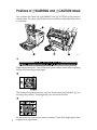


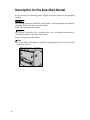


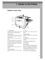
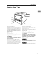
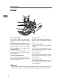

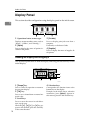
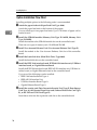
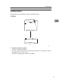
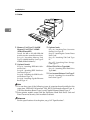
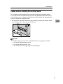

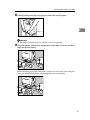
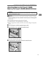


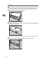


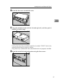


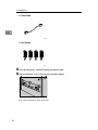
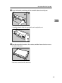

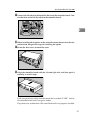
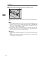
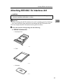
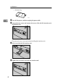
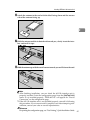
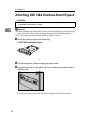
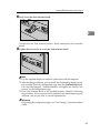
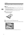

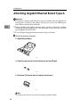
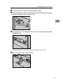
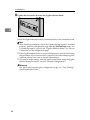
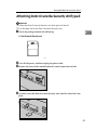
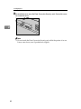


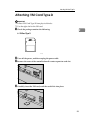
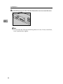
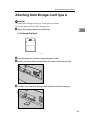
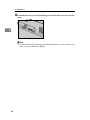

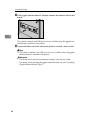
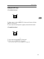


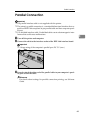

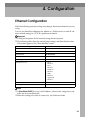
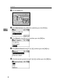
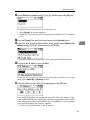
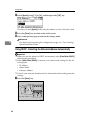

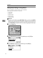
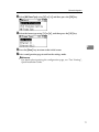

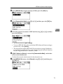


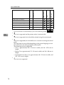

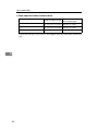
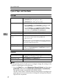
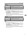

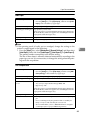
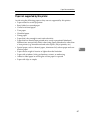
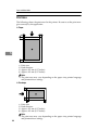
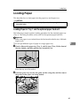
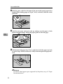

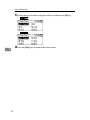
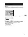

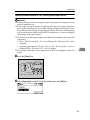

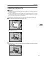
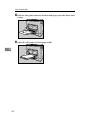


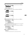

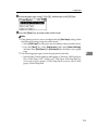
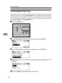
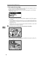

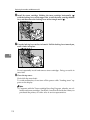


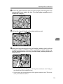
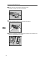
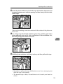

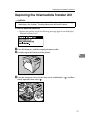
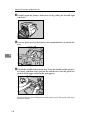

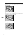

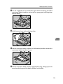
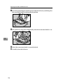

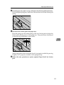
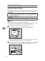
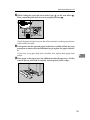
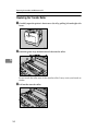
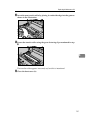
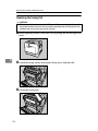
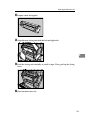
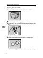
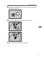


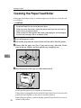
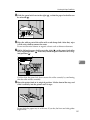

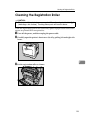

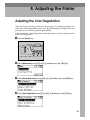

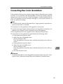
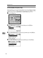
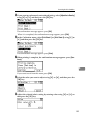
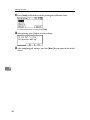

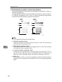
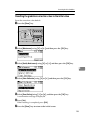
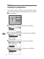
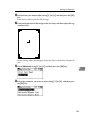
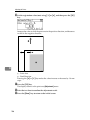
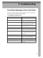


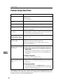

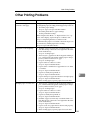
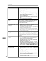
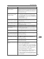

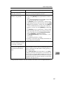


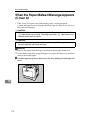
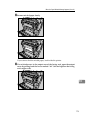

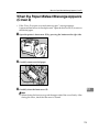


![quindi fare clic su [OK]. - Firmware Center](http://vs1.manualzilla.com/store/data/006138625_1-2938b89e5ad0c183e2d38e49a9dd0c69-150x150.png)