1
HP Workgroup System and XC Software
Installation Guide
Version 1.0
HP Part Number: A-WSXCIG-1A
Published: August 2008
Edition: 1
© Copyright 2008 Hewlett-Packard Development Company, L.P.
Confidential computer software. Valid license from HP required for possession, use or copying. Consistent with FAR 12.211 and 12.212, Commercial
Computer Software, Computer Software Documentation, and Technical Data for Commercial Items are licensed to the U.S. Government under
vendor's standard commercial license. The information contained herein is subject to change without notice. The only warranties for HP products
and services are set forth in the express warranty statements accompanying such products and services. Nothing herein should be construed as
constituting an additional warranty. HP shall not be liable for technical or editorial errors or omissions contained herein.
The information contained herein is subject to change without notice. The only warranties for HP products and services are set forth in the express
warranty statements accompanying such products and services. Nothing herein should be construed as constituting an additional warranty. HP
shall not be liable for technical or editorial errors or omissions contained herein.
UNIX is a registered trademark of The Open Group.
AMD, the AMD Arrow logo and combinations thereof, and AMD Opteron are trademarks of Advanced Micro Devices, Inc.
Intel, Pentium, Xeon, Intel Inside, and the Intel Inside logo are trademarks or registered trademarks of Intel Corporation or its subsidiaries in the
United States and other countries.
Table of Contents
About This Document.........................................................................................................9
Intended Audience.................................................................................................................................9
Document Organization.........................................................................................................................9
Typographic Conventions......................................................................................................................9
Documentation Updates and Release Notes........................................................................................10
HP Encourages Your Comments..........................................................................................................10
1 HP Workgroup System Overview...............................................................................11
1.1 HP Workgroup System Views.........................................................................................................11
2 Hardware Prerequisites...............................................................................................13
2.1 Hardware Preinstallation Checklist................................................................................................13
2.2 Firmware Requirements..................................................................................................................13
3 Hardware Setup...........................................................................................................15
3.1 Unpack the Enclosure......................................................................................................................15
3.2 Installing and Starting Up the Hardware........................................................................................17
3.2.1 Setting IP Addresses................................................................................................................17
3.2.2 Setting Boot Order...................................................................................................................19
3.2.3 Setting Up iLO.........................................................................................................................19
3.2.4 Enabling Telnet Access............................................................................................................20
3.2.5 Setting the Power Regulator....................................................................................................20
3.2.6 Configuring Smart Array........................................................................................................20
4 Software Prerequisites..................................................................................................23
4.1 Software Preinstallation Checklist..................................................................................................23
4.2 Downloading XC Software Patches.................................................................................................24
4.3 Copying the XC.lic File to Your Laptop.......................................................................................24
4.4 Associating the Enclosure DVD to the Head Node........................................................................25
5 XC Software Installation..............................................................................................27
5.1 Booting the DVD.............................................................................................................................27
5.2 Running the cluster_prep Command........................................................................................28
5.3 Installing Patches from Your Laptop...............................................................................................29
5.4 Putting the License Key File in the Correct Location......................................................................30
5.5 Running the discover Command................................................................................................30
5.6 Running the cluster_config Command...................................................................................31
5.7 Running the startsys Command................................................................................................34
5.8 Configuring the SNMP Trap...........................................................................................................34
5.9 LSF Post-Configuration Tasks.........................................................................................................35
5.10 Verifying LSF-HPC with SLURM..................................................................................................35
5.11 Running the OVP to Verify Software and Hardware Components..............................................36
5.12 Nagios Web Interface.....................................................................................................................37
5.13 The nrg Command........................................................................................................................37
5.14 Creating a Baseline Copy of the Database.....................................................................................38
5.15 Creating a Baseline Report of the System Configuration..............................................................38
5.16 Setting Up VLAN..........................................................................................................................39
Table of Contents
3
6 Troubleshooting............................................................................................................41
6.1 Unable to Manually Set IP Addresses for the iLOs.........................................................................41
6.2 Changing External IP Addresses.....................................................................................................41
6.3 Lost Connection to the iLO.............................................................................................................42
6.4 Removing a Bad Golden Image.......................................................................................................42
6.5 Lost Terminal Window When in the IRC........................................................................................43
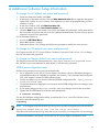
A Additional Software Setup Information.....................................................................45
B Additional Hardware Setup Information....................................................................47
B.1 HP Workgroup System Specifications............................................................................................47
B.1.1 Thermal Stabilization..............................................................................................................47
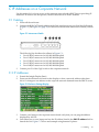
C IP Addresses on a Corporate Network.....................................................................49
C.1 Cabling............................................................................................................................................49
C.2 IP Addresses...................................................................................................................................49
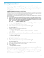
D Configure sendmail..................................................................................................51
Glossary............................................................................................................................53
Index.................................................................................................................................57
4
Table of Contents
List of Figures
1-1
1-2
1-3
3-1
3-2
3-3
3-4
3-5
3-6
3-7
4-1
5-1
C-1
C-2
C-3
Example Front View......................................................................................................................11
Enclosure Bay Numbering............................................................................................................12
Example Rear View.......................................................................................................................12
Opening the Top of the Cardboard Box........................................................................................15
Removing the Box.........................................................................................................................15
Removing the Ramp and Front Cushion......................................................................................16
Attaching the Ramp.......................................................................................................................16
Rolling the Unit Down the Ramp..................................................................................................17
Rolling the Unit to the Installation Location.................................................................................17
Interconnect Switch.......................................................................................................................18
DVD Drive.....................................................................................................................................25
IRC Virtual Media Screen..............................................................................................................29
Interconnect Switch.......................................................................................................................49
Enclosure Settings Display............................................................................................................49
OA IP Address...............................................................................................................................50
5
List of Tables
2-1
B-1
B-2
6
HP BladeSystem c-Class Firmware and Management Tools Upgrades.......................................14
HP Workgroup System Specifications..........................................................................................47
Thermal Stabilization Specification...............................................................................................47
List of Tables
List of Examples
5-1
5-2
5-3
6-1
6-2
6-3
Sample XC.lic File......................................................................................................................30
cluster_config Command Output 1.......................................................................................32
cluster_config Command Output 2.......................................................................................33
Contents of network-scripts File............................................................................................41
Modify Database...........................................................................................................................42
Sample netinfo File....................................................................................................................42
7
8
About This Document
This document describes how to set up the hardware and install the XC software on your HP
Workgroup System.
IMPORTANT: This document assumes that you are installing the XC Software Version 3.2.1
from a DVD with a valid license key on a new Cluster Platform Workgroup System which consists
of a new HP BladeSystem c3000 enclosure that has no external network connection during initial
setup and contains the following:
• Eight or less factory-installed server blades with current firmware and no operating system
installed
• A single GbE2c Ethernet switch to which you will connect a Windows laptop to access the
Onboard Administrator (OA)
• An internal DVD drive
Intended Audience
This document is intended for customers and system administrators experienced in the use of
high-performance clusters. Certain operations described in this document, if performed incorrectly,
can cause system crashes and loss of data. If you are not familiar with installing and using
high-performance clusters, HP recommends that you contact HP Global Services. This document
is also intended for HP service representatives and other persons trained to install
High-Performance Computing Cluster Platform products. Such persons are expected to
understand the hazards of working in this environment and to take suitable precautions to
minimize danger to themselves and others.
Document Organization
This document is organized as follows:
Chapter 1
Chapter 2
Chapter 3
Chapter 4
Chapter 5
Chapter 6
Appendix A
Appendix B
Appendix C
Appendix D
Provides an overview of the HP Workgroup System configuration described
in this document, and what you will have when you complete the procedures
described in this document.
Provides hardware preinstallation procedures.
Provides hardware setup procedures for unpacking, installing, and starting up.
Provides software preinstallation procedures.
Provides software installation procedures for XC System Software.
Provides troubleshooting information.
Provides additional software setup information.
Provides additional information about the hardware setup, such as system
specifications and thermal stablization.
Provides additional information about how to set up IP addresses on a corporate
network..
Provides information about how to configure the LSF sendmail program.
Typographic Conventions
This document uses the following typographical conventions:
%, $, or #
audit(5)
A percent sign represents the C shell system prompt. A dollar
sign represents the system prompt for the Bourne, Korn, and
POSIX shells. A number sign represents the superuser prompt.
A manpage. The manpage name is audit, and it is located in
Section 5.
Intended Audience
9
Command
Computer output
Ctrl+x
ENVIRONMENT VARIABLE
[ERROR NAME]
Key
Term
User input
Variable
[]
{}
...
|
WARNING
CAUTION
IMPORTANT
NOTE
A command name or qualified command phrase.
Text displayed by the computer.
A key sequence. A sequence such as Ctrl+x indicates that you
must hold down the key labeled Ctrl while you press another
key or mouse button.
The name of an environment variable; for example, PATH.
The name of an error, usually returned in the errno variable.
The name of a keyboard key. Enter and Return both refer to the
same key.
The defined use of an important word or phrase.
Commands and other text that you type.
The name of a placeholder in a command, function, or other
syntax display that you replace with an actual value.
The contents are optional in syntax. If the contents are a list
separated by |, you must choose one of the items.
The contents are required in syntax. If the contents are a list
separated by |, you must choose one of the items.
The preceding element can be repeated an arbitrary number of
times.
Indicates the continuation of a code example.
Separates items in a list of choices.
A warning calls attention to important information that if not
understood or followed results in personal injury.
A caution calls attention to important information that if not
understood or followed results in data loss, data corruption, or
damage to hardware or software.
This alert provides essential information to explain a concept or
to complete a task.
A note contains additional information to emphasize or
supplement important points of the main text.
Documentation Updates and Release Notes
Documentation updates and release notes (if applicable) are provided on the HP High Performance
Computing documentation website at: http://www.docs.hp.com/en/highperfcomp.html.
Use the release date of a document to determine that you have the latest version.
HP XC System Software documentation is available at: http://www.docs.hp.com/en/linuxhpc.html.
HP Encourages Your Comments
HP encourages your comments concerning this document. We are committed to providing
documentation that meets your needs. Send any errors found, suggestions for improvement, or
compliments to:
[email protected]
Include the document title, manufacturing part number, and any comment, error found, or
suggestion for improvement you have concerning this document.
10
1 HP Workgroup System Overview
The HP Workgroup System is delivered to you factory assembled and ready for deployment.
HP Workgroup System solutions offer a choice of HP ProLiant c-Class BladeSystem half-height
server blades with either Intel® Xeon™ or AMD Opteron™ processors. One server blade in the
configuration is designated as the head node, which you can configure separately from the
remaining server blades (compute nodes) in the enclosure. The head node can also be used for
preprocessing, postprocessing, and computational workload. Compute nodes are normally used
for application computation rather than administrative tasks.
NOTE: A hardware configuration can contain a mixture of Opteron and Xeon nodes, but not
Itanium nodes.
The HP Workgroup System is comprised of a single-cabinet cluster containing a variety of
components installed to meet the following specifications:
• A single Onboard Administrator (OA) module
• Up to eight half-height server blades
• A shared administration/Gigabit Ethernet network
• SB40 storage blade (optional)
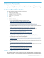
The software option described in this document is HP XC System Software. It is not preinstalled.
Installation procedures are included in this document in Chapter 5 (page 27). When you are
done, the HP XC System Software will be fully installed, configured, and operational.
1.1 HP Workgroup System Views
The HP Workgroup System ships with the server blades and all of the factory integrated modules
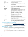
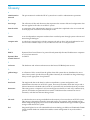
installed. Figure 1-1 shows an example front view of the HP Workgroup System.
Figure 1-1 Example Front View
The following list describes the callouts in Figure 1-1:
1. DVD optical drive
2. HP ProLiant BL260c, BL460c, or BL465c half-height server blades (eight)
3. Redundant OA module slot (reserved)
4. HP Insight Display
5. OA module
1.1 HP Workgroup System Views
11
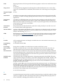
IMPORTANT:
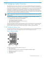
Be sure there is a blade in Bay 1. See Figure 1-2 for enclosure bay numbering.
Figure 1-2 Enclosure Bay Numbering
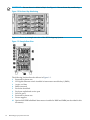
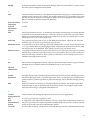
Figure 1-3 shows an example rear view of the HP Workgroup System.
Figure 1-3 Example Rear View
The following list describes the callouts in Figure 1-3:
1.
2.
3.
4.
5.
6.
7.
8.
9.
10.
12
Reserved for future use
HP Gigabit Ethernet switch installed in interconnect module bay 1 (IMB1)
Active cool fans
IMB2 (reserved)
Enclosure downlink
Enclosure uplink and service port
iLO/OA port 1
Reserved for future use
Power supplies
Optional 4X DDR InfiniBand Interconnect installed in IMB3 and IMB4 (not described in this
document)
HP Workgroup System Overview
2 Hardware Prerequisites
Gather the following information before starting the installation process. HP recommend that
you download all device drivers, firmware, and documentation to your laptop before you begin
the software installation process.
2.1 Hardware Preinstallation Checklist
You need the following items to install your hardware:
•
•
•
•
•
•
2 RJ45 CAT5 patch cables
A laptop connected to the switch
110 power cord with C13/C14 plug
A box cutter or pocket knife
Gloves
Protective eye wear
•
Hardware Documentation
— HP XC System Software Hardware Preparation Guide at:
http://docs.hp.com/en/A-XCHWP-321/A-XCHWP-321.pdf
—
—
—
All product manuals for HP BladeSystem c3000 Enclosures
All product manuals for HP BladeSystem c-Class Onboard Administrator
HP Cluster Platform Workgroup System and Cluster Platform Express Overview and Hardware
Installation Guide at:
http://www.docs.hp.com/en/A-CPCPE-1D/A-CPCPE-1D-121707.pdf
—
HP Cluster Platform Workgroup System Tower Hardware Installation Guide at:
http://www.docs.hp.com/en/A-CPWST-1B/A-CPWST-1B.pdf
—
HP Cluster Platform Site Preparation Guide at:
http://www.docs.hp.com/en/A-CPSPG-1D/A-CPSPG-1D.pdf.
—
HP BladeSystem c3000 QuickSpecs at:
http://h18004.www1.hp.com/products/quickspecs/12790_div/12790_div.html
—
HP BladeSystem c3000 Enclosure Specifications at:
http://h18004.www1.hp.com/products/blades/components/enclosures/c-class/c3000/
specifications.html
—
HP BladeSystem c3000 Enclosure and c3000 Tower Enclosure Maintenance and Service Guide
at:
All product manuals for HP BladeSystem c3000 Enclosures
—
HP BladeSystem c3000 Enclosure Setup and Installation Guide available online from a link
at:
All product manuals for HP BladeSystem c3000 Enclosures
—
HP XC Systems with HP Server Blades and Enclosures HowTo at:
http://www.docs.hp.com/en/10077/blade_howto.pdf
2.2 Firmware Requirements
HP installs the current version of firmware on Cluster Platform hardware components before
shipping your order. To verify the firmware version for a component, see the following documents:
2.1 Hardware Preinstallation Checklist
13
•
•
For information on displaying the installed version of firmware, see the service guide for
the hardware component.
For the supported firmware versions, see the HP XC System Software: Master Firmware Tables
Version 3.2.1 available online at:
http://docs.hp.com/en/A-XCFM3-21A/index.html
To upgrade firmware, follow these steps:
1. Go to the web address specified in Table 2-1 to download the firmware.
2. For information on how to upgrade firmware, see the service guide for the hardware
component.
.
CAUTION: . Before installing or upgrading firmware on HP XC System components, see HP
XC System Software: Master Firmware Tables Version 3.2.1. Important guidelines and firmware
versions that are known to be incompatible are detailed in the document. Upgrading firmware
to a version other than those specified in HP XC System Software: Master Firmware Tables Version
3.2.1 can cause problems.
Table 2-1 HP BladeSystem c-Class Firmware and Management Tools Upgrades
Component
Web Address
HP ProLiant Server Blades
BL260c
BL460c
c-Class Firmware and Upgrades. Click Server Blade Firmware and
Drivers.
BL465c
HP c-Class BladeSystem Enclosure Components and Switches
Onboard Administrator (OA)
HP ProLiant Integrated Lights Out 2 (iLO
2)
Server Blade mezzanine cards (if
applicable)
HP BladeSystem Integrated Manager
c-Class Firmware and Upgrades. Click each of the applicable downloads.
HP Systems Insight Manager
HP Insight Control Environment for
BladeSystem
HP Insight Control Linux Edition
GbE2c Ethernet Switch
14
Hardware Prerequisites
GbE2c Ethernet Blade Switch. Click Software & Drivers, and search for
your operating system.
3 Hardware Setup
For more information about the HP Workgroup System specifications and thermal stabilization,
see Appendix B (page 47).
3.1 Unpack the Enclosure
To unpack and remove the HP Workgroup System from a pallet, follow these steps:
1.
Move the pallet to the installation location and leave several feet of space to move around
the pallet.
NOTE: Carton graphics provide instructions on how to unpack the HP Workgroup System
and to open the top of the box first.
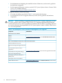
2.
Open the top of the cardboard box. (Callout 1, Figure 3-1)
Figure 3-1 Opening the Top of the Cardboard Box
3.
4.
Remove the two boxes containing the security bezel, power cords, and other accessories.
(Callout 2, Figure 3-1)
Remove the cushions from the top of the unit (Callout 3, Figure 3-1) and the cardboard box.
(Callout 1, Figure 3-2)
Figure 3-2 Removing the Box
3.1 Unpack the Enclosure
15
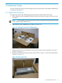
5.
Remove the front section of the bottom cushion (Callout 2) and the ramp. (callout 1,
Figure 3-3)
Figure 3-3 Removing the Ramp and Front Cushion
6.
Attach the ramp to the plywood deck using the hook-and-loop. (Callout 1, Figure 3-4)
NOTE:
Box clamps must be folded out of the way to lay the ramp down.
Figure 3-4 Attaching the Ramp
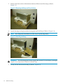
WARNING! The HP Workgroup System weighs 300+ pounds. To avoid injury, you might
require a second person to assist you with this step.
7.
16
Gently roll the unit down the ramp. (Callout 1, Figure 3-5)
Hardware Setup
Figure 3-5 Rolling the Unit Down the Ramp
Figure 3-6 Rolling the Unit to the Installation Location
8.
Plug the unit into a power source.
3.2 Installing and Starting Up the Hardware
Familiarize yourself with the back of the c3000 enclosure and identify the OA interface port and
the HP GbE2c Ethernet switch. See Figure 1-3 (page 12). Verify that there is a blade in bay 1. See
Figure 1-2 (page 12) to identify bay numbers. For information about how to move blades in the
enclosure, see the HP BladeSystem c3000 Tower Enclosure Setup and Installation Guide .
http://bizsupport.austin.hp.com/bc/docs/support/SupportManual/c01310294/c01310294.pdf
3.2.1 Setting IP Addresses
Before setting the IP addresses, verify that your c3000 is not connected to the corporate network.
Make sure you have downloaded the information recommended in Chapter 2 (page 13).
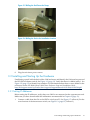
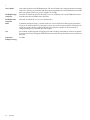
1.
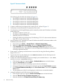
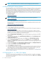
Connect a cable from the OA to the GbE2c switch port 23. See Figure 3-7 callout 4. (For the
exact location of the interconnect switch, see Figure 1-3 (page 12) Callout 2.)
3.2 Installing and Starting Up the Hardware
17
Figure 3-7 Interconnect Switch
The following list describes the callouts in Figure C-1:
1. Port 20 RJ-45 connector for 10/100/1000 Mb uplink
2. Port 21 RJ-45 connector for 10/100/1000 Mb uplink
3. Port 22 RJ-45 connector for 10/100/1000 Mb uplink
4. Port 23 RJ-45 connector for 10/100/1000 Mb uplink
5. Port 24 RJ-45 connector for 10/100/1000 Mb uplink
2.
3.
4.
Connect a cable from your laptop to the switch port 21. Callout 2 Figure C-1
Verify that no external network is connected to the switch.
Use the menus on the Insight Display panel to manually set the static IP address and subnet
mask for the OA.
• IP address of the OA: 172.31.32.1
• IP address of the installation PC: 172.31.32.20
• Netmask for the PC: 255.255.0.0
• Starting IP address for enclosure bay IP addressing: 172.31.15.1 (this uses the addresses
from 172.31.15.1 to 172.31.15.16)
5.
On your laptop or PC, manually set a static IP address for the NIC in the same subnet as the
IP address you set for the OA.
a. On your PC, go to Start → Control Panel → Network Connections.
b. Right-click Local Area Connection and choose Internet Protocol (TCP/IP).
c. Click Properties and choose Use the Following IP addresses and enter the IP
addresses listed below. Remember to reset your laptop after installation if you need to
access the corporate network.
6.
From your PC or laptop, use the browser to access the OA using the following address:
https://172.31.32.1
7.
8.
9.
18
Log in to the OA. Use the default user name Administrator and the default password
shown on the tag affixed to the OA.
Create a new user name and password. For example, you can make the User name: Root,
and the Password: Test1234 as follows:
a. Click the plus sign (+) to open the User → Authentication menu in the left frame.
b. Select the Local Users and click New.
c. Add local user information including a password and confirmation.
d. Change privilege level to Administrator and make sure that the User Enabled is checked.
e. Check Onboard Administrator Bays under User Permissions. Then click the Update
User button.
f. Test by signing out of the OA and signing in with the new account information.
Assign IP addresses to all iLO2 devices in the enclosure:
a. Click the plus sign (+) to open the Enclosure Settings menu in the left frame.
b. Select the Enclosure Bay IP Addressing menu item.
c. Select the check box to Enable Enclosure Bay IP Addressing.
Hardware Setup
d.
e.
For Bay 1, specify the IP addresses 172.31.15.1. Click Autofill to populate the remaining
IP addresses.
Wait 60 seconds for the assignments to take effect, then click Apply to save your settings.
3.2.2 Setting Boot Order
To set the boot order for the head node and compute nodes, assuming Bay 1 is the head node,
follow these steps:
1.
2.
3.
In the left frame of the OA browser window, click the plus sign (+) next to Device Bays to
display the list of nodes contained in the enclosure.
Click the link to the first hardware model in the list. Wait a few seconds until the frame to
the right is populated with node-specific information.
Click the Boot Options tab.
Select a boot device and use the up and down arrows on the screen to position the device
so that it matches the boot order listed below.
NOTE:
All nodes except the head node must have the same boot order.
Set the following boot order on the head node:
1.
2.
3.
4.
5.
USB
Floppy
CD
Hard Disk
PXE NIC1
Set the following boot order on all nodes except the head node:
1.
2.
3.
4.
5.
USB
Floppy
CD
PXE NIC 1
Hard Disk
Clik Apply.
3.2.3 Setting Up iLO
Perform steps in Section 3.2.3, Section 3.2.4, Section 3.2.5, and Section 4.4 for the head node, then
repeat Section 3.2.3, Section 3.2.4, and Section 3.2.5 for each compute node.
To add new identical user names and passwords for OA and iLO:
1.
2.
From the OA, click (+) Device Bays. Under the hardware model, click iLO.
In the body of the main window, click Web Administration to open the iLO2 utility in a
new window.
NOTE:
3.
4.
5.
Turn off popup blocking so the window can open.
In the new window, click Administration.
In the left frame, click User Administration.
Click New. Create a new iLO2 user name and password, which must match the user name
and password you set on the OA. Do not use any special characters as part of the password.
Use this user name and password whenever you need to access the console port with the
telnet cp-nodename command, or with the ssh cp-codename command.
6.
Save user information.
3.2 Installing and Starting Up the Hardware
19
NOTE: The OA automatically creates user accounts for itself (prefixed with the letters OA)
to provide single sign-on capabilities. Do not remove these accounts. The OA also creates
iLO accounts on each blade for its own use.
3.2.4 Enabling Telnet Access
1.
2.
Under the hardware model, click iLO.
In the body of the main window, click Web Administration to open the iLO2 utility in a
new window.
NOTE:
3.
4.
5.
6.
Turn off popup blocking so the window can open.
In the new window, click Administration.
In the left frame, click Access.
Click the control to enable Telnet Access.
Click Apply to save the settings.
3.2.5 Setting the Power Regulator
Select an individual blade. Click the Power Management tab and make the following settings:
1.
2.
3.
4.
5.
6.
For every node except the head node, select No to Automatically Power On Server because
you do not want to automatically turn on power to the node.
Click Submit.
In the left frame, click Settings.
Select Enable HP Static High Performance Mode.
Click Apply to save the settings.
For the head node, continue to Section 4.4. For compute nodes, return to Section 3.2.3 and
repeat Section 3.2.3, Section 3.2.4, and Section 3.2.5 for each compute node.
3.2.6 Configuring Smart Array
This section is for configurations containing SB40 storage blades.
Configure disks into the smart array from the remote graphics console. You must add the disk
or disks to the smart array before attempting to image the node.
To set up the smart array device, click Remote Console on the virtual console page of the iLO2
Web Administrator Utility, then follow these steps:
1.
2.
3.
4.
5.
Click Integrated Remote Console to open a remote console window which provides access
to the graphics console virtual media and power functions.
In the remote console window, click Power.
Click Momentary Press.
Wait a few seconds for the power on phase to begin. Click the MB1 mouse button in the
remote console window to put the pointer focus in this window so that your keyboard
strokes are recognized.
Watch the screen carefully during the power-on self-test phase, and press the F8 key when
you are prompted to configure the disks into the smart array. Select View Logical Drives
to determine if a logical drive exists. If a logical drive is not present, create one.
If you create a logical drive, exit the Smart Array utility and power off the node. Do not let
it try to boot up.
For more information about specific smart array configurations, see the documentation that
came with your HP ProLiant server .
20
Hardware Setup
6.
7.
8.
Use the virtual power functions to turn off power to the server blade.
Close the iLO2 utility web page.
Repeat this procedure from every active OA and make the same settings for each server
blade in each enclosure.
3.2 Installing and Starting Up the Hardware
21
22
4 Software Prerequisites
Have the following information ready before starting the installation process. Because it is
assumed that you will not have an external network connection during the XC Software
installation process, we recommend that you download all passwords, the XC.lic file, device
drivers, firmware, XC patches, and documentation to your laptop before you begin the software
installation process.
4.1 Software Preinstallation Checklist
•
Passwords
TIP: For the purposes of this guide, the following values are used:
user:
root
password:
Test1234
The following lists default factory settings. To change these settings, see Appendix A
(page 45) .
—
—
—
Administrator user name and password are supplied with the HP Workgroup System.
Root user password
OA and iLO user name and password must be the same. The OA user name and
administrator password are on the tag attached to the OA. The iLO defaults are:
user:
Admin
password:
Admin
NOTE: The database, Nagios, and LSF administrator passwords are defined during the
XC Software installation process.
•
IP Addresses
— You need a network cable to connect a laptop directly to the OA to assign IP addresses.
— You need IP addresses for the head node external network, gateway, and net mask. If
you do not have this information, example default values are provided in the XC software
installation procedures.
•
Software Documentation
— HP XC System Software Installation Guide at:
http://docs.hp.com/en/A-XCINS-321/A-XCINS-321.pdf
—
HP XC System Software Master Firmware List at:
http://docs.hp.com/en/A-XCFM3-21A/A-XCFM3-21A.pdf
—
Information
◦
You need the cluster name (also referred to as the node name prefix). The default
is n. This can be changed during the cluster_prep process of the XC Software
installation.
◦
The time zone for the system.
◦
Have an available file containing your license key.
You also need the following items:
• A serial cable required for VLAN setup
• The XC 3.2.1 installation DVD
4.1 Software Preinstallation Checklist
23
NOTE:
An internal DVD drive is included in the HP Workgroup System enclosure.
4.2 Downloading XC Software Patches
For each supported version of the HP XC System Software, HP releases all Linux security updates
and HP XC software patches on the HP IT Resource Center (ITRC) website. To determine if
software patches are available, go to the product-specific location on the ITRC. You must download
all available patches and updated RPM packages for the XC Software installation now and save
to your laptop to be prepared for “Installing Patches from Your Laptop” (page 29) during the
XC Software installation.
• HP ITRC website:
http://www.itrc.hp.com
NOTE:
You must register for an account and password to download patches at
http://www.itrc.hp.com.
•
HP XC System Software Release Notes for Version 3.2.1
Because the HP XC System Software Release Notes are updated periodically, and are only
available online:
http://www.docs.hp.com/en/linuxhpc.html
To download the XC patches, follow these steps:
1.
2.
Create a temporary directory on your laptop.
Go to the ITRC website and register as an Americas/Asia Pacific or European customer at:
http://www.itrc.hp.com/
When you supply information about yourself and your corporation, an ITRC user ID is
assigned to you, and you supply your own password. Remember this user ID and password
because you must use it whenever you download a patch.
3.
From the Registration Confirmation window, select the option to go directly to the ITRC
home page.
4. From the ITRC home page, select patch/firmware database from the maintenance and
support (hp products) list.
5. From the Patch/Firmware database page, select Linux under find individual patches.
6. From the Search for patches page in Step 1 of the Search utility, select Vendor and
Version, select hpxc as the vendor and select the HP XC version that is appropriate for the
cluster platform.
7. In step 2 of the Search utility, How would you like to search?, select Browse Patch List.
8. In step 4 of the Search utility, Results per page?, select all.
9. Click search>>> to begin the search.
10. Download all patches that are available for the cluster platform into the temporary directory
you created in Step 1. If you are unable to retrieve the files from this website, contact the
HP XC Support team at the following email address: [email protected].
The downloaded patches are installed during the XC Software installation in “Installing Patches
from Your Laptop” (page 29).
4.3 Copying the XC.lic File to Your Laptop
The HP XC license key file was emailed to you. You must copy the XC.lic file to your laptop
to use later when installing the XC Software. Use a text editor to remove all ^M characters (Ctrl-m)
from the file, if necessary.
24
Software Prerequisites
If you have not received the license key file, contact your HP representative.
4.4 Associating the Enclosure DVD to the Head Node
To associate the enclosure DVD to the head node (Bay 1), follow these steps:
1.
2.
3.
4.
5.
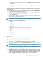
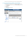
From the OA left navigation frame, go to Enclosure Settings. (Figure 4-1)
Go to DVD drive.
Check 1.
Choose DVD.
Connect to the enclosure DVD.
Figure 4-1 DVD Drive
4.4 Associating the Enclosure DVD to the Head Node
25
26
5 XC Software Installation
For more details on the following steps, see the HP XC System Software Installation Guide, Section
2.3.2.
NOTE:
The XC Software installation process may take as long as two hours to complete.
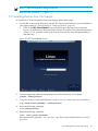
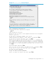
5.1 Booting the DVD
1.
Start the installation, leaving the browser on the laptop connected to the OA.
NOTE: This document assumes that the internal DVD drive will be used. However, the
boot process can be much faster if you use an external drive attached to the head node with
a dongle.
2.
3.
4.
5.
Open the Integrated Remote Console (IRC) to Bay 1 (head node). (Figure 4-1 (page 25))
Turn off the power to the head node.
Turn on the power to the head node.
The Boot prompt response you enter is server type dependent.
For HP Proliant BL460c:
Boot: linux ks=hd:scd0/ks.cfg
For HP Proliant BL465c:
Boot: linux ks=hd:scd0/ks.cfg pci=nommconf
6.
Select first disk, a global file system, and no RAID. You must choose your own time zone.
For example:
Select the disk for the installation: 1
Do you want to create the XC global file system?: Y
Would you like XC to use the default partition table?: d
Enter "C" to continue C
Time Zone:timezone
Root Password:Test1234
7.
8.
After the head node reboots, log in as root.
Open a terminal window.
Right-click and choose Terminal.
Or
Click Applications→System Tools→Terminal to open a terminal window.
5.1 Booting the DVD
27
5.2 Running the cluster_prep Command
IMPORTANT: Some HP XC patches might need to be run before cluster_prep. Check the
Readme file of all patches for more details.
IMPORTANT: If you are restarting the cluster_prep procedure, you must remove the database
on the headnode with the # reset_db command.
NOTE: You can access the head node by using the IRC or by using ssh with PuTTY to connect
to the IP address of the head node.
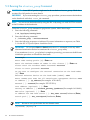
To run the cluster_prep command to prepare the system, follow these steps:
1.
Enter the following command:
# cd /opt/hptc/config/sbin
2.
Enter the following command:
# ./cluster_prep --enclosurebased
3.
Enter the following responses as indicated. For more information on reponses, see Table
3–1 in the HP XC System Software Installation Guide.
IMPORTANT: Do not press Ctrl-c or Ctrl-d, enter the kill command, or use any other
abnormal termination method to terminate the cluster_prep utility.
If you terminate cluster_prep before it completes processing, you must use the Kickstart
installation procedure to reinstall the head node.
For example:
Enter node naming prefix [n]: Enter or n
Enter the maximum number of nodes in this cluster [ ]: Enter or 8
Please enter the Database Admin Password: Test1234
Please re-enter password: Test1234
Do you want to configure the external connection on the head node?
[Y]: Enter
External Ethernet device on the head node [undef]: eth1
Enter common user name for all console port management devices: root
IP address [ ]: ip_address (For example: 16.118.48.57)
Netmask [ ]: netmask (For example: 255.255.252.0)
IPv6 address (optional) [ ]: Enter
Gateway IP address [ ]: network_gateway_ipaddress (For example: 16.118.48.1)
MTU value (optional) [ ]: Enter
IP address for DNS name server [ ]: dns_name server(If unknown, Enter)
Search path [ ]: dns_searchpath (if unknown, Enter)
.
NOTE:
Be sure to use a period after the last domain name.
[P]roceed, [R]etry: P
28
XC Software Installation
NOTE:
Enter the letter R to change a response.
Restarting network ... done
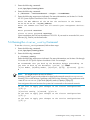
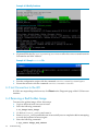
5.3 Installing Patches from Your Laptop
To install the XC Software patches from your laptop, follow these steps:
1.
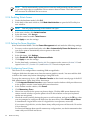
Use the IRC to mount the directory with the XC Software patches that you downloaded on
your laptop earlier in “Downloading XC Software Patches” (page 24).
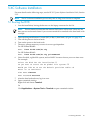
• Click on the IRC Virtual Media icon on the ILO2 tab at the top of the screen (see
Figure 5-1) and browse to select the folder with the XC patches. This creates the directory
/media/iLO2_FOLDER on the head node and mounts the selected laptop folder to
that directory.
Figure 5-1 IRC Virtual Media Screen
2.
Create a temporary patch download directory on the head node. For example:
# mkdir /home/patches
3.
Copy the contents of the patch file from /media/iLO2 to /home/patches as follows:
# cp /media/iLO2_FOLDER/* /home/patches
4.
Enter the following command:
# cd /home/patches
5.
Enter the following command:
# tar -xvzf patch_filename
File extensions are typically .tar.gz, and .tgz. This creates subdirectories in /home/
patches.
5.3 Installing Patches from Your Laptop
29
6.
To install the patches, change into each directory using cd. Follow the instructions in the
Readme file.
For more information on how to install the patches, see the README file in each directory.
5.4 Putting the License Key File in the Correct Location
The license key information must already be saved into a file named XC.lic on your laptop.
See “Copying the XC.lic File to Your Laptop” (page 24).
NOTE: The sample XC.lic shown in Example 5-1 is included in this document for illustrative
purposes only; it is not intended for use and is not valid for the system.
Example 5-1 Sample XC.lic File
Hewlett Packard Company -- This message in its entirety may be placed into
your license file. Use an ASCII Text Editor to avoid introducing characters
which will invalidate the license file. If you have any problems installing
this license key, contact the parties listed on the associated license
documentation or web site.
SERVER this_host ANY
VENDOR Compaq
USE_SERVER
INCREMENT XC Compaq 3.1 28-feb-2007 1 23BBAFCE6662c \
1.6 Task 6: Arrange for IP Address Assignments and Host Names 25
NOTICE="Authorization = BM05WHITMORE19772031 - permanent - HP \
XC System Software - BASE License"
INCREMENT XC-PROCESSORS Compaq 3.0 permanent 68 7BA7E0876F0F \
NOTICE="Date 30-Jan-2007 01:29:36 - License Number = \
LAGA4D1958DL - Qty 68 - 434066-B21 - HP XC System Software 1 \
Proc Flex License"
INCREMENT lsf_xc Compaq 6.1 permanent uncounted 8BC06464E38E \
HOSTID=ANY NOTICE="Date 30-Jan-2007 01:29:36 - License Number \
= LAGA4D1958DL - Qty 1 - p/n 5991-4844 - HP XC System Software \
- LSF License"+
To put the license key file in the correct location, follow these steps:
1.
2.
3.
4.
Login as the root user on the head node.
Mount that folder. Click on Media in the IRC. Then choose the Folder option.
Browse to the location of the license.
Copy the contents of the license file from /media/iLO2_FOLDER/ to /opt/hptc/etc/
license/XC.lic
# cp /media/iLO2–FOLDER/* /opt/hptc/etc/license/XC.lic
5.
Make sure the file permissions are set to allow only the user root to have read and write
access:
# chmod 600 /opt/hptc/etc/license/XC.lic
# ls -l /opt/hptc/etc/license/XC.lic
-rw------1 root
root
941 Oct 20 10:34 XC.lic
6.
To unmount the folder, click Media on the IRC, then click Unmount the folder.
5.5 Running the discover Command
1.
2.
30
Click (+) for Active OA and choose TCP/IP settings in the left navigation window. Write
down the MAC address of the OA (For example: 00.01.02.03.04.05:06).
Select DHCP, then Apply.
XC Software Installation
3.
Enter the following command:
# cd /opt/hptc/config/sbin
4.
Enter the following command:
# ./discover --enclosurebased --single --ic=AdminNet
5.
Enter the following responses as indicated. For more information, see Section 3.6.3 in the
HP XC System Software Installation Guide. For example:
Enter the MAC address of the OA for the enclosure in the format
xx:xx:xx:xx:xx:xx : oa_mac_address
Enter the common user name for all console port management devices:
root
Enter password: Test1234
Please re-enter password: Test1234
Upon completion, the OA has the address 172.31.32.1. If you need to access the OA, run a
browser (e.g. Firefox) on the head node.
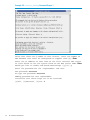
5.6 Running the cluster_config Command
To run the cluster_config command, follow these steps:
1.
Enter the following command:
# cd /opt/hptc/config/sbin
2.
Enter the following command:
# ./cluster_config
Enter the following responses as indicated. For more information, see Sections 3.8 through
3.11 in the HP XC System Software Installation Guide. For example:
HP recommends that you back up the database before proceeding. Do
you want to back up the database? (yes/no) [y]: Enter
[L]ist Nodes, [M]odify Nodes, [A]nalyze, [H]elp, [P]roceed, [Q]uit:
P
NOTE:
You might receive an error as follows:
Warning: Unable to get host by address for head node external network xxx.xxx.xxx.xxx
Warning: This could indicate a problem with DNS lookup Warning: Using null name with
name of xxx.xxx.xxx.xxx [L]ist Node [M]odify nodes [A]analyz [H]elp [P]:
You can ignore this error because the system isn't connected to the external network.
Do you want to apply your changes to the cluster configuration?
[y/n]: y
[S]ervices Config, [P]roceed, [Q]uit: P
Do you want to apply your changes to the cluster configuration?
[y/n]: y
Do you want to apply your changes to the service configuration?
[y/n]: y
5.6 Running the cluster_config Command
31
Example 5-2 cluster_config Command Output 1
Given that there are # nodes in this cluster, enter the number of
NFS daemons that shall be configured to support them [8]: Enter
Enter the IP address or host name of the first external NTP server
or leave blank to use the system clock on the NTP server node: Enter
Would you like to enable web based monitoring? ([y]/n): y
Enter the password for the 'nagiosadmin' web user:
New password: Test1234
Re-type new password: Test1234
Adding password for user nagiosadmin
Interfaces over which traps are to be received:
[0]All, [1]External, [2]Int: 0
32
XC Software Installation
Example 5-3 cluster_config Command Output 2
[O]k, [R]especify Interfaces: O
Interfaces over which traps will be accepted:
loopback
Admin
[O]k, [R]especify Interfaces:
Would you like to create a self-signed certificate for the Apache
server? ([y]/n): n
Do you want to configure SLURM? (y/n) [y]: n
SLURM configuration complete. Press 'Enter' to continue: Enter
Do you want to install LSF now? (y/n) [y]: Enter
There are two types of LSF available to install: 1. Standard LSF:
the standard Load Sharing Facility product. 2. LSF-HPC integrated
with SLURM: the LSF High Performance Computing solution integrated
with SLURM for XC. Which LSF product would you like to install (1/2)?
[2]: Enter
LSF System Name [hptclsf]: Enter
Enter the name of the Primary LSF Administrator. [lsfadmin]: Enter
Do you want to create this user now? (y/n) [y]: Enter
New UNIX password: Test1234
Retype new UNIX password: Test1234
Press 1 or Enter to install this host type: Enter
5.6 Running the cluster_config Command
33
The Golden Image will be created next. [P]roceed, [Q]uit: P
CAUTION: Do not interrupt or stop the golden image creation. Do not browse or touch
files. Doing so corrupts the golden image.
If you corrupt the golden image, use the following command to remove the base image file
(/var/lib/systemimager/images/base_image) to recover from a corrupted golden
image:
# si_rmimage base_image
Restart the cluster_config process.
5.7 Running the startsys Command
Use this procedure to start the system and propagate the golden image to all nodes. Ensure that
the power is off on all nodes except the head node. The startsys command turns on the power
to all nodes, images the nodes, and boots the nodes.
IMPORTANT: You cannot continue if the license file is not present in /opt/hptc/etc/license.
For information, see “Putting the License Key File in the Correct Location” (page 30)
IMPORTANT: The startsys command cannot power nodes on or off if the XC password is
incorrect because the iLO always prompts for the password. To verify the XC database password,
run the following command:
# /opt/hptc/hpls-pwr/mod/getauth
1.
Enter the following command:
# setnode --resync --all
2.
To image and boot the system in one step, enter the following command:
# startsys --image_and_boot
3.
Make sure all the nodes are up. Enter the following command:
# power --status
Troubleshooting file system mounting
You might experience a mount failure when the nodes image, boot, and attempt to NFS mount
the /hptc_cluster file system. Run the following commands on the head node to restart nfs
and rerun node configuration scripts and restart services on all other nodes:
1.
2.
3.
4.
# service nfs restart
# pdsh -a touch /var/hptc/nconfig.1st
# stopsys
# startsys
5.8 Configuring the SNMP Trap
To configure the SNMP trap destination for the enclosure, follow these steps:
1.
Enter the following command:
# manage_enclosure addtrap
[root@n1 sbin]# manage_enclosure addtrap
n-enc09CN8734016G: Added SNMP trap receiver destination 172.31.15.240
You have new mail in /var/spool/mail/root
[root@n1 sbin]#
34
XC Software Installation
2.
Enter the following command:
# manage_enclosure listtrap
[root@n1 sbin] manage_enclosure listtrap
n-enc09CN8734016G:
172.31.15.240
[root@n1 sbin]#
5.9 LSF Post-Configuration Tasks
To finish the configuration, follow these steps:
1.
2.
Login as root user on the head node.
Set up the LSF environment by sourcing the LSF file as follows:
# . /opt/hptc/lsf/top/conf/profile.lsf
3.
Verify that the LSF profile file has been sourced by finding an LSF command:
# which lsid
[root@n1 sbin]# . /opt/hptc/lsf/top/conf/profile.lsf
[root@n1 sbin]# which lsid
/opt/hptc/lsf/top/6.2/linux2.6-glibc2.3-x86-64-slurm/bin/lsid
[root@n1 sbin]#
4.
(Optional) If you assigned two or more nodes with the resource_management role and
want to enable LSF failover, enter the following command:
# controllsf enable failover
5.
Determine the node on which the LSF daemons are running:
# controllsf show current
[root@n1 sbin]# controllsf show current
LSF is currently running on n1, and assigned to node n1.
[root@n1 sbin]#
6.
Restart the LIM daemon:
# lsadmin limrestart
[root@n1 sbin]# lsadmin limrestart
Checking configuration files ...
No errors found.
Restart LIM on <lsfhost.localdomain> ...... done
[root@n1 sbin]#
NOTE: Restarting the LIM daemon is required because the licensing of LSF-HPC with
SLURM occurs when the LIM daemon is started. This means that the LIM daemon is licensed
only for the processors that are actually available at that time, which might be fewer than
the total number of processors available after all of the nodes have been imaged and are up
and running.
7.
Update the LSF batch system with the latest resource information reported by SLURM:
# badmin reconfig
[root@n1 sbin]# badmin reconfig
Checking configuration files ...
No errors found.
Reconfiguration initiated
[root@n1 sbin]#
5.10 Verifying LSF-HPC with SLURM
1.
Verify that LSF-HPC with SLURM is running as follows:
5.9 LSF Post-Configuration Tasks
35
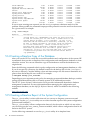
# lsid
Platform LSF HPC 6.2 for SLURM, LSF_build_date
Copyright 1992-2005 Platform Computing Corporation
My cluster name is hptclsf
My master name is lsfhost.localdomain
2.
Verify that the lsf partition exists and all nodes are in the idle state:
# sinfo
PARTITION AVAIL TIMELIMIT NODES STATE NODELIST
lsf
up infinite
8 idle n[1-8]
3.
Confirm that the ncpus value matches the expected total number of available processors:
# lshosts
HOST_NAME
type
model
lsfhost.loc SLINUX6 Opteron8
4.
cpuf ncpus maxmem maxswp server RESOURCES
16.0
60 3649M
Yes (slurm)
Verify the dynamic resource information:
# bhosts
HOST_NAME
STATUS
lsfhost.localdomai ok
JL/U
-
MAX
16
NJOBS
0
RUN
0
SSUSP
0
USUSP
0
RSV
0
See the troubleshooting information in the HP XC System Software Administration Guide if
you do not receive a status of ok from the bhosts command.
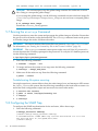
5.11 Running the OVP to Verify Software and Hardware Components
The Operation Verification Program (OVP) verifies the major HP XC software and hardware
components to provide a level of confidence that the system has been installed and configured
correctly.
The OVP performs tests to verify the following:
• The interconnect is functional.
• Network connectivity has been established.
• The administration network is operational.
• A valid license key file is installed and the license manager servers are up.
• All compute nodes are responding and are available to run applications.
• SLURM control daemons are responding and partitioning is valid if LSF-HPC with SLURM
is configured.
• CPU usage on all nodes except the head node (by default).
• Memory usage on all compute nodes except the head node (by default).
Start the Operation Verification Program
To start the OVP, follow these steps:
1.
2.
Login as the root user on the head node.
Start the OVP with no component-specific options to test the entire system:
# ovp [--verbose [--verbose]] [--timeout=0]
3.
4.
Follow along with the OVP command output.
Examine the test results to ensure that all tests passed. Test results are stored in a
date-stamped log file located in the /hptc_cluster/adm/logs/ovp directory.
Test failures and warnings are clearly reported in the log file, and it contains some
troubleshooting information. In some cases, the errors might be obvious, and the test output
is terse.
The format of the OVP log file name includes the following:
•
•
36
The internal name of the head node.
The OVP run date in MMDDYYformat.
XC Software Installation
•
The run number, which represents the number of times the OVP has been run. The run
number is not included for the first run.
For example, the log file name ovp_ n16_070607.log indicates that this is the first run
of the OVP on July 06, 2007, on head node n16.
5.
For more information about troubleshooting failed test results, see HP XC System Software
Installation Guide.
For information about verifying individual cluster components on demand, see ovp(8) and
the HP XC System Software Administration Guide.
If you receive errors or warnings from the OVP, try synchronizing the nodes:
# setnode --resync --all
5.12 Nagios Web Interface
Nagios is the system and network health monitoring application on an HP XC system. It watches
hosts and services and alerts you when problems occur or are resolved.
TIP: HP recommends that you start up the Nagios web interface now to view the network and
ensure that all hosts and services are in the green state.
To open the Nagios web page, follow these steps:
1.
2.
Open a browser on the head node.
Enter the following web address in the Address field:
https://fully_qualified_HP_XC_hostname/nagios
3.
When prompted, log in as the nagiosadmin user and specify the Nagios administrator
password.
If the hardware configuration contains less than 100 nodes, the Service Detail view provides
a good overview of the system. It lists the Nagios hosts and shows their status.
The Service Problems view is more useful for hardware configurations with hundreds or
thousands of nodes. It provides a practical overview of the system.
For more information about how to use Nagios, see the HP XC System Software Administration
Guide.
5.13 The nrg Command
The nrg command uses data collected by the Nagios utility to generate reports. Use the summary
option to display a summary of defined Nagios services and the state of those services. For
example:
# nrg --mode summary
Apache HTTPS Server
configuration
Configuration Monitor
Environment
Host Monitor
IP Assignment - DHCP
Load Average
LSF Failover Monitor
Nagios Monitor
NodeInfo
PING Interconnect
Resource Monitor
Resource Status
Root key synchronization
Sensor Collection Monitor
1-Ok
10-Ok
1-Ok
10-Ok
1-Ok
1-Ok
10-Ok
1-Ok
1-Ok
10-Ok
10-Ok
1-Ok
10-Ok
1-Ok
1-Ok
0-Warn
0-Warn
0-Warn
0-Warn
0-Warn
0-Warn
0-Warn
0-Warn
0-Warn
0-Warn
0-Warn
0-Warn
0-Warn
0-Warn
0-Warn
0-Crit
0-Crit
0-Crit
0-Crit
0-Crit
0-Crit
0-Crit
0-Crit
0-Crit
0-Crit
0-Crit
0-Crit
0-Crit
0-Crit
0-Crit
0-Pend
0-Pend
0-Pend
0-Pend
0-Pend
0-Pend
0-Pend
0-Pend
0-Pend
0-Pend
0-Pend
0-Pend
0-Pend
0-Pend
0-Pend
0-Unk
0-Unk
0-Unk
0-Unk
0-Unk
0-Unk
0-Unk
0-Unk
0-Unk
0-Unk
0-Unk
0-Unk
0-Unk
0-Unk
0-Unk
5.12 Nagios Web Interface
37
Slurm Monitor
Slurm Status
Supermon Metrics Monitor
Switch
Switch Data Collection
Syslog Alert Monitor
Syslog Alerts
System Event Log
System Event Log Monitor
System Free Space
Totals:
1-Ok
10-Ok
1-Ok
2-Ok
1-Ok
1-Ok
10-Ok
9-Ok
1-Ok
10-Ok
115-Ok
0-Warn
0-Warn
0-Warn
0-Warn
0-Warn
0-Warn
0-Warn
1-Warn
0-Warn
0-Warn
1-Warn
0-Crit
0-Crit
0-Crit
0-Crit
0-Crit
0-Crit
0-Crit
0-Crit
0-Crit
0-Crit
0-Crit
0-Pend
0-Pend
0-Pend
0-Pend
0-Pend
0-Pend
0-Pend
0-Pend
0-Pend
0-Pend
0-Pend
0-Unk
0-Unk
0-Unk
0-Unk
0-Unk
0-Unk
0-Unk
0-Unk
0-Unk
0-Unk
0-Unk
If one or more warnings are reported, use the analyze option to obtain an analysis of the
problem. When possible, the command output provides potential corrective action or the reasons
for a given state. For example:
# nrg --mode analyze
Nodelist
Description
----------------------------------------------------------------------------nh
[System Event Log - NOSUCHHOST] The check_sel plug-in failed
to find the console port for this node, a common cause is the
console device cp-xxxxx, is not reachable. If this is the
head node and the head node is externally connected, you may
be able to define cp-xxxxx in /etc/hosts using the external
IP to allow connectivity. Sensor collection may not be
possible when using externally connected console ports for
head nodes on platforms that use IPMI to gather sensor
information. If this is not the head node then it may indicate
a communication problem with the associated console device
'cp-{nodename}'.
5.14 Creating a Baseline Copy of the Database
After you run the OVP to verify the successful installation and configuration of the system, HP
recommends that you take a snapshot of the configuration and management database to create
a baseline version. You can use a baseline copy of the database to restore the database to its
original state.
Enter the following command to back up the configuration and management database to a file.
If you do not specify a directory, the default location for the backup file is in the /var/hptc/
database directory. Consider adding a date and time stamp to the file name to determine at a
glance when the backup file was created. For example:
# managedb backup your_filename
Depending on your corporate security policy for managing system and database backups, consider
storing the database backup file on a remote system as an additional precaution.
The HP XC System Software Administration Guide provides information about basic database
management commands. For more information about managing the configuration and
management database, see the MySQL Reference Manual, which is available at the following
website:
http://dev.mysql.com/
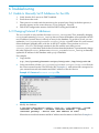
5.15 Creating a Baseline Report of the System Configuration
The sys_check utility is a data collection tool you can use to diagnose system errors and
problems. Use the sys_check utility now to create a baseline report of the system configuration
(software and hardware).
The sys_check utility collects configuration data only for the node on which it is run unless
you set and export the SYS_CHECK_SYSWIDE variable, which collects configuration data for all
nodes in the HP XC system.
Use the following commands to run the sys_check utility in its simplest form:
38
XC Software Installation
# export SYS_CHECK_SYSWIDE=1
# sys_check > /tmp/filename.html
By default, the sys_check utility creates the report in HTML format, but there is an option to
create a text version. You can redirect the output of the sys_check report to the directory and
file name of your choice.
For more information about this utility and its options, see the HP XC System Software
Administration Guide and sys_check(8).
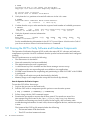
5.16 Setting Up VLAN
IMPORTANT: Set up the VLAN carefully and in accordance with the following procedures to
ensure that access to the switch management functions is available over the required network.
Setting up VLAN is particularly important if the system is on an external network because XC
uses an autodiscovery process.
VLANs are commonly used to split up groups of network users into manageable broadcast
domains, to create logical segmentation of workgroups, and to enforce security policies among
logical segments.
If a c3000-based configuration is connected to an external network, both the
Administrative/Console network and the external network are connected to the same switch.
Although IP addressing and subnetting can be used to separate these networks, the default
settings of the HP GbE2c Ethernet switch transmits broadcast traffic between the
Administrative/Console network and the external network.
To control the broadcast traffic and to allow separate management policies to be applied to the
Administrative/Console network from the external network, you can create a VLAN for the
Administrative/Console network. The VLAN must have, as its members, the internal ports of
the HP GbE2c switch that are connected to NIC1 of the servers (ports 1-8 on the switch) and the
switches management interface. By default, all ports are members of VLAN1.
To start up a hyperterminal, follow these steps:
1.
2.
3.
4.
5.
Go to Programs→Accessories→Communications→HyperTerminal.
Select COM1.
Fill in the following information:
Bits per second
9600
Data bits
8
Parity
None
Stop bits
1
Flow control
None
Click OK.
At the password prompt, type admin, which is the default.
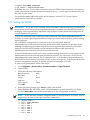
Enter the following HP GbE2c switch CLI commands to create a second VLAN. Name
VLAN#2 AdminNet and add the switch ports to it. The CLI prompts as follows:
NOTE: In the following example /cfg/l2/vlan 2, l2 is the letter l as in layer, not the
number one. Be sure to put a space between vlan and 2.
>>
>>
>>
>>
>>
>>
>>
>>
/cfg/l2/vlan 2
VLAN 2 name AdminNet
VLAN 2 add 1
VLAN 2 add 2
VLAN 2 add 3
VLAN 2 add 4
VLAN 2 add 5
VLAN 2 add 6
5.16 Setting Up VLAN
39
>>
>>
>>
>>
>>
6.
VLAN
VLAN
VLAN
VLAN
VLAN
2
2
2
2
2
add
add
add
add
ena
7
8
21
23
Assuming that the switch ssh or telnet management interface address has been assigned
to IP interface if 1, add that to the VLAN with the following commands:
>> VLAN 2 /cfg/l3/if 1
>> IP Interface 1 # vlan 2
7.
Enter / at the CLI prompt, apply, and save the configuration as follows:
>> apply
>> save
8.
Confirm saving to FLASH [y/n]: y
TIP: Attach the external ethernet to port 22 of the GbE2c switch to connect to the external
network.
For more information on how to configure VLANs for creating separate network segments,
including how to use VLAN tagging for devices that use multiple VLANs, see the HP GbE2c
Ethernet Blade Switch for c-Class BladeSystem Application Guide at:
http://bizsupport.austin.hp.com/bc/docs/support/SupportManual/c00701973/c00701973.pdf
For more information on how to configure VLANs for XC Software, see Section 2.6.4 in the HP
XC System Software Hardware Preparation Guide.
40
XC Software Installation
6 Troubleshooting
6.1 Unable to Manually Set IP Addresses for the iLOs
1.
2.
3.
4.
Verify that the iLOs are set to DHCP enabled.
Power down the node.
Then power it on and watch the monitor as the system boots. Early in the boot process, a
message appears on the screen that says "F8 to configure". Press F8.
Follow the configuration menu to find the DHCP setting and disable it.
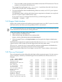
6.2 Changing External IP Addresses
The netinfo file is only read the first time cluster_config runs. Thus, manually changing
netinfo and rerunning cluster_config does not cause the database to be updated with the
new IP address, because there is already an entry in the database. To get this to work, you can
update the /etc/sysconfig/network-scripts/ifcfg-ethX file; where X is your external
network adapter (probably eth1) with the 16.118.48.57 address. Then perform a service
network restart. This change remains in the file until the next time you run
cluster_config, which then reads in the old values from the database. To permanently change
this value, either run reset_db then rerun cluster_prep and cluster_config, or manually
update the IP address in the database with mysql commands.
For example:
1.
Copy the file:
# cp /etc/sysconfig/network-scripts/ifcfg-eth1 /tmp/ifcfg-eth1.bk
2.
Using a text editor, edit the /etc/sysconfig/network-scripts/ifcfg-eth1 file with
the correct external entries. The file looks like Example 6-1, with entries that correspond to
your external network information and MAC address of the eth1 device.
Example 6-1 Contents of network-scripts File
3.
Modify the database:
# /opt/hptc/sbin/device_config --host n1 --type External --ipaddr
<external IP address> --netmask <external netmask> --gateway
<external gateway> --device eth1 <mac address of eth1>
Where the network information and MAC address are the same as in the file in Example 6-1.
6.1 Unable to Manually Set IP Addresses for the iLOs
41
Example 6-2 Modify Database
4.
(Optional) Edit the file /etc/sysconfig/netinfo to reflect the correct external network
information and MAC address.
Example 6-3 Sample netinfo File
5.
6.
Run the configuration scripts with the command service nconfig nconfigure.
Restart the network with the command service network restart.
6.3 Lost Connection to the iLO
If iLO2 is not responding to the browser, click Reset on the Diagnostic page of the iLO 2 browser
interface.
6.4 Removing a Bad Golden Image
To remove the golden image, follow these steps:
1.
2.
Login to the head node root user account.
Enter the following command:
# si_image base_image
3.
4.
5.
Go back to cluster_config and rerun it.
Rerun cluster_config and make sure it successfully runs to completion before attempting
to touch the keyboard or mouse again.
Enter the following command:
# sys_start image_and_reboot
42
Troubleshooting
6.5 Lost Terminal Window When in the IRC
If a terminal window fails to open in the IRC, press CTL ALT Backspace. This will take you
back to the login screen. After you login, you can open up a terminal window.
6.5 Lost Terminal Window When in the IRC
43
44
A Additional Software Setup Information
To change the iLO default user name and password
1.
2.
Under the hardware model, click iLO.
In the body of the main window, click the Web Administration link to open the Integrated
Lights-Out 2 utility in a new window. You might have to turn off popup blocking for this
window to open.
3. In the new window, click the Administration tab.
4. In the left frame, click the User Administration link.
5. Click the New button, and create a new iLO2 user name and password, which must match
the user name and password you set on the Onboard Administrator. Do not use any special
characters as part of the password.
Or, an alternate method is:
1. Access the MPI Main Menu.
2. Enter CM at the MP> prompt.
3. Enter UC at the MP:CM> prompt and follow the prompts to modify the user account.
To change the OA default user name and password
See Chapter 4 of the HP XC System Software: Hardware Preparation Guide Version 3.2.1 to change
the OA user name and password.
To change the Nagios default user name and password
The Nagios passwords are maintained in the /opt/hptc/nagios/etc/htpasswd.users
file. Use the htpasswd command to add, delete, or edit the user password.
SLURM post-configuration tasks
Perform this procedure as root user on the head node.
a. Go to Appendix J in the HP XC System Software Installation Guide to determine the type of
customizations that are available or required. For instance, if you installed and configured
SVA, SVA requires certain SLURM customizations.
b. Use the text editor of your choice to edit the SLURM configuration file: /hptc_cluster/
slurm/etc/slurm.conf
c. Use the information in Appendix J to customize the SLURM configuration according to your
requirements.
d. If you make changes to the slurm.conf file, save your changes and exit the text editor.
e. Update the SLURM daemons with this new information:
# scontrol reconfig
Use the SLURM post-configuration utility to update the slurm.conf file with the correct
processor count and memory size.
# spconfig
NOTE:
If a compute node did not boot up, the spconfig utility configures the node as follows:
Configured unknown node n14 with 1 CPU and 1 MB of total memory...
After the node has been booted up, rerun the spconfig utility to configure the correct settings.
For more information, see section 3.19.1 in the HP XC System Software Installation Guide.
45
46
B Additional Hardware Setup Information
B.1 HP Workgroup System Specifications
Table B-1 HP Workgroup System Specifications
Size1
Height 54.1 cm (21.20 in)
Width 34.24 cm (13.48 in)
Depth 87.45 cm (34.43 in)
Weight 2
87.09 kg (192 lb) to 155 kg (342 lb) depending on the
configuration
Power Requirements 1
C13/C14 power cords connected directly to low-line wall
outlets
Operating Temperature Range3
10°C to 35°C (50°F to 95°F)
Space and Air Flow 4
63.5 cm (25 in) front
76.2 cm (30 in) rear
121.9 cm (48 in) rear from the rear of another enclosure
or rack
1
2
3
4
For more details, see HP BladeSystem c3000 Enclosure – Specifications.
For more details, see HP BladeSystem c3000 QuickSpecs.
For more details, see All product manuals for HP BladeSystem c3000 Enclosures and click HP BladeSystem c3000
Enclosure and c3000 Tower Enclosure Maintenance and Service Guide.
For more details, see All product manuals for HP BladeSystem c3000 Enclosures and click HP BladeSystem c3000
Enclosure Setup and Installation Guide.
B.1.1 Thermal Stabilization
Before you remove the enclosure from its packaging, allow it enough time to adjust to the local
temperature and humidity of the new operating environment.
CAUTION: Failure to thermally stabilize cluster components can potentially damage drive
media or associated electronics when the cluster is activated.
Place the equipment in the room in which it is to be installed. If it arrives in a plastic bag, leave
it in the bag. If condensation is visible on any component, stabilize in the operating environment
for six hours or until the condensation is no longer visible, whichever is longer. Table B-2 specifies
the time required to thermally stabilize the enclosure, based on the ambient shipping temperature.
Table B-2 Thermal Stabilization Specification
Ambient Shipping Temperature Range Ambient Shipping Temperature Range Minimum Stabilization Time
(°C)
(°F)
60 to 66
140 to 151
3 hours
50 to 59
122 to 139
2 hours
40 to 49
104 to 121
1 hour
30 to 39
86 to 103
30 minutes
18 to 29
65 to 85
None
10 to 17
50 to 64
30 minutes
0 to 9
32 to 49
1 hour
-10 to -1
14 to 31
2 hours
-20 to -11
-4 to 13
3 hours
B.1 HP Workgroup System Specifications
47
Table B-2 Thermal Stabilization Specification (continued)
Ambient Shipping Temperature Range Ambient Shipping Temperature Range Minimum Stabilization Time
(°C)
(°F)
48
-30 to -21
-22 to -5
4 hours
-40 to -31
-40 to -21
5 hours
Additional Hardware Setup Information
C IP Addresses on a Corporate Network
Use this method if you have access to the corporate network and a DHCP server providing IP
addresses. In order to use this process, the iLOs must be set to DHCP enabled.
C.1 Cabling
1.
2.
Power off the enclosure.
Connect the RJ45 CAT5 patch cable from the OA1 interface port to port 24 of the GigE switch.
(Figure C-1) See Figure 1-3 (page 12) for the exact location of the interconnect switch. (Callout
2.)
Figure C-1 Interconnect Switch
The following list describes the callouts in Figure C-1:
1. Port 20 RJ-45 connector for 10/100/1000 Mb uplink
2. Port 21 RJ-45 connector for 10/100/1000 Mb uplink
3. Port 22 RJ-45 connector for 10/100/1000 Mb uplink
4. Port 23 RJ-45 connector for 10/100/1000 Mb uplink
5. Port 24 RJ-45 connector for 10/100/1000 Mb uplink
3.
Connect port 21 of the GigE switch to the corporate network.
C.2 IP Addresses
1.
2.
Extend the Insight Display Panel.
Power on the enclosure and wait for the display to show a network address other than
0.0.0.0. It changes to an address on the corporate network obtained from the DHCP server.
Figure C-2 Enclosure Settings Display
3.
4.
Connect your laptop to the corporate network and verify that you can ping the address
displayed by the OA.
Start a browser on your laptop and use the IP address listed in the OA1 IP address field to
launch the OA. Figure C-3 shows and example using Internet Explorer:
C.1 Cabling
49
Figure C-3 OA IP Address
On the warning page, click Continue to this website.
5.
50
Enter the Administrator user name and the password supplied with the HP Workgroup
System.
IP Addresses on a Corporate Network
D Configure sendmail
LSF requires a mail program to send job output to users who submit jobs and to send
administrative messages to the LSF administrator.
By default, LSF uses the sendmail mail program. The sendmail service is installed by default
on the head node in /usr/lib/sendmail, but you must configure sendmail to meet your
site requirements.
sendmail Configuration Requirements on an HP XC System
Although Linux sendmail typically functions correctly as shipped, current HP XC host naming
conventions cause sendmail to improperly identify itself to other mail servers. This improper
identification can lead to the mail being rejected by the remote server.
To remedy this issue, perform the following procedure on all nodes with an external connection
that will send mail:
1. Be sure you know the fully qualified host name associated with the node's external IP address.
2. On the head node, add an entry for the IP address and fully qualified host name to the top
of the /etc/hosts file. Make the entry above the comment #XC-CLUSTER Do Not Edit
Below this Line. An entry is similar to the following:
192.0.2.3
penguin.southpole.com
In the previous example, penguin.southpole.com is the fully qualified host name, and
192.0.2.3 is its external IP address.
3.
4.
Save the changes to the file and exit the text editor.
Use the text editor of your choice to open and edit the following file:
/etc/mail/submit.cf
5.
Locate the section of the file that is similar to this:
# my official domain name
# ... define this only if sendmail cannot automatically determine
# your domain
#Dj$w.Foo.COM
6.
Uncomment the macro and include the fully qualified host name. The entry is similar to this
for penguin.southpole.com:
# my official domain name
# ... define this only if sendmail cannot automatically determine
# your domain
Djpenguin.southpole.com
7.
8.
Save the changes to the file and exit the text editor.
Use the text editor of your choice to open and edit the following file:
/etc/mail/sendmail.cf
9. Repeat steps 5 and 6 and make the same changes to the sendmail.cf file.
10. Save the changes to the file and exit the text editor.
11. Restart sendmail:
# service sendmail restart
To forward mail to users, the sendmail service requires users to create .forward files in their
home directories to specify where mail is to be sent.
If you intend to make additional, more advanced modifications to sendmail, HP recommends
that you do not modify the .cf files directly. Rather, modify the .mc files and run them through
an M4 processor to create the .cf files. The M4 processing tools are part of the sendmail-cf
RPM, which is not installed by default. The sendmail-cf RPM is available on the HP XC
distribution DVD in the extra RPMs directory.
51
Consult any third-party Linux system administration reference manual if you need more
information about configuring sendmail.
To use a mail program other than sendmail, set the LSB_MAILPROG variable in the /opt/
hptc/lsf/top/conf/lsf.conf file to the appropriate mail program after the system
configuration is complete.
52
Configure sendmail
Glossary
A
administration
network
The private network within the HP XC system that is used for administrative operations.
B
base image
The collection of files and directories that represents the common files and configuration data
that are applied to all nodes in an HP XC system.
branch switch
A component of the administration network. A switch that is uplinked to the root switch and
receives physical connections from multiple nodes.
C
cluster
A set of independent computers combined into a unified system through system software and
networking technologies.
compute node
A node that is assigned only with the compute role and no other. Jobs are distributed to and
run on nodes with the compute role; no other services run on a compute node.
.
D
DHCP
Dynamic Host Control Protocol. A protocol that dynamically allocates IP addresses to computers
on a local area network.
Dynamic Host
Control Protocol
See DHCP.
E
enclosure
The hardware and software infrastructure that houses HP BladeSystem servers.
G
golden image
A collection of files, created from the golden client file system that are distributed to one or
more client systems. Specific files on the golden client may be excluded from the golden image
if they are not appropriate for replication.
H
head node
The single node that is the basis for software installation, system configuration, and
administrative functions in an HP XC system. There may be another node that can provide a
failover function for the head node, but HP XC system has only one head node at any one time.
host name
The name given to a computer. Lowercase and uppercase letters (a–z and A–Z), numbers (0–9),
periods, and dashes are permitted in host names. Valid host names contain from 2 to 63
characters, with the first character being a letter.
I
I/O node
A node that has more storage available than the majority of server nodes in an HP XC system.
This storage is frequently externally connected storage, for example, SAN attached storage.
When configured properly, an I/O server node makes the additional storage available as global
storage within the HP XC system.
iLO
Integrated Lights Out. A self-contained hardware technology available on CP3000 and CP4000
cluster platform hardware models that enables remote management of any node within a
system.
53
iLO2
The next generation of iLO that provides full remote graphics console access and remote virtual
media.
See also iLO.
image server
A node specifically designated to hold images that will be distributed to one or more client
systems. In a standard HP XC installation, the head node acts as the image server and golden
client.
Integrated Lights
Out
See iLO.
interconnect
A hardware component that provides high-speed connectivity between the nodes in the HP
XC system. It is used for message passing and remote memory access capabilities for parallel
applications.
interconnect
module
A module in an HP BladeSystem server. The interconnect module provides the Physical I/O
ports for the server blades and can be either a switch, with connections to each of the server
blades and some number of external ports, it can be or a pass-through module, with individual
external ports for each of the server blades.
See also server blade.
interconnect
network
The private network within the HP XC system that is used primarily for user file access and
for communications within applications.
Internet address
A unique 32-bit number that identifies a host's connection to an Internet network. An Internet
address is commonly represented as a network number and a host number and takes a form
similar to the following: 192.0.2.0.
ITRC
HP IT Resource Center. The HP corporate web page where software patches are made available.
The web address is http://www.itrc.hp.com. To download patches from this web page, you
must register as an Americas/Asia Pacific or European customer.
L
load file
A file containing the names of multiple executables that are to be launched simultaneously by
a single command.
Load Sharing
Facility
See LSF-HPC with SLURM.
local storage
Storage that is available or accessible from one node in the HP XC system.
LSF execution
host
The node on which LSF runs. A user's job is submitted to the LSF execution host. Jobs are
launched from the LSF execution host and are executed on one or more compute nodes.
LSF master host
The overall LSF coordinator for the system. The master load information manager (LIM) and
master batch daemon (mbatchd) run on the LSF master host. Each system has one master host
to do all job scheduling and dispatch. If the master host goes down, another LSF server in the
system becomes the master host.
LSF-HPC with
SLURM
Load Sharing Facility for High Performance Computing integrated with SLURM. The batch
system resource manager on an HP XC system that is integrated with SLURM. LSF-HPC with
SLURM places a job in a queue and allows it to run when the necessary resources become
available. LSF-HPC with SLURM manages just one resource: the total number of processors
designated for batch processing.
LSF-HPC with SLURM can also run interactive batch jobs and interactive jobs. An LSF interactive
batch job allows you to interact with the application while still taking advantage of LSF-HPC
with SLURM scheduling policies and features. An LSF-HPC with SLURM interactive job is run
without using LSF-HPC with SLURM batch processing features but is dispatched immediately
by LSF-HPC with SLURM on the LSF execution host.
See also LSF execution host.
M
MCS
54
An optional integrated system that uses chilled water technology to triple the standard cooling
capacity of a single rack. This system helps take the heat out of high-density deployments of
servers and blades, enabling greater densities in data centers.
Glossary
MySQL
A relational database system developed by MySQL AB that is used in HP XC systems to store
and track system configuration information.
N
NAT
Network Address Translation. A mechanism that provides a mapping (or transformation) of
addresses from one network to another. This enables external access of a machine on one LAN
that has the same IP address as a machine on another LAN, by mapping the LAN address of
the two machines to different external IP addresses.
Network Address
Translation
See NAT.
Network
Information
Services
See NIS.
NIS
Network Information Services. A mechanism that enables centralization of common data that
is pertinent across multiple machines in a network. The data is collected in a domain, within
which it is accessible and relevant. The most common use of NIS is to maintain user account
information across a set of networked hosts.
NIS client
Any system that queries NIS servers for NIS database information. Clients do not store and
maintain copies of the NIS maps locally for their domain.
NIS master server
A system that stores the master copy of the NIS database files, or maps, for the domain in the
/var/yp/DOMAIN directory and propagates them at regular intervals to the slave servers. Only
the master maps can be modified. Each domain can have only one master server.
NIS slave server
A system that obtains and stores copies of the master server's NIS maps. These maps are updated
periodically over the network. If the master server is unavailable, the slave servers continue to
make the NIS maps available to client systems. Each domain can have multiple slave servers
distributed throughout the network.
O
OA
The enclosure management hardware, software, and firmware that is used to support all of the
managed devices contained within the HP BladeSystem c-Class enclosure.
onboard
administrator
See OA.
P
parallel
application
An application that uses a distributed programming model and can run on multiple processors.
An HP XC MPI application is a parallel application. That is, all interprocessor communication
within an HP XC parallel application is performed through calls to the MPI message passing
library.
PXE
Preboot Execution Environment. A standard client/server interface that enables networked
computers that are not yet installed with an operating system to be configured and booted
remotely. PXE booting is configured at the BIOS level.
R
resource
management role
Nodes with this role manage the allocation of resources to user applications.
role
A set of services that are assigned to a node.
Root
Administration
Switch
A component of the administration network. The top switch in the administration network; it
may be a logical network switch comprised of multiple hardware switches. The Root Console
Switch is connected to the Root Administration Switch.
root node
A node within an HP XC system that is connected directly to the Root Administration Switch.
55
S
server blade
One of the modules of an HP BladeSystem. The server blade is the compute module consisting
of the CPU, memory, I/O modules and other supporting hardware. Server blades do not contain
their own physical I/O ports, power supplies, or cooling.
SLURM backup
controller
The node on which the optional backup slurmctld daemon runs. On SLURM failover, this
node becomes the SLURM master controller.
SLURM master
controller
The node on which the slurmctld daemon runs.
SMP
Symmetric multiprocessing. A system with two or more CPUs that share equal (symmetric)
access to all of the facilities of a computer system, such as the memory and I/O subsystems. In
an HP XC system, the use of SMP technology increases the number of CPUs (amount of
computational power) available per unit of space.
ssh
Secure Shell. A shell program for logging in to and executing commands on a remote computer.
It can provide secure encrypted communications between two untrusted hosts over an insecure
network.
symmetric
multiprocessing
See SMP.
56
Glossary
Index
A
administrative network
configuring VLAN for, 39
testing, 36
B
backup
CMDB, 38
bad golden image, 42
boot order, 19
C
cluster_config, 31
cluster_prep, 28
CMDB
backing up, 38
documentation, 38
compute node
testing, 36
configuration and management database (see CMDB)
configuration data
creating baseline report, 38
configuring
VLANs, 39
CPU usage
testing, 36
XC.lic file, 30
log file
OVP, 36
lost terminal window, 43
LSF
sendmail, 51
testing, 36
LSF-HPC with SLURM
verifying operation, 35
M
managedb command, 38
memory usage
testing, 36
N
Nagios
verifying system health, 37
network connectivity
testing, 36
nrg command, 37
O
operation verification program (see OVP)
OVP, 36
invoking, 36
log file, 36
D
S
database backup, 38
discover command, 30
documentation
hardware, 13
documentation updates, 10
sendmail setup, 51
SLURM
testing, 36
smart array, 20
SNMP trap, 34
software
documentation, 23
preinstallation checklist, 23
prerequisites, 23
startsys, 34
sys_check utility, 38
system monitoring
Nagios, 37
nrg command, 37
system overview, 11
system verification, 36
F
firmware, 13
H
hardware
installing, 17
preinstallation checklist, 13
prerequisites, 13
setup, 15
I
ilo, 19
installation
verifying, 36
installing patches, 29
ip addresses, 17, 41
on corporate network, 49
L
license
location of license key file, 30
T
telnet, 20
thermal stabalization, 47
troubleshooting
using the nrg command, 37
V
VLANs
configuring, 39
57
X
XC installation, 27
XC license, 24
XC patches, 24
58
Index
59