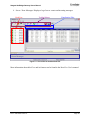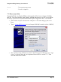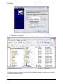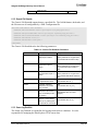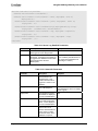
1
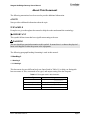
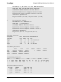
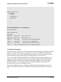
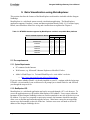
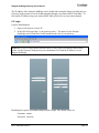
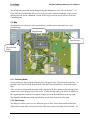
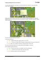
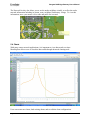
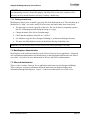
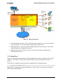
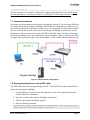
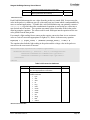
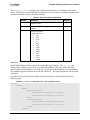
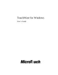
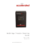
Stargate NetBridge Gateway User’s Manual
Revision A, October 2007
PN: 7430-0449-01
© 2007 Crossbow Technology, Inc. All rights reserved.
Information in this document is subject to change without notice.
Crossbow, IRIS, MICA, TrueMesh and XMesh are registered trademarks of Crossbow
Technology, Inc. Other product and trade names are trademarks or registered trademarks of their
respective holders.
Stargate NetBridge Gateway User’s Manual
Table of Contents
1
2
Introduction.............................................................................................................................1
1.1
Stargate NetBridge Gateway Overview......................................................................... 1
1.2
Package Contents........................................................................................................... 1
Quick Start WSN Kit Users ...................................................................................................2
2.1
3
Hardware Overview ...............................................................................................................7
3.1
4
5
6
7
8
Stargate NetBridge Gateway.......................................................................................... 7
System Configuration.............................................................................................................9
4.1
Boot Procedure .............................................................................................................. 9
4.2
Gateway Server Statistics .............................................................................................. 9
4.3
Network Topologies .................................................................................................... 11
Data Visualization using MoteExplorer .............................................................................12
5.1
Pre-requirements.......................................................................................................... 12
5.2
Login............................................................................................................................ 13
5.3
Map .............................................................................................................................. 14
5.4
Charts ........................................................................................................................... 16
5.5
Network ....................................................................................................................... 22
5.6
Data.............................................................................................................................. 26
Data logging and Visualization using MoteView ...............................................................27
6.1
Remote Connection using MoteView.......................................................................... 27
6.2
MoteView at a Glance .................................................................................................. 28
Advanced Stargate NetBridge Administration ..................................................................30
7.1
Remote Stargate NetBridge Administration ................................................................ 30
7.2
MoteExplorer Administration...................................................................................... 33
7.3
XServe Administration ................................................................................................ 33
7.4
Recovery of the XServe ............................................................................................... 37
7.5
Direct connection to a PC using Crossover cable ........................................................ 38
7.6
Assigning Static IP address.......................................................................................... 40
7.7
Commercial networks .................................................................................................. 41
7.8
Re-programming the base using UISP utility .............................................................. 41
Appendix A. Advanced XServe Configuration ..................................................................42
8.1
9
Out-of-the-Box Demo.................................................................................................... 2
Configuring XServe..................................................................................................... 42
Appendix B. Accessories ......................................................................................................51
9.1
Crossbow Accessories: ................................................................................................ 51
Doc. # 7430-0449-01 Rev. A
Page i
Stargate NetBridge Gateway User’s Manual
9.2
10
Other Accessories ........................................................................................................ 51
Appendix C. Warranty and Support Information..........................................................52
10.1
Customer Service ..................................................................................................... 52
10.2
Contact Directory ..................................................................................................... 52
10.3
Return Procedure...................................................................................................... 52
10.4
Warranty................................................................................................................... 53
Page ii
Doc. # 7430-0449-01 Rev. A
Stargate NetBridge Gateway User’s Manual
About This Document
The following annotations have been used to provide additional information.
; NOTE
Note provides additional information about the topic.
; EXAMPLE
Examples are given throughout the manual to help the reader understand the terminology.
3 IMPORTANT
This symbol defines items that have significant meaning to the user
WARNING
The user should pay particular attention to this symbol. It means there is a chance that physical
harm could happen to either the person or the equipment.
The following paragraph heading formatting is used in this manual:
1 Heading 1
1.1 Heading 2
1.1.1 Heading 3
This document also uses different body text fonts (listed in Table 0-1) to help you distinguish
between names of files, commands to be typed, and output coming from the computer.
Table 0-1. Font types used in this document.
Font Type
Usage
Courier New Normal
Sample code and screen output
Courier New Bold
Commands to be typed by the user
Times New Roman Italic TinyOS files names, directory names
Franklin Medium Condensed
Doc. # 7430-0449-01 Rev. A
Text labels in GUIs
Page iii
Stargate NetBridge Gateway User’s Manual
1 Introduction
This User’s Manual describes the features and operation of the Stargate NetBridge embedded
wireless sensor network gateway.
1.1 Stargate NetBridge Gateway Overview
Stargate NetBridge is a Linux based embedded Wireless Sensor Network (WSN) gateway based
on the Linksys NSLU2 device. It has been modified by Crossbow to specifically support the
functionality of a WSN gateway. For any questions or assistance with this product please contact
Crossbow technical support; do not contact Linksys directly as they will not be able to assist with
issue regarding this particular device.
1.2 Package Contents
The Stargate NetBridge Gateway package includes:
•
1 x Stargate NetBridge
•
1 x USB FLASH disk
•
1 x Stargate NetBridge power supply
•
1 x Stargate NetBridge vertical stand
•
1 x Ethernet cable
•
1 x CD with the software and documentation
Doc. # 7430-0449-01 Rev. A
Page 1
Stargate NetBridge Gateway User’s Manual
2 Quick Start WSN Kit Users
2.1 Out-of-the-Box Demo
This section will step you through the process of setting up a simple Mote sensor network
demonstration. The four main steps are to
1. Set-up Stargate NetBridge
2. Set up BU base station and SN sensor nodes (optional)
3. Run the GatewayConfig tool to find the IP address of the Stargate NetBridge
4. Start MoteExplorer and visualize sensor data from the wireless sensor network
2.1.1 Setting-up Stargate NetBridge
To get started and set-up the Stargate NetBridge
•
Remove the Stargate NetBridge gateway from its packaging. An included base can be
used for upright operation.
•
The bag holding the Stargate NetBridge also contains an USB FLASH disk included in
the package. Insert this device into the bottom USB port of the Stargate NetBridge
labeled “Disk 1”. Please make sure that the side with the electrical contacts on the USB
disk mates with the contacts inside the USB connector. If the USB disk is plugged in the
wrong way the Stargate NetBridge will not boot.
•
Also included are a CAT5 Ethernet cable and a snap-on inductor. For optimal noise
reduction, place the inductor close to the connector that will plug into the Stargate
NetBridge and snap it in place.
•
Connect the Ethernet cable to the Stargate NetBridge Ethernet port. The other end would
typically plug into a Router or Ethernet hub/switch. If a direct connection to a PC without
a Router is desired, a special cross-over cable (not included) must be used. Refer to
Section 7.4 for further details on this type of setup.
Figure 2-1. Typical network configuration
Page 2
Doc. # 7430-0449-01 Rev. A
Stargate NetBridge Gateway User’s Manual
•
Insert the included power adapter into a standard electrical outlet and plug the power
connector into the Stargate NetBridge. Upon application of external power, the Stargate
NetBridge will commence its boot procedure, it is not necessary to push the power button
at the front of the device.
2.1.2 Setting up the BU base station and SN sensor nodes (Optional)
•
If you purchased a Sensor Network base station such as the BU900, BU2110, or BU2400
with the Stargate NetBridge plug its USB cable into the remaining USB slot on the
Stargate NetBridge labeled “Disk 2”. If you are planning to add other USB devices to the
Stargate NetBridge, the “Disk 2” port can be attached to a standard USB hub which in
turn can host additional devices. Make sure that the external USB hub is powered (active)
if the attached devices exceed the power capabilities of a passive hub. Never attach the
system FLASH disk via a hub, always plug it in directly into the “Disk 1” port.
•
If you purchased the packaged SN series Sensor Nodes, they should be labeled with
Unique Node ID.
•
Insert batteries into the battery holder compartment of the Sensor Nodes and turn the
power switch to the ON position.
•
Spread the nodes around on your desk top or in the office area. Make sure that the sensor
nodes are resting on their bases with antenna pointing vertically upwards.
2.1.3 Run the GatewayConfig tool to find the IP address of the Stargate NetBridge
In order to connect to the Stargate NetBridge its hostname or IP address has to be known. The
GatewayConfig tool can help scan and find the IP address. Some networks will resolve the
hostname properly so knowing the NetBridge’s IP address is not required.
•
The hostname is determined by the prefix sluggo- and the 5-digit serial number that can
be found on the sticker attached to the bottom of the device (e.g., SN = 00006 ->
hostname is sluggo-00006).
•
Enter http://hostname (e.g., http://sluggo-00006) into your Web browser. If the
MoteExplorer welcome screen appears you do not need to install the GatewayConfig
tool, skip to the next section.
•
Install GatewayConfig by double-clicking on GatewayConfigSetup_<version>.exe file
found on the CD.
•
The Setup wizard would guide you through the installation process. Make sure to check
all the installation options (you would need Microsoft .NET Framework 2.0)
Doc. # 7430-0449-01 Rev. A
Page 3
Stargate NetBridge Gateway User’s Manual
•
Run GatewayConfig from Windows Start>Programs>Crossbow>GatewayConfig.
•
In the GatewayConfig GUI, click on Scan.
•
Allow sometime for the scanning to complete and the GUI would display a list the
Stargate NetBridge gateways that were found in your network.
•
Make a note of the IP address assigned to your hostname. Double-clicking on this IP
address will open the MoteExplorer in a web browser.
Page 4
Doc. # 7430-0449-01 Rev. A
Stargate NetBridge Gateway User’s Manual
2.1.4 Start-up MoteExplorer
The primary interface to the Stargate NetBridge can be accessed using a Web browser on a
locally connected PC. In order to connect to the Stargate NetBridge its hostname or IP address
has to be known.
•
Open a web browser (eg. Internet Explorer or Firefox)
•
The following URLs will bring up the MoteExplorer login screen: http://hostname or
http://ip-address
•
MoteExplorer requires a username and password to login. Type the default values below
and click on Login.
Username: admin
Password: crossbow
; NOTE: If you do not have Adobe’s Flash 9.x installed in your browser, you will be
prompted by your browser to install it. Follow the instructions given by your browser and then
retry the above steps.
You should see nodes appear in the node list on the left hand side of the MoteExplorer window.
MoteExplorer has four main user interface sections which you can browse and use.
•
Map: Shows a Mote network map with placement and parenting information.
Doc. # 7430-0449-01 Rev. A
Page 5
Stargate NetBridge Gateway User’s Manual
•
Chart: Provides the ability to generate graphs of a sensor data vs. time for a set of nodes.
•
Network: Displays the latest health packet readings received for each node in the
network
•
Data: Displays the latest sensor readings received for each node in the network.
Figure 2-2. Screenshot of the MoteExplorer GUI
More information about MoteExplorer and its features can be found in the Chapter 5 of the
manual.
; NOTE: To turn off the power, press the power button. This allows Stargate NetBridge to
correctly shutdown the operating system and takes about 40 seconds.
Page 6
Doc. # 7430-0449-01 Rev. A
Stargate NetBridge Gateway User’s Manual
3 Hardware Overview
3.1 Stargate NetBridge Gateway
The Stargate NetBridge gateway is an embedded Sensor Network gateway device. It is based on
the Intel IXP420 XScale processor running at 266MHz. It features one wired Ethernet and two
USB 2.0 ports. The device is further equipped with 8MB of program FLASH, 32MB of RAM
and a 2GB USB 2.0 system disk.
The Stargate NetBridge runs the Debian Linux operating system. It comes preloaded with
Crossbow’s Sensor Network management and data visualization software packages,
MoteExplorer and XServe. Those programs are automatically started when a Sensor Network
base station is plugged into the secondary USB port.
Figure 3-1. Photo of the Stargate NetBridge
Doc. # 7430-0449-01 Rev. A
Page 7
Stargate NetBridge Gateway User’s Manual
3.1.1 Performance Specifications
Table 3-1. Stargate NetBridge Gateway Performance Specifications
Parameter
Operating Value
CPU
IXP420 @ 266MHz
Program Flash
8 MB
RAM
32 MB
USB Flash Disk
2 GB
3.1.2 Electrical Specifications
The electrical specifications for the Stargate NetBridge Gateway are provided in Table 3-2.
Table 3-2. Stargate NetBridge Gateway Electrical Specifications
Parameter
Operating Value
Voltage supply
5.0 Volts
Power Consumption
~3W
I/O
1 x RJ45 Ethernet (IEEE 802.3, 802.3u)
2 x USB 2.0 host (USB 1.0/1.1 compatible)
4 x status LEDs
1 x power LED
User Interfaces
1 x soft power button
1 x Reset button
1 x beeper
Automatic boot when powered
Other features
Real-time clock (battery backed-up RTC)
Watchdog timer
3.1.3 Environmental and Mechanical Specifications
The environmental and mechanical specifications for the Stargate NetBridge gateway are
provided in Table 3-3.
Table 3-3. Stargate NetBridge Gateway Environmental Specifications
Page 8
Parameter
Operating Value
Storage Temperature
-100 C to +600 C
Operating Temperature
50 C to + 400 C
Humidity
5% to 90 % non-condensing
Size
130 mm x 21 mm x 91 mm
Weight
160 g
Doc. # 7430-0449-01 Rev. A
Stargate NetBridge Gateway User’s Manual
4 System Configuration
4.1 Boot Procedure
The start of the boot process has the top LED named “Status” light up yellow. The LED just
below it labeled “Ethernet” will blink green at any time if a proper wired Ethernet connection is
present. After a short while, the Status LED will blink yellow and green alternately, followed by
all four LEDs blinking consecutively for a period of time. Subsequently, the bottom two LEDs
will turn off and the top LED will be yellow for a while. The boot process is complete when the
“Disk 1” LED starts lighting up and the Status LED turns blinks green and yellow. A short beep
indicates the completion of the boot procedure as well. The whole process takes about two
minutes.
After Stargate NetBridge has powered up, you should see the front indicators showing the
following status.
Table 4-1. Stargate NetBridge Gateway LED indicator
Indicator
Color
Power Button
Ready/Status
Status
Green
System on
Green/flashing Yellow
System running
Yellow then flashing Green
System boot
Ethernet
Flashing Green
Network activity
Disk2
Solid Green
XServe Running
Disk1
Green
USB disk running
; NOTE: To turn off the power, press the power button. This allows Stargate NetBridge to
correctly shutdown the operating system and takes about 40 seconds.
4.2 Gateway Server Statistics
The gateway server statistics page provide information about the network interfaces, disk
allocation, memory usage, process list along with memory allocations. This can be accessed by
typing the following URL in a web browser.
http://<hostname>/server.html or http://<ip-address>/server.html
This is useful in finding if the gateway is running out of disk space or memory.
Server Information
Hostname: sluggo-00006
Server Uptime:
14:20:02 up 20:53,
0 users,
load average: 0.07, 0.08, 0.07
Current Date: Tue Sep 25 14:20:02 PDT 2007
Network Interfaces:
eth0
Link encap:Ethernet
Doc. # 7430-0449-01 Rev. A
HWaddr 00:14:BF:68:8C:A1
Page 9
Stargate NetBridge Gateway User’s Manual
inet addr:10.1.1.248
Bcast:10.1.1.255
Mask:255.255.255.0
inet6 addr: fe80::214:bfff:fe68:8ca1/64 Scope:Link
UP BROADCAST RUNNING MULTICAST
MTU:1500
Metric:1
RX packets:459986 errors:0 dropped:0 overruns:0 frame:0
TX packets:2527 errors:0 dropped:0 overruns:0 carrier:0
collisions:0 txqueuelen:100
RX bytes:32502391 (30.9 MiB)
lo
TX bytes:1142335 (1.0 MiB)
Link encap:Local Loopback
inet addr:127.0.0.1
Mask:255.0.0.0
inet6 addr: ::1/128 Scope:Host
UP LOOPBACK RUNNING
MTU:16436
Metric:1
RX packets:8 errors:0 dropped:0 overruns:0 frame:0
TX packets:8 errors:0 dropped:0 overruns:0 carrier:0
collisions:0 txqueuelen:0
RX bytes:560 (560.0 b)
TX bytes:560 (560.0 b)
Total Disk Allocation:
Filesystem
Size
Used
Avail Use% Mounted on
/dev/sda1
2.0G
446M
1.5G
tmpfs
16M
0
16M
0% /lib/init/rw
udev
11M
33k
11M
1% /dev
tmpfs
16M
0
16M
0% /dev/shm
24% /
Total Memory Allocation:
total
used
free
shared
buffers
cached
Mem:
30707712
29478912
1228800
0
5242880
6508544
Swap:
132849664
4775936
128073728
Total:
163557376
34254848
129302528
Virtual Memory Statistics:
procs -----------memory---------- ---swap-- -----io---- -system-- ----cpu---r
b
swpd
free
buff
cache
si
so
bi
bo
in
1
0
4664
1192
5120
6356
0
0
1
11
175
cs us sy id wa
21
1
1 96
2
Per-process Memory Allocation:
PID USER
COMMAND
START %MEM %CPU
1 root
init
Sep24
1.9
0.0
2 root
ksoftirqd/0
Sep24
0.0
0.0
3 root
events/0
Sep24
0.0
0.0
……..
Page 10
Doc. # 7430-0449-01 Rev. A
Stargate NetBridge Gateway User’s Manual
……..
……..
Current Process List:
PID COMMAND
1 init [2]
2 [ksoftirqd/0]
3 [events/0]
……..
……..
……..
XServe/MoteExplorer Information
XServe Processes:
XServe System Files:
total 8236
drwxr-xr-x
2 user user
drwxrwxr-x 14 user user
4096 Sep 25 14:19 .
4096 Aug 31 15:12 ..
-rwxr--r--
1 user user
32 Aug 31 13:56 basejoinmap.xtbl
-rwxr--r--
1 user user
12 Aug 31 13:56 joinmap.xtbl
-rwxr--r--
1 user user
28 Aug 31 13:56 joinreject.xtbl
-rwxr--r--
1 user user 8399872 Sep 25 14:19 xserve_sqlite.db
4.3 Network Topologies
For this user guide we will assume that the network to which the Stargate NetBridge is connected
consists of a class C IP network (e.g., of the type 192.168.x.x). It is further assumed that this
network consists of a NAT router with DHCP server capability, a WAN port connected to the
Internet and LAN ports hosting the Stargate NetBridge and at least one local PC.
There are a number of different possible network configurations the Stargate NetBridge can be
connected to. Further examples are briefly discussed in the Appendix. Note that the Stargate
NetBridge should never be directly connected to the Internet without using a NAT router or
firewall. This poses a serious security risk as the Stargate NetBridge is not equipped with
firewall protection to prevent unauthorized access.
The Stargate NetBridge is factory configured for DHCP (dynamic IP address). If a static IP
address is desired it will need to be reconfigured using the procedure described in the Section
7.6.
Doc. # 7430-0449-01 Rev. A
Page 11
Stargate NetBridge Gateway User’s Manual
5 Data Visualization using MoteExplorer
This section describes the features of the MoteExplorer web interface included with the Stargate
NetBridge.
MoteExplorer is a web-based sensor network visualization application. The MoteExplorer
application supports Crossbow’s sensor and data acquisition boards (Table 1-1). For other legacy
boards, users should use MoteView to log and visualize data as explained in Chapter 6.
Table 5-1. MTS/MDA boards supported by MoteExplorer and their compatible Mote platforms
Mote Platforms
Sensor and Data Acquisition Boards
IRIS
MICAz
MICA2
3
3
3
MTS300/310
3
3
3
MTS400
3
3
3
MTS420
3
3
3
MTS300/310
MDA100
3
3
3
MDA300
3
3
3
MDA320
3
3
3
5.1 Pre-requirements
5.1.1 System Requirements
•
PC connected to the Internet.
•
Web browser, e.g. Microsoft’s Internet Explorer or Mozilla’s Firefox
•
Adobe’s Flash Player 9.x. To install Flash Player 9.x visit Adobe’s web site:
o
http://www.macromedia.com/software/flash/about/
If you are unsure whether Flash 9.x is already installed on your PC, continue with the login steps.
If Flash 9.x is not installed, your web browser will prompt you to install Flash 9.x and will lead
you through the steps to do so.
5.1.2 MoteExplorer URL
MoteExplorer is a web-based application and can be accessed through a PC’s web browser. To
access the application users will need the MoteExplorer URL address. Users can use either the
hostname of their Stargate NetBridge written on a sticker attached to one side of the device or an
IP Address. For users on a corporate or university network, the hostname should be enough to
allow users to find the application through the browser. Most home routers do not support the
means to use the hostname on the side of the box. In those cases users will need to use the IP
address of the Stargate NetBridge device.
Page 12
Doc. # 7430-0449-01 Rev. A
Stargate NetBridge Gateway User’s Manual
The IP address of the Stargate NetBridge can be found either using the GatewayConfig tool (see
GatewayConfig section) or can be found manually through your routers DHCP client table. To
look up the IP address using your routers DHCP table, please refer to your routers manual.
5.2 Login
Login to MoteExplorer:
1. Open a web browser on your PC.
2. In the URL field type http://<your gateway name>. The name of your Stargate
NetBridge can be found on a sticker attached to the side of your gateway.
; NOTE: If you’re using a home network router or can’t login with using the name on the
sticker, use the GatewayConfig tool on your installation CD to find the IP address of your
Stargate NetBridge.
MoteExplorer requires a username and password to login. The default values are:
Username: admin
Password: crossbow
Doc. # 7430-0449-01 Rev. A
Page 13
Stargate NetBridge Gateway User’s Manual
The default user password can be changed using the ManageUser tool (refer to Section 7.3.4 )
Users who have modified the XServe Server process on the Stargate NetBridge to run on nondefault ports can use the “Advanced” section of the Login screen to specify the new Data and
Command ports.
5.3 Map
MoteExplorer provides users will a mechanism to visualize sensor data relative to a user
provided map.
Magnification
Data Overlays
Un-positioned
Nodes
5.3.1 Positioning Nodes
As new nodes are detected in the Network they will appear in the Un-positioned Nodes box. To
position a node onto the Map, drag the node from the Un-positioned box to its location on the
Map.
Once you have positioned all the nodes on the map, press the Save button on the top right of the
screen to save your changes back to the server. If after moving nodes, you decide to rollback to
the original positions instead of saving the changes, press the Reload button on the top right.
The Magnification Buttons on the top left allow you to zoom in and out of the map.
5.3.2 Data Overlays
The Map view allows you to see two different types of data: Sensor Data and Network Data.
When on the sensor data overlay users will see the most recent sensor data from each node. To
Page 14
Doc. # 7430-0449-01 Rev. A
Stargate NetBridge Gateway User’s Manual
view the sensor data place your mouse over the node and wait a second. A pop-up with the
sensor data will appear.
When on the network data overlay users will see Network routing information for each node.
Initially users will see node parent and route information visually. Each link represents a parent
child relationship.
The color of the link indicates its quality.
Link Quality Indicators:
•
Green – Both incoming and outgoing links are over 90%
•
Orange – Either one or both of the incoming or outgoing links is between 90% and 40%
•
Red – Either one or both the incoming or outgoing links is below 40%
The color of the nodes indicates how man potential good neighbors a node has.
Node Neighbor Quality Indicators:
•
Green – Node has more than two neighbors with Green link quality
•
Orange – Node has only one node with Green link quality
•
Red – Link has no nodes with Green link quality
Doc. # 7430-0449-01 Rev. A
Page 15
Stargate NetBridge Gateway User’s Manual
The Network Overlay also allows you to see the nodes neighbors visually as well as the nodes
network information including its parent, route, neighbors, and battery voltage. To view this
information, move your mouse over a node and pause for a second.
5.4 Charts
With many sensor network applications, it is important to view data trends over time.
MoteExplorer allows users to visualize data trends through advanced charting tools.
Users can create new charts, load existing charts, and save/delete chart configurations.
Page 16
Doc. # 7430-0449-01 Rev. A
Stargate NetBridge Gateway User’s Manual
5.4.1 Creating new charts
When selecting the “New…” chart drop down, the user is shown a charting wizard to help them
create a new chart. Users can select:
•
Chart Name: This is the name that is displayed on chart tab.
•
Axis-1 Sensor Chooser: This is the sensor that is plotted on the first y-axis
•
Axis-2 Sensor Chooser: This is the sensor that is plotted on the second y-axis. This axis
is optional.
•
Node Chooser: Sensor values will be charted for the selected nodes.
•
Date Range: Data for the given date range will be displayed. Users can choose from preselected ranges such as Last Hour, Last Day and Last Week or can use the Custom date
range to select a custom start and end date.
•
Plot Type: Users can select to see data as a line chart, point chart, or hi-low chart.
Doc. # 7430-0449-01 Rev. A
Page 17
Stargate NetBridge Gateway User’s Manual
After completing the wizard MoteExplorer will retrieve the specified data and chart it. To view
a specific value and time on the chart, place the mouse over the point and a pop up with the exact
value and time will appear.
Large Datasets
MoteExplorer attempts to display large datasets which can be accumulated over long time ranges
in a meaningful manner to the user. To do this, MoteExplorer uses aggregated data for charts
that span long time ranges. The aggregate data is displayed as an average over a time range with
a minimum and maximum value. Users can view the detailed data of an aggregate by specifying
a shorter date range which encompasses that data point.
•
Charting date ranges less than a single day display detailed data for every point.
•
Charting date ranges between a single day and a week are displayed as hourly aggregates
of the data.
•
Charting date ranges between a week and 6 months are displayed as daily aggregates of
the data.
•
Charting date ranges between 6 months and 2 years are displayed as 10-day aggregates of
the data.
•
Charting date ranges over 2 years are displayed as 30-day aggregates of the data.
Plot Type
When displaying data, the user can choose one of three plot types: Line, Point, or High Low. Line
plots connect a line between the individual data points, attempting to interpolate the trend being
displayed. Point plots display each data value as a point with not connections. Finally HighLow plots display each data value as a bar ranging between its maximum and minimum value.
The data values plotted for a particular chart depends on the whether a detailed or aggregate data
point is displayed. When displaying detailed data the Line and Point plots display the actual data
value. Since detailed data does not have a maximum and minimum value (like aggregate data),
the High-Low plot displays as a Point plot for detailed data values.
When displaying aggregate data the Line and Point plots display the average value of the
aggregate point over that time. The minimum and maximum value for the aggregate is displayed
when the mouse is held over a point. The High-Low plot displays a bar representing the
maximum and minimum value over that time range. The average value is displayed when the
mouse is held over the bar.
Page 18
Doc. # 7430-0449-01 Rev. A
Stargate NetBridge Gateway User’s Manual
5.4.2 Saving a chart
Once a chart is created a user can save a given chart to be reloaded later. When the user select
the “Save…” chart drop down a Save Chart wizard is displayed to the user. To save a chart the
user must select a unique name for the chart. This name will be used later to recall the given
chart so it is important that the user uses a descriptive name.
A summary of the charts parameters are displayed below the name. Note that pre-defined date
ranges such as Last Hour, Last Day and Last Week are relative date ranges. This means that
when the chart is loaded it will select data using the time of loading as the end time and will
select the start based on the relative date range.
This is not true for custom date ranges. When a custom date range is reloaded, the given start
and end date will always be used.
Doc. # 7430-0449-01 Rev. A
Page 19
Stargate NetBridge Gateway User’s Manual
5.4.3 Loading a chart
Once a chart is saved a user can load a given chart at a later date. When the user selects the
“Load…” chart drop down a Load Chart wizard is displayed to the user. The list of saved charts is
displayed in the drop down chooser. After selecting a saved chart name, the parameters of that
chart as summarized below the chart.
Note that pre-defined date ranges such as Last Hour, Last Day and Last Week are relative date
ranges. This means that when the chart is loaded it will select data using the time of loading as
the end time and will select the start time based on the relative date range.
This is not true for custom date ranges. When a custom date range is reloaded, the given start
and end date will always be used.
Page 20
Doc. # 7430-0449-01 Rev. A
Stargate NetBridge Gateway User’s Manual
5.4.4 Deleting a saved chart
Once a chart is saved a user can delete a given chart from MoteExplorer. When the user selects
the “Delete…” chart drop down a Delete Chart wizard is displayed to the user. The list of saved
charts is displayed in the drop down chooser. After selecting a saved chart name, the parameters
of that chart as summarized below the chart. Once a chart is deleted it no longer is available
using the load charting wizard.
The Delete Chart option is used to delete saved charts. Charts which were created with the
“New…” drop down and are not saved can be removed by clicking the X in the chart tab.
Doc. # 7430-0449-01 Rev. A
Page 21
Stargate NetBridge Gateway User’s Manual
5.4.5 Viewing chart data
Each chart is displayed as a named tab in the Charting window. Users can switch between charts
by clicking on the named tab for the chart to be displayed. Unused charts can be closed by
clicking on the X in the chart tab.
When viewing a detailed data set, users can choose to select the “Display Live Data” button. This
will continually update the chart with any new data that arrives from the network. This button is
only available on detailed data, and is not available when viewing aggregate data sets.
When viewing a chart, users can click the Refresh button on the left hand window to refresh the
chart with current data. When viewing a chart with a pre-defined Date Range this will readjust
the chart window with data from the end date of the date range starting from the current time.
5.5 Network
The Network window displays network diagnostic information, used to determine network
health. The Network window has three tabs:
•
Application Yield: This window gives hourly, daily and weekly yields for each type of
data packet coming from a node.
•
Mesh Health: This window displays per node health statistics such battery voltage and
number of hops. It also give neighbor information about a particular node.
•
Server Health: This window displays the gateway servers uptime and throughput.
Page 22
Doc. # 7430-0449-01 Rev. A
Stargate NetBridge Gateway User’s Manual
5.5.1 Application Yield
The Application Yield window displays hourly, daily and weekly display statistics for each type
of data packet arriving from a node. Yield is displayed as a percentage over the given time
range. In addition, the number of packets received by the server over the number of packets
generated by the node is also displayed in parenthesis next to each yield number.
In most Crossbow kits, the user will see two type of applications: Health and Sensor. Sensor
data is the data generated by the sensor application on the node. For example an MTS400
application will display MTS400 application values. Health data is generated by the mesh
software on the node and contains network diagnostic information.
Doc. # 7430-0449-01 Rev. A
Page 23
Stargate NetBridge Gateway User’s Manual
5.5.2 Mesh Health
The Mesh Health window displays per node health and neighbor statistics. The data displayed is
the following:
•
Battery Voltage: This is the current battery voltage of the node.
•
Hop Count: This is the number network hops this node is from the base station gateway.
•
Load: This indicates the amount of extra work this node is doing for other nodes in the
network. The value is the number of packets forwarded by this node over the number of
packets generated by this node. A load of 1 means that it is forwarding as many packets
at is generating. High load node could be considered bottle-necks in the network and can
run out of batteries quicker than other nodes in the network.
•
Packet Generated: This is the number of packet generated by this node.
•
Packets Forwarded: This is the number of packet forwarded by this node.
•
Last Updated: This is the last time this node has sent an update of its state.
In addition to these health statistics, the page also displays neighbor and route information in the
lower neighbor table. To display the neighbor and route information for a particular node click
on the row for that node in the node table.
The neighbor table displays the route the node takes back to the base station gateway above the
neighbor table. In addition for each neighbor to the node it displays the following:
Page 24
Doc. # 7430-0449-01 Rev. A
Stargate NetBridge Gateway User’s Manual
•
Path Cost: The path cost is a metric which represents the quality of path to the base
station going through that node. A path cost equal to the hop count of the node is
considered a perfect path. The larger the path cost the worse the quality of the path.
•
Link Quality: This is the quality of the link to the particular neighbor. A quality of 1.0
is perfect and a quality of 0 is bad. The overall link quality is the product of the quality
in from that neighbor and the quality out to the particular neighbor.
•
Last Updated: This is the last time the node send information about this neighbor.
5.5.3 Server Health
The Server Health window displays information about the XServe server running on the Stargate
NetBridge gateway. The following fields are displayed:
•
Version: This current firmware version of XServe.
•
Uptime: The length of the time the server has been up and running.
•
Average Processing Time: The average time the server spends processing events in
seconds.
•
Throughput: This table displays the average number of packets coming in from the mesh
network and going out to the mesh network.
Doc. # 7430-0449-01 Rev. A
Page 25
Stargate NetBridge Gateway User’s Manual
5.6 Data
The Data window in the MoteExplorer provides a tabular, searchable view of the current data
from the sensor nodes.
The top table displays the current data organized by time, node id, sensor, and reading. The data
is continually updated as new data arrives from the mesh. To search for a particular set of data
users can type a search string into the top left search text box. As users type the string, the table
attempts to match rows which contain that search string.
Example 1:
A user wants to know all the current sensor readings from Node 10. In the search box type
“Node 10” and the table will only display data from node 10.
Example 2:
A user wants to display all Temperature values from throughout the network. In the search box
type “Temperature” and only the Temperature sensors will be displayed.
The lower table displays information about live data as it arrives at the server. As new data
arrives its values are displayed, including the time it arrived, the type and name of the data, and
the node id it arrived from.
Page 26
Doc. # 7430-0449-01 Rev. A
Stargate NetBridge Gateway User’s Manual
6 Data logging and Visualization using MoteView
This section describes how to use MoteView to remotely connect to the Stargate NetBridge and
log/view data locally.
6.1 Remote Connection using MoteView
The connection strategy involves serial forwarder connection to the XServe’s serial forwarder
running on Stargate NetBridge and local data logging and visualization using MoteView.
1. Launch MoteView 2.0.F by double-clicking on the desktop icon.
2. Select File > Connect to WSN… from the menu. Select the Mode tab, check on Acquire Live Data as
operation mode and Custom as acquisition type and click on Next >>.
3. In the Gateway tab, type the Hostname/IP address of the Stargate NetBridge gateway. The Port
should default to 9001. Click on Next >>.
; NOTE: The Port, Username, and Password fields are preset to reasonable defaults and should not
have to be changed.
4. In the Database make sure that the current database highlighted as localhost and click on
Next >>.
Doc. # 7430-0449-01 Rev. A
Page 27
Stargate NetBridge Gateway User’s Manual
5. In the Sensor Board tab, choose the XMesh Application Name that matches the firmware
programmed into the Mote from Application Name dropdown (It should be XMTS400 if you are
using Crossbow’s packaged WSN Kit). Click on Done.
; NOTE: If you are unable to view the tables on a remote database, verify that the remote PC’s
firewall accepts connections from your client PC.
New nodes will also appear in the upper left hand corner of the Topology view. These nodes can
be dragged to their correct position on the topology map and those placements can be saved to
the configuration file in the database.
6.2
MoteView at a Glance
MoteView has four main user interface sections:
1. Toolbar / Menus: Allows the user to specify actions and initiate command dialogs.
2. Node List: Shows all known nodes in a deployment and health status summary.
3. Visualization Tabs: Enables the user to view the sensor data in various ways.
Page 28
Doc. # 7430-0449-01 Rev. A
Stargate NetBridge Gateway User’s Manual
4. Server / Error Messages: Displays a log of server events and incoming messages.
Node List
Toolbar/Menus
Visualization Tabs
Server Messages
Figure 6-1. Screenshot of the MoteView GUI
More information about MoteView and its features can be found in the MoteView User’s manual.
Doc. # 7430-0449-01 Rev. A
Page 29
Stargate NetBridge Gateway User’s Manual
7 Advanced Stargate NetBridge Administration
This section describes advanced administration features of the Stargate NetBridge that involves
accessing the Linux operating system running on the gateway.
7.1 Remote Stargate NetBridge Administration
7.1.1 Access via ssh
A remote terminal that supports the Secure Shell (ssh) protocol can be used to log directly into
the Stargate NetBridge. The actual ssh invocation varies between different ssh clients. For UNIX
systems the command is typically of the form “ssh username@hostname”. The default ssh port is
22. There are three main predefined users:
User Name
Password
Notes
user
usermote
Standard user login
xbow
exxomote
Crossbow support login
root
sluggomote
System privileged login
Most tasks can be accomplished using the “user” account which should be the standard way of
logging in. Some specific tasks require “root” privileges. Special care should be taken when
using the “root” account as mistakes can render the system unstable or inoperable.
Typically, it is not necessary to be familiar with the underlying Linux operating system to use the
Stargate NetBridge as it comes pre-programmed for its intended use as a Sensor Network
gateway. The Stargate NetBridge is running a recent Debian Linux kernel. Users familiar with
Debian can utilize all its features on the Stargate NetBridge as it conforms to the regular Debian
setup. Note that the Stargate NetBridge is running on an ARM architecture CPU in “littleendian” mode.
For users who are unfamiliar with Linux, here are a few useful commands to get started:
cd [dir]
- switch to the directory dir
df
- list the active file systems and their capacities
du –s [dir]
- list the total size of all files in the directory dir
dmesg
- display the most recent boot log
ls
- list the content of the current directory
lsusb
- list all attached USB devices
passwd
- change login password
ps aux
- list all active processes
rm file
- delete a file
rmdir dir
- remove an empty directory
smbpasswd
- change Samba access password
top
- live update on running processes, use “q” to quit
Page 30
Doc. # 7430-0449-01 Rev. A
Stargate NetBridge Gateway User’s Manual
vmstat
- list current memory usage
w
- list who is logged in
7.1.2 Access using Samba
Stargate NetBridge uses Samba (SMB) to enable transfer of files between Stargate NetBridge
and a PC. You can use Samba to map Stargate NetBridge directories to your PC (or you can use
ssh and scp if you have Linux) and transfer MoteExplorer configuration files. To use Samba:
•
Start Window’s Explorer and select the “Map Drive” icon which brings up the screen
below.
•
Type in \\sluggo-00006\xserve (use your Stargate NetBridge’s number in place of 00006)
•
Select “Connect using a different user name” which brings up the following screen. Type
in “user” as the user name and use the password shown above in section 7.1.1. Then
select OK. Then select “Finish”
Doc. # 7430-0449-01 Rev. A
Page 31
Stargate NetBridge Gateway User’s Manual
•
Once your PC has connected the file directory on Stargate NetBridge will appear as a
mapped drive on your PC
Once the file manager window opens the Stargate NetBridge window, the files in the /usr/xserve
directory can be read or written.
Page 32
Doc. # 7430-0449-01 Rev. A
Stargate NetBridge Gateway User’s Manual
; NOTE: The modification of files in this directory can cause XServe and/or MoteExplorer to
stop functioning correctly. Should this happen, individual files or the entire contents of this
directory can be restored from the (read only) “backup” subdirectory.
7.1.3 Creating a location map
MoteExplorer allows users to install a jpeg map file of the deployment area. This will show up in
MoteExlorer’s “Map” view and is useful to locate where the sensor nodes have been placed.
•
The first step is to create a jpeg file of the area. This can be done by importing a picture
into PC’s Paint program and storing the image as a .jpeg.
•
Change the name of the file to floorplan.image
•
Check that the attributes of this file are “archive”
•
Use Samba to copy the file to Stargate NetBridge’s \web\moteweb\images directory.
•
The next time MoteExplorer starts you should see this map in the Map view.
; NOTE: The ssh (secure shell) can also be used for remote uploading of the map.
7.2 MoteExplorer Administration
MoteExplorer is the web-based interface of the XServe Gateway Server application. Advanced
user and database administration for MoteExplorer is done through modifications to the XServe
server files. See below for more information on XServe and XServe administration.
7.3 XServe Administration
XServe is the Crossbow Gateway Server application which runs on each Stargate NetBridge.
XServe analyzes and stores information about the mesh network and then displays that
information through MoteExplorer. Figure 7-1 shows an architectural view of the server.
Doc. # 7430-0449-01 Rev. A
Page 33
Stargate NetBridge Gateway User’s Manual
Figure 7-1. XServe architecture
•
Raw Mesh Data Forwarder: XServe provides a direct interface to receive and send data
to the mesh network. The data passes through XServe unprocessed.
•
Mesh Data Parser: XServe uses XML Configuration Files to describe and convert data
from the mesh into meaningful sensor data.
•
Mesh Data Processing: XServe processes converted sensor data routing data into
database tables, files, etc.
7.3.1 Starting XServe
XServe is automatically started when a USB compatible base station is attached via the “Disk 2”
USB port. The “Disk 2” LED on the front panel will be lit green to indicate that XServe is
active.
To start XServe manually run the following command from the command promt:
/etc/init.d/xserve start
Staring XServe automatically starts MoteExplorer. Unless XServe is started users will not be
able to log into MoteExplorer.
Page 34
Doc. # 7430-0449-01 Rev. A
Stargate NetBridge Gateway User’s Manual
7.3.2 Stopping XServe
XServe is automatically stopped when a USB compatible base station is removed from the “Disk
2” USB port. The “Disk 2” LED on the front panel will be off to indicate that XServe is not
active.
To stop XServe manually run the following command from the command prompt:
/etc/init.d/xserve stop
Stopping XServe automatically stops MoteExplorer. Unless XServe is started users will not be
able to log into MoteExplorer.
7.3.3 Database management
XServe stores sensor data in a SQLite database located on the Stargate NetBridge. The database
contains both sensor data and network configuration data for a particular mesh network. For
example the XServe database contains information about the Node Locations using the
MoteExplorer Map, or saved Charting queries using MoteExplorer Charts. When connecting the
Stargate NetBridge to a new network or resetting an existing network it is important to reset
XServe’s database so that old values do not interfere with the new network.
The XServe database is managed using the managedb command located on the Stargate
NetBridge. To run the managedb command it is necessary to remotely SSH into the Stargate
NetBridge (Section 7.1.1).
Once you have accessed the Stargate NetBridge, the managedb command is located at
/usr/xserve/scripts/nslu2/ folder and can be executed by typing “./managedb”
This script manages the xserve database located in /usr/xserve/sys/
The currently running database is named xserve_sqlite.db
Saved databases are named xserve_sqlite.db.<savedName>
Select an operation:
1) Save current database.
This will save a copy of your current database, including
data to be restored later.
2) Restore saved database.
This will restore a previously saved copy of your
database.
3) Delete database.
This will delete a saved database.
4) Reset current database.
This will reset your current database.
Operation: __
Save Current Database
The XServe database can be saved under a different name. The database can then be reloaded at
a later time. The XServe database contains both sensor and system data for a particular mesh.
Saving a database is useful when disconnecting the Stargate NetBridge from one mesh network
and connecting it to another. The saved database can be restored later when the Stargate
NetBridge is reconnected to the original network.
Operation: 1
Enter name to save database as: <Database Name>
Doc. # 7430-0449-01 Rev. A
Page 35
Stargate NetBridge Gateway User’s Manual
When saving a database the user will prompted with a name under which to save the database.
When selecting a name use only alpha-numeric characters with no spaces. Remember the
database name to restore the database later.
Restore Saved Database
Once a database is saved, it can be reloaded at a later time. It is useful to reload previous
databases if you are reconnected to an old network, or you would like to view old data in
MoteExplorer.
Operation: 2
Enter database name to restore (Name used during save operation): <Database Name>
WARNING:
This will overwrite your current database, including all your data.
Do you want to proceed? (Y/N): Y
When restoring a database the user will be prompted with a name under which the database was
saved. When restoring a database, the current database will be overwritten. If the data in the
current database is required, save the current database off to another name and then restore an
old database.
Delete Saved Database
It is important to delete old saved databases in order to save space on the Stargate NetBridge.
Once a saved database is no longer needed it is prudent to delete the saved database.
Operation: 3
Enter database name to delete (Name used during save operation): <Database Name>
Deleting database /usr/xserve/sys/xserve_sqlite.db.<Database Name>...
Done
When deleting an old database, the user will be required to enter the name of the old database.
Resetting Current Database
In most cases, it is useful to reset the current database so that all the sensor and configuration
data is removed. This allows the user to easily reset any network testing.
Operation: 4
WARNING:
This will delete your entire database, including all your data.
Do you want to proceed? (Y/N): Y
When resetting the current database, all the data in the database will be removed. If the current
data is important it is prudent for the user to save the data using the Save Database command
before resetting the database.
Advanced XServe Database Management
For users with knowledge of the SQL database query language, XServe provided an SQL
Terminal interface to the database. The terminal interface is located at:
/usr/xserve/bin/sqlite3 <database file>
SQLite contains the entire database in a single file which passed in as a parameter to the terminal
interface. The current XServe database file is located at:
/usr/xserve/sys/xserve_sqlite.db
Any saved databases are located:
Page 36
Doc. # 7430-0449-01 Rev. A
Stargate NetBridge Gateway User’s Manual
/usr/xserve/sys/xserve_sqlite.db.<database name>
For more information on SQLite see the SQLite web site: http://www.sqlite.org
7.3.4 User management
User information used in MoteExplorer is stored in the XServe database. In the current release
of XServe and MoteExplorer there is only a single user login: ‘admin’. The admin users default
password is ‘crossbow’.
Users can manage the ‘admin’ user password using the manageusr command located on the
Stargate NetBridge. To run the managedb command it is necessary to remotely SSH into the
Stargate NetBridge (Section 7.1.1).
Once you have accessed the Stargate NetBridge, the managedb command is located at
/usr/xserve/scripts/nslu2/manageusr
This script manages the MoteExplorer username and password.
The username and passwords modifications are only applicable to the current database
loaded in XServe.
If you use managedb to reset or change the database your username and password changes
could be lost.
In this version you will only be able to modify the admin password.
Select an operation:
1) Current Admin Password.
This will display the current admin password for
MoteExplorer.
2) Change Admin Password.
This will change the current admin password for
MoteExplorer
Operation: __
Current Admin Password
This operation will display the current admin password
Change Admin Password
This operation will change the current password to a new password. For the new password to
take effect, users will need to log out of MoteExplorer and log back in.
7.4 Recovery of the XServe
If XServe/MoteExplorer is ever accidentally destroyed or corrupted, it is possible to recover the
original software image from the CD and reinstall it on the Stargate NetBridge.
Steps:
1. Unplug any BU devices from the Stargate NetBridge
2. Using Window’s Explorer open the CD-ROM which came with the device. Open the
directory “XServe Recovery Image”.
Doc. # 7430-0449-01 Rev. A
Page 37
Stargate NetBridge Gateway User’s Manual
3. Using the Edit menu select Select All from the given choices. This should highlight all the
folders and files on the right side of the Explorer.
4. Using the Edit menu select Copy from the given choices.
5. Now open the Stargate NetBridge’s xserve directory, mapped using Samba.
6. Right click in the Right-side pane, and select Paste from the choices.
7. When asked to overwrite existing files, say Yes to All
8. Finally, re-plug any BU into the Stargate NetBridge and restart it.
7.5 Direct connection to a PC using Crossover cable
If a direct connection to a PC without a Router is desired, a special cross-over cable (not
included) must be used. The set-up procedure is described below.
Figure 7-2. Direct network connection
; NOTE: This Configuration requires crossover Ethernet cable.
The Stargate NetBridge is configured to default to a static IP if no DHCP server can be found or
an IP lease can not be obtained for other reasons. This default IP address is 192.168.1.77. Before
connecting the Stargate NetBridge to a network without DHCP make sure that no other machine
occupies this address.
To configure the PC properly for this network type follow these steps.
1. Open the “Network Connections” window from the Start Menu or from the Control Panel.
Click on the Icon representing your Ethernet interface (typically “LAN”):
Page 38
Doc. # 7430-0449-01 Rev. A
Stargate NetBridge Gateway User’s Manual
2. Click on “Properties”:
3. Scroll the embedded window all the way down and click on Internet Protocol (TCP/IP):
4. Fill out the form as shown, select the address 192.168.1.1, subnet mask 255.255.255.0
and gateway 192.168.1.1 manually, then press OK on all the windows.
Doc. # 7430-0449-01 Rev. A
Page 39
Stargate NetBridge Gateway User’s Manual
If the Stargate NetBridge is connected properly with a cross-over cable and has been booted and
running for at least two minutes you should be able to ping it using a Command window. The
output should look similar to this:
C:\>ping 192.168.1.77
Pinging 192.168.1.77 with 32 bytes of data:
Reply from 192.168.1.77: bytes=32 time=2ms TTL=64
Reply from 192.168.1.77: bytes=32 time<1ms TTL=64
Reply from 192.168.1.77: bytes=32 time<1ms TTL=64
Reply from 192.168.1.77: bytes=32 time<1ms TTL=64
Ping statistics for 192.168.1.77:
Packets: Sent = 4, Received = 4, Lost = 0 (0% loss),
Approximate round trip times in milli-seconds:
Minimum = 0ms, Maximum = 2ms, Average = 0ms
7.6 Assigning Static IP address
The Stargate NetBridge is factory configured for DHCP (dynamic IP address). Alternatively, it
defaults to the static IP address 192.168.1.77 if a DHCP address can not be obtained (after 60s).
If a different static IP address is desired it will need to be reconfigured using the procedure
described below. Note that in order to change the IP configuration the Stargate NetBridge will
first have to be brought up using either the DHCP or default static address. For the later case
make sure that no other machine occupies this address.
After logging into the Stargate NetBridge as root, go to the following directory:
cd /etc/network
Edit the “interfaces” file:
vi interfaces
Look for the following line:
iface eth0 inet dhcp
Replace this line with the following lines:
iface eth0 inet static
address 192.168.1.77
netmask 255.255.255.0
Page 40
Doc. # 7430-0449-01 Rev. A
Stargate NetBridge Gateway User’s Manual
gateway 192.168.1.1
The above numbers are examples; replace those with ones appropriate for your network. Make
sure that the address is correct as it would be very difficult to recover from a mistake. Save the
file and reboot the Stargate NetBridge, it will boot with the new static address.
7.7 Commercial networks
In commercial environments routed sub-nets are commonly deployed. This can create difficulties
in initially identifying the Stargate NetBridge’s DHCP address with the gateway finder tool as it
does not know about non-local subnets. In this case it is recommended to run the gateway finder
tool on a machine that is on the same subnet as the Stargate NetBridge or consult your system
administrator. Often, commercial networks link DHCP and DNS which will allow connecting to
the Stargate NetBridge by its name without knowing its IP address. There is usually a time delay
(varying widely by network type) before the hostname is visible in DNS after the initial boot-up.
Figure 7-3. Multi-network configuration
7.8 Re-programming the base using UISP utility
The UISP utility allows the reprogramming of the BU. The UISP utility requires that the BU is
attached to the Stargate NetBridge.
1. Use MoteWorks to build your new BU application, or use a BU application provided
with the MoteView installation.
2. Move the .exe file to the Stargate NetBridge using Samba
3. SSH onto the Stargate NetBridge machine.
4. Run the following command
/usr/xserve/bin/uisp –dpart=ATmega128 –dprog=mib510 –dserial=/dev/ttyUSB0
–erase –upload if=<the path to your .exe file>
Doc. # 7430-0449-01 Rev. A
Page 41
Stargate NetBridge Gateway User’s Manual
8
Appendix A. Advanced XServe Configuration
8.1 Configuring XServe
XServe is configured through a set of XML Configuration files. Each file defines how a data
packet from the mesh is parsed and converted into sensor data. It also describes which
processing module will handle the sensor data and how it will be processed.
XML Configuration files consist of 3 sections:
•
Field Definitions: Field Definitions describe the structure of a mesh data packet and
define how to convert mesh data into sensor data. These definitions are responsible for
parsing the incoming mesh data.
•
Filter Definitions: Filter Definitions construct logical statements which determine the
type of any incoming mesh data packets and are used to choose the appropriate XML
Field Definitions to parse the data packet.
•
DataSink Parameters: Datasink Parameters describe which processing modules will
handle the sensor data, and pass data specific parameters into the processing module.
Below is a portion XML Configuration for a MTS300 data packet:
<?xml version="1.0" encoding="ISO-8859-1"?>
<!DOCTYPE XServeConfig SYSTEM "./xserve_config.dtd">
<XServeConfig>
<XFieldExtractor name="XMTS300 Multihop Config XML" order="3">
<XFields>
<XField name="amtype" byteoffset="2" length="1" type="uint8"/>
<XField name="nodeid" byteoffset="7" length="2" type="uint16" specialtype="nodeid"/>
<XField name="parent" byteoffset="14" length="2" type="uint16" specialtype="parentid"/>
<XField name="group" byteoffset="3" length="1" type="uint8"/>
<XField name="board_id" byteoffset="12" length="1" type="uint8" specialtype="boardid"/>
<XField name="packet_id" byteoffset="13" length="1" type="uint8"/>
<XField name="voltage" byteoffset="16" length="2" type="uint16">
<XConversion function="(1252352/x)" returntype="uint16">
<XConvParam variablename="x" fieldname="voltage" type="float"/>
</XConversion>
</XField>
<XField name="temp" byteoffset="18" length="2" type="uint16"/>
<XField name="light" byteoffset="20" length="2" type="uint16">
<XConversion function="(y * (1252352/x) / 1023)" returntype="uint16">
<XConvParam variablename="x" fieldname="voltage" type="float"/>
<XConvParam variablename="y" fieldname="light" type="uint16"/>
</XConversion>
Page 42
Doc. # 7430-0449-01 Rev. A
Stargate NetBridge Gateway User’s Manual
</XField>
<XField name="mic" byteoffset="22" length="2" type="uint16"/>
</XFields>
…
</XFieldExtractor>
</XServeConfig>
<XFieldExtractor>
The root document of any XML Configuration file is <XFieldExtractor>. Field Extractor
defines a single parser containing a set of fields, a filter, and any data sink parameters.
<XFieldExtractor name=NAME order=ORDER>
…….
</XFieldExtractor>
Table 8-1. XFieldExtractor Attributes
Attribute
Description
Required
name
The name of the XML Parser. XML Parser names
should be unique.
YES
order
DataRows are passed to Datasinks in a specified
order. The order is determined by the the order
attribute. Orders are sorted with lowest number being
first and highest number being last
YES
<XFields>
The root of the Field Definition section is the <XFields> tag. There is only <XFields> tag in
a Field Extractor and it contains all Field mapping definitions.
<XFields>
…….
</XFields>
<XField>
The <XField> tag defines a single name value pair mapping. The name value pairing is done by
assigning a portion of the bytes in the data packet to a name.
<XField name="light" byteoffset="20" length="2" type="uint16">
…
</XField>
Table 8-2. XField Attributes
Attribute
Description
Required
name
The name of the field. The name should be unique
within the Field Extractor.
YES
byteoffset
The position of the value of this field in the packet
relative to the beginning of the packet.
YES
length
The size of the value in bytes.
YES
type
The type of the field value. Possible values are:
•
byte
•
char
•
short
YES
Doc. # 7430-0449-01 Rev. A
Page 43
Stargate NetBridge Gateway User’s Manual
Attribute
Description
•
int
•
long
•
uint8
•
uint16
•
uint32
•
uint64
•
raw
•
string
•
float
•
double
Required
<XBitField>
The <XBitField> tag is a specialized version of the <XField> tag, allowing the user to extract
fields at the bit level granularity. This is useful for extracting information from a bit map or
extracting data from data which has been byte compressed.
For example, the Surge Application sends the voltage reference in the top 9 bits of a uint32 field
in the data packet. To extract the voltage reference from the 32 bit number we need to mask out
the top 9 bits and then shift the value over 23 bits. The <XBitField> allows users to define this
type of operational logic.
<XBitField name="vref" byteoffset="17" length="4" type="uint32" mask="0xFF800000" shift="23">
…
</XBitField>
Table 8-3. XBitField Attributes
Page 44
Attribute
Description
Required
Name
The name of the field. The name should be unique
within the Field Extractor.
YES
Byteoffset
The position of the starting byte in which the value of
the field is contained in the packet relative to the
beginning of the packet.
YES
Length
The size of the bytes containing the value of the field.
YES
Type
The type of the field value. Possible values are:
•
byte
•
char
•
short
•
int
•
long
•
uint8
•
uint16
•
uint32
•
uint64
•
raw
•
string
•
float
•
double
YES
mask
The hexadecimal mask over the bytes which will
YES
Doc. # 7430-0449-01 Rev. A
Stargate NetBridge Gateway User’s Manual
extract the necessary bytes with a logical AND.
shift
The number of bits to shift the resulting masked
value to position the value correctly
YES
<XConversion>
Each Field Definition maps the raw values from the packet to a named field. In most cases the
value in the packet is a hardware specific value and is not in a format which is understandable by
users or external applications. To handle this, each field definition tag can optionally contain a
<XConversion> tag which describes a mathematical equation to convert the raw values into a
user desired unit of measure. The equation can contain values from other fields in the packet
allowing complex equations. The values used for each field input into the equation are the raw
value pulled from the data packet.
For example a light reading from a sensor packet requires conversion from its raw resistance
value to a unit of conversion appropriate for light (mV). Below is the necessary equation:
Light(mV) = (( (light_value) * (1252352/(voltage_value)) / 1023)* 4)
The equation takes both the light reading in the packet and the voltage value in the packet to
convert it to the correct unit of measure.
<XField name="light" byteoffset="21" length="1" type="uint8">
<XConversion function="((y * (1252352/x) / 1023)* 4)" returntype="uint16">
<XConvParam variablename="x" fieldname="vref" type="float"/>
<XConvParam variablename="y" fieldname="light" type="uint8"/>
</XConversion>
</XField>
Table 8-4. XConversion Attributes
Attribute
Description
Required
function
The mathematical equation required to convert the
value to its appropriate unit of measure
YES
returntype
The type of the field value after conversion.
Possible values are:
•
byte
•
char
•
short
•
int
•
long
•
uint8
•
uint16
•
uint32
•
uint64
•
raw
•
string
•
float
•
double
YES
<XConversionParam>
Doc. # 7430-0449-01 Rev. A
Page 45
Stargate NetBridge Gateway User’s Manual
The <XConversionParam> tag maps the variable in the function to a field name in the actual
parser. This allows users to build generic equations to use over and over and then map the actual
variables differently in each conversion function.
Table 8-5. XConversionParam Attributes
Attribute
Description
Required
variablename
The variable name in the equation which needs to be
mapped to a field
YES
Fieldname
The field name which is mapped to the variable in the
equation
YES
type
The type the field’s raw value needs to be cast to
when in the equation.
Possible values are:
•
byte
•
char
•
short
•
int
•
long
•
uint8
•
uint16
•
uint32
•
uint64
•
raw
•
string
•
float
•
double
YES
<XFilter>
Each Field Definition defines a parser for a particular type of packet. The <XFilter> tag
defines a filter which is used by XServe to determine whether a particular packet should be
parsed by this Field Definition. The XFilter is a set of logical operations on a set of conditions.
The available logical operations are AND, OR, and NOT. The logical operations can be nested
if required.
The MTS310 sensor board parser should only be used to parse a data packet based on the
following logic:
(AMTYPE == 0x31 OR AMTYPE==0x33) AND BOARDID==0x83
<XFilter>
<XCondAnd>
<XCondOr>
<XCond name="IsEqual">
<XFilterParam name="fieldname" value="amtype"/>
<XFilterParam name="fieldvalue" value="0x31"/>
</XCond>
<XCond name="IsEqual">
<XFilterParam name="fieldname" value="amtype"/>
<XFilterParam name="fieldvalue" value="0x33"/>
</XCond>
</XCondOr>
Page 46
Doc. # 7430-0449-01 Rev. A
Stargate NetBridge Gateway User’s Manual
<XCond name="IsEqual">
<XFilterParam name="fieldname" value="board_id"/>
<XFilterParam name="fieldvalue" value="0x83"/>
</XCond>
</XCondAnd>
</XFilter>
<XCondAnd>
<XCondOr>
<XCondNot>
<XCond>
The <XCond> tag defines the name of the condition you wish to test. Currently the only condition
available is the IsEqual condition for a fieldname and a value. The IsEqual condition takes the
fieldname and the fieldvalue as its parameters.
Table 8-6. XCond Attributes
Attribute
Description
Required
name
The name of the condition. Available conditions are:
•
IsEqual
YES
<XFilterParam>
The <XFilterParam> defines the parameters to each condition.
Table 8-7. XFilerParam Attributes
Attribute
Description
Required
name
The name of the parameter to pass into the filter
YES
value
The value of the named parameter to pass into the
filter.
YES
<XDataSinks>
Data Sinks are responsible for executing specialized processing on sensor data packets. The
provided processing modules are:
• Generic Print Datasink
• Generic File Datasink
• Sensor Database Datasink
For more advanced DataSinks please refer to the XServe user’s manual.
<XDataSinks>
Each parser can pass its own parameters into a DataSink to configure the data sink specifically
for that packet type.
<XDataSinks>
<XDataSink name="Generic Print Datasink">
<XDSParam name="printstring"
\
value="SURGE [sensor data converted to engineering units]:\n
Doc. # 7430-0449-01 Rev. A
Page 47
Stargate NetBridge Gateway User’s Manual
health:
node id=%s
parent=%s
temperature = %s degC\n
AccelY: = %s g\n
seq_no=%s\n
light:
MagX:
battery
= %s ADC mv\n
= %s mgauss, MagY:
= %s mv\n
AccelX:
= %s g,
= %s mgauss "/>
<XDSParam name="printfields" \
value="nodeid,parent,epoch,vref,thermistor,light,accelX,accelY,magX,magY"/>
</XDataSink>
Table 8-8. XDataSinks Attributes
Attribute
Description
Required
name
The name of the data sink to be configured.
YES
<XDSParams>
The <XDSParam> defines the parameters to each datasink.
Table 8-9. XDSParams Attributes
Attribute
Description
Required
Name
The name of the parameter to pass into the
datasink
YES
value
The value of the named parameter to pass into the
datasink
YES
8.1.1 Generic Print Datasink
The Generic Print DataSink displays data on the terminal screen. The layout and the fields
displayed on the screen for each packet are configurable using a XML Configuration file.
<XDataSink name="Generic Print Datasink">
<XDSParam name="printstring"
\
value="SURGE [sensor data converted to engineering units]:\n
health:
node id=%s
parent=%s
temperature = %s degC\n
AccelY: = %s g\n
MagX:
seq_no=%s\n
light:
battery
= %s ADC mv\n
= %s mgauss, MagY:
= %s mv\n
AccelX:
= %s g,
= %s mgauss "/>
<XDSParam name="printfields" \
value="nodeid,parent,epoch,vref,thermistor,light,accelX,accelY,magX,magY"/>
</XDataSink>
The Generic Print Datasink takes the following parameters.
Table 8-10. Generic Print DataSink Parameters
Page 48
Parameter
Description
Required
printstring
This is a template string which will format the
display out to screen. Each % value will be
filled in with the corresponding field value
YES
printfields
The print fields are the name of the fields
whose value will replace each % in the
printstring template. Each % is replaced with
YES
Doc. # 7430-0449-01 Rev. A
Stargate NetBridge Gateway User’s Manual
a field in order.
8.1.2 Generic File Datasink
The Generic File Datasink outputs data to a specified file. The field delimator, the header, and
the file name are all configurable by a XML Configuration file.
<XDataSink name="Generic File Datasink">
<XDSParam name="rawfilename" value="/opt/tinyos-1.x/raw_surge_data.txt"/>
<XDSParam name="parsedfilename" value="/opt/tinyos-1.x/parsed_surge_data.txt"/>
<XDSParam name="convertedfilename" value="/opt/tinyos-1.x/converted_surge_data.txt"/>
<XDSParam name="delim" value=","/>
<XDSParam name="header" value="yes"/>
</XDataSink>
The Generic File DataSink takes the following paramteres.
Table 8-11. Generic File DataSink Parameters
Parameter
Description
Required
rawfilename
The filename where raw
data output is written
NO
(If the parameter is not given then
no raw data will be written to file)
parsedfilename
The filename where
parsed data output is
written.
NO
(If the parameter is not given then
no parsed data will be written to
file)
convertedfilename
The filename where
converted data output is
written.
NO
(If the parameter is not given then
no converted data will be written to
file)
delim
The delimator to be used
to separate field names
NO
(The default value is ‘,’)
header
A Boolean indicating
whether the file should
have a header
NO
(The default value is ‘yes’)
Timestamp
A format string indicating
whether the file should
have a timestamp as the
first column.
NO
(The default value is no time
stamps)
Backup
A Boolean indicating
whether a restart should
back up any existing files
or overwrite the current file
NO
(The default value is ‘no’)
8.1.3 Sensor Log DataSink
The Sensor Log Datasink is responsible for logging sensor data to a database. It is also
responsable for managing the MoteExplorer UI for sensor data.
Doc. # 7430-0449-01 Rev. A
Page 49
Stargate NetBridge Gateway User’s Manual
<XDataSink name="Sensor Log Datasink">
<XDSParam name="sensorname" value="MTS310"/>
<XDSParam name="columninfo" value="fieldname = nodeid, displayName = Node Id,
displayOrder=1"/>
<XDSParam name="columninfo" value="fieldname = parent, displayName = Parent Id,
displayOrder = 2"/>
<XDSParam name="columninfo" value="fieldName=voltage,displayName=Battery Voltage,
displayOrder = 3,unitName=Volts, unitShortName=V"/>
<XDSParam name="columninfo" value="fieldname = temp, displayName = Temperature,
displayOrder = 6"/>
<XDSParam name="columninfo" value="fieldName = light, displayName = Light,
displayOrder = 7,"/>
</XDataSink>
Table 8-12. Sensor Log DataSink Parameters
Parameter
Description
Required
sensorname
This is the name displayed on the UI for
these types of sensor data packets.
YES
columnInfo
This is the information about each field in
the packet. It describes which fields are
to logged to the database and what their
UI elements will be named in
MoteExplorer
YES
(It is mandatory that atleast one of
the columnInfo fields listed is of
specialtype=”nodeid”)
Table 8-13. ColumnInfo Parameters
Page 50
Parameter
Description
Required
fieldName
This is the name of the
field described in the
XFields section. This
indicates this field will be
logged as a column in the
database
YES
displayName
This is the UI name for this
field on MoteExplorer
NO
(The fieldname is used is no display
name is given)
displayOrder
This indicates the order in
which fields are displayed
in the UI on MoteExplorer.
NO
unitName
This is the unit of measure
for the fields sensor data
values. This is displayed
in the UI on MoteExplorer
NO
unitShortName
This is the short display
name for the unit of
measure described above.
This is used in UI when
condensed version of the
unitName is required.
NO
Doc. # 7430-0449-01 Rev. A
Stargate NetBridge Gateway User’s Manual
9
Appendix B. Accessories
9.1 Crossbow Accessories:
Table 9-1.Supported Crossbow Base Station Units
Model
Description
BU900CA
MCIA2 Base Station
BU2400CA
MICAz Base Station
BU2110CA
IRIS Base Station
MIB520CB
USB Interface Board
; NOTE: Crossbow Telos and Imote2 motes can be connected via the USB port, however,
Crossbow does not provide software support for such configurations.
9.2 Other Accessories
Many USB devices are supported natively by the operating system. Others may require specific
drivers (marked with *) to operate properly. Crossbow has tested some devices but the user
experience may vary by device manufacturer. Below is a sample list that is by no means
complete. This is for user guidance only and does not imply that Crossbow is supporting any
specific product.
•
Hubs
•
FLASH drives
•
Memory card adapters
•
UPS devices (*)
•
Serial/parallel port adapters (*)
•
Wifi adapters (*)
•
Cellular modems (*)
•
GPS devices (*)
•
Printers (*)
•
Webcams (*)
•
Audio adapters (*)
Doc. # 7430-0449-01 Rev. A
Page 51
Stargate NetBridge Gateway User’s Manual
10 Appendix C. Warranty and Support Information
The Stargate NetBridge is a Crossbow modified Cisco/Linksys NSLU2 device. It is supported by
Crossbow only. Please do not call Linksys or Cisco for support.
10.1 Customer Service
As a Crossbow Technology customer you have access to product support services, which
include:
•
Single-point return service
•
Web-based support service
•
Same day troubleshooting assistance
•
Worldwide Crossbow representation
•
Onsite and factory training available
•
Preventative maintenance and repair programs
•
Installation assistance available
10.2 Contact Directory
United States:
Phone: 1-408-965-3300 (8 AM to 5 PM PST)
Fax:
1-408-324-4840 (24 hours)
Email: [email protected]
Non-U.S.: refer to website
www.xbow.com
10.3 Return Procedure
10.3.1 Authorization
Before returning any equipment, please contact Crossbow to obtain a Returned Material
Authorization number (RMA).
Be ready to provide the following information when requesting a RMA:
•
Name
•
Address
•
Telephone, Fax, Email
•
Equipment Model Number
•
Equipment Serial Number
•
Installation Date
•
Failure Date
•
Fault Description
Page 52
Doc. # 7430-0449-01 Rev. A
Stargate NetBridge Gateway User’s Manual
10.3.2 Identification and Protection
If the equipment is to be shipped to Crossbow for service or repair, please attach a tag TO THE
EQUIPMENT, as well as the shipping container(s), identifying the owner. Also indicate the
service or repair required, the problems encountered and other information considered valuable
to the service facility such as the list of information provided to request the RMA number.
Place the equipment in the original shipping container(s), making sure there is adequate packing
around all sides of the equipment. If the original shipping containers were discarded, use heavy
boxes with adequate padding and protection.
10.3.3 Sealing the Container
Seal the shipping container(s) with heavy tape or metal bands strong enough to handle the weight
of the equipment and the container.
10.3.4 Marking
Please write the words, “FRAGILE, DELICATE INSTRUMENT” in several places on the
outside of the shipping container(s). In all correspondence, please refer to the equipment by the
model number, the serial number, and the RMA number.
10.3.5 Return Shipping Address
Use the following address for all returned products:
Crossbow Technology, Inc.
4145 N. First Street
San Jose, CA 95134
Attn: RMA Number (XXXXXX)
10.4 Warranty
The Crossbow product warranty is one year from date of shipment.
Doc. # 7430-0449-01 Rev. A
Page 53
Crossbow Technology, Inc.
4145 N. First Street
San Jose, CA 95134
Phone: 408.965.3300
Fax: 408.324.4840
Email: [email protected]