1
HP-UX SNAplus2
Administration Guide
Edition 2
J2740-90013
HP 9000 Networking
E1098
Printed in: United States
© Copyright 1998 © Hewlett-Packard Company, 1998. All rights reserved
Legal Notices
The information in this document is subject to change without notice.
Hewlett-Packard makes no warranty of any kind with regard to this
manual, including, but not limited to, the implied warranties of
merchantability and fitness for a particular purpose. Hewlett-Packard
shall not be held liable for errors contained herein or direct, indirect,
special, incidental or consequential damages in connection with the
furnishing, performance, or use of this material.
Warranty. A copy of the specific warranty terms applicable to your
Hewlett- Packard product and replacement parts can be obtained from
your local Sales and Service Office.
Restricted Rights Legend. Use, duplication or disclosure by the U.S.
Government is subject to restrictions as set forth in subparagraph (c) (1)
(ii) of the Rights in Technical Data and Computer Software clause at
DFARS 252.227-7013 for DOD agencies, and subparagraphs (c) (1) and
(c) (2) of the Commercial Computer Software Restricted Rights clause at
FAR 52.227-19 for other agencies.
HEWLETT-PACKARD COMPANY
3000 Hanover Street
Palo Alto, California 94304 U.S.A.
Use of this manual and flexible disk(s) or tape cartridge(s) supplied for
this pack is restricted to this product only. Additional copies of the
programs may be made for security and back-up purposes only. Resale of
the programs in their present form or with alterations, is expressly
prohibited.
Copyright Notices. ©copyright 1983-98 Hewlett-Packard Company, all
rights reserved.
Reproduction, adaptation, or translation of this document without prior
written permission is prohibited, except as allowed under the copyright
laws.
©copyright 1979, 1980, 1983, 1985-93 Regents of the University of
California
This software is based in part on the Fourth Berkeley Software
Distribution under license from the Regents of the University of
California.
2
©copyright 1980, 1984, 1986 Novell, Inc.
©copyright 1986-1992 Sun Microsystems, Inc.
©copyright 1985-86, 1988 Massachusetts Institute of Technology.
©copyright 1989-93 The Open Software Foundation, Inc.
©copyright 1986 Digital Equipment Corporation.
©copyright 1990 Motorola, Inc.
©copyright 1990, 1991, 1992 Cornell University
©copyright 1989-1991 The University of Maryland
©copyright 1988 Carnegie Mellon University
©copyright 1989-1997 Data Connection Limited
Trademark Notices UNIX is a registered trademark of The Open
Group.
X Window System is a trademark of the Massachusetts Institute of
Technology.
MS-DOS and Microsoft are U.S. registered trademarks of Microsoft
Corporation.
OSF/Motif is a trademark of the Open Software Foundation, Inc. in the
U.S. and other countries.
3
4
Contents
Preface . . . . . . . . . . . . . . . . . . . . . . . . . . . . . . . . . . . . . . . . . . . . . . . . . . 15
Prerequisite Knowledge . . . . . . . . . . . . . . . . . . . . . . . . . . . . . . . . . . . . . .15
About This Book. . . . . . . . . . . . . . . . . . . . . . . . . . . . . . . . . . . . . . . . . . . . .15
Organization of This Book . . . . . . . . . . . . . . . . . . . . . . . . . . . . . . . . . . .15
Typographic Conventions. . . . . . . . . . . . . . . . . . . . . . . . . . . . . . . . . . . .17
Operating System Conventions . . . . . . . . . . . . . . . . . . . . . . . . . . . . . . .18
SNAplus2 Publications . . . . . . . . . . . . . . . . . . . . . . . . . . . . . . . . . . . . . . .18
Publications for Users . . . . . . . . . . . . . . . . . . . . . . . . . . . . . . . . . . . . . .18
Publications for Administrators . . . . . . . . . . . . . . . . . . . . . . . . . . . . . .19
Publications for Programmers . . . . . . . . . . . . . . . . . . . . . . . . . . . . . . . .20
Related Publications . . . . . . . . . . . . . . . . . . . . . . . . . . . . . . . . . . . . . . . . .21
1. SNA Terms and Concepts
Overview . . . . . . . . . . . . . . . . . . . . . . . . . . . . . . . . . . . . . . . . . . . . . . . . . .24
Systems Network Architecture . . . . . . . . . . . . . . . . . . . . . . . . . . . . . . . . .25
Basic SNA Concepts . . . . . . . . . . . . . . . . . . . . . . . . . . . . . . . . . . . . . . . . .26
Network Types . . . . . . . . . . . . . . . . . . . . . . . . . . . . . . . . . . . . . . . . . . . .26
SNA Nodes . . . . . . . . . . . . . . . . . . . . . . . . . . . . . . . . . . . . . . . . . . . . . . .26
Connectivity . . . . . . . . . . . . . . . . . . . . . . . . . . . . . . . . . . . . . . . . . . . . . .30
Transaction Programs . . . . . . . . . . . . . . . . . . . . . . . . . . . . . . . . . . . . . .31
Application Programming Interfaces . . . . . . . . . . . . . . . . . . . . . . . . . .31
Network Accessible Units . . . . . . . . . . . . . . . . . . . . . . . . . . . . . . . . . . .32
Sessions. . . . . . . . . . . . . . . . . . . . . . . . . . . . . . . . . . . . . . . . . . . . . . . . . .36
Conversations . . . . . . . . . . . . . . . . . . . . . . . . . . . . . . . . . . . . . . . . . . . . .39
Modes . . . . . . . . . . . . . . . . . . . . . . . . . . . . . . . . . . . . . . . . . . . . . . . . . . .41
Route Selection . . . . . . . . . . . . . . . . . . . . . . . . . . . . . . . . . . . . . . . . . . . .41
Class of Service. . . . . . . . . . . . . . . . . . . . . . . . . . . . . . . . . . . . . . . . . . . .42
Basic APPN Concepts . . . . . . . . . . . . . . . . . . . . . . . . . . . . . . . . . . . . . . . .43
APPN Node Types . . . . . . . . . . . . . . . . . . . . . . . . . . . . . . . . . . . . . . . . .43
5
Contents
APPN Control Point . . . . . . . . . . . . . . . . . . . . . . . . . . . . . . . . . . . . . . . 47
Locating Resources . . . . . . . . . . . . . . . . . . . . . . . . . . . . . . . . . . . . . . . . 48
Session Routing. . . . . . . . . . . . . . . . . . . . . . . . . . . . . . . . . . . . . . . . . . . 53
Accessing Subarea Networks from APPN Networks . . . . . . . . . . . . . . . 64
2. Introduction to SNAplus2
Overview . . . . . . . . . . . . . . . . . . . . . . . . . . . . . . . . . . . . . . . . . . . . . . . . . . 66
What Is SNAplus2? . . . . . . . . . . . . . . . . . . . . . . . . . . . . . . . . . . . . . . . . . 67
Example Configurations . . . . . . . . . . . . . . . . . . . . . . . . . . . . . . . . . . . . . 69
SNAplus2 Components . . . . . . . . . . . . . . . . . . . . . . . . . . . . . . . . . . . . . .
Node Components . . . . . . . . . . . . . . . . . . . . . . . . . . . . . . . . . . . . . . . . .
User Applications . . . . . . . . . . . . . . . . . . . . . . . . . . . . . . . . . . . . . . . . .
Application Programming Interfaces. . . . . . . . . . . . . . . . . . . . . . . . . .
Client/Server Support . . . . . . . . . . . . . . . . . . . . . . . . . . . . . . . . . . . . . .
74
75
79
81
85
SNAplus2 Resources . . . . . . . . . . . . . . . . . . . . . . . . . . . . . . . . . . . . . . . .
Connectivity Resources. . . . . . . . . . . . . . . . . . . . . . . . . . . . . . . . . . . . .
Session Resources . . . . . . . . . . . . . . . . . . . . . . . . . . . . . . . . . . . . . . . . .
Domain Resources. . . . . . . . . . . . . . . . . . . . . . . . . . . . . . . . . . . . . . . . .
90
91
94
97
SNAplus2 Administration . . . . . . . . . . . . . . . . . . . . . . . . . . . . . . . . . . . . 98
Administration Responsibilities. . . . . . . . . . . . . . . . . . . . . . . . . . . . . . 98
Administration Tools. . . . . . . . . . . . . . . . . . . . . . . . . . . . . . . . . . . . . . . 99
3. Administering SNAplus2
Overview . . . . . . . . . . . . . . . . . . . . . . . . . . . . . . . . . . . . . . . . . . . . . . . . . 108
Planning for SNAplus2 Configuration . . . . . . . . . . . . . . . . . . . . . . . . . 109
Planning Worksheets . . . . . . . . . . . . . . . . . . . . . . . . . . . . . . . . . . . . . 109
Task Sheets . . . . . . . . . . . . . . . . . . . . . . . . . . . . . . . . . . . . . . . . . . . . . 110
Enabling and Disabling SNAplus2 on the Local System . . . . . . . . . . . 111
6
Contents
Specifying the Path to SNAplus2 Programs . . . . . . . . . . . . . . . . . . . .111
Enabling SNAplus2 Servers . . . . . . . . . . . . . . . . . . . . . . . . . . . . . . . .112
Disabling SNAplus2 Servers . . . . . . . . . . . . . . . . . . . . . . . . . . . . . . . .113
Using the Motif Administration Program . . . . . . . . . . . . . . . . . . . . . . .115
Invoking the Motif Administration Program . . . . . . . . . . . . . . . . . . .115
Resource Windows . . . . . . . . . . . . . . . . . . . . . . . . . . . . . . . . . . . . . . . .116
Resource Dialogs . . . . . . . . . . . . . . . . . . . . . . . . . . . . . . . . . . . . . . . . .124
Status Dialogs. . . . . . . . . . . . . . . . . . . . . . . . . . . . . . . . . . . . . . . . . . . .126
Help Windows . . . . . . . . . . . . . . . . . . . . . . . . . . . . . . . . . . . . . . . . . . . .127
ASCII Administration Program . . . . . . . . . . . . . . . . . . . . . . . . . . . . . . .129
Using the Command-Line Administration Program . . . . . . . . . . . . . . .130
4. Basic Configuration Tasks
Overview . . . . . . . . . . . . . . . . . . . . . . . . . . . . . . . . . . . . . . . . . . . . . . . . .134
Configuring Client/Server Functions . . . . . . . . . . . . . . . . . . . . . . . . . . .135
Configuring the Node . . . . . . . . . . . . . . . . . . . . . . . . . . . . . . . . . . . . . . .137
Node Configuration Parameters . . . . . . . . . . . . . . . . . . . . . . . . . . . . .137
Additional Configuration . . . . . . . . . . . . . . . . . . . . . . . . . . . . . . . . . . .138
Configuring Logging . . . . . . . . . . . . . . . . . . . . . . . . . . . . . . . . . . . . . . . .139
5. Defining Connectivity Components
Overview . . . . . . . . . . . . . . . . . . . . . . . . . . . . . . . . . . . . . . . . . . . . . . . . .144
Defining Ports, DLCs, and Connection Networks . . . . . . . . . . . . . . . . .147
Port, Connection Network, and DLC Configuration Parameters . . .148
Additional Configuration . . . . . . . . . . . . . . . . . . . . . . . . . . . . . . . . . . .153
Defining Link Stations . . . . . . . . . . . . . . . . . . . . . . . . . . . . . . . . . . . . . .154
Link Station Configuration Parameters . . . . . . . . . . . . . . . . . . . . . . .155
Additional Configuration . . . . . . . . . . . . . . . . . . . . . . . . . . . . . . . . . . .163
7
Contents
Defining DLUR PUs . . . . . . . . . . . . . . . . . . . . . . . . . . . . . . . . . . . . . . . . 164
DLUR PU Configuration Parameters . . . . . . . . . . . . . . . . . . . . . . . . 164
Additional Configuration . . . . . . . . . . . . . . . . . . . . . . . . . . . . . . . . . . 166
6. Configuring Dependent LUs
Overview . . . . . . . . . . . . . . . . . . . . . . . . . . . . . . . . . . . . . . . . . . . . . . . . . 168
Defining LU Types 0–3 . . . . . . . . . . . . . . . . . . . . . . . . . . . . . . . . . . . . . 169
LU Types 0–3 Configuration Parameters . . . . . . . . . . . . . . . . . . . . . 169
Additional Configuration . . . . . . . . . . . . . . . . . . . . . . . . . . . . . . . . . . 171
Defining LU Pools. . . . . . . . . . . . . . . . . . . . . . . . . . . . . . . . . . . . . . . . . . 172
LU Pool Configuration Parameters . . . . . . . . . . . . . . . . . . . . . . . . . . 173
Additional Configuration . . . . . . . . . . . . . . . . . . . . . . . . . . . . . . . . . . 173
7. Configuring APPC Communication
Overview . . . . . . . . . . . . . . . . . . . . . . . . . . . . . . . . . . . . . . . . . . . . . . . . . 176
Defining Local LUs. . . . . . . . . . . . . . . . . . . . . . . . . . . . . . . . . . . . . . . . . 178
Local LU Configuration Parameters . . . . . . . . . . . . . . . . . . . . . . . . . 179
Additional Configuration . . . . . . . . . . . . . . . . . . . . . . . . . . . . . . . . . . 179
Defining Remote Nodes . . . . . . . . . . . . . . . . . . . . . . . . . . . . . . . . . . . . . 181
Remote Node Configuration Parameters . . . . . . . . . . . . . . . . . . . . . . 182
Additional Configuration . . . . . . . . . . . . . . . . . . . . . . . . . . . . . . . . . . 182
Defining Partner LUs. . . . . . . . . . . . . . . . . . . . . . . . . . . . . . . . . . . . . . . 183
Partner LU Configuration Parameters . . . . . . . . . . . . . . . . . . . . . . . 184
Additional Configuration . . . . . . . . . . . . . . . . . . . . . . . . . . . . . . . . . . 186
Defining TPs . . . . . . . . . . . . . . . . . . . . . . . . . . . . . . . . . . . . . . . . . . . . . . 187
TP Invocation Parameters . . . . . . . . . . . . . . . . . . . . . . . . . . . . . . . . . 189
TP Definition Parameters. . . . . . . . . . . . . . . . . . . . . . . . . . . . . . . . . . 192
Defining Modes and Classes of Service . . . . . . . . . . . . . . . . . . . . . . . . . 194
8
Contents
Mode Configuration Parameters . . . . . . . . . . . . . . . . . . . . . . . . . . . . .196
Additional Configuration . . . . . . . . . . . . . . . . . . . . . . . . . . . . . . . . . . .199
Defining CPI-C Side Information . . . . . . . . . . . . . . . . . . . . . . . . . . . . . .200
CPI-C Configuration Parameters . . . . . . . . . . . . . . . . . . . . . . . . . . . .200
Additional Configuration . . . . . . . . . . . . . . . . . . . . . . . . . . . . . . . . . . .203
Configuring APPC Security. . . . . . . . . . . . . . . . . . . . . . . . . . . . . . . . . . .204
Configuring Session Security. . . . . . . . . . . . . . . . . . . . . . . . . . . . . . . .204
Configuring Conversation Security . . . . . . . . . . . . . . . . . . . . . . . . . . .205
Configuring a Security Access List . . . . . . . . . . . . . . . . . . . . . . . . . . .206
8. Configuring User Applications
Overview . . . . . . . . . . . . . . . . . . . . . . . . . . . . . . . . . . . . . . . . . . . . . . . . .210
Configuring 3270 Users and Sessions . . . . . . . . . . . . . . . . . . . . . . . . . .213
Configuring 3270 Emulator Users. . . . . . . . . . . . . . . . . . . . . . . . . . . .213
Configuring 3270 Sessions . . . . . . . . . . . . . . . . . . . . . . . . . . . . . . . . . .216
Configuring 5250 Users. . . . . . . . . . . . . . . . . . . . . . . . . . . . . . . . . . . . . .218
Configuring 5250 Emulator Users. . . . . . . . . . . . . . . . . . . . . . . . . . . .218
Configuring RJE Workstations . . . . . . . . . . . . . . . . . . . . . . . . . . . . . . . .220
RJE Workstation Configuration Parameters . . . . . . . . . . . . . . . . . . .220
Additional Configuration . . . . . . . . . . . . . . . . . . . . . . . . . . . . . . . . . . .221
9. Configuring Passthrough Services
Overview . . . . . . . . . . . . . . . . . . . . . . . . . . . . . . . . . . . . . . . . . . . . . . . . .224
Configuring TN Server . . . . . . . . . . . . . . . . . . . . . . . . . . . . . . . . . . . . . .225
Configuring TN Server Access Records. . . . . . . . . . . . . . . . . . . . . . . .226
Configuring TN Server Association Records. . . . . . . . . . . . . . . . . . . .228
Configuring PU Concentration . . . . . . . . . . . . . . . . . . . . . . . . . . . . . . . .230
Downstream LU Configuration Parameters . . . . . . . . . . . . . . . . . . . .231
9
Contents
Additional Configuration . . . . . . . . . . . . . . . . . . . . . . . . . . . . . . . . . . 232
Configuring DLUR . . . . . . . . . . . . . . . . . . . . . . . . . . . . . . . . . . . . . . . . . 233
10. Managing SNAplus2 from NetView
Overview . . . . . . . . . . . . . . . . . . . . . . . . . . . . . . . . . . . . . . . . . . . . . . . . . 236
Using the Host NetView Program. . . . . . . . . . . . . . . . . . . . . . . . . . . . .
NetView Screen Display . . . . . . . . . . . . . . . . . . . . . . . . . . . . . . . . . . .
Changing the Size of the Command Input Area . . . . . . . . . . . . . . . .
Overview of RCF Command Syntax . . . . . . . . . . . . . . . . . . . . . . . . .
Uppercase Characters and Escape Characters . . . . . . . . . . . . . . . . .
237
238
238
238
239
Using SPCF . . . . . . . . . . . . . . . . . . . . . . . . . . . . . . . . . . . . . . . . . . . . . . 241
Restrictions on Administration Commands Used with SPCF . . . . . 241
Examples of SPCF Commands. . . . . . . . . . . . . . . . . . . . . . . . . . . . . . 242
Using UCF . . . . . . . . . . . . . . . . . . . . . . . . . . . . . . . . . . . . . . . . . . . . . . .
UCF Command Syntax . . . . . . . . . . . . . . . . . . . . . . . . . . . . . . . . . . . .
Permitted Commands . . . . . . . . . . . . . . . . . . . . . . . . . . . . . . . . . . . . .
Example of a UCF Command . . . . . . . . . . . . . . . . . . . . . . . . . . . . . . .
Output from HP-UX System Commands. . . . . . . . . . . . . . . . . . . . . .
Canceling a Command . . . . . . . . . . . . . . . . . . . . . . . . . . . . . . . . . . . .
UCF Security. . . . . . . . . . . . . . . . . . . . . . . . . . . . . . . . . . . . . . . . . . . .
243
243
244
245
245
246
247
11. Managing SNAplus2 Clients
Overview . . . . . . . . . . . . . . . . . . . . . . . . . . . . . . . . . . . . . . . . . . . . . . . . . 250
Client Networking Requirements . . . . . . . . . . . . . . . . . . . . . . . . . . . . .
Setting Up IP Port Numbers . . . . . . . . . . . . . . . . . . . . . . . . . . . . . . .
LAN Access Timeout. . . . . . . . . . . . . . . . . . . . . . . . . . . . . . . . . . . . . .
Defining Client TPs. . . . . . . . . . . . . . . . . . . . . . . . . . . . . . . . . . . . . . .
251
251
252
253
Managing Win32 Clients . . . . . . . . . . . . . . . . . . . . . . . . . . . . . . . . . . . . 254
Enabling a Win32 Client . . . . . . . . . . . . . . . . . . . . . . . . . . . . . . . . . . 255
10
Contents
Disabling SNAplus2 for a Win32 Client . . . . . . . . . . . . . . . . . . . . . . .255
Win32 Client Security . . . . . . . . . . . . . . . . . . . . . . . . . . . . . . . . . . . . .256
Win32 Client Configuration . . . . . . . . . . . . . . . . . . . . . . . . . . . . . . . . .257
Managing Win16 Clients. . . . . . . . . . . . . . . . . . . . . . . . . . . . . . . . . . . . .275
Enabling a Win16 Client . . . . . . . . . . . . . . . . . . . . . . . . . . . . . . . . . . .276
Disabling SNAplus2 for a Win16 Client . . . . . . . . . . . . . . . . . . . . . . .276
Win16 Client Security . . . . . . . . . . . . . . . . . . . . . . . . . . . . . . . . . . . . .277
Win16 Client Initialization File (sna.ini) . . . . . . . . . . . . . . . . . . . . . .278
Managing HP-UX Clients . . . . . . . . . . . . . . . . . . . . . . . . . . . . . . . . . . . .295
Enabling SNAplus2 on HP-UX Clients . . . . . . . . . . . . . . . . . . . . . . . .295
HP-UX Client Network Data File (sna_clnt.net) . . . . . . . . . . . . . . . .296
A. Configuration Planning Worksheets
Overview . . . . . . . . . . . . . . . . . . . . . . . . . . . . . . . . . . . . . . . . . . . . . . . . .302
Node Worksheets . . . . . . . . . . . . . . . . . . . . . . . . . . . . . . . . . . . . . . . . . . .303
APPN End Node . . . . . . . . . . . . . . . . . . . . . . . . . . . . . . . . . . . . . . . . . .303
LEN Node . . . . . . . . . . . . . . . . . . . . . . . . . . . . . . . . . . . . . . . . . . . . . . .304
Connectivity Worksheets. . . . . . . . . . . . . . . . . . . . . . . . . . . . . . . . . . . . .306
SDLC . . . . . . . . . . . . . . . . . . . . . . . . . . . . . . . . . . . . . . . . . . . . . . . . . . .306
Token Ring . . . . . . . . . . . . . . . . . . . . . . . . . . . . . . . . . . . . . . . . . . . . . .310
Ethernet . . . . . . . . . . . . . . . . . . . . . . . . . . . . . . . . . . . . . . . . . . . . . . . .312
FDDI . . . . . . . . . . . . . . . . . . . . . . . . . . . . . . . . . . . . . . . . . . . . . . . . . . .315
QLLC (X.25) . . . . . . . . . . . . . . . . . . . . . . . . . . . . . . . . . . . . . . . . . . . . .318
Passthrough Services Worksheets . . . . . . . . . . . . . . . . . . . . . . . . . . . . .322
DLUR . . . . . . . . . . . . . . . . . . . . . . . . . . . . . . . . . . . . . . . . . . . . . . . . . .322
PU Concentration . . . . . . . . . . . . . . . . . . . . . . . . . . . . . . . . . . . . . . . . .323
TN Server . . . . . . . . . . . . . . . . . . . . . . . . . . . . . . . . . . . . . . . . . . . . . . .324
User Application Support Worksheets . . . . . . . . . . . . . . . . . . . . . . . . . .326
APPC . . . . . . . . . . . . . . . . . . . . . . . . . . . . . . . . . . . . . . . . . . . . . . . . . . .326
11
Contents
CPI-C . . . . . . . . . . . . . . . . . . . . . . . . . . . . . . . . . . . . . . . . . . . . . . . . . .
5250 . . . . . . . . . . . . . . . . . . . . . . . . . . . . . . . . . . . . . . . . . . . . . . . . . . .
3270 . . . . . . . . . . . . . . . . . . . . . . . . . . . . . . . . . . . . . . . . . . . . . . . . . . .
RJE . . . . . . . . . . . . . . . . . . . . . . . . . . . . . . . . . . . . . . . . . . . . . . . . . . .
LUA . . . . . . . . . . . . . . . . . . . . . . . . . . . . . . . . . . . . . . . . . . . . . . . . . . .
330
331
332
334
336
B. APPN Network Management Using the Simple Network
Management Protocol
Overview . . . . . . . . . . . . . . . . . . . . . . . . . . . . . . . . . . . . . . . . . . . . . . . . . 338
Introduction to SNMP . . . . . . . . . . . . . . . . . . . . . . . . . . . . . . . . . . . . . . 339
SNAplus2 APPN SNMP Subagent . . . . . . . . . . . . . . . . . . . . . . . . . . . . 341
APPN Management Information Base (MIB). . . . . . . . . . . . . . . . . . . . 342
C. Configuring an Invokable TP Using snaptpinstall
Overview . . . . . . . . . . . . . . . . . . . . . . . . . . . . . . . . . . . . . . . . . . . . . . . . . 344
File Format for snaptpinstall. . . . . . . . . . . . . . . . . . . . . . . . . . . . . . . . . 345
D. Using SNAplus2 in a High Availability Environment
Overview . . . . . . . . . . . . . . . . . . . . . . . . . . . . . . . . . . . . . . . . . . . . . . . . . 354
What is High Availability?. . . . . . . . . . . . . . . . . . . . . . . . . . . . . . . . . . . 355
SNAplus2 High Availability Features. . . . . . . . . . . . . . . . . . . . . . . . . . 358
LU Pools for 3270, 3179G, and LUA . . . . . . . . . . . . . . . . . . . . . . . . . 358
Client/Server Configuration . . . . . . . . . . . . . . . . . . . . . . . . . . . . . . . . 359
Using SNAplus2 with MC/ServiceGuard . . . . . . . . . . . . . . . . . . . . . . .
Creating the HA SNAplus2 Package . . . . . . . . . . . . . . . . . . . . . . . . .
Identifying Critical SNAplus2 Connectivity . . . . . . . . . . . . . . . . . . .
SNAplus2 Package . . . . . . . . . . . . . . . . . . . . . . . . . . . . . . . . . . . . . . .
Specifying the Service Command. . . . . . . . . . . . . . . . . . . . . . . . . . . .
12
365
366
366
368
369
Contents
Specifying a Package IP Address. . . . . . . . . . . . . . . . . . . . . . . . . . . . .371
Customizing the SNAplus2 Package Control Script . . . . . . . . . . . . .376
I/O Compatibility Constraints . . . . . . . . . . . . . . . . . . . . . . . . . . . . . . .378
Advanced Configuration Techniques . . . . . . . . . . . . . . . . . . . . . . . . . . .382
Writing Your Own SNAplus2 Service Script . . . . . . . . . . . . . . . . . . .383
13
Contents
14
Preface
The HP-UX SNAplus2 Administration Guide provides information on
enabling, configuring, and managing SNAplus2.
Prerequisite Knowledge
Before reading this manual, you should have a knowledge of SNA and
APPN concepts. For a list of books that provide this information, see
“Related Publications”.
About This Book
This guide explains how to enable, configure, and manage SNAplus2.
Organization of This Book
This book is organized as follows:
Chapter 1, “SNA Terms and Concepts.”
Provides an overview of SNA and APPN (Advanced
Peer-to-Peer Networking) concepts.
Chapter 2, “Introduction to SNAplus2.”
Provides an overview of SNAplus2, including its
components, the resources it uses, and the user
applications that are supported by or provided with
SNAplus2.
Chapter 3, “Administering SNAplus2.”
Explains how to prepare for SNAplus2 configuration,
enable and disable the SNAplus2 software on a server,
and how to use the Motif and the command-line
administration programs.
Chapter 4, “Basic Configuration Tasks.”
Explains how to perform basic configuration tasks for
SNAplus2 servers, including configuring client/server
operations, configuring the SNA node, and configuring
message logging for SNAplus2.
Chapter 5, “Defining Connectivity Components.”
15
Explains how to configure connectivity for the
SNAplus2 node.
Chapter 6, “Configuring Dependent LUs.”
Explains how to configure dependent LUs (logical
units) for LU types 0–3 and LU pools.
Chapter 7, “Configuring APPC Communication.”
Explains how to configure APPC (advanced
program-to-program communications).
Chapter 8, “Configuring User Applications.”
Explains how to configure user applications.
Chapter 9, “Configuring Passthrough Services.”
Explains how to configure passthrough services, which
support communication between host systems and
local systems that are not directly connected.
Chapter 10, “Managing SNAplus2 from NetView.”
Explains how to use the SNAplus2 remote command
facility (RCF) to manage SNAplus2 and run commands
on SNAplus2 nodes from a host running NetView.
Chapter 11, “Managing SNAplus2 Clients.”
Explains how to configure and manage SNAplus2
clients.
Appendix A, “Configuration Planning Worksheets.”
Provides configuration worksheets for SNAplus2.
Appendix B, “APPN Network Management Using the Simple Network
Management Protocol.”
Provides information about the support provided by
SNAplus2 for the Simple Network Management
Protocol (SNMP). This appendix also provides a list of
the APPN Management Information Base (MIB)
databases that SNAplus2 supports.
Appendix C, “Configuring an Invokable TP Using snaptpinstall.”
Provides information about the snappinstall utility and
how it can be used to define an invokable TP.
Appendix D, “Using SNAplus2 in a High Availability Environment.”
Describes the high availability features of SNAplus2
and how it works with the HP MC/ServiceGuard
product.
16
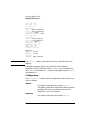
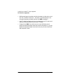
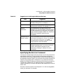
Typographic Conventions
The typographic styles used in this document are shown in Table 1.
Table 1
Typographic Conventions
Special Element
Sample of Typography
Emphasized words
back up files before deleting
Document title
HP-UX SNAplus2 Administration Guide
File or path name
/usr/spool/uucp/myfile.bkp
Directory name
/usr/spool/uucp/
Program or application
snapadmin
Parameter or Motif field
opcode; LU name
Literal value or selection that the user
can enter (including default values)
255; On node startup
Motif button
Status
Motif menu
Services
Motif menu item
Configure node parameters
User input
0p1
Computer output
CLOSE
Command or HP-UX utility
define_node; cd
General reference to all commands of a
particular type
query_* (indicates all of the
administration commands that query
details of a resource)
Option or flag
-i
Variable representing a supplied value
filename; LU_name; user_ID
Return value
0; −1
3270 key
ENTER
Keyboard keys
Ctrl+D; Enter
17
Special Element
Sample of Typography
Hexadecimal value
0x20
Environment variable
PATH
Function, call, or entry point
ioctl
Programming verb
GET_LU_STATUS
Operating System Conventions
For UNIX
This heading is used to indicate the start of a section of text that applies
only to the HP-UX operating system.
For Windows
This heading is used to indicate the start of a section of text that applies
to the Win32 client, which runs on the Microsoft NT (Version 3.51 or
later) and Windows 95 operating systems.
SNAplus2 also provides a Win16 client that runs on Microsoft Windows
3.1 and Windows for Workgroups 3.11. The Win16 client is very similar
to the Win32 client, except that you enable and configure the client
software differently.
The APIs for the Win32 and Win16 clients are fully compatible with
Microsoft SNA Server and Windows Open System Architecture (WOSA),
enabling applications written for SNA Server to run unchanged on the
Win32 and Win16 clients.
End of Section
This heading indicates the end of the operating system specific text. The
information following this heading applies regardless of the operating
system.
SNAplus2 Publications
SNAplus2 publications include user guides, administrator guides, and
programmer guides. The following sections describe the contents of each
book.
Publications for Users
SNAplus2 provides the following user guides:
18
HP-UX SNAplus2 General Information
Provides an introduction to SNAplus2 and explains key
product concepts and features.
HP-UX SNAplus2 3270/3179G Users Guide
Explains how to perform the following functions when
you use 3270 emulation:
• Starting and stopping 3270 emulation
• Transferring files
• Using customization features such as remapping
your keyboard and displaying colors
• Interpreting status-line information
• Sending NetView user alerts
• Viewing response times
HP-UX SNAplus2 RJE Users Guide
Explains how to start and stop the RJE workstation,
queue a job for submission to the host, list the queued
jobs, cancel a queued job, and send commands to the
host's job entry subsystem (JES) console.
HP-UX SNAplus2 and TN3270 Glossary
Provides a comprehensive list of terms and their
definitions used in the SNAplus2 library.
Publications for Administrators
SNAplus2 provides the following administrator guides:
HP-UX SNAplus2 Installation Guide
Explains how to install the SNAplus2 software and set
up system files.
HP-UX SNAplus2 Upgrade Guide
Provides information about upgrading to the current
version of SNAplus2 from previous versions. It includes
information about converting configuration files,
rebuilding applications that use the SNAplus2
application program interfaces (APIs), and changes in
other SNAplus2 functions.
HP-UX SNAplus2 Administration Guide
19
Explains how to enable, configure, and manage
SNAplus2. This guide provides information about SNA
concepts, and an overview of the features provided by
SNAplus2. It describes how to configure and manage
SNAplus2 using the Motif administration program and
provides guidance for users of the SNAplus2
command-line administration program.
HP-UX SNAplus2 Administration Command Reference
Explains how to use the SNAplus2 command-line
administration program and shows the syntax of all
SNAplus2 administration commands.
HP-UX SNAplus2 Diagnostics Guide
Explains how to investigate and resolve common
problems and provides an overview of diagnostic tools,
including logging and tracing.
Publications for Programmers
SNAplus2 provides the following programmer guides. Each guide
includes conceptual and detailed reference information.
HP-UX SNAplus2 APPC Programmers Guide
Contains the information you need to write application
programs using Advanced Program-to-Program
Communication (APPC).
HP-UX SNAplus2 CPI-C Programmers Guide
Contains the information you need to write application
programs using Common Programming Interface for
Communications (CPI-C).
HP-UX SNAplus2 3270 & TN3270 HLLAPI Programmers Guide
Contains the information you need to write application
programs using High-Level Language Application
Program Interface (HLLAPI).
HP-UX SNAplus2 LUA Programmers Guide
Contains the information you need to write
applications using the Conventional LU Application
Programming Interface (LUA).
HP-UX SNAplus2 CSV Programmers Guide
20
Contains the information you need to write application
programs using the Common Service Verbs (CSV)
application program interface (API).
HP-UX SNAplus2 MS Programmers Guide
Contains the information you need to write
applications using the Management Services (MS) API.
HP-UX SNAplus2 NOF Programmers Guide
Contains the information you need to write
applications using the Node Operator Facility (NOF)
API.
Related Publications
For information about SNA, APPN, or LU 6.2 architecture, refer to the
following IBM documents:
• IBM APPN Architecture and Product Implementations Tutorial,
GG24-3669
• IBM AS/400 Advanced Peer-to-Peer Networking, GG24-3287
• IBM eNetwork Communications Server for OS/2:
• APPC Programming Guide and Reference, SC31-6160
• System Management Programming Reference, SC31-6173
• IBM System/370 Principles of Operation, GA22-7000
• IBM Systems Network Architecture:
• LU 6.2 Reference—Peer Protocols, SC31-6808
• APPN Architecture Reference, SC30-3422.
• Management Services, SC30-3346
• Formats, GA27-3136
• Technical Overview, GC30-3073
21
22
1
SNA Terms and Concepts
23
SNA Terms and Concepts
Overview
Overview
This chapter defines Systems Network Architecture (SNA) terms and
concepts that are important to understanding and using SNAplus2. For
information about SNAplus2 and its capabilities, see Chapter 2,
“Introduction to SNAplus2.”
If you are already familiar with SNA and SNAplus2, you can begin with
Chapter 3, “Administering SNAplus2.”
This chapter is divided into the following parts:
• “Systems Network Architecture” provides a definition of SNA.
• “Basic SNA Concepts” explains terms and concepts that apply to any
SNA network.
• “Basic APPN Concepts” explains terms and concepts that apply only
to SNA networks that support Advanced Peer-to-Peer Networking
(APPN).
• “Basic APPN Concepts” introduces terms and concepts that apply to
networks that combine SNA and APPN.
NOTE
This chapter is not intended as a complete reference to SNA concepts.
Detailed information about SNA can be found in the SNA publications
listed in “Related Publications”.
24
Chapter 1
SNA Terms and Concepts
Systems Network Architecture
Systems Network Architecture
Systems Network Architecture (SNA) is an IBM data communication
architecture that specifies common conventions for communicating
among a wide variety of hardware and software data communication
products. This architecture consists of two kinds of definitions: formats
that define the layout of messages exchanged by network components,
and protocols that define the actions that network components take in
response to messages.
An SNA network is a collection of computers that are linked together and
communicate using SNA.
Originally, SNA was designed to enable communications with a host
computer. Each network or sub-network was controlled by the host; other
computers communicated directly with the host, but not with each other.
This older, host-controlled style of network is often referred to as subarea
SNA. SNA has since developed to support direct peer-to-peer
communications between computers in the network, without requiring a
host. This newer, peer-level networking is APPN.
Many SNA networks have elements of both subarea and peer-to-peer
networking. As networks migrate from subarea SNA to APPN, an
APPN-capable host may act to control older systems while also acting as
a peer to newer systems. Similarly, a single computer may access both
peer computers (in an APPN network) and an older host; its
communications with the host are controlled by the host, but its
communications with other computers are peer-to-peer and do not
involve the host.
Chapter 1
25
SNA Terms and Concepts
Basic SNA Concepts
Basic SNA Concepts
SNA defines the standards, protocols, and functions used by
devices—from mainframes to terminals—to enable them to communicate
with each other in SNA networks.
SNA functions are divided into a hierarchical structure of separate
layers, each performing a specific set of functions. This division of
network functions into layers enables network devices to share
information and processing resources without having detailed
information about each device on the network. A user at a workstation
can communicate with another user without knowing anything about the
physical devices on the network or the connections between those
devices.
Network Types
SNA supports the following types of networks:
• A subarea network is a hierarchically organized network consisting of
subarea nodes and peripheral nodes. Subarea nodes, such as hosts
and communication controllers, handle general network routing.
Peripheral nodes, such as terminals, attach to the network without
awareness of general network routing.
• A peer network is a cooperatively organized network consisting of
peer nodes that all participate in general network routing.
• A mixed network is a network that supports both host-controlled
communications and peer communications.
NOTE
HP-UX workstations running SNAplus2 can be part of a subarea
network, a peer network, or both.
SNA Nodes
In SNA networks, a node is a system, workstation, or other device—with
associated software components—that implements SNA protocols and
has at least one communication path to another node in the network.
26
Chapter 1
SNA Terms and Concepts
Basic SNA Concepts
Each node manages its end of the network communication paths, and
uses SNA protocols to communicate with the node at the other end of
each path.
Because subarea networks and peer networks define the relationships
among nodes differently, they also use different terms for node types (to
describe the roles that nodes play in the network).
Node Types in a Subarea Network
SNA subarea networks support the following node types:
• Subarea nodes control communication and network resources for all
attached nodes. SNA classifies subarea nodes according to their
capabilities and the amount of control they have over other nodes:
• Type 5 nodes provide SNA functions that control network
resources, support transaction programs, support network
operators, and provide end-user services. Because these functions
are often provided by host processors, type 5 nodes are also known
as host nodes. The devices and resources controlled by a type 5
subarea node constitute the domain of that node.
• Type 4 nodes provide SNA functions that route and control the
flow of data in a part of the network. Because these functions are
often provided by communication controllers, type 4 nodes are also
known as communication controller nodes.
• Peripheral nodes serve subordinate roles in subarea networks. For
example, a peripheral node can support 3270 emulation or dependent
LU 6.2 communication. Peripheral nodes are devices such as
distributed processors, cluster controllers, or workstations; they are
also classified into type 2.0 and type 2.1 nodes:
• Type 2.0 nodes are always controlled by a type 4 or 5 node. They
cannot establish communication with other nodes without the
participation of a type 4 or 5 node. Type 2.0 nodes are referred to
as dependent nodes.
• Type 2.1 nodes can act as dependent nodes, but they can also
communicate directly with other type 2.1 nodes.
NOTE
HP-UX workstations running SNAplus2 can function as type 2.1 or type
2.0 nodes.
Chapter 1
27
SNA Terms and Concepts
Basic SNA Concepts
A type 4 or 5 subarea node to which a peripheral node is attached acts as
a boundary node. It performs a boundary function by translating
between the network addresses used by a subarea node and the local
addresses used by a peripheral node.
A simple subarea network includes the following components:
Host
A host is a mainframe computer compatible with the
original IBM System/370. A host is a type 5 node.
Communication controller
A communication controller, also known as a front-end
processor (FEP), is a separate processor attached to the
host. It manages the host's communications with other
computers.
Communications link
A communications link connects the host site with an
end-user site. The users are usually on a separate site
from the host, so the two sites need to be connected by
a communications link.
Terminal controller
At the remote end of the communications link is a
terminal controller, also known as a cluster controller.
It is responsible for controlling the use of the link, and
routes data to the terminals. The most well-known
IBM terminal controllers are the 3174 and 3274.
Terminals
Users run host applications or submit work to the host
from terminals. The best-known IBM terminal is the
3270. A terminal can be connected through a terminal
controller or directly connected to a communication
controller.
Printers
Printers such as the IBM 3287 can also be attached to
the terminal controller. They can receive output from
the host.
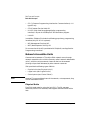
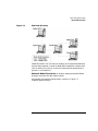
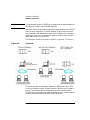
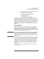
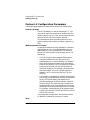
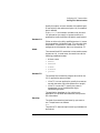
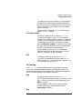
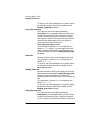
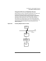
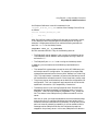
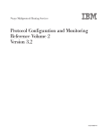
As shown in Figure 1-1, “SNA Subarea Network,” a diagram of a subarea
network looks like an inverted tree.
28
Chapter 1
SNA Terms and Concepts
Basic SNA Concepts
Figure 1-1
SNA Subarea Network
The root of the tree (at the top of the diagram) is the computer
controlling the network. The branches are the communications links
from the host to the other computers in the network (terminal
controllers); the leaves (at the bottom of the diagram) are the terminals
or printers attached to these computers, which are accessed by users.
The traditional subarea SNA set-up described here enables the users to
use the resources of a single host system. The terminals provide only
simple data entry and display functions to and from the terminal
controller; the terminal controller is responsible for handling SNA
communications between the terminals and the host.
The terminal controller and its terminals can be replaced by an SNA
node using a product such as SNAplus2. From the host's point of view,
the node appears as a terminal controller. However, it provides the users
with additional functions, such as the ability to access more than one
host system and facilities for customizing screen displays. In addition,
SNAplus2 runs on HP-UX computers that can also be used for other
tasks not related to SNA (unlike the terminal controller, which is used
solely for communications with the host).
Chapter 1
29
SNA Terms and Concepts
Basic SNA Concepts
Node Types in a Peer Network
Peer networks do not classify nodes hierarchically, as is done in a
subarea network. Exchanges with other nodes are not controlled by a
host or other centralized processor. Instead, any node can establish
communication with any other node.
A peer network is composed of type 2.1 nodes. The nodes in a peer
network can serve the following roles:
• APPN network nodes (NNs) identify the locations of network
resources, determine routes for sessions between these resources,
route sessions, and serve end nodes (EN) and low-entry networking
(LEN) nodes directly attached to the network node. The domain of an
APPN network node consists of itself and any end nodes for which it
provides network services.
• APPN end nodes can access remote resources without requiring that
those resources be configured on the end node. An end node can
communicate with adjacent nodes on its own, but requires the
services of a network node server to access nonadjacent nodes. The
domain of an APPN end node includes only itself.
• Low-entry networking nodes (LEN nodes) are type 2.1 nodes that do
not support APPN functions. They can communicate with adjacent
nodes in an APPN network, but do not participate in the APPN
network. In a LEN node, all potential sessions with remote LUs must
be predefined, either specifically or through a single default entry
indicating that all remote LUs reside in an adjacent network node
that can be accessed using a certain link. The domain of a LEN node
includes only itself.
For more information about peer-oriented node types, see “APPN Node
Types”.
Connectivity
For two nodes to communicate, each node must have a combination of
hardware and software that supports data flow between the nodes. The
hardware component consists of an adapter at each node and the
transmission medium that connects the two adapters. The software
component provides control of the hardware and the data exchanged over
it.
30
Chapter 1
SNA Terms and Concepts
Basic SNA Concepts
Each node connected to a network has one or more link stations, which
are the hardware and software in a node that control data flow to a
specific adjacent node. To establish communication between two adjacent
nodes, one of the link stations must first activate the link between the
nodes.
Transaction Programs
Programs that exchange information across the SNA network are called
transaction programs (TPs).
Following are examples of application programs that can include SNA
TPs:
• Emulation programs
• File transfer
• Database transaction processing
• Network management
• Centralized data services
The TP accesses the network through a logical unit (LU) that establishes
and maintains a session with a partner LU on another node. For more
information about logical units, see “Logical Units”.
NOTE
SNAplus2 includes sample TPs for most supported APIs. For more
information on sample TPs, refer to the programmer's guide for the API.
You can also purchase SNA TPs as part of other products or create your
own TPs (see “Application Programming Interfaces”).
Application Programming Interfaces
SNA TPs are written using application programming interfaces (APIs).
APIs provide specific subroutines that enable SNA TPs to access SNA
functions, such as those for exchanging data and performing control
functions. These subroutines enable an SNA TP to communicate with
another SNA TP on a remote node.
SNAplus2 includes the following APIs on all platforms:
• APPC—LU type 6.2 only
Chapter 1
31
SNA Terms and Concepts
Basic SNA Concepts
• CPI-C (Common Programming Interface for Communications)—LU
type 6.2 only
• CSV (Common Service Verb) API
• HLLAPI (high-level language application programming
interface)—as part of the SNAplus2 3270 emulation program
• LUA API
In addition, SNAplus2 includes the following proprietary programming
interfaces (only for HP-UX systems):
• MS (Management Services) API
• NOF (Node Operator Facility) API
For an overview of the APIs provided with SNAplus2, see “Application
Programming Interfaces”.
Network Accessible Units
Communication between a TP and the SNA network occurs through
network accessible units or NAUs (formerly called “network addressable
units”), which are unique network resources that can be accessed
(through unique local addresses) by other network resources.
SNA provides the following types of NAUs:
• Physical units (see “Physical Units”)
• Logical units (see “Logical Units”)
• Control points (see “Control Points”)
NOTE
Because TPs are considered users of the network, not components, they
are not classified as NAUs.
Physical Units
Each SNA node contains a physical unit (PU). The PU manages
resources (such as link resources) and supports communication with a
host.
32
Chapter 1
SNA Terms and Concepts
Basic SNA Concepts
NOTE
On type 2.1 nodes (which can be APPN nodes), the control point provides
PU services in addition to providing other services (see “Control Points”).
Two type 2.1 nodes (such as SNAplus2 nodes) can communicate directly,
without requiring the services of a host to establish communications.
Logical Units
Each SNA node contains one or more logical units (LUs). An LU provides
a set of functions that are used by TPs and end users to provide access to
the network. LUs communicate directly with local TPs and devices.
SNA defines several types of LUs, each optimized for a specific class of
applications. LUs of different types cannot communicate with each other,
but LUs of the same type can communicate even though they reside on
different kinds of systems.
For example, a TP running on a workstation that uses the HP-UX
operating system can communicate with a TP on an AS/400 computer as
easily as it can with a TP on another HP-UX workstation, as long as both
TPs use the same LU type.
SNAplus2 supports the following LU types:
LU 6.2 (for APPC, 5250 and CPI-C)
LU 6.2 supports program-to-program communication
in a distributed data processing environment. The LU
6.2 data stream is either an SNA general data stream
(GDS), which is a structured-field data stream, or a
user-defined data stream. LU 6.2 can be used for
communication between two type 5 nodes, a type 5
node and a type 2.0 or 2.1 node, or two type 2.1 nodes.
(Type 2.1 nodes can serve as APPN nodes.)
This LU type provides more functions and greater
flexibility than any other LU type. Unless you are
constrained by existing hardware or software, LU 6.2 is
the logical choice when developing new applications.
NOTE
Only LU 6.2 can provide independent LU functions.
LU 3 (for 3270 printing)
LU 3 supports application programs and printers using
the SNA 3270 data stream.
Chapter 1
33
SNA Terms and Concepts
Basic SNA Concepts
For example, LU 3 can support an application program
running under Customer Information Control System
(CICS) and sending data to an IBM 3262 printer
attached to an IBM 3174 Establishment Controller.
LU 2 (for 3270 displays)
LU 2 supports application programs and display
workstations communicating in an interactive
environment using the SNA 3270 data stream. Type 2
LUs also use the SNA 3270 data stream for file
transfer.
For example, the LU 2 protocol can support 3270
emulation programs, which enable workstations to
perform the functions of IBM 3270-family terminals. In
addition, LU 2 is used by other programs to
communicate with host applications that normally
provide output to 3270 display devices. Such TPs
enable the workstation to achieve a form of cooperative
processing with the host.
LU 1 (for 3270 printing and RJE)
LU 1 supports application programs and single- or
multiple-device data processing workstations
communicating in an interactive, batch-data transfer,
or distributed data processing environment. The data
streams used by LU type 1 conform to the SNA
character string or Document Content Architecture
(DCA).
For example, LU type 1 can support an application
program running under Information Management
System/Virtual Storage (IMS/VS) and communicating
with an IBM 8100 Information System. This enables a
workstation operator to correct a database that the
application program maintains.
Applications that use LU 1 are often described as
remote job entry (RJE) applications.
LU 0 (for LUA)
LU 0, an early LU definition, supports primitive
program-to-program communication. Certain host
database systems, such as IMS/VS (Information
Management System/Virtual Storage) and some
point-of-sale systems for the retail and banking
industries (such as the IBM 4680 Store System
34
Chapter 1
SNA Terms and Concepts
Basic SNA Concepts
Operating System) use LU 0. Current releases of these
products also support LU 6.2 communication, which is
the preferred protocol for new applications.
NOTE
For information about the data streams used by SNA logical units, refer
to Systems Network Architecture Technical Reference.
Control Points
A control point (CP) is an NAU that manages network resources within
its domain, controlling resource activation, deactivation, and status
monitoring. The CP manages both physical resources such as links, and
logical information such as network addresses.
SNA defines the following types of network control points:
System services control point
On a type 5 node, the CP is called a system services
control point (SSCP). It manages and controls the
network resources in a subarea network. For example,
an SSCP can use a directory of network resources to
locate a specific LU under its control, and can establish
communication between two LUs in its domain. An
SSCP can also cooperate with other SSCPs to establish
connectivity between LUs in different subarea
domains.
The SSCP also provides an interface to network
operators at the host system, who can inspect and
control resources in the network.
Physical unit control point
On type 4 nodes and type 2.0 nodes in a subarea
network, the control point is called a physical unit
control point (PUCP).
Control point
On type 2.1 nodes, the control point provides both PU
and LU functions, such as activating local link stations,
interacting with a local operator, and managing local
resources. It can also provide network services, such as
partner LU location and route selection for local LUs.
Chapter 1
35
SNA Terms and Concepts
Basic SNA Concepts
In a subarea network, the CP on an SNA node acts as a
type 2.0 PU. It communicates with an SSCP on a host
and does not communicate with other CPs in the
subarea network.
When participating in an APPN network, the CP
exchanges network control information with the CPs in
adjacent nodes. The CP can also function as an
independent LU of type 6.2. The CP acts as the default
LU for TPs on the local node. For more information
about the APPN control point, see “APPN Control
Point”.
Sessions
NAUs communicate with NAUs in other nodes over temporary logical
communication channels called sessions. Before two TPs can
communicate, their LUs must establish a session. The LU that manages
the session on the local node is the local LU; the LU that manages the
session on the remote node is the partner LU.
Session Types
SNAplus2 is primarily concerned with the following types of sessions:
LU-LU sessions
In order for two TPs to communicate, the LUs that
support the TPs must first establish an LU-LU session.
In general, a session is established when a TP in one
SNA node tries to communicate with a TP in another
node and no existing session between the LUs on the
two nodes is available.
SSCP-LU sessions
A dependent LU (see “Dependent and Independent
LUs”) must have an active SSCP-LU session with an
SSCP on a type 5 node before it can have a session with
an LU in the subarea network. Once an SSCP-LU
session is active, a dependent LU can solicit an LU-LU
session.
SSCP-PU sessions
36
Chapter 1
SNA Terms and Concepts
Basic SNA Concepts
Before an SSCP-LU session can be established, the PU
controlling the LU must have an active SSCP-PU
session with an SSCP on a type 5 node. The SSCP-PU
session is used to pass control data and network
management data between the PU and SSCP.
CP-CP sessions
In an APPN network, adjacent nodes establish CP-CP
sessions. These sessions are used to search for a
resource in the APPN network and to maintain
topology information (see “APPN Control Point”).
Logical Unit Attributes for Sessions
Logical units have attributes that determine how they interact during
LU-LU sessions. These attributes are determined by the architecture of
SNA. LUs can be primary or secondary, and dependent or independent.
Primary and Secondary LUs. To establish a session, one LU
requests session activation by sending a BIND request to another LU:
• A primary LU is the LU that sends the BIND request for a given
LU-LU session.
• A secondary LU is the LU that receives the BIND request.
Peer networks do not use a fixed hierarchy of nodes and do not have
predetermined primary or secondary LUs.
NOTE
In a peer network, an independent LU that is participating in multiple
sessions (see “Multiple and Parallel Sessions”) can act as a primary LU
for one session and a secondary LU in another.
Dependent and Independent LUs. All type 0, 1, 2, and 3 LUs are
dependent LUs. Type 6.2 LUs can be configured as either dependent or
independent LUs.
• A dependent LU (also known as an SSCP-dependent LU) requires the
services of an SSCP to establish a session with another LU. An
SSCP-LU session must be established before a dependent LU-LU
session can be established.
A dependent LU can be in session only with LUs on an SNA host.
Because of this restriction, dependent LUs usually use subarea
networks (also known as host-mediated networks). However, the
Chapter 1
37
SNA Terms and Concepts
Basic SNA Concepts
dependent LU requester (DLUR) function enables session traffic from
dependent LUs to flow over APPN networks. For more information
about DLUR, see “Accessing Subarea Networks from APPN
Networks”.
A dependent LU on a peripheral node is always the secondary LU.
• An independent LU can establish sessions with other independent
LUs without the aid of an SNA host. LU 6.2 is the only LU type that
can be independent.
An independent LU can act as a primary or as a secondary LU when
establishing a session.
Multiple and Parallel Sessions
An independent LU can participate in sessions with more than one
remote LU at the same time (multiple sessions).
An independent LU can also participate in parallel sessions, or multiple
concurrent sessions with the same remote LU.
Dependent LUs (including dependent LU 6.2) cannot have multiple
sessions.
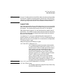
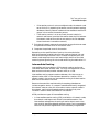
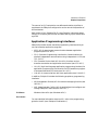
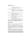
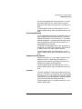
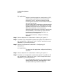
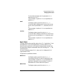
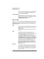
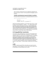
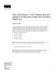
LUs with multiple and parallel sessions are shown in Figure 1-2,
“Multiple and Parallel Sessions.” LUA and LUB have parallel sessions.
LUA also has multiple sessions: two with LUB and one with LUD. LUD
has multiple sessions with LUA and LUC.
38
Chapter 1
SNA Terms and Concepts
Basic SNA Concepts
Figure 1-2
Multiple and Parallel Sessions
Conversations
This section applies to LU 6.2 only.
Once a session is established between two LUs, the LU-LU session
supports the exchange of information between two TPs, which have the
exclusive use of the session to execute a transaction. This exchange of
information is called a conversation. Only one conversation can use a
particular session at a time, but sessions are serially reusable (many
conversations can use the same session, one after another).
To initiate a conversation, a source TP sends a request to its LU, asking
it to allocate a conversation with a remote TP. The invoking TP (or
source TP) initiates the conversation, like the calling party in a
telephone conversation. The invokable TP or target TP (the remote TP) is
the partner in the conversation, like the party who receives a telephone
call.
Chapter 1
39
SNA Terms and Concepts
Basic SNA Concepts
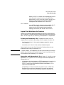
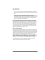
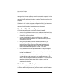
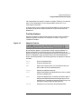
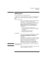
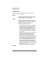
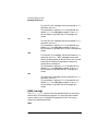
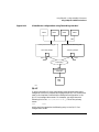
As shown in Figure 1-3, “Communication between Transaction Programs
and Logical Units,” information is exchanged between TPs and LUs to
enable one node to communicate with another. Although the TPs appear
to be communicating directly, the LUs on each node are the
intermediaries in every exchange.
Figure 1-3
Communication between Transaction Programs and Logical
Units
SNA defines two types of conversations: basic and mapped. These two
types of conversations use different methods to indicate the length of
transmitted or received data packages to be passed between SNAplus2
and the TP.
• In a basic conversation, data must be formatted by the TP as logical
records before being presented to the SEND function.
40
Chapter 1
SNA Terms and Concepts
Basic SNA Concepts
A logical record consists of a two- or four-byte header starting with a
two-byte length field, often represented as “LL,” followed by up to
32,765 bytes of data. Logical records can be grouped together and
sent as a block, transmitting more than one logical record with a
single call to the SEND function.
• In a mapped conversation, information is passed to the SEND function
as a pointer to a single, unformatted block of data; the length of the
block is passed as another parameter. The block cannot be received as
one or more logical records; the receiving TP must do whatever
record-level formatting is required.
NOTE
Only LU type 6.2 supports mapped conversations.
Modes
Each LU-LU session has an associated mode that defines a set of session
characteristics. These session characteristics include throughput
parameters, session limits (such as the maximum number of sessions
between two LUs), message sizes, and routing parameters.
Each mode is identified by a unique mode name. The mode name must be
the same on all SNA nodes that use that mode.
Route Selection
To establish an LU-LU session, a route must be calculated between the
nodes where the two LUs reside. A route is an ordered sequence of links
and nodes that represents a path between the two nodes.
SNA networks support the following methods of route selection:
• For subarea networks, you must predefine all routes between subarea
nodes.
• For peer networks that do not support APPN, type 2.1 nodes can
support sessions only with adjacent nodes; their sessions cannot be
routed through intermediate nodes.
• For APPN networks, SNA can compute routes dynamically at the
time of session initiation, using a class of service specified for the
mode used by the session (see “Class of Service”).
Chapter 1
41
SNA Terms and Concepts
Basic SNA Concepts
Class of Service
Class of service (COS) is a definition of the transport network (data link
control and path control) characteristics—such as route security,
transmission priority, and bandwidth—that the local node can use to
establish a particular session. The COS definition assigns relative values
to factors such as acceptable levels of security, cost per byte, cost per
connect-time, propagation delay, and effective capacity.
In a subarea network, a COS is derived from the mode associated with a
session, as defined in the host system.
APPN network nodes use the COS to compute session routes between
independent LUs. For more information about session routing in APPN
networks, see “Session Routing”.
42
Chapter 1
SNA Terms and Concepts
Basic APPN Concepts
Basic APPN Concepts
Advanced Peer-to-Peer Networking (APPN) is a network architecture
that supports distributed network control. It makes networks easy to
configure and use, provides centralized network management, and
supports flexible connectivity.
An APPN network is composed of type 2.1 nodes. Each node in the
network is connected by a link to at least one other node in the APPN
network. CP-CP sessions are established over each of these links to
adjacent nodes (nodes in the same network that can establish direct
links without going through a third node). All of the nodes in an APPN
network share a common network name.
APPN nodes can include processors of various sizes, such as the
Application System/400 (AS/400), the Enterprise System/9221 (ES/9221)
running under Distributed Processing Program Executive/370
(DPPX/370), systems using Virtual Terminal Access Method (VTAM),
and HP-UX servers running SNAplus2.
APPN provides the following functions:
• Support for APPN network nodes and end nodes as well as non-APPN
peer nodes (see “APPN Node Types”)
• APPN control point functions (see “APPN Control Point”)
• Directory services to support finding specific logical units (see
“Locating Resources”)
• Topology and routing services to support session establishment using
intermediate session routing (ISR), automatic network routing
(ANR), or connection networks (CNs) (see “Session Routing” and
“APPN Connection Networks”)
NOTE
An APPN node can also be connected to a subarea network, serving as
both an APPN node in a peer network and a peripheral node in a subarea
network.
APPN Node Types
The following types of nodes can be part of an APPN network:
Chapter 1
43
SNA Terms and Concepts
Basic APPN Concepts
• Network nodes (see “APPN Network Nodes”)
• End nodes (see “APPN End Nodes”)
In addition, low-entry networking (LEN) nodes can be connected to an
APPN network, but they do not use APPN features (see “LEN Nodes”).
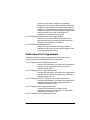
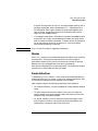
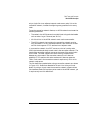
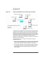
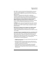
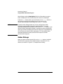
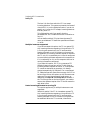
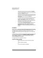
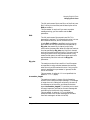
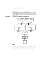
A sample APPN network that includes all of these node types is shown in
Figure 1-4, “Portion of a Sample APPN Network.”
Figure 1-4
Portion of a Sample APPN Network
This example shows an APPN network that includes five network nodes
(NNs), three end nodes (ENs), and a LEN node. The network nodes form
the backbone of the APPN network; end nodes access the network
through the network nodes. LU 6.2 TPs on any node can communicate
with any other LU 6.2 TPs in the network.
44
Chapter 1
SNA Terms and Concepts
Basic APPN Concepts
One of the APPN network nodes (NNA) also participates in a subarea
network, connecting to a host through a communication controller. This
node functions as an APPN node when communicating with nodes in the
APPN network, and as a peripheral node when communicating with
nodes in the subarea network. Through this network node, LU type 6.2
LUs on other nodes in the APPN network can establish LU-LU sessions
with LU type 6.2 LUs on the host.
APPN Network Nodes
An APPN network node is a type 2.1 node that provides distributed
directory and routing services for all LUs in its domain. These LUs can
be located on the network node itself, or on an APPN end node or LEN
node for which the network node provides services. Because an APPN
network node acts as the network entry point for end and LEN nodes in
its domain, the network node is also referred to as the network node
server for those nodes.
A network node provides the following services:
• LU-LU session services for its local LUs
• Directory searches and route selection for all LUs in its domain
• Intermediate session routing (see “Intermediate Routing”)
• Routing for management services (MS) data, such as alerts, between
a served end node and an MS focal point
APPN End Nodes
An APPN end node is a type 2.1 node that serves as an end point in an
APPN network. It maintains directory information only for local
resources. An APPN end node can independently establish sessions
between local LUs and LUs on adjacent nodes. For sessions with LUs on
nodes not directly connected to the end node, an end node requests
routing and directory information from its network node server using
CP-CP sessions.
APPN end nodes can register their local LUs with their network node
server. This capability means the network operator at the network node
server does not have to predefine the names of all LUs on the attached
end nodes to which the network node provides services.
Chapter 1
45
SNA Terms and Concepts
Basic APPN Concepts
An APPN end node can be attached to multiple network nodes (see EN3
in Figure 1-4, “Portion of a Sample APPN Network,”) but it can have
CP-CP sessions active with only one network node at a time—its
network node server. The other network nodes can be used only to
provide intermediate routing for the end node or as substitute network
node servers if the main network node server becomes unavailable.
An APPN end node can also have a direct link to another APPN end node
or a LEN node, but CP-CP sessions are never established between two
end nodes.
LEN Nodes
A low-entry networking node (LEN node) is a type 2.1 node that uses
independent LU 6.2 protocols, but does not support CP-CP sessions. It
can be connected to an APPN network node or end node, but does not
support APPN functions.
An APPN network node can provide routing services for an attached
LEN node, enabling the LEN node to participate in an APPN network
without requiring link stations to be defined between the LEN node and
all of the nodes in the APPN network.
LUs in the APPN network with which the LEN node may want to
establish sessions must be defined to the LEN node as if they reside on
the LEN node's network node server. The LEN node establishes sessions
with LUs on its network node server. The network node routes the
session through the APPN network to the node in the network where the
LU actually resides. LUs on the LEN node must be predefined to the
network node that serves the LEN node. LU resources on LEN nodes
(unlike those on end nodes) cannot be registered on the network node
server.
An APPN end node cannot provide intermediate routing. When a LEN
node's only link is to an APPN end node, the LEN node can communicate
only with LUs on the end node through the direct link between the two
nodes.
46
Chapter 1
SNA Terms and Concepts
Basic APPN Concepts
APPN Control Point
An APPN control point is a set of functions that manages node resources
and supports both physical unit and logical unit functions on a type 2.1
node. An APPN CP directs local node functions (such as activating and
deactivating adapters and links), provides directory and topology
information, and assists LUs in session initiation and termination.
Adjacent nodes in an APPN network use a pair of parallel CP-CP
sessions to exchange network information and to provide directory and
route selection services. Both sessions of a given pair must be active in
order for the partner CPs to begin and sustain their interactions.
Different node types use these sessions differently, as follows:
• Two parallel CP-CP sessions are established between an APPN
network node and each adjacent network node. These CP-CP sessions
are used to exchange directory, topology, and management services
data.
• Two parallel sessions are established between an APPN end node and
the adjacent network node acting as the server for the end node.
These CP-CP sessions are used to exchange directory, topology, and
management services data.
• LEN nodes do not support CP-CP sessions.
The functions provided in CP-CP sessions vary based on the types of
nodes involved, as follows:
• All CP-CP sessions conduct directory searches.
• CP-CP sessions between an end node and a network node provide the
following functions:
• Registering resources.
• Routing management services data (such as alerts) between the
end node and a focal point.
• Routing topology data from each end node to its network node
servers. This information can be used by the network node server
to compute a route that does not flow through the network node
server.
• CP-CP sessions between adjacent network nodes exchange topology
information. As a result of this exchange, each network node creates
an internal network topology database.
Chapter 1
47
SNA Terms and Concepts
Basic APPN Concepts
When setting up a workstation, you must define the CP name. The CP is
also an LU that can support user sessions, and it can be the only LU
defined in your workstation, if you so choose.
Locating Resources
To support communication between TPs, SNAplus2 first establishes a
session between the logical units that control those TPs. APPN enables
the CP on a node to locate LUs throughout the APPN network without
requiring that the node have any configuration information for the
remote LU. The APPN function that dynamically locates LUs in the
network is called directory services. Once a resource has been located, a
route for the session is calculated through the APPN network.
Resource Names
Each node has a unique name consisting of two parts: a network name
and a control point name. Together they constitute a fully qualified CP
name. This name identifies each node to all other nodes in the network.
Similarly, each logical unit is identified by a fully qualified LU name,
consisting of a network name and LU name.
Directory Services
Each APPN node maintains a directory of network resources. Directory
services is the component of the node CP that manages the local
directory database and, in a network node, searches for network
resources throughout an APPN network.
When the node is initialized, it includes the following information:
• Node type (APPN network node, APPN end node, or LEN node)
• Network ID of node
• CP name of node
Each node directory maintains entries for resources (LUs and CPs),
including each resource's fully qualified name, type, and registration
status. The specific resources stored in each local directory depend on the
node type:
• A LEN node maintains a directory that includes its own LUs. It must
also be configured with directory entries for all of its possible partner
LUs. LUs in the APPN network with which the LEN node may want
to establish sessions must be defined to the LEN node as if they
48
Chapter 1
SNA Terms and Concepts
Basic APPN Concepts
reside on the LEN node's network node server. The LEN node
establishes sessions with LUs on its network node server. The
network node routes the session through the APPN network to the
proper node in the network.
A LEN node can also use wildcards in a directory entry to specify
multiple partner LUs that can be accessed over a specific link.
• An APPN end node maintains a directory that includes its own LUs.
It can also be configured to store directory entries for partner LUs in
adjacent nodes. This enables local LUs to establish peer-to-peer
sessions with those LUs without using APPN functions.
If a resource is not locally defined to an end node or currently cannot
be reached by the end node, the end node sends a request to its
network node server asking it to search the APPN network for the
resource.
• An APPN network node maintains a directory that includes its own
LUs and the end node and LEN node LUs in its domain. An end node
can dynamically register its LUs with its network node server. (LEN
nodes cannot register LUs with a network node server, so LEN node
LUs must be configured on their network node server.) A network
node directory can also contain cached entries for LUs that are not in
the network node's domain, but whose location has been determined
through a previous search.
Network nodes provide directory services to other nodes in two ways:
• Searching for remote resources in response to session requests
from end nodes or LEN nodes
• Responding positively to directory search requests from other
network nodes when a named resource is found in the local
directory
LEN Node Directories. An example of a LEN node directory is
shown in Figure 1-5, “LEN Node Directory.” Since LEN nodes do not
support CP-CP sessions, the directory for Node LEN1 must contain all
the LUs with which it communicates. The directory for Node LEN1
identifies its network node server (NNA) as the location for any LUs that
are not on an adjacent peer end node. Since Node LEN1 can access the
LUs only through Node NNA, it defines the CP on the network node as
the “owning CP” of all the LUs, including LUs located on the end nodes.
Chapter 1
49
SNA Terms and Concepts
Basic APPN Concepts
Figure 1-5
LEN Node Directory
To establish a session with an LU on a node that is not directly attached,
Node LEN1 sends an LU-LU session activation (BIND) request to its
network node server (Node NNA). The server automatically locates the
destination LU and forwards the BIND.
NOTE
In this example, Node LEN1 can establish a session with LU1 on Node
EN1 through its network node server, NNA. However, LU2 on Node EN1
is not defined in the directory for Node LEN1, so Node LEN1 cannot
establish sessions with that LU.
End Node Directories. When an LU is not represented in an end
node directory, the end node initiates a LOCATE search to find the desired
LU. To activate the search for a remote LU, the end node invokes the
services of its network node server. An example of an end node directory
is shown in Figure 1-6, “End Node Directory.”
50
Chapter 1
SNA Terms and Concepts
Basic APPN Concepts
Figure 1-6
End Node Directory
Potential partner LUs in the APPN network do not need to be defined to
the end node. However, in order for Node EN3 to establish a session with
LUX on Node LEN1, the LU on the LEN node must be configured as a
partner LU on Node EN3.
Network Node Directories. A network node provides distributed
directory services to the end nodes it serves.
An example of a network node directory is shown in Figure 1-7,
“Network Node Directory.”
Chapter 1
51
SNA Terms and Concepts
Basic APPN Concepts
Figure 1-7
Network Node Directory
A network node locates a remote LU as follows:
1. The network node receives a request to locate an LU. The request can
be any of the following:
• The name of a destination LU sent by an end node or a LEN node
to its network node server
• An LU name specified in a LOCATE search request from an end
node
• An LU name specified in a BIND request from a LEN node
• An LU name specified by a TP on the network node
2. If the destination LU is not located in the network node—but appears
in its directory—the network node sends a directed search request to
the destination network node server to verify the location of the LU.
If the LU is not in the network node directory, the node initiates a
search of the network by sending a broadcast search to every adjacent
network node.
3. Each node in turn propagates the broadcast and returns replies
indicating success or failure.
For its future needs, a network node caches information obtained from
successful broadcast searches.
52
Chapter 1
SNA Terms and Concepts
Basic APPN Concepts
An APPN end node can also receive (and respond to) LOCATE search
requests from its network node server to search for, or confirm the
continued presence of, specific LUs in the end node.
Each APPN end node registers its LUs with its network node server by
sending the network node a registration message. In this way, the
network node maintains current directory information for the end nodes
in its domain. A LEN node cannot register LUs with its network node
server. Therefore, all LUs on the LEN node must be predefined, through
configuration, to the network node server.
Session Routing
APPN supports the following dynamic route selection procedures:
• For sessions with adjacent nodes, direct session routing.
• For sessions that traverse one or more intermediate nodes, one of the
following:
• Intermediate session routing (ISR), which provides a route that
does not change during the course of the session.
• High-Performance Routing (HPR), which includes the Rapid
Transport Protocol (RTP) and automatic network routing (ANR)
facilities. RTP enables you to reroute session traffic around route
failures or congestion, and ANR minimizes cycles and storage
requirements for routing network layer packets through
intermediate nodes on a session route.
The APPN functions that provide dynamic route selection are known as
topology and routing services (TRS).
Topology and Routing Services
Each APPN node includes a topology database that stores information
about other APPN nodes and about transmission groups, which are sets
of links between a specific pair of nodes. The contents of the database for
a specific node depend on the node type:
• All network nodes share a copy of the network topology database.
This shared database includes information about all other network
nodes—including network IDs, CP names, and other node
characteristics—and about the transmission groups between each
pair of network nodes. This database provides a complete view of the
Chapter 1
53
SNA Terms and Concepts
Basic APPN Concepts
network backbone topology—the nodes and transmission groups that
can be used for routing sessions between any pair of nodes in the
network.
In addition, the topology database on each network node contains
local information about transmission groups from that network node
to adjacent end nodes or LEN nodes.
The network node uses the topology database to calculate routes for
sessions between LUs in its domain and remote LUs, or to provide
information to other network nodes to enable them to calculate
session routes.
• Each end node has a local topology database with information about
transmission groups from that end node to adjacent nodes.
The end node provides this information to its network node server as
part of the request to locate an LU and calculate a session route to
that LU. The network node server uses the end node topology
information when calculating the session route for the end node. The
end node uses this information when establishing sessions with
predefined LUs on adjacent nodes. The end node topology database
supports communication only with adjacent nodes.
NOTE
APPN network nodes and end nodes also maintain topology information
about links to a connection network (see “APPN Connection Networks”).
LEN nodes maintain local topology information. They do not forward this
information to a network node server.
As shown in Figure 1-8, “Network Topology Database in Network
Nodes,” network topology information is replicated at all network nodes,
and local topology information is stored at network nodes and end nodes.
54
Chapter 1
SNA Terms and Concepts
Basic APPN Concepts
Figure 1-8
Network Topology Database in Network Nodes
The shared network topology database is duplicated at Nodes NNA,
NNB, NNC, and NND. In addition, each of those nodes includes local
topology information (except Node NNC, which does not have any local
Chapter 1
55
SNA Terms and Concepts
Basic APPN Concepts
topology information because it does not have any links to end nodes).
For example, Node NNB includes information for Link f to Node EN2
and Link g to Node EN3, but it does not include information for Link i,
which connects Nodes EN2 and EN3.
End nodes include information only for links to adjacent nodes. For
example, Node EN2 includes information about Link f to Node NNB and
Link i to Node EN3.
Topology Database Updates. APPN network nodes use CP-CP
sessions to exchange network topology information when a resource
(such as a node or a link between two network nodes) is activated or
deactivated, or when the characteristics of an existing resource change.
When such a change occurs, a network node generates a topology
database update (TDU) that contains node identification node and link
characteristics, and update sequence numbers identifying the resource to
be updated and the changes for the resource. Each TDU is sent to all
active network nodes to ensure that the network topology database is
kept current throughout the network.
Route Selection in an APPN Network. APPN directory services
locates a specific session partner; topology and routing services
calculates the optimal session route after the session partner has been
located in the network. Each network node provides route selection
services for sessions originated by its own LUs and by LUs at the end
nodes or LEN nodes that it serves. A network node uses its own local
topology information, plus information from the shared network topology
database, to dynamically calculate routes between nodes.
Once the session partner has been located, the network node performs
the following steps to select a route:
1. Obtains required characteristics for the session route.
The LU requesting the session specifies a mode name that identifies
session characteristics. The associated mode identifies a class of
service that specifies requirements for the links used to route session
traffic.
2. Obtains all transmission groups and network nodes for possible
routes:
• If the session request comes from an end node, the end node
provides information about links it has to its network node server
and to a connection network, if one exists.
56
Chapter 1
SNA Terms and Concepts
Basic APPN Concepts
• If the session partner is not on an adjacent node, the network node
server for the LU requesting the session uses the network topology
database to identify network nodes and intermediate transmission
groups in the route to the session partner.
• If the session partner is on an end node, the end node (or its
network node server) provides information about the link between
the network node server and that end node (or the link between
the end node and a connection network).
3. Excludes all network nodes and transmission groups that do not meet
the specified characteristics for the session route.
4. Computes the optimal route for the session.
Depending on the specified class of service, the route calculation
algorithm computes a weight value for each node and logical link and
then totals the weights for each route. To select the optimal path, the
network node computes the current least-weight route from the node
containing the originating LU to the node containing the destination LU.
Intermediate Routing
Intermediate routing enables an APPN network node to receive and
route data destined for another node. The origin and destination of the
data can be an end node, another network node, or a LEN.
Intermediate routing supports sessions between LUs that are not on
adjacent nodes. After a route has been selected for a session, APPN
network nodes in the route use intermediate routing to forward session
data to the next node in the route.
Resource characteristics maintained by the topology database can
include congestion status. If a network node becomes heavily congested,
the network node can relay this information to other network nodes in
the network, making the congested network node less likely to be
included in session routes calculated for new sessions.
APPN provides two types of intermediate routing:
• In intermediate session routing (ISR), available in all network nodes,
the network node keeps track of each intermediate session. Each
intermediate node adjusts the pacing of session data to control the
rate at which data flows between adjacent nodes. Each intermediate
node can also perform segmentation and reassembly of segmented
Chapter 1
57
SNA Terms and Concepts
Basic APPN Concepts
data. In ISR, once a session route has been established, all data on
that session uses the same route. If part of the route fails, the session
ends.
• In automatic network routing (ANR), available in network nodes that
support APPN's High-Performance Routing (HPR) function,
intermediate network nodes can dynamically reroute session traffic if
part of the route fails. ANR does not provide intermediate session
pacing or segmentation and reassembly.
ANR enables intermediate nodes to route session traffic much faster
than is possible with traditional APPN ISR. However, ANR requires
additional overhead at the RTP (Rapid Transport Protocol) endpoints. In
routes with few intermediate nodes, an ANR route might actually be
slower than an ISR route, due to processing time at the endpoints. For
routes containing a larger number of intermediate nodes (hops), ANR
routes are typically faster. The exact location of the break-even point
depends on the efficiency of the RTP nodes.
Direct Connectivity
Direct connectivity enables session traffic to travel directly between two
nodes without the need for an APPN network node to route the session.
In general, sessions between directly connected nodes can exchange data
more quickly than sessions for which data is routed through a network
node. For nodes on a shared-access transport facility (SATF)—for
example, for nodes on a token ring as shown in Figure 1-9—efficiency
would be increased by defining links between every pair of nodes in your
network. However, this can be a difficult task—the number of link
stations is n × (n−1), where n is the number of nodes in the network.
An APPN network on a token ring is shown in Figure 1-9, “APPN
Network Using a Shared-Access Transport Facility.”
58
Chapter 1
SNA Terms and Concepts
Basic APPN Concepts
Figure 1-9
APPN Network Using a Shared-Access Transport Facility
If Node EN1 has a link definition for each of the links in the network, it
can establish a direct link to any node. The link definitions needed to
support direct links between Node EN1 and every other node in the
APPN network are shown in Figure 1-10, “Definitions Needed for Direct
Links from Node EN1 to Every Node in an APPN Network.” For a
network that includes five other nodes, Node EN1 needs five link
definitions:
• EN1 to NNA
• EN1 to EN2
• EN1 to EN3
• EN1 to EN4
• EN1 to EN5
Chapter 1
59
SNA Terms and Concepts
Basic APPN Concepts
Figure 1-10
Definitions Needed for Direct Links from Node EN1 to Every
Node in an APPN Network
If all of the nodes in the network are to support direct links to every
other node, a total of 30 link definitions are needed on the six nodes in
this example. In general, the number of link definitions can be calculated
as n × (n−1), where n is the number of nodes in the network. In a larger
network, the number of link definitions quickly becomes unwieldy.
Increasing the number of link definitions between network nodes also
increases the number of TDUs flowing through the network, which can
degrade network performance.
APPN connection networks provide a solution to this problem.
APPN Connection Networks
For APPN networks attached to a shared-access transport facility
(SATF), an APPN connection network greatly reduces the number of link
definitions needed to support direct connectivity between nodes in the
network. In a connection network, an APPN end node needs to configure
60
Chapter 1
SNA Terms and Concepts
Basic APPN Concepts
only a single link to an adjacent network node server and a link to the
connection network, instead of configuring every possible link to every
node.
To use the connection network feature, an APPN network must meet the
following conditions:
• The nodes in the APPN network must be linked using switched media
such as token ring or Ethernet (see “DLCs”).
• All of the links in the APPN network must use the same media.
• The APPN network that contains the connection network must be
fully connected. In a fully connected network, each node has at least
one link that supports CP-CP sessions to an adjacent node.
In a connection network, the SATF serves as a virtual routing node
(VRN) that attaches directly to each node in the connection network. The
name of the connection network serves as the name of the control point
for the VRN. The VRN supports the direct routing of session data
between any two nodes in the connection network, but it does not
establish CP-CP sessions with other nodes and it does not generate
TDUs. Each node in the connection network requires only a link to its
network node server.
The link definitions needed when using a connection network are shown
in Figure 1-11, “Definitions Needed for Direct Links Using a Virtual
Node.” By using a virtual node, the connection network supports direct
links between Node EN1 and every other node in the APPN network, yet
it requires only two link definitions.
Chapter 1
61
SNA Terms and Concepts
Basic APPN Concepts
Figure 1-11
Definitions Needed for Direct Links Using a Virtual Node
To support direct links between any two end nodes in the APPN network,
a total of ten link definitions is required. (Each end node needs two link
definitions: one to a network node server and one to the virtual node.)
Compared to the direct connectivity requirements for an APPN network
that does not use a connection network (see Figure 1-10), you can have a
much smaller number of link definitions (10 instead of 30 in this
example). In a larger network, the difference in definition requirements
becomes even more substantial.
A session between LUs on two nodes in the connection network is
established as follows:
1. Each end node first establishes CP-CP sessions with its network node
server. (If two end nodes have different network node servers, those
network nodes must have a link that supports CP-CP sessions.)
2. End nodes also report their VRN links and local address information
to the network node server. The local address information can be a
service access point (SAP) address and a medium access control
(MAC) address.
62
Chapter 1
SNA Terms and Concepts
Basic APPN Concepts
3. The server normally selects the direct link between two end nodes as
the optimal route for the LU-LU session. It provides the node with
the primary LU the information it needs to establish a dynamic link
to the node with the partner LU.
4. The end nodes can then establish an LU-LU session without the need
for intermediate session routing.
Chapter 1
63
SNA Terms and Concepts
Accessing Subarea Networks from APPN Networks
Accessing Subarea Networks from
APPN Networks
Although APPN networks do not require a host to control resources in
the network, hosts often participate in APPN networks. APPN has been
implemented on many host platforms, and allows the hosts to perform as
network nodes in the APPN network while still providing an SSCP to
control any old subarea SNA function.
Many SNA networks contain elements of both subarea SNA and APPN.
The backbone of the network is built from network nodes that must
bridge the gap between a dependent LU and the facilities on the host.
Two additional services are required to achieve this:
• Dependent LU server (DLUS) on the host provides access to the old
SSCP functions and interfaces to the APPN network.
• Dependent LU requester (DLUR) on a network node or end node
provides a means of transporting session traffic from dependent LUs
to a host through an APPN network. This function enables dependent
LU sessions to take advantage of the more versatile routing functions
provided by APPN.
This combination of DLUR and DLUS (generally known simply as
DLUR) allows dependent LU traffic to be transported over the APPN
backbone. Existing SNA applications that use dependent LUs can be
retained without modification, while taking advantage of APPN's
network management, dynamic resource location, and route selection
capabilities. In this way, DLUR provides a useful migration path from
subarea SNA to APPN.
The dependent LU does not need to reside on the node that provides the
DLUR function. If the DLUR function is provided by a network node, the
dependent LU can be on an adjacent network node, end node, or LEN
node. If the DLUR function is provided by an end node, the dependent
LU must be on the end node itself.
64
Chapter 1
2
Introduction to SNAplus2
65
Introduction to SNAplus2
Overview
Overview
This chapter provides an overview of SNAplus2 features and shows some
of the basic configurations in which SNAplus2 can be used. It describes
the major components of SNAplus2 and the SNA resources that are
configured for and used by SNAplus2, and provides an overview of
SNAplus2 administration responsibilities and tools.
66
Chapter 2
Introduction to SNAplus2
What Is SNAplus2?
What Is SNAplus2?
SNAplus2 is a software product that enables HP-UX computers to
participate in an SNA network that includes mainframes, PCs, and other
HP-UX computers. With SNAplus2, you can access data and programs
that reside on other computer systems, thereby increasing your
computing power.
SNAplus2 includes the following facilities:
SNA communication facilities
SNAplus2 nodes can operate within an SNA subarea
network, within an APPN network, or within both at
the same time. For more information about SNA
support supplied by SNAplus2, see “SNA Support”.
Passthrough services
SNAplus2 includes services that support
communication between a host and computers on a
LAN, making it possible to reduce the number of
communication links to the host, simplify configuration
of SNA nodes, and provide host access for computers
that have no direct link to a host. For more information
about passthrough services, see “Passthrough
Services”.
User applications
SNAplus2 supports the following user applications:
• 3270 emulation
• 5250 emulation
• Remote job entry (RJE)
For more information about user applications, see
“User Applications”.
Application programming interfaces
SNAplus2 includes application programming
interfaces (APIs) that you can use to write user
application programs or SNAplus2 administration
programs. For more information about SNAplus2 APIs,
see “Application Programming Interfaces”.
LAN facilities
Chapter 2
67
Introduction to SNAplus2
What Is SNAplus2?
Within a TCP/IP local area network (LAN), SNAplus2
supports communication between servers (SNA nodes)
and clients (HP-UX or Windows computers). For more
information about client/server facilities on a LAN, see
“Client/Server Support”.
Windows clients
SNAplus2 provides support for Windows clients
(running Windows 3.11, Windows for Workgroups,
Windows 95, and Windows NT), enabling them to
access SNA resources through SNAplus2 servers. The
APIs provided for Windows clients support 3270 and
5250 emulation and enable the development of custom
applications. These APIs implement the WOSA
standards and are compatible with the APIs provided
with Microsoft's SNA Server.
For Windows
End of Section
Administration facilities
SNAplus2 includes several methods and tools you can
use to configure and manage SNAplus2 servers and
clients. For more information about SNAplus2
administration, see “Client/Server Support”.
68
Chapter 2
Introduction to SNAplus2
Example Configurations
Example Configurations
SNAplus2 can be used as a standalone system to support direct
communication with a host or another SNA node, within a LAN to
support SNA communications across the LAN, or as a gateway to support
communication between a host and systems in a LAN.
A computer running SNAplus2 configured as a standalone system that
communicates directly with a host computer is shown in Figure 2-1,
“Standalone SNAplus2 Node That Communicates Directly with a Host.”
Figure 2-1
Standalone SNAplus2 Node That Communicates Directly with a
Host
Several SNAplus2 nodes configured as an APPN network are shown in
Figure 2-2, “SNAplus2 Nodes in an APPN Network.” SNA is used for
peer communication within the LAN as well as over the SDLC link.
Chapter 2
69
Introduction to SNAplus2
Example Configurations
Figure 2-2
SNAplus2 Nodes in an APPN Network
In Figure 2-3, “SNAplus2 Node Providing PU Concentration and DLUR,”
a computer running SNAplus2 provides TN server support for TN3270
and TN3270E clients. The TN server node and the clients communicate
through the TCP/IP network.
70
Chapter 2
Introduction to SNAplus2
Example Configurations
Figure 2-3
SNAplus2 Node Providing PU Concentration and DLUR
In Figure 2-4, “SNAplus2 Node Configured for TN Server,” a computer
running SNAplus2 provides TN server support for TN3270 and
TN3270E clients. The TN server node and the clients communicate
through the TCP/IP network.
Chapter 2
71
Introduction to SNAplus2
Example Configurations
Figure 2-4
SNAplus2 Node Configured for TN Server
A network that includes SNA nodes (SNAplus2 servers) and non-SNA
computers (SNAplus2 clients) is shown in Figure 2-5, “SNAplus2
Client/Server Configuration.” The clients can access SNA resources
through the servers.
72
Chapter 2
Introduction to SNAplus2
Example Configurations
Figure 2-5
SNAplus2 Client/Server Configuration
These examples show the most basic ways in which you can configure
SNAplus2 nodes. By combining nodes using these basic configuration
types, you can use SNAplus2 to support different types of communication
within more complex networks.
Chapter 2
73
Introduction to SNAplus2
SNAplus2 Components
SNAplus2 Components
The components of SNAplus2 and their relationships are shown in
Figure 2-6, “Components of SNAplus2.”
Figure 2-6
Components of SNAplus2
The local node—including its associated connectivity resources (DLCs,
ports, and link stations)—is implemented as a set of STREAMS
components in the kernel of the HP-UX system.
The 3270 emulation program, RJE workstation, APPC transaction
programs, CPI-C applications, LUA applications, and the remote
command facility (RCF) are user-space programs. SNAplus2 supports
multiple copies of the 3270 and 5250 emulation programs, and multiple
APPC TPs, CPI-C applications, and LUA applications running
concurrently.
74
Chapter 2
Introduction to SNAplus2
SNAplus2 Components
Node Components
A server running SNAplus2 implements an SNA node. It can also
provide passthrough services between an SNA host and computers in an
APPN or TCP/IP network.
SNA Support
SNAplus2 provides SNA node type 2.0 and 2.1 (LEN node) support for
communicating with host and peer computers; it also implements an
APPN node, providing end node function.
SNAplus2 implements an APPN node to communicate with other nodes
on the SNA network. This provides logical unit (LU) 6.2 support for
APPC and CPI-C capabilities and for 5250 emulation, in addition to LU
0, 1, 2, and 3 support for 3270, RJE, and LUA communications.
SNAplus2 can operate either as a LEN node or as an APPN end node,
depending on its configuration. Certain functions are supported only on
end nodes, as defined by the APPN architecture. These differences are
indicated where necessary in this manual; where no differences are
indicated, the information applies to both node types.
Passthrough Services
Passthrough services enable downstream computers on a LAN to access
host resources through a server running SNAplus2. SNAplus2 provides
the following passthrough services:
• PU concentration (see “PU Concentration”).
• Dependent LU requester (see “Dependent LU Requester”).
• TN server (see “TN Server”).
• UNIX command facility (see “Remote Command Facility”).
PU Concentration. In addition to providing direct access to a host
computer, SNAplus2 can provide PU concentration facilities. This
feature enables other computers to access a host computer through the
SNAplus2 node, instead of requiring a separate connection to the host
from each computer.
The PU concentration feature is shown in Figure 2-7, “PU
Concentration.”
Chapter 2
75
Introduction to SNAplus2
SNAplus2 Components
Figure 2-7
PU Concentration
The downstream computer must contain an SNA PU type 2.0 or 2.1 to
support dependent LUs. For example, the downstream computer could be
a PC running Microsoft SNA Server for Windows NT, or another
SNAplus2 computer.
When the local SNAplus2 node uses the PU concentration feature, all the
data transferred between the host and the downstream computer is
routed through the local node. This enables a downstream computer to
share a host connection with SNAplus2 or with other downstream
computers, instead of requiring a direct link. For example, you could set
up several downstream computers connected to SNAplus2 over a local
token ring network, so that they could all access the same long-distance
leased line from SNAplus2 to the host.
Using PU concentration also simplifies the configuration at the host,
because you do not need to define the downstream computers and the
communication links to them. The host configuration needs to include
only the SNAplus2 computer and its host communication link; the LUs
76
Chapter 2
Introduction to SNAplus2
SNAplus2 Components
at the downstream computers are configured as part of the resources of
the SNAplus2 computer. The host computer is not aware that PU
concentration is being used.
Dependent LU Requester. This section does not apply to LEN
nodes.
In addition to providing direct access to a host computer, SNAplus2 can
provide dependent LU requester (DLUR) facilities. This feature enables
sessions for dependent LUs to span multiple nodes in an APPN network,
instead of requiring a direct connection to the host.
DLUR on the SNAplus2 node works in conjunction with dependent LU
server (DLUS) at the host. Together, they route sessions across the
network from dependent LUs in the APPN network to the DLUS host.
The route to the host can span multiple nodes and can take advantage of
APPN's network management, dynamic resource location, and route
calculation facilities.
TN Server. 3270 emulation programs that communicate over TCP/IP
(rather than over an SNA network) are referred to as TN3270 programs
(Telnet 3270 emulation programs).
TN3270 programs can also include support for TN3270E (Telnet 3270
standard extensions). TN3270E supports 3270 device emulation
(including both terminals and printers) using Telnet. It enables a Telnet
client to select a particular device (by specifying the LU name), and
provides enhanced support for various functions, including the ATTN
and SYSREQ keys and SNA response handling.
Chapter 2
77
Introduction to SNAplus2
SNAplus2 Components
NOTE
This guide uses the term TN3270 for information that applies equally to
the TN3270, TN3287, and TN3270E protocols.
SNAplus2 TN server provides access to 3270 host computers for TN3270
users on other computers. TN server enables TN3270 users to share a
host connection with SNAplus2 or with other TN3270 users, instead of
requiring a direct link. TN server also enables TN3270 users to access
hosts that are not running TCP/IP.
The SNAplus2 TN server function is shown in Figure 2-8, “TN Server.”
Figure 2-8
TN Server
TN server provides an association between a TN3270 user and a 3270
LU on the SNAplus2 server. All data from the TN3270 user is routed to
the LU. This means that the configuration for both the host and the
TN3270 user is as though they were connected directly; neither needs to
be aware that data is being routed through TN server.
78
Chapter 2
Introduction to SNAplus2
SNAplus2 Components
SNAplus2 TN server supports all TN3270 client emulation programs
that correctly implement the protocols defined in RFCs 1123, 1576, 1646,
and 1647.
When a TN3270 program communicates with TN server, SNAplus2
identifies the program by the TCP/IP address of the computer where the
TN3270 program is running. SNAplus2 cannot distinguish between two
different TN3270 programs being used by different users on the same
computer. In the SNAplus2 manuals, the term TN server user refers to
the computer where a TN3270 program is running, not to an individual
user of that program.
Each TN server user is normally configured to access a single 3270 LU,
and so is restricted to one host session at a time. However, you can also
configure a TN server user to access a pool of 3270 LUs, instead of having
a single dedicated 3270 LU for each user. This enables the user to access
as many sessions as there are available LUs in the pool.
User Applications
SNAplus2 supports the following user applications:
• 3270 emulation programs (see “3270 Emulation”).
• 5250 emulation programs (see “5250 Emulation”).
• RJE workstation daemon (see “RJE Workstation Daemon”).
3270 Emulation
You can use 3270 emulation software to log on to and use SNA host
systems from your computer, control display and printer emulation
sessions, and to transfer files between the local and host computers. 3270
emulation uses the node's LU type 0–3 resources.
To use 3270 emulation, you need to define the 3270 users on your system,
identified by their login IDs, and the 3270 features available to each user
or group of users. 3270 users and sessions are defined as domain
resources, which simplifies the configuration required to support
emulation across the domain.
The SNAplus2 3270 emulation program provides session control and file
transfer capabilities. In addition, you can customize some 3270
emulation features, such as key-mapping and display attributes.
SNAplus2 3270 emulation also enables you to use HLLAPI applications.
Chapter 2
79
Introduction to SNAplus2
SNAplus2 Components
Refer to the HP-UX SNAplus2 3270/3179G Users Guide for information
about using the 3270 emulation software to communicate with a host.
For more information about configuring support for 3270 emulation, see
Chapter 8, “Configuring User Applications.”
5250 Emulation
Using 5250 emulation software, you can log on to and use AS/400
systems from your computer. You can use emulation software to control
display and printer emulation sessions and to transfer files between the
local computer and the AS/400. 5250 emulation uses the node's LU type
6.2 resources.
NOTE
SNAplus2 does not provide a 5250 emulation program; it just provides
support for third party 5250 emulation software.
To use 5250 emulation with SNAplus2, you need to define the 5250 users
on your system. 5250 users are defined as domain resources, which
simplifies the configuration required to support emulation across the
domain.
Depending on the requirements of the 5250 emulation program you use,
you may need to configure the emulation program with additional
information.
For more information about configuring support for 5250 emulation, see
Chapter 8, “Configuring User Applications.”
RJE Workstation Daemon
SNAplus2 provides support for remote job entry (RJE), enabling you to
submit jobs to a host computer for processing. The RJE workstation
daemon is the SNAplus2 component that handles transfer of jobs to the
host, and also handles the output returned from the host.
You can prepare jobs for submission to the host and add them to the
queue for an RJE workstation at any time, regardless of whether the
RJE workstation is running. When the workstation runs, it submits any
outstanding jobs to the host (in the order in which they were submitted).
It also routes any output received from the host to the appropriate
destination, as determined by the configuration.
The RJE workstation uses the node's LU type 0–3 resources. In addition,
you need to define (as domain resources) the RJE workstations on your
system.
80
Chapter 2
Introduction to SNAplus2
SNAplus2 Components
The users of an RJE workstation can define workstation style files to
supplement the SNAplus2 configuration and to control the operation of
the workstation.
Refer to the HP-UX SNAplus2 RJE Users Guide for information about
using RJE to submit jobs to a host and about setting up the workstation
style file.
Application Programming Interfaces
SNAplus2 provides several standard programming interfaces that you
can use to develop application programs:
• APPC API for peer-to-peer communications between application
programs (see “APPC API”).
• CPI-C (Common Programming Interface for Communications) for
platform-independent communication using independent LU 6.2 (see
“CPI-C API”).
• CSV (Common Service Verb) API for utility functions such as
character translation and application trace control (see “CSV API”).
• HLLAPI (high-level language application programming interface) for
application programs that interact with the 3270 emulation program
to automate standard 3270 tasks (see “HLLAPI”).
• LUA API for communications with host applications (see “LUA API”).
In addition, SNAplus2 includes the following proprietary programming
interfaces:
• MS (Management Services) API for network messaging functions (see
“MS API”).
• NOF (Node Operator Facility) API for applications that configure and
manage SNAplus2 resources (see “NOF API”).
For Windows
Windows client APIs (see “Windows APIs”).
End of Section
For more detailed information about an API, refer to the programming
guide for the API (see “SNAplus2 Publications”).
Chapter 2
81
Introduction to SNAplus2
SNAplus2 Components
APPC API
An APPC application uses the node's LU type 6.2 resources to
communicate with another APPC or CPI-C application on a host or peer
computer, using a specified mode. The APPC API includes TP server
support, enabling applications to have greater control over starting
transaction programs (TPs) and distributing conversations to those TPs.
If the TP on the SNAplus2 computer is the invoking TP (the TP that
starts the APPC conversation), the additional node resources required
depend on the APPC features used by the TP, and on the type of remote
system it is communicating with:
• If the local node or the remote system with which the TP
communicates is a LEN node, you need to define directory entries for
the remote node and its LUs.
• If the TP specifies its local APPC LU using an LU alias, you need to
define the partner LU in order to associate this alias with a fully
qualified LU name.
• If the TP uses a dependent local LU to communicate with a host, you
need a partner LU definition on the local node that specifies the
uninterpreted name for the LU on the host. When the TP requests a
conversation from the local LU, the local LU sends the host a session
initialization request that contains the uninterpreted name for the
host LU.
In the Motif administration program, directory entries and partner LUs
are not shown explicitly, but are included under the “Remote Systems”
heading in the Node window for the local node.
If the TP on the SNAplus2 computer is the invoked TP (the TP that
accepts a conversation started by the invoking TP), the additional
resources required depend on the APPC features used by the TP, and on
how it is to be started:
• To restrict the TP to using particular options for conversation
security, confirm synchronization, or conversation type (mapped or
basic), or to restrict the number of instances of the TP that can be
running at any time, you must define the TP as a node resource.
• To start the TP automatically when another TP requests a
conversation with it, you must provide the information that
SNAplus2 needs to start the TP. For more information, see Chapter 7,
“Configuring APPC Communication.”
82
Chapter 2
Introduction to SNAplus2
SNAplus2 Components
• If the TP is operator-started (not started automatically by SNAplus2),
and the use of the TP does not need to be restricted, you do not need
to define any additional resources. The only exceptions are when you
want to do the following:
• Change the default timeout for a RECEIVE_ALLOCATE issued
by the TP.
• Specify that the TP is a broadcast queued TP (which means that
incoming conversation requests can be routed dynamically to the
TP wherever it is running).
For more information about TP configuration, see “Defining TPs”.
For more information about the APPC API, refer to the HP-UX
SNAplus2 APPC Programmers Guide.
CPI-C API
A CPI-C application uses the node's LU type 6.2 and mode resources to
communicate with another APPC or CPI-C application on a host or peer
computer. You define the same resources for a CPI-C application as for
an APPC application, as described in “APPC API”.
In addition, if the TP on the SNAplus2 computer is the invoking TP (the
TP that starts the conversation), you may need to define one or more side
information entries for it. Each of these entries provides information
about a partner TP, the LU and mode resources used to access the
partner TP, and any security information required.
For more information, refer to the HP-UX SNAplus2 CPI-C
Programmers Guide.
CSV API
The Common Service Verb (CSV) API provides utility verbs that enable
an application program to perform functions such as character set
conversion and trace file control.
For more information, refer to the HP-UX SNAplus2 CSV Programmers
Guide.
HLLAPI
HLLAPI (high-level language application programming interface)
enables applications that use the SNAplus2 3270 emulator program to
communicate with a host.
Chapter 2
83
Introduction to SNAplus2
SNAplus2 Components
For more information, refer to the HP-UX SNAplus2 3270 & TN3270
HLLAPI Programmers Guide or HP-UX SNAplus2 3270/3179G Users
Guide.
LUA API
The LUA API enables application programmers to write applications
that communicate with host applications at the request unit and
response unit (RU) level, and to send and receive data on both the
SSCP-LU session and the PLU-SLU session. This API can be used to
support LU 0, 1, 2, or 3 communication with the host.
An LUA application uses the node's LU type 0–3 resources to
communicate with a host application. You do not need to define any
additional resources.
For more information, refer to the HP-UX SNAplus2 LUA Programmers
Guide.
MS API
The Management Services (MS) API enables an application to
communicate with other MS products in an APPN network. An
application can be either NMVT-level or MDS-level, depending on the
type of MS data it sends and receives. SNAplus2 performs any data
conversion that is required.
For more information, refer to the HP-UX SNAplus2 MS Programmers
Guide.
NOF API
The NOF API can be used to write applications that administer
SNAplus2 configuration and management resources. For more
information, refer to the HP-UX SNAplus2 NOF Programmers Guide.
Windows APIs
For Windows
The SNAplus2 client software includes API libraries that are fully
compatible with Microsoft SNA Server and the Windows Open Systems
Architecture (WOSA), enabling applications written for SNA Server to
run unchanged on the SNAplus2 Windows client.
SNAplus2 supports the following WOSA APIs:
• Windows APPC
84
Chapter 2
Introduction to SNAplus2
SNAplus2 Components
• Windows CPI-C
• Windows LUA
• Windows CSV
• 3270 Emulator Interface Specification
For more information about Windows SNA APIs, see the documentation
provided with Microsoft SNA Server.
End of Section
Client/Server Support
Computers running SNAplus2 can be configured to communicate using
client/server protocols. When client/server protocols are used in a
network, all the computers using client/server protocols to communicate
in that network are referred to as a domain. Each computer in the
network specifies the same domain name when SNAplus2 is installed.
The computers running SNAplus2 in a client/server configuration can
take the following roles:
• A server contains an SNA node and its associated connectivity
components. The server provides SNA connectivity to applications on
the local system or on other machines in the same domain.
• A client does not contain SNA components, but accesses them
through a server. A client can access one or more servers at the same
time, and can run concurrent applications as needed.
Servers must be HP-UX computers; clients can be running HP-UX or
Windows. Servers and clients communicate across the SNAplus2 domain
using TCP/IP.
You can configure one or more separate SNAplus2 domains on the same
physical network, using a unique name for each different domain. Use
the same domain name for all SNAplus2 servers and clients that belong
the same domain. A single SNAplus2 domain can correspond to a TCP/IP
subnet, can be part of a TCP/IP subnet (so that there are two or more
separate SNAplus2 domains in the same subnet), or can span multiple
subnets.
Each server maintains information about its own node configuration in a
node configuration file. You can use the SNAplus2 administration tools,
described in “Administration Tools”, to examine and modify the node's
Chapter 2
85
Introduction to SNAplus2
SNAplus2 Components
configuration. You can configure a node from any other computer in the
domain, as long as the SNA software is running on the node where the
configuration is performed (whether or not the node being configured is
started).
Information about the configuration of domain resources for the complete
SNAplus2 LAN is held in a domain configuration file. If you have more
than one server on the LAN, SNAplus2 ensures that this domain
configuration information is consistent across all servers.
Benefits of Client/Server Operation
Client/server configuration provides the following benefits:
• Concentrating SNA resources on servers reduces the load on clients,
improving client performance and minimizing the storage needed to
provide SNA services to clients.
• Sharing a single data link among multiple users on different
machines eliminates the need for each machine to have a physical
SNA network connection.
• Having multiple servers provides redundant connectivity (for
example, by having multiple servers providing access to the same
host). Having multiple paths to an SNA resource enables load
balancing across the different servers and provides immediate
backup in the event that a particular server or link fails.
• Using LU pools across multiple servers makes it easy to configure
and add servers and users.
• Having fewer links and PUs for host connectivity reduces the size of
the host VTAM definition.
• Using SNAplus2 administration utilities makes it easy to configure
and manage both node resources (for any specific computer in the
domain) and shared resources (across the domain). The client/server
support provided by SNAplus2 administration tools enables
transparent administration of all domain resources from any
computer in the domain.
Master Server and Backup Servers
If you are using SNAplus2 with all programs on one computer, or on a
LAN that contains only one server, you do not need to read this section.
86
Chapter 2
Introduction to SNAplus2
SNAplus2 Components
In a domain with multiple SNAplus2 servers, one server holds the
master copy of the SNAplus2 domain configuration file. This server is
known as the master server. You can define other servers on the LAN to
be backup servers. The domain configuration file is copied to backup
servers—either when they are started, or when the master copy is
changed—so that all backup servers hold a copy of the latest
information.
In general, you should define at least one backup server in addition to
the master server. Any remaining servers can be defined as additional
backup servers, or they can be left as peer servers. A peer server obtains
domain configuration information from the master server as required,
but cannot act as a backup server.
If the master server fails, the first backup server on the list of servers
defined for the domain takes over as the master. The domain
configuration file on this server is used as the master copy, and is copied
to other servers as necessary. When the master server is restarted, it
receives a copy of the domain configuration from the backup server
currently acting as master, and then takes over as the master.
If at any time the master server and all backup servers are inactive, a
node on a peer server can still operate, and you can still change the
node's configuration. However, you cannot access the domain
configuration file, and therefore cannot access the configuration of
domain resources (as opposed to node resources). This means that you
cannot start the 3270 emulation program, start the RJE programs, or
allocate CPI-C conversations using symbolic destination names defined
in the configuration file.
NOTE
If the LAN is split by a network failure into two noncommunicating
domains, each containing one or more backup servers, SNAplus2 cannot
maintain a consistent configuration of domain resources across the LAN.
In this situation, each domain has an acting master server, each tracking
changes made to the domain configuration file in its own domain but
unaware of any changes made in the other domain. When the LAN
connection is re-established, the domain configuration file from the
original master server becomes the domain configuration file across the
LAN, and any domain resource files on other servers are overwritten. (If
the master is inactive at this point, the domain configuration file from
the highest backup server available in either of the two domains is used.)
Because changes to a domain configuration file are not necessarily
Chapter 2
87
Introduction to SNAplus2
SNAplus2 Components
preserved when the connection is re-established, do not make any
changes to the file in either domain while the LAN connection is broken.
Changes can still be made to the configuration of individual nodes.
SNAplus2 stores information about the master server and backup
servers in the file sna.net, known as the SNA network data file. The
master copy of this file is stored on the master server; any changes made
to it are automatically copied to all other servers in the same way that
changes to the domain configuration file are copied to backup servers.
You cannot edit the contents of the SNA network data file directly;
instead, SNAplus2 provides administration facilities to access the file.
(You can edit node configuration files directly when SNAplus2 is not
running; but in general you should use SNAplus2 administration
facilities to ensure that all configuration information is valid and
internally consistent.)
For more information about the SNA network data file, refer to the
HP-UX SNAplus2 Administration Command Reference.
HP-UX Clients
For UNIX
A client computer does not contain a configuration file or SNA network
data file. Instead, the client has a client network data file that holds the
information it needs to access servers on the SNAplus2 LAN. The client
relies on a server to provide the necessary configuration information.
Most of the details of using HP-UX client computers are the same as
those for a server, except that the client has no node resources to define
and manage. The following references provide more details about using a
client:
• To start and stop the SNAplus2 software, see Chapter 3,
“Administering SNAplus2.”
• To set up information required to support invokable TPs on the client,
see “Defining TPs”.
• To manage the SNA network information required to access servers
on the SNAplus2 LAN, see Chapter 11, “Managing SNAplus2
Clients,” or refer to the HP-UX SNAplus2 Administration Command
Reference.
• To manage diagnostics information (logging and tracing), see
“Diagnostic Tools”, or for more detailed information, refer to the
HP-UX SNAplus2 Diagnostics Guide.
88
Chapter 2
Introduction to SNAplus2
SNAplus2 Components
End of Section
Windows Clients
For Windows
SNAplus2 enables machines running Microsoft Windows 3.1, Windows
for Workgroups 3.11, Windows 95, Windows NT, and OS/2 to act as
clients in the SNAplus2 domain. You can run either a 16-bit version of
the SNAplus2 client software (referred to in this guide as “Win16”) or a
32-bit version (referred to in this guide as “Win32”):
• The 16-bit version can be installed on machines running Windows 3.1
or Windows for Workgroups 3.11, or on Win16 subsystems on
Windows NT, Windows 95, or OS/2. SNA network information, and
other configuration information required by Win16 clients, is held in
the sna.ini file.
• The 32-bit version can be installed on machines running Windows 95
or Windows NT. Configuration information required by Win32 clients
is managed through the Windows Program Registry.
For more information about the sna.ini file and the Windows Program
Registry, and about managing Windows clients, see Chapter 11,
“Managing SNAplus2 Clients.” For information about Windows SNA
APIs, see “Windows APIs”, or refer to the documentation provided with
Microsoft SNA Server.
End of Section
Chapter 2
89
Introduction to SNAplus2
SNAplus2 Resources
SNAplus2 Resources
The resources of the SNAplus2 system can be divided into the following
types:
• Node resources define the communications capabilities of a particular
APPN node. The following are node resources:
• Connectivity resources including the following:
• DLCs
• Ports
• Link stations
• Connection networks
• Session resources including the following:
• LUs (types 0–3 for 3270, RJE, and LUA communications, and
type 6.2 for APPC and CPI-C communications and for 5250
emulation)
• Modes and their associated classes of service
• Directory information
• Domain resources are additional resources that are available to all
nodes (not defined as part of a particular node) to support specific
user programs. Domain resources include the following:
• 3270 user information
• 5250 user information
• RJE workstation information
• CPI-C side information
• Logging levels
• Information about access to the UNIX command facility and
service point command facility
The following sections describe the various SNAplus2 resources, and
explain how those resources work together to support each type of user
program.
90
Chapter 2
Introduction to SNAplus2
SNAplus2 Resources
NOTE
Some of the resources listed here do not appear in the Motif
administration program, or are presented differently. These differences
are indicated in the following sections where they apply.
Connectivity Resources
Connectivity to remote systems is supported by the following resources:
• DLCs (see “DLCs”).
If you use the Motif administration program to configure a port, the
corresponding DLC definition is created automatically. For
command-line administration, the DLC is configured separately.
• Ports (see “Ports”).
• Link stations (see “Link Stations”).
• Connection networks (see “Connection Networks”)
If you use the Motif administration program, you can define a
connection network as part of port configuration. For command-line
administration, a connection network is configured separately.
DLCs
A DLC is the component responsible for communication over a physical
link (or multiple links) using a specific data link protocol, such as SDLC
or token ring. Each DLC can manage one or more ports, as described in
“Ports”.
SNAplus2 provides support for the following data link protocols:
• Synchronous data link control (SDLC)
• X.25 QLLC (qualified logical link control), for which the X.25
communications software may be provided by your SNAplus2
supplier or by another supplier
• Token ring
• Ethernet (standard or IEEE 802.3)
• FDDI (Fiber Distributed Data Interface)
Chapter 2
91
Introduction to SNAplus2
SNAplus2 Resources
NOTE
In the Motif administration program, DLCs are not shown directly. The
information required for configuring a DLC is displayed as part of the
configuration of a port owned by the DLC.
Ports
A port represents the local end of a communications link as a unique
access point in the network. In general, this corresponds to a single
physical access point such as an adapter card. However, some link
protocols (such as token ring) enable you to define multiple ports for a
single adapter; in this case, the different ports are distinguished by
addresses (such as the SAP address).
Each port is associated with a specific DLC. One or more ports can use
the same DLC.
Link Stations
A link station represents the logical path through the SNA network
between the SNAplus2 local node and a remote computer. The remote
computer can be any of the following:
• A host computer on which SNAplus2 accesses a host program using
3270, RJE, or LUA communications (or uses APPC or CPI-C for
program-to-program communications)
• A peer computer with SNAplus2 and the remote computer
communicating as equal partners (the typical arrangement in an
APPN network)
• A downstream computer that uses the SNAplus2 PU concentration
feature or DLUR feature as a gateway to access a host.
A link station is associated with a specific port. One or more link stations
can be defined on the same port.
Connection Networks
Connection networks cannot be used by LEN nodes.
Nodes that are connected to the same token ring, Ethernet, or FDDI
network have a direct communications path between all nodes, so that in
theory any two nodes can communicate directly. Such a network is
referred to as a shared-access transport facility (SATF).
92
Chapter 2
Introduction to SNAplus2
SNAplus2 Resources
The local node can have an explicit link station defined for its
communication path to another node on the SATF, but enabling
communications between every pair of nodes on the SATF requires a
large number of link station definitions, and results in a large volume of
network topology information flowing on the network.
APPN enables you to set up this type of configuration without having to
define each link station explicitly, by defining a connection network (CN)
that represents the SATF. For each node on the SATF, you define one or
more ports used to access the connection network. Instead of defining a
link station to each remote node, you specify the name of a virtual
routing node (VRN) as part of the port definition.
You can think of the VRN as an imaginary node that represents all the
other nodes on the SATF; you can give it any name you like, but all nodes
on the SATF must use the same VRN name (and it must not match the
name of any of the real nodes on the SATF). The local node can establish
communications with any other node that has a port associated with the
same CN, by accessing the VRN (which represents all the other nodes
attached to the SATF), instead of requiring an explicitly defined
communications path between each pair of nodes.
When two nodes on the SATF need to communicate and both have a port
defined with the same VRN name, APPN can dynamically establish a
direct connection between them; you do not need any additional
configuration.
Because the connection is direct and does not need to go through any
intermediate nodes, using a connection network reduces traffic on the
LAN and improves performance. You should use connection networks
wherever possible to take advantage of this.
You can define CNs for communications using token ring, FDDI or
Ethernet DLCs.
To use this feature, you first define a DLC and port for each node that
accesses the SATF, and indicate that the port should be defined on the
connection network. You do not need to define any link stations;
SNAplus2 sets up a dynamic link station to the CN (and hence to any
port on it) when required.
NOTE
In the Motif administration program, CNs are not shown as a separate
resource, but are included as part of the configuration of SATF ports.
Chapter 2
93
Introduction to SNAplus2
SNAplus2 Resources
Session Resources
The following session resources are used by SNAplus2:
• Logical units (see “Logical Units”)
• Modes and their associated classes of service (see “Modes and Classes
of Service”)
• Directory information (see “Directory Information”)
Logical Units
An LU is the node's point of contact with a user program (3270
emulation program, RJE workstation, APPC TP, CPI-C application, or
LUA application). LUs are divided into two categories:
Dependent LUs
Type 0–3 LUs are referred to as dependent LUs; they
can support only one user session at a time, and a
session is controlled by the host program. Type 6.2 LUs
can also be dependent LUs if they are used to
communicate with host computers running older
versions of SNA host software.
LU types 0–3 are sometimes referred to as “old LUs,”
and are used to communicate with hosts using 3270
emulation, RJE,or LUA.
Type 0–3 LUs can also be grouped into LU pools, as
described in “LU Pools”. In addition, dependent type
6.2 LUs can be assigned to default pools, as described
in “Default LUs”.
Independent LUs
LU type 6.2 is used to communicate with either hosts
or peer computers using APPC or CPI-C.
Type 6.2 LUs that are used to communicate with peer
computers, or with newer SNA software on host
computers, are referred to as independent LUs.
Independent LUs can support multiple user sessions
simultaneously.
Dynamic Definition of Dependent LUs. Dynamic definition of
dependent LUs (DDDLU) is a host feature that enables dependent LUs
on the SNA system to be added to the host configuration when the
communication link from the SNA system to the host is established.
94
Chapter 2
Introduction to SNAplus2
SNAplus2 Resources
With DDDLU, LUs do not have to be configured statically at the host.
(You must still define dependent LUs on the SNAplus2 node.) This
reduces the initial configuration required at the host, and makes later
expansion easier.
SNAplus2 can communicate with both DDDLU-capable and
non-DDDLU-capable hosts, with no difference in the configuration
required. When the communications link from the SNAplus2 node to the
host is established, a DDDLU-capable host informs the node that it
supports DDDLU; the node then sends the required information to
define the dependent LUs that use the link. If the host is not
DDDLU-capable, SNAplus2 does not send this information; it assumes
that the LUs have already been defined statically at the host.
LU Pools. Type 0–3 LUs can also be grouped into LU pools, so that a
user session can be assigned to a pool of LUs. For 3270, RJE, and LUA
applications, you can use LU pools to simplify configuration and give
greater flexibility.
All of the LUs in a pool must be the same type. For example, you can
define several 3270 display LUs in a single LU pool, then configure
multiple 3270 display sessions using this LU pool. This makes
configuring 3270 sessions easier and enables any 3270 session to use any
LU in the pool.
LU pools can also span multiple SNAplus2 servers—just define LU pools
with identical names on the different servers. Clients that use the LU
pool can then use any server. This means that the clients can still be
used if a server fails or is taken out of service. Using LU pools also
simplifies client configuration and makes it easy to increase capacity by
adding another server or by adding LUs on an existing server.
LU pools support the following operations:
• Assigning LUs to users on a “first come, first served” basis when there
are more users than LUs.
• Balancing the traffic from user sessions across multiple servers or
multiple host links, by defining a pool containing LUs on more than
one node or on more than one host link.
• Permitting access to more than one host system from the same
configuration, so that if one host system becomes unavailable,
sessions can still be established to another system without requiring
reconfiguration.
Chapter 2
95
Introduction to SNAplus2
SNAplus2 Resources
Default LUs. If you are configuring type 6.2 dependent LUs for use
with APPC or CPI-C applications, you may wish to define them as
members of the default pool. The default pool can include LUs from more
than one node. An application that does not specify a particular local LU
is assigned an unused LU from the pool of default LUs.
An application requesting a default LU can be assigned to any of these
LUs as available; the LU does not need to be on the same computer as
the application. However, if you are defining partner LUs for the
applications, the partner LUs must be defined on all nodes where default
LUs are defined, so that the application can contact the correct partner
LU using any of the default local LUs defined on any node.
Modes and Classes of Service
A mode specifies a set of characteristics that a type 6.2 local LU uses to
communicate with its partner LU. These characteristics include
information about the way data is transmitted between the two LUs
(such as maximum RU size and pacing window sizes), and about whether
the LUs can establish parallel sessions.
The definition of a mode can also include the name of a class of service
(COS), which specifies minimum and maximum acceptable values for
characteristics such as transmission time, transmission cost, and
network security, together with weightings associated with different
ranges of these values. This enables the node to calculate the best route
across the network when two or more routes to the same remote LU are
available. The configuration of the SNAplus2 node specifies whether the
node performs explicit mapping between modes and COSs. If explicit
mapping is not supported, you do not need to associate a COS with the
mode; the COS name is determined dynamically.
Directory Information
APPN network and end nodes maintain dynamic directory information
about remote nodes and partner LUs. In addition, you can configure such
information directly. On a LEN node, you must configure directory
entries for each partner LU. You can also configure such resources
directly on an APPN end node or network node (for example, to eliminate
the need for a network node to locate a frequently used resource).
96
Chapter 2
Introduction to SNAplus2
SNAplus2 Resources
Domain Resources
Information about domain resources such as 3270 users, RJE
workstations, access to the remote command facility, CPI-C side
information, and logging levels may be needed anywhere in the network.
For this reason, only one definition is required for each such resource .
Chapter 2
97
Introduction to SNAplus2
SNAplus2 Administration
SNAplus2 Administration
As the SNAplus2 administrator, you are responsible for installing the
SNAplus2 software and for managing its resources.
Before beginning SNAplus2 administration, you must understand the
main features of the SNAplus2 product. This section describes the
administration tasks you must perform and the tools you can use to
perform them.
Administration Responsibilities
To administer the SNAplus2 system, you need to do the following:
Step 1. Define the resources of the SNAplus2 system, as required by the user
programs that will be running. Work with the administrators of the host
or peer computers with which SNAplus2 communicates, to ensure that
the SNAplus2 configuration matches that of the remote system.
Step 2. Initialize the SNAplus2 software.
Step 3. Optionally, modify the configuration dynamically as your requirements
change—by adding or removing resources, or by activating and
deactivating the defined resources.
Step 4. Monitor the status of active resources and gather diagnostics
information to diagnose any problems that occur.
Step 5. Optionally, create application programs or shell scripts to automate
standard management operations.
These tasks are normally performed by a System Administrator at the
site where the SNAplus2 system is installed. However, SNAplus2 also
provides the service point command facility (SPCF), which enables an
operator using the NetView program to perform Steps 3 and 4 remotely
by issuing management commands at the NetView console. For more
information about SPCF, see Chapter 10, “Managing SNAplus2 from
NetView.”
98
Chapter 2
Introduction to SNAplus2
SNAplus2 Administration
Administration Tools
SNAplus2 provides a range of tools for administering the system.
Depending on your requirements, you may not need to use all of them.
This section summarizes the functions provided by each of these tools.
NOTE
This document provides general information about SNAplus2
administration, which you can perform using any of the tools described
in this section. For most purposes, the Motif administration program is
recommended, because it provides context-sensitive guidance for node
configuration and management.
SNAplus2 includes the following administration tools:
• Motif administration program (see “Motif Administration Program”).
• Command-line administration program (see “Command-Line
Administration Program”, or refer to the HP-UX SNAplus2
Administration Command Reference).
• Service-point command facility (see “Remote Command Facility”).
• Configuration files (see “Configuration Files”).
• Diagnostic tools (see “Diagnostic Tools”).
• Simple Network Management Protocol (see “Simple Network
Management Protocol Support”).
All of the SNAplus2 administration tools use the NOF API. You can also
use that API to write your own administration tools. For more
information, see “NOF Applications”.
Motif Administration Program
The easiest way to define and modify the SNAplus2 configuration is to
use the Motif administration program (xsnapadmin). This program
provides a graphical user interface from which you can view and manage
SNAplus2 resources.
The following management operations are available:
• Defining SNAplus2 resources
• Starting and stopping a node and its connectivity resources
• Changing the configuration of defined resources
Chapter 2
99
Introduction to SNAplus2
SNAplus2 Administration
• Querying the configuration of defined resources and their current
status if they are active
• Deleting resources
The Motif administration program can be used to manage both node
resources (for any server on the LAN, as long as the SNAplus2 software
is running on that server) and domain resources. For each type of
communications (such as 3270 or APPC), the program guides you in
setting up the configuration of the required resources.
NOTE
The windows and dialogs in the Motif administration program may differ
from those shown in this guide, depending on the functions included with
your installation of SNAplus2 and the choices you make on a particular
dialog.
The Motif administration program includes help screens that provide
overview information for SNA and SNAplus2, reference information for
SNAplus2 dialogs, and guidance for performing specific tasks.
Before starting the Motif administration program, make sure the
SNAplus2 software is enabled. For more information, see Chapter 3,
“Administering SNAplus2.”
To start the Motif administration program in the background, issue the
following command:
xsnapadmin &
All started SNAplus2 servers are shown on the main screen. For those
that have already been configured, the program enables you to select a
node, and then displays the selected node's configuration. Otherwise, the
program prompts you to select a node and leads you through the
required steps to define it.
For more information about how to use the Motif administration
program to define and manage SNAplus2 resources, see “Invoking the
Motif Administration Program”, or refer to the help screens provided by
the program.
NOTE
The Motif administration program enables you to set up all required
parameters for standard SNAplus2 configurations. For advanced
parameters, the Motif administration program supplies default values.
You need to supply only the essential configuration information, which
enables you to set up SNA communications quickly and easily.
100
Chapter 2
Introduction to SNAplus2
SNAplus2 Administration
The other SNAplus2 administration tools, including command-line
configuration, and NOF application programs, provide access to a wider
range of configuration parameters and options than those shown in the
Motif administration program. In most cases, however, you can perform
all needed configuration from the Motif administration program, because
it exposes the key fields you need to configure and hides the fields that
most users should not modify. The default values supplied by
command-line configuration may differ from those supplied by the Motif
administration program, because the Motif program can choose values
more intelligently based on the context of the configuration task you are
performing.
If you need to use these additional functions, you can still use the Motif
administration program to set up the basic configuration, and use the
other administration tools to specify the additional functions. When you
later use the Motif administration program to manage the modified
configuration, the program retains the changes you made using the other
tools, although the additional functions you have configured are not
displayed in the Motif program.
Command-Line Administration Program
The command-line administration program, snapadmin, enables you to
issue commands to manage individual SNAplus2 resources. You can use
snapadmin either directly from the HP-UX command prompt or from
within a shell script.
Commands can be issued to a specific SNAplus2 node to manage the
node's resources, to the SNA network data file to manage master and
backup servers, or to the domain configuration file to manage domain
resources.
Some commands can be issued from SNAplus2 clients, provided the
command includes the -n option to specify a server name. Such a
command has the same effect as if it were issued at the named server.
You can get help for command-line administration by using any of the
following commands:
• snapadmin -h provides basic help for command-line administration
and usage information for command-line help.
• snapadmin -h -d provides a list of commands that can be supplied
to the snapadmin program.
• snapadmin -h commandprovides help for the named command.
Chapter 2
101
Introduction to SNAplus2
SNAplus2 Administration
• snapadmin -h -d commandprovides detailed help for the named
command, including a list of the configuration parameters that can
be specified with the command.
Refer to the HP-UX SNAplus2 Administration Command Reference for
more information.
Remote Command Facility
The remote command facility (RCF) provides the following facilities to
support the administration of SNAplus2 from a NetView console on a
host:
• Service point command facility (SPCF) enables an operator at a host
NetView console to manage SNAplus2 from NetView by issuing
SNAplus2 administration commands.
• UNIX command facility (UCF) enables the NetView operator to issue
standard HP-UX commands on the SNAplus2 computer.
For more information about RCF, see Chapter 10, “Managing SNAplus2
from NetView.”
Configuration Files
Configuration information for the SNAplus2 system is held in the
following text files:
Node configuration file
The sna_node.cfg file contains information about
SNAplus2 node resources for a specific node. This file
resides on the computer where the node runs. This file
includes information about the node's resources and
specifies which resources are active when SNAplus2 is
started on the node. This file provides an initial
definition of the resources that are available; you can
then use the other administration tools to modify the
running node's resources as your requirements change.
Any modifications you make are automatically saved to
the file, so that the modified configuration can be used
again when the node is stopped and restarted.
Domain configuration file
102
Chapter 2
Introduction to SNAplus2
SNAplus2 Administration
The sna_domn.cfg file contains information about
SNAplus2 domain resources (resources not associated
with a particular local node). The master copy of this
file resides on the master server.
Invokable TP data file
The sna_tps file contains information that SNAplus2
needs to start invokable (target) TPs, and can also
provide other information (such as the level of security
required to access the TP). This file resides on the
computer where the TPs run.
For more information about this file, see “Defining
TPs”.
You can modify the node and domain configuration using the Motif
administration program, the command-line administration program, or
the NOF API. All of these tools make the required changes to the node
configuration file or domain configuration file as appropriate. Because
configuration information is stored as plain text; you can also modify the
file directly using a standard ASCII text editor such as vi, or by means
of a shell script using HP-UX utilities such as awk or sed. Any changes
to configuration files using a text editor must be made before starting
SNAplus2. Refer to the HP-UX SNAplus2 Administration Command
Reference for more information about SNAplus2 configuration file
format.
NOTE
SNAplus2 configuration is a dynamic process; it is not necessary to
define the entire configuration before starting the SNAplus2 software.
The configuration file provides an initial definition of the available
resources, but you can add, delete, or modify resources as necessary
while the SNAplus2 software is running. SNAplus2 stores the current
definition so that you can use it again when you need to restart the
system.
The following files contain information about the SNAplus2 client/server
network:
SNA network data file
The sna.net file contains information about which
server is the master, and which servers can act as
backup servers. This binary file resides on the master
server. You can modify the contents of this file using
the administration programs or the NOF API.
Chapter 2
103
Introduction to SNAplus2
SNAplus2 Administration
For more information about this file, refer to the
HP-UX SNAplus2 Administration Command
Reference.
Client network data file
The sna_clnt.net file contains information about
how to access SNAplus2 servers, required by a client
computer. This text file resides on the client computer.
You can modify the contents of this file using a
standard ASCII text editor.
For more information about this file, refer to the
HP-UX SNAplus2 Administration Command
Reference.
The following files control the operation of user applications:
3270 emulation program style file
Information about a user's customization of the 3270
emulation program is held in a style file, which can be
set up either by the System Administrator (as a
standard version for multiple users) or by the user (to
create his or her own customization). The information
in this file can be modified using the menu interface of
the 3270 emulation program.
For more information about 3270 style files, refer to the
HP-UX SNAplus2 3270/3179G Users Guide.
RJE workstation style file
Information about the customization of the RJE
workstation is held in a style file, which can be set up
either by the System Administrator or by the users of
the workstation. The information in this file is in
ASCII text, and can be modified using a standard text
editor; SNAplus2 also provides a character-based menu
interface program that you can use to modify the file.
For more information about RJE style files, refer to the
HP-UX SNAplus2 RJE Users Guide.
NOF Applications
The SNAplus2 NOF API provides the same management functions as
the command-line administration program, enabling you to define and
manage SNAplus2 resources. This means that you can write your own
application programs to administer SNAplus2.
104
Chapter 2
Introduction to SNAplus2
SNAplus2 Administration
Refer to the HP-UX SNAplus2 NOF Programmers Guide for more
information.
Diagnostic Tools
SNAplus2 provides several diagnostics tools to help you diagnose and
correct problems encountered during SNAplus2 operation:
• Any component detecting a problem or an exception (an abnormal
condition that may indicate the cause of a problem) writes an entry to
an error log file. In addition, all significant system events can be
recorded in an audit log file. You can determine which types of events
(problems, exceptions, or audits) are recorded. In a client/server
network configuration, you can specify global settings for the types of
events to record on all servers, and then override these on individual
servers if necessary.
• You can specify the names and directories of the files used to hold
error and audit log information; if preferred, you can send both types
of information to the same file. On a client/server system, you can
send messages from all servers to a central log file on one server
(central logging), or send log messages to separate files on each
server.
• Log files are generated as text files, and can be viewed using a
standard ASCII text editor such as vi.
• You can choose full logging (which includes details of the cause of the
log, and any action required, in the log file for each message), or
succinct logging (which includes only a summary of the source of the
log and the message text). When using succinct logging, you can use
the snaphelp command-line utility to obtain the full cause and
action text for a particular message number if you need further
information.
• For some error conditions, SNAplus2 sends a message to the HP-UX
console to warn the operator, in addition to writing a problem
message to the error log file.
• Many components can produce a trace file that records the activity of
that component. Tracing degrades the performance of SNAplus2
components, and so is normally disabled.
Chapter 2
105
Introduction to SNAplus2
SNAplus2 Administration
• Using command-line utilities, you can filter trace files to extract or
interpret specific information or to produce a summary of message
flows. The resulting output files can be viewed using a standard
ASCII text editor such as vi.
• SNAplus2 can generate alerts and send them to the NetView
program at a host computer. These alerts can be any of the following:
• Link alerts from connectivity components, to provide information
about connection problems
• 3270 user alerts from the emulation program
• Alerts supplied by an application program using the MS API
Refer to the HP-UX SNAplus2 Diagnostics Guide for information about
SNAplus2 log messages, using SNAplus2 trace facilities, and
interpreting trace files.
For information about using the MS API, refer to the HP-UX SNAplus2
MS Programmers Guide.
Simple Network Management Protocol Support
The Simple Network Management Protocol (SNMP) is an
industry-standard management protocol. SNAplus2 includes an SNMP
subagent to provide support for the APPN Management Information
Base (MIB) database maintained by AIX.
For a more detailed discussion of SNMP and for a list of the APPN MIB
objects that are supported by the SNAplus2 SNMP subagent, see
Appendix B, “APPN Network Management Using the Simple Network
Management Protocol.”
106
Chapter 2
3
Administering SNAplus2
107
Administering SNAplus2
Overview
Overview
The first step in administering SNAplus2 is configuring the node and its
resources. Begin by planning for configuration as described in “Planning
for SNAplus2 Configuration”.
Before you can configure SNAplus2, you must enable the SNAplus2
software as described in “Enabling and Disabling SNAplus2 on the Local
System”.
When SNAplus2 is enabled, you can run the Motif administration
program (see “Using the Motif Administration Program”). The Motif
administration program guides you through the configuration needed to
support SNA communication using SNAplus2. The Motif administration
program is the recommended administration tool, because it minimizes
the configuration information you need to provide and guides you
through each step you must perform to support different types of
communication (such as 3270 or APPC communication). Alternatively,
you can use the command-line administration program as described in
“Using the Command-Line Administration Program”.
For each administration task, this guide provides information you can
use for either Motif or command-line administration. Other
configuration methods are discussed in “Administration Tools”.
108
Chapter 3
Administering SNAplus2
Planning for SNAplus2 Configuration
Planning for SNAplus2 Configuration
Before you make any configuration changes it is very important to plan
thoroughly. Changes that you make can cause disruption, not only to the
users of your local node but possibly to users all around the network.
You may find it useful to draw a diagram of any changes that you are
making to the topology of the network. If you are adding or removing
connections to other nodes, draw a picture showing your node and the
other nodes. You can use the Motif administration program to gather
configuration information about all of the existing connections and add
that information to your diagram.
When you add new resources to your diagram, it is easy to see whether
they duplicate existing ones, or whether any names clash. Similarly, your
diagram can help you decide which resources you need to remove and
help you avoid deleting essential ones.
Once you determine the changes you need to make, you can collect the
configuration information that you need. You can use the task sheets in
the online help files for the Motif administration program, or the
planning worksheets described in “Planning Worksheets”, to guide you in
collecting configuration information for specific SNAplus2 functions.
Planning Worksheets
Before you begin to configure resources for SNAplus2, gather all of the
configuration data for the new resources. To record all of the information
for a particular function or application that you need to support, use the
planning worksheets in Appendix A, “Configuration Planning
Worksheets.”
You will probably need to gather configuration information from several
sources, such as network administrators, host administrators,
application programmers, and end users.
If you are trying to connect to another node, the administrator at that
node is a key contact. The administrator for a node can tell you names,
addresses and characteristics of all the resources on that node. Often,
you will need to ensure that matching configuration parameters are
entered at the local node and the remote node.
Chapter 3
109
Administering SNAplus2
Planning for SNAplus2 Configuration
Task Sheets
The online help screens in the Motif administration program contain
task sheets that provide guidance for specific configuration tasks. The
task sheets contain pointers to all of the help screens for the dialogs that
you will use to enter the configuration information. You can use these to
browse the help and see exactly what data you must collect.
The task sheets also refer to more detailed help for each of the individual
windows and dialogs that you must use to enter configuration
information. Those help screens explain each field that you must fill in or
select.
110
Chapter 3
Administering SNAplus2
Enabling and Disabling SNAplus2 on the Local System
Enabling and Disabling SNAplus2 on the
Local System
You must enable the SNAplus2 software before you can use any
SNAplus2 tools (including the Motif administration program). Normally,
the software is enabled automatically after you install SNAplus2, but if
necessary you can enable it manually.
For UNIX
This section explains how to enable and disable the SNAplus2
software on a HP-UX server or client.
For Windows
For information about enabling SNAplus2 on a Windows client, see
Chapter 11, “Managing SNAplus2 Clients.”
End of Section
Specifying the Path to SNAplus2 Programs
SNAplus2 executable programs are stored in a directory specific to
SNAplus2; when you run the programs, you need to specify the path to
this directory. You can specify the path either by adding the directory to
your PATH environment variable before you run the programs for the
first time, or by including the directory name each time you run the
programs.
The Motif administration program is stored in the directory
/opt/sna/bin/X11, and the other programs are stored in the directory
/opt/sna/bin. If you add these directories to the definition of the PATH
environment variable in your .login or .profile file, SNAplus2
locates the programs automatically. Alternatively, you can specify the
directory name when you run the program, as in the following examples:
/opt/sna/bin/snap start
/opt/sna/bin/snapadmin query_node_all
/opt/sna/bin/X11/xsnapadmin
The sample command lines shown in this manual assume that you have
added the directories to your PATH environment variable, and do not
include the directory names.
Chapter 3
111
Administering SNAplus2
Enabling and Disabling SNAplus2 on the Local System
Enabling SNAplus2 Servers
This section describes how to enable SNAplus2 on a computer that was
installed as a server (that is, with the SNA node components installed).
If you are enabling SNAplus2 on a client, see “Enabling SNAplus2 on
HP-UX Clients”.
You must enable SNAplus2 on the local system before you can configure
or manage the local node (either locally or from a remote SNAplus2
node).
To enable the SNAplus2 software, enter the following command at the
HP-UX command prompt:
snap start [ -s ] [ -m kernel_memory_limit] [ -t ]
You can also enable SNAplus2 automatically at system startup by
inserting the snap start command into the startup file on your system.
(When you install SNAplus2, the installation utility automatically
updates the startup file with this information.)
The parameters and options for the snap start command are as
follows:
-s
Specifies that SNAplus2 should not write messages to
the system console. If you do not use this option,
SNAplus2 writes messages to the console when it ends,
and also writes the text of certain error log messages to
the console as well as to the log file.
-m kernel_memory_limit
Specifies the maximum amount of kernel memory, in
kilobytes, that SNAplus2 should use at any time.
(Kernel memory is used for internal data structures.) If
a component of SNAplus2 attempts to allocate kernel
memory that would cause the total amount of memory
currently allocated to SNAplus2 components to exceed
this limit, the allocation attempt fails.
If you do not use this option, kernel memory usage is
not limited.
-t
Activates tracing on all interfaces between kernel
components, and also client/server and back-level
client/server tracing. (This option does not turn on DLC
112
Chapter 3
Administering SNAplus2
Enabling and Disabling SNAplus2 on the Local System
tracing.) Tracing enables you to diagnose problems that
occur during startup. If you do not use this option,
tracing is inactive at all interfaces; you can then
activate it on specific interfaces as required, using the
command-line administration program snapadmin.
Tracing on all interfaces degrades the performance of
SNAplus2 components. After the software is enabled,
you can use the command-line administration program
snapadmin to stop tracing on any interfaces where it is
not required. For more information about tracing, refer
to the HP-UX SNAplus2 Diagnostics Guide.
SNAplus2 writes messages to standard error (normally your terminal's
screen) to indicate that it is initializing, and to indicate whether
initialization completes successfully.
If initialization fails, the messages include information about the cause
of the error, and (where appropriate) additional information such as the
HP-UX operating system error message. The text written to standard
error may also include a message indicating that you can find further
information in the error log file. The snap start command then ends
with a nonzero exit code that indicates the nature of the error.
For more information about exit code values, refer to the HP-UX
SNAplus2 Diagnostics Guide.
Disabling SNAplus2 Servers
Disabling the SNAplus2 software on a server automatically stops the
SNAplus2 node and its associated connectivity components. Disabling
SNAplus2 also stops any other processes (such as a 3270 emulation
program) from using SNAplus2 resources on this server.
In general, you should stop individual services as users finish using
them, and only disable the system when there is no SNAplus2 activity.
Disabling the SNAplus2 software on a client stops any programs running
on the client from accessing SNAplus2 facilities.
If you need to disable SNAplus2 while users are active, warn users that
SNAplus2 is stopping, and give them time to finish their activities before
you disable the software. Use the Motif administration program or the
command-line administration program to view details of active users.
Chapter 3
113
Administering SNAplus2
Enabling and Disabling SNAplus2 on the Local System
If a 3270 emulation program is using LUs on the node when you disable
the SNAplus2 software, all 3270 emulation sessions using these LUs
end. The program continues to run, but the user cannot use the sessions
until the software is re-enabled. If the RJE workstation program is
running, it automatically exits. Applications using the APPC, CSV, LUA,
NOF, or MS APIs are notified by a COMM_SUBSYSTEM_ABENDED return
code, HLLAPI applications by a HARC_SYSTEM_ERROR return code, and
CPI-C applications by a CM_PRODUCT_SPECIFIC_ERROR return code.
To disable the SNAplus2 software, enter the following command at the
HP-UX command prompt:
snap stop
If SNAplus2 is disabled successfully, snap stop returns an exit code of
0. Any other exit code indicates that an error occurred and that the
SNAplus2 software was not disabled. Refer to the HP-UX SNAplus2
Diagnostics Guide for more information about exit code values.
114
Chapter 3
Administering SNAplus2
Using the Motif Administration Program
Using the Motif Administration
Program
The Motif administration program provides a user-friendly interface for
configuring SNAplus2. This program is the recommended tool for
administering SNAplus2, because it guides you through the
configuration process and minimizes the information you need to provide
to create a workable configuration.
You can also use the Motif administration program to manage the
SNAplus2 system while it is active. The administration program enables
you to make and apply changes to the configuration while SNAplus2 is
active. You can add, modify, and remove resources (in most cases, even
when the node and its resources are active), and use the modified
configuration immediately for continued operation.
The Motif administration program displays up-to-date status
information through the same interface that is used for configuration,
providing easy access to status information for both domain and node
resources.
Alternatively, you can use SNAplus2 commands for configuration and
system management. A summary of configuration and management
commands is provided in “Using the Command-Line Administration
Program”.
Invoking the Motif Administration Program
To use the Motif administration program for SNAplus2, first make sure
that SNAplus2 is enabled as described in “Enabling SNAplus2 Servers”.
(As with any X/Motif application, you may also need to set up the
DISPLAY environment variable to indicate a suitable X server.)
To start the Motif administration program running in the background,
issue the following command:
xsnapadmin &
Alternatively, if you installed SNAplus2 under the Common Desktop
Environment (CDE) and Motif is already running, you can double-click
on the SNA Administration icon in the Application Manager window
to start SNAplus2.
Chapter 3
115
Administering SNAplus2
Using the Motif Administration Program
In a client/server environment, SNAplus2 displays the Domain window.
For a standalone system, SNAplus2 displays the Node window.
NOTE
This guide uses the term window to describe Motif windows that display
information about SNAplus2 resources. A window can contain one or
more sections, or panes. A dialog is a Motif window on which you can
enter information.
Resource Windows
The Domain window and the Node window show most of the information
you need and provide easy access to additional information. From those
windows, you can easily display information about resources in your
local network.
The Domain window shows all defined nodes, and enables you to add,
delete, start, and stop nodes. Double-clicking on any node brings up the
Node window for that node.
The Node window shows all the key resources for a particular node.
The menus in the Domain and Node windows provide the following
functions:
Selection
The functions in this menu relate to the node that is
currently selected in the Domain window or the item
that is currently selected in the Node window. From
this menu, you can start or stop the node or zoom on it
to display its Node window. When you select an item in
the Node window, you can control, modify, or delete the
item using controls in this menu, or add a new item in
the currently selected pane.
Services
This menu provides easy access to all the dialogs
required to configure the node for common tasks. Using
this menu, you can add or modify resources or get help
for configuration and management tasks.
Diagnostics
You can control logging and tracing from items in this
menu.
Windows
116
Chapter 3
Administering SNAplus2
Using the Motif Administration Program
You can easily access other windows from this menu.
These windows include the following:
• Emulator Users and Sessionswindow
• RJE Workstations window
• LU Pools window
• CPI-C Destination Names window
Depending on the resources you select and the options you choose, the
administration program can present additional resource windows,
configuration dialogs, or status logs. You will also see context dialogs that
enable you to select a specific resource to configure, confirmation dialogs
that ask you to confirm a choice, and message pop-ups that provide
feedback or error information. Each window and dialog also includes a
help option.
Domain Window
The Domain window shows each active SNA node in the SNAplus2
domain for the system you are using. (A node does not appear in the
Domain window if SNAplus2 is not running on the node.) Each node is
identified using the name of the system. The Domain window also shows
the current status of each node in the domain.
NOTE
If a server is unexpectedly missing from the list of nodes in the Domain
window, verify that the server is switched on and that the SNAplus2
software is running on the server. If necessary, start the SNAplus2
software on that node using the snap start command (see “Enabling
SNAplus2 Servers”).
One node in a domain is always identified as the configuration server for
the domain. The Domain window shows the word “Master” next to that
node. The Master configuration server always contains configuration
information for domain resources. Backup configuration servers are
identified by the word “Backup” on this window. Backup configuration
servers contain copies of the configuration information for domain
resources.
An example of a Domain window is shown in Figure 3-1, “SNAplus2
Domain Window.”
Chapter 3
117
Administering SNAplus2
Using the Motif Administration Program
Figure 3-1
SNAplus2 Domain Window
If any active nodes in the domain (nodes on which SNAplus2 is running)
are not configured, SNAplus2 prompts you to configure the node.
NOTE
The Domain window does not list SNAplus2 clients. Clients use the
resources of SNAplus2 servers (SNA nodes) to access SNA resources.
You can perform any of the following administration tasks from the
Domain window:
Start or stop any node in the domain
Select the line for the node and click on the Start or
Stop button on this window. (Alternatively, you can
click on the line for the node, then select Start node
or Stop node from the Selection menu.)
Administer a specific node
Double-click on the line for that node on the Domain
window. (Alternatively, you can click on the line for the
node, then click on the Zoom button or select
Properties from the Selection menu. You can also
select the window for the node from the Windows
menu.)
118
Chapter 3
Administering SNAplus2
Using the Motif Administration Program
When you select a node to be administered, SNAplus2
displays the Node window as shown in Figure 3-2,
“Node Window.” (For a standalone system, SNAplus2
does not display the Domain window, because the
domain has only one node. Instead, SNAplus2
immediately displays the Node window when you start
the administration program.)
Add a node to the list of servers for the domain
Click on the line for the node and select Make
configuration server from the Selection menu.
Remove the node from the list of servers for the domain
Click on the line for the node and select Remove
configuration server from the Selection menu.
Configure logging for all nodes in the domain
Select Logging from the Diagnostics menu.
Turn tracing for a specific node on or off
Click on the line for the node and select Tracing on
selected node from the Diagnostics menu.
Get information about domain resources
Choose any of the options on the Windows menu. In
addition to shared domain resources, the Windows
menu also lists each Node window in the domain.
NOTE
If any servers in the local domain are running a back-level version of
SNAplus2, those servers are listed in the Domain window, but they
cannot be configured or controlled with this version of the Motif
administration program. To administer resources on these servers, run
the appropriate version of the Motif administration tool installed on one
of the computers running the back-level version.
Node Window
A sample Node window is shown in Figure 3-2, “Node Window.” The title
bar shows the name of the system.
Chapter 3
119
Administering SNAplus2
Using the Motif Administration Program
Figure 3-2
Node Window
From the Node window, you can add, delete, modify, and manage all of
the resources and components for the SNAplus2 node. The layout of the
resources in the window shows the relationships among resources and
enables you to control which resources are displayed.
The Node box in the top-right corner of the Node window indicates
whether the node is Active or Inactive.
Any ports, local LUs, and remote nodes that are defined on the node are
always displayed. The Node window shows each link station below its
parent port, and each dependent LU below its parent link station. It also
shows partner LUs below local LUs and below remote nodes.
120
Chapter 3
Administering SNAplus2
Using the Motif Administration Program
The body of the Node window is split into the following panes for the
different types of resources for the node:
Connectivity pane
The top pane of the Node window lists connectivity
resources for the node, including ports, link stations or
PUs on each port, and dependent LUs on a specific link
station or PU. For each resource, this window shows
current status information.
Independent Local LUs pane
The middle pane shows independent LUs for the node.
For each LU, this window also displays information
about sessions using the LU.
Remote Systems pane
The lower pane shows information about remote nodes
and partner LUs. It also shows session information for
each remote node or partner LU.
To change the relative sizes of the panes, click and drag on the
boundaries between panes.
You can select a pane by clicking in it. You can also select specific
resources within a pane by clicking on the line for the resource. To view
or modify the configuration for an item, you can double-click on the item.
(You can also use the buttons and menus on this window to access
configuration information for specific resources.)
For each item listed, resources that belong to that item are nested within
the information for that item. For example, link stations are grouped
under the port to which they belong. You can click on the Expand button
next to an item to show the resources for that item if they are not
currently displayed, or click on the Contract button to hide the
resources for an item.
You can perform the following administration tasks from the Node
window:
Start or stop a resource
Chapter 3
121
Administering SNAplus2
Using the Motif Administration Program
Select the resource and click on the Start or Stop
button. (Alternatively, you can select Start item or
Stop item from the Selection menu.)
Add a resource for an item
Select the item and click on the New button (or select
New from the Selection menu). For example, to add a
link station for a port, select the port and click on the
New button.
Delete a resource
Select the resource and click on the Delete button (or
select Delete from the Selection menu).
View or modify the configuration for any resource
Select the resource and click on the Zoom button (or
select Properties from the Selection menu).
Get status information for any resource
Select the resource and click on the Status button (or
select Status from the Selection menu).
Copy the configuration for any resource
Select the resource and click on the Copy button (or
select Copy from the Selection menu).
In addition, you can choose specific configuration tasks for the node from
the Services menu, control logging (for the domain) and tracing (for the
node) from the Diagnostics menu, and view or modify domain
resources by selecting one of the items on the Windows menu.
Resource Items
The layout of the resources in a window shows the relationships among
them.
If an item has one or more child items associated with it, an Expand
symbol or Contract symbol appears next to it. An Expand symbol
indicates that the associated child items are hidden. You can click on the
Expand symbol to show them. A Contract symbol indicates that the
child items are shown. You can click on the Contract symbol to hide
them. If an item has neither symbol next to it, the item has no associated
child resources.
For example, a link station is associated with a particular port. In the
Connectivity pane of the Node window, the link station is displayed
below its parent port, along with all other link stations associated with
that port. The port is always displayed, but you can choose whether the
122
Chapter 3
Administering SNAplus2
Using the Motif Administration Program
list of associated link stations is shown or hidden. Similarly, link stations
with a list of associated LUs can be expanded to show the LUs, or
contracted to hide them.
A parent resource must always be configured before its child resources,
and deleting the parent resource causes all its child resources to be
deleted too.
Tool Bar Buttons
Resource windows include tool bar buttons to make it easy to perform
common functions. A tool bar for SNAplus2 is shown in Figure 3-3,
“SNAplus2 Tool Bar.”
Figure 3-3
SNAplus2 Tool Bar
Not all buttons appear in the tool bars of each resource window. If a
button's operation is not valid for the currently selected item (or an
operation requires an item to be selected, but none is), the outline of the
button is displayed in gray, and the function cannot be selected (the
button cannot be pressed). The following buttons can appear on resource
windows:
Start
Starts the selected item.
Stop
Stops the selected item.
Add
Adds a new resource item. (In the Node window, you
add a resource into the selected pane.)
Delete
Deletes the selected resources.
Zoom
Opens the dialog for the selected item to view or modify
the item's configuration.
Copy
Copies the selected item. Pressing this button opens a
dialog whose fields duplicate the configuration of the
selected item. Complete the dialog's fields (filling in the
new item's name) to add the new resource.
Status
Displays the current status of the selected item.
Chapter 3
123
Administering SNAplus2
Using the Motif Administration Program
Many resources, such as ports and link stations, cannot be modified
while they are active. You can, however, view an active resource's
parameters by selecting the resource and clicking on the Zoom button to
open its dialog, or click on the Status button to view detailed status
information for the resource.
Resource Dialogs
Resource dialogs show the current configuration information for the
resource. A sample dialog for an LU of types 0–3 is shown in Figure 3-4,
“Sample Dialog.”
124
Chapter 3
Administering SNAplus2
Using the Motif Administration Program
Figure 3-4
Sample Dialog
Resource dialogs guide you through the configuration process and supply
default values whenever possible. For example, when you add a
dependent LU, the Motif administration program automatically fills in
the LU
number field with an available LU number on the link station you
specify. If you do not supply a required value, the program presents a
message pop-up that indicates the information you need to provide.
Chapter 3
125
Administering SNAplus2
Using the Motif Administration Program
Most dialogs provide a Description field; the information you enter
there is displayed on the window where the resource is displayed.
Press the Done button when you are finished, or the Cancel button to
exit without changing the configuration for the resource. For
context-sensitive help on the dialog, click on the Help button.
NOTE
The basic Motif dialogs expose only the key configuration fields;
SNAplus2 supplies default values for advanced fields. To access
advanced configuration parameters, click on the Advanced button. If you
decide to adjust advanced parameters, complete the basic dialog before
opening the advanced dialog, because that dialog can change depending
on the values you enter for basic parameters. For information about
advanced configuration fields, see the online help for the Motif
administration program.
Status Dialogs
When you select a resource and click on the Status button, the Motif
administration program shows detailed status information for the
resource, as shown in Figure 3-5, “Sample Status Dialog.”
126
Chapter 3
Administering SNAplus2
Using the Motif Administration Program
Figure 3-5
Sample Status Dialog
Status dialogs show information about the current state of the resource.
The information is updated dynamically as you view it.
Help Windows
The online help for the Motif administration program provides detailed
guidance for each configuration task you need to perform. In particular,
task sheets can take you through each step you need to perform in
configuring a particular resource. The task sheet for configuring node
parameters (always the first step in configuring SNAplus2) is shown in
Figure 3-6, “Sample Help Window.”
Chapter 3
127
Administering SNAplus2
Using the Motif Administration Program
Figure 3-6
Sample Help Window
Additional help windows are included for each window and dialog, for
error messages, and for SNA concepts.
128
Chapter 3
Administering SNAplus2
ASCII Administration Program
ASCII Administration Program
A menu-based ASCII administration program is available for
character-based terminals. The ASCII interface provides a subset of all
functions availailable through the Motif Administration Program and
can be used for configuration and management of SNAplus2.
The ASCII program is used through the HP ObAM environment. To start
the program, enter:
snap2adm
Refer to the online help provided for more information on how to use the
program.
Chapter 3
129
Administering SNAplus2
Using the Command-Line Administration Program
Using the Command-Line
Administration Program
Command-line configuration enables you to change all SNAplus2
configuration parameters. You can use it to configure any of the
resources that are available through the Motif administration program,
and can set or change configuration parameters that are not exposed in
the Motif program. However, this administration method typically
requires that you supply more information than is required for Motif
administration. In addition, you must make sure that the information
you provide is valid and consistent with existing resource definitions.
(The Motif administration program is recommended because it ensures
the data you enter is consistent. In addition, it can infer many
configuration values based on menu and dialog choices, and fill in values
based on available definitions.)
Most administration commands are used with the snapadmin
command-line administration program. You can issue snapadmin
commands in the following form:
snapadmin command, parameter1=value1, parameter2=value2, ....
{subrecord_name1, sub_param1=sub_value1, sub_param2=sub_value2...}
You can get help for snapadmin command-line administration by using
any of the following commands:
• snapadmin -h provides basic help for command-line administration
and usage information for command-line help.
• snapadmin -h -d provides a list of commands that can be supplied
to the snapadmin program.
• snapadmin -h commandprovides help for the named command.
• snapadmin -h -d commandprovides detailed help for the named
command, including a list of the configuration parameters that can
be specified with the command.
Some commands can be issued from SNAplus2 clients, provided the
command includes the -n option to specify a server name. Such a
command has the same effect as if it were issued at the named server.
130
Chapter 3
Administering SNAplus2
Using the Command-Line Administration Program
The remainder of this section summarizes administration commands for
different types of resources. Some of the types of commands listed are as
follows:
status_*
Provides summary information for types of resources.
define_*
Creates a new define_* record in the configuration
file, or replaces an record for the same resource with
the new definition.
delete_*
Removes the corresponding define_* record from the
file.
query_*
Returns information from the configuration file on the
appropriate component, but does not modify the file.
For complete information about command-line configuration, refer to the
HP-UX SNAplus2 Administration Command Reference.
Chapter 3
131
Administering SNAplus2
Using the Command-Line Administration Program
132
Chapter 3
4
Basic Configuration Tasks
133
Basic Configuration Tasks
Overview
Overview
This chapter provides an overview of configuration tasks and explains
how to configure the SNAplus2 node. It also explains how to configure
master and backup servers when SNAplus2 is used in a client/server
environment.
134
Chapter 4
Basic Configuration Tasks
Configuring Client/Server Functions
Configuring Client/Server Functions
This section is relevant only if you installed SNAplus2 to run in a
client/server environment (with multiple SNAplus2 nodes in the same
network).
Many resources, such as ports and LUs, are configured on an individual
node. These are known as “node resources.”
Other resources, such as emulator user definitions, are common to all
nodes; only one definition for the resource is maintained for the entire
domain. Such resources are known as “domain resources.” Domain
resource definitions are stored only on the master server for the domain,
and are accessible from all the nodes in the domain.
NOTE
A standalone SNAplus2 system has only one server; that server always
acts as the master.
In a client/server environment, a server can be marked as a
configuration server; SNAplus2 maintains a list of these configuration
servers. The first server listed is the master server, and any other servers
listed are backup servers. The servers are listed in order, so that the
second server listed (the first backup server) takes over if the master
server is unavailable, the third server listed (the second backup server)
takes over if neither the master nor the first backup server is available,
and so on.
When any of the nodes in the domain are active, the first available
configuration server in the domain (the first server that can be contacted
and has SNAplus2 software running) becomes the master server. If the
current master becomes unavailable (because it cannot be contacted,
perhaps due to a network failure, or because the SNA software running
on it is stopped), the next available configuration server in the list
becomes the new master.
SNAplus2 can run without a master. This happens if none of the servers
in the configuration server list can be contacted. If this happens, you can
view and configure node resources only on the servers that can be
contacted.
Chapter 4
135
Basic Configuration Tasks
Configuring Client/Server Functions
NOTE
You cannot directly indicate which node acts as the master server; the
master server is selected based on the order in which nodes are added to
the configuration server list. If you wish to move a server to the top of the
list, remove all other nodes from the list and then add them again.
In the Motif administration program Domain window, you can add a
configuration server by selecting Make configuration server from
the Selection menu. The server is added to the end of the list; it
becomes the master server only if all other configuration servers are
unavailable. To remove a server, select Remove configuration
server from the Selection menu.
NOTE
You cannot delete a server if it is the only server listed on which the
SNAplus2 software is running, because in this case there is no other
server that can take over as the master server. At least one enabled
master server is required in a client/server configuration.
You can also use the following administration commands to query, add,
and delete configuration servers:
query_sna_net
Lists the servers in the file.
add_backup
Adds a new server to the end of the list.
delete_backup
Removes a server from the list. You can use the
delete_backup command to delete either the master
server (so that the second server listed takes over as
master) or a backup server (so that it can no longer act
as the master).
136
Chapter 4
Basic Configuration Tasks
Configuring the Node
Configuring the Node
The first step in configuring SNAplus2 on a system is to configure the
local node. Node configuration provides the basic information that the
node needs in order to participate in an APPN network. You must
configure the node before you can define connectivity or other resources
for the node.
If the node has already been configured, you must stop the node before
changing the node configuration.
To configure the node, use one of the following methods:
Motif administration program
Select Configure node parameters from the
Services menu on the Node window.
Command-line administration program
Issue the define_node command.
Advanced parameters for node configuration provide control over
sessions with undefined partner LUs, reporting of security failures,
SNMP support, and limited resource timeouts.
Node Configuration Parameters
You need the following information for node configuration:
APPN support
Level of APPN support for the node:
• If your network is not an APPN network, configure
the node as a LEN node.
• To participate in an APPN network in which
another node provides session routing services, or to
use DLUR only on the local node, configure the node
as an end node.
Control point name
Fully qualified control point name for the local node.
Because this name may need to be configured on other
nodes in the network, consult with your SNA network
planner to determine the name.
Chapter 4
137
Basic Configuration Tasks
Configuring the Node
When you define the control point, SNAplus2
automatically defines a local LU with the same name.
That LU can act as a default local LU for the node.
Control point alias
Local alias for the default local LU. Supply this value if
the default local LU is used by independent LU 6.2
LUs.
Node ID
Identifier for the PU on the local node. Supply a value
only if the node will be used for dependent traffic using
the default (control point) LU.
Additional Configuration
After configuring the node, continue with the following configuration
tasks:
• Configure connectivity as described in Chapter 5, “Defining
Connectivity Components.”
• Configure node resources (LUs) as described in Chapter 7,
“Configuring APPC Communication,” or Chapter 8, “Configuring User
Applications.”
• Configure applications as described in Chapter 8, “Configuring User
Applications.”
138
Chapter 4
Basic Configuration Tasks
Configuring Logging
Configuring Logging
SNAplus2 writes log messages describing abnormal events (and,
optionally, normal events) to log files. When you try to diagnose a
problem, the first place to look is in the log files, because the log
messages provide information about the cause of the problem and the
action you should take.
SNAplus2 logs messages for the following categories of event:
Problem
An abnormal event that degrades the system in a way
perceptible to a user (such as abnormal termination of
a session).
Exception
An abnormal event that degrades the system but that
is not immediately perceptible to a user (such as a
resource shortage), or an event that does not degrade
the system but may indicate the cause of later
exceptions or problems (such as receiving an
unexpected message from the remote system).
Audit
A normal event (such as starting a session).
To distinguish between logs relating to normal and error conditions, the
different message categories are logged to different files. Problem and
exception messages are logged to the error log file; audit messages are
logged to the audit log file.
SNAplus2 provides a backup mechanism to prevent log files from
becoming too large and consuming disk resources. When a log file
reaches the maximum permitted size, SNAplus2 copies its current
contents to a backup file and then clears the log file.
By default, SNAplus2 uses the following log files:
Error log file
/var/opt/sna/sna.err
/var/opt/sna/bak.err (backup)
Audit log file
/var/opt/sna/sna.aud
/var/opt/sna/bak.aud (backup)
Chapter 4
139
Basic Configuration Tasks
Configuring Logging
If your favorite editor is installed on the server, you can use it to view the
log files. If not, you can use the standard HP-UX system utilities:
pg
View a file one page at a time. This utility is simple and
easy to use but useful only if the log file is small.
tail
View the tail (end) of a file. The end of the file is where
the most recent log messages are. Use this utility with
the -f option to monitor the log file while the system is
running.
If you selected succinct rather than verbose logging, you can use the
snaphelp command to determine the cause and action information for a
particular message number.
For most purposes, the default settings for logging are sufficient, but you
can make the following types of changes:
• Indicate what categories of messages are to be logged.
Problem messages are always logged and cannot be disabled. Logging
is normally disabled for the other two message categories, but you can
enable it if necessary.
• Specify the level of detail in logging messages.
• Specify central logging for the domain or local logging for each node
• Change log file names and sizes.
To configure logging, use one of the following methods:
Motif administration program
Select Logging from the Diagnostics menu on the
Node window or the Domain window.
Command-line administration program
Issue one of the following commands:
•
•
•
•
140
set_central_logging
set_global_log_type
set_log_type
set_log_file
Chapter 4
Basic Configuration Tasks
Configuring Logging
The Logging dialog in the Motif administration program affects log
settings throughout the domain. Using the command line, you can
override the domain settings by configuring local log settings on a
particular machine.
In addition to providing control over logging, the Motif administration
program provides node-level control over tracing. The command-line
interface provides greater control over both logging and tracing
functions. For more information about logging and tracing, refer to
HP-UX SNAplus2 Diagnostics Guide.
Chapter 4
141
Basic Configuration Tasks
Configuring Logging
142
Chapter 4
5
Defining Connectivity
Components
143
Defining Connectivity Components
Overview
Overview
In order for the SNAplus2 node to communicate with other nodes, you
must configure connectivity with at least one adjacent node. A
connecting link can be configured to carry dependent traffic, independent
traffic, or both.You can have adapter cards for one or more link protocols
installed in your computer. Much of the information you need to enter to
configure connectivity depends on the link protocol you are using. The
remote node must also have an adapter card of the same type you choose.
For a list of the link protocols supported by SNAplus2, see “Defining
Ports, DLCs, and Connection Networks”.
To configure a link, you need to define a port as described in “Defining
Ports, DLCs, and Connection Networks”. In addition (in most cases), you
must configure a link station as described in “Defining Link Stations”.If
LUs on the local node are to communicate with a host using DLUR, you
must also define a DLUR PU on the local node as described in “Defining
DLUR PUs”.
When using the Motif administration program, a data link control (DLC)
is automatically configured as part of the configuration for the port. In
addition, you have the option of defining the port as part of a connection
network. When using command-line configuration, this configuration is
separate from port configuration.The information required for link
configuration depends on the link protocol, whether your network is an
APPN network, and on whether the link is for dependent traffic,
independent traffic, or both. In addition, the links that you need to
configure depend on what kind of communication you need to support:
Using 3270, RJE, or LUA
If you are going to use 3270, RJE, or LUA you need to
configure a link to the host computer. The link must be
configured for dependent traffic, and it must be
configured on the host computer as well as on the
SNAplus2 node, so consult your SNA network planner.
Using CPI-C, 5250, or APPC
If you are going to use CPI-C, 5250, or APPC and your
network is not an APPN network, you need to configure
links to all the adjacent nodes that you want to access.
These links must be configured for independent traffic,
144
Chapter 5
Defining Connectivity Components
Overview
and they must be configured on the adjacent nodes as
well as on the SNAplus2 node, so you may need to
consult your SNA network planner.
Operating as an APPN Node
If the SNAplus2 node is an end node in an APPN
network, the number of links that you need to
configure can be greatly reduced. You can configure
links to one or more adjacent network nodes and access
all nodes in the APPN network using these links. If you
want to access other adjacent nodes directly, you can
configure links to them too—this is not usually
necessary, but it can give better performance. If the
adjacent nodes are connected by token ring, Ethernet,
or FDDI, direct links can be set up dynamically so you
don't need to configure them—just make sure that you
configure the network as a connection network when
you define the port.
The benefits of APPN networking are always available
for 5250 and independent APPC, but they do not apply
to 3270, RJE,or LUAunless you use DLUR. (DLUR
supports communications between a host and
dependent LUs on the local node or on downstream
nodes in an APPN network.) You can use DLUR only if
your host supports DLUS, so you should consult your
SNA network planner if you are interested in using
DLUR.
Using 3270, RJE, or LUA on Multiple Nodes
If you are going to use 3270, RJE, or LUA on multiple
nodes, you can reduce the number of host links
required by using PU concentration. You can use PU
concentration to connect non-SNAplus2 nodes, or
SNAplus2 nodes in a different domain. If you want to
use PU concentration, you need to configure a host
link, enable PU concentration, and configure links
between the SNAplus2 node and the downstream
systems. Traffic between the host and downstream LUs
can then use links to the PU concentrator instead of
requiring direct links to the host. Unless you already
have links between each downstream node and the
host, you can avoid additional investments in cabling
and link configuration by using PU concentration.
Chapter 5
145
Defining Connectivity Components
Overview
For information about configuring PU concentration,
see “Configuring PU Concentration”.
146
Chapter 5
Defining Connectivity Components
Defining Ports, DLCs, and Connection Networks
Defining Ports, DLCs, and
Connection Networks
A port represents the local end of a communications link as a unique
access point in the network. Each port is associated with a specific link
protocol, which can be any of the following:
• SDLC
• Token ring
• Ethernet
• FDDI
• X.25 or QLLC (qualified logical link control)
You can configure more than one port that uses a particular link protocol.
In general, a port corresponds to a single physical access point such as an
adapter card, but some link protocols (such as token ring) enable you to
define multiple ports for a single adapter. The different ports are
distinguished by addresses (such as the SAP number).
When you use the Motif administration program to define a port for a
particular link protocol, SNAplus2 automatically defines a DLC for the
port if a DLC of that type has not already been defined. For
command-line configuration, you must define the port and DLC using
different commands.
In an APPN network using token ring, Ethernet, or FDDI link protocols,
you can also use the SAP Configuration dialog to indicate that the port is
part of a connection network.
If you are using PU concentration, you can define a template that is used
to generate definitions for implicit link stations (link stations that are
not explicitly configured). Implicit link stations can support downstream
LUs. If implicit PU fields are modified while the port is active, the
changes affect any implicit link station instances generated after the
change.
To configure a port, connection network, and DLC, use one of the
following methods:
Motif administration program
Chapter 5
147
Defining Connectivity Components
Defining Ports, DLCs, and Connection Networks
Select Connectivity and New port from the
Services menu on the Node window.
Command-line administration program
To configure a port:
define_type_port
To configure a DLC:
define_type_dlc
In these commands, type indicates the link protocol
type (sdlc, tr, ethernet, fddi, qllc).
To configure a connection network:
define_cn
Advanced port configuration parameters provide control over BTU size,
the number of active links permitted, generation of implicit downstream
LUs, and settings for dynamic link stations.
Port, Connection Network, and DLC
Configuration Parameters
The following parameters are required for port configuration. (When you
use the Motif administration program, port configuration also supplies
information about the DLC and enables you to assign a port to a
connection network.)
SNA port name
The locally known name of the port.
Adapter card number
A number that identifies the adapter card to use, if you
have more than one card of the same type in this
computer. If you have only one card, leave this as 0.
If you have more than one, the card in the lowest
numbered slot is Card 0, the second card of this type is
Card 1, the third is Card 2, and so on for any
subsequent cards of the same type.
Port number
The number of the port to be used, if the adapter card
can support more than one port. The range of valid port
numbers is from 0 to the number of ports supported by
the adapter card minus one. For the first port on the
adapter card, enter 0.
148
Chapter 5
Defining Connectivity Components
Defining Ports, DLCs, and Connection Networks
This field applies only if the adapter card can support
more than one port.
This field is not used for SDLC or QLLC ports.
Initially active
Whether to activate the port automatically when the
node is started. This setting enables link stations that
use the port to be activated in response to requests
from adjacent nodes or on demand by the local node.
(Activating the port does not activate any link stations;
link stations are activated separately.)
Additional Port Parameters for SDLC
Line details
The following parameters describe the type of SDLC
connection:
Type
Select one of the following values:
Leased Line
A dedicated line is used for the SDLC link between this
computer and the remote system.
Switched incoming
The standard telephone network is used for incoming
calls.
For a nonprimary port (as indicated by the Link role
field), you also need to configure the poll address (for
outgoing calls, that address is configured on the link
station). The poll address is a one-byte address (C1 by
default) that needs to match the poll address
configured at the remote link station. When active, the
port responds to frames sent with this poll address.
For a primary port, you do not need to configure a poll
address; the port uses the poll address specified by the
remote link station on the incoming call. For other
types of ports, the poll address is configured on each
link station.
Switched outgoing
The standard telephone network is used for outgoing
calls.
Link role
Chapter 5
149
Defining Connectivity Components
Defining Ports, DLCs, and Connection Networks
Select a value that describes the role of the local node
for link stations defined on this port. In SDLC
communication, one end manages the link and is called
the primary link station. The other end is the
secondary link station.
Use one of the following values for this field:
Secondary
The other end of the link is to be the controller and the
remote system is configured to be primary. This is
nearly always the case if you are configuring a link to a
host system.
Primary
This port is to act as the SDLC controller of the link,
and the remote system is configured to be secondary.
Negotiable
For maximum flexibility, this setting enables the two
ends to negotiate which end performs the primary role.
Choose this value if you do not know which role is
configured for the remote system.
You can use this setting for a peer link, but be aware
that negotiating the role causes a short delay when the
link is activated.
Primary Multi-drop
The link is leased and this port is to act as controller of
a multi-drop link to several secondary nodes.
Use this setting when you want to configure several
link stations from the local node to different remote
nodes (for example, for links to downstream nodes).
Each of these other nodes must be configured as
secondary, and you must be using a leased line.
Secondary Multi-PU
The local port is one of the secondary stations on a
multi-drop link controlled by the port on the remote
system.
If you configure a port for a switched incoming or
leased line, you also need to configure the following
items:
Encoding
150
Chapter 5
Defining Connectivity Components
Defining Ports, DLCs, and Connection Networks
Select NRZ (typically used in the U.S.) or NRZI
(typically used in Europe) for the encoding used on
your SDLC line.
This value must match the encoding scheme used by
the modem at the remote end of the link. If you set this
field incorrectly, you will find that the frames being
received are all discarded and do not appear in any
trace.
On a VTAM host, this is the NRZI= setting in the
LINE/GROUP definition.
For switched outgoing ports, you configure the line
encoding on each link station (see “Defining Link
Stations”) instead of on the port.
On some platforms, if you configure a switched
incoming port, you need to configure the following:
Dial string
An ASCII string to be sent to your modem in order to
prepare it to accept incoming calls.
By default, the dial string is sent to the modem at the
rate of 1200 bits per second (the default baud rate)
using asynchronous communications. You can match
the baud rate to the modem's baud rate by placing one
of the following numbers, enclosed by parentheses, in
front of the dial string:
• 1 (300 baud)
• 2 (600 baud)
• 3 (1200 baud)
• 4 (2400 baud)
• 5 (4800 baud)
• 6 (9600 baud)
• 7 (19200 baud)
For example, you can specify a 9600 baud rate dial
string by entering (6), as follows:
(6)AT &&D3 &&Q1 DT7,012345678
For an explanation of the rest of the dial string, refer to
your modem's documentation.
For switched outgoing ports, the dial string is
configured on each link station. For leased ports, this
field does not apply.
Chapter 5
151
Defining Connectivity Components
Defining Ports, DLCs, and Connection Networks
Consult your SNA network planner if you do not know
how to configure any of these parameters.
Additional Port Parameters for Token Ring, FDDI and
Ethernet
Local SAP number
The address of the SAP, usually 04. Use a different
value only if you need to use more than one SAP on the
card.
The SAP number must be a multiple of 4.
If you do not know what value to enter for this field,
contact your SNA network planner.
Define on connection network
Whether the SAP is to access the LAN as a connection
network. Defining a connection network enables links
between nodes on the connection network to be started
dynamically, without prior configuration.
This field applies only if the local node is not a LEN
node, because LEN nodes cannot use connection
networks.
CN name
The name of the connection network. You do not need
to enter the CN name unless you specified the Define
on connection network option to define the SAP on a
connection network. The CN name is used as the name
of a virtual routing node in order to establish links
between the nodes on the connection network.
Specify the same CN name on all nodes on the
connection network.
Additional Port Parameters for X.25 (QLLC)
Match incoming X.25 address
The link address of the remote station (only needed if
you want to restrict incoming data traffic). For a
SpiderX25 port, you can configure an incoming match
address. If you supply this value, incoming call packets
are accepted only if they specify an address that starts
with the configured address.
152
Chapter 5
Defining Connectivity Components
Defining Ports, DLCs, and Connection Networks
NOTE
The underlying stack is also configured with an address and accepts only
calls that specify an address starting with the configured address. Any
address configured on the port must start with the address configured on
the stack; otherwise, calls accepted by the stack are subsequently
rejected by the port.
Additional Port Parameters for Implicit PU
Concentration
Maximum active template instances
Specify the maximum number of link station instances
to be generated from the template.
Configure downstream LUs for implicit PU access
Whether to configure downstream LUs that use this
PU (see “Configuring PU Concentration”).
Additional Configuration
After performing the port configuration, continue with the following
configuration tasks:
• To define a link station on a port you have configured, see “Defining
Link Stations”.
• To define a DLUR PU, see “Defining DLUR PUs”.
• To support APPC communication, see Chapter 7, “Configuring APPC
Communication.”
Chapter 5
153
Defining Connectivity Components
Defining Link Stations
Defining Link Stations
To communicate with other nodes in an SNA network, you must
configure the characteristics of a link station (LS) to an adjacent node in
the SNA network. Before you can define a link station, you must define a
port for the adapter (and link protocol) you are using. Most of the
information needed to configure a link station is the same, whatever
protocol is being used.
A link station represents the logical path through the SNA network
between the SNAplus2 local node and a remote computer. The remote
computer can be any of the following:
• A host computer, on which SNAplus2 accesses a host program using
3270, RJE, or LUA communications (or uses APPC or CPI-C for
program-to-program communications)
• A peer computer, with SNAplus2 and the remote computer
communicating as equal partners (the typical arrangement in an
APPN network)
• A downstream computer that uses the SNAplus2 PU concentration
feature or DLUR feature in order to access a host
A link station is associated with a specific port; you can define one or
more link stations on each port.
Each link station that supports dependent traffic has an associated PU
(physical unit). Because PUs are associated with link stations, SNAplus2
does not treat them as separate resources; they are configured as part of
link station configuration, and are started and stopped as part of
starting and stopping link stations. Link stations are shown in the
connectivity section of the Node window; PUs are not shown in any
window.
NOTE
In most circumstances, you need to add a link station to the port.
However, if you want to use a dynamically created link station for APPC
traffic only, for situations in which the link is always activated from the
remote node, you do not need to explicitly configure one.
If a remote node attempts to connect to the local node, but no link station
is defined that matches the address specified on the incoming call,
SNAplus2 can define one implicitly if a suitable port has been defined on
154
Chapter 5
Defining Connectivity Components
Defining Link Stations
the local node. This dynamically created link station appears in the
connectivity section of the Node window for the duration of the
connection.
To configure a link station, use one of the following methods:
Motif administration program
Select Connectivity and New link station from
the Services menu on the Node window.
Command-line administration program
Issue the following command:
define_type_ls
In this command, type indicates the link protocol type
(sdlc, tr, ethernet, fddi, qllc).
Advanced parameters for link stations provide additional control over
transmission characteristics, XID exchange, optional link facilities, and
reactivation procedures.
Link Station Configuration Parameters
In Motif, the Link Station Configuration dialog contains the following
sections, each containing different categories of configuration
parameters:
Link station
Use this area of the dialog to provide information that
is required for all link stations, whether they support
LU traffic for dependent LUs, independent LUs, or
both. For descriptions of the parameters in this section,
see “Common Link Station Parameters”.
Independent LU traffic
Provide this information only if you are using the link
station for independent traffic. For descriptions of the
parameters in this section, see “Parameters for
Independent LU Traffic”.
Dependent LU traffic
Provide this information only if you are using the link
station for dependent traffic. For descriptions of the
parameters in this section, see “Parameters for
Dependent LU Traffic”.
Chapter 5
155
Defining Connectivity Components
Defining Link Stations
Common Link Station Parameters
The following parameters are required for all link stations, whether they
support dependent traffic, independent traffic, or both.
For more information about the parameters on this dialog, refer to the
online help or to HP-UX SNAplus2 Administration Command Reference.
Name
A name to identify the link station locally.
SNA port name
The port that is to be used to access the adjacent node.
Activation
Method used to activate the link station. Specify one of
the following methods:
By administrator
The link station is activated only on the request of a
local System Administrator.
On node startup
The link station is started automatically when the node
starts up.
On demand
The link station is started automatically when required
to provide connectivity for an application.
Link stations are activated separately from ports, so
the link station must be activated even if the port is
already active. Activating the port does not itself
activate any link stations, and configuring the port to
be initially active does not mean that any of its link
stations are activated automatically when the node
starts up. However, activating a port does make it
possible to activate link stations. A link station cannot
be activated unless the ports are active on both the
local node and the adjacent node.
If the link is one for which you are charged for usage,
avoid activating the link unnecessarily, in order to keep
the cost down.
If you are not sure how to set this field, consult your
SNA network planner.
LU traffic
156
Chapter 5
Defining Connectivity Components
Defining Link Stations
The type of LU traffic to flow over the link. This choice
determines what other parameters are needed for link
definition.
Any
The link station can be used for both independent and
dependent LU traffic. For this option, you must supply
values for the fields described in “Parameters for
Independent LU Traffic” and “Parameters for
Dependent LU Traffic”, in addition to those described
in this section.
Independent only
The link station can be used only for independent LU
traffic. For this option, you must supply values for the
fields described in “Parameters for Independent LU
Traffic”, in addition to those described in this section.
Dependent only
The link station can be used only for dependent LU
traffic. For this option, you must supply values for the
fields described in “Parameters for Dependent LU
Traffic”, in addition to those described in this section.
You also need to provide addressing information for contacting the
adjacent node. The type of addressing information needed depends on
the DLC type of the port. If you do not supply an address for the remote
node, the link station acts as a nonselective listening link station,
accepting incoming calls from any remote node.
Additional Link Station Parameters for SDLC.
Poll address
The poll address of the remote station. Specify the
address as a two-digit (one-byte) hex value, typically
starting at C1. A primary link station polls the remote
station using this value. A secondary link station
responds to polling with this value. The poll address is
entered differently depending on the link role:
• If the link is a point-to-point link (not multi-drop),
the address C1 is normally used.
• If the parent port for this link is switched incoming,
the poll address is configured on the port and
cannot be configured independently for each link
station.
Chapter 5
157
Defining Connectivity Components
Defining Link Stations
• If you are configuring a primary switched outgoing
link station, and you do not know the poll address of
the remote secondary with which you wish to
communicate, you can specify a poll address of 0xFF
on the primary. This value enables the node to
accept responses from a secondary, regardless of the
poll address it has configured. 0xFF is not a valid
address for a nonprimary link or a link that is not
switched outgoing.
• If you are using a multi-drop configuration, all the
secondary link stations that communicate with the
same primary must have different poll addresses.
The poll addresses at both ends of the link must match.
Contact your SNA network planner if you do not know
the address configured at the remote system.
On a VTAM host, the poll address is configured as the
ADDR= parameter in the VTAM PU definition.
On an AS/400 system, the poll address is the STNADR
parameter of the Line Description.
Line encoding
The line encoding used on your SDLC line. In the U.S.,
this is usually NRZ. In Europe, this is usually NRZI. If
you set this incorrectly, you will find that the frames
being received are all discarded and do not appear in
any trace.
On a switched outgoing port, the line encoding can be
set independently for each link station. For other types
of ports, the line encoding setting is taken from the
port, so this field does not apply.
Dial string
An ASCII string to be sent to your modem in order to
make it initiate the outgoing call. The dial string is
required for a switched outgoing port. Refer to the
documentation for your modem for more details. (Some
modems do not support dial strings; in such cases, this
field does not appear.)
For switched incoming ports, the dial string is
configured on the port. For leased ports, this field does
not apply.
158
Chapter 5
Defining Connectivity Components
Defining Link Stations
By default, the dial string is sent to the modem at the
rate of 1200 bits per second (the default baud rate)
using asynchronous communications. You can match
the baud rate to the modem's baud rate by placing one
of the following numbers (enclosed by parentheses) in
front of the dial string:
• 1 (300 baud)
• 2 (600 baud)
• 3 (1200 baud)
• 4 (2400 baud)
• 5 (4800 baud)
• 6 (9600 baud)
• 7 (19200 baud)
For example, you can specify a 9600 baud rate dial
string by entering (6), as follows:
(6)AT &&D3 &&Q1 DT7,012345678
For details of the rest of the dial string, refer to your
modem's documentation.
Additional Link Station Parameters for Token Ring, FDDI
and Ethernet.
MAC address
The MAC address of the remote station, entered as a
series of hexadecimal digits. The MAC address
uniquely identifies the adapter card on the remote
system.
If you do not know what value to use, consult your SNA
network planner.
If the remote end of this link is a VTAM host, you can
find its MAC address in the MACADDR= parameter of
the VTAM Port definition.
If you are configuring a link to an AS/400 system, the
MAC address is the ADPTADR parameter in the Line
Description.
SAP number
The SAP number of the port on the remote computer.
The SAP number distinguishes between different links
using the same adapter card. This is a hex number,
normally 04. It must be a multiple of 4.
Chapter 5
159
Defining Connectivity Components
Defining Link Stations
If you do not know what value to use, consult your SNA
network planner.
If the remote end of this link is a VTAM host, the SAP
number is the SAPADDR= parameter of the VTAM
PU definition.
If you are configuring a link to an AS/400 system, the
MAC address is the ADPTADR parameter in the Line
Description.
Additional Link Station Parameters for X.25 (QLLC).
Circuit type
Specify either Permanent virtual circuit or
Switched virtual circuit to indicate whether the
circuit is permanent or switched.
Channel ID
The channel ID that identifies the virtual circuit the
link station is to use (only applicable for a permanent
virtual circuit). Channel IDs are numbered from 1 up
to a maximum of 4096. If you have only one permanent
virtual circuit, its channel ID is likely to be 1.
Remote X.25 address
The DTE address of the remote DTE as a series of
hexadecimal digits (only applicable if the circuit is a
switched virtual circuit).
Adapter/Port Number
The card number (if your card has only one port). If you
have only a single card, use a value of 0.
If your card has more than one port, use the value npx,
where n is the card number and x is the port number.
For example, the first port on the first card should be
specified as 0p1.
SpiderX25 stacks use an adapter number and a port
number to support multiple X.25 cards, each with
possibly multiple physical ports. Cards are numbered
starting at 0; ports are numbered starting at 1.
To determine the card and port number to use, use a
string that matches the end of the device name of the
X.25 driver. For example, use an adapter/port number
of 0p1 for an X.25 driver named /dev/x25_0p1.
160
Chapter 5
Defining Connectivity Components
Defining Link Stations
Parameters for Independent LU Traffic
You need the following information to configure this link station for use
by independent LUs (LUs of type 6.2 for use by APPC, 5250, or CPI-C
applications):
Remote node name
The fully qualified CP name of the remote node.
If the remote system is a VTAM host, you can find the
network name (the first eight characters of the fully
qualified name) in the NETID parameter of the VTAM
Start command. The last eight characters are in the
SSCPNAME parameter of the VTAM Start
command.
If you enter the name of a new remote node, you can
add a definition for the remote node to enable you to
define partner LUs on the new remote node.
To define a new remote node in this way, specify the
remote node type for this definition rather than
specifying a remote node type of Discover. (If the local
node is a LEN node, you do not need to specify the
remote node type, and the Remote node type field does
not apply.) If the local node is an end node rather than
a LEN node, and if you specify a remote node type of
Discover, you do not have to supply the remote node
name. If you do not supply a remote node name, any
adjacent node can use the link station.
Alternatively, you can specify Discover
dynamically. This leaves the remote node name
empty and sets the remote node type to Discover, so
that any adjacent node can use the link station. The
Discover dynamically option is not available if the
local node is a LEN node.
Remote node type
The level of APPN support on the remote node that is
accessed through this link station (only applicable if
the local node is an end node).
If you do not know whether the remote node is a LEN
node or end node or whether it is a network node, you
can choose Discover. Discovering the level of APPN
support on the remote node can delay link activation
Chapter 5
161
Defining Connectivity Components
Defining Link Stations
slightly, so if you do know the type it is better to specify
it. This also helps to ensure network configuration
consistency.
You cannot choose Discover if the link station is
activated on demand.
If the local node is a LEN node, this field does not
apply.
Parameters for Dependent LU Traffic
Configuring a link station for dependent LU traffic automatically creates
an appropriate PU with the same name as the link station.
You need the following information to configure a link station for use by
dependent LUs (LUs of type 0–3 for 3270, RJE, or LUA applications):
Local node ID
A value to identify the local node in the SNA network.
You can usually use the same node ID (the default
value) for all the links on the same node. However, if
you need more than 255 dependent LUs to access a
specific host, you must configure multiple link stations
to the host, each with up to 255 dependent LUs, and
each with a different local node ID.
To ensure that the remote node is configured to
recognize the local node ID, contact your SNA network
planner.
In a VTAM configuration, the first three digits should
match the IDBLK parameter in the PU definition, and
the last five should match the IDNUM parameter.
On an AS/400 system, the node ID is configured in the
EXCHID parameter.
Remote node ID
The node ID for the remote link station (optional; only
applicable if you need to restrict access to this link
station). If you specify the remote node ID, the link is
activated only if the node ID of the remote node
matches the value specified in this definition. This can
be useful if you have several link stations configured on
a switched port, because it enables the link stations to
be distinguished when they are activated by the remote
nodes. Link stations can also be distinguished by the
162
Chapter 5
Defining Connectivity Components
Defining Link Stations
CP name of the remote node, but for remote nodes that
do not send their CP name when activating a link, the
remote node ID must be used instead.
If you do not specify the remote node ID, the node ID of
the remote node is not checked when the link is
activated.
Remote node role
The role of the remote (adjacent) node:
Host
The link station supports dependent LUs (such as 3270
LUs) that are used for sessions with a host computer
(the most common case). If the link is to a node that
provides host connectivity using PU concentration or
DLUR, the adjacent node role should still be set to
Host, even though the link is not directly to a host
computer.
Downstream (PU concentration)
The link station is to a downstream node that will
communicate with a host using the PU concentration
capabilities of the local node (to the host, the LUs on
the downstream node appear to reside on the local
node).
Additional Configuration
After performing the link station configuration, continue with the
following configuration tasks:
• To define a DLUR PU, see “Defining DLUR PUs”.
• To configure passthrough services, see Chapter 9, “Configuring
Passthrough Services.”
• To support specific user applications, see Chapter 8, “Configuring
User Applications.”
• To support APPC communication, see Chapter 7, “Configuring APPC
Communication.”
Chapter 5
163
Defining Connectivity Components
Defining DLUR PUs
Defining DLUR PUs
Normally, a dependent LU session requires a direct communications link
to the host computer. If many nodes (including a host node) are
connected together in an APPN network, some of them may not have a
direct connection to the host, but only an indirect connection through
another node. It is not possible to establish dependent LU sessions to the
host from LUs in these indirectly connected nodes.
Dependent LU requester (DLUR) is an APPN feature designed to
overcome this limitation.
This section explains how to configure a DLUR PU that provides
connectivity to a host computer. Configuring a DLUR PU enables the
local node to provide DLUR services.
DLUR on an APPN node (such as a node running SNAplus2) works in
conjunction with dependent LU server (DLUS) at the host, to route
sessions from dependent LUs on the DLUR node across the APPN
network to the DLUS host. The route to the host can span multiple nodes
and can take advantage of APPN's network management, dynamic
resource location, and route calculation facilities. DLUR must be
available on the node where the LUs are located, and DLUS must be
available on the host node, but DLUR is not required on any
intermediate nodes in the session route.
To configure a DLUR PU, use one of the following methods:
Motif administration program
Select Connectivity and New DLUR PU from the
Services menu on the Node window.
Command-line administration program
Issue the following command:
define_internal_pu
DLUR PU Configuration Parameters
The following parameters are required for DLUR PU configuration:
PU Name
164
Chapter 5
Defining Connectivity Components
Defining DLUR PUs
For each DLUR PU on the local node, specify a PU
name. The name does not need to match the PU name
configured on the host.
DLUS Name
The fully qualified LU name of the host LU that
supports DLUS.
In order to use DLUR, the DLUR component of
SNAplus2 has to establish an LU-LU session with the
DLUS on the host.
Contact your SNA network planner to determine the
name of the host LU.
PU ID
The PU ID of the PU on the local node that supports
connectivity to the host. The PU ID comprises two
hexadecimal strings, one of three digits (known as the
block number), and one of 5 digits.
Each dependent LU is associated with a PU. Both the
PU and the LU are configured on the host computer.
For each PU, you need to define a DLUR PU on the
SNAplus2 node. The PU ID must match the PU ID
configured at the host for this PU.
In many cases the PU ID is the same as the node ID, so
the node ID is the default. However, if you need more
than 255 dependent LUs to access a specific host, you
need to configure multiple DLUR PUs, each with up to
255 dependent LUs, and each with a different PU ID.
If you are not sure how to set this field, consult your
SNA network planner.
In a VTAM configuration, the first three digits should
match the IDBLK parameter in the PU definition, and
the last five digits should match the IDNUM setting.
On an AS/400 system, the PU ID is configured in the
EXCHID parameter.
Initially active
Whether the DLUR PU is to be activated automatically
when the node is started. If you do not set this option,
the DLUR PU must be started manually.
Reactivate PU after failure
Chapter 5
165
Defining Connectivity Components
Defining DLUR PUs
Whether the DLUR PU is to be activated automatically
after a failure (once the cause of the failure has been
remedied).
Additional Configuration
After configuring DLUR, continue with the following configuration tasks:
• To configure LUs for DLUR, see “Defining DLUR PUs”.
• To configure other passthrough services, see Chapter 9, “Configuring
Passthrough Services.”
• To support specific user applications, see Chapter 8, “Configuring
User Applications.”
• To support APPC communication, see Chapter 7, “Configuring APPC
Communication.”
166
Chapter 5
6
Configuring Dependent LUs
167
Configuring Dependent LUs
Overview
Overview
This chapter provides instructions for configuring LUs and LU pools to
support user applications that use 3270, TN3270, RJE and LUA
communications. To use these, you must configure dependent LUs.
Before you can configure the resources described in this chapter, you
must perform the following configuration:
• Configure the node as described in “Configuring the Node”.
• Configure connectivity as described in Chapter 5, “Defining
Connectivity Components.” For 3270, TN3270, RJE, and LUA, you
must configure the link to support dependent LU traffic.
You do not need to configure a direct link to the host if you are using
upstream PU concentrator DLUR. For more information, see
“Defining DLUR PUs”.
168
Chapter 6
Configuring Dependent LUs
Defining LU Types 0–3
Defining LU Types 0–3
You must configure dependent LUs of types 0–3 to support
communication with a host system. You can use the information in this
section to define an LU to support 3270, RJE, or LUA. You can also
define a range of LUs, to configure multiple LUs of the same type in a
single operation.
To configure an LU of types 0–3, use one of the following methods:
Motif administration program
Select one of the following from the Services menu on
the Node window.
• 3270 and either New 3270 display LU or New
3270 printer LU
• RJE and New RJE LU
• LUA and New LUA LU
• TN server and New host LU
Command-line administration program
Issue one of the following commands:
define_lu_0_to_3
define_lu_0_to_3_range
You can use the advanced dialog to restrict access to a specific SSCP or to
specify an inactivity timeout.
LU Types 0–3 Configuration Parameters
The following parameters are required for LU types 0–3 configuration:
LU name
An LU name of 1–8 characters (for a single LU) or a
base name of 1–5 characters (for a range of LUs, a
prefix is added to the base name to form all of the
names for the LUs that are defined).
The LU name is used only locally; it does not need to
correspond to a name defined on the host.
Host LS/DLUR PU
Chapter 6
169
Configuring Dependent LUs
Defining LU Types 0–3
The link station that provides the link to the host. The
LU definition belongs to the link station you select. (If
the dependent LU resides on a node that supports
DLUR, this field identifies the DLUR PU that provides
connectivity to the host.)
LU numbers
An LU number or range of LU numbers. LU numbers
can be from 1–255.
The LU numbers must correspond to those in the host
VTAM configuration. If you do not know what numbers
are configured on the host, consult your SNA network
planner.
LU type
One of the following LU types (depending on the type of
LU you are configuring):
• For a 3270 display LU, specify the appropriate
model based on the screen size:
• 3270 model 2 (80x24)
• 3270 model 3 (80x32)
• 3270 model 4 (80x43)
• 3270 model 5 (132x27)
• For a printer LU, specify one of the following:
• 3270 printer
• SCS printer
• For an RJE workstation, specify RJE
Workstation.
• If you do not know the LU type, if the LU is used to
support PU concentration from the local node to the
host (an upstream LU), or if the LU is for an LUA
application, specify Unrestricted (unknown for
command-line configuration).
The LU type should match the configuration of the LU
at the host. If the host is using DDDLU, the LU may
not be configured at the host. In this case, the LU type
you specify here is used to define the LU on the host
dynamically. Otherwise, the LU type configured at the
host takes precedence.
LU in pool
170
Chapter 6
Configuring Dependent LUs
Defining LU Types 0–3
Whether the LU is assigned to an LU pool. Only
printer, display, and unrestricted (unknown) LUs can
be members of a pool.
Pool name
The name of the LU pool.
Additional Configuration
After performing the LU type 0–3 configuration, continue with the
following configuration tasks:
• To use a pool of dependent LUs for a 3270 display, for TN3270, for
RJE, or for LUA, define the LU pool as described in “Defining LU
Pools”.
• For 3270, define emulator users as described in “Configuring 3270
Emulator Users”.
• For RJE, define the RJE workstation as described in “Configuring
RJE Workstations”.
• For TN3270, define TN3270 client access records as described in
“Configuring TN Server”.
Chapter 6
171
Configuring Dependent LUs
Defining LU Pools
Defining LU Pools
For 3270, TN3270, RJE,and LUA, you can define LU pools to simplify
user configuration and provide greater flexibility in establishing host
sessions. For example, you can define several 3270 LUs in a single LU
pool, then configure multiple 3270 sessions using this LU pool. This
makes configuring the 3270 sessions easier and enables any 3270 session
to use any LU in the pool.
LU pools can even span multiple SNAplus2 servers—just define LU
pools with identical names on the different servers. If a server fails or is
taken out of service, clients that use the LU pool can then use a different
server. Using LU pools also simplifies client configuration and makes it
easy to increase capacity by adding another server or by adding LUs on
an existing server.
You can view all of the LU pools for the SNAplus2 domain using the LU
Pools window. This window lists the LU pools configured in the system,
and enables you to select LUs to add to an LU pool. The individual LUs
in an LU pool are listed below the LU pool.
An LU is identified as follows:
• 3270 display LU
• Unrestricted LU
• SCS Printer
• 3270 Printer
Do not mix LUs of different types in the same pool (for example, do not
put display and printer LUs into the same pool). It is unlikely that you
will need a pool of printer LUs unless you are supporting TN3270E
clients.
To configure an LU pool, use one of the following methods:
Motif administration program
Select LU Pools from the Windows menu on the Node
window, then choose New to add a pool.
Command-line administration program
Issue the following command:
define_lu_pool
172
Chapter 6
Configuring Dependent LUs
Defining LU Pools
LU Pool Configuration Parameters
The following parameters are required for LU pool configuration:
Name
A name to identify the LU pool. This field applies only
when you are adding a new LU pool. You cannot change
the name of an existing pool.
Assigned LUs
LUs to be assigned to the pool. An LU can only be a
member of one pool. RJE LUs cannot be used as
members of a pool. Each RJE LU is associated with a
particular RJE workstation, so different LUs of the
same type are not identical in function.
Additional Configuration
After performing the LU pool configuration, continue with the following
configuration tasks:
• For 3270, define emulator users as described in “Configuring 3270
Emulator Users”.
• For RJE, define the RJE workstation as described in “Configuring
RJE Workstations”.
• For TN3270, define TN3270 client access records as described in
“Configuring TN Server”.
Chapter 6
173
Configuring Dependent LUs
Defining LU Pools
174
Chapter 6
7
Configuring APPC
Communication
175
Configuring APPC Communication
Overview
Overview
APPC applications, 5250 emulation programs, and CPI-C applications
all require that you configure APPC first. An APPC application uses the
node's LU type 6.2 resources to communicate with another APPC or
CPI-C application on a host or peer computer, using a specified mode.
If the applications use CPI-C, you may need to do additional CPI-C
configuration after configuring APPC. A CPI-C application uses the
node's LU type 6.2 and mode resources to communicate with another
APPC or CPI-C application on a host or peer computer. You define the
same resources for a CPI-C application as for an APPC application. In
addition, if the TP on the SNAplus2 computer is the invoking TP (the TP
that starts the conversation), you may need to define one or more side
information entries for it, as described in “Defining CPI-C Side
Information”. Each of these entries provides information on a partner
TP, the LU and mode resources used to access it, and any security
information required.
The configuration steps for APPC depend on whether the LU 6.2 traffic is
dependent or independent. Unless the remote node is a host, you must
use independent traffic. If the remote node is a host, you can use either
dependent or independent traffic.
Before you can configure APPC communication, you must perform the
following configuration:
• Configure the node as described in “Configuring the Node”.
• Configure connectivity as described in Chapter 5, “Defining
Connectivity Components.”
NOTE
In an APPN network, a single link station to an adjacent network node
can be used to communicate with any remote node in the network, so you
do not need to configure a separate link station to each remote node.
In many cases, APPC applications can use the control point LU on both
the local and remote nodes, and a standard mode. In this case, your
configuration is ready for APPC without any further configuration.
The following steps can be used to configure APPC communication on the
local node. Depending on the types of the local and remote nodes, and on
your application, you may not need to perform these steps.
176
Chapter 7
Configuring APPC Communication
Overview
Step 1. Define a local LU as described in “Defining Local LUs”.
Step 2. Define a remote node as described in “Defining Remote Nodes”.
Step 3. Define a partner LU as described in “Defining Partner LUs”.
Step 4. Define an invokable TP as described in “Defining TPs”.
Step 5. Define a mode as described in “Defining Modes and Classes of Service”.
Step 6. Define CPI-C side information as described in “Defining CPI-C Side
Information”.
Step 7. Define APPC security as described in “Configuring APPC Security”.
Step 8. To configure 5250 communication, see “Configuring User Applications”.
Chapter 7
177
Configuring APPC Communication
Defining Local LUs
Defining Local LUs
In many cases, applications can use the local node's control point LU,
which is automatically defined when you configure the node. This is the
default LU—if your application does not specify a particular LU, it can
use this one. If the application uses the default LU, you do not need to
define a local LU. Check the documentation for your APPC application,
or contact the application programmer.
If you are configuring dependent LUs of type 6.2 for use with APPC or
CPI-C applications, you may wish to define them as members of the
default pool. An application that does not specify a particular local LU is
assigned an unused LU from the pool of LUs defined as default LUs.
You can define dependent LU 6.2s as default LUs (and you can define
default LUs on more than node). An application requesting a default LU
can be assigned to any of these LUs as available; the LU does not have to
be on the same computer as the application. However, if you are defining
partner LUs for the applications, the partner LUs must be defined on all
nodes where default LUs are defined, so that the application can contact
the correct partner LU using any of the default local LUs defined on any
node.
Independent APPC and 5250 use independent LUs. Each LU-LU session
involves a local LU and a partner LU. For the local LU, you can use the
predefined default LU associated with the node control point, or you can
configure new local LUs. The partner LU need not be configured at all if
the SNAplus2 node is an end node in an APPN network, because APPN
can locate partner LUs dynamically. However, you do have to configure
the partner LU if your network is not an APPN network or if the node is
a LEN node. In this case, you must configure the remote node where the
partner LU resides, then define the partner LU on the remote node. (If
the partner LU is the default LU on the remote node, you do not need to
define it explicitly because it is added automatically when you define the
remote node.)
To configure an APPC local LU, use one of the following methods:
Motif administration program
Select APPC and either New independent local LU
or New dependent local LU from the Services
menu on the Node window.
178
Chapter 7
Configuring APPC Communication
Defining Local LUs
Command-line administration program
Issue the following command:
define_local_lu
You can use the advanced dialog to specify sync point support, attach
routing characteristics, restrictions on SSCP access, and security.
Local LU Configuration Parameters
The following parameters are required for local LU configuration:
LU name
The LU name of the local LU.
If you do not know what name to use, consult your SNA
network planner.
This LU name is the second part of the fully qualified
LU name of the local LU. The first part of the fully
qualified LU name (the network name) is always the
same as the first part of the CP name of the local node.
LU alias
The LU alias of the LU. If you do not enter an alias, the
LU name is used as the alias.
Host LS/DLUR PU
The name of the host link station or DLUR PU to which
the LU belongs. (This field applies only if the LU is a
dependent LU.)
LU number
The LU number of the dependent LU. (This field
applies only if the LU is a dependent LU.)
Member of default pool
Whether to make the LU a member of the default
dependent APPC LU pool. An application that does not
specify a particular local LU to use is assigned an
available LU from the default pool.
This field applies only if the LU is a dependent LU.
Additional Configuration
After performing the local LU configuration, continue with the following
configuration tasks:
Chapter 7
179
Configuring APPC Communication
Defining Local LUs
• To define a remote node, see “Defining Remote Nodes”.
• To define a partner LU, see “Defining Partner LUs”.
• To define an invokable TP, see “Defining TPs”.
• To define a mode, see “Defining Modes and Classes of Service”.
• To define CPI-C side information, see “Defining CPI-C Side
Information”.
• To define APPC security, see “Configuring APPC Security”.
• To configure 5250 communication, see “Configuring User
Applications”.
180
Chapter 7
Configuring APPC Communication
Defining Remote Nodes
Defining Remote Nodes
You must define a remote node (and the partner LUs on the node) in the
following situations:
• If the local node is a LEN node, you must define all of the remote
nodes and any partner LUs on the remote node with which it
communicates using APPC. A LEN node is not able to dynamically
locate partner LUs; the remote node definition enables it to do so.
• If the local node is not part of an APPN network (for example, if you
have two end nodes directly connected, with no network node server),
LUs cannot be located dynamically. In this case, you must configure
each partner LU.
• If the remote node is a LEN node and the local node is a network node
that acts as the LEN node's network node server, you must define the
LEN node (and its partner LUs) as a remote node on the network
node server. This definition enables nodes in the rest of the APPN
network to locate LUs on the LEN node.
• If the remote node is in a different APPN network, you must define
the remote node because it cannot be dynamically located.
If you need to define the remote node and did not do so when you were
defined the link station, you must do so before you can use APPC
communications over the link.
When you add a remote node definition, a partner LU with the same
name as the remote node is automatically added; this is the control point
LU for the remote node. If your application uses this partner LU, you do
not need to add another partner LU, although you may want to add an
LU alias for the partner LU. To add an alias, double click on the partner
LU and enter the alias in the Partner LU Configuration dialog.
If both the local node and the remote node are end nodes or network
nodes and are part of an APPN network, partner LUs are located
dynamically when needed. In this case, do not define the remote node
where the LUs are located, because defining the node can cause the
protocols in APPN that dynamically locate LUs to malfunction.
To prevent this malfunction, SNAplus2 does not permit you to define a
remote node with which it has CP-CP sessions active (or with which it
has had CP-CP sessions in the past). Additionally, if you have previously
Chapter 7
181
Configuring APPC Communication
Defining Remote Nodes
defined a remote node and SNAplus2 establishes CP-CP sessions with it,
the entry is temporarily converted into a dynamic one. You should correct
the fault by deleting the remote node definition when the node is
inactive.
To configure a remote node, use one of the following methods:
Motif administration program
Select APPC and New remote node from the
Services menu on the Node window.
Command-line administration program
To define a remote node, issue the following command:
define_directory_entry
To define a partner LU, issue the following command:
define_partner_lu
Remote Node Configuration Parameters
The following parameter is required for remote node configuration:
Node's SNA network name
The fully qualified CP name of the remote node. The
value entered on this dialog must match the CP name
configured at that remote node.
Additional Configuration
After performing the remote node configuration, continue with the
following configuration tasks:
• To define a partner LU, see “Defining Partner LUs”.
• To define an invokable TP, see “Defining TPs”.
• To define a mode, see “Defining Modes and Classes of Service”.
• To define CPI-C side information, see “Defining CPI-C Side
Information”.
• To define APPC security, see “Configuring APPC Security”.
• To configure 5250 communication, see “Configuring User
Applications”.
182
Chapter 7
Configuring APPC Communication
Defining Partner LUs
Defining Partner LUs
If both the local node and the remote node are end nodes or network
nodes and your application uses an LU name to refer to the partner LU,
there is no need to define the partner LU, because it can be dynamically
located using APPN.
If both nodes are end nodes or network nodes, but your application uses
an LU alias to refer to its partner LU, you should add a partner LU alias
definition.
If either the local node or the remote node is a LEN node, you must
define the partner LU as a child of the remote node, because a LEN node
cannot take part in dynamic location of LUs. If your application uses the
control point LU of the remote node as its partner LU, the control point
LU was defined automatically when you defined the remote node.
You can use wildcards to configure multiple partner LUs that are all
located on the same remote node and whose names start with the same
characters. Using wildcards means that you do not need to configure
each partner LU individually.
To configure a partner LU, use one of the following methods:
Motif administration program
You can use the Motif administration program to add a
partner LU alias, add a definition of a partner LU on a
specific remote node, or define multiple partner LUs
using wildcards. Select APPC, New partner LUs, and
one of the following from the Services menu on the
Node window.
• Partner LU alias
• Partner LU on remote node
• Wildcard partner LU on remote node
Command-line administration program
To define a partner LU, issue the following command:
define_partner_lu
To define a LEN node as a partner LU, issue the
following commands:
define_adjacent_len_node
define_directory_entry
Chapter 7
183
Configuring APPC Communication
Defining Partner LUs
Partner LU Configuration Parameters
The following parameters are required for partner LU configuration:
Partner LU name
The fully qualified LU name of the partner LU. This
name must match the name that is configured at the
remote node for this LU. If you do not know what that
name is, consult your SNA network planner.
This field applies when you define partner LU on a
specific remote node or when you define a partner LU
alias.
Wildcard partner LU name
A name that matches the fully qualified LU names of
multiple partner LUs. (This field applies only if you
define partner LUs using wildcards.) The wildcard
partner LU name consists of two strings, each of 1–8
characters:
• The first string can be a complete SNA network
name that matches the first part of the fully
qualified partner LU names exactly, or a wildcard
prefix that matches the beginning of the network
name for the partner LUs. If you supply a wildcard
prefix as the value for the first string, leave the
second string blank. For example, a wildcard entry
of A would match all LUs in the SNA networks
named A, ANT, or APPN (but not BUFFALO or
ZEBRA).
• If you supply a complete SNA network name for the
first string, you can also enter a value for the second
string. (You cannot specify the second string
without supplying a valid SNA network name for
the first string.) The second string is treated as a
wildcard prefix, which must match the start of the
second part of the fully qualified partner LU names.
For example, a wildcard entry of A.F would match
partner LUs names A.FRED or A.FREDDY (but not
APPN.FRED or A.B).
If you leave both strings blank, the wildcard partner
LU definition matches any partner LU name.
Alias
184
Chapter 7
Configuring APPC Communication
Defining Partner LUs
A locally displayable alias for the partner LU. You do
not have to specify an LU alias if there is no local
application that refers to the partner LU using an LU
alias.
This field applies when you define partner LU on a
specific remote node or when you define a partner LU
alias.
Uninterpreted Name
The uninterpreted name used by dependent local LUs
when requesting the host to start an LU-LU session
between the partner LU and the local LU. This name
enables the partner LU name configured locally (and
used by applications) to differ from the partner LU
name configured on the host.
The default uninterpreted name is the second part of
the partner LU name. This is correct in most cases. If
in doubt, consult your SNA network planner.
This field applies when you define partner LU on a
specific remote node or when you define a partner LU
alias.
Supports parallel sessions
Whether the partner LU can support more than one
session at a time. In most cases, the partner LU
supports many sessions at one time, but some LEN
nodes do not support parallel sessions.
This field applies when you define partner LU on a
specific remote node or when you define a partner LU
alias.
Location
The fully qualified CP name of the node on which the
partner LU resides, or of a node that can provide access
to the partner LU. If you supply the name of a remote
node that has not yet been defined, you need to define it
if you cannot discover the node dynamically.
This field applies only if you define a partner LU on a
specific remote node.
Chapter 7
185
Configuring APPC Communication
Defining Partner LUs
Additional Configuration
After performing the partner LU configuration, continue with the
following configuration tasks:
• To define an invokable TP, see “Defining TPs”.
• To define a mode, see “Defining Modes and Classes of Service”.
• To define CPI-C side information, see “Defining CPI-C Side
Information”.
• To define APPC security, see “Configuring APPC Security”.
• To configure 5250 communication, see “Configuring User
Applications”.
186
Chapter 7
Configuring APPC Communication
Defining TPs
Defining TPs
This section explains how to define an APPC TP.
In most cases, you do not need to define TPs that run on the SNAplus2
system; but you do need to configure a TP definition in the following
cases:
APPC Characteristics
If the TP on the SNAplus2 computer is the invoking TP
(or source TP—the TP that starts the APPC
conversation) and you do not need to restrict access to
the TP, you do not need to define the TP. You can,
however, define an APPC TP, as described in “TP
Definition Parameters”, to specify the following
characteristics:
• To define conversation security for the TP.
• To indicate whether the TP uses basic or mapped
conversations.
• To specify sync point processing.
• To specify handling of PIP data.
Invokable TPs
To enable a TP to be started automatically in response
to an incoming allocation request, define it as an
invokable TP as described in “TP Invocation
Parameters”.
An invokable TP (or target TP) is one that is started in
response to an incoming allocation request. You must
create a TP definition for an invokable TP. An
invokable TP can be an APPC TP that issues
RECEIVE_ALLOCATE, or a CPI-C application that
issues Accept_Conversation or Accept_Incoming.
NOTE
In this section, the phrase “Receive_Allocate” is used to indicate any of
these three API calls.
You can also define an invokable TP to route incoming
allocation requests to a running TP.
Chapter 7
187
Configuring APPC Communication
Defining TPs
For an invokable TP, you can also specify a timeout
value, to limit the wait for an allocation request. (You
can only configure this option using command-line
administration.)
SNAplus2 uses the invokable TP definition for the
following purposes:
• When a TP issues Receive_Allocate, SNAplus2
searches for an invokable TP definition with the
appropriate TP name. If the definition exists, and
includes a value for the Receive_Allocate timeout,
SNAplus2 uses this value when processing the
Receive_Allocate; otherwise it uses the default (no
timeout, which causes the TP to wait indefinitely).
• When an incoming Allocate request arrives at the
target system, and the requested TP is not already
running with a Receive_Allocate outstanding,
SNAplus2 searches for a TP definition with the TP
name specified on the incoming Allocate. If the
definition exists, SNAplus2 uses the information in
this definition to start the TP (if multiple instances
are permitted or the TP is not already running), or
to determine that it should queue the incoming
Allocate (if the TP is already running and multiple
instances are not permitted ).
If necessary, you can configure both types of definitions for the same TP
(for example, to define conversation security for an invokable TP).
To configure a TP definition, use one of the following methods:
To define APPC characteristics:
Use either of the following methods:
Motif administration program
Select APPC and Transaction Programs from the
Services menu on the Node window. When SNAplus2
displays the TP window, select the bottom pane and
click on the Add button, or select an existing TP
definition and click on the Zoom button.
Command-line administration program
Issue the snapadmin define_tp command.
To define an invocable TP:
188
Chapter 7
Configuring APPC Communication
Defining TPs
The configuration methods for servers and clients are
different:
• On a server, use either of the following methods:
Motif administration program
Select APPC and Transaction Programs from the
Services menu on the Node window. When
SNAplus2 displays the TP window, select the top
pane and click on the Add button, or select an
existing invokable TP definition and click on the
Zoom button.
Command-line administration program
Issue the snaptpinstall command.
• On a client, issue the snaptpinstall command.
For information about using the snaptpinstall command, see
Appendix C, “Configuring an Invokable TP Using snaptpinstall.”
TP Invocation Parameters
The following parameters are required for a TP that can be invoked on
the local node:
TP name
A TP name in one of the following forms:
Application TP
If the remote TP is a user application, supply the name
as normal characters (up to 64 characters in length).
Service TP
If the remote TP is an SNA service transaction
program, enter the name in hexadecimal (up to eight
hexadecimal digits, representing 4 bytes).
You can define multiple TPs that have the same TP
name, provided each TP definition specifies a different
LU alias.
Parameters are for invocation on any LU/on specific LU
Whether to make the TP invokable on any LU or only
on a specific LU. By default, the TP can be invoked on
any LU.
LU alias
Chapter 7
189
Configuring APPC Communication
Defining TPs
The local LU alias from which the TP is to accept
incoming Attaches. This name must match the name of
a local APPC LU on the SNAplus2 node. If you do not
specify an LU alias, the TP accepts incoming Attaches
from any local LU.
This field applies only if you specify that the
parameters for this TP definition are for invocation on
any LU.
You can define multiple TPs that have the same TP
name, provided each TP definition specifies a different
LU alias.
Multiple instances supported
If you do not select this option, the TP is a queued TP.
Any incoming Allocate requests arriving while the TP
is running are queued until the TP issues another
Receive_Allocate, or until it finishes running and can
be restarted. An incoming Allocate request is routed to
this TP only if it is received by an LU that is configured
to route incoming Allocate requests to this computer, or
if it is received by an LU on this computer that has no
routing information configured.
If you select this option, the TP is a nonqueued TP.
SNAplus2 starts a new copy of the TP each time an
incoming Allocate request arrives for it. A nonqueued
TP cannot be started by an operator; it is always
started automatically by SNAplus2. For a nonqueued
TP, SNAplus2 permits more than one copy of the TP to
be running at a time. All copies run with the same user
and group IDs and the same working directory, as
defined by the User ID and Group ID parameters. If
the TP writes to files on the local system, you need to
ensure that different copies of the TP do not overwrite
each other's files.
Route incoming Allocates to running TP
This option applies only if multiple instances are not
supported.
Select this option if the TP is a broadcast queued TP.
Any incoming Allocate requests arriving while the TP
is running are queued until the TP issues another
Receive_Allocate, or until it finishes running and can
be restarted. When the TP is started, information
190
Chapter 7
Configuring APPC Communication
Defining TPs
about the TP is broadcast to all servers on the LAN; if
an LU on another computer receives an incoming
Allocate request and has no routing information
configured, it can dynamically locate the TP and route
the Allocate request to it.
Using this option avoids having to configure explicit
routing information on LUs, and enables
load-balancing by running more than one copy of the
same TP on different computers. However, if you want
to avoid broadcasting information in order to reduce
LAN traffic, or if you need to ensure that incoming
Allocate requests arriving at a particular LU are
always routed to the same copy of the TP, do not select
this option.
Full path to TP executable
The path and file name of the executable file for this
TP. If you do not provide the file name, SNAplus2
assumes that the executable file name is the same as
the TP name parameter.
If no path is specified, the default path for HP-UX
systems is /etc/TPname, where TPname is the TP
name parameter. For a Windows system, the system
uses the usual Windows mechanism to locate the
executable file.
The file must have execute permission for the user
specified by the User ID parameter. In addition, if the
executable file is to be run with User ID set to root, the
file must be owned by root and must have setuid and
setgid permission in order to be started automatically
by SNAplus2.
Arguments
Any command-line arguments to be passed to the TP,
separated by spaces. The arguments are passed to the
TP in the same order as they appear here.
This value is optional. If it is not included, the TP is
invoked without any command-line arguments.
User ID
The user ID that SNAplus2 uses to start the TP. This
line is required, and must be specified. The ID must be
a valid HP-UX login ID on the SNAplus2 computer.
Chapter 7
191
Configuring APPC Communication
Defining TPs
The TP is started in the home directory associated with
this user ID. This home directory is also the default
path for trace files and any other files accessed by the
TP (unless the application overrides it by specifying a
full path). If the application specifies a file name
without a path, SNAplus2 searches for the file in this
home directory; if the application specifies a file name
with a relative path, SNAplus2 searches for the file in
the specified directory relative to this home directory.
The executable file for the TP, specified by the Full
path to TP executable parameter, must have execute
permission for the specified user. In addition, if User
ID is set to root, the file must be owned by root and
must have setuid and setgid permission in order to
be started automatically by SNAplus2.
Group ID
The group ID that SNAplus2 uses to start the TP. This
must be a valid HP-UX group ID on the SNAplus2
computer.
This line is optional. If it is not included, the default is
sna.
TP Definition Parameters
You can configure an APPC TP to specify conversation type, sync level,
and handling of PIP data. The following parameters are also required to
define a TP for APPC communication:
TP name
A TP name in one of the following forms:
Application TP
If the remote TP is a user application, supply the name
as normal characters (up to 64 characters in length).
Service TP
If the remote TP is an SNA service transaction
program, supply the name in hexadecimal (up to eight
hexadecimal digits, representing 4 bytes).
Conversation level security required
192
Chapter 7
Configuring APPC Communication
Defining TPs
Select this option if an allocation request must include
a valid user name and password (or an indicator that
the password has already been verified). If you do not
select this option, no verification is required.
Restrict access
Select this option if the user name must be included on
a security access list. This field applies only if the
Conversation level security required option is
selected.
Security access list
Name of a security access list that contains user IDs
permitted to access this TP. If the Restrict
access option is selected, you must provide this value.
Chapter 7
193
Configuring APPC Communication
Defining Modes and Classes of Service
Defining Modes and Classes of Service
A mode specifies a set of characteristics that a local LU (LU type 6.2)
uses to communicate with its partner LU. These characteristics include
information about the way data is transmitted between the two LUs
(such as maximum RU lengths and pacing window sizes), and about
whether the LUs can establish parallel sessions.
In addition, you may need to specify requirements for the communication
path between the LUs, such as enforcing a certain level of network
security, minimizing transmission time, or avoiding the use of expensive
communication links. You can define these requirements using a class of
service (COS), which specifies minimum and maximum acceptable
values for characteristics such as transmission time, transmission cost,
and network security. The COS also specifies weightings associated with
different ranges of these values. This enables the node to calculate the
best route across the network when two or more routes to the same
remote LU are available.
You do not need to associate a COS with the mode; the COS name is
determined dynamically.
SNA defines a number of standard modes and associated COSs that
cover the requirements of most systems; you generally do not need to
define additional modes and COSs. You need to define a mode only if the
required mode is not one of the predefined standard modes, which can be
viewed in the Modes window.
The default mode is used if the mode name in an incoming conversation
is unrecognized. If you do not specify a default mode, the default mode is
the blank mode name.
The standard mode names and their associated COS names are shown in
Table 7-1, “Standard Mode and COS Names.” For more information
about the parameters associated with these standard names, refer to the
IBM SNA manuals LU 6.2 Reference—Peer Protocols (for modes) and
APPN Architecture Reference (for COSs).
194
Chapter 7
Configuring APPC Communication
Defining Modes and Classes of Service
Table 7-1
Standard Mode and COS Names
Mode
Name
Associated
COS Name
Purpose
(blank)
#CONNECT
Sessions that do not specify a mode
name (basic default COS
parameters)
#BATCH
#BATCH
Sessions used by batch-processing
applications
#INTER
#INTER
Sessions used by interactive
applications
#BATCHSC
#BATCHSC
Sessions used by batch-processing
applications, with a minimal level of
routing security
#INTERSC
#INTERSC
Sessions used by interactive
applications, with a minimal level of
routing security
SNASVCMG
SNASVCMG
CNOS (change number of sessions)
and management services sessions
CPSVCMG
CPSVCMG
CP-CP sessions between nodes
CPSVRMGR
CPSVRMGR
CP-CP sessions used for dependent
LU requester (DLUR)
QPCSUPP
#CONNECT
Sessions used for 5250 emulation
Once a mode has been configured, it can be used by any APPC or CPI-C
application to activate a session between a local LU and a partner LU.
An APPC application must specify the mode to use, but a CPI-C
application can use CPI-C side information (which includes the mode
name). For more information about configuring CPI-C side information,
see “Defining CPI-C Side Information”.
To configure a mode or class of service, use one of the following methods:
Motif administration program
Select APPC and Modes from the Services menu on
the Node window, then choose New on the Mode
window.
Chapter 7
195
Configuring APPC Communication
Defining Modes and Classes of Service
Command-line administration program
To define a mode, issue the following command:
define_mode
To change the default mode, issue the following
command:
define_defaults
To define a class of service, issue the following
command:
define_cos
Mode Configuration Parameters
The following parameters are required for mode configuration:
Name
The name of the mode you are defining. The mode
name is a string of 1–8 characters.
APPC applications that use this mode, including both
local and remote applications, may also use this name,
so check the name with your application developer (or
refer to your product documentation for a third-party
application).
Session limits
Use the following fields to specify session limits:
Initial session limit
The maximum number of sessions (up to the maximum
session limit) that a pair of LUs can have using this
mode, unless a different maximum is negotiated using
CNOS.
Normally, use the value 8 for this field. If you are in
doubt, consult your SNA network planner or APPC
application developer (or for a third-party application,
the product documentation).
Maximum session limit
The maximum number of sessions (up to 32,767)
permitted between a pair of LUs using this mode, even
with CNOS negotiation.
196
Chapter 7
Configuring APPC Communication
Defining Modes and Classes of Service
This field is usually set to the same value as the initial
session limit. If you are in doubt, consult your SNA
network planner or APPC application developer (or for
a third-party application, the product documentation).
Minimum contention winner sessions
The number of sessions (up to the session limit) that
SNAplus2 must reserve for use by the local LU as the
contention winner.
This field can usually safely be set to 0, but if you are
not sure, consult your SNA network planner.
The sum of the minimum contention winner sessions
and the minimum contention loser sessions must not
exceed the initial session limit.
Minimum contention loser sessions
The minimum number of sessions that SNAplus2 must
reserve for use by the local LU as the contention loser.
Together with the value in the Minimum contention
winner sessions field, this value determines how to
resolve contention for a session.
This can usually safely be set to 0, but if you are not
sure, consult your SNA network planner.
The sum of the minimum contention winner sessions
and the minimum contention loser sessions must not
exceed the initial session limit.
Auto-activated sessions
The number of sessions (up to the minimum contention
winner count) that are automatically activated after
CNOS negotiation has taken place for a session
between a local LU and partner LU using this mode.
Specifying a value for this field enables an LU that
uses this mode to start sessions automatically in
response to a request from a TP for a conversation to be
allocated immediately.
Receive pacing window
Use these fields to specify how many RUs can be
received before an SNA pacing response is sent:
Initial window size
Chapter 7
197
Configuring APPC Communication
Defining Modes and Classes of Service
The initial setting for the number of request units
(RUs) that the local LU can receive before it must send
a pacing response to the remote LU. This can be safely
set to 4.
Setting it higher can improve performance in some
circumstances, but doing so also increases memory
usage.
Maximum window size
The maximum number of request units (RUs) that the
local LU can receive before it must send a pacing
response to the remote LU.
This value is optional. If it is not supplied, the
maximum receive pacing window is unlimited. If a
value is supplied, it is used to limit the size of the
receive pacing window for adaptive pacing adaptive
pacing . If adaptive pacing is not used, this value is
ignored.
The pacing window can be from 0 through 32767 bytes.
A value of 0 specifies an unlimited window.
If the adjacent node supports only fixed pacing, these
values determine the fixed-pacing window size; but the
adjacent node can still set a window size through
negotiation. If the adjacent node uses adaptive pacing,
these values set the initial window size.
Session timeout
The number of seconds (0 - 65535) that an LU 6.2
session using this mode must be inactive before it can
time out. Changing this value affects only sessions that
are activated using this definition (not sessions that
are already active).
If you use a value of 0, sessions are timed out as soon
as they become free.
Maximum RU size
A range that determines how much data is buffered
before being sent to the partner LU.
The upper limit can be from 256 through 62440 bytes.
You can safely set the upper limit to 1024 bytes.
Setting it higher can improve performance in some
circumstances, but doing so also increases memory
usage.
198
Chapter 7
Configuring APPC Communication
Defining Modes and Classes of Service
The lower limit can be 0 or a value from 256 through
the upper limit you specify.
If the value in this field is different from the RU size
defined for the remote node, the size used for a session
with that node can be negotiated to establish an
appropriate RU size for the session. The actual value
cannot be lower than the lower limit field.
These numbers, together with the send and receive
pacing values, can be used to tune the session-level
throughput between the local and partner LUs. If you
do not know what values to use, start with the default
values and adjust them as needed to maximize
throughput.
Reset to SNA defined values
If you are modifying a standard mode using the Motif
dialog, you can click on this button to reset the values
of the mode parameters to the SNA-defined values.
Additional Configuration
After performing the mode configuration, continue with the following
configuration tasks:
• To define CPI-C side information, see “Defining CPI-C Side
Information”.
• To define APPC security, see “Configuring APPC Security”.
• To configure 5250 communication, see Chapter 8, “Configuring User
Applications.”
Chapter 7
199
Configuring APPC Communication
Defining CPI-C Side Information
Defining CPI-C Side Information
If you are supporting a CPI-C application that uses CPI-C symbolic
destination names, you need to define the CPI-C side information. The
side information associates the symbolic destination name with
information about the partner TP, partner LU, mode, and security for the
conversation.
To determine the symbolic destination name for CPI-C, consult the
application developer (or for a third-party application, consult the
product documentation).
To configure CPI-C side information, use one of the following methods:
Motif administration program
Select APPC and CPI-C from the Services menu on
the Node window.
Command-line administration program
Issue the following command:
define_cpic_side_info
CPI-C Configuration Parameters
For each CPI-C symbolic destination name used by the application,
collect the following information:
Name
The symbolic destination name used by the CPI-C
applications (also known as TPs) that you want to run.
This name can be 1–8 characters in length.
The application developer (or for a third-party
application, the product documentation) can provide
this name.
Local LU
The local LU for any conversations initiated by TPs
using this side information using one of the following
methods:
Local LU alias
An alias for a local LU.
Use default LU
200
Chapter 7
Configuring APPC Communication
Defining CPI-C Side Information
Specify this option to use a member of the default pool
(if one exists) or the node control point LU (if no default
pool is defined).
If the APPCLLU environment variable is set, the local
LU information you supply is ignored, and the LU
specified for the environment variable is used instead.
Partner LU
Either an alias or the fully qualified partner LU name
for conversations initiated by local TPs using this side
information. The partner LU must be an LU that is
configured on the computer that runs the partner TP.
Mode
The name of the APPC mode that is to be used to access
the partner LU. In most cases, the mode is one of the
following predefined modes:
•
•
•
•
•
•
A blank name
#BATCH
#BATCHSC
#INTER
#INTERSC
QPCSUPP
Partner TP
The name of the transaction program with which the
CPI-C application communicates:
• If the TP is a user application, specify the name as
normal characters (up to 64 characters in length).
• If the TP is a service TP, specify the name in
hexadecimal (up to 8 hexadecimal digits,
representing 4 bytes).
The application developer (or for a third-party
application, the product documentation) can provide
this information.
Security
The level of conversation-level security you want to
use. The options are as follows:
None
The partner TP does not require security parameters to
be checked.
Chapter 7
201
Configuring APPC Communication
Defining CPI-C Side Information
Same
The partner TP uses security, but accepts verification
by the local TP of the user ID and password provided
by the initiating TP. If you choose a security level of
Same, you also need to specify a valid user ID that is
accepted by the partner TP.
Program
The partner TP requires a User ID and password. If
you choose a security level of Program, you need to
specify a valid user ID and password that are accepted
by the partner TP.
Program strong
The partner TP requires a user ID and password. Both
the local and remote nodes must support security
enhancements so that the password is encrypted.
Refer to the documentation for the CPI-C application or
consult the application programmer to find out what
security parameters to use.
User ID
If you have chosen a security level of Same, Program,
or Program strong, specify a user ID to be sent on
the initiating message to the remote application. This
value must match a user ID that the application is
defined to accept.
This user ID is not related to HP-UX login user IDs on
either the local or the remote node. If the remote node
is running SNAplus2, the user ID must be configured
on the remote node using the Conversation Security
Configuration dialog.
Password
If the security level is specified as Program or Program
strong, specify a password to be sent when the
conversation is allocated. This value must match the
password defined at the remote application for use with
the supplied user name.
This password is not related to HP-UX login passwords
on either the local or the remote node.
If the remote node is running SNAplus2, the password
must be configured on the remote node using the
Conversation Security Configuration dialog.
202
Chapter 7
Configuring APPC Communication
Defining CPI-C Side Information
Additional Configuration
After performing the CPI-C configuration, continue with the following
configuration tasks:
• To define APPC security, see “Configuring APPC Security”.
• To configure 5250 communication, see Chapter 8, “Configuring User
Applications.”
Chapter 7
203
Configuring APPC Communication
Configuring APPC Security
Configuring APPC Security
You can perform the following configuration tasks for APPC security:
• Configuring session security as described in “Configuring Session
Security”
• Configuring conversation security as described in “Configuring
Conversation Security”
Configuring Session Security
Session-level security is used to validate LU-LU sessions. Each definition
consists of a local LU name, a partner LU name, and a password.
SNAplus2 uses the password to validate sessions between the local LU
and partner LU. (The passwords are not related to HP-UX logon
passwords.)
To configure session security, use one of the following methods:
Motif administration program
Select APPC, Security, and Session-level
security from the Services menu on the Node
window.
Command-line administration program
Issue the following command:
define_lu_lu_password
Session Security Configuration Parameters
The following parameters are required for session security configuration:
Local LU
The LU name of the local LU. The name is a string of
1–8 characters.
Partner LU
The fully qualified LU name of the partner LU.
Password
A password that SNAplus2 can use to validate sessions
between the local LU and the partner LU. The
password is a 16-digit hexadecimal number that is
204
Chapter 7
Configuring APPC Communication
Configuring APPC Security
used to create a key, which is exchanged when the
session is established. This password is not related to
HP-UX login passwords on either the local or the
remote node.
Additional Configuration
After performing the session security configuration, continue with the
following configuration tasks:
• To configure conversation security, see “Configuring Conversation
Security”.
• To configure 5250 communication, see Chapter 8, “Configuring User
Applications.”
Configuring Conversation Security
Conversation security is used to validate incoming conversations. Each
definition consists of a user ID and a password. The user IDs and
passwords are not related to HP-UX logon user IDs and passwords.
To configure conversation security, use one of the following methods:
Motif administration program
Select APPC, Security, and Conversation-level
security from the Services menu on the Node
window.
Command-line administration program
Issue the following command:
define_userid_password
Conversation Security Configuration Parameters
The following parameters are required for conversation security
configuration:
User ID
The user ID to be accepted in an incoming conversation
from a remote node. The user ID can be up to 10
characters long. This user ID is not related to HP-UX
login user IDs on either the local or the remote node.
Password
Chapter 7
205
Configuring APPC Communication
Configuring APPC Security
The password to be accepted in an incoming
conversation from a remote node. The password can be
up to 10 characters long. This password is not related
to HP-UX login passwords on either the local or the
remote node.
Additional Configuration
After configuring conversation security, you can configure 5250
communication as described in Chapter 8, “Configuring User
Applications.”
Configuring a Security Access List
You can define an APPC security access list to control access to an LU or
TP (or both). This list can be referred to by the definition for an APPC
local LU or TP.
To configure a security access list, use one of the following methods:
Motif administration program
Select APPC, Security, and Conversation-level
security from the Services menu on the Node
window, then select the Security Access Lists pane and
choose New.
Command-line administration program
Issue the following command:
define_security_access_list
Security Access List Configuration Parameters
The following parameters are required for security access list
configuration:
Name
Name of the security access list. The definition for an
APPC TP or local LU can use this name to refer to the
access list.
Users in access list
The names of users included in the security access list.
206
Chapter 7
Configuring APPC Communication
Configuring APPC Security
Additional Configuration
After performing the security access list configuration, continue with the
following configuration tasks:
• Configure TP access as described in “Defining TPs”.
Chapter 7
207
Configuring APPC Communication
Configuring APPC Security
208
Chapter 7
8
Configuring User Applications
209
Configuring User Applications
Overview
Overview
This chapter provides instructions for configuring SNA resources to
support user applications that use any of the following communication:
3270, RJE, 5250, and LUA. The SNA resources required by such
applications include LUs, session definitions, and user definitions. For
3270, RJE, LUA, and dependent APPC communication, you must
configure dependent LUs. For independent APPC and 5250
communication, you can use the default control point LU (defined
automatically when you configure the local node) or define independent
LUs.Before you can configure the resources described in this chapter, you
must perform the following configuration:
• Configure the node as described in “Configuring the Node”.
• Configure connectivity as described in Chapter 5, “Defining
Connectivity Components.” For 3270, RJE, LUA, and dependent
APPC communication, you must configure the link to support
dependent LU traffic. For independent APPC and 5250
communication, the link must support independent LU traffic.
You do not need to configure a direct link to the host if you are using
upstream PU Concentration or DLUR. For more information, see
“Defining DLUR PUs”.
The following list describes the configuration tasks required for each
type of user application:
3270 applications
For 3270 communication, configure the following
resources:
210
Chapter 8
Configuring User Applications
Overview
Step 1. For a 3270 display or printer, define a dependent LU as described in
“Defining LU Types 0–3”.
Step 2. To enable 3270 displays to select from a pool of LUs, define an LU pool as
described in “Defining LU Pools”. If a display uses a dedicated LU, you
can skip this step.
Step 3. Define emulator users (or groups of users) and 3270 emulator sessions as
described in “Configuring 3270 Users and Sessions”.
SNAplus2 provides 3270 emulation software that
enables you to log on to and use SNA host systems from
your HP-UX computer. Using this software, you can
transfer files between the local and host computers,
and control display and printer emulation sessions. You
can customize some of the 3270 emulation features,
such as key mapping and display attributes. SNAplus2
3270 emulation also enables you to use HLLAPI
applications.
5250 applications
For 5250 communication, configure the following
resources:
Step 1. Configure the node for APPC communication:
a. If you can use the local node's control point LU, you
do not need to configure a local LU. If you need a
local LU definition (for example, to use session
security), define the local LU as described in
“Defining Local LUs”.
b. If the local node is a LEN node, youmust define the
AS/400 system as a remote node as described in
“Defining Remote Nodes”.
If the local node is an APPN end node, you can use
the control point LU on the AS/400 system as a
partner LU, so you do not need to configure any
other partner LUs.
You do not need to define any modes, because 5250 uses
the standard mode QPCSUPP.
Step 2. Define emulator users (or groups of users) as described in “Configuring
5250 Users”.
Chapter 8
211
Configuring User Applications
Overview
RJE applications
SNAplus2 provides support for remote job entry (RJE),
enabling you to submit jobs to a host computer for
processing. The RJE workstation daemon handles
transfer of jobs to the host, and also handles the output
returned from the host.
You can prepare jobs for submission to the host and add
them to the queue for an RJE workstation at any time,
regardless of whether the RJE workstation is running.
When the workstation runs, it submits any
outstanding jobs to the host (in the order in which they
were submitted). It also routes any output received
from the host to the appropriate destination, as
determined by the configuration.
For RJE communication, configure the following
resources:
Step 1. Define a dependent LU as described in “Defining LU Types 0–3”.
Step 2. To enable an RJE workstation to select from a pool of LUs, define an LU
pool as described in “Defining LU Pools”. If the RJE workstation uses a
dedicated LU, you can skip this step.
Step 3. Define RJE workstations as described in “Configuring RJE
Workstations”.
LUA applications
To support an LUA application, configure the following
resources:
Step 1. Define a dependent LU as described in “Defining LU Types 0–3”.
Step 2. To enable an LUA application to select from a pool of LUs, define an LU
pool as described in “Defining LU Pools”. If the LUA application uses a
dedicated LU, you can skip this step.
An LUA application uses the LU 0–3 resources of the
node to communicate with a host application. You do
not need to define any additional resources.
212
Chapter 8
Configuring User Applications
Configuring 3270 Users and Sessions
Configuring 3270 Users and Sessions
To enable 3270 communications, you must define emulator users or
groups of users as described in “Configuring 3270 Emulator Users”, and
3270 emulator sessions as described in “Configuring 3270 Sessions”.
Configuring 3270 Emulator Users
You must add emulator user definitions for each user who requires
access to a 3270 emulator.
Adding an individual user gives access to only that user. Any sessions
added to the user are available only for that user.
You can also add a group of users in a single operation. Adding a group of
users gives access to all members of the group. Any sessions added to the
group are available for all users in the group. This means that you do not
have to define each user individually, reducing the time needed to
configure users.
If there are several users with sessions using the same LUs or LU pools,
you should first define one user and add all the session definitions. To
add the other users, you can copy the first user definition.
Emulator user information can be accessed by the SNAplus2 3270
emulation program or by a Windows client running an emulation
program that is compatible with Microsoft's SNA Server product.
To configure an emulator user or group, use one of the following methods:
Motif administration program
Select Emulator users and sessions from the
Windows menu on the Node window, then choose one of
the following options from the Selection menu:
• New user
• New user group
Command-line administration program
Issue the following command:
define_emulator_user
Chapter 8
213
Configuring User Applications
Configuring 3270 Users and Sessions
Emulation User and Group Configuration Parameters
The following parameters are required for each 3270 emulator user
definition:
User Name
The name of the emulator user.
For users running the emulation program on HP-UX
systems, this is the name used to log in on that
computer. The name is set up by the administrator of
the HP-UX system.
For Windows 3.1 or Windows for Workgroups 3.11, or
on Win16 subsystems on Windows NT, Windows 95, or
OS/2, this name is the snauser field in the
Configuration section of the sna.ini file (which
usually resides in the c:\windows directory). For
Windows 95 or Windows NT, this name matches a login
name defined on the Windows 95 or Windows NT
system.
Group Name
When adding a user group, supply the name of the
group to which the user belongs.
For users running the emulation program on HP-UX
systems, this name is set up by the administrator of the
HP-UX system.
For Windows 3.1 or Windows for Workgroups 3.11, or
on Win16 subsystems on Windows NT, Windows 95, or
OS/2, this name is the snagroup field in the
Configuration section of the sna.ini file (which
usually resides in the c:\windows directory). For
Windows 95 or Windows NT, you can find the group
name through the Windows Program Registry.
For a user group, the remaining fields in the dialog
apply to all members of the group.
You can set up a default user definition that is used by
all users who do not have their own individual or group
definitions. To do this, specify a user or group name of
DEFAULT.
Style File
This field is relevant only to users of the SNAplus2
3270 program.
214
Chapter 8
Configuring User Applications
Configuring 3270 Users and Sessions
If the user has a style file, enter the file name. If there
is no style file, the user runs the emulation program
with a default style.
The style file determines the appearance and behavior
of the emulation screens and keyboard for the emulator
user. These may be different for different users.
When entering the style file name, you should omit the
.stu extension.
If the user specifies a style file on the command line,
that file takes the place of the file specified in this field.
Style file access
The user's privileges for accessing and modifying the
style file. This field is used only by the SNAplus2 3270
emulation program.
Restricted
The user cannot specify a style file at the command line
when starting the emulation program, and cannot
modify the style file settings from within the emulator.
Normal
The user can specify a style file from the command line
and can modify its settings.
Initial
The user can specify a style file at the command line,
but cannot modify its settings.
Sessions
How many sessions to define for the user and which LU
or pool to use for each session.
3270 permissions
The user permissions for SNAplus2 3270 emulator
users:
Session limit
If you select this option, also specify the maximum
number of 3270 sessions a user can use from a single
3270 emulator. By default, the maximum number of
sessions is set to 10.
Change LU
The user can change 3270 sessions to use different LUs
from those configured.
View RTM data
Chapter 8
215
Configuring User Applications
Configuring 3270 Users and Sessions
The user can view RTM data.
Send alerts
The user can send alerts to NetView.
Additional Configuration
After performing the emulation user configuration, you can define 3270
sessions for users or groups as described in “Configuring 3270 Sessions”.
Configuring 3270 Sessions
A 3270 session definition must be added as the child of an emulator user
or group definition. You can configure a single 3270 session to use a
display or printer LU, or assign it an LU pool (enabling it to use any
available LU in the pool). You can also configure several 3270 display
sessions that use the same LU pool, in a single operation.
Emulator session information can be accessed by the SNAplus2 3270
emulator program
To configure 3270 sessions, use one of the following methods:
Motif administration program
Select Emulator users and sessions from the
Windows menu on the Node window, then choose New.
Command-line administration program
Issue the following command:
define_emulator_user
3270 Session Configuration Parameters
You can configure a single session or multiple sessions for 3270
emulation:
• To configure a single session, supply the following information:
Session name
A name to identify the session.
NOTE
The SNAplus2 HP-UX 3270 emulation program uses sessions with
names in the range SESS0001–SESS0010. To define a session that is
initially available to the user, choose a name in this range. If the user has
remap permission, you can define a session to which the user can remap,
choosing a name that is not in that range (for example, SESS0011).
216
Chapter 8
Configuring User Applications
Configuring 3270 Users and Sessions
Display or Printer
Specify whether the session is a display or printer
session.
LU/Pool name
The name of the LU or pool to be used by the
session. Assign printer LUs for printer sessions,
and display LUs or pools of display LUs for display
sessions.
The LU should be defined on a host link station, and
an LU pool should be defined in the LU Pools
window.
If a session record specifies the name of an
individual LU from a pool, but that LU is
unavailable when the session is activated, the
session can use any other available LU from the
pool.
• To configure multiple sessions, supply the following information:
Session base name
The first five characters for the session name. A
unique name is constructed for each session, using
this base name and a session number.
NOTE
If you want to add several 3270 sessions for use with the SNAplus2 3270
emulation program, you can specify a base name of SESS. The first 10
sessions are automatically given the names SESS0001–SESS0010.
Number of sessions
How many sessions to add.
Pool name
The name of an LU pool from which the sessions
can be assigned LUs.
Chapter 8
217
Configuring User Applications
Configuring 5250 Users
Configuring 5250 Users
To enable 5250 communications, you must define emulator users or
groups of users as described in “Configuring 5250 Emulator Users”.
Configuring 5250 Emulator Users
You must add emulator user definitions for each user who requires
access to a 5250 emulator.
Adding an individual user gives access to only that user.
You can also add a group of users in a single operation. Adding a group of
users gives access to all members of the group. This means that you do
not have to define each user individually, reducing the time needed to
configure users.
Emulator user information can be accessed by a Windows client running
an emulation program that is compatible with Microsoft's SNA Server
product.
To configure an emulator user or group, use one of the following methods:
Motif administration program
Select Emulator users and sessions from the
Windows menu on the Node window, then choose one of
the following options from the Selection menu:
• New user
• New user group
Command-line administration program
Issue the following command:
define_emulator_user
Emulation User and Group Configuration Parameters
The following parameters are required for each 5250 emulator user
definition:
User Name
The name of the emulator user.
218
Chapter 8
Configuring User Applications
Configuring 5250 Users
For users running the emulation program on HP-UX
systems, this is the name used to log in on that
computer. The name is set up by the administrator of
the HP-UX system.
For Windows 3.1 or Windows for Workgroups 3.11, or
on Win16 subsystems on Windows NT, Windows 95, or
OS/2, this name is the snauser field in the
Configuration section of the sna.ini file (which
usually resides in the c:\windows directory). For
Windows 95 or Windows NT, this name matches a login
name defined on the Windows 95 or Windows NT
system.
Group Name
When adding a user group, supply the name of the
group to which the user belongs.
For users running the emulation program on HP-UX
systems, this name is set up by the administrator of the
HP-UX system.
For Windows 3.1 or Windows for Workgroups 3.11, or
on Win16 subsystems on Windows NT, Windows 95, or
OS/2, this name is the snagroup field in the
Configuration section of the sna.ini file (which
usually resides in the c:\windows directory). For
Windows 95 or Windows NT, you can find the group
name through the Windows Program Registry.
For a user group, the remaining fields in the dialog
apply to all members of the group.
You can set up a default user definition that is used by
all users who do not have their own individual or group
definitions. To do this, specify a user or group name of
DEFAULT.
Chapter 8
219
Configuring User Applications
Configuring RJE Workstations
Configuring RJE Workstations
You can define an RJE workstation to submit jobs to a host computer for
processing. The RJE workstation also handles the output returned by
the host.
NOTE
You must configure at least one RJE LU before defining an RJE
workstation.
To configure an RJE workstation, use one of the following methods:
Motif administration program
Select RJE Workstations on the Windows menu on
the Node window.
Command-line administration program
Issue the following command:
define_rje_wkstn
RJE Workstation Configuration Parameters
The following parameters are required for RJE workstation
configuration:
Workstation name
A name by which users can identify the RJE
workstation (for example, when they start the
workstation or submit jobs). The workstation name
must be 1–4 characters long.
You may find it helpful to use the workstation name
that is defined on the host computer, but it is not
necessary to do this.
Run on computer
The name of the HP-UX system on which the RJE
workstation runs. If you do not supply this value, the
workstation can run on any computer.
UNIX user name
The HP-UX system user name of the primary user of
the RJE workstation. The user must be a valid user of
the HP-UX system on which the RJE workstation runs.
220
Chapter 8
Configuring User Applications
Configuring RJE Workstations
The RJE workstation runs using this user name, and
all files created by the RJE workstation are owned by
this user.
UNIX group name
The HP-UX system group name for the users who use
the RJE workstation. The name must be a valid group
name on the HP-UX system on which the RJE
workstation runs, and the primary user of the RJE
workstation must be a member of the group. Only
users in this group are permitted to use the RJE
workstation, and all files created by the RJE
workstation are owned by this group.
Assigned LUs
The LUs that support the RJE workstation.
You can have a maximum of five assigned LUs. The
LUs must all be on the same host; the Motif
administration program warns you if the LUs you are
trying to add are on different links.
During operation, an assigned LU may be unavailable
because the LU has been deleted, or because the node
on which it is defined cannot currently be contacted.
Additional Configuration
In addition to configuring RJE using SNAplus2, you need to create RJE
workstation style files. RJE workstation style files control the operation
of RJE workstations. On each HP-UX computer used for remote job
entry, there is a workstation style file for each RJE workstation. For
more information about RJE workstation style files, refer to the HP-UX
SNAplus2 RJE Users Guide.
Chapter 8
221
Configuring User Applications
Configuring RJE Workstations
222
Chapter 8
9
Configuring Passthrough
Services
223
Configuring Passthrough Services
Overview
Overview
Passthrough services on a server running SNAplus2 enable
communication between an SNA host and local systems that are not
directly connected to the host. SNAplus2 includes TN server support for
TN3270, TN3287, and TN3270E clients, collectively referred to as
“TN3270 clients.” To configure this function, see “Configuring TN
Server”. PU concentration provides connectivity between the host and
local systems. You can configure LUs on the local node to support this
function or you can define a template that is used to support downstream
LUs that have not been explicitly configured (see “Configuring PU
Concentration”). DLUR supports dependent LU sessions between the
host and nodes in an APPN network. To configure this function, see
“Configuring DLUR”.
224
Chapter 9
Configuring Passthrough Services
Configuring TN Server
Configuring TN Server
TN server enables TN3270 clients to communicate with a host through
an intermediate SNAplus2 node that implements the TN server. The
TN3270 clients connect to the TN server using TCP/IP, and use LUs
defined on the TN server. The TN server LUs establish sessions with
LUs at the host to support TN3270 sessions for the clients.
Before you can configure TN server, you must perform the following
configuration tasks:
• Define the local node as described in “Configuring the Node”.
• Configure a port and link station for dependent traffic between the
local node and the host, as described in Chapter 5, “Defining
Connectivity Components.”
• Define the TN3270 LUs on the local node that are used for
communication with the host. To add the LUs, see “Defining LU
Types 0–3”.
• If you are going use any LU pools, define them as described in
“Defining LU Pools”.
To configure TN server, perform the following tasks:
• Configure a TN server access record for each TN3270 client who will
use the server, or a default record that enables any client to access the
server (see “Configuring TN Server Access Records”).
• If you are supporting TN3270E or TN3287 clients, you can define an
association record for display and printer LUs (see “Configuring TN
Server Association Records”). This record enables a TN3270E or
TN3287 client to select a specific printer (by selecting the associated
display LU). The client must be authorized to select an LU in the TN
server access record.
Advanced options for TN server enable you to force printer responses
and specify a keep-alive method for all TN3270 sessions.
Chapter 9
225
Configuring Passthrough Services
Configuring TN Server
Configuring TN Server Access Records
TN server access records indicate which TN3270 clients can access the
TN server and which LUs they should use. Each access record identifies
a TN3270 client that is permitted to access the TN server, the TCP/IP
port that the client connects to, and the LU or LU pool that the client
uses. You can also define default records that enable access by any
TN3270 client.
If you want to permit any TN3270 client to use the TN server and you
want all TN3270 clients to use the same LUs or LU pools, you can define
a default record.
TN3270 clients can use the TN server only when the node, port, and link
station are active.
To configure a TN server access record, use one of the following methods:
Motif administration program
Select TN server from the Services menu on the
Node window, and TN server from the submenu. On
the resulting window, select the TN Server Client
Access Permissions pane and choose New.
Command-line administration program
Issue the following command:
define_tn3270_access
TN Server Access Record Configuration Parameters
The following parameters are required for TN server access record
configuration:
TN3270 client address
The address that identifies the TN3270 client to which
the access record applies:
Default record
Permit access by any TN3270 client.
TCP/IP name or alias
Permit access by a named TN3270 client. If you know
the TCP/IP name of the client, select this option and
enter the name. On many computers, you can find out
the computer's TCP/IP name using the hostname
command.
TCP/IP address
226
Chapter 9
Configuring Passthrough Services
Configuring TN Server
Permit access from a specific TCP/IP address. If you
know the TCP/IP address of the TN3270 client, select
this option and enter the address in the standard
TCP/IP dotted decimal address format.
Support TN3270E
The level of TN3270 support provided by the node:
TN3270
Support only the TN3270 protocol. Selecting this option
disables server support for TN3270E protocols, even if
they are supported on the client.
TN3270E
Support both TN3270 and TN3270E protocols (the
default).
TN3270 and TN3287 protocols are always supported,
regardless of which option you choose.
TCP/IP port number
The TCP/IP port number (on the TN server) for the
port to which the TN3270 client connects.
NOTE
TCP/IP ports are completely unrelated to SNA ports.
The well-known port number for the TN3270 service is
23, but use of this port number is likely to clash with
the HP-UX system TELNET service. SNAplus2
includes a utility to enable this port to be shared
between the telnet and TN3270 daemons; that utility
must be installed for both to work. For details about
this utility, refer to the information for the
define_tn3270_access command in HP-UX
SNAplus2 Administration Command Reference.
If you choose a different port number that is not in use
on the TN server, you also need to configure that port
number on the TN3270 clients (or start the TN3270
clients using an option to specify the port number).
Port numbers above 2000 are likely to be available.
Port numbers in the range 256–1023 may give slightly
better security, but are more likely to be in use.
Chapter 9
227
Configuring Passthrough Services
Configuring TN Server
If you want a TN3270 client to be able to use more than
one LU or LU pool, define multiple access records, each
with a different TCP/IP port number, so that you can
identify the different LUs or LU pools by specifying
different port numbers.
Display LU assigned
The name of the LU that the TN3270 client accesses
when it is active. The LU must be a dependent LU on
the local node. You can specify the name of an LU pool
rather than the name of a particular LU.
Printer LU assigned
The name of the default printer LU or LU pool for
clients that use this access record. This LU must be
defined as a dependent LU on the local node.
Allow access to specific LU
Specify this option to enable TN3270E and TN3287
clients to request a specific LU for a session. (This
option is not available to TN3270 clients.)
Additional Configuration
After performing the TN server access configuration, continue with the
following configuration tasks:
• Configure TN server association records as described in “Configuring
TN Server Association Records”.
• To configure PU concentration, see “Configuring PU Concentration”.
• To configure DLUR, see “Configuring DLUR”.
• To configure user applications, see Chapter 8, “Configuring User
Applications.”
Configuring TN Server Association Records
A TN server association record defines an association between a printer
LU and display LU, so that the TN3270E or TN3287 protocol can connect
the two. If the access record for the client permits selection of a specific
LU, this record enables a client to select a specific printer by specifying
the associated display LU.
To configure a TN server association record, use one of the following
methods:
228
Chapter 9
Configuring Passthrough Services
Configuring TN Server
Motif administration program
Select TN Server from the Services menu on the
Node window, then select the Association Records pane
on the TN Server window and choose New.
Command-line administration program
Issue the following command:
define_tn3270_association
TN Server Association Record Configuration
Parameters
The following parameters are required for TN server association record
configuration:
Display LU
The name of the display LU (which must be defined on
the local node).
Printer LU
The name of the printer LU (which must be defined on
the local node). Do not specify a printer LU that has
been entered on another TN server association record.
Chapter 9
229
Configuring Passthrough Services
Configuring PU Concentration
Configuring PU Concentration
Normally, a dependent LU session requires a direct communications link
to the host computer. However, a node running SNAplus2 that has a
direct communications link to the host can also provide PU concentration
facilities to LUs on downstream computers, enabling them to access the
host over the communications link from the SNAplus2 node. The
downstream computer must contain an SNA PU type 2.0 or 2.1 to
support dependent communication with the host. For example, the
downstream computer could be another computer running SNAplus2 in
a standalone configuration.
Using the PU concentration feature, all the data transferred between the
host and the downstream computer is routed through the SNAplus2 local
node. This enables a downstream computer to share a host connection
with SNAplus2 or with other downstream computers, instead of
requiring a direct link. For example, you can set up several downstream
computers connected to SNAplus2 over a local token ring network, so
that they all access the same long-distance SDLC leased line from
SNAplus2 to the host.
Using PU concentration also simplifies the configuration at the host. The
host configuration needs to include only the SNAplus2 computer and its
host communications link; the LUs at the downstream computers are
configured as part of the resources of the SNAplus2 computer. The host
computer is not aware that PU concentration is being used.
Before configuring PU concentration, you must perform the following
configuration tasks:
• Define the local node as described in “Configuring the Node”.
• Configure a port and link station for dependent traffic between the
local node and the host, as described in Chapter 5, “Defining
Connectivity Components.” Also, configure ports and link stations for
dependent traffic between the local node and the downstream nodes.
For downstream links, you can configure a template on the port to
support implicit downstream LUs (LUs that are not explicitly defined
on the local node).
230
Chapter 9
Configuring Passthrough Services
Configuring PU Concentration
• Define the LUs on the local node that are used for communication
with the host (the upstream LUs). Upstream LUs must be defined
using the LU Type 0-3 Configuration dialog, specifying an LU type of
unrestricted (unknown). To add the LUs, see “Defining LU Types
0–3”.
• If you are going use any LU pools, define them as described in
“Defining LU Pools”.
To enable PU concentration, you must configure LUs on the local node to
support sessions with downstream workstations. (If you configured a
template on the port to support implicit downstream LUs, you may not
need to define downstream LUs explicitly.) The LUs defined on the local
node are referred to as “downstream LUs.” To configure downstream
LUs, you need the LU numbers that are used on the downstream nodes,
and the name of the host LU. (The LUs that are defined on the
downstream nodes can be any dependent LU type.)
To configure downstream LUs, use one of the following methods:
Motif administration program
Select PU concentration and New downstream LU
from the Services menu on the Node window.
Command-line administration program
Issue one of the following commands:
define_downstream_lu
define_downstream_lu_range
Downstream LU Configuration Parameters
The following parameters are required for downstream LU
configuration:
Downstream LU name
A name for each downstream LU. The LU name is used
only to identify the LU locally, and does not need to
match any configuration on the downstream node.
If you are defining a range of LUs, specify a base name
of 1-5 characters. SNAplus2 adds a three-digit decimal
string to the base name to create an LU name for each
LU number you specify.
Downstream PU name
The name of the link station to the downstream node.
LU number
Chapter 9
231
Configuring Passthrough Services
Configuring PU Concentration
The LU number must match the LU number defined on
the downstream node. Contact your SNA network
planner if you do not know what LU number to use.
You can configure several LUs with consecutive LU
numbers by defining a range of LUs.
Upstream LU name
The name of the host LU or a pool of LUs with which
the downstream LUs will communicate.
Fake logon
To reduce the number of LUs required, SNAplus2
displays a fake logon screen; a 3270 user must hit a key
before the user is associated with an upstream LU.
Allow timeout
To reduce the number of LUs required, an LU without
an active PLU-SLU session is disassociated from the
upstream LU after this number of seconds.
Additional Configuration
After performing the downstream LUs for PU concentration
configuration, continue with the following configuration tasks:
• To configure user applications, see Chapter 8, “Configuring User
Applications.”
232
Chapter 9
Configuring Passthrough Services
Configuring DLUR
Configuring DLUR
Normally, a dependent LU session requires a direct communications link
to the host computer. If many nodes (including a host node) are
connected together in an APPN network, some of them may have an
indirect connection through another node instead of a direct connection
to the host. Without a direct connection, it is not possible to establish
dependent LU sessions to the host from LUs in these indirectly
connected nodes.
Dependent LU requester (DLUR) is an APPN feature designed to
overcome this limitation. DLUR can be configured on an APPN node
(such as a node running SNAplus2). It works in conjunction with
dependent LU server (DLUS) at the host, to route sessions from
dependent LUs on the DLUR node across the APPN network to the
DLUS host.
The route to the host can span multiple nodes and can take advantage of
APPN's network management, dynamic resource location, and route
calculation facilities. DLUR must be available on the node where the
LUs are defined, and DLUS must be available on the host node, but you
do not have to enable DLUR on any intermediate nodes in the session
route.
NOTE
You cannot configure DLUR on a LEN node.
To configure DLUR support on the local node, you must perform the
following configuration tasks:
Step 1. Define the local node as described in “Configuring the Node”.
Step 2. Configure connectivity to the APPN network. APPN connectivity
requires at least a port and link station for independent traffic between
the local node and the adjacent APPN network node, as described in
Chapter 5, “Defining Connectivity Components.”
Step 3. Define a DLUR PU on the local node as described in “Defining DLUR
PUs”. (The DLUR PU supports connectivity to the host.)
Step 4. To configure DLUR to support LUs on the local node, you must add the
LUs on the local node, as described in Chapter 8, “Configuring User
Applications.”. The LUs can be configured to support 3270 display, 3270
Chapter 9
233
Configuring Passthrough Services
Configuring DLUR
printer, RJE, or LUA. Depending on the requirements of the user
applications supported by the LUs, you may also need to perform further
configuration.
234
Chapter 9
10
Managing SNAplus2 from
NetView
235
Managing SNAplus2 from NetView
Overview
Overview
SNAplus2 includes a remote command facility (RCF) that operates in
conjunction with the NetView program at a host computer, enabling a
NetView operator to issue commands from the host NetView program to
the SNAplus2 computer. For a brief overview of NetView and RCF
commands, see “Using the Host NetView Program”.
The SNAplus2 RCF provides the following two functions:
• Service point command facility (SPCF) enables a NetView operator to
issue SNAplus2 administration commands from NetView using the
same syntax as for the command-line administration program
snapadmin. This facility is described in “Using SPCF”.
• UNIX command facility (UCF) enables a NetView operator to issue
HP-UX operating system commands from NetView. This facility is
described in “Using UCF”.
Both of these functions can be accessed from the NetView console in the
same way, and the overall syntax for issuing the commands is the same.
236
Chapter 10
Managing SNAplus2 from NetView
Using the Host NetView Program
Using the Host NetView Program
The SNAplus2 RCF operates in conjunction with the NetView program
at a host computer. The host must be running NetView Version 1 Release
2, or a later version; SNAplus2 does not support NetView Version 1
Release 1.
To use the NetView program, you need the following:
• Login ID and password for the host NetView program (contact your
host personnel for this information)
• Service point name for SNAplus2, defined at the host for the NetView
program (contact your host personnel for this information)
• DLC, port, and link station to access the host computer on which the
NetView program is running
You may want to test the RCF function by using 3270 emulation to
access NetView from SNAplus2 instead of accessing it directly from the
host. In this case, you also require the following:
• 3270 LU configured at the host
• 3270 session using this LU
Consult your host administrator to obtain the necessary configuration
information.
To access the NetView program, follow these steps:
Step 1. Ensure that the SNAplus2 software is started, using a domain
configuration file that includes a definition of RCF access parameters
(the define_rcf_access record).
Step 2. If you are accessing the NetView program using 3270 emulation, start
the 3270 emulation program and activate the session to the host. (Refer
to HP-UX SNAplus2 3270/3179G Users Guide if necessary.)
Step 3. Follow the instructions given to you by the host administrator for
starting NetView and logging on. (The sequence of operations may vary
with different versions of NetView.)
Step 4. Issue SPCF or UCF commands as required.
Chapter 10
237
Managing SNAplus2 from NetView
Using the Host NetView Program
Step 5. If you are using 3270 emulation to access NetView, follow the
instructions in HP-UX SNAplus2 3270/3179G Users Guide for ending
3270 emulation when you have finished issuing commands.
NetView Screen Display
The layout of the NetView screen varies with different versions of
NetView at different hosts.
The display includes an input area at the bottom of the screen; this is the
area into which you can type commands. The line ??? divides the main
screen area (where NetView displays responses to your commands) from
the input area.
Changing the Size of the Command Input
Area
By default, the input area is one line, but for some of the longer
commands you need more than one line. On some versions of NetView,
you can specify an input area of one, two, or three lines by using the
input command. To do this, type the following command:
input n
In this command, n is 1, 2, or 3, indicating the number of lines you want.
If this command does not work on the version of NetView you are using,
contact your NetView support personnel.
Overview of RCF Command Syntax
Both SPCF and UCF commands use the RCF command syntax:
runcmd sp=spname, appl=component, commandtext
NetView uses the runcmd utility to send a command string to a remote
system. The command includes the following parameters:
sp=spname
Indicate the service point name (defined at NetView)
that corresponds to the SNAplus2 node. The host
NetView personnel can give you this information.
appl=component
Indicate the name of the SNAplus2 component to
which NetView should send the command, as follows:
238
Chapter 10
Managing SNAplus2 from NetView
Using the Host NetView Program
node
The SNAplus2 node associated with the service point
name spname (for SPCF commands)
unix
The UCF daemon program running on the SNAplus2
computer associated with the service point name
spname (for UCF commands)
commandtext
Supplies the text of the command being issued. For
SPCF, this is a command issued to the SNAplus2
command-line administration program. For UCF, it is a
command for the HP-UX operating system. For more
information about the commands that can be used, see
“Restrictions on Administration Commands Used with
SPCF” or “Permitted Commands”.
Uppercase Characters and Escape Characters
Although HP-UX distinguishes between uppercase and lowercase
alphabetic characters, the NetView program does not. Instead, it
translates all characters into uppercase before sending them to the
HP-UX computer. Also, the host character set may not support the
square bracket characters [ and ], which are required in some
commands.
RCF provides support for uppercase characters and square bracket
characters using the backslash character \, as follows:
• To include an uppercase character in the command string, include a
backslash character before it. Any alphabetic character not preceded
by a backslash is interpreted as lowercase.
• To include the square bracket characters [ and ], use the sequences
\( and \), respectively.
• To include the backslash character \ itself, type it twice.
If a single backslash is followed by any other nonalphabetic character,
the backslash is ignored and the character is left unchanged.
Some examples are shown in Table 10-1, “Using Escape Characters in
RCF Commands.”
Chapter 10
239
Managing SNAplus2 from NetView
Using the Host NetView Program
Table 10-1
Using Escape Characters in RCF Commands
Characters to Produce
Input
ABcd
\a\bcd
[]
\( \)
\a
\\a
\[
\\\(
The escape characters you would normally use on the HP-UX command
line, to prevent the HP-UX shell from interpreting special characters, are
not required with RCF. For example, do not use escape characters with
strings containing the characters * or $, as you would when entering
them on the HP-UX command line. Also, when using SPCF to issue
administration commands, be aware that constant names such as
LIST_FROM_NEXT are not case-sensitive. You do not need to escape these
characters to make them uppercase.
240
Chapter 10
Managing SNAplus2 from NetView
Using SPCF
Using SPCF
SPCF enables you to issue commands from the NetView console to
manage the running SNAplus2 system. These commands are the same
as those you can issue using the SNAplus2 command-line management
program snapadmin (as described in HP-UX SNAplus2 Administration
Command Reference).
For information about the syntax of an SPCF command, see “Overview of
RCF Command Syntax”. The command text following the appl=node
parameter is a command issued to the SNAplus2 command-line
administration program, in the same format as you would specify it to
the snapadmin program on the HP-UX command line. Refer to HP-UX
SNAplus2 Administration Command Reference for information about the
syntax of administration commands and the parameters for individual
commands.
Restrictions on Administration Commands
Used with SPCF
Administration commands associated with a specific node's resources
(for example, the query_node and define_local_lu commands) are
sent to the node associated with the service point name specified on the
SPCF command. You cannot use the -n option to specify a different node
name; therefore you cannot issue commands to a specific node unless this
node is associated with a service point name at NetView. Commands that
are associated with domain resources or with the SNA network data file,
and not with a specific node, can always be issued. For information about
whether a command is associated with a node, with domain resources, or
with the SNA network data file, refer to the description of each command
in HP-UX SNAplus2 Administration Command Reference.
You cannot use the command-line option -i to specify input from a file or
from standard input. All commands must be entered directly at the
NetView console.
With query_* commands, you can use the command-line options -a
(return all entries) and -d (return detailed information) in the same way
as when entering commands on the HP-UX command line.
Chapter 10
241
Managing SNAplus2 from NetView
Using SPCF
To provide security, you can set up the SNAplus2 configuration so that
only certain types of commands are permitted from SPCF. For example,
you can permit remote users to issue query_* commands, but not to
activate or deactivate SNAplus2 components. You can control access
separately for each of the following groups of commands:
• define_*, set_*, delete_*, add_*, and remove_* commands, and
also init_node
• query_* commands
• “Action” commands: start_*, stop_*, activate_*, deactivate_*,
and also aping, initialize_session_limit,
change_session_limit, and reset_session_limit
For more information about setting up security options for SPCF, refer to
the description of the define_rcf_access command in HP-UX
SNAplus2 Administration Command Reference.
Examples of SPCF Commands
The following example shows how you could issue the
define_lu_0_to_3 command using SPCF. This example uses
backslash characters to indicate uppercase letters in the two character
strings LU$01 and PU2. There is no need to make the characters in the
constant name 3270_display_model_2 uppercase, because the
snapadmin program accepts this string in lowercase.
runcmd sp=myspname, appl=node, define_lu_0_to_3,
lu_name=\l\u$01, nau_address=1, pu_name=\p\u2,
lu_model=3270_display_model_2
The following example shows how you could issue the
query_lu_0_to_3 command using SPCF. The -a option indicates
“return all entries,” so there is no need to specify an LU name or PU
name. The -d option indicates “return detailed information,” so there is
no need to specify this using the list_options parameter. These two
options act in exactly the same way as for the snapadmin program.
runcmd sp=myspname, appl=node, -a -d query_lu_0_to_3
242
Chapter 10
Managing SNAplus2 from NetView
Using UCF
Using UCF
UCF enables a NetView operator to issue HP-UX commands on a
computer running SNAplus2 by typing the command text at the NetView
console, and to view output from these commands. The facility is not
restricted to commands related to SNAplus2; subject to the restrictions
in “Permitted Commands”, any type of command can be issued.
By using UCF, a remote operator can monitor activity on the SNAplus2
computer, diagnose problems, and in some cases take corrective action.
You can specify whether SNAplus2 supports UCF by using the
define_rcf_access command (refer to HP-UX SNAplus2
Administration Command Reference). If the configuration specifies that
UCF is supported, SNAplus2 starts the UCF daemon program when the
node is started. The UCF daemon processes HP-UX commands from the
UCF by starting a new HP-UX shell for each command and running the
command in that shell. If UCF support is not included, SNAplus2 does
not start this program.
The configuration specifies the name of the UCF user, which must be a
valid login name on the SNAplus2 computer. The UCF shell is started
using the shell program, login ID, permissions, and .login or .profile
specified for that user. (If no shell program is specified, /bin/sh is used.)
This means that the normal HP-UX system security features can be used
to restrict the UCF user's access to files and commands, and therefore to
limit the range of commands available from UCF.
For more information about setting up the UCF configuration, refer to
the description of the define_rcf_access command in HP-UX
SNAplus2 Administration Command Reference.
UCF Command Syntax
The syntax of a UCF command is as follows:
runcmd sp=spname, appl=unix, HP-UX_command
NetView uses the runcmd utility to send a command to a remote system.
The command includes the following parameters:
sp=spname
Chapter 10
243
Managing SNAplus2 from NetView
Using UCF
Specify spname, which is the name of your service
point as defined at NetView. The host NetView
personnel can give you this information.
appl=unix
Instruct NetView to send the command to the UCF
daemon program on the SNAplus2 computer associated
with the service point name spname.
HP-UX_command
Supply the HP-UX operating system command. This
command is entered as you would enter it on the
HP-UX command line, except for the escape characters
to indicate uppercase letters or square bracket
characters (as described in “Overview of RCF
Command Syntax”).
The escape characters you would normally use on the
HP-UX command line, to prevent the HP-UX shell from
interpreting special characters, are not required with
UCF. For example, do not use escape characters with
strings containing the characters * or $, as you would
when entering them on the HP-UX command line.
Permitted Commands
The UCF is designed for use with commands that complete (whether or
not any output is produced) without any further interaction from the
user. For example, you can issue the command cat filename, which
completes after displaying the contents of filename, or mv filename1
filename2, which completes with no output unless an error occurs.
Output generated by a UCF command is returned to UCF when the
HP-UX operating system command completes. This leads to the
following restrictions:
• Any output generated after the command completes is not returned to
UCF. For example, if you issue a command followed by & to run it in
the background, UCF receives the operating system message giving
the process ID of the background command, but does not receive any
subsequent output that is generated. Similarly, you can use UCF to
start a daemon process, but you cannot see any output generated by
the process.
244
Chapter 10
Managing SNAplus2 from NetView
Using UCF
• The UCF cannot be used with a command that requires further input
from the user before it completes (for example, a command such as vi
filename that starts an interactive process, or a command such as
tail -f filename that does not complete until it is stopped by the
user).
Because all HP-UX commands run with the login ID and permissions of
the configured UCF user, the valid commands are limited by the access
rights of the UCF user's login. In particular, root or superuser commands
are not permitted. For more information, see “UCF Security”.
Example of a UCF Command
The following is an example of a UCF command as you would enter it
from NetView:
runcmd sp=myspname, appl=unix, grep \temp \(ab\)*.c >\t\e\m\p.out
The command that would run on the HP-UX computer is:
grep Temp [ab]*.c >TEMP.out
Output from HP-UX System Commands
When a command is issued successfully, the following messages are
displayed on the NetView screen:
= = = EXECUTING UNIX COMMAND = = =
(any output from the command, including error messages)
= = = UNIX COMMAND COMPLETED = = =
These messages may not appear on the NetView screen at the same time.
The EXECUTING UNIX COMMAND message appears as soon as the UCF
daemon program receives the command and returns control to the
NetView operator. Any output from the command is sent to NetView as it
is produced, and may appear as a series of separate messages; the UNIX
COMMAND COMPLETED message appears when the HP-UX command has
finished and its shell has ended.
If the output from the HP-UX command contains tab characters,
SNAplus2 converts each tab to a space character before sending the
output to NetView. Otherwise the output is sent unchanged.
Chapter 10
245
Managing SNAplus2 from NetView
Using UCF
If you issue a command when a previous command is still in progress
(that is, before the UNIX COMMAND COMPLETED message is received), the
following message is displayed:
= = = COMMAND QUEUED = = =
The second command is queued, and is executed when the previous
command has completed.
Canceling a Command
UCF provides a method of canceling a command that is still in progress.
This can be used to stop the current command from executing, or to
cancel an interactive command such as vi filename that cannot
complete without further input. It is equivalent to using an interrupt
sequence such as Ctrl + C to stop a process running on a terminal, or using
the HP-UX kill command to stop the process.
In addition to canceling the command that is currently executing,
SNAplus2 cancels any commands that are queued after it.
The command syntax is the same as for the HP-UX command, with the
string ux-cancel instead of the command text. For example:
runcmd sp=myspname, appl=unix, ux-cancel
For each outstanding command (the one currently executing and any
queued commands), the following message is displayed:
= = = UNIX COMMAND CANCELLED = = =
This message indicates that the HP-UX shell in which the command was
running has been stopped. Further HP-UX commands can be issued as
necessary.
If a command starts a daemon process on the HP-UX computer, this
process may not be stopped by ux-cancel. You may need to use the
HP-UX kill command (either on a terminal or by using UCF) to stop
such a process explicitly.
If no UCF command is running when ux-cancel is used, UCF displays
the following message:
NO OUTSTANDING COMMANDS
246
Chapter 10
Managing SNAplus2 from NetView
Using UCF
In this case, the ux-cancel command is ignored. No action is necessary.
This message can be displayed when the ux-cancel command is issued
after the previous command finishes but before the UNIX COMMAND
COMPLETED message is received.
UCF Security
Because the UCF enables a remote operator to issue commands on the
HP-UX computer and to receive output from these commands, it is
important to consider the security implications. For example, you need to
ensure that the operator cannot access private information or issue
HP-UX commands that can disrupt other users.
The SNAplus2 configuration includes a specific HP-UX system user
name as the UCF user; this must be a valid login ID on the SNAplus2
computer. All UCF commands run with this user's ID, and therefore with
the access permissions of this user.
It is intended that you use the normal security features provided by
HP-UX to restrict the commands the UCF user can access, in order to
permit only those commands you consider reasonable for use from UCF.
The following guidelines may be useful:
• The UCF user name should be one that is used solely for UCF; you
should not use an existing login that is also used for other purposes.
This makes it easier to define the privileges of this user to include
only those that are reasonable for UCF; it also enables you to identify
processes that were started using UCF.
• You may need to restrict the users and groups for which the UCF user
can change a user ID or group ID. In particular, the UCF user must
not be permitted to do the following:
• Become root or superuser.
• Use the group ID sna, which enables access to the snapadmin
program. (The functions of this program should be accessed using
SPCF, as described earlier in this chapter, instead of UCF.)
Chapter 10
247
Managing SNAplus2 from NetView
Using UCF
248
Chapter 10
11
Managing SNAplus2 Clients
249
Managing SNAplus2 Clients
Overview
Overview
A domain for SNAplus2 can include both servers (SNA nodes) and clients
(which can access SNA connectivity through a server). Clients can be
computers running the HP-UX operating system or the Windows 3.1,
Windows for Workgroups 3.11, Windows 95, or Windows NT operating
systems.
Servers and clients communicate across the SNAplus2 domain using
TCP/IP. A client can access one or more servers at the same time, and
can run concurrent applications as needed. For information about the
networking requirements for a client/server configuration, see “Client
Networking Requirements”.
Some commands can be issued from SNAplus2 clients, provided the
command includes the -n option to specify a server name. Such a
command has the same effect as if it were issued at the named server.
For Windows
There are two versions of the Windows client:
• The 32-bit Win32 client can be run on Windows NT (Version 3.51 or
later) and Windows 95.
• The 16-bit Win16 client can be run on Windows 3.1 and Windows for
Workgroups 3.11.
For Windows clients, you must supply information that SNAplus2 can
use to enable the client software. If you plan to have invokable TPs on
the Windows client, you must also supply information about the TPs. For
information about these functions, and for instructions on enabling and
disabling the SNAplus2 software on a Windows client, see “Overview” or
“Managing Win16 Clients”.
For UNIX
For HP-UX clients, you must supply information about the SNAplus2
network and servers. For information about this function, and for
instructions on enabling and disabling the SNAplus2 software on HP-UX
clients, see “Managing HP-UX Clients”.
End of Section
250
Chapter 11
Managing SNAplus2 Clients
Client Networking Requirements
Client Networking Requirements
Before you can run SNAplus2 on a client computer, you must configure
TCP/IP port addresses on both the clients and servers in your network. If
you encounter problems with the default port assignments, you may
need to resolve conflicts as described in “Setting Up IP Port Numbers”.
In addition, you may wish to set clients up so that the TCP/IP connection
is dropped automatically when the client is finished using SNAplus2, as
described in “LAN Access Timeout”.
Setting Up IP Port Numbers
SNAplus2 uses both TCP/IP and UDP/IP communications to send
client/server data across the LAN. By default, it uses the port number
1553 for both types of communications. For most installations, this port
number should be suitable; you do not need to change it.
If you encounter problems enabling the SNAplus2 software, check the
error log file for messages indicating that the port number used by
SNAplus2 clashes with the port number used by another program. If you
find such messages, take the following steps:
Step 1. Check the /etc/services file on the computer where the error
occurred, to see if another program is listed as using the port number
1553 for either TCP/IP or UDP/IP communications. If this is the case,
first try to change the other program to use a different port.
Step 2. If you cannot do this, or if no program is listed as using port 1553, find
another port number that is not listed in the file as being used by any
program. Check the /etc/services file on all other SNAplus2
computers in the same domain, to ensure that the number is not used on
any other computer.
Step 3. In the /etc/services file on each computer in the domain, add two
lines in the following form:
sna-cs
sna-cs
nnnn/tcp
nnnn/udp
The nnnn entry is the new port number. This must be set to the same
value on all computers in the SNAplus2 domain.
Chapter 11
251
Managing SNAplus2 Clients
Client Networking Requirements
For Windows
Step 4. If your SNAplus2 domain includes Windows clients, add the same two
lines to the services file on each Windows computer. The services file
is in the same format as the HP-UX file, and is generally stored in the
home directory of the Windows TCP/IP software; see your Windows
TCP/IP documentation for more information if necessary.
End of Section
Step 5. Re-enable the SNAplus2 software.
LAN Access Timeout
If the client is communicating with SNAplus2 servers across a network
for which connection charges are payable, you may want to ensure that
the TCP/IP connection from the client is dropped automatically after
applications on the client have stopped using SNAplus2 resources. This
does not automatically disable the SNAplus2 software on the client;
SNAplus2 remains active, and attempts to re-establish contact with a
server if an application requires it at a later time.
The lan_access_timeout parameter (in the sna_clnt.net file for a
HP-UX client, the Registry for the Win32 client, or the sna.ini file for
the Win16 client) enables you to disable the SNAplus2 software on the
client. The TCP/IP connection is dropped when none of the following
events have occurred on the client for the specified time:
• APPC or CPI-C conversations active (or attempts to start a
conversation).
• 3270 or LUA sessions enabled.
• CSV TRANSFER_MS_DATA verbs.
• RJE workstations active
• MS or NOF verbs (except the query_central_logger or
query_node_all NOF verbs)
• Administration commands (except the following events, which do not
cause the client to restart the connection):
• Error or audit messages logged by the client (these are logged
locally on the client, even if central logging is being used).
252
Chapter 11
Managing SNAplus2 Clients
Client Networking Requirements
• The administration commands query_central_logger or
query_node_all (these return the information that was
available before the TCP/IP connection was dropped, and so may
not match the current status of the LAN).
• The NOF verbs query_central_logger or query_node_all
(as for the equivalent administration commands)
In particular, the TCP/IP connection is dropped if you enable the
SNAplus2 software but do not start any SNAplus2 applications on the
client within the specified timeout.
When one of these events occurs while the TCP/IP connection is down,
the client re-starts the attempt to contact a server, as described for the *
and servername parameters in “HP-UX Client Network Data File
(sna_clnt.net)”, “Servers”, or “[Servers]”.
Incoming Attaches for invoked TPs on this client cannot be accepted
while the TCP/IP connection is down; the Attach is rejected as though
the target system were inactive. This means that automatically started
TPs on the client are not available if no other applications on the client
are running and the TCP/IP connection has timed out. However,
operator-started TPs on the client can be used at any time, because a
Receive_Allocate verb issued by the TP re-establishes the TCP/IP
connection.
Defining Client TPs
For information about defining TPs to SNAplus2, see “Defining TPs” or
Appendix C, “Configuring an Invokable TP Using snaptpinstall.”
Chapter 11
253
Managing SNAplus2 Clients
Managing Win32 Clients
Managing Win32 Clients
For Windows
SNAplus2 enables machines running Microsoft Windows 95 and
Windows NT to act as clients in the SNAplus2 domain. The SNAplus2
client software includes API libraries that are fully compatible with
Microsoft SNA Server and the Windows Open Systems Architecture
(WOSA), enabling applications written for SNA Server to run unchanged
on the SNAplus2 Win32 client.
SNAplus2 supports the following WOSA APIs:
• Windows APPC
• Windows CPI-C
• Windows LUA
• Windows CSV
• 3270 Emulator Interface Specification
For more information about Windows SNA APIs, see the documentation
provided with Microsoft SNA Server.
SNA network information, and other information required by Win32
clients, is held in the Windows Program Registry.
On a Win32 client, the component that handles access to SNAplus2
servers is called the Win32 client. The client must be enabled before you
can use SNAplus2 applications or emulation programs on the client. For
more information, see “Enabling a Win32 Client”.
When the client is enabled, it contacts a server running SNAplus2 over
the TCP/IP network in order to access SNAplus2 features. You can
optionally set up SNAplus2 servers to enforce password checking for
Win32 clients when running on Windows 95, so that the client user must
enter the correct password when enabling the client in order to gain
access to the server. For more information, see “Win32 Client Security”.
The operation of the client is also controlled by the information in the
Windows Program Registry. The Windows Program Registry contains
information about the following:
• Configuration information specific to Win32 clients
• Servers that the client can access
254
Chapter 11
Managing SNAplus2 Clients
Managing Win32 Clients
• Logging and tracing options for applications running on the client
• Additional options for CPI-C and CSV applications running on the
client
• Invokable TPs (APPC or CPI-C) that can run on the client
For more information, see “Win32 Client Configuration”.
Enabling a Win32 Client
To enable the SNAplus2 software on a Windows 95 computer, either
double-click on the Win32 Client icon, or use the normal Windows “File
Run” mechanisms to run sxclappl.exe. On a Windows NT computer,
start the Win32 client service from the control panel.
On both Windows 95 and Windows NT systems, the installation program
sets up the system to start the Win32 client when the computer is
started.
The client then uses the information in the Windows Program Registry,
described in “Win32 Client Configuration”, to locate a server running
SNAplus2.
On a Windows 95 system, if the server is set up to validate user names
for Win32 clients (as described in “Win32 Client Security”), SNAplus2
displays a pop-up message requesting a password. You must type in a
password. SNAplus2 uses this password and the user name configured
for the Win32 client to validate that you are authorized to access the
server. If the server is not set up to validate user names, the pop-up
message does not appear.
Disabling SNAplus2 for a Win32 Client
Before disabling the client, ensure that all SNAplus2 applications (3270
and 5250 emulation programs, or applications using the SNAplus2 APIs)
on the Win32 client have been stopped.
To disable the client on a Windows 95 system, click on the Win32
Client icon and choose Close. On a Windows NT system, stop the
Win32 client service from the Control Panel.
Chapter 11
255
Managing SNAplus2 Clients
Managing Win32 Clients
Win32 Client Security
SNAplus2 provides a facility for validating the user name and password
of any Win32 client running on Windows 95 and attempting to contact a
server running SNAplus2. This enables you to ensure that only
authorized Windows users are able to access the SNAplus2 system. On
Windows NT no validation is performed (the fact that the user had to
enter a password to access the desktop is considered to provide sufficient
security).
By default, Win32 client security is not active, so that any computer with
the Win32 client software installed can access SNAplus2 servers. To
enable Win32 client security, use the following procedure:
Step 1. Agree on a user name and password with each Win32 client user who is
authorized to access the SNAplus2 system.
Step 2. On all servers that this client can access, define this user name and
password to the HP-UX system as a system user name.
Step 3. After enabling the SNAplus2 software on a server, use the following
command:
snapwinsec domain
This command enables Win32 client security on all servers in the
SNAplus2 domain. You do not need to repeat the command when
enabling the SNAplus2 software on other servers.
When a Win32 client starts up and tries to access a server on which
Win32 client security is enabled, the client software displays a pop-up
message requesting a password. This password from the Registry is
checked against the user names defined to the HP-UX system on the
server. If the Win32 client user does not specify a password, or if the user
name and password cannot be matched with a user name and password
on the server, the server rejects the client's access attempt.
To stop using Win32 client security, so that any Win32 client user can
access SNAplus2 servers without having to specify a password, use the
following command:
snapwinsec off
This command removes Win32 client security on all servers in the
SNAplus2 domain. You do not need to repeat the command on other
servers.
256
Chapter 11
Managing SNAplus2 Clients
Managing Win32 Clients
Win32 Client Configuration
On both Windows NT and Windows 95, configuration information is
managed through the Windows Program Registry.
The Windows Program Registry contains SNA network information
(similar to the information held in the client network data file on HP-UX
clients). It also contains some additional configuration information that
is specific to Win32 clients.
The information is contained in values configured under subkeys of the
following key:
\\HKEY_LOCAL_MACHINE\SOFTWARE\SNA Client\SxClient\Parameters
The possible values for each Registry subkey are as follows:
Configuration
domain = domain_name
snagroup = group_name
invoked_tps = YES | NO
lan_access_timeout = nn
broadcast_attempt_count = nn
server_lost_timeout = nn
client_start_timeout = nn
Servers
Server1 = * | servername1
Server2 = servername2
.
.
.
Server10 = servername10
Logging
exception_logging_enabled = YES | NO
audit_logging_enabled = YES | NO
log_directory = directory
error_file = error_filename
backup_error_file = backup_error_filename
error_file_wrap_size = error_file_size
audit_file = audit_filename
backup_audit_file = backup_audit_filename
audit_file_wrap_size = audit_file_size
succinct_errors = YES | NO
succinct_audits = YES | NO
API_tracing
file1 = trace_filename_1
file2 = trace_filename_2
flip_size = filesize
truncation_length = length
all_api = YES | NO
appc = YES | NO
cpic = YES | NO
csv = YES | NO
Chapter 11
257
Managing SNAplus2 Clients
Managing Win32 Clients
rui = YES | NO
nof = YES | NO
ms = YES | NO
MSG_tracing
file1 = msg_trace_filename_1
file2 = msg_trace_filename_2
flip_size = filesize
truncation_length = length
fmi = YES | NO
CS_tracing
file1 = cs_trace_filename_1
file2 = cs_trace_filename_2
flip_size = filesize
admin_msg = YES | NO
datagram = YES | NO
data = YES | NO
send = YES | NO
receive = YES | NO
Appl_Name
APPCTPN = tp_name
APPCLLU = lu_name
CSV_data
CSVTBLG = table_G_filename
NOTE
The domain = domain_name value is the only required value in the
Registry.
The following sections explain the contents of the file. Where a
parameter in the file takes the values YES or NO, any string beginning
with Y or y is interpreted as YES, and any string beginning with N or n is
interpreted as NO.
Configuration
The Configuration subkey contains configuration information for the
client, as follows:
domain
The Registry data type of this value is REG_SZ.
The domain_name value indicates the domain name of
the SNAplus2 LAN, as specified during the client
installation. This line is required.
snagroup
The Registry data type of this value is REG_SZ.
258
Chapter 11
Managing SNAplus2 Clients
Managing Win32 Clients
The group_name value indicates the group name of the
SNAplus2 user on this client. This name must match
the SNAplus2 configuration on servers, as follows:
• If the client will be running 3270 or 5250 emulation,
and you have set up the SNAplus2 configuration to
include emulator records for groups of users rather
than an individual record for each user, this name
must match the name of an emulator user record
that is defined for use by a group of users. Emulator
user records are defined using the
define_emulator_user command; for more
information, see “Configuring 3270 Emulator
Users” or “Configuring 5250 Emulator Users”.
• If you have not set up emulator user records for
groups of users, this line of the file is optional. If
neither the user name nor the group name is
specified, 3270 or 5250 users on the client can use
the <DEFAULT> user record, if any, in the domain
configuration file.
• If the client will not be running 3270 or 5250
emulation, this line of the file is not required.
invoked_tps
The Registry data type of this value is REG_SZ.
Specify one of the following values:
YES
This client is used to run invoked TPs (APPC TPs that
issue RECEIVE_ALLOCATE, or CPI-C applications
that issue Accept_Conversation or Accept_Incoming).
In this case, you may also need to define the TP on this
client. For more information, see “Defining TPs” or
Appendix C, “Configuring an Invokable TP Using
snaptpinstall.”
NO
This client is not used to run invoked TPs.
This line is optional. If it is not specified, the default is
NO.
lan_access_timeout
The Registry data type of this value is REG_SZ.
Chapter 11
259
Managing SNAplus2 Clients
Managing Win32 Clients
Specify the time in seconds for which the TCP/IP
connection from the client to a server should be kept
active while no applications on the client are using
SNAplus2 resources. For more information, see “LAN
Access Timeout”.
The valid range is 0–65535. The minimum timeout is
60 seconds (lower values are rounded up to 60 seconds).
To deactivate the TCP/IP connection more quickly,
disable the client.
This parameter is optional. If it is not specified, the
default is no timeout, and the TCP/IP connection is
kept active as long as the client is running.
broadcast_attempt_count
The Registry data type of this value is REG_SZ.
If the client uses the broadcast method to contact a
server (specified by the * entry described in “Servers”),
this parameter specifies the maximum number of
broadcasts to be made in one attempt to contact a
server.
The valid range is 1–65535. The minimum value is 1;
if a higher value is specified, the client retries every 10
seconds until it contacts a server or until this count is
reached. If the count is reached without contacting a
server, the client then attempts to contact a named
server (as described in “Servers”).
This parameter is optional. If it is not specified, the
default is 5.
server_lost_timeout
The Registry data type of this value is REG_SZ.
If the client loses contact with a server and needs to
reconnect, or if it has failed to contact a server using
either broadcasts or named servers (as described in
“Servers”), this parameter specifies the time in seconds
for which the client waits before attempting to contact
a server. If the client has lost contact with the server,
SNAplus2 does not wait for the full timeout period, but
retries after a random period between 5 seconds and
the specified timeout; this is to avoid bursts of network
traffic caused by large numbers of clients attempting to
contact a server at the same time.
260
Chapter 11
Managing SNAplus2 Clients
Managing Win32 Clients
This parameter is optional. The valid range is
5–65535. If it is not specified, the default is 200
(seconds).
client_start_timeout
The Registry data type of this value is REG_DWORD.
Specify the time in seconds that an application waits
while the Win32 client starts and tries to contact a
server. Values between 0 and 300 are valid; values
outside this range are forced into the range. The
default value is 10 seconds.
This parameter can be used to control events when
both the application and the Win32 client are
configured to be started on system startup (either by
being in the Startup Folder or by being an
automatically started service). The application waits
for the number of seconds specified in this field, to
enable the Win32 client to get in first. In this way, the
Win32 client can connect to a server to provide the
resources required by the application, before the
application fails due to the lack of those resources.
Servers
The Servers subkey contains information about SNAplus2 servers that
the client can access, as follows:
Server1
The Registry data type of this value is REG_SZ.
Enter an asterisk (*) or a server name:
• To indicate that the client should attempt to find a
server running SNAplus2 by using a UDP broadcast
message to all computers on its TCP/IP subnet (or
on all subnets that it can access, if the client
computer contains more than one LAN adapter
card), specify *.
The client retries the broadcast every 10 seconds,
up to the number of attempts specified by the
broadcast_attempt_count parameter, until it
contacts a server. If the limit specified by
broadcast_attempt_count is reached before a
Chapter 11
261
Managing SNAplus2 Clients
Managing Win32 Clients
server has been contacted, the client then tries
using directed messages to one or more named
servers (specified by the following lines of the file).
• In situations where the client cannot reach any
servers using UDP broadcasts, and must use
directed messages, specify the name of the first
server it should try to contact. This applies in the
following cases:
• When the SNAplus2 LAN spans multiple
TCP/IP subnets, and there are no SNAplus2
servers in any TCP/IP subnet that the client can
access using UDP
• When UDP support is not installed on the client.
• In other cases, the use of UDP broadcasts is
optional; to specify that broadcasts should not be
attempted, specify the name of the first server
instead of *.
Server2–Server10
The Registry data type of this value is REG_SZ.
Specify the names of additional SNAplus2 servers that
the client should contact, in order of preference. If the
client has tried to contact a server using a UDP
broadcast (or has tried to contact the server specified in
Server1), but has received no response, it then
attempts to contact the server specified in Server2
using a directed message. If this fails, it tries the server
specified in Server3, and so on.
These server names are optional, but provide a backup
mechanism if the broadcast method of locating a server
fails or if the server specified by Server1 is
unavailable.
If the client tries all the servers listed without success,
it waits for the number of seconds specified by the
server_lost_timeout parameter, then restarts the
process of trying to contact a server (either with UDP
broadcasts or with the first server listed).
262
Chapter 11
Managing SNAplus2 Clients
Managing Win32 Clients
The parameters Server2–Server10 cannot be set to *
to indicate the use of UDP broadcasts. Only the
Server1 parameter can be used to indicate this,
because the * value must precede any server names in
the file.
Logging
The Logging subkey specifies logging options for the client. These
options can be used to specify client logging settings that override the
logging options specified for the domain as a whole. For more information
about specifying domain logging options, see “Configuring Logging”.
If central logging is enabled, all log messages are written to a central file
on a server. In this case, only the exception_logging_enabled and
audit_logging_enabled parameters specified here are used; the
remaining parameters are ignored.
The logging options are specified as follows:
exception_logging_enabled
The Registry data type of this value is REG_SZ.
Set this parameter to one of the following values:
YES
Record exception messages.
NO
Do not record exception messages.
This parameter is optional. If it is not specified, the
Win32 client uses the global domain settings to
determine whether exception messages are recorded.
(The initial default is that exception messages are
recorded.)
audit_logging_enabled
The Registry data type of this value is REG_SZ.
Set this parameter to one of the following values:
YES
Record audit messages.
NO
Do not record audit messages.
Chapter 11
263
Managing SNAplus2 Clients
Managing Win32 Clients
This parameter is optional. If it is not specified, the
Win32 client uses the global domain settings to
determine whether audit messages are recorded. (The
initial default is that audit messages are recorded.)
log_directory
The Registry data type of this value is REG_SZ.
The full path of the directory where log files are stored
on this client. All the log files and backup log files
(specified in the following parameters) are stored in
this directory.
This parameter is optional. If it is not specified, the
files are stored in the Windows installation directory.
error_file
The Registry data type of this value is REG_SZ.
Name of the file to which error messages are written.
This parameter is optional. If it is not specified, the
default is sna.err.
To log error and audit messages to a single file, specify
the same file name for both this parameter and the
audit_file parameter.
backup_error_file
The Registry data type of this value is REG_SZ.
Name of the backup error log file. When the error log
file reaches the size specified in error_file_wrap_size,
SNAplus2 copies its contents to the backup file
(overwriting any existing file), then clears the error log
file.
This parameter is optional. If it is not specified, the
default is bak.err.
To log error and audit messages to a single file, specify
the same file name for both this parameter and the
backup_audit_file parameter.
error_file_wrap_size
The Registry data type of this value is REG_DWORD.
The maximum size of the log file specified by
error_file. When a message written to the file causes
the file size to exceed this limit, SNAplus2 copies the
current contents of the log file to the backup log file,
then clears the log file. This means that the maximum
264
Chapter 11
Managing SNAplus2 Clients
Managing Win32 Clients
amount of disk space taken up by error log files is
approximately twice the value of the
error_file_wrap_size parameter.
This parameter is optional. If it is not specified, the
default is 1000000 (bytes). If you are logging error and
audit messages to the same file, this parameter must
be set to the same value as the audit_file_wrap_size
parameter.
audit_file
The Registry data type of this value is REG_SZ.
Name of the file to which audit messages are written.
This parameter is optional. If it is not specified, the
default is sna.aud.
To log error and audit messages to a single file, specify
the same file name for both this parameter and the
error_file parameter.
backup_audit_file
The Registry data type of this value is REG_SZ.
Name of the backup audit log file. When the audit log
file reaches the size specified in audit_file_wrap_size,
SNAplus2 copies its contents to the backup file
(overwriting any existing file), then clears the audit log
file.
This parameter is optional. If it is not specified, the
default is bak.aud.
To log error and audit messages to a single file, specify
the same file name for both this parameter and the
backup_error_file parameter.
audit_file_wrap_size
The Registry data type of this value is REG_DWORD.
The maximum size of the log file specified by
audit_file. When a message written to the file causes
the file size to exceed this limit, SNAplus2 copies the
current contents of the log file to the backup log file and
clears the log file. This means that the maximum
amount of disk space taken up by audit log files is
approximately twice the value of the
audit_file_wrap_size parameter.
Chapter 11
265
Managing SNAplus2 Clients
Managing Win32 Clients
This parameter is optional. If it is not specified, the
default is 1000000 (bytes). If you are logging error and
audit messages to the same file, this parameter must
be set to the same value as the error_file_wrap_size
parameter.
succinct_errors
The Registry data type of this value is REG_SZ.
Specifies whether to use succinct logging or verbose
logging in the error log file. This setting applies to both
exception logs and problem logs. You can specify either
of the following values:
YES
Use succinct logging: each message in the log file
contains a summary of the message header information
(such as the message number and log type) and the
message text string and parameters. To obtain more
details of the cause of the log and any action required,
you can use the snaphelp utility on a computer
running HP-UX.
NO
Use verbose logging: each message in the log file
includes a full listing of the message header
information, the message text string and parameters,
and additional information on the cause of the log and
any action required.
This parameter is optional. If it is not specified, the
default is taken from the previous
set_global_log_type command issued to the
master server (or set using the Motif administration
program). The initial default, before any
set_global_log_type command has been issued, is
to use succinct logging.
If you are using central logging, the choice of succinct
or verbose logging for messages from all computers is
determined by the setting of this parameter on the
server acting as the central logger; this setting may
either be from the set_global_log_type command,
or from a set_log_type command issued to that
server to override the default.
succinct_audits
266
Chapter 11
Managing SNAplus2 Clients
Managing Win32 Clients
The Registry data type of this value is REG_SZ.
Specifies whether to use succinct logging or verbose
logging in the audit log file. The permitted values and
their meanings are the same as for the
succinct_errors parameter.
API_tracing
The API_tracing subkey specifies API tracing options for applications
running on the client. For more information about tracing, refer to
HP-UX SNAplus2 Diagnostics Guide. The tracing options are specified
as follows:
file1
The Registry data type of this value is REG_SZ.
The full path name of the trace file, or of the first trace
file if tracing is to two files (see the description of the
file2 parameter).
This parameter is required if you want to enable API
tracing.
file2
The Registry data type of this value is REG_SZ.
The full path name of the second trace file. This
parameter is optional; to indicate that tracing is to one
file instead of two files, do not include this line.
If both file1 and file2 are specified, tracing is to two
files. When the first file reaches the size specified by
the flip_size parameter, the second file is cleared, and
tracing continues to the second file. When this file then
reaches the size specified by flip_size, the first file is
cleared, and tracing continues to the first file. This
ensures that tracing can continue for long periods
without using excessive disk space; the maximum
space required is approximately twice the value of the
flip_size parameter.
flip_size
The Registry data type of this value is REG_DWORD.
Chapter 11
267
Managing SNAplus2 Clients
Managing Win32 Clients
The maximum size of the trace file. If two file names
are specified, tracing switches between the two files
when the current file reaches this size. If only one file
name is specified, this parameter is ignored; the file
size is not limited.
This parameter is optional. If it is not specified, the
default is 1000000 (bytes).
truncation_length
The Registry data type of this value is REG_DWORD.
The maximum length, in bytes, of the information
written to the trace file for each message. If a message
is longer than this, SNAplus2 writes only the start of
the message to the trace file, and discards the data
beyond truncation_length. This enables you to record
the most important information for each message but
avoid filling up the file with long messages.
This parameter is optional. If it is not specified,
SNAplus2 does not truncate messages (all the data
from each message is written to the file).
all_api
The Registry data type of this value is REG_SZ.
To trace messages for all APIs, set this parameter to
YES. In this case, SNAplus2 ignores the parameters
from appc through nof.
To disable tracing for all APIs, set all_api and all of the
parameters from appc through nof to NO.
To trace only messages for specific APIs, set all_api to
NO, and use the parameters from appc through nof to
indicate which APIs to trace.
This parameter is optional. If it is not specified, the
default is NO.
appc
The Registry data type of this value is REG_SZ.
To trace APPC API messages, set this parameter to
YES; otherwise, set it to NO.
This parameter is optional. If it is not specified, the
default is NO. If the all_api parameter is set to YES,
this parameter is ignored, and APPC messages are
traced.
cpic
268
Chapter 11
Managing SNAplus2 Clients
Managing Win32 Clients
The Registry data type of this value is REG_SZ.
To trace CPI-C API messages, set this parameter to
YES; otherwise, set it to NO.
This parameter is optional. If it is not specified, the
default is NO. If the all_api parameter is set to YES,
this parameter is ignored, and CPI-C messages are
traced.
csv
The Registry data type of this value is REG_SZ.
To trace CSV API messages, set this parameter to YES;
otherwise, set it to NO.
This parameter is optional. If it is not specified, the
default is NO. If the all_api parameter is set to YES,
this parameter is ignored, and CSV messages are
traced.
rui
The Registry data type of this value is REG_SZ.
To trace LUA RUI messages, set this parameter to YES;
otherwise, set it to NO.
This parameter is optional. If it is not specified, the
default is NO. If the all_api parameter is set to YES,
this parameter is ignored, and LUA RUI messages are
traced.
nof
The Registry data type of this value is REG_SZ.
To trace NOF API messages, set this parameter to YES;
otherwise, set it to NO. NOF messages are not used
directly by applications on Win32 clients, but are used
internally by SNAplus2 components in obtaining
configuration information.
This parameter is optional. If it is not specified, the
default is NO. If the all_api parameter is set to YES,
this parameter is ignored, and NOF messages are
traced.
ms
The Registry data type of this value is REG_SZ.
To trace MS API messages, set this parameter to YES;
otherwise, set it to NO.
Chapter 11
269
Managing SNAplus2 Clients
Managing Win32 Clients
This parameter is optional. If it is not specified, the
default is NO. If the all_api parameter is set to YES,
this parameter is ignored, and MS messages are
traced.
MSG_tracing
The MSG_tracing subkey specifies options for tracing on Win32 client
3270 emulation programs. For more information about tracing, refer to
HP-UX SNAplus2 Diagnostics Guide. The tracing options are specified
as follows:
file1
The Registry data type of this value is REG_SZ.
The full path name of the trace file, or of the first trace
file if tracing is to two files (see the description of the
file2 parameter).
This parameter is required if you want to enable
message tracing; you also need to set the fmi
parameter.
file2
The Registry data type of this value is REG_SZ.
The full path name of the second trace file. This
parameter is optional. To indicate that tracing is to one
file instead of two files, do not include this line.
If both file1 and file2 are specified, tracing is to two
files. When the first file reaches the size specified by
flip_size, the second file is cleared, and tracing
continues to the second file. When this file then reaches
the size specified by flip_size, the first file is cleared,
and tracing continues to the first file. This ensures that
tracing can continue for long periods without using
excessive disk space; the maximum space required is
approximately twice the value of the flip_size
parameter.
flip_size
The Registry data type of this value is REG_DWORD.
270
Chapter 11
Managing SNAplus2 Clients
Managing Win32 Clients
The maximum size of the trace file. If two file names
are specified, tracing switches between the two files
when the current file reaches this size. If only one file
name is specified, this parameter is ignored; the file
size is not limited.
This parameter is optional. If it is not specified, the
default is 1000000 (bytes).
truncation_length
The Registry data type of this value is REG_DWORD.
The maximum length, in bytes, of the information
written to the trace file for each message. If a message
is longer than this, SNAplus2 writes only the start of
the message to the trace file, and discards the data
beyond truncation_length. This enables you to record
the most important information for each message but
avoid filling up the file with long messages.
This parameter is optional. If it is not specified,
SNAplus2 does not truncate messages (all the data
from each message is written to the file).
fmi
The Registry data type of this value is REG_SZ.
To trace 3270 messages, set this parameter to YES;
otherwise, set it to NO. This parameter is optional. If it
is not specified, the default is NO.
CS_tracing
The CS_tracing subkey specifies options for client/server tracing
(tracing on messages between the client and SNAplus2 servers). For
more information about tracing, refer to HP-UX SNAplus2 Diagnostics
Guide. The tracing options are specified as follows:
file1
The Registry data type of this value is REG_SZ.
The full path name of the trace file, or of the first trace
file if tracing is to two files (see the description of the
file2 parameter).
This parameter is required if you want to enable
client/server tracing; you also need to set the
trace_flags parameter.
file2
Chapter 11
271
Managing SNAplus2 Clients
Managing Win32 Clients
The Registry data type of this value is REG_SZ.
The full path name of the second trace file. This
parameter is optional; to indicate that tracing is to one
file instead of two files, do not include this line.
If both file1 and file2 are specified, tracing is to two
files. When the first file reaches the size specified by
the flip_size parameter, the second file is cleared, and
tracing continues to the second file. When this file then
reaches the size specified by flip_size, the first file is
cleared, and tracing continues to the first file. This
ensures that tracing can continue for long periods
without using excessive disk space; the maximum
space required is approximately twice the value of the
flip_size parameter.
flip_size
The Registry data type of this value is REG_DWORD.
The maximum size of the trace file. If two file names
are specified, tracing switches between the two files
when the current file reaches this size. If only one file
name is specified, this parameter is ignored; the file
size is not limited.
This parameter is optional. If it is not specified, the
default is 1000000 (bytes).
admin_msg
The Registry data type of this value is REG_SZ.
To trace internal messages relating to client/server
topology, set this parameter to YES; otherwise, set it to
NO.
This parameter is optional. If it is not specified, the
default is NO.
datagram
The Registry data type of this value is REG_SZ.
To trace datagram messages, set this parameter to
YES; otherwise, set it to NO.
This parameter is optional. If it is not specified, the
default is NO.
data
The Registry data type of this value is REG_SZ.
272
Chapter 11
Managing SNAplus2 Clients
Managing Win32 Clients
To trace data messages, set this parameter to YES;
otherwise, set it to NO.
This parameter is optional. If it is not specified, the
default is NO.
send
The Registry data type of this value is REG_SZ.
To trace all data messages sent from the client to the
server, set this parameter to YES; otherwise, set it to
NO.
This parameter is optional. If it is not specified, the
default is NO.
receive
The Registry data type of this value is REG_SZ.
To trace all data messages received by the client from
the server, set this parameter to YES; otherwise, set it
to NO.
This parameter is optional. If it is not specified, the
default is NO.
Appl_Name
The Appl_Name subkey specifies options for a CPI-C application. To set
these options for one or more applications, include a section in this
format for each application, and replace the Appl_Name variable with
the application program's executable name (not including the .exe file
name extension).
For more information about CPI-C, refer to HP-UX SNAplus2 CPI-C
Programmers Guide.
The options are specified as follows:
APPCLLU
The Registry data type of this value is REG_SZ.
The name of the local LU that this application uses.
This parameter is optional. If it is not specified, the
application attempts to use the default LU (the LU
associated with a local node's control point).
APPCTPN
The Registry data type of this value is REG_SZ.
Chapter 11
273
Managing SNAplus2 Clients
Managing Win32 Clients
The TP name of the application. This name is used in
log and trace files to identify the application. For an
invoked application (one that issues
Accept_Conversation), it is also used to match the TP
name on an incoming Allocate request with the correct
application; the invoked application can also use the
Specify_Local_TP_Name call to specify additional
names to be matched with incoming Allocate requests.
This parameter is optional. If it is not specified, the
default is CPIC_DEFAULT_TPNAME.
CSV_data
The CSV_data subkey specifies options for applications that use the CSV
interface. It applies only to applications that use the CONVERT verb to
perform character conversion with a user-defined conversion table (Table
G). For more information about the CONVERT verb, refer to HP-UX
SNAplus2 CSV Programmers Guide.
If no applications on the client use this function, you do not need to
include this section.
The only option in this section is as follows:
CSVTBLG
The Registry data type of this value is REG_SZ.
The full path name of the file containing the
user-defined Table G conversion table. This parameter
is required if CSV applications need to perform Table G
character conversion (there is no default); otherwise it
is optional.
274
Chapter 11
Managing SNAplus2 Clients
Managing Win16 Clients
Managing Win16 Clients
SNAplus2 enables machines running Microsoft Windows 3.1 and
Windows for Workgroups 3.11 to act as clients in the SNAplus2 domain.
The SNAplus2 client software includes API libraries that are fully
compatible with Microsoft SNA Server and the Windows Open Systems
Architecture (WOSA), enabling applications written for SNA Server to
run unchanged on the SNAplus2 Win16 client.
SNAplus2 supports the following WOSA APIs:
• Windows APPC
• Windows CPI-C
• Windows LUA
• Windows CSV
• 3270 Emulator Interface Specification
For more information about Windows SNA APIs, see the documentation
provided with Microsoft SNA Server.
SNA network information, and other information required by Win16
clients, is held in the sna.ini file.
On a Win16 client, the component that handles access to SNAplus2
servers is the network access process (NAP). The NAP must be enabled
before you can use SNAplus2 applications or emulation programs on the
client. For more information, see “Enabling a Win16 Client”.
When the NAP is enabled, the client contacts a server running SNAplus2
over the TCP/IP network in order to access SNAplus2 features. You can
optionally set up SNAplus2 servers to enforce password checking for
Win16 clients, so that the client user must enter the correct password
when enabling the NAP in order to gain access to the server. For more
information, see “Win16 Client Security”.
The operation of the client is also controlled by the following files:
sna.ini
Win16 client initialization file. This file contains
information about the following:
• Configuration information specific to Win16 clients
Chapter 11
275
Managing SNAplus2 Clients
Managing Win16 Clients
• Servers that the client can access
• Logging and tracing options for applications
running on the client
• Additional options for CPI-C and CSV applications
running on the client
For more information about this file, see “Win16 Client
Initialization File (sna.ini)”.
sna_tps.ini
Win16 client invokable TP data file. This file contains
information about invokable TPs (APPC or CPI-C) that
can run on the client; it is equivalent to the sna_tps
file on a computer running the HP-UX operating
system, as described in “Defining TPs”.
For more information about this file, see Appendix C,
“Configuring an Invokable TP Using snaptpinstall.”
Enabling a Win16 Client
To enable the SNAplus2 software on a Win16 client, either double-click
on the Windows NAP icon, or use the normal Windows “File Run”
mechanisms to run wnap.exe. The client then uses the information in
the sna.ini file, described in “Win16 Client Initialization File (sna.ini)”,
to locate a server running SNAplus2.
If the server is set up to validate user names for Win16 clients (as
described in “Win16 Client Security”), SNAplus2 displays a pop-up
message requesting a password. You must type in a password. SNAplus2
uses this password and the user name configured for the Win16 client to
validate that you are authorized to access the server. If the server is not
set up to validate user names, the pop-up message does not appear.
If you want to enable the NAP automatically when the Windows system
is started, you can include the Windows NAP icon in the “Startup” group,
or list it in the [windows] section of the win.ini file as a program to be
started automatically.
Disabling SNAplus2 for a Win16 Client
Before disabling the NAP, ensure that all SNAplus2 applications (3270
and 5250 emulation programs or applications using the SNAplus2 APIs)
on the Win16 client have been stopped.
276
Chapter 11
Managing SNAplus2 Clients
Managing Win16 Clients
To disable the NAP, click on the Windows NAP icon and choose Close. If
any SNAplus2 applications are running, the Close option is not
selectable; if you are sure you want to disable the NAP, stop the relevant
applications before retrying.
Win16 Client Security
SNAplus2 provides a facility for validating the user name and password
of any Win16 client attempting to contact a server running SNAplus2.
This enables you to ensure that only authorized Windows users are able
to access the SNAplus2 system.
By default, Win16 client security is not active, so that any computer with
the Win16 client software installed can access SNAplus2 servers. To
enable Win16 client security, use the following procedure:
Step 1. Agree on a user name and password with each Win16 client user who is
authorized to access the SNAplus2 system.
Step 2. On the Win16 client computer, define this user name. For Windows 3.1 or
Windows for Workgroups 3.11, this name is defined using the snauser
parameter in the [Configuration] section of the sna.ini file,
described in “Win16 Client Initialization File (sna.ini)”.
Step 3. On all servers that this client can access, define this user name and
password to the HP-UX system as a system user name. (The servers the
client can access are specified in the sna.ini file or the Windows
Program Registry.)
Step 4. After enabling the SNAplus2 software on a server, use the following
command:
snapwinsec domain
This command enables Win16 client security on all servers in the
SNAplus2 domain. You do not need to repeat the command when
enabling the SNAplus2 software on other servers.
When a Win16 client starts up and tries to access a server on which
Win16 client security is enabled, the client software displays a pop-up
message requesting a password. This password and the user name from
the sna.ini file are checked against the user names defined to the
HP-UX system on the server. If the Win16 client user does not specify a
Chapter 11
277
Managing SNAplus2 Clients
Managing Win16 Clients
password, or if the user name and password cannot be matched with a
user name and password on the server, the server rejects the client's
access attempt.
To stop using Win16 client security, so that any Win16 client user can
access SNAplus2 servers without having to specify a password, use the
following command:
snapwinsec off
This command removes Win16 client security on all servers in the
SNAplus2 domain. You do not need to repeat the command on other
servers.
Win16 Client Initialization File (sna.ini)
For Windows 3.1 or Windows for Workgroups 3.11, configuration
information is kept in the sna.ini file.
The Win16 client initialization file, sna.ini, contains SNA network
information (similar to the information held in the client network data
file on HP-UX clients). This file also contains some additional
configuration information that is specific to Win16 clients. This file is
stored in the directory where the Windows software was installed
(typically c:\windows); it is set up during the client installation process,
and is an ASCII text file that can be modified later as required using a
standard text editor.
The contents of the file are as follows:
[Configuration]
domain = domain_name
snauser = user_name
snagroup = group_name
invoked_tps = YES | NO
lan_access_timeout = nn
broadcast_attempt_count = nn
server_lost_timeout = nn
[Servers]
Server1 = * | servername1
Server2 = servername2
.
.
.
Server10 = servername10
[Logging]
exception_logging_enabled = YES | NO
audit_logging_enabled = YES | NO
log_directory = directory
error_file = error_filename
278
Chapter 11
Managing SNAplus2 Clients
Managing Win16 Clients
backup_error_file = backup_error_filename
error_file_wrap_size = error_file_size
audit_file = audit_filename
backup_audit_file = backup_audit_filename
audit_file_wrap_size = audit_file_size
succinct_errors = YES | NO
succinct_audits = YES | NO
[API_tracing]
file1 = trace_filename_1
file2 = trace_filename_2
flip_size = filesize
truncation_length = length
all_api = YES | NO
appc = YES | NO
cpic = YES | NO
csv = YES | NO
rui = YES | NO
nof = YES | NO
ms = YES | NO
[MSG_tracing]
file1 = msg_trace_filename_1
file2 = msg_trace_filename_2
flip_size = filesize
truncation_length = length
fmi = YES | NO
[CS_tracing]
file1 = cs_trace_filename_1
file2 = cs_trace_filename_2
flip_size = filesize
admin_msg = YES | NO
datagram = YES | NO
data = YES | NO
send = YES | NO
receive = YES | NO
[Appl_Name]
APPCTPN = tp_name
APPCLLU = lu_name
[CSV_data]
CSVTBLG = table_G_filename
NOTE
The domain = domain_name line is the only required line in this file.
The following sections explain the contents of the file. Where a
parameter in the file takes the values YES or NO, any string beginning
with Y or y is interpreted as YES, and any string beginning with N or n is
interpreted as NO.
Chapter 11
279
Managing SNAplus2 Clients
Managing Win16 Clients
[Configuration]
The [Configuration] section of the file contains configuration
information for the client, as follows:
domain
The domain_name argument indicates the domain
name of the SNAplus2 LAN, as specified during the
client installation. This line is required.
snauser
The user_name argument indicates the user name of
the SNAplus2 user on this client. This name was
specified during the client installation. It must match
the SNAplus2 configuration and the HP-UX
configuration on servers, as follows:
• If the SNAplus2 system is set up to validate user
names for Win16 clients (as described in “Win16
Client Security”), this name must be defined as a
system user name on all servers listed in the
parameters Server1–Server10 as described in
“[Servers]” (or on all servers that can respond to
UDP broadcasts, if the client uses this method to
locate a server).
• If the client will be running 3270 or 5250 emulation,
and you want to configure the user explicitly
instead of using the default emulator user
configuration, this name must be defined as an
emulator user name in the SNAplus2 configuration,
using the define_emulator_user command. For
more information, see “Configuring 3270 Emulator
Users” or “Configuring 5250 Emulator Users”.
• If neither of the preceding conditions applies, this
line of the file is optional. If this argument is not
specified, 3270 or 5250 users on the client can use
either a record defined for a group of users (see the
snagroup parameter) or the <DEFAULT> user
record, if any, in the domain configuration file.
snagroup
280
Chapter 11
Managing SNAplus2 Clients
Managing Win16 Clients
The group_name argument indicates the group name of
the SNAplus2 user on this client. This name must
match the SNAplus2 configuration on servers, as
follows:
• If the client will be running 3270 or 5250 emulation,
and you have set up the SNAplus2 configuration to
include emulator records for groups of users rather
than an individual record for each user, this name
must match the name of an emulator user record
that is defined for use by a group of users. Emulator
user records are defined using the
define_emulator_user command; for more
information, see “Configuring 3270 Emulator
Users” or “Configuring 5250 Emulator Users”.
• If you have not set up emulator user records for
groups of users, this line of the file is optional. If
neither the user name nor the group name is
specified, 3270 or 5250 users on the client can use
the <DEFAULT> user record, if any, in the domain
configuration file.
• If the client will not be running 3270 or 5250
emulation, this line of the file is not required.
invoked_tps
Specify one of the following values:
YES
This client is used to run invoked TPs (APPC TPs that
issue RECEIVE_ALLOCATE, or CPI-C applications
that issue Accept_Conversation or Accept_Incoming).
In this case, you may also need to define the TP on this
client. For more information, see “Defining TPs” or
Appendix C, “Configuring an Invokable TP Using
snaptpinstall.”.
NO
This client is not used to run invoked TPs.
This line is optional. If it is not specified, the default is
NO.
lan_access_timeout
Chapter 11
281
Managing SNAplus2 Clients
Managing Win16 Clients
Specify the time in seconds for which the TCP/IP
connection from the client to a server should be kept
active while no applications on the client are using
SNAplus2 resources. For more information, see “LAN
Access Timeout”.
The valid range is 0–65535. The minimum timeout is
60 seconds (lower values are rounded up to 60 seconds).
To deactivate the TCP/IP connection more quickly,
disable the NAP on the client.
This parameter is optional. If it is not specified, the
default is no timeout, and the TCP/IP connection is
kept active as long as the NAP is running on the client.
broadcast_attempt_count
If the client uses the broadcast method to contact a
server (specified by the * entry described in
“[Servers]”), this parameter specifies the maximum
number of broadcasts to be made in one attempt to
contact a server.
The valid range is 1–65535. The minimum value is 1;
if a higher value is specified, the client retries every 10
seconds until it contacts a server or until this count is
reached. If the count is reached without contacting a
server, the client then attempts to contact a named
server (as described in “[Servers]”).
This parameter is optional. If it is not specified, the
default is 5.
server_lost_timeout
If the client loses contact with a server and needs to
reconnect, or if it has failed to contact a server using
either broadcasts or named servers (as described in
“[Servers]”), this parameter specifies the time in
seconds for which the client waits before attempting to
contact a server. If the client has lost contact with the
server, SNAplus2 does not wait for the full timeout
period, but retries after a random period between 5
seconds and the specified timeout; this is to avoid
bursts of network traffic caused by large numbers of
clients attempting to contact a server at the same time.
This parameter is optional. The valid range is
5–65535. If it is not specified, the default is 200
(seconds).
282
Chapter 11
Managing SNAplus2 Clients
Managing Win16 Clients
[Servers]
The [Servers] section of the file contains information about SNAplus2
servers that the client can access, as follows:
Server1
Enter an asterisk (*) or a server name:
• To indicate that the client should attempt to find a
server running SNAplus2 by using a UDP broadcast
message to all computers on its TCP/IP subnet (or
on all subnets that it can access, if the client
computer contains more than one LAN adapter
card), specify *.
The client retries the broadcast every 10 seconds,
up to the number of attempts specified by the
broadcast_attempt_count parameter, until it
contacts a server. If the limit specified by
broadcast_attempt_count is reached before a
server has been contacted, the client then tries
using directed messages to one or more named
servers (specified by the following lines of the file).
• In situations where the client cannot reach any
servers using UDP broadcasts, and must use
directed messages, specify the name of the first
server it should try to contact. This applies in the
following cases:
• When the SNAplus2 LAN spans multiple
TCP/IP subnets, and there are no SNAplus2
servers in any TCP/IP subnet that the client can
access using UDP
• When UDP support is not installed on the client.
• In other cases, the use of UDP broadcasts is
optional; to specify that broadcasts should not be
attempted, specify the name of the first server
instead of *.
Server2–Server10
Specify the names of additional SNAplus2 servers that
the client should contact, in order of preference. If the
client has tried to contact a server using a UDP
broadcast (or has tried to contact the server specified in
Server1), but has received no response, it then
Chapter 11
283
Managing SNAplus2 Clients
Managing Win16 Clients
attempts to contact the server specified in Server2
using a directed message. If this fails, it tries the server
specified in Server3, and so on.
These server names are optional, but provide a backup
mechanism if the broadcast method of locating a server
fails or if the server specified by Server1 is
unavailable.
If the client tries all the servers listed without success,
it waits for the number of seconds specified by the
server_lost_timeout parameter, then restarts the
process of trying to contact a server (either with UDP
broadcasts or with the first server listed).
The parameters Server2–Server10 cannot be set to *
to indicate the use of UDP broadcasts. Only the
Server1 parameter can be used to indicate this,
because the * value must precede any server names in
the file.
[Logging]
The [Logging] section of the file specifies logging options for the client.
These options can be used to specify client logging settings that override
the logging options specified for the domain as a whole. For more
information about specifying domain logging options, see “Configuring
Logging”.
If central logging is enabled, all log messages are written to a central file
on a server. In this case, only the exception_logging_enabled and
audit_logging_enabled parameters specified here are used; the
remaining parameters are ignored.
The logging options are specified as follows:
exception_logging_enabled
Set this parameter to one of the following values:
YES
Record exception messages.
NO
Do not record exception messages.
284
Chapter 11
Managing SNAplus2 Clients
Managing Win16 Clients
This parameter is optional. If it is not specified, the
Win16 client uses the global domain settings to
determine whether exception messages are recorded.
(The initial default is that exception messages are
recorded.)
audit_logging_enabled
Set this parameter to one of the following values:
YES
Record audit messages.
NO
Do not record audit messages.
This parameter is optional. If it is not specified, the
Win16 client uses the global domain settings to
determine whether audit messages are recorded. (The
initial default is that audit messages are recorded.)
log_directory
The full path of the directory where log files are stored
on this client. All the log files and backup log files
(specified in the following parameters) are stored in
this directory.
This parameter is optional. If it is not specified, the
files are stored in the Windows installation directory
(typically c:\windows).
error_file
Name of the file to which error messages are written.
This parameter is optional. If it is not specified, the
default is sna.err.
To log error and audit messages to a single file, specify
the same file name for both this parameter and the
audit_file parameter.
backup_error_file
Name of the backup error log file. When the error log
file reaches the size specified in error_file_wrap_size,
SNAplus2 copies its contents to the backup file
(overwriting any existing file), then clears the error log
file.
This parameter is optional. If it is not specified, the
default is bak.err.
Chapter 11
285
Managing SNAplus2 Clients
Managing Win16 Clients
To log error and audit messages to a single file, specify
the same file name for both this parameter and the
backup_audit_file parameter.
error_file_wrap_size
The maximum size of the log file specified by
error_file. When a message written to the file causes
the file size to exceed this limit, SNAplus2 copies the
current contents of the log file to the backup log file,
then clears the log file. This means that the maximum
amount of disk space taken up by error log files is
approximately twice the value of the
error_file_wrap_size parameter.
This parameter is optional. If it is not specified, the
default is 10000 (bytes). If you are logging error and
audit messages to the same file, this parameter must
be set to the same value as the audit_file_wrap_size
parameter.
audit_file
Name of the file to which audit messages are written.
This parameter is optional. If it is not specified, the
default is sna.aud.
To log error and audit messages to a single file, specify
the same file name for both this parameter and the
error_file parameter.
backup_audit_file
Name of the backup audit log file. When the audit log
file reaches the size specified in audit_file_wrap_size,
SNAplus2 copies its contents to the backup file
(overwriting any existing file), then clears the audit log
file.
This parameter is optional. If it is not specified, the
default is bak.aud.
To log error and audit messages to a single file, specify
the same file name for both this parameter and the
backup_error_file parameter.
audit_file_wrap_size
The maximum size of the log file specified by
audit_file. When a message written to the file causes
the file size to exceed this limit, SNAplus2 copies the
current contents of the log file to the backup log file and
286
Chapter 11
Managing SNAplus2 Clients
Managing Win16 Clients
clears the log file. This means that the maximum
amount of disk space taken up by audit log files is
approximately twice the value of the
audit_file_wrap_size parameter.
This parameter is optional. If it is not specified, the
default is 10000 (bytes). If you are logging error and
audit messages to the same file, this parameter must
be set to the same value as the error_file_wrap_size
parameter.
succinct_errors
Specifies whether to use succinct logging or verbose
logging in the error log file. This setting applies to both
exception logs and problem logs. You can specify either
of the following values:
YES
Use succinct logging: each message in the log file
contains a summary of the message header information
(such as the message number and log type) and the
message text string and parameters. To obtain more
details of the cause of the log and any action required,
you can use the snaphelp utility on a computer
running HP-UX.
NO
Use verbose logging: each message in the log file
includes a full listing of the message header
information, the message text string and parameters,
and additional information on the cause of the log and
any action required.
This parameter is optional. If it is not specified, the
default is taken from the previous
set_global_log_type command issued to the
master server (or set using the Motif administration
program). The initial default, before any
set_global_log_type command has been issued, is
to use succinct logging.
If you are using central logging, the choice of succinct
or verbose logging for messages from all computers is
determined by the setting of this parameter on the
server acting as the central logger; this setting may
Chapter 11
287
Managing SNAplus2 Clients
Managing Win16 Clients
either be from the set_global_log_type command,
or from a set_log_type command issued to that
server to override the default.
succinct_audits
Specifies whether to use succinct logging or verbose
logging in the audit log file. The permitted values and
their meanings are the same as for the
succinct_errors parameter.
[API_tracing]
The [API_tracing] section of the file specifies API tracing options for
applications running on the client. For more information about tracing,
refer to HP-UX SNAplus2 Diagnostics Guide. The tracing options are
specified as follows:
file1
The full path name of the trace file, or of the first trace
file if tracing is to two files (see the description of the
file2 parameter).
This parameter is required if you want to enable API
tracing.
file2
The full path name of the second trace file. This
parameter is optional; to indicate that tracing is to one
file instead of two files, do not include this line.
If both file1 and file2 are specified, tracing is to two
files. When the first file reaches the size specified by
the flip_size parameter, the second file is cleared, and
tracing continues to the second file. When this file then
reaches the size specified by flip_size, the first file is
cleared, and tracing continues to the first file. This
ensures that tracing can continue for long periods
without using excessive disk space; the maximum
space required is approximately twice the value of the
flip_size parameter.
flip_size
The maximum size of the trace file. If two file names
are specified, tracing switches between the two files
when the current file reaches this size. If only one file
name is specified, this parameter is ignored; the file
size is not limited.
288
Chapter 11
Managing SNAplus2 Clients
Managing Win16 Clients
This parameter is optional. If it is not specified, the
default is 100000 (bytes).
truncation_length
The maximum length, in bytes, of the information
written to the trace file for each message. If a message
is longer than this, SNAplus2 writes only the start of
the message to the trace file, and discards the data
beyond truncation_length. This enables you to record
the most important information for each message but
avoid filling up the file with long messages.
This parameter is optional. If it is not specified,
SNAplus2 does not truncate messages (all the data
from each message is written to the file).
all_api
To trace messages for all APIs, set this parameter to
YES. In this case, SNAplus2 ignores the parameters
from appc through nof.
To disable tracing for all APIs, set all_api and all of the
parameters from appc through nof to NO.
To trace only messages for specific APIs, set all_api to
NO, and use the parameters from appc through nof to
indicate which APIs to trace.
This parameter is optional. If it is not specified, the
default is NO.
appc
To trace APPC API messages, set this parameter to
YES; otherwise, set it to NO.
This parameter is optional. If it is not specified, the
default is NO. If the all_api parameter is set to YES,
this parameter is ignored, and APPC messages are
traced.
cpic
To trace CPI-C API messages, set this parameter to
YES; otherwise, set it to NO.
This parameter is optional. If it is not specified, the
default is NO. If the all_api parameter is set to YES,
this parameter is ignored, and CPI-C messages are
traced.
csv
Chapter 11
289
Managing SNAplus2 Clients
Managing Win16 Clients
To trace CSV API messages, set this parameter to YES;
otherwise, set it to NO.
This parameter is optional. If it is not specified, the
default is NO. If the all_api parameter is set to YES,
this parameter is ignored, and CSV messages are
traced.
rui
To trace LUA RUI messages, set this parameter to YES;
otherwise, set it to NO.
This parameter is optional. If it is not specified, the
default is NO. If the all_api parameter is set to YES,
this parameter is ignored, and LUA RUI messages are
traced.
nof
To trace NOF API messages, set this parameter to YES;
otherwise, set it to NO. NOF messages are not used
directly by applications on Win16 clients, but are used
internally by SNAplus2 components in obtaining
configuration information.
This parameter is optional. If it is not specified, the
default is NO. If the all_api parameter is set to YES,
this parameter is ignored, and NOF messages are
traced.
ms
To trace MS API messages, set this parameter to YES;
otherwise, set it to NO.
This parameter is optional. If it is not specified, the
default is NO. If the all_api parameter is set to YES,
this parameter is ignored, and MS messages are
traced.
[MSG_tracing]
The [MSG_tracing] section of the file specifies options for tracing on
Win16 client 3270 emulation programs. For more information about
tracing, refer to HP-UX SNAplus2 Diagnostics Guide. The tracing
options are specified as follows:
file1
290
Chapter 11
Managing SNAplus2 Clients
Managing Win16 Clients
The full path name of the trace file, or of the first trace
file if tracing is to two files (see the description of the
file2 parameter).
This parameter is required if you want to enable
message tracing; you also need to set the fmi
parameter.
file2
The full path name of the second trace file. This
parameter is optional. To indicate that tracing is to one
file instead of two files, do not include this line.
If both file1 and file2 are specified, tracing is to two
files. When the first file reaches the size specified by
flip_size, the second file is cleared, and tracing
continues to the second file. When this file then reaches
the size specified by flip_size, the first file is cleared,
and tracing continues to the first file. This ensures that
tracing can continue for long periods without using
excessive disk space; the maximum space required is
approximately twice the value of the flip_size
parameter.
flip_size
The maximum size of the trace file. If two file names
are specified, tracing switches between the two files
when the current file reaches this size. If only one file
name is specified, this parameter is ignored; the file
size is not limited.
This parameter is optional. If it is not specified, the
default is 100000 (bytes).
truncation_length
The maximum length, in bytes, of the information
written to the trace file for each message. If a message
is longer than this, SNAplus2 writes only the start of
the message to the trace file, and discards the data
beyond truncation_length. This enables you to record
the most important information for each message but
avoid filling up the file with long messages.
This parameter is optional. If it is not specified,
SNAplus2 does not truncate messages (all the data
from each message is written to the file).
fmi
Chapter 11
291
Managing SNAplus2 Clients
Managing Win16 Clients
To trace 3270 messages, set this parameter to YES;
otherwise, set it to NO. This parameter is optional. If it
is not specified, the default is NO.
[CS_tracing]
The [CS_tracing] section of the file specifies options for client/server
tracing (tracing on messages between the client and SNAplus2 servers).
For more information about tracing, refer to HP-UX SNAplus2
Diagnostics Guide. The tracing options are specified as follows:
file1
The full path name of the trace file, or of the first trace
file if tracing is to two files (see the description of the
file2 parameter).
This parameter is required if you want to enable
client/server tracing; you also need to set the
trace_flags parameter.
file2
The full path name of the second trace file. This
parameter is optional; to indicate that tracing is to one
file instead of two files, do not include this line.
If both file1 and file2 are specified, tracing is to two
files. When the first file reaches the size specified by
the flip_size parameter, the second file is cleared, and
tracing continues to the second file. When this file then
reaches the size specified by flip_size, the first file is
cleared, and tracing continues to the first file. This
ensures that tracing can continue for long periods
without using excessive disk space; the maximum
space required is approximately twice the value of the
flip_size parameter.
flip_size
The maximum size of the trace file. If two file names
are specified, tracing switches between the two files
when the current file reaches this size. If only one file
name is specified, this parameter is ignored; the file
size is not limited.
This parameter is optional. If it is not specified, the
default is 100000 (bytes).
admin_msg
292
Chapter 11
Managing SNAplus2 Clients
Managing Win16 Clients
To trace internal messages relating to client/server
topology, set this parameter to YES; otherwise, set it to
NO.
This parameter is optional. If it is not specified, the
default is NO.
datagram
To trace datagram messages, set this parameter to
YES; otherwise, set it to NO.
This parameter is optional. If it is not specified, the
default is NO.
data
To trace data messages, set this parameter to YES;
otherwise, set it to NO.
This parameter is optional. If it is not specified, the
default is NO.
send
To trace all data messages sent from the client to the
server, set this parameter to YES; otherwise, set it to
NO.
This parameter is optional. If it is not specified, the
default is NO.
receive
To trace all data messages received by the client from
the server, set this parameter to YES; otherwise, set it
to NO.
This parameter is optional. If it is not specified, the
default is NO.
[Appl_Name]
The [Appl_Name] section of the file specifies options for a CPI-C
application. To set these options for one or more applications, include a
section in this format for each application, and replace the Appl_Name
variable with the application program's executable name (not including
the .exe file name extension).
For more information about CPI-C, refer to HP-UX SNAplus2 CPI-C
Programmers Guide.
The options are specified as follows:
APPCLLU
Chapter 11
293
Managing SNAplus2 Clients
Managing Win16 Clients
The name of the local LU that this application uses.
This parameter is optional. If it is not specified, the
application attempts to use the default LU (the LU
associated with a local node's control point).
APPCTPN
The TP name of the application. This name is used in
log and trace files to identify the application. For an
invoked application (one that issues
Accept_Conversation), it is also used to match the TP
name on an incoming Allocate request with the correct
application; the invoked application can also use the
Specify_Local_TP_Name call to specify additional
names to be matched with incoming Allocate requests.
This parameter is optional. If it is not specified, the
default is CPIC_DEFAULT_TPNAME.
[CSV_data]
The [CSV_data] section of the file specifies options for applications that
use the CSV interface. It applies only to applications that use the
CONVERT verb to perform character conversion with a user-defined
conversion table (Table G). For more information about the CONVERT
verb, refer to HP-UX SNAplus2 CSV Programmers Guide.
If no applications on the client use this function, you do not need to
include this section.
The only option in this section is as follows:
CSVTBLG
The full path name of the file containing the
user-defined Table G conversion table. This parameter
is required if CSV applications need to perform Table G
character conversion (there is no default); otherwise it
is optional.
End of Section
294
Chapter 11
Managing SNAplus2 Clients
Managing HP-UX Clients
Managing HP-UX Clients
For UNIX
Client information for a client running on a HP-UX system is stored in
the sna_clnt.net file, which is created when you install the SNAplus2
software on the client. That file must be present before you can enable
SNAplus2 on the client.
Enabling SNAplus2 on HP-UX Clients
To enable the SNAplus2 software on a client running on a HP-UX
system, enter the following command at the HP-UX command prompt:
snap start [ -t ]
You can also enable SNAplus2 automatically at system startup by
inserting the snap start command into the startup file on your system.
(When you install SNAplus2, the installation utility automatically
updates the startup file with this information.)
The only option is as follows:
-t
Activates client/server tracing. This enables you to
diagnose problems that occur during the client's
attempt to connect to a server. If you do not use this
option, client/server tracing is inactive at all interfaces;
you can then activate it as required, using the
command-line administration program snapadmin.
This option is equivalent to selecting the Set all
tracing on field in the Motif administration program,
except that it does not enable DLC tracing.
Tracing degrades the performance of SNAplus2
components. After the software is enabled, you can use
the command-line administration program snapadmin
to stop tracing when it is no longer required. For more
information about tracing, refer to HP-UX SNAplus2
Diagnostics Guide.
SNAplus2 writes progress messages to standard error (normally your
terminal's screen). If SNAplus2 detects an error that prevents it from
enabling, it ends with a nonzero exit code. For more information, see
“Enabling SNAplus2 Servers”.
Chapter 11
295
Managing SNAplus2 Clients
Managing HP-UX Clients
HP-UX Client Network Data File
(sna_clnt.net)
The sna_clnt.net file defines the SNAplus2 facilities available on a
client computer running on a HP-UX system, and the servers the client
can access. For information about the equivalent file on a Windows
client, see Chapter 11, “Managing SNAplus2 Clients.”
It also includes information about setting up the IP port numbers that
SNAplus2 uses for client/server communications. The default port
numbers should be suitable in most cases; you need to refer to this
information only if SNAplus2 logs error messages indicating that there
is a port number clash with another program on the HP-UX computer.
A client computer does not hold a copy of the domain configuration file or
the SNA network data file; it holds only the information it needs to
access servers on the SNAplus2 LAN, and relies on a server to provide
the necessary configuration information.
The SNA network information required is held in the file
/etc/sna_clnt.net. This file is set up during the client installation
process; it is an ASCII text file that can be modified later as required
using a standard text editor. The contents of the file are as follows:
domain = domain_name
invoked_tps = YES | NO
lan_access_timeout = nn
broadcast_attempt_count = nn
server_lost_timeout = nn
*
servername1
servername2
.
.
.
The following list describes the parameters in each line of the file:
domain
The domain_name parameter value indicates the
domain name of the SNAplus2 LAN; this name was
specified during the client installation. This line is
required.
invoked_tps
Specify invoked_tps = YES if this client is used to
run invoked TPs (APPC TPs that issue the
RECEIVE_ALLOCATE verb, or CPI-C applications
296
Chapter 11
Managing SNAplus2 Clients
Managing HP-UX Clients
that issue the Accept_Conversation or
Accept_Incoming verbs). In this case, you may also
need to define the TP on this client. For more
information, see “Defining TPs”.
Specify invoked_tps = NO if this client is not used to
run invoked TPs.
This line is optional; if it is not included, the default is
NO.
lan_access_timeout
Specify the time in seconds for which the TCP/IP
connection from the client to a server should be kept
active while no applications on the client are using
SNAplus2 resources. For more information, see “LAN
Access Timeout”.
The minimum timeout is 60 seconds (lower values are
rounded up to 60 seconds). To bring down the TCP/IP
connection more quickly, disable the SNAplus2
software on the client.
To indicate no timeout, so that the TCP/IP connection
is kept active as long as the SNAplus2 software is
running on the client, do not specify this parameter.
This parameter is optional; if it is not specified, the
default is no timeout.
broadcast_attempt_count
If the client uses the broadcast method to contact a
server (specified by the * entry), this parameter
specifies the maximum number of broadcasts to be
made in one attempt to contact a server. The minimum
value is 1; if a higher value is specified, the client
retries every 10 seconds until it contacts a server or
until this count is reached. If the count is reached
without contacting a server, the client then attempts to
contact a named server.
This parameter is optional; if it is not specified, the
default is 5.
server_lost_timeout
If the client loses contact with a server and needs to
reconnect, or if it has failed to contact a server using
either broadcasts or named servers, this parameter
specifies the time in seconds for which the client waits
Chapter 11
297
Managing SNAplus2 Clients
Managing HP-UX Clients
before beginning or restarting the attempt to contact a
server. If the client has lost contact with the server,
SNAplus2 does not wait for the full timeout period, but
retries after a random period between 5 seconds and
the specified timeout; this is to avoid bursts of network
traffic caused by large numbers of clients attempting to
contact a server at the same time.
This parameter is optional; if it is not specified, the
default is 200 seconds.
*
This line indicates that the client should attempt to
contact a server running SNAplus2 by using a UDP
broadcast message to all computers on its TCP/IP
subnet (or on all subnets that it can access, if the client
computer contains more than one LAN adapter card).
The client retries the broadcast every 10 seconds, up to
the number of attempts specified by the
broadcast_attempt_count parameter, until it
contacts a server. If the limit specified by
broadcast_attempt_count is reached before a server
has been contacted, the client then tries using directed
messages to one or more named servers (specified by
the following lines of the file).
In situations where the client cannot reach any servers
using UDP broadcasts, do not include this line. This
applies in the following cases:
• When the SNAplus2 LAN spans multiple TCP/IP
subnets, and there are no SNAplus2 servers in any
TCP/IP subnet that the client can access using UDP
• When UDP support is not installed on the client
In other cases, the use of UDP broadcasts is optional; to
specify that broadcasts should not be attempted, do not
include this line.
If this line is included, it must precede any server
names in the file.
server names
Specify the names of one or more SNAplus2 servers
that the client should contact. If the * line (to indicate
the use of UDP broadcasts) is not included, or if the
client tried to contact a server using this method but
298
Chapter 11
Managing SNAplus2 Clients
Managing HP-UX Clients
received no response, the client attempts to contact the
first server listed using a directed message. If this fails,
the client tries the second server listed, and so on.
If the * line (to indicate the use of UDP broadcasts) is
not included, at least one server name must be
specified; otherwise, server names are optional.
If the client tries all the servers listed without success,
it waits for the time specified by server_lost_timeout
above, and then restarts the process of trying to contact
a server (either with UDP broadcasts or with the first
server listed).
End of Section
Chapter 11
299
Managing SNAplus2 Clients
Managing HP-UX Clients
300
Chapter 11
A
Configuration Planning
Worksheets
301
Configuration Planning Worksheets
Overview
Overview
This appendix provides worksheets for configuring specific functions of
SNAplus2. The worksheets summarize the basic configuration
parameters needed to enable each function; for information about
advanced configuration parameters, see the appropriate section in the
body of this book, or refer to HP-UX SNAplus2 Administration
Command Reference.
To gather all of the information needed to configure a node, you must
complete worksheets in the following categories:
Node configuration
Complete one of the worksheets contained in “Node
Worksheets”, depending on the capabilities of the node
and the characteristics of the network in which it
operates.
Connectivity configuration
Complete one or more of the worksheets contained in
“Connectivity Worksheets”, depending on the link
protocols used to communicate with the other systems
in your network.
Passthrough services configuration
Complete the worksheets in “Passthrough Services
Worksheets”, for any passthrough services to be
supported by the node.
Application support configuration
Complete one or more of the worksheets contained in
“User Application Support Worksheets”, depending on
the types of user applications to be supported by the
node.
302
Appendix A
Configuration Planning Worksheets
Node Worksheets
Node Worksheets
Complete only one of the following worksheets:
• “APPN End Node”
• “LEN Node”
APPN End Node
Complete this worksheet if the local node is an APPN end node (a node
that can use dynamic routing information but does not provide routing
services for other nodes).
Motif Field
Valid Entry/Notes
Your
Implementation
Value
Node Parameters Dialog
APPN support
End node
Control point name
NETNAME.CPNAME (each 1–8 type
A EBCDIC characters)
To connect to a VTAM host, this name
must match the NETID= and
CPNAME= entries in the VTAM PU
statement.
Control point alias
Up to 8 characters
Node ID
8 hexadecimal digits
Connectivity Configuration: See “Connectivity Worksheets”.
Appendix A
303
Configuration Planning Worksheets
Node Worksheets
Motif Field
Valid Entry/Notes
Your
Implementation
Value
Client/Server Configuration: Not required for a standalone node.
Configuration server?
Should the node act as a configuration
server, to store information about
domain resources in the SNAplus2
LAN?
Application Configuration: See “User Application Support Worksheets”.
LEN Node
Complete this worksheet if the local node is a LEN node (a node that
does not support APPN functions or a standalone system that
communicates only with a host computer).
Motif Field
Valid Entry/Notes
Your
Implementation
Value
Node Parameters Dialog
APPN support
LEN node
Control point name
NETNAME.CPNAME (each 1–8
type A EBCDIC characters)
To connect to a VTAM host, this
name must match the NETID=
and CPNAME= entries in the
VTAM PU statement.
Control point alias
Up to 8 characters
Node ID
8 hexadecimal digits
Connectivity Configuration: See “Connectivity Worksheets”.
304
Appendix A
Configuration Planning Worksheets
Node Worksheets
Motif Field
Valid Entry/Notes
Your
Implementation
Value
Client/Server Configuration: Not required for a standalone node.
Configuration server?
Should the node act as a
configuration server, to store
information about domain
resources in the SNAplus2 LAN?
Application Configuration: See “User Application Support Worksheets”.
Appendix A
305
Configuration Planning Worksheets
Connectivity Worksheets
Connectivity Worksheets
For each link protocol used to communicate with another node, complete
one of the following worksheets. If necessary, you can configure more
than one link station on a port.
• “SDLC”
• “Token Ring”
• “Ethernet”
• “FDDI”
• “QLLC (X.25)”
SDLC
Complete this worksheet to support connectivity using the SDLC link
protocol.
Motif Field
Valid Entry/Notes
Your
Implementation
Value
SDLC Port Dialog
SNA port name
Up to 8 characters
SDLC card
number
0 to number_of_cards_minus_1
Port number
0 to number_of_ports_on_card_minus_1
Initially active
Select if needed
Line Details
Type
Leased line
Switched outgoing
Switched incoming
306
Appendix A
Configuration Planning Worksheets
Connectivity Worksheets
Motif Field
Valid Entry/Notes
Link role
Your
Implementation
Value
Negotiable
Primary
Primary multi-drop
Secondary
For switched incoming or leased line:
Poll address
Only for nonprimary, switched incoming
ports
On a VTAM host, the poll address is
configured as the ADDR= parameter in
the VTAM PU definition.
On an AS/400 system, the poll address is
the STNADR parameter of the Line
Description.
Encoding
NRZ or NRZI (only for switched incoming or
leased port)
On a VTAM host, this is the NRZI= setting
in the LINE/GROUP definition.
Duplex Setting
Half Duplex
Full Duplex
(only for switched incoming or leased port)
Physical link type
Select modem type
Dial string
String for modem initialization (only for
Smart Modem or V.25 switched incoming
ports)
SDLC Link Station Dialog
Link station fields
Name
Up to 8 characters
SNA port name
Up to 8 characters
Appendix A
307
Configuration Planning Worksheets
Connectivity Worksheets
Motif Field
Valid Entry/Notes
Activation
By administrator
On node startup
On demand
LU traffic
Any
Independent only
Dependent only
Your
Implementation
Value
Independent LU traffic
Remote node
NETNAME.CPNAME (each 1–8 type A
EBCDIC characters; optional)
If the remote system is a VTAM host, you
can find the network name (the first eight
characters of the fully qualified name) in
the NETID parameter of the VTAM Start
command. The last eight characters are in
the SSCPNAME parameter of the VTAM
Start command.
Remote node type
Discover
Network node
End or LEN node
Dependent LU traffic
Remote node role
Host
Downstream (DLUR)
Local node ID
8 hexadecimal digits (defaults to node
name)
In a VTAM configuration, the first three
digits should match the IDBLK parameter
in the PU definition, and the last five
should match the IDNUM parameter.
On an AS/400 system, the node ID is
configured in the EXCHID parameter.
Remote node ID
308
8 hexadecimal digits (optional)
Appendix A
Configuration Planning Worksheets
Connectivity Worksheets
Motif Field
Valid Entry/Notes
Downstream PU
name
1–8 type A EBCDIC characters
Upstream DLUS
name
NETNAME.LUNAME (each 1–8 type A
EBCDIC characters)
Your
Implementation
Value
Contact information
Poll address
For switched incoming ports, only
configured on the port.
2 hexadecimal digits:
• C1 for point-to-point
• 0xFF for primary switched outgoing
(destination address unknown)
• Unique addresses for primary to
multi-drop
On a VTAM host, the poll address is
configured as the ADDR= parameter in
the VTAM PU definition.
On an AS/400 system, the poll address is
the STNADR parameter of the Line
Description.
Line encoding
NRZ or NRZI (only for switched outgoing
calls)
On a VTAM host, this is the NRZI= setting
in the LINE/GROUP definition.
Duplex Setting
Only for switched outgoing calls:
• Half Duplex
• Full Duplex
Dial string
Only for switched
outgoing calls
Appendix A
309
Configuration Planning Worksheets
Connectivity Worksheets
Token Ring
Complete this worksheet to support connectivity using the token ring
link protocol.
Motif Field
Valid Entry/Notes
Your
Implementation
Value
Token Ring SAP Dialog
SNA port name
Up to 8 characters
Token ring card
number
0 to number_of_cards_minus_1
Local SAP number
Hexadecimal (multiple of 4)
Initially active
Select if needed
Define on connection
network
Select if needed
CN name
NETNAME.CNNAME (each 1–8 type
A EBCDIC characters)
Token Ring Link Station Dialog
Link station fields
Name
Up to 8 characters
SNA port name
Up to 8 characters
Activation
By administrator
On node startup
On demand
LU traffic
Any
Independent only
Dependent only
Independent LU traffic
310
Appendix A
Configuration Planning Worksheets
Connectivity Worksheets
Motif Field
Remote node
Valid Entry/Notes
Your
Implementation
Value
NETNAME.CPNAME (each 1–8 type
A EBCDIC characters; optional)
If the remote system is a VTAM host,
you can find the network name (the
first eight characters of the fully
qualified name) in the NETID
parameter of the VTAM Start
command. The last eight characters
are in the SSCPNAME parameter of
the VTAM Start command.
Remote node type
Discover
End or LEN node
Network node
Dependent LU traffic
Remote node role
Host
Downstream (DLUR)
Local node ID
8 hexadecimal digits (defaults to node
name)
In a VTAM configuration, the first
three digits should match the IDBLK
parameter in the PU definition, and
the last five should match the IDNUM
parameter.
On an AS/400 system, the node ID is
configured in the EXCHID parameter.
Remote node ID
8 hexadecimal digits (optional)
Downstream PU
name
1–8 type A EBCDIC characters
Upstream DLUS
name
NETNAME.LUNAME (each 1–8 type
A EBCDIC characters)
Appendix A
311
Configuration Planning Worksheets
Connectivity Worksheets
Motif Field
Valid Entry/Notes
Your
Implementation
Value
Contact information
MAC address
Hexadecimal digits
If the remote end of this link is a
VTAM host, you can find its MAC
address in the MACADDR=
parameter of the VTAM Port
definition.
If you are configuring a link to an
AS/400 system, the MAC address is
the ADPTADR parameter in the Line
Description.
SAP number
Hexadecimal (multiple of 4)
If the remote end of this link is a
VTAM host, the SAP number is the
SAPADDR= parameter of the VTAM
PU definition.
If you are configuring a link to an
AS/400 system, the MAC address is
the ADPTADR parameter in the Line
Description.
Ethernet
Complete this worksheet to support connectivity using the Ethernet link
protocol.
312
Appendix A
Configuration Planning Worksheets
Connectivity Worksheets
Motif Field
Valid Entry/Notes
Your
Implementation
Value
Ethernet SAP Dialog
SNA port name
Up to 8 characters
Ethernet card number
0 to number_of_cards_minus_1
Local SAP number
Hexadecimal (multiple of 4)
Initially active
Select if needed
Define on connection
network
Select if needed
CN name
NETNAME.CNNAME (each 1–8
type A EBCDIC characters)
Ethernet Link Station Dialog
Link station fields
Name
Up to 8 characters
SNA port name
Up to 8 characters
Activation
By administrator
On node startup
On demand
LU traffic
Any
Independent only
Dependent only
Independent LU traffic
Appendix A
313
Configuration Planning Worksheets
Connectivity Worksheets
Motif Field
Remote node
Valid Entry/Notes
Your
Implementation
Value
NETNAME.CPNAME (each 1–8
type A EBCDIC characters; optional)
If the remote system is a VTAM host,
you can find the network name (the
first eight characters of the fully
qualified name) in the NETID
parameter of the VTAM Start
command. The last eight characters
are in the SSCPNAME parameter of
the VTAM Start command.
Remote node type
Discover
Network node
End or LEN node
Dependent LU traffic
Remote node role
Host
Downstream (DLUR)
Local node ID
8 hexadecimal digits (defaults to
node name)
In a VTAM configuration, the first
three digits should match the
IDBLK parameter in the PU
definition, and the last five should
match the IDNUM parameter.
On an AS/400 system, the node ID is
configured in the EXCHID
parameter.
Remote node ID
8 hexadecimal digits (optional)
Downstream PU name
1–8 type A EBCDIC characters
Upstream DLUS name
NETNAME.LUNAME (each 1–8
type A EBCDIC characters)
314
Appendix A
Configuration Planning Worksheets
Connectivity Worksheets
Motif Field
Valid Entry/Notes
Your
Implementation
Value
Contact information
MAC address
Hexadecimal digits
If the remote end of this link is a
VTAM host, you can find its MAC
address in the MACADDR=
parameter of the VTAM Port
definition.
If you are configuring a link to an
AS/400 system, the MAC address is
the ADPTADR parameter in the
Line Description.
SAP number
Hexadecimal (multiple of 4)
If the remote end of this link is a
VTAM host, the SAP number is the
SAPADDR= parameter of the VTAM
PU definition.
If you are configuring a link to an
AS/400 system, the MAC address is
the ADPTADR parameter in the
Line Description.
FDDI
Complete this worksheet to support connectivity using the FDDI link
protocol.
Appendix A
315
Configuration Planning Worksheets
Connectivity Worksheets
Motif Field
Valid Entry/Notes
Your
Implementation
Value
FDDI SAP Dialog
SNA port name
Up to 8 characters
FDDI card number
0 to number_of_cards_minus_1
Local SAP number
Hexadecimal (multiple of 4)
Initially active
Select if needed
Define on connection
network
Select if needed
CN name
NETNAME.CNNAME (each 1–8
type A EBCDIC characters)
FDDI Link Station Dialog
Link station fields
Name
Up to 8 characters
SNA port name
Up to 8 characters
Activation
By administrator
On node startup
On demand
LU traffic
Any
Independent only
Dependent only
Independent LU traffic
316
Appendix A
Configuration Planning Worksheets
Connectivity Worksheets
Motif Field
Remote node
Valid Entry/Notes
Your
Implementation
Value
NETNAME.CPNAME (each 1–8
type A EBCDIC characters;
optional)
If the remote system is a VTAM
host, you can find the network name
(the first eight characters of the fully
qualified name) in the NETID
parameter of the VTAM Start
command. The last eight characters
are in the SSCPNAME parameter
of the VTAM Start command.
Remote node type
Discover
Network node
End or LEN node
Dependent LU traffic
Remote node role
Host
Downstream (DLUR)
Local node ID
8 hexadecimal digits (defaults to
node name)
In a VTAM configuration, the first
three digits should match the
IDBLK parameter in the PU
definition, and the last five should
match the IDNUM parameter.
On an AS/400 system, the node ID is
configured in the EXCHID
parameter.
Remote node ID
8 hexadecimal digits (optional)
Downstream PU name
1–8 type A EBCDIC characters
Upstream DLUS name
NETNAME.LUNAME (each 1–8
type A EBCDIC characters)
Appendix A
317
Configuration Planning Worksheets
Connectivity Worksheets
Motif Field
Valid Entry/Notes
Your
Implementation
Value
Contact information
MAC address
Hexadecimal digits
If the remote end of this link is a
VTAM host, you can find its MAC
address in the MACADDR=
parameter of the VTAM Port
definition.
If you are configuring a link to an
AS/400 system, the MAC address is
the ADPTADR parameter in the
Line Description.
SAP number
Hexadecimal (multiple of 4)
If the remote end of this link is a
VTAM host, the SAP number is the
SAPADDR= parameter of the
VTAM PU definition.
If you are configuring a link to an
AS/400 system, the MAC address is
the ADPTADR parameter in the
Line Description.
QLLC (X.25)
Complete this worksheet to support connectivity using the QLLC (X.25)
link protocol.
318
Appendix A
Configuration Planning Worksheets
Connectivity Worksheets
Motif Field
Valid Entry/Notes
Your
Implementation
Value
QLLC Port Dialog
SNA port name
Up to 8 characters
X.25 card number
0 to number_of_cards_minus_1
Port number
0 to
number_of_ports_on_card_minus_1
Initially active
Select if needed
Match incoming X.25
address
Local X.25 sub-address
QLLC Link Station Dialog
Link station fields
Name
Up to 8 characters
SNA port name
Up to 8 characters
Activation
By administrator
On node startup
On demand
LU traffic
Any
Independent only
Dependent only
Independent LU traffic
Appendix A
319
Configuration Planning Worksheets
Connectivity Worksheets
Motif Field
Remote node
Valid Entry/Notes
Your
Implementation
Value
NETNAME.CPNAME (each 1–8 type
A EBCDIC characters; optional)
If the remote system is a VTAM host,
you can find the network name (the
first eight characters of the fully
qualified name) in the NETID
parameter of the VTAM Start
command. The last eight characters
are in the SSCPNAME parameter of
the VTAM Start command.
Remote node type
Discover
Network node
End or LEN node
Dependent LU traffic
Remote node role
Host
Downstream (DLUR)
Local node ID
8 hexadecimal digits (defaults to node
name)
In a VTAM configuration, the first
three digits should match the IDBLK
parameter in the PU definition, and
the last five should match the
IDNUM parameter.
On an AS/400 system, the node ID is
configured in the EXCHID
parameter.
Remote node ID
8 hexadecimal digits (optional)
Downstream PU name
1–8 type A EBCDIC characters
Upstream DLUS name
NETNAME.LUNAME (each 1–8 type
A EBCDIC characters)
Contact information
320
Appendix A
Configuration Planning Worksheets
Connectivity Worksheets
Motif Field
Valid Entry/Notes
Circuit type
Permanent virtual circuit
Switched virtual circuit
Channel ID
1–4096 (only for PVC)
Remote X.25 address
Hexadecimal digits (only for SVC)
Adapter/port number
[mp]n, where m is an optional
adapter number and n is the port
number
Subnet ID
Up to 4 characters
Appendix A
Your
Implementation
Value
321
Configuration Planning Worksheets
Passthrough Services Worksheets
Passthrough Services Worksheets
Complete worksheets for any of the passthrough services described in
the following sections, if the service is to be supported by the local node:
• “DLUR”
• “TN Server”
DLUR
Complete this worksheet to support DLUR on the local node.
Motif Field
Valid Entry/Notes
Your
Implementation
Value
Node Configuration: See “Node Worksheets”.
Connectivity Configuration: See “Connectivity Worksheets”. To support DLUR on the
local node, configure connectivity to the APPN network.
DLUR PU: See “User Application Support Worksheets”.
PU name
1–8 type A EBCDIC characters
DLUS name
NETNAME.LUNAME (each 1–8 type A
EBCDIC characters)
PU ID
8 hexadecimal digits
In a VTAM configuration, the first three
digits should match the IDBLK
parameter in the PU definition, and the
last five digits should match the
IDNUM setting.
On an AS/400 system, the PU ID is
configured in the EXCHID parameter.
322
Appendix A
Configuration Planning Worksheets
Passthrough Services Worksheets
Motif Field
Valid Entry/Notes
Initially active
Select if needed
Reactivate PU after
failure
Select if needed
Your
Implementation
Value
Local LU and Application Configuration: See “User Application Support Worksheets”.
You must configure local dependent LUs and any application support you require.
PU Concentration
Complete this worksheet if the local node is to support PU concentration.
Motif Field
Valid Entry/Notes
Your
Implementation
Value
Node Configuration: See “Node Worksheets”.
Connectivity Configuration: See “Connectivity Worksheets”. Configure connectivity for
dependent traffic to host, and links for dependent traffic to each downstream node.
Local LU and Application Configuration: See “User Application Support Worksheets”.
LU Pool Dialog
Pool name
1-8 type AE EBCDIC characters
LU lists
Names of the LUs (type 0-3) to assign to
the pool
Downstream LU Dialog
Downstream LU name
1-8 type A EBCDIC characters (1-5 for
the base name for a range of LUs)
Appendix A
323
Configuration Planning Worksheets
Passthrough Services Worksheets
Motif Field
Valid Entry/Notes
Downstream PU name
Type A EBCDIC string
LU numbers
1-255 (for a range, supply first and last
numbers)
Upstream LU name
Type A EBCDIC string (for LU name) or
type AE EBCDIC string (for LU pool
name)
Your
Implementation
Value
TN Server
Complete this worksheet if the local node is to support TN3270 clients.
Motif Field
Valid Entry/Notes
Your
Implementation
Value
Node Configuration: See “Node Worksheets”.
Connectivity Configuration: See “Connectivity Worksheets” (configure for dependent
LU traffic to host).
Local LU and Application Configuration: See “User Application Support Worksheets”.
LU Pool Dialog
Pool name
1–8 type AE EBCDIC characters
LU lists
Names of the LUs (type 0–3) to assign
to the pool
TN Server Access Dialog
324
Appendix A
Configuration Planning Worksheets
Passthrough Services Worksheets
Motif Field
TN3270 client address
Valid Entry/Notes
Your
Implementation
Value
Specify one of the following:
• Default record (any TN3270
client)
• TCP/IP address (dotted decimal
address of client)
• TCP/IP name or alias
Support TN3270E
Select to support TN3270E (in
addition to TN3270 and TN3287)
TN3270 port and LUs
TCP/IP port number
Usually 23.
Display LU Assigned
LU or pool name
Printer LU Assigned
LU or pool name
Allow access to specific
LU
Select if needed
TN Server Association Dialog
Display LU
LU name
Printer LU
LU name
Appendix A
325
Configuration Planning Worksheets
User Application Support Worksheets
User Application Support Worksheets
Complete the following worksheets if the corresponding user-level
applications are to be supported by the local node:
• “APPC”
• “CPI-C”
• “5250”
• “3270”
• “RJE”
• “LUA”
APPC
Complete this worksheet if the local node is to support APPC
applications.
Motif Field
Valid Entry/Notes
Your
Implementation
Value
Node Configuration: See “Node Worksheets”.
Connectivity Configuration: See “Connectivity Worksheets”.
Local LU Dialog: Not required if you can use the default control point LU.
LU name
1–8 type A EBCDIC characters
LU alias
Up to 8 characters
Dependent LU parameters
Host LS/DLUR PU
326
Name of dependent link station to
host or DLUR PU (must be defined
before defining an LU)
Appendix A
Configuration Planning Worksheets
User Application Support Worksheets
Motif Field
LU number
Valid Entry/Notes
Your
Implementation
Value
1–255
This value must match the LOCADDR
parameter in the VTAM/NCP LU
resource definition statement.
Member of default pool
Select if needed (only for dependent
LU)
Local LU parameters
Support syncpoint
Select if needed
Disable password
substitution
Select if needed
Restrict to specific
SSCP
Select if needed (only for dependent
LU).
The SSCP ID is defined in the
SSCPID= field of the VTAM Start
statement.
Remote Node Dialog: Only configure if the local node is a LEN node.
Node's SNA network
name
NETNAME.CPNAME (each 1–8 type
A EBCDIC characters)
Partner LU Dialog: Only required for communication with a LEN node, to define a
partner LU alias, or if the local node is a LEN node.
Partner LU name
(NETNAME.LUNAME (each 1–8 type
A EBCDIC characters)
Alias
Up to 8 characters
Uninterpreted name
1–8 type AE EBCDIC characters (if
host LU name is different from PLU
name used locally)
Supports parallel
sessions
Select if supported
Appendix A
327
Configuration Planning Worksheets
User Application Support Worksheets
Motif Field
Location
Valid Entry/Notes
Your
Implementation
Value
NETNAME.CPNAME (each 1–8 type
A EBCDIC characters)
LS Routing Dialog: Only required if partner LU is located by link station.
LU name
1–8 type A EBCDIC characters
LS name
Up to 8 characters
Partner LU name
(NETNAME.LUNAME (each 1–8 type
A EBCDIC characters)
Use partner LU name
as a wildcard
Select if needed
Mode Dialog: Only required if you are using a nonstandard mode.
Name
1–8 type A EBCDIC characters
COS name
1–8 type A EBCDIC characters
Session limits
Initial session limit
Up to maximum session limit;
recommended value is 8
Maximum session limit
Up to 32767
Minimum contention
winner sessions
Up to maximum session limit;
recommended value is 0.
Minimum contention
loser sessions
Recommended value is 0.
Auto-activated sessions
0 to minimum_contention_winners
Receive pacing window
Initial window size
Recommended value is 4
Maximum window size
Optional
Session timeout
328
Appendix A
Configuration Planning Worksheets
User Application Support Worksheets
Motif Field
Maximum RU size
Valid Entry/Notes
Your
Implementation
Value
Recommended upper limit is 1024.
Session Security Dialog: Only required if session security is required for sessions
between a specific local and partner LU.
Local LU
1–8 type A EBCDIC characters
Partner LU
1–8 type A EBCDIC characters
Password
16-digit hexadecimal number
TP Invocation Dialog: Only required if local TP is to be started in response to requests
from remote systems.
TP name
User application: up to 64 ASCII
characters
Service TP: up to 8 hexadecimal digits
Restrict to specific LU
Select if needed
LU alias
Up to 8 characters
Multiple instances
supported
Select for nonqueued TPs
Route incoming
Allocates to running
TP
Select for a broadcast queued TP
Full path to TP
executable
Path and file name of the executable
file (defaults to TP name)
Arguments
Any valid arguments to the executable
User ID
Up to 64 characters
Group ID
Up to 64 characters
If not selected,
incoming Allocate
requests are
queued if the TP is
already running.
TP Definition Dialog: Defines APPC characteristics.
Appendix A
329
Configuration Planning Worksheets
User Application Support Worksheets
Motif Field
TP name
Valid Entry/Notes
Your
Implementation
Value
User application: up to 64 ASCII
characters
Service TP: up to 8 hexadecimal digits
Conversation level
security required
Select to require a valid user name and
password on allocation requests
Restrict access
Select to require that user names be
included on a security access list
Security access list
Name of security access list
Conversation type
Basic
Mapped
Either
Sync level
None
Confirm
Sync-point
None or Confirm
None, Confirm, or Sync-point
PIP allowed
Select if needed
Conversation Security Dialog: Only required if conversation security is required for a
local TP that is to be started in response to requests from remote systems.
User ID
Up to 10 characters
Password
Up to 10 characters
CPI-C
Complete this worksheet if the local node is to support CPI-C
applications.
330
Appendix A
Configuration Planning Worksheets
User Application Support Worksheets
Motif Field
Valid Entry/Notes
Your
Implementation
Value
Node Configuration: See “Node Worksheets”.
Connectivity Configuration: See “Connectivity Worksheets”.
APPC Configuration: See “APPC”.
CPI-C Destination Dialog
Symbolic destination
name
1–8 characters
Local LU
Alias (up to 8 characters) or fully
qualified name (NETNAME.LUNAME,
each 1–8 type A EBCDIC characters)
Partner LU
Alias (up to 8 characters) or fully
qualified name (NETNAME.LUNAME,
each 1–8 type A EBCDIC characters)
Mode
Type A EBCDIC string
Partner TP name
User application: up to 64 characters
Service TP: up to 8 hexadecimal digits
Security
None
Same
Program
User ID
Only for security level of Same or
Program (not related to user login ID)
Password
Only for security level of Program (not
related to user login password)
5250
Complete this worksheet if the local node is to support 5250
communications.
Appendix A
331
Configuration Planning Worksheets
User Application Support Worksheets
Motif Field
Valid Entry/Notes
Your
Implementation
Value
Node Configuration: See “Node Worksheets”.
Connectivity Configuration: See “Connectivity Worksheets” (configure for independent
traffic).
APPC Configuration: See “APPC”.
Emulator User and Emulator Group Dialogs
User name or group
name
Valid user login or group name, or
<DEFAULT>
3270
Complete this worksheet if the local node is to support 3270
communications.
Motif Field
Valid Entry/Notes
Your
Implementation
Value
Node Configuration: See “Node Worksheets”.
Connectivity Configuration: See “Connectivity Worksheets” (configure for dependent
traffic).
LU Type 0–3 Dialog
LU name
1–8 type A EBCDIC characters (or 1–5
characters for a base name for a range
of LUs)
Host LS/DLUR PU
Name of dependent link station to
host or DLUR PU (must be defined
before defining an LU)
332
Appendix A
Configuration Planning Worksheets
User Application Support Worksheets
Motif Field
LU numbers
Valid Entry/Notes
Your
Implementation
Value
1–255 (for a range, supply first and last
numbers)
This value must match the LOCADDR
parameter in the VTAM/NCP LU
resource definition statement.
LU type
3270
3270
3270
3270
3270
model 2 (80x24) display
model 3 (80x32) display
model 4 (80x43) display
model 5 (132x27) display
PrinterSCS Printer
LU in pool
Select desired option (only for display
and unrestricted LUs).
Pool name
1–8 type AE EBCDIC characters
LU Pool Dialog
Pool name
1–8 type AE EBCDIC characters
LU lists
Names of the LUs (type 0–3) to assign
to the pool
Emulator User and Emulator Group Dialogs
User name or group
name
Valid user login or group name, or
<DEFAULT>
Style file name
Up to 8-character file name (.stu suffix
is added)
Style file access
Initial
Normal
Restricted
Appendix A
333
Configuration Planning Worksheets
User Application Support Worksheets
Motif Field
3270 permissions
Valid Entry/Notes
Your
Implementation
Value
Select any of the following:
• Session Limit (indicate number of
sessions)
• View RTM data
• Change LU
• Send alerts
3270 Session Dialog
Single session or
Multiple sessions
Select desired option
Session name
SESS0001–SESS0010 (for single
sessions only)
Session base name
Up to 5 characters (for multiple sessions
only)
Session type
For single sessions only, select one:
• Display
• Printer
Number of sessions
For multiple sessions only
LU name
For a single session
LU/Pool name
1–8 type AE EBCDIC characters (for
single or multiple display sessions)
RJE
Complete this worksheet if the local node is to support RJE
communications with a host.
334
Appendix A
Configuration Planning Worksheets
User Application Support Worksheets
Motif Field
Valid Entry/Notes
Your
Implementation
Value
Node Configuration: See “Node Worksheets”.
Connectivity Configuration: See “Connectivity Worksheets” (configure for dependent
traffic).
LU Type 0–3 Dialog
LU name
1–8 type A EBCDIC characters (or 1–5
characters for a base name for a range of
LUs)
Host LS/DLUR PU
Name of dependent link station to
host or DLUR PU (must be defined
before defining an LU)
LU numbers
1–255 (for a range, supply first and last
numbers)
This value must match the LOCADDR
parameter in the VTAM/NCP LU
resource definition statement.
LU type
RJE Workstation
LU in pool
Select desired option (only for display
and unrestricted LUs)
Pool name
1–8 type AE EBCDIC characters
RJE Workstation Dialog
Workstation name
1–4 characters
Run on computer
Leave blank to run on any computer
UNIX user name
Valid user login name for computer on
which the job can run
UNIX group name
Valid group name for computer on which
the job can run
Assigned LUs
Names of RJE LUs to be assigned
Appendix A
335
Configuration Planning Worksheets
User Application Support Worksheets
LUA
Complete this worksheet if the local node is to support LUA applications.
Motif Field
Valid Entry/Notes
Your
Implementation
Value
Node Configuration: See “Node Worksheets”.
Connectivity Configuration: See “Connectivity Worksheets” (configure for dependent
traffic).
LU Type 0–3 Dialog
LU name
1–8 type A EBCDIC characters (or 1–5
characters for a base name for a range of
LUs)
Host LS/DLUR PU
Name of dependent link station to
host or DLUR PU (must be defined
before defining an LU)
LU numbers
1–255 (for a range, supply first and last
numbers)
This value must match the LOCADDR
parameter in the VTAM/NCP LU
resource definition statement.
LU type
Unrestricted
LU in pool
Select desired option (only for display
and unrestricted LUs)
Pool name
1–8 type AE EBCDIC characters
LU Pool Dialog
Pool name
1–8 type AE EBCDIC characters
LU lists
Names of the LUs (type 0–3) to assign to
the pool
336
Appendix A
B
APPN Network Management
Using the Simple Network
Management Protocol
337
APPN Network Management Using the Simple Network Management Protocol
Overview
Overview
This appendix briefly introduces the Simple Network Management
Protocol (SNMP), the SNMP components (manager, agent, subagent),
the APPN Management Information Base (MIB), and the APPN SNMP
subagent component of SNAplus2.
338
Appendix B
APPN Network Management Using the Simple Network Management Protocol
Introduction to SNMP
Introduction to SNMP
The Simple Network Management Protocol (SNMP) is an
industry-standard management protocol, originally designed for
managing TCP/IP networks. SNMP is described by a series of Request
for Comments (RFCs) that specifies and structures the information that
is exchanged between managing and managed systems. Although SNMP
is used predominately in TCP/IP networks, its popularity has caused its
use to be extended to managing additional software and hardware
products.
An SNMP agent is a process that runs on a system being managed and
maintains the MIB database for the system. An SNMP manager is an
application that generates requests for MIB information and processes
the responses. The manager and agent communicate using the Simple
Network Management Protocol.
SNMP agents (like the SNMPD daemon) typically have predefined MIB
objects that they can access. An SNMP subagent is used to extend the
number and type of MIB objects that an SNMP agent can support.
An SNMP manager can issue requests to an agent either to retrieve
information from the agent's MIB (an SNMP Get request), or to change
information in the agent's MIB (an SNMP Set request). An SNMP agent
can also send unsolicited messages to the SNMP manager (SNMP traps).
The interaction between SNMP components in a system is shown in
Figure B-1, “Overview of SNMP.”
Appendix B
339
APPN Network Management Using the Simple Network Management Protocol
Introduction to SNMP
Figure B-1
Overview of SNMP
The SNMP agent talks to both subagents and managers. The SNMP
manager (which resides on one node in the network) sends requests to
the agent (which resides on another). The agent sends responses and
traps to the manager. For SNAplus2, the APPN MIB is implemented by
the SNAplus2 SNMP subagent.
340
Appendix B
APPN Network Management Using the Simple Network Management Protocol
SNAplus2 APPN SNMP Subagent
SNAplus2 APPN SNMP Subagent
SNAplus2 implements an SNMP subagent to provide support for the
APPN MIB defined in RFC 1593. The subagent uses the services of the
SNMPD daemon, which communicates with a management application
using TCP/IP. The subagent supports receiving SNMP Get requests for a
subset of the objects contained in the APPN MIB.
The subagent does not support every object in the APPN MIB.
Specifically, the APPN SNMP subagent does not support receiving
SNMP Set requests or sending traps to the SNMP manager. A list of
supported objects is included in “APPN Management Information Base
(MIB)”.
The subagent requires that the SNMPD subsystem be configured and
started in order to support APPN network management requests. The
subagent, when started, registers the objects it supports with the
SNMPD daemon. If SNMPD is not already running when the subagent is
started, the subagent polls for SNMPD. When the subagent detects that
SNMPD has been started, it registers its objects with SNMPD. The
SNMPD daemon is normally started automatically by the operating
system.
In a correctly configured system, the following processes should be
running: snasnmp and the SNMPD daemon. The SNMPD subsystem
uses TCP/IP as the network protocol for transporting SNMP requests to
and from the management application.
The SNMP subagent is automatically installed and configured when you
install SNAplus2.
Appendix B
341
APPN Network Management Using the Simple Network Management Protocol
APPN Management Information Base (MIB)
APPN Management Information Base
(MIB)
The APPN MIB is defined by informational RFC 1593. The ASN.1
representation of the APPN MIB is located in the file named
/etc/opt/sna/mib/appn.my, which also provides a more detailed
description of the APPN MIB objects. This MIB definition should be used
with your management application.
The SNAplus2 SNMP subagent supports all of the APPN MIB except for
the following objects:
• APPN generic DLC trace table (ibmappnNodePortDlcTraceTable)
• TCP/IP specific link station table (ibmappnNodeLslpTable)
• Link error status table (ibmappnNodeLsStatusTable)
342
Appendix B
C
Configuring an Invokable TP
Using snaptpinstall
343
Configuring an Invokable TP Using snaptpinstall
Overview
Overview
The snaptpinstall utility is a command-line application that enables
a user or the writer of a TP installation program to define an invokable
TP. You can run snaptpinstall on a server or client.
The syntax of the command is different depending on whether you are
defining, removing, or querying TP definitions:
Define an invokable TP:
snaptpinstall -a file_name
This command adds one or more TP definitions from
the specified file_name. If the TP named in the file has
already been defined, the information in the file
replaces the existing definition. For information about
the required file format, see “File Format for
snaptpinstall”.
Remove an invokable TP definition:
For UNIX
snaptpinstall -r -t TP_name -l LU_alias
For Windows
snaptpinstall -r -t TP_name
End of Section
This command removes the entry that has both the
same TP name and (on HP-UX machines) the same LU
alias. The LU alias applies only on HP-UX machines;
omit that parameter when removing a TP definition
from a Windows client.
Query invokable TP definitions:
For UNIX
snaptpinstall -q -t TP_name -l LU_alias
For Windows
snaptpinstall -q -t TP_name
End of Section
This command queries the entry that has both the
same TP name and (on HP-UX machines) the same LU
alias. The LU alias applies only on HP-UX machines;
omit that parameter when querying a TP definition
from a Windows client. If you do not include any
options, the command queries all invokable TP
definitions.
344
Appendix C
Configuring an Invokable TP Using snaptpinstall
File Format for snaptpinstall
File Format for snaptpinstall
The file that supplies configuration information for an invokable TP is an
ASCII text file that can be modified using any standard text editor. Each
entry in the file has the following format:
For UNIX
For Windows
[TPname]
PATH
ARGUMENTS
TYPE
TIMEOUT
=
=
=
=
full_pathname_of_executable_file
command-line_arguments_separated_by_spaces
QUEUED | QUEUED-BROADCAST | NON-QUEUED
nnn
USERID
GROUP
LUALIAS
ENV
=
=
=
=
ENV
=
user_ID
group_ID
LU_alias
environment_variable=value
.
.
.
environment_variable=value
SHOW
= MAXIMIZED | MINIMIZED | HIDDEN | NORMAL |
NOACTIVATE | MINNOACTIVATE
SECURITY_TYPE = APPLICATION | SERVICE
SERVICE_NAME
= name_of_installed_service
End of Section
The parameters are as follows. For an operator-started TP, the only
parameters used are the TP name, the TP type, and the timeout value;
the other parameters apply only to automatically started TPs.
For UNIX
On HP-UX machines, SNAplus2 returns an error message if you enter an
invalid parameter.
For Windows
On Window machines, SNAplus2 ignores invalid parameters.
End of Section
TPname
The name of the TP (1–64 characters, with no
embedded space characters). The TP name specified on
the Receive_Allocate, or on the incoming Allocate
request, is matched against this name. If the TP is an
automatically started TP, it must specify this TP name
Appendix C
345
Configuring an Invokable TP Using snaptpinstall
File Format for snaptpinstall
on the RECEIVE_ALLOCATE verb when it starts up,
to enable SNAplus2 to route the incoming Attach to the
correct TP.
This name must be enclosed within square brackets.
The name can be specified as an ASCII string, enclosed
in double quotation marks (for example,
["TPNAME1"]). Alternatively, it can be specified as a
hexadecimal array representing the EBCDIC
characters of the TP name (for example,
[<53504E414D45F1>]) or as a combination of the two
(for example, [<3f>"TP1"]). In this example, the first
character is the unprintable character 0x3f, and the
following characters are "TP1".
SNAplus2 converts a supplied ASCII string to
EBCDIC, but does not perform any conversion on a
hexadecimal string (which is assumed to be in EBCDIC
already). It then pads the name with EBCDIC spaces
on the right (to a total of 64 characters) before
matching against the specified TP name.
PATH
The path and file name of the executable file for this
TP. If you specify a file name with no path, SNAplus2
uses the normal Windows mechanisms for locating the
executable file.
This line is optional. If it is not included, SNAplus2
assumes that the executable file name is the same as
the TP name, and uses the normal Windows
mechanisms for locating the executable file.
ARGUMENTS
Any command-line arguments to be passed to the TP,
separated by spaces. These arguments are passed to
the TP in the same order as they appear on the
command line.
This line is optional. If it is not included, the TP is
invoked without any command-line arguments.
TYPE
Specify one of the following values:
QUEUED
346
Appendix C
Configuring an Invokable TP Using snaptpinstall
File Format for snaptpinstall
The TP is a queued TP. Any incoming Allocate requests
arriving while the TP is running are queued until the
TP issues another Receive_Allocate, or until it finishes
running and can be restarted. An incoming Allocate
request is routed to this TP only if it is received by an
LU that is configured to route incoming Allocate
requests to this computer.
QUEUED-BROADCAST
The TP is a broadcast queued TP. Any incoming
Allocate requests arriving while the TP is running are
queued until the TP issues another Receive_Allocate,
or until it finishes running and can be restarted. When
the TP is started, information about the TP is
broadcast to all servers on the LAN; if an LU on
another computer receives an incoming Allocate
request and has no routing information configured, it
can dynamically locate the TP and route the Allocate
request to it.
Using QUEUED-BROADCAST instead of QUEUED avoids
having to configure explicit routing information for
LUs, and enables load-balancing by running more than
one copy of the same TP on different computers.
However, if you want to avoid broadcasting information
in order to reduce LAN traffic, or if you need to ensure
that incoming Allocate requests arriving at a particular
LU are always routed to the same copy of the TP, you
should use QUEUED.
NON-QUEUED
The TP is a nonqueued TP. SNAplus2 starts a new copy
of the TP each time an incoming Allocate request
arrives for it. Do not specify the TIMEOUT parameter
for a nonqueued TP.
A TP defined as nonqueued cannot be started by an
operator; it is always started automatically by
SNAplus2. Do not specify NON-QUEUED if the TP is to
be operator-started. If a user attempts to start a
nonqueued TP, SNAplus2 rejects the
RECEIVE_ALLOCATE verb because no incoming
Allocate request is waiting for it.
Appendix C
347
Configuring an Invokable TP Using snaptpinstall
File Format for snaptpinstall
If you use NON-QUEUED, more than one copy of the TP
can be running at a time. If the TP writes to files on the
Windows computer, you need to ensure that different
copies of the TP do not overwrite each other's files. To
do this, use one of the following methods:
• Ensure that the TP appends data to an existing file
instead of creating the file (so that all copies of the
TP append data to the same file)
• Design the TP to generate file names at run-time,
based on the process ID with which the TP is
running (so that each copy of the TP writes to a
different file).
This line is optional. If it is not included, or if an
invalid value is specified, the default is QUEUED.
TIMEOUT
The maximum length of time, in seconds, that a
Receive_Allocate call issued by the TP should block if
there is no incoming Allocate request pending. If no
incoming Allocate is received in this time, the call fails
with a return code indicating “State check - Allocate
not pending.”
A timeout value of 0 indicates that the call always fails
unless an incoming Allocate is already pending when
the call is issued. A timeout value of −1 indicates that
the call waits indefinitely for an incoming Allocate and
does not time out.
This line is optional. If it is not included, or if an
invalid value (a non-numeric value) is specified, the
default is −1 (infinite).
Do not specify this parameter if the TYPE parameter
is set to NON-QUEUED. SNAplus2 uses a timeout value
of 0 for nonqueued TPs, because the TP is always
started in response to an incoming Allocate and so
there is always one pending.
For UNIX
USERID
Specify the user ID that SNAplus2 uses to start the TP.
The TP is started in the home directory associated with
this user ID. This home directory is also the default
path for trace files and any other files accessed by the
348
Appendix C
Configuring an Invokable TP Using snaptpinstall
File Format for snaptpinstall
TP (unless the application overrides it by specifying a
full path). If the application specifies a file name
without a path, SNAplus2 searches for the file in this
home directory; if the application specifies a file name
with a relative path, SNAplus2 searches for the file in
the specified directory relative to this home directory.
This line is required, and must be specified. The ID
must be a valid HP-UX login ID on the SNAplus2
computer; it can be up to 64 characters, unless your
HP-UX configuration restricts user names to fewer
characters.
The executable file for the TP, specified by the PATH
parameter, must have execute permission for the
specified user. In addition, if USERID is set to root, the
file must be owned by root and must have setuid and
setgid permission in order to be started automatically
by SNAplus2.
GROUP
Specify the group ID that SNAplus2 uses to start the
TP. This must be a valid HP-UX group ID on the
SNAplus2 computer; it can be up to 64 characters,
unless your HP-UX configuration restricts group
names to fewer characters.
This line is optional; if it is not included, the default is
other.
LUALIAS
Specify the local LU alias from which the TP is to
accept incoming Attaches. This is an eight-character
name that must match the name of a SNAplus2 local
APPC LU.
To indicate that the TP accepts incoming Attaches from
any local LU, set this parameter to two double
quotation mark characters, "", indicating a blank LU
alias. If the invokable TP data file contains more than
one entry for the same TP name, only one of these
entries can specify a blank LU alias; each of the others
must specify a different explicit LU alias. SNAplus2
matches an incoming Attach for this TP name to a TP
specifying the appropriate LU alias, if possible, or to a
TP specifying a blank LU alias if no LU alias match
can be found.
Appendix C
349
Configuring an Invokable TP Using snaptpinstall
File Format for snaptpinstall
If the LU alias is specified for an automatically started
TP, the TP must use the extended form of the
RECEIVE_ALLOCATE verb and specify this LU alias
as a parameter to the verb. This enables SNAplus2 to
route the incoming Attach to the correct TP. For more
information about the different forms of
RECEIVE_ALLOCATE, refer to HP-UX SNAplus2
APPC Programmers Guide. If you need to permit the
TP to determine the correct LU alias at run-time
rather than building it into the application, you can do
this by setting an environment variable to contain the
appropriate LU alias (using the ENV parameter), and
designing the application to read this environment
variable in order to determine how to issue
RECEIVE_ALLOCATE.
This line is optional; if it is not included, the default is
to accept incoming Attaches from any local LU.
ENV
Specify any environment variables required by the TP.
Each variable is specified in the form
environment_variable=value on a separate ENV line.
Up to 64 ENV lines can be included; the variables are
set in the same order as they appear here.
The string environment_variable=value must not
contain space or tab characters before or after the =
character.
For Windows
SHOW
Specify how the application should be displayed when
it is started. This parameter is passed to the
application, and not processed by SNAplus2; it is the
application's responsibility to interpret it and act on it.
You can enter any of the following values:
MAXIMIZED
The application is maximized.
MINIMIZED
The application is minimized.
HIDDEN
The application does not appear on the screen.
NORMAL
350
Appendix C
Configuring an Invokable TP Using snaptpinstall
File Format for snaptpinstall
The application is displayed at its normal size and
position.
NOACTIVATE
The application is displayed at its normal size and
position, and the focus remains on the previously active
window. This application's window does not become the
active window.
MINNOACTIVATE
The application is minimized, and the focus remains on
the previously active window.
This parameter is optional. If it is not included, the
default is NORMAL.
SECURITY_TYPE
This parameter applies only to Win32 clients.
Specify the security type of the TP executable:
APPLICATION
The TP executable is started as an application using
the CreateProcess system call.
SERVICE
The TP executable is started as a service using the
StartService system call. In this case, the service
must have been previously installed with the Service
Control Manager using the name specified by the
SERVICE_NAME parameter.
SERVICE_NAME
This parameter applies only to Win32 clients.
The name of the service installed with the Service
Control Manager. This parameter is only used if the
SECURITY_TYPE is SERVICE.
End of Section
Note the following points about the format of these entries:
• You can include a comment line by including # as the first character
of the line; SNAplus2 then ignores this line. SNAplus2 also ignores
completely blank lines.
• Each parameter = value entry must be on one line; it cannot contain
line-break characters. The maximum length of a line is 255
characters; additional characters are ignored.
Appendix C
351
Configuring an Invokable TP Using snaptpinstall
File Format for snaptpinstall
• White space (space characters and tab characters) at the start or end
of a line, or before or after the = character, is ignored (except in the
string environment_variable=value for the ENV parameter).
• Each TP definition begins with the line identifying the TP name, and
ends with the end of the file or the next TP name.
• Except for the ENV line, which can occur up to 64 times, do not
specify the same parameter more than once for the same TP. If you do
specify the same parameter more than once, only the last instance of
each keyword is used.
352
Appendix C
D
Using SNAplus2 in a High
Availability Environment
353
Using SNAplus2 in a High Availability Environment
Overview
Overview
This appendix describes the high availability features of SNAplus2 and
how it works with the HP MC/ServiceGuard product.
354
Appendix D
Using SNAplus2 in a High Availability Environment
What is High Availability?
What is High Availability?
High availability is a term used to describe an environment in which
mission critical applications are protected from severe impact of various
failures . These failures might include entire computer system failures,
network failures, software failures, power failures, disk drive failures,
and I/O interface failures. If the result of any one failure is the complete
loss of the mission critical application, then a single point of failure
exists. The main goal of high availability is to achieve maximum uptime.
High availability networks should have sufficient redundancy of
software and hardware components so that a single point of failure will
not disrupt service.
To see what types of failures are considered important, look at the
following example of a typical SNAplus2 client/server network that is not
designed for high availability.
Appendix D
355
Using SNAplus2 in a High Availability Environment
What is High Availability?
Figure D-1
SNAplus2 client/server network
Client
Client
Client
Client
LAN
Client/server network link
S800
Server
SNAplus2 Link software
Disk Drives
SNA network link
3xxx
Communications
Controller
IBM
Host
In this environment, applications run on client systems (HP9000s or
PCs) and access the IBM mainframe through an HP9000 S800 server.
The application might be SNAplus2 3270 or a custom application like an
APPC transaction program. Many software and hardware components
deliver SNA network connectivity to the end user in this picture. Since
the HP 9000 server plays such a critical role in maintaining the network
connectivity for multiple end users, it is important to minimize the
impact of component failures in and around the server.
For example , consider the following component failures:
• The LAN between the client and the server systems
• The LAN adapter card on the server system
356
Appendix D
Using SNAplus2 in a High Availability Environment
What is High Availability?
• The LAN networking software on the server system
• The SNAplus2 Link software on the server system
• The operating system on the server system
• Disk drives attached to the server system
• The SNA network adapter card on the server system
• The SNA network between the HP 9000 and the IBM Front End
Processor
Other failures to consider include power failures, IBM mainframe
outages, client system failures, etc. This appendix focus es on what can
be done to reduce the impact of failures in and around the HP 9000
server system. Specifically, it discuss es the high availability features
built into SNAplus2 and how those features can be enhanced and
complemented with the use of HP’s MC/ServiceGuard product.
Appendix D
357
Using SNAplus2 in a High Availability Environment
SNAplus2 High Availability Features
SNAplus2 High Availability Features
SNAplus2 already has high availability features built in, namely, LU
pools, and client/server configurations.
LU Pools for 3270, 3179G, and LUA
One of the most significant fault-tolerant feature s of SNAplus2 is the
LU Pool feature. This feature allows users of 3270, 3179G, and LUA to
access a pool of LUs rather than a specific LU. Configuration is simpler
because you do not need to know the exact LU name to use. Instead,
SNAplus2 allocates an available LU.
T he biggest benefit is that the LU pool is made up of LUs from separate
SNAplus2 LSs spanning multiple servers. This type of configuration
vastly reduces the number of single points of failure by mak ing the LUs
highly available. A diagram of the LU pool concept will help explain its
usefulness.
358
Appendix D
Using SNAplus2 in a High Availability Environment
SNAplus2 High Availability Features
Figure D-2
LU Pools
Client
Client
Client
Client
LAN
LU Pool A
S800
Server
S800
Server
3xxx
Communications
Controller
IBM
Host
The LU pool gives you the ability to add a logical layer on top of the two
servers. Clients access the SNA network by referring to the LU pool
name, not to a specific LU in the pool. Within the SNAplus2
configuration above, the LU pool contains LUs associated with two LSs
— one for each S800 server. SNAplus2 automatically allocates an
available LU from the pool when you request it. In this way, high
availability is built into the network with redundant port s. If one port
fails, or if one of the servers fail, SNAplus2 will continue to function
through the other server.
Client/Server Configuration
SNAplus2 can be configured in either a standalone or client/server
configuration. The standalone configuration requires SNAplus2
applications to run on the same system that has the SNAplus2 Link
installed. The client/ server configuration provides an important benefit
Appendix D
359
Using SNAplus2 in a High Availability Environment
SNAplus2 High Availability Features
for high availability environments in that applications running on client
systems can access ports on multiple servers. By providing applications
with multiple paths to the remote SNA system, the client/server
configuration greatly reduces the number of single points of failure.
When an SNAplus2 application starts in a client/server configuration, it
tries to locate a suitable LU that is available. It queries all of the servers
that are active to see if one of them can provide an LU that has been
configured to be used by the application. If one of the servers provide s a
suitable LU, an LU- LU session is established between the server and
the remote SNA system. The SNAplus2 application can then access that
LU-LU session. It is important to note that the SNAplus2 application
does not specify which of the active servers should provide the LU. I t is
possible that more than one server can be configured to provide a
suitable LU.
There are two ways that more than one server can provide a suitable LU
to an SNAplus2 application running on a client system. First, the
application can be configured to use multiple LUs, and those LUs can be
spread across multiple HP 9000 servers. If the first LU is unavailable,
the application can request a different one. LU pools, if they contain LUs
that use multiple SNAplus2 LSs , can be used in this fashion. Similarly,
APPC transaction programs can be developed that access several local
LUs that are spread across multiple HP 9000 servers. Using this
technique, SNAplus2 applications can be given access to multiple paths
to the remote SNA system.
360
Appendix D
Using SNAplus2 in a High Availability Environment
SNAplus2 High Availability Features
Figure D-3
Applications using multiple servers
Client
LAN
S800
Server
S800
Server
3xxx
Communications
Controller
IBM
Host
The second way an application can use multiple servers is to have one
SNAplus2 configuration that is used by multiple HP 9000 systems. For
example, suppose two server systems are connected to an SNA network
through Token Ring ports . The SNAplus2 configuration contains
information about the definition of SNAplus2 nodes, ports , and LSs .
Since it is a client/server configuration, it does not contain information
about which server will activate those components. Let’s suppose one
system is designated a primary server and another is designated a
backup server. Most often the primary server is used in production to
provide SNA connectivity for mission critical SNA applications that run
on client systems. The backup server provides non- critical connectivity
to the SNA network for development purposes. When the primary
system is not available, the same node, ports , and LSs are activated on
the backup system without any SNAplus2 configuration changes.
For example, suppose the following names are used for the SNAplus2
configuration:
Appendix D
361
Using SNAplus2 in a High Availability Environment
SNAplus2 High Availability Features
Table D-1
Component
NOTE
Primary Server
Backup Server
System Name
hp_pri
hp_back
SNAplus2 Node
HANODE
DEVNODE
SNAplus2 Port
HAPORT
DEVPORT
SNAplus2 LS
HALS
DEVLS
SNAplus2 Local LU aliases
HALU01...HALU09
DEVLU01...DEVLU05
The above example will be used throughout this appendix to explain
many different aspects of high availability systems.
In this example, nine LUs are used by APPC production applications
that run on the client systems. These LUs are configured to use an
SNAplus2 LS called HALS. This LS is configured to use the SNAplus2
LAN port HAPORT and can be run under the SNAplus2 node HANODE.
Normally, this configuration is run on the primary server hp_pri as
shown below. In addition, five LUs are used by APPC transaction
programs for development purposes. These LUs are configured to use an
SNAplus2 LS called DEVLS. This LS is configured to use the SNAplus2
LAN port DEVPORT, and can be run under the SNAplus2 node DEVNODE.
Normally, this configuration is run on the backup server hp_back as
shown below.
362
Appendix D
Using SNAplus2 in a High Availability Environment
SNAplus2 High Availability Features
Figure D-4
SNAplus2 on Primary and Backup Servers
Client
Client
Client
Client
LAN
Primary HP-UX Server hp_pri
Backup HP-UX Server hp_back
Production Configuration
Development Configuration
Node.................HANODE
LS.....................HALS
Port...................HAPORT
LUs...................HALUO1...HALU09
Node................DEVNODE
LS....................DEVLS
Port..................DEVPORT
LUs..................DEVUO1...DEVLU09
Token Ring
3xxx
Communications
Controller
IBM
Host
Whenever the primary server is about to become unavailable (during
preventative maintenance periods, for example), the SNA connectivity is
switched to the backup server through the following steps:
Step 1. The SNAplus2 Port HAPORT is started on the backup server using the
command snapadmin start_port, port_name=HAPORT.
Step 2. The SNAplus2 LS HALS is started on the backup server, if it is configured
to be operator started, using the command snapadmin start_ls,
ls_name=HALS.
Appendix D
363
Using SNAplus2 in a High Availability Environment
SNAplus2 High Availability Features
At this point, the backup server has completely taken over the primary
server and is providing the HALU01...HALU09 LUs for the production
applications. The less important development LUs are no longer
available. The key point is that the production applications do not need
to change when this switch takes place. The location of where the
software components are started changes, not the underlying SNAplus2
configuration. SNAplus2 will automatically route data to and from the
production applications through the backup server.
Figure D-5
SNAplus2 on Primary and Backup Servers
Client
Client
Client
Client
LAN
Primary HP-UX Server hp_pri
Backup HP-UX Server hp_back
Development Configuration
Temporarily Out of Service
Node................DEVNODE
LS....................DEVLS
Port..................DEVPORT
LUs..................DEVUO1...DEVLU09
Token Ring
3xxx
Communications
Controller
IBM
Host
This feature makes it easy to provide backup capability when the
primary server needs to be taken offline. Later sections describe how the
MC/ ServiceGuard product can automate the switch from a primary to a
backup server even when unexpected failures occur.
364
Appendix D
Using SNAplus2 in a High Availability Environment
Using SNAplus2 with MC/ServiceGuard
Using SNAplus2 with MC/ServiceGuard
MC/ServiceGuard (product number B3935AA) is a specialized facility for
protecting mission critical applications from hardware and software
failures by allowing you to organize groups of servers into clusters and
applications (like SNAplus2 ) into packages. (See Managing
MC/ServiceGuard, HP Part No. B3936-90003). Using SNAplus2 in a
ServiceGuard cluster protects against many of the unexpected failures
that can interrupt SNA network access to end users. The strategy
employed by ServiceGuard is to prevent a single failure from disrupting
service by providing software and hardware redundancy. The typical
SNAplus2 environment might look like the following example when used
with ServiceGuard.
Figure D-6
SNAplus2 environment with ServiceGuard
Client
Client
Client
Client
LAN
Standby client/server
network links
Active client/server
network links
Primary server
S800
Server
S800
Server
Backup server
Dual SNA
network DLCs
3xxx
Communications
Controller
IBM
Host
Appendix D
365
Using SNAplus2 in a High Availability Environment
Using SNAplus2 with MC/ServiceGuard
Some of the reasons that ServiceGuard works well with SNAplus2 in a
high availability environment are as follows:
1. ServiceGuard is designed for general software resiliency. This means
that ServiceGuard packages can easily be built for SNAplus2 .
2. The automatic recovery capabilities of ServiceGuard complement the
built-in high availability features of SNAplus2 .
3. SNAplus2 can take advantage of the standard monitoring and
management tools provided by ServiceGuard which makes detecting
problems and reacting to those problems a much simpler and quicker
process.
Creating the HA SNAplus2 Package
In order to configure SNAplus2 for high availability, you must complete
several steps.
Step 1. Install and configure your S erviceGuard cluster
Step 2. Install and configure other high availability products
Step 3. Identify your critical SNAplus2 connectivity (see the next section for
details)
Step 4. Install SNAplus2 on the primary server and all backup servers
Step 5. Create and configure your SNAplus2 package
Follow the ServiceGuard product documentation to install and configure
disk hardware, volume groups, logical volumes, and file systems for high
availability. In addition, ServiceGuard documentation explain s how to
set up your LAN for high availability.
Identifying Critical SNAplus2 Connectivity
Before attempting to create your SNAplus2 package, define the paths
through your network that provide SNA connectivity for the users of
your SNAplus2 software. Provide at least two paths per application that
you wish to make highly available. Identify at least two SNAplus2
servers that can provide SNA network connectivity in your ServiceGuard
cluster. Consequently, if one server experiences a failure that prevents it
from providing SNA network connectivity, another server can take over
that role. Follow these steps to help you build your SNAplus2 package:
366
Appendix D
Using SNAplus2 in a High Availability Environment
Using SNAplus2 with MC/ServiceGuard
Step 1. List all of the mission critical applications that use SNAplus2 for SNA
network connectivity.
Step 2. Diagram your network topology so that you know the location of the
servers that are part of the ServiceGuard cluster and any other systems
needed for SNA network connectivity.
Step 3. List the SNAplus2 LSs that must be highly available. The SNAplus2 LSs
are what will be monitored by ServiceGuard to determine if the HP 9000
server is providing SNA network connectivity. If all of the highly
available SNAplus2 LSs are active, the server is providing SNA network
connectivity.
Step 4. Identify a primary server and one or more backup servers for the
SNAplus2 package. When the primary server fails to provide SNA
network connectivity (that is, the SNAplus2 LS is no longer active),
ServiceGuard will automatically migrate the package to another server
system.
Note that to simplify the package migration during failure episodes, we
recommend that you run only one SNAplus2 package in your
ServiceGuard cluster; that is, at any one time, only one system in a
ServiceGuard cluster will be running a highly available SNAplus2 LS.
Backup systems in your cluster can provide SNAplus2 services for
non-mission critical applications.
Step 5. Define how the mission critical applications will be impacted by the
migration from one server to another. Since LU-LU sessions will be lost,
specify what you will be required to do to re-activate an LU-LU session
through another server system. If an application needs to be restarted
after a server system failure (perhaps because the application runs on
the server), determine if you want ServiceGuard to automate the
application startup.
Step 6. Create a set of commands that ServiceGuard will issue when an
SNAplus2 LS fails so that the migration to a backup server happens
smoothly. Make sure this set of commands contain halt commands to
free SNAplus2 resources on the primary server and run commands to
activate the necessary resources on the backup server.
Figure D-4, “SNAplus2 on Primary and Backup Servers,” (shown
previously) illustrates these steps. The picture shows the network
topology including the SNAplus2 servers and clients. The mission critical
applications are APPC TPs. The SNAplus2 LS that is highly available is
HALS. The primary server is hp_pri and the backup server is ha_back.
Appendix D
367
Using SNAplus2 in a High Availability Environment
Using SNAplus2 with MC/ServiceGuard
Assuming the applications attempt to activate a new LU-LU session
when they lose the LU-LU session they were using, you simply need to
wait for the migration to occur. The applications require no restart ing
because they run on client systems. The set of commands needed to start
HALS on the backup server are listed. Once the backup server reactivates
HALS, the applications will again be able to obtain LU-LU sessions.
SNAplus2 Package
To integrate SNAplus2 into your ServiceGuard cluster, an SNAplus2
package must be defined. Defining an SNAplus2 package tells
ServiceGuard that the SNAplus2 software on the HP 9000 server must
be highly available, and access to the SNA network is mission critical.
Defining an SNAplus2 package will allow ServiceGuard to do the
following:
• Automatically start the SNAplus2 software when the SNAplus2
package starts
• Automatically start a process to monitor the state of the SNAplus2
software on the server
• Automatically migrate the SNAplus2 package to a backup server if
the package ever fails to provide SNA network connectivity
ServiceGuard will monitor the health of the SNAplus2 package, and
migrate the package to another server if it should ever fail to provide
SNA network connectivity.
Several configuration steps are involved in defining packages. Follow the
ServiceGuard product documentation for planning and beginning the
package definition. ServiceGuard allows you to create a package using
SAM or using HP-UX commands and editors. The following suggestions
will help you create your SNAplus2 ServiceGuard package.
368
Appendix D
Using SNAplus2 in a High Availability Environment
Using SNAplus2 with MC/ServiceGuard
Table D-2
Suggestions for Defining the SNAplus2 Package
Item
Suggestion
Package Name
Use a name that identifies how the SNAplus2
package is being used. For example, sna.
Service Name
Use the name of the SNAplus2 LS that you are
making highly available. For example, HALS.
Service
Command
This command will be used to monitor the
SNAplus2 LS. Use the snapmon command which
has been designed for this purpose. For example,
/opt/sna/bin/snapmon HALS. See “Specifying
the Service Command” below for more
information
Package Control
Script Location
This is the location of the script to start and stop
the SNAplus2 package on a server. For example,
/etc/cmcluster/sna/sna.cntl. See
“Customizing the SNAplus2 Package Control
Script” below for more information
IP Address
An IP Address must be associated with the
SNAplus2 package even if you are not using the
LAN for SNA network connectivity. See
“Specifying a Package IP Address” for more
information.
Specifying the Service Command
The Service Command starts a Service, which is an HP-UX process that
ServiceGuard monitors. The termination of the process indicates to
ServiceGuard that the package has failed, and that the package needs to
be migrated to another system. The Service can be the main process that
makes up the package, but for SNAplus2 it is a process that monitors
whether the SNAplus2 software is providing SNA network connectivity.
The best way to determine if an SNAplus2 server is providing SNA
network connectivity is to check the status of each SNAplus2 LS that the
server uses.
One way to check the status of an SNAplus2 LS is with the snapadmin
start_ls command. For example,
Appendix D
369
Using SNAplus2 in a High Availability Environment
Using SNAplus2 with MC/ServiceGuard
snapadmin start_ls, ls_name=HALS
LS details are:
Activation state = active
Port name = HAPORT
In this example, the state of the LS is active, which means the server is
currently providing SNA network connectivity to a remote SNA system.
The snapadmin start_ls command is not useful as a Service
Command, however, because the command returns after displaying the
state information. If snapadmin start_ls were used as a Service
Command, ServiceGuard would interpret the termination of the
snapadmin start_ls process as an indication that the SNAplus2
package had failed. For this reason, the snapmon utility has been
provided for use as a Service command in an SNAplus2 package.
The snapmon utility continuously monitors the state of an SNAplus2
LS by querying SNAplus2 to determine if it is active. If the LS is ever
reported to be in a state other than active, the program terminates. The
only exception is during initialization, when certain errors can be
ignored.
Usage:
snapmon [-i interval] [-r retry_count] conname
conname
identifies which SNAplus2 LS is being monitored
interval
specifies the number of seconds that snapmon waits
between attempts to obtain the status of the LS . If this
parameter is not specified, snapmon will pause 5
seconds between queries. Any number between 1 and
3600 (inclusive) can be specified.
retry_count
specifies how many times snapmon will allow the LS
to be reported in a state other than active when
snapmon is starting. This option is useful if the LS is
configured to be initially active, and the SNAplus2
control daemon, node, port, LS , and snapmon are all
started by ServiceGuard. It allows the LS enough time
to establish communications with the remote system
370
Appendix D
Using SNAplus2 in a High Availability Environment
Using SNAplus2 with MC/ServiceGuard
and become active. If this parameter is not specified, 10
retries will be allowed. Any number between 0 and 600
(inclusive) can be specified.
The return code of snapmon is 0 if the LS was active at some time while
snapmon was running. Otherwise, a non-zero value is returned.
One snapmon Service Command will be listed in the Package Control
Script for each SNAplus2 LS that should be monitored. For example, to
monitor an SNAplus2 LS called HALS, you might put the following line in
the Package Control Script:
SERVICE_CMD[0]=”/opt/sna/bin/snapmon -i1 -r60 HALS”
When ServiceGuard starts the SNAplus2 package, it will also start the
snapmon Service to monitor the package. The snapmon utility will
obtain the status of the HALS connection from SNAplus2 every second.
Snapmon will wait 60 seconds for th e LS to become active. If HALS fails
to become active within 60 seconds, or if it activates and then
deactivates, the snapmon process will terminate. The termination of the
process will signal ServiceGuard that the SNAplus2 package is no longer
providing SNA network connectivity, and the package should be
migrated to another server.
Once you have created the basic package, read this section to determine
how to customize your SNAplus2 package. You will need to modify the
SNAplus2 Package Control Script to complete your SNAplus2 package
definition.
Specifying a Package IP Address
An IP Address must be associated with the SNAplus2 package even if
you are not using a LAN (802.3, Token Ring, or FDDI) for SNA network
connectivity. This is a ServiceGuard requirement. This address is called
a “floating” IP address, because whenever ServiceGuard migrates a
package (or performs a local failover), the floating IP address moves with
the package. Since ServiceGuard moves the floating IP address with the
package, a ssociating an IP address with a package provide s a high
degree of availability when access to a particular LAN adapter has been
cut off .
ServiceGuard prevents TCP/IP connections from being disconnected
when a local LAN failover occurs. Although an IP address must be
associated with the SNAplus2 package, there are only limited uses for
this address in SNAplus2 networks. Users of SNAplus2 applications will
no t always be able to take advantage of ServiceGuard’s local failover
Appendix D
371
Using SNAplus2 in a High Availability Environment
Using SNAplus2 with MC/ServiceGuard
capability. Following are four different ways in which applications can
gain SNA network connectivity through an SNAplus2 server using a
LAN.
SNAplus2 Client/Server LAN Connections
As described above, SNAplus2 can use either a standalone or a
client/server configuration. In a client/server configuration, you run
applications on client systems (HP 9000s or PCs) that access an
SNAplus2 server through the slim process running on the server
system.
Figure D-7
SNAplus2 in Client/Server Configuration
Client
LAN
client/server LAN
connection
Standby LAN adapter
S800
Server
3xxx
Communications
Controller
IBM
Host
SNAplus2 uses an internal mechanism to inform applications running on
client systems about the IP addresses they should use to access each
particular server. This mechanism does not forward information about
the IP address associated with the SNAplus2 package, so clients will use
only the sta tionary IP address associated with the server’s LAN adapter.
372
Appendix D
Using SNAplus2 in a High Availability Environment
Using SNAplus2 with MC/ServiceGuard
To protect against a failure of a server’s LAN adapter, you can configure
a standby LAN adapter for the server. You can configure ServiceGuard to
assign the primary LAN adapter’s IP address to the standby LAN
adapter in the event of a failure. This way, TCP/IP connections from the
client system to the server system would be maintained during the
switch.
SNA LAN Connections
Another way SNAplus2 uses LANs is when the SNAplus2 server is
connected to the remote SNA system via a LAN.
Figure D-8
SNAplus2 Server connected to remote system via LAN
HP 9000
Server
Token
Ring LAN
3xxx
Communications
Controller
IBM
Host
For this type of communication, SNAplus2 communicates with the LAN
driver using a Streams DLPI interface. Since ServiceGuard only
supports local LAN failover for IP network traffic, SNAplus2 will not be
able to take advantage of local LAN failover or floating IP addresses in
this case. If an SNA LAN adapter fails, SNA sessions will be
disconnected and the normal package failure recovery will take place.
Appendix D
373
Using SNAplus2 in a High Availability Environment
Using SNAplus2 with MC/ServiceGuard
TN Server LAN Connections
One application that can take advantage of both local LAN failover and
floating IP addresses in an SNAplus2 network is TN3270. When you run
TN3270, you specify a particular IP address to contact. When an
SNAplus2 server is running the TN Server component, the IP address
you specified can be the IP address of the SNAplus2 package.
Figure D-9
SNAplus2 Server Running TNServer
TN3270
Client
LAN
TN Server LAN
connection
S800
Server
3xxx
Communications
Controller
IBM
Host
Since TN3270 and TN Server communicate over a telnet (TCP/IP)
connection, this connection can be maintained during a local LAN
failover or can be quickly reestablished when the package is migrated to
another server. The only requirement is that you specify the floating IP
address associated with the SNAplus2 package, or a name that can be
mapped to that IP address by TN3270 (using whatever method is
available on the TN3270 client system).
374
Appendix D
Using SNAplus2 in a High Availability Environment
Using SNAplus2 with MC/ServiceGuard
Using the LAN to Access Standalone Servers
When SNAplus2 is used in a standalone configuration, the LAN can still
be used to access the server system. Although you do not run
applications on SNAplus2 client systems, you access the applications
running on the server from another computer system via the LAN. For
example, you might use telnet or rlogin to log in from a desktop
workstation to an SNAplus2 server to run the SNAplus2 application.
Like the TN Server example above, these TCP/IP connections will be
maintained during a local LAN failover or during a remote failover if you
access the server using the floating IP address associated with the
SNAplus2 package.
Figure D-10
Accessing SNAplus2 Server via LAN
User
Workstation
LAN
rlogin
connection
S800
Server
3xxx
Communications
Controller
IBM
Host
Appendix D
375
Using SNAplus2 in a High Availability Environment
Using SNAplus2 with MC/ServiceGuard
Customizing the SNAplus2 Package Control
Script
The last step in defining an SNAplus2 package is customizing the
Package Control Script to instruct ServiceGuard how to start and stop
the SNAplus2 software associated with the package. The example file
that we used in our list of suggestions is
/etc/cmcluster/sna/sna.cntl. See Table D-2, “Suggestions for
Defining the SNAplus2 Package.” To customize the Package Control
Script, you must use an editor like vi. Package Control Script
customization cannot be done using SAM.
Modifying the PATH variable
Since the run and halt commands will use SNAplus2 executable
programs, you must add the SNAplus2 executable directory to the PATH
variable in the Package Control Script. Add the directory
/opt/sna/bin to the PATH variable.
Adding Customer Defined Functions
To finish the SNAplus2 package definition, add commands to start and
stop the SNAplus2 package to the Package Control Script. The
commands you will use depend on your specific SNA network
configuration. If possible, design the run and halt commands to migrate
the SNAplus2 package to another server transparently; that is, without
impacting the applications. For the best level of application
transparency, we recommend that you use a client/server configuration,
and that you configure ServiceGuard to activate the same SNAplus2
node, port, and LS on the backup server that is configured to run on the
primary server. This way, the SNAplus2 applications can access the same
set of LUs whether the SNA network connectivity is being provided by
the primary server or the backup server.
NOTE
We recommend that you use a client/server configuration in high
availability environments.
The run and halt commands must be designed to allow ServiceGuard to
migrate the SNAplus2 package from the primary server to the backup
server. If the SNAplus2 package fails on the primary server (which is
indicated by the termination of the snapmon process), ServiceGuard
will invoke the halt commands on the primary server. Most often the
command, snap stop, is sufficient because that command will halt all of
376
Appendix D
Using SNAplus2 in a High Availability Environment
Using SNAplus2 with MC/ServiceGuard
the SNAplus2 software. Insert this command in the
customer_defined_halt_cmds section of the Package Control Script
as follows:
function customer_defined_halt_cmds
{
snap stop
}
After ServiceGuard stops the SNAplus2 package on the primary server,
it will attempt to start the package on the backup server. Using our
example, it might seem simple to just add the following command to
start the HALS LS on the backup server:
snapadmin start_ls, ls_name=HALS
But this command will fail if any of the following are true:
• The SNAplus2 control daemon is not running on the backup server.
The SNAplus2 control daemon must always be running in order to
activate a n LS .
• The SNAplus2 port HAPORT is not running on the backup server.
In addition, you must make sure the following requirements are
satisfied:
• The remote SNA system does not restrict which HP 9000 server can
activate the same PU configuration. For example, the remote SNA
system allows communication from any MAC address in a Token Ring
LAN. This requirement is necessary to ensure that the backup server
will be allowed to activate the same LS that the primary server used.
• The primary server and the backup server both have a compatible I/O
configuration. This is an important requirement that will be further
explained in the section “I/O Compatibility Constraints”.
• The backup server is not running SNAplus2 when ServiceGuard
attempts to migrate the package. If the backup server is running
SNAplus2 , then the third command (snapadmin init_node) will
fail. The reason is that SNAplus2 only allows one node to run on a
server.
With this in mind, you might be tempted to issue the command snap
stop as the first run command. However, there are certain failure
conditions where this command is not sufficient. If the primary server
panics or loses all networking capability, it will be unable to send a
message to other SNAplus2 servers that indicates the node has
stopped on the primary server. In this case, SNAplus2 will refuse to
Appendix D
377
Using SNAplus2 in a High Availability Environment
Using SNAplus2 with MC/ServiceGuard
start the node on the backup server until SNAplus2 recognizes that
the primary server is down. This time period can be lengthy (up to 30
minutes).
Therefore, if the backup server is running SNAplus2, it is safest to
completely stop the SNAplus2 software on the backup server before
issuing the activation commands. The complete command set, then is:
function customer_defined_run_cmds
{
snap stop
snap start
snapadmin init_node
snapadmin start_port, port_name=HAPORT
snapadmin start_ls, ls_name=HALS
}
With these commands specified in your Package Control Script, you will
be able to start an SNAplus2 LS called HALS on a backup server when
the primary server fails to keep the LS active. These commands work
best in an SNAplus2 client/server environment where the applications
run on client systems and automatically attempt to reestablish LU-LU
sessions anytime a session outage occurs. For standalone environments,
you will also have to consider how your applications will be impacted by
various failures, including entire server system failures.
I/O Compatibility Constraints
The previous section described how to customize your Package Control
Script for the best level of application transparency. To allow the same
SNAplus2 node, port , and LS to run on multiple systems, it is important
that they have compatible networking hardware. In a client/server
configuration, SNAplus2 uses only one configuration file for all of the
SNAplus2 systems defined to be part of the same logical network. To
have more than one server capable of activating the same node, port and
LS , the SNA networking hardware must be installed and configured
similarly on each system. The requirements are different for each type of
link.
LANS
For 802.3, Token Ring, and FDDI LANs, both servers must have the
same type of LAN card installed. The LAN cards on both systems must
be identified by the same SNAplus2 card number.
378
Appendix D
Using SNAplus2 in a High Availability Environment
Using SNAplus2 with MC/ServiceGuard
Figure D-11
Client/Server configuration using Token Ring LAN DLC
Client
Client
Client
Client
LAN
Primary HP-UX Server hp_pri
Backup HP-UX Server hp_back
Token Ring Adapter
Token Ring Adapter
Card 0
Card 0
Token Ring
3xxx
Communications
Controller
IBM
Host
D12
QLLC
If you are using QLLC links, both servers must have the same name
configured in the X.25 interface card configuration file. This name is also
used in the Interface Card field of the SNAplus2 configuration in the
QLLC Port configuration screen. For example, you might have the
following line in the /etc/x25/x25config_0 file on the primary
server:
name
card0
which would correspond to the following entry in the QLLC Port
configuration screen:
Appendix D
379
Using SNAplus2 in a High Availability Environment
Using SNAplus2 with MC/ServiceGuard
Interface card. . . . . . . . . .
[card0.......]
The backup server should also be configured so that its X.25 card uses
the name card0. That way, when ServiceGuard attempts to start the
same configuration on the backup server, the card can be accessed by the
expected name.
Figure D-12
Client/Server Configuration Using X.25 DLC
Client
Client
Client
Client
LAN
Primary HP-UX Server hp_pri
Backup HP-UX Server hp_back
PDN Adapter
PDN Adapter
Card 0
Card 0
X.25
3xxx
Communications
Controller
IBM
Host
SDLC
Allowing multiple servers to use the same SDLC configuration is more
difficult than with the other link types because SDLC DLCs are often
dedicated lines from one HP 9000 server to a remote SNA system.
380
Appendix D
Using SNAplus2 in a High Availability Environment
Using SNAplus2 with MC/ServiceGuard
To create a network where multiple HP systems can share the same
SDLC line, use a multidrop modem to connect the HP servers to the
single SDLC line. The PSI adapter cards that support the SDLC protocol
must have the same card numbers, as configured in the SDLC Port
configuration screen.
Figure D-13
Client/Server Configuration Using SDLC DLC
Client
Client
Client
Client
LAN
Primary HP-UX Server hp_pri
Backup HP-UX Server hp_back
PSI Adapter
PSI Adapter
Card 0
Card 0
Multi-drop
Modem
3xxx
Communications
Controller
IBM
Host
Appendix D
381
Using SNAplus2 in a High Availability Environment
Advanced Configuration Techniques
Advanced Configuration Techniques
The following advanced configuration techniques are useful in networks
where there are multiple DLC (Data Link Control) types connecting one
or more HP 9000 server s to the remote SNA system. For example, a
standalone server might use a Token Ring LAN to communicate with the
remote system, but have an SDLC DLC ready to use if the token ring is
unavailable.
Figure D-14
Standalone Server using Token Ring Primary DLC and SDLC
Backup DLC
HP 9000
Server
Backup DLC
Primary DLC
Token
Ring LAN
SDLC
3xxx
Communications
Controller
IBM
Host
The idea is that when SNA networking problems occur, simply switching
to a different link type on the same HP 9000 server often restores
network connectivity without having to perform a remote failover.
Previously, we discussed how to use snapmon as a Service in the
Package Control Script to monitor an SNAplus2 LS and inform
ServiceGuard of a failure. In the following sections we will explain how
382
Appendix D
Using SNAplus2 in a High Availability Environment
Advanced Configuration Techniques
to add more intelligence to the Service in the Package Control Script that
will allow you to attempt local recovery before informing ServiceGuard
that a remote failover is necessary.
Writing Your Own SNAplus2 Service Script
By customizing the Service used in the Package Control Script, you can
do the following:
• Automatically attempt local restart of an SNAplus2 package that has
failed.
• Automatically attempt local failover to another network adapter
when one fails.
• Use a backup link type when the primary link fails.
Local failover allows SNAplus2 to attempt local recovery of an SNAplus2
LS before informing ServiceGuard that the package has failed. This will
add more redundancy to your network and reduce even further the
effects of a single point of failure.
NOTE
Some networking packages, like TCP/IP, support Continuous Availability
during local failover ; t hat is, applications do not experience outages
while the system is switching from one network adapter to another.
SNAplus2 does not support Continuous Availability during local
failovers. Applications will experience session outages, and must
re-establish LU-LU sessions with the remote SNA system after the
switch has occurred.
The following command is the previously discussed Service Command for
the SNAplus2 package that instructs ServiceGuard to start the
snapmon process to monitor an SNAplus2 LS.
SERVICE_CMD[0]=”/opt/sna/bin/snapmon -i1 -r60 HALS”
The Service Command starts a process. The termination of this process
is a signal to ServiceGuard that your package has failed. To add local
recovery options to the package, replace the Service Command with a
new executable file (a program or shell script) that you write. For
example, if you change the Service Command to say,
SERVICE_CMD[0]=”/usr/local/bin/snapkg.mon”
then you can add commands to perform local recovery in a shell script
called snapkg.mon. You will still use the snapmon utility to monitor
the state of your SNAplus2 LS, but you can include other SNAplus2
Appendix D
383
Using SNAplus2 in a High Availability Environment
Advanced Configuration Techniques
commands in the script. The ability to add other SNAplus2 commands
gives you a way to specify local recovery actions before allowing the
script to end.
For example, suppose you want to monitor a Token Ring LS called TRLS.
If it fails, you first try to restart TRLS. If TRLS does not restart, you try to
start an SDLC LS called SDLCLS.
Your monitor script might look like this:
#!/bin/ksh
# This script monitors an SNAplus2 package, which uses the
# following SNAplus2 configuration:
#
#
A node is configured to run a Token Ring
#
LS, TRLS, and an SDLC LS, SDLCLS. TRLS uses a port
#
called TRPORT, and SDLCLS uses a port called SDLCPORT.
#
# If the primary LS ever fails, the script performs three steps
# to restore SNA network connectivity.
#
# Step 1: Attempt local restart of TRLS. If successful, monitor
#
the LS, then return to Step 1. Otherwise, go to
Step 2.
#
# Step 2: Attempt local failover to SDLCLS. Monitor the LS
#
until it fails, then go to Step 3.
#
# Step 3: Exit, which will inform ServiceGuard of a complete
#
package failure. Service Guard will then perform
#
remote failover.
#
# Add the SNAplus2 command directory to PATH.
#
PATH=/opt/sna/bin:$PATH
#------------------------------------------------------------# STEP 1: Local restart
#------------------------------------------------------------#
# Start (or restart) the primary LS. If local restart is
# successful, then loop back to try it again.
#
exitcode=0
while (( $exitcode == 0 ))
do
#
# Attempt to start the node. If it is already active,
# the command will have no effect.
#
snapadmin init_node
#
# Attempt to start the port. If it is already active,
# the command will have no effect.
#
snapadmin start_port, port_name=TRPORT
384
Appendix D
Using SNAplus2 in a High Availability Environment
Advanced Configuration Techniques
#
# Attempt to start the LS. If the LS is configured to
# be initially active, the command will have no effect.
#
snapadmin start_ls, ls_name=TRLS
#
# Monitor the primary LS again to see if local restart
# was successful. Only allow 30 seconds for the LS to
# become active.
#
snapmon -i1 -r30 TRLS
#
# Since snapmon returned, the LS is no longer active.
# Save the exit code. An exit code of zero means the
# LS was active at one time, so try local restart again.
# Otherwise, go to Step 2.
#
exitcode=$?
done
#------------------------------------------------------------# STEP 2: Local failover
#------------------------------------------------------------#
# Since snapmon returned with a non-zero exit code, the primary
# LS cannot be activated. Attempted local failover, which
# means:
#
#
1. Start the backup LS.
#
# NOTE: The active node must be configured to run the backup
#
LS.
#
snapadmin start_ls, ls_name=SDLCLS
#
# Monitor the backup LS to see if local failover was
# successful. Allow 90 seconds for the LS to become active.
#
snapmon -i1 -r90 SDLCLS
#------------------------------------------------------------#STEP 3: Exit
#------------------------------------------------------------#
# Since snapmon returned, the backup LS is not active. Inform
# ServiceGuard that this package has failed. ServiceGuard will
# perform remote failover.
exit 0
Notice that this shell script uses the return code of snapmon to
determine what action to take. If snapmon returns 0, the TRLS link
station was active at some point while snapmon was running. If that is
the case, it makes sense to simply attempt to restart the LS. If snapmon
returns with a non-zero value, however, the LS failed to start for the
entire initialization period (about 30 seconds). If that happens, the script
Appendix D
385
Using SNAplus2 in a High Availability Environment
Advanced Configuration Techniques
quits trying to perform a local restart of the Token Ring LS, and
attempts to start the SDLC LS. When that LS fails, the script exits, to
allow ServiceGuard to perform a remote failover.
Notice also that this solution does not provide the best level of
application transparency. Since two different SNAplus2 LSs are being
used on this server, each application must have the ability to access LUs
that are configured for each LS. For 3270, 3179G, and LUA, LU pools are
often his will add more redundancy to your network and reduce even
further used for this purpose. APPC transaction programs would need to
be designed and coded to be able to communicate with a remote TP over
multiple LUs.
Local recovery is an excellent complement to the remote failover
functions provided by ServiceGuard. By adding local restart and local
failover commands to your customized Package Control Script, you equip
your SNAplus2 server for maximum uptime in a high availability
environment.
386
Appendix D
Index
Numerics
3270
emulation group
additional configuration
needs, 216
emulation group parameters
3270 permissions, 215
Group Name, 214
Sessions, 215
Style File, 214
Style file access, 215
emulation program
description, 79
style file, 104
emulation user
additional configuration
needs, 216
emulation user parameters
3270 permissions, 215
Sessions, 215
Style File, 214
Style file access, 215
User Name, 214
emulator users
configuration methods, 213
LU
for TN server, 78
LU configuration, 169
message tracing
Win16 client, 290
Win32 client, 270
pool configuration, 172
session
configuration methods, 216
session configuration, 216
session parameters
Display, 217
LU/Pool name, 217
multiple sessions, 217
Number of sessions, 217
Pool name, 217
Printer, 217
Session base name, 217
Session name, 216
single session, 216
user configuration, 213
worksheet, 332
3270 permissions parameter,
215
5250
emulation group parameters,
218
Group Name, 219
emulation program
description, 80
emulation user
configuration methods, 218
emulation user parameters,
218
User Name, 218
user configuration, 218
worksheet, 331
A
Activation parameter, 156
Adapter card number
parameter, 148
Adapter/Port Number
parameter, 160
adjacent node, 43
administration
responsibilities, 98
tools, 99
Advanced Peer-to-Peer
Networking (APPN)See
APPN, 15
advanced program-to-program
communications (APPC)See
APPC, 16
Alias parameter, 185
alias, partner LU, 183
Allow access to specific LU
parameter, 228
Allow timeout parameter, 232
ANR
description, 53
dynamic rerouting, 58
API
description, 31
included with SNAplus2, 31
libraries, 84
list, 81
proprietary, 32
API tracing
Win16 client, 288
Win32 client, 267
APPC
API, 82
configuration, 176
description, 16
security, 204
worksheet, 326
APPCLLU
Win16 client, 293
Win32 client, 273
APPCTPN
Win16 client, 293
Win32 client, 273
application
program, 31
worksheets, 302
application programming
interface (API)See API, 31
Application System/400 (AS/
400), 43
APPN
connection network, 60
control point, 47
description, 15, 25, 43
end node, 30, 45
worksheet, 303
example configuration, 69
functions, 43
MIB, 342
network, 43
on a token ring, 58
route selection, 41
using a shared-access trans-
387
Index
port facility, 58
network example, 44
network node, 30, 45
node, 75
node types, 43
route selection, 56
SNMP subagent, 341
APPN support parameter, 137
Arguments parameter, 191
AS/400 (Application System/
400), 43
ASCII Administration Program,
129
Assigned LUs parameter, 173,
221
audit log file, 105
Auto-activated sessions
parameter, 197
automatic network routing
(ANR)See ANR, 53
B
backup master server, 135
backup server, 87
basic conversation, 40
BIND request, 37
boundary node, 28
broadcast search, 52
C
central logging, 105
Channel ID parameter, 160
characters, in RCF commands,
239
CICS (Customer Information
Control System), 34
Circuit type parameter, 160
class of service (COS)See COS,
42
client
ARGUMENTS parameter, 346
defining TP on, 253
388
definition, 85
HP-UX management, 295
invokable TP configuration,
344
managing, 250
network data file, 104
networking requirements, 251
PATH parameter, 346
SECURITY_TYPE parameter,
351
SERVICE_NAME parameter,
351
SHOW parameter, 350
TIMEOUT parameter, 348
TPname parameter, 346
TYPE parameter, 346
Win16 configuration, 278
Win32 configuration, 257
client/server
benefits, 86
configuration, 135
example configuration, 72
support, 85
tracing
on a client, 295
Win16 client, 292
Win32 client, 271
cluster controller, 28
CN (connection network)See
connection network, 43
CN name parameter, 152
command-line administration
program
command types, 131
description, 101
from a client, 130
help, 130
using, 130
commands
modifying configuration
servers, 136
communication controller, 28
communication controller node,
27
communications link, 28
components of SNAplus2, 74
configuration
3270 session, 216
APPC communication, 176
APPC security, 204
connection network, 147
connectivity, 143
CPI-C side information, 200
dependent LU, 167
DLC, 147
DLUR, 233
examples
SNAplus2 client/server configuration, 72
SNAplus2 node configured as
a TN server, 70, 71
SNAplus2 nodes in an APPN
network, 69
standalone SNAplus2 node
for host communication,
69
files, 102
node, 137
passthrough services, 224
port, 147
PU concentration, 230
RJE workstations, 220
security access list, 206
tasks, 133
TN server access records, 226
TN server association records,
228
TP, 187
configuration server, 135
adding, 136
removing, 136
Configure downstream LUs for
implicit PU access
parameter, 153
connection network
Index
additional configuration needs,
153
APPN, 60
configuration, 147
parameters, 148
configuration methods, 147
description, 43, 92, 93
topology information, 54
connectivity
configuration
overview, 143
description, 30
direct, 58
resources, 91
worksheets, 302, 306
control data, 37
control point (CP), 35
Control point alias parameter,
138
Control point name parameter,
137
conversation
description, 39
security, 205
Conversation level security
required parameter, 193
conversation security
configuration methods, 205
parameters
Password, 206
User ID, 205
COS
description, 42
in mode definition, 96
purpose, 194
types, 194
CP (control point), 35
CP-CP session, 37
CPI-C, 83
CPI-C (Common Programming
Interface for
Communications)
API, 83
side information, 200
worksheet, 330
CPI-C side information
additional configuration needs,
203
configuration methods, 200
parameters
Local LU, 200
Local LU alias, 200
Mode, 201
Name, 200
Partner LU, 201
Partner TP, 201
Password, 202
Security, 201
Use default LU, 201
User ID, 202
CSV (Common Service Verb)
API, 83
CSVTBLG
Win16 client, 294
Win32 client, 274
Customer Information Control
System (CICS), 34
D
data file
client network, 104
domain configuration, 103
invokable TP, 103
network, 88
node configuration, 102
SNA network, 103
TP definition, 103
data link control (DLC)See DLC,
144
data link protocol, 91
DCA (Document Content
Architecture), 34
DDDLU
description, 94
default LUs, 96
Define on connection network
parameter, 152
dependent LU
configuring, 167
description, 37, 94
dependent LU requester
(DLUR)See DLUR, 77
dependent LU server (DLUS)See
DLUS, 64
dependent node, 27
diagnostic tools, 105
Dial string parameter, 158
dialog, 116
direct connectivity, 58
directed search, 52
directory
end node, 49, 50
for SNAplus2 executable
programs, 111
information, 96
LEN node, 48, 49
network node, 49, 51
disabling the SNAplus2 software
Win16 client, 276
Win32 client, 255
disabling the software, 113
Display LU assigned parameter,
228
Display LU parameter, 229
Display parameter, 217
Distributed Processing Program
Executive/370 (DPPX/370),
43
DLC
additional configuration needs,
153
configuration, 144
parameters, 148
configuration methods, 147
description, 91
types supported, 91
DLUR
389
Index
additional configuration needs,
166
configuration, 233
description, 64, 77
worksheet, 322
DLUR PU
configuration methods, 164
parameters
DLUS Name, 165
Initially active, 165
PU ID, 165
PU Name, 165
Reactivate PU after failure,
166
DLUS
description, 64
with DLUR, 77
DLUS Name parameter, 165
Document Content Architecture
(DCA), 34
documentation set, 18
domain
configuration file, 86, 103
description, 27, 85
name, 85
resources, 90, 97
domain resources, 135
Domain window, 117
downstream computer, 76
downstream LU, 76
Downstream LU name
parameter, 231
downstream LUs for PU
concentration
additional configuration needs,
232
configuration methods, 231
parameters
Allow timeout, 232
Downstream LU name, 231
Fake logon, 232
LU number, 232
Upstream LU name, 232
390
DPPX/370 (Distributed
Processing Program
Executive/370), 43
dynamic definition of dependent
LUs (DDDLU)See DDDLU,
94
E
EN (end node)See end node, 30
enabling the SNAplus2 software
HP-UX client, 295
on a server, 112
problems during initialization,
113
Win16 client, 276
Win32 client, 255
end node
APPN, 45
description, 30
directory, 49, 50
in sample APPN network, 44
Enterprise System/9221 (ES/
9221), 43
ENV parameter, 350
error log file, 105
ES/9221 (Enterprise System/
9221), 43
escape characters, RCF, 239
Ethernet
DLC, 91
port configuration, 147
worksheet, 312
example configuration
SNAplus2 client/server, 72
SNAplus2 node configured as a
TN server, 70, 71
SNAplus2 nodes in an APPN
network, 69
standalone SNAplus2 node for
host communication, 69
F
Fake logon parameter, 232
FDDI
DLC, 91
port configuration, 147
worksheet, 315
FEP (front-end processor), 28
Fiber Distributed Data Interface
(FDDI)See FDDI, 91
formats, 25
front-end processor (FEP), 28
full logging, 105
Full path to TP executable
parameter, 191
fully qualified CP name, 48
fully qualified LU name, 48
G
GDS (general data stream), 33
general data stream (GDS), 33
Group ID parameter, 192
Group Name parameter, 214,
219
GROUP parameter, 349
H
help
command-line administration
program, 130
Motif administration program,
127
High Availability
failures, 355, 357
features, 358
in client/server configuration,
359
what is, 355
high-level language application
programming interface
(HLLAPI )See HLLAPI, 32
High-Performance Routing
(HPR)See HPR, 53
Index
HLLAPI, 32, 83
host, 28
host communication
example configuration, 69
Host LS/DLUR PU parameter,
170, 179
host node, 27
HPR
description, 53
HP-UX client
*, 298
broadcast_attempt_count, 297
domain name, 296
lan_access_timeout, 297
server names, 299
server_lost_timeout, 298
HP-UX commands, 236
I
IMS/VS (Information
Management System/
Virtual Storage), 34
independent LU
configuration, 176
description, 38, 94
Information Management
System/Virtual Storage
(IMS/VS), 34
Initial session limit parameter,
196
Initial window size parameter,
198
Initially active parameter, 149,
165
intermediate routing, 57
intermediate session routing
(ISR)See ISR, 53, 57
invokable TP, 39
data file, 103
defining to SNAplus2, 187
using snaptpinstall, 344
invoking TP, 39, 187
IP port numbers, 251
ISR
description, 53, 57
K
kernel components
tracing, 112
kernel memory limit, 112
L
LAN access timeout, 252
LAN tracing
on a client, 295
LEN node
description, 30, 46
directory, 48, 49
features, 44
worksheet, 304
Line details parameter, 149
Line encoding parameter, 158
link station
additional configuration needs,
163
configuration
methods, 155
overview, 154
description, 31, 92
parameters
Activation, 156
Adapter/Port Number, 160
Channel ID, 160
Circuit type, 160
Dial string, 158
Line encoding, 158
Local node ID, 162
LU traffic, 157
MAC address, 159
Name, 156
Poll address, 157
Remote node ID, 162
Remote node name, 161
Remote node role, 163
Remote node type, 161
Remote X.25 address, 160
SAP number, 159
SNA port name, 156
local LU
additional configuration needs,
179
configuration methods, 178
defining, 178
description, 36
parameters
Host LS/DLUR PU, 179
LU alias, 179
LU name, 179
LU number, 179
Member of default pool, 179
Local LU alias parameter, 200
Local LU parameter, 200, 204
local node
LU, 36
Local node ID parameter, 162
Local SAP number parameter,
152
local topology database, 54
locating resources, 48
Location parameter, 185
log files
configuring, 139
types, 139
log messages, 105
logging
configuration methods, 140
Win16 client, 284
Win32 client, 263
logical record, 40
logical unit (LU)See LU, 16
low-entry networking (LEN)
nodeSee LEN node, 30
LS (link station)See link station,
154
LU
default, 96
dependent, 94
391
Index
description, 16, 33
independent, 94
pool, 95
types, 33, 94
LU 0
description, 34
LU 1, 34
LU 2, 34
LU 3, 33
LU 6.2
configuration, 176
description, 33
LU alias parameter, 179, 190
LU in pool parameter, 171
LU name parameter, 169, 179
LU number parameter, 170,
179, 232
LU pool
additional configuration needs,
173
configuration methods, 172
defining, 172
for TN server users, 79
parameters
Assigned LUs, 173
Name, 173
viewing, 172
LU traffic parameter, 157
LU type
0-3, 94
6.2, 94
LU type parameter, 170
LU types 03
additional configuration needs,
171
configuration methods, 169
parameters
Host LS/DLUR PU, 170
LU in pool, 171
LU name, 169
LU number, 170
LU type, 170
Pool name, 171
392
LU/Pool name parameter, 217
LUA
API, 84
configuration, 169
pool configuration, 172
worksheet, 336
LUALIAS parameter, 349
LU-LU session, 36
M
MAC (medium access control),
62
MAC address parameter, 159
Management Information Base
(MIB)See MIB, 342
Management Services (MS), 45
Management Services (MS)
APISee MS API, 32
manual set, 18
mapped conversation, 41
master server, 87, 135
Match incoming X.25 address
parameter, 152
Maximum active template
instances parameter, 153
Maximum RU size parameter,
198
Maximum session limit
parameter, 196
Maximum window size
parameter, 198
MC/ServiceGuard, 365
advanced configuration
techniques, 382
creating SNAplus package,
366
defining SNAplus package, 368
I/O compatibility constraints,
378
Package Control Script, 376
package IP address, 371
service command, 369
using SNAplus with, 365
medium access control (MAC),
62
Member of default pool
parameter, 179
MIB
description, 342
Minimum contention loser
sessions parameter, 197
Minimum contention winner
sessions parameter, 197
mixed network, 26, 64
mode, 194
additional configuration needs,
199
configuration
parameters, 196
using Moeps, 195
using the command line, 196
description, 41, 96
parameters
Auto-activated sessions, 197
Initial session limit, 196
Initial window size, 198
Maximum RU size, 198
Maximum session limit, 196
Maximum window size, 198
Minimum contention loser
sessions, 197
Minimum contention winner
sessions, 197
Name, 196
Receive pacing window, 197
Reset to SNA defined values,
199
Session timeout, 198
standard, 194
Mode parameter, 201
Motif administration program
description, 99
dialog
resource configuration, 124
status, 126
Index
Domain window, 117
help, 127
invoking, 115
Node window, 119
resource items, 122
resource windows, 116
tool bar buttons, 123
using, 115
MS (Management Services), 45,
84
Multiple instances supported
parameter, 190
multiple servers on a LAN, 87
multiple sessions, 38
multiple sessions parameter,
217
N
Name parameter
CPI-C symbolic destination,
200
link station, 156
LU pool, 173
mode, 196
security access list, 206
NAP (network access process),
254, 275
NAU (network accessible unit),
32
NetView
changing size of command
input area, 238
commands, 237
description, 236
program, 237
screen display, 238
service point, 237
version numbers, 237
network
management, 236
mixed, 64
topology database, 53
types, 26
network access process (NAP),
254, 275
network accessible unit (NAU),
32
network addressable unit, 32
network data file, 88
client, 88
description, 103
HP-UX client, 296
network management data, 37
network node
directory, 49, 51
sample configuration, 44
network node server, 30, 45
NN (network node)See network
node, 30
node, 75
additional configuration needs,
138
configuration file, 85, 102
configuration methods, 137
parameters
APPN support, 137
Control point alias, 138
Control point name, 137
Node ID, 138
peer, 26
peripheral, 26
purpose, 137
resources, 90
SNA, 26
subarea, 26
types
peer network, 30
subarea network, 27
worksheets, 302, 303
Node ID parameter, 138
Node Operator Facility (NOF)
APISee NOF API, 32
node resources, 135
Node window, 119
Node's SNA network name
parameter, 182
NOF (Node Operator Facility)
API, 84, 105
Number of sessions parameter,
217
O
old LU, 94
P
parallel sessions, 38
Parameters are for invocation on
any LU parameter, 189
partner LU, 36
additional configuration needs,
186
alias, defining, 183
configuration methods, 183
multiple, defining with
wildcards, 183
parameters
Alias, 185
Location, 185
Partner LU name, 184
Supports parallel sessions,
185
Uninterpreted Name, 185
Wildcard partner LU name,
184
remote node, defining, 183
Partner LU name parameter,
184
Partner LU parameter, 201, 204
Partner TP parameter, 201
passthrough services
configuring, 224
description, 75
worksheets, 302, 322
Password parameter, 202, 204,
206
393
Index
path for SNAplus2 executable
programs, 111
peer network, 26
node types, 30
route selection, 41
peer server, 87
peer-to-peer communicationsSee
APPN, 25
peripheral node, 27
physical unit (PU)See PU, 32
physical unit control point
(PUCP), 35
planning worksheets, 109
Poll address parameter, 157
Pool name parameter, 171, 217
pool, LU, 95
port
additional configuration needs,
153
configuration
methods, 147
overview, 147
parameters, 148
description, 92
parameters
Adapter card number, 148
CN name, 152
Configure downstream LUs
for implicit PU access,
153
Define on connection network, 152
Initially active, 149
Line details, 149
Local SAP number, 152
Match incoming X.25 address, 152
Maximum active template instances, 153
Port number, 148
SNA port name, 148
Port number parameter, 148
prerequisite knowledge, 15
394
primary LU, 37
Printer LU assigned parameter,
228
Printer LU parameter, 229
Printer parameter, 217
printers, 28
problem determination aids
logging, 139
overview, 105
programming interfaces, 81
protocols, 25
PU
description, 32
for DLUR, 164
PU concentration
description, 75
purpose, 230
worksheet, 323
PU ID parameter, 165
PU Name parameter, 165
PUCP (physical unit control
point), 35
Q
QLLC
DLC, 91
port configuration, 147
worksheet, 318
qualified logical link control
(QLLC)See QLLC, 91
R
Rapid Transport Protocol
(RTP)See RTP, 53
RCF
command syntax, 238
facilities, 102
valid characters, 239
Reactivate PU after failure
parameter, 166
Receive pacing window
parameter, 197
remote command facility
(RCF)See RCF, 102
remote computer, 92
remote job entry (RJE), 34
remote node
additional configuration needs,
182
configuration methods, 182
defining, 181
LU, 36
Node's SNA network name
parameter, 182
partner LU, 183
Remote node ID parameter, 162
Remote node name parameter,
161
Remote node role parameter,
163
Remote node type parameter,
161
Remote X.25 address parameter,
160
Request for Comment (RFC),
339
request unit (RU), 198
Reset to SNA defined values
parameter, 199
resource names, 48
resources, locating, 48
Restrict access parameter, 193
RFC (Request for Comment),
339
RJE
LU configuration, 169
pool configuration, 172
workstation configuration, 220
workstation daemon, 80
RJE (remote job entry), 34, 80
RJE communications
worksheet, 334
RJE workstation
additional configuration needs,
221
Index
configuration methods, 220
parameters
Assigned LUs, 221
Run on computer, 220
UNIX group name, 221
UNIX user name, 221
Workstation name, 220
style file, 104
route, 41
Route incoming Allocates to
running TP parameter, 190
route selection, 41, 53, 56
RTP
description, 53
endpoints, 58
RU (request unit), 198
Run on computer parameter,
220
S
SAP (service access point), 62
SAP number parameter, 159
SATF
description, 92
direct connectivity, 58
in APPN network, 60
SDLC
DLC, 91
port configuration, 147
worksheet, 306
secondary LU, 37
security
APPC, 204
conversation, 205
session, 204
UCF, 243, 247
Win16 client, 277
Win32 client, 256
security access list
additional configuration needs,
207
configuration methods, 206
parameters
Name, 206
Users in access list, 206
purpose, 206
Security access list parameter,
193
Security parameter, 201
SEND function, 40, 41
server
adding, 136
description, 85
disabling, 113
domain configuration
information, 86
enabling, 112
relationship to client, 250
removing, 136
service access point (SAP), 62
service point, 237
service point command facility
(SPCF)See SPCF, 102, 236
session
description, 36
resources, 94
routing, 53
types, 36
Session base name parameter,
217
Session name parameter, 216
session security
additional configuration needs,
205
configuration methods, 204
parameters
Local LU, 204
Partner LU, 204
Password, 204
Session timeout parameter, 198
Sessions parameter, 215
shared-access transport facility
(SATF)See SATF, 58, 92
Simple Network Management
Protocol (SNMP)See SNMP,
106
SNA
APPN concepts, 43
basic concepts, 26
description, 25
hierarchical structure, 26
layers, 26
network, 25
network data file, 88
description, 103
HP-UX client, 88, 296
Win16 client, 278
Win32 client, 257
network types, 26
subarea, 25
SNA port name parameter, 148,
156
sna.ini file, 257, 278
sna_clnt.net file, 296
snap2adm command, 129
snapadmin program, 101
SNAplus High Availability, 354
SNMP
agent, 339
Get request, 339
manager, 339
overview, 340
Set request, 339
subagent, 106, 339
support, 106
trap, 339
source TP, 39, 187
SPCF
command syntax, 238
commands, 241
description, 102, 236
SSCP (system services control
point), 35
SSCP-dependent LU, 37
SSCP-LU session, 36
SSCP-PU session, 37
395
Index
start command, 112
stop command, 114
STREAMS components, 74
style file
3270 emulation program, 104
RJE workstation, 104
Style file access parameter, 215
Style File parameter, 214
subarea network
description, 26
example, 28
node types, 27
route selection, 41
subarea node, 27
subarea SNA, 25
succinct logging, 105
Support TN3270E parameter,
227
Supports parallel sessions
parameter, 185
synchronous data link control
(SDLC)See SDLC, 91
system services control point
(SSCP), 35
T
target TP, 39, 187
task sheets, 110
TCP/IP port number parameter,
227
TDU (topology database update),
56
telnet (TN)See TN server, 77
terminal, 28
terminal controller, 28
TN (telnet)See TN server, 77
TN server
access record
additional configuration
needs, 228
configuration, 226
configuration methods, 226
396
access record parameters
Allow access to specific LU,
228
Display LU assigned, 228
Printer LU assigned, 228
Support TN3270E, 227
TCP/IP port number, 227
TN3270 client address, 226
association record
configuration, 228
configuration methods, 228
association record parameters
Display LU, 229
Printer LU, 229
description, 77
example configuration, 70, 71
user, 79
worksheet, 324
TN3270
multiple sessions, 79
programs, 77, 79
Telnet 3270 standard
extensions, 77
TN3270E protocol, 77
users, 78
TN3270 client address
parameter, 226
token ring
DLC, 91
port configuration, 147
worksheet, 310
topology and routing services
(TRS), 53
topology database update (TDU),
56
topology information, 37
connection network, 54
local, 54
TP
APPC definition parameters
Conversation level security
required, 193
Restrict access, 193
Security access list, 193
TP name, 192
client, 253
configuration
purpose, 187
configuration methods, 188
description, 31
invocation parameters, 189
Arguments, 191
Full path to TP executable,
191
Group ID, 192
LU alias, 190
Multiple instances supported, 190
Parameters are for invocation
on specific LU, 189
Route incoming Allocates to
running TP, 190
TP name, 189
User ID, 191
invokable, 39, 187
invoking, 39, 187
source, 39, 187
target, 39, 187
TP configuration parameters
ENV, 350
GROUP, 349
LUALIAS, 349
USERID, 349
TP name parameter, 189, 192
trace file, 105
tracing
3270 emulation program, 270,
290
client/server
on a client, 295
kernel components, 112
LAN
on a client, 295
transaction program (TP)See TP,
31
transmission group, 53
Index
transport network, 42
troubleshooting, 105
TRS (topology and routing
services), 53
type 2.0 node, 27
type 2.1 node, 27
type 4 node, 27
type 5 node, 27
U
UCF
access to files, 247
canceling a command, 246
command syntax, 238, 243
daemon program, 243
description, 102, 236
output, 245
permissions, 243
permitted commands, 244
sample command, 245
security, 243, 247
user, 243
user name, 247
using, 243
valid commands, 244
UDP/IP communications, 251
Uninterpreted Name parameter,
185
UNIX client
invoked_tps, 297
UNIX command facility
(UCF)See UCF, 102
UNIX group name parameter,
221
UNIX user name parameter, 221
Upstream LU name parameter,
232
Use default LU parameter, 201
user application support
worksheets, 326
user applications, 79
User ID parameter, 191, 202,
205
User Name parameter, 214, 218
USERID parameter, 349
Users in access list parameter,
206
ux-cancel command, 246
V
version numbers, NetView, 237
virtual routing node (VRN)See
VRN, 61
Virtual Terminal Access Method
(VTAM), 43
VRN
description, 61
in port configuration, 93
VTAM (Virtual Terminal Access
Method), 43
W
Wildcard partner LU name
parameter, 184
wildcards, 183
Win16 client
3270 message tracing
information, 290
admin_msg, 293
all_api, 289
API tracing information, 288
appc, 289
APPCLLU, 294
APPCTPN, 294
audit_file, 286
audit_file_wrap_size, 287
audit_logging_enabled, 285
backup_audit_file, 286
backup_error_file, 285
broadcast_attempt_count, 282
client/server tracing
information, 292
configuration information, 280
cpic, 289
CPI-C application data, 293
csv, 290
CSV application data, 294
CSVTBLG, 294
data, 293
datagram, 293
disabling, 276
domain, 280
enabling, 276
error_file, 285
error_file_wrap_size, 286
exception_logging_enabled,
285
file1, 288, 291
file1 (CS_tracing), 292
file2, 288, 291
file2 (CS_tracing), 292
flip_size, 288, 291
flip_size (CS_tracing), 292
fmi, 292
group name, 281
invoked TPs, 281
lan_access_timeout, 282
log_directory, 285
logging information, 284
ms, 290
network access process (NAP),
275
nof, 290
password, 276, 277
receive, 293
rui, 290
security, 276, 277
send, 293
server information, 283
server_lost_timeout, 282
Server1, 283
Server2-Server10, 284
succinct_audits, 288
succinct_errors, 287
truncation_length, 289, 291
user name, 276, 277, 280
397
Index
Win32 client
3270 message tracing
information, 270
admin_msg, 272
all_api, 268
API tracing information, 267
appc, 268
APPCLLU, 273
APPCTPN, 273
audit_file, 265
audit_file_wrap_size, 265
audit_logging_enabled, 263
backup_audit_file, 265
backup_error_file, 264
broadcast_attempt_count, 260
client/server tracing
information, 271
client_start_timeout, 261
configuration information, 258
cpic, 269
CPI-C application data, 273
csv, 269
CSV application data, 274
CSVTBLG, 274
data, 272
datagram, 272
disabling, 255
domain, 258
enabling, 255
error_file, 264
error_file_wrap_size, 264
exception_logging_enabled,
263
file1, 267, 270
file1 (CS_tracing), 271
file2, 267, 270
file2 (CS_tracing), 272
flip_size, 267, 270
flip_size (CS_tracing), 272
fmi, 271
group name, 259
invoked TPs, 259
lan_access_timeout, 259
398
log_directory, 264
logging information, 263
ms, 269
network access process (NAP),
254
nof, 269
password, 255, 256
receive, 273
rui, 269
security, 255, 256
send, 273
server information, 261
server_lost_timeout, 260
Server1, 261
Server2-Server10, 262
succinct_audits, 267
succinct_errors, 266
truncation_length, 268, 271
user name, 255, 256
window
CPI-C Destination Names, 117
description, 116
Domain, 116, 117
Emulator Users and Sessions,
117
LU Pools, 117
menus, 116
Node, 116, 119
resource, 116
resource items, 122
RJE Workstations, 117
tool bar buttons, 123
Windows
APIs, 84
clients, 89
Windows Open Systems
Architecture (WOSA), 84,
254, 275
worksheets, 109
Workstation name parameter,
220
workstation style files, 81
WOSA (Windows Open Systems
Architecture), 84, 254, 275
X
X.25See QLLC, 91
xsnapadmin program, 99