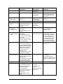
1
®
HP OmniBook 900
Service Manual
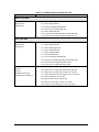
Notice
In a continuing effort to improve the quality of our products, technical and environmental information
in this document is subject to change without notice.
This manual and any examples contained herein are provided “as is” and are subject to change without
notice. Hewlett-Packard Company makes no warranty of any kind with regard to this manual,
including, but not limited to, the implied warranties of merchantability and fitness for a particular
purpose. Hewlett-Packard Co. shall not be liable for any errors or for incidental or consequential
damages in connection with the furnishing, performance, or use of this manual or the examples herein.
Consumer transactions in Australia and the United Kingdom: The above disclaimers and limitations
shall not apply to Consumer transactions in Australia and the United Kingdom and shall not affect the
statutory rights of Consumers.
© Copyright Hewlett-Packard Company 1999. All rights reserved. Reproduction, adaptation, or
translation of this manual is prohibited without prior written permission of Hewlett-Packard Company,
except as allowed under the copyright laws.
The programs that control this product are copyrighted and all rights are reserved. Reproduction,
adaptation, or translation of those programs without prior written permission of Hewlett-Packard Co.
is also prohibited.
Portions of the programs that control this product may also be copyrighted by Microsoft Corporation,
SystemSoft Corp., Crystal Semiconductor Corporation, Phoenix Technologies, Ltd., ATI
Technologies Inc., and NeoMagic, Inc. See the individual programs for additional copyright notices.
Microsoft, MS, MS-DOS, Windows and Windows NT are registered trademarks of Microsoft
Corporation. Pentium and the Intel Inside logo are U.S. registered trademarks and MMX is a U.S.
trademark of Intel Corporation. TrackPoint is a U.S. registered trademark of International Business
Machines.
All certifications may not be completed at product introduction. Check with your HP reseller for
certification status.
This equipment is subject to FCC rules. It will comply with the appropriate FCC rules before final
delivery to the buyer.
Hewlett-Packard Company
Mobile Computing Division
19310 Pruneridge Ave.
Cupertino, CA 95014, U.S.A.
Edition History
Edition 1 ........................ January 1999
Edition 2 .................... December 1999
ii
HP OmniBook 900
Contents
1. Product Information ..................................................................................................1-1
Features and Operation ................................................................................................................. 1-3
Turning the OmniBook On and Off....................................................................................... 1-4
Checking the Status of the OmniBook................................................................................... 1-5
Using Fn Hot Keys................................................................................................................. 1-6
Resetting the OmniBook........................................................................................................ 1-6
System Resources .................................................................................................................. 1-7
Specifications................................................................................................................................ 1-9
Internal Design............................................................................................................................ 1-13
2. Removal and Replacement ........................................................................................2-1
Removing the Battery (User-Replaceable) ................................................................................... 2-3
Removing a RAM Board (User-Replaceable) .............................................................................. 2-5
Removing the Hard Disk Drive (User-Replaceable) .................................................................... 2-6
Replacing Small Parts (User-Replaceable)................................................................................... 2-9
Removing the LCD Module (HP Authorized Service Providers Only)...................................... 2-10
Removing the Keyboard (HP Authorized Service Providers Only) ........................................... 2-12
Removing the CPU Module (HP Authorized Service Providers Only)...................................... 2-14
Removing the Display Assembly (HP Authorized Service Providers Only).............................. 2-16
Removing the Top Case (HP Authorized Service Providers Only)............................................ 2-18
Removing the Motherboard or Bottom Case (HP Authorized Service Providers Only) ............ 2-20
Removing the BIOS IC (HP Authorized Service Providers Only)............................................. 2-24
Removing Other Components (HP Authorized Service Providers Only)................................... 2-26
3. Troubleshooting and Diagnostics..............................................................................3-1
Troubleshooting............................................................................................................................ 3-2
Troubleshooting the Problem................................................................................................. 3-2
Verifying the Repair .............................................................................................................. 3-3
Suggestions for Troubleshooting ........................................................................................... 3-4
Diagnostic Tools......................................................................................................................... 3-12
OmniBook Diagnostic Program........................................................................................... 3-12
Power-On Self-Test ............................................................................................................. 3-18
Sycard PCCtest 450 CardBus Card (Optional).................................................................... 3-21
Desktop Management Interface (DMI)................................................................................ 3-22
BIOS Setup Utility............................................................................................................... 3-24
4. Replaceable Parts .......................................................................................................4-1
5. Reference Information ...............................................................................................5-1
Password Removal Policy ............................................................................................................ 5-1
Hewlett-Packard Display Quality Statement ................................................................................ 5-2
Obsolete Parts ............................................................................................................................... 5-5
HP OmniBook 900
iii
Figures
Figure 1-1. OmniBook - Front View ....................................................................................................1-3
Figure 1-2. OmniBook - Side View .....................................................................................................1-3
Figure 1-3. OmniBook - Rear View .....................................................................................................1-3
Figure 1-4. Replaceable Module Diagram .........................................................................................1-13
Figure 2-1. Removing the Battery ........................................................................................................2-3
Figure 2-2. Installing a Battery Panel...................................................................................................2-4
Figure 2-3. Removing a RAM Board ...................................................................................................2-6
Figure 2-4. Removing the Hard Disk Drive .........................................................................................2-7
Figure 2-5. Installing a Hard Drive in the Cover..................................................................................2-7
Figure 2-6. Removing the LCD Module ............................................................................................2-11
Figure 2-7. Removing the Keyboard ..................................................................................................2-13
Figure 2-8. Removing the CPU Module.............................................................................................2-15
Figure 2-9. Removing the Display Assembly.....................................................................................2-17
Figure 2-10. Removing the Top Case.................................................................................................2-19
Figure 2-11. Removing the Motherboard ...........................................................................................2-21
Figure 2-12. Installing PCMCIA Doors .............................................................................................2-23
Figure 2-13. Example of Serial Number Label ..................................................................................2-24
Figure 2-14. Removing the BIOS IC..................................................................................................2-25
Figure 3-1. Basic Troubleshooting Steps .............................................................................................3-2
Figure 3-2. OmniBook Diagnostic Screens — Basic and Advanced .................................................3-12
Figure 3-3. Serial and Parallel Loopback Connectors........................................................................3-14
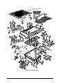
Figure 4-1. Exploded View ..................................................................................................................4-2
Figure 4-2. Display Components..........................................................................................................4-6
Tables
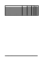
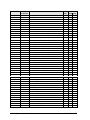
Table 1-1. OmniBook 900 Models.......................................................................................................1-1
Table 1-2. Product Comparisons ..........................................................................................................1-2
Table 1-3. Activating Power Modes.....................................................................................................1-4
Table 1-4. Main Status Lights (Motherboard)......................................................................................1-5
Table 1-5. Keyboard Status Lights (Motherboard)...............................................................................1-5
Table 1-6. Fn Hot Keys ........................................................................................................................1-6
Table 1-7. System Interrupts ................................................................................................................1-7
Table 1-8. System Memory ..................................................................................................................1-7
Table 1-9. System Input/Output Addresses (100-3FF).........................................................................1-8
Table 1-10. DMA Channels .................................................................................................................1-8
Table 1-11. OmniBook 900 Specifications ..........................................................................................1-9
Table 1-12. OmniBook 900 Accessories............................................................................................1-11
Table 1-13. Functional Structure........................................................................................................1-14
Table 2-1. Removal Cross-Reference...................................................................................................2-1
Table 2-2. Required Equipment ...........................................................................................................2-2
Table 2-3. Recommended Screw Torques............................................................................................2-2
Table 2-4. RAM Board Replacement Part Numbers............................................................................2-5
Table 2-5. Hard Disk Drive Replacement Part Numbers .....................................................................2-6
Table 2-6. Replacing Small Parts (User-Replaceable) .........................................................................2-9
Table 2-7. Display Component Compatibility....................................................................................2-10
Table 2-8. Removing Display Components .......................................................................................2-27
Table 3-1. Scope of Diagnostic Tools ..................................................................................................3-4
Table 3-2. Troubleshooting Suggestions..............................................................................................3-5
Table 3-3. OmniBook Diagnostic Error Codes ..................................................................................3-14
iv
HP OmniBook 900
Table 3-4. POST Terminal-Error Beep Codes .................................................................................. 3-18
Table 3-5. POST Messages ............................................................................................................... 3-18
Table 3-6. BIOS Setup Menus and Parameters ................................................................................. 3-24
Table 4-1. OmniBook Replaceable Parts ............................................................................................ 4-3
Table 4-2. Assembly-Component Breakdown..................................................................................... 4-7
Table 4-3. Accessory Replaceable Parts.............................................................................................. 4-7
Table 4-4. Part Number Reference ...................................................................................................... 4-9
Table 5-1. OmniBook 900 LCD Guidelines (TFT) ............................................................................. 5-3
Table 5-2. Obsolete Repair Parts......................................................................................................... 5-5
HP OmniBook 900
v
Introduction
This service manual provides reference information for the HP OmniBook 900. It is intended to be
used by HP-authorized service personnel in the installation, servicing, and repair of these products.
The manual is designed to be self-contained. It is intended that you can follow this manual without
having equipment available.
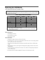
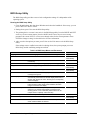
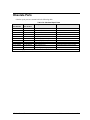
The following table lists additional places where you can get supplementary information about
OmniBook products.
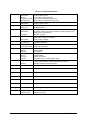
Sources of OmniBook Information
Source
HP External Web
HP US Reseller Web
Address or Number
http://www.hp.com/omnibook
(http://www.europe.hp.com/omnibook,
European mirror)
http://partner.americas.hp.com
HP Asia Pacific Channel
Support Centre for DPSP
Partners
America Online
http://www.hp.com.au
CompuServe
GO HP
Keyword: HP
HP Bulletin Board Service
HP Support Assist CD-ROM
Microsoft Web
vi
(800) 457-1762
(801) 431-1587
http://www.microsoft.com
Comments
No usage restriction.
Restricted to Authorized Resellers
only.
Restricted to DPSP Partners only.
Call (800) 827-6364 for membership
within the US.
Call (800) 524-3388 for membership
within the US.
Refer to the latest Product Support
Plan for non-US BBS numbers.
US and Canada.
Outside US and Canada.
Information and updates for Windows
operating systems.
HP OmniBook 900
1
Product Information
The HP OmniBook 900 provides desktop-quality performance and expandability in a highly portable
form. It uses high-performance component technologies that make it capable of serving as a desktop
computer that you can conveniently take anywhere.
Table 1-1. OmniBook 900 Models
OmniBook
Product *
F1711x
F1712x
F1760x
CPU **
Display
Hard Drive
Floppy Drive
Pentium II
300 MHz
Pentium II
366 MHz
Pentium II
400 MHz
12.1-inch
SVGA TFT
4 GB
(none)
6 GB
(F1707A)
1.44 MB
(F1472A)
F1765x
F1769xB
CD-ROM
Drive
None
Standard
RAM
32 MB
96 MB
(F1457A)
64 MB
Pentium III
450 MHz
B
Pentium III
13.3-inch
12 GB
F1770x
500 MHz
XGA TFT
(F1744B)
This table lists only base product configurations—custom configurations are not included.
*
For the products listed:
"x" suffix means
"N", "NT", “NV”, or “NG” for Windows NT 4.0 installed (marketing distinction only), or
"W", "WT", “WV”“WG”, or “WR” for Windows 95/98 installed (marketing distinction only).
** Intel Mobile Pentium II or Mobile Pentium III processor.
B
The OmniBook 900 Series has two classes of products with different internal designs, different software
B
drivers, and different BIOSes. Models marked with have “900 B” after the serial number and are called
900B in this manual—other OmniBook 900 models listed in this table are called 900† in this manual, and
they have no marking after the serial number.
HP OmniBook 900
Product Information
1-1
Table 1-2. Product Comparisons
OmniBook 900
Intel Pentium III (500
or 450 MHz), or
Pentium II (300 to 400
MHz).
64 or 32 MB RAM on
motherboard.
Expandable to
160 MB.
13.3-inch TFT XGA
display, or 12.1-inch
TFT SVGA display.
OmniBook 7150
Pentium II (300 MHz).
OmniBook 4150
OmniBook 2100
Pentium II (300 to 400 Pentium II (233 to 300
MHz).
MHz), or Pentium (233
or 200 MHz).
64 MB RAM in system
slot.
Expandable to
320 MB.
14.1-inch TFT XGA
display.
128 or 64 MB RAM in
slot.
Expandable to
256 MB.
13.3- or 14.1-inch TFT
XGA display.
Video
AGP video.
256-bit graphics
controller with 4 or
2.5 MB internal video
RAM.
Up to 16M colors
(XGA).
Zoomed Video
enabled.
Operating
System
Windows 95,
Windows 98, or
Windows NT 4.0
preinstalled.
DMI 2.0.
HP TopTools 3.0 to
4.5.
AGP video.
64-bit graphics
controller with 4 MB
external video RAM,
3D graphics
acceleration.
Up to 16M colors
(XGA).
Zoomed Video
enabled.
Windows 95,
Windows 98, or
Windows NT 4.0
preinstalled.
DMI 2.0.
HP TopTools 3.0.
AGP or PCI local bus
video.
256-bit graphics
controller with 8, 4, or
2.5 MB internal video
RAM.
Up to 16M colors
(XGA).
Zoomed Video
enabled.
Windows 95,
Windows 98, or
Windows NT 4.0
preinstalled.
DMI 2.0.
HP TopTools 3.0 to
4.5.
APM 1.2.
ACPI compliant.
APM 1.2.
ACPI compliant.
Processor *
Memory
Display
Desktop
Management
Interface
APM 1.2.
Power
Management ACPI compliant.
Power States On, Standby, Suspend,
Hibernate, Off.
*
32 MB RAM on
motherboard.
Expandable to 160,
192, or 288 MB.
13.3-inch TFT XGA
display, or 12.1-inch
TFT or DSTN SVGA
display.
PCI local bus video.
128-bit graphics
controller with 2 MB
internal video RAM.
Up to 64K colors
(XGA), 16M colors
(SVGA).
Zoomed Video
enabled.
Windows 95,
Windows 98, or
Windows NT 4.0
preinstalled.
DMI 2.0.
HP TopTools 2.6 or
3.0.
APM 1.2.
ACPI compliant.
On, Standby, Suspend, On, Standby, Suspend, On, Standby, Suspend,
Hibernate, Off.
Hibernate, Off.
Hibernate, Off.
Intel Mobile Pentium, Mobile Pentium II, or Mobile Pentium III processor.
This chapter describes
• Features and operation (below).
• Specifications (page 1-9).
• Internal design (page 1-13).
1-2
Product Information
HP OmniBook 900
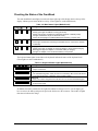
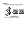
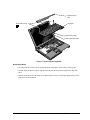
Features and Operation
The following three illustrations point out the main external features of the computer. They are
followed by highlights of the computer’s operation. For an internal, exploded view, see page 4-2.
Latch
Microphone
Keyboard status lights
Power button
Pointing stick
Touch pad
AC adapter socket
External module bay connector
Click buttons
(above and below
the touch pad)
PC Card slots
PC Card eject buttons
Figure 1-1. OmniBook - Front View
PS/2 port
Battery
System-off button
Speaker
Infrared port
Audio jacks
Main status lights
Hard disk drive
Figure 1-2. OmniBook - Side View
Kensington Serial
lock slot
port
Parallel
port
Video
out
USB
port
Docking
port
Kensington
lock slot
Figure 1-3. OmniBook - Rear View
HP OmniBook 900
Product Information
1-3
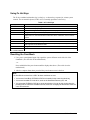
Turning the OmniBook On and Off
• On. Press the blue power button to turn on the OmniBook.
• Standby. The display turns off automatically if the computer is inactive for about 2 minutes.
• Suspend. Click Start, Suspend (Windows 95) or Start, Shut Down, Standby (Windows 98 or
2000), or press the blue power button briefly (about 1 second) to suspend activity when the
OmniBook is on. When you turn on the computer, it resumes your previous work session.
Closing the lid (for more than 2 seconds) also suspends the computer.
• Hibernate. Press Fn+F12. This is like Off, except that your current work session is first saved to
disk. When you turn on the computer, it reboots and restores your previous session.
• Off. Click Start, Shut Down. If the OmniBook does not respond, press and hold the blue power
button until the display shuts down. When you turn on the computer, it reboots. Unsaved data is
lost.
Table 1-3. Activating Power Modes
Power Mode
Standby
Reduced-power/stopped state. Display is off.
Everything is in a reduced-power state. Network
devices are maintained. Your current work session
continues at turn-on (any key or pointer action).
Suspend
Low-power/stopped state. Lower power state than
Standby. Everything is off or in a low-power state.
Network devices are off. Your previous work session
resumes at turn-on. For plug-and-play operating
systems, network connections resume at turn-on.
Hibernate
No-power/stopped state. Session is saved on the
hard disk. Everything is shut down. Computer
reboots at turn-on and restores previous session
and network connections (if plug-and-play).
Off
No-power/stopped state. Everything is shut down
(battery continues charging if ac adapter is
connected). Computer reboots at turn-on and
restores network connections.
1-4
Product Information
To Enter Mode
Press Fn+S (not Windows 98
or 2000)
–or–
allow time-out.
To Turn Back On
Press any key or move
a pointing device to
display the current
session ("Instant-On").
Press blue power button for
about 1 second
–or–
click Start, Shut Down,
Standby (Windows 98 or
2000)
–or–
click Start, Suspend (Windows
95)
–or–
allow time-out.
Press Fn+F12
–or–
allow time-out.
Press blue power
button to display the
current session
("Instant-On").
Click Start, Shut Down
–or–
Press and hold the blue power
button until the display shuts
down.
Press blue power
button to restart with a
new session.
Press blue power
button to restart and
restore the previous
session.
HP OmniBook 900
Checking the Status of the OmniBook
The main OmniBook status lights, located at the front-right edge of the display bezel at the top of the
display, indicate power status and drive activity. (These lights are on the motherboard.)
Table 1-4. Main Status Lights (Motherboard)
Meaning
Power mode
Steady green light: OmniBook is running (On mode).
Steady orange light: OmniBook is suspended (Suspend or Standby mode).
No light: OmniBook is off (Off or Hibernate mode).
Green and orange lights: OmniBook failed when resuming, requires reset.
Drive access
Green light: OmniBook is accessing the hard disk drive or a drive in the external
module bay.
Charging
Steady green light: AC adapter is connected, battery is full or stopped charging.
Blinking green light: AC adapter is connected, battery is charging.
No light: AC adapter is not connected or battery is not present.
The keyboard status lights, located above the keyboard, indicate the states of the keyboard locks.
(These lights are on the motherboard.)
Table 1-5. Keyboard Status Lights (Motherboard)
Meaning
Caps Lock
Caps Lock is active.
Keypad Lock
The embedded keypad is active (Fn+F8 or Fn held down). Num Lock must also be
on for the numeric keys—otherwise, cursor control is active.
Num Lock
Num Lock is active. Keypad Lock must also be on to use the embedded keypad.
Scroll Lock
Scroll Lock is active.
In addition, the battery module has five lights that indicate its charge level. To view the lights, you
have to remove the battery and press the pad on the back next to the connector. The number of lights
that turn on indicates the charge.
HP OmniBook 900
Product Information
1-5
Using Fn Hot Keys
The Fn key combined with another key is a hot key—a shortcut key sequence for various system
controls. For an external keyboard, CTRL+ALT is normally equivalent to the Fn key.
Table 1-6. Fn Hot Keys
Hot Key
Fn + F1
Fn + F2
Fn + F5
Fn + F7
Fn + F8
Fn + F12
Fn + R
Fn + S
Fn + ScrLk
Fn + UP ARROW
Fn + DOWN ARROW
Effect
Decreases the display’s brightness.
Increases the display’s brightness.
Switches among the built-in display, an external display, and simultaneous displays.
Toggles audio output on and off (mute).
Toggles the embedded keypad on and off. Does not affect an external keyboard. If
Num Lock is on, then the numeric functions are active—otherwise, cursor control is
active.
Enters Hibernate mode.
Enters Suspend mode. Not supported under Windows 2000.
Enters Standby mode (Windows 95, Windows NT) or Suspend mode (Windows 98).
Not supported under Windows 2000.
Toggles Scroll Lock on and off.
Increases and decreases the sound volume.
Resetting the OmniBook
1. Use a pen or a straightened paper clip to push the system-off button on the left side of the
OmniBook. (The switch is on the motherboard.)
–or–
Press and hold the blue power button until the display shuts down. (The switch is on the
motherboard.)
2. After the computer shuts down, press the blue power button to turn it back on.
Note
The OmniBook can boot from a CD if all these conditions are true:
• You have an OmniBook CD-ROM or DVD drive installed in the external module bay,
• You have a bootable CD in the drive, such as the OmniBook Recovery CD, and
• You select the CD-ROM or DVD drive as the boot device. You can do this during reboot by
pressing ESC to cancel the OmniBook screen, then ESC to display the boot-device menu for
a one-time selection.
1-6
Product Information
HP OmniBook 900
System Resources
The tables in this section show typical resource usage as set up by the OmniBook BIOS. Plug-andplay operating systems, drivers, and BIOS Setup settings may change some of the entries.
To see other, non-default possibilities, use the BIOS Setup utility (see page 3-24), which lists port and
audio device configurations in the System Devices menu.
Table 1-7. System Interrupts
0
1
2
3
4
5
6
7
8
9
10
11
12
13
14
15
†
System timer
Keyboard
Cascade IRQ 9
Free (or COM2 infrared port, if enabled)
COM1 (serial port)
Audio
Floppy drive
LPT1 (ECP parallel port)
Real-time clock
Free (OmniBook 900B)
Video (OmniBook 900†)
USB and CardBus - assigned by Windows driver
Video Controller (OmniBook 900B)
Free
Pointing device
Numeric data processor
Internal hard disk (primary IDE controller)
Internal CD-ROM drive (secondary IDE controller)
Models called 900† in this manual have no marking in the serial number,
whereas models called 900B have 900 B after the serial number.
Table 1-8. System Memory
00000 - 9FFFF
System memory
A0000 - BFFFF
Video
C0000 - CBFFF
Video BIOS (OmniBook 900†)
C0000 - CFFFF
Video BIOS (OmniBook 900B)
CC000 - DBFFF* Free** (OmniBook 900†)
D0000 - DBFFF*
Free** (OmniBook 900B)
DC000*- FFFFF
System BIOS
* Approximate boundary.
** Valid uses for memory addresses CC000-DBFFF or D0000-DBFFF:
Upper memory blocks (UMBs).
PC card memory windows.
† Models called 900† in this manual have no marking in the serial number,
whereas models called 900B have 900 B after the serial number.
HP OmniBook 900
Product Information
1-7
Table 1-9. System Input/Output Addresses (100-3FF)
120-127
Audio (OmniBook 900† only)
170-177
Internal CD-ROM drive (secondary IDE controller)
1F0-1F7
Internal hard disk (primary IDE controller)
220-22F
Audio
376
Internal CD-ROM drive (secondary IDE controller)
378-37F
LPT1 (printer port)
388-38B
Audio
3B0-3BB
Video adapter
3C0-3DF
Video adapter
3E0-3E1
PCMCIA controller
3F0-3F5
Floppy controller
3F6
Internal hard disk (primary IDE controller)
3F7
Floppy controller
3F8-3FF
COM1 (serial port)
† Models called 900† in this manual have no marking in the serial number,
whereas models called 900B have 900 B after the serial number.
Table 1-10. DMA Channels
0
1
2
3
4
5
6
7
†
1-8
Sound record (OmniBook 900† only)
Free (OmniBook 900B only)
Sound playback
Floppy drive
LPT1 (ECP parallel port)
Cascade
Free
Free
Free
Models called 900† in this manual have no marking in the serial number,
whereas models called 900B have 900 B after the serial number.
Product Information
HP OmniBook 900
Specifications
The following tables list descriptions for the OmniBook and its accessories.
Table 1-11. OmniBook 900 Specifications
Physical Attributes
Processor and
Bus Architecture
Graphics
Power
Mass Storage
RAM
Audio System
Keyboard and
Pointing Device
HP OmniBook 900
Models with 12-inch display
Notebook size: 11.8 x 8.8 x 1.26 in (30.0 x 22.5 x 3.2 cm).
Notebook weight: 4 lb (1.8 kg).
Models with 13-inch display
Notebook size: 11.9 x 9.3 x 1.4 in (30.4 x 23.7 x 3.5 cm).
Notebook weight: 4.3 lb (1.9 kg).
500-MHz or 450-MHz Intel Mobile Pentium III processor, or
|400-MHz, 366-MHz or 300-MHz Intel Mobile Pentium II Performance Enhanced (PE)
processor.
1.6-V core, 2.5-V external, low-power processor.
32-KB (16-KB instruction, 16-KB data) L1 cache.
256-KB four-way set-associative L2 cache.
32-bit PCI bus.
13.3-inch diagonal XGA (1024 x 768) TFT display or 12.1-inch diagonal SVGA (800
x 600) TFT display.
Zoomed Video support for lower PC Card slot.
OmniBook 900†:
256-bit NeoMagic MagicGraph graphics accelerator with 2.5-MB video RAM, 1x AGP
graphics capability.
OmniBook 900B:
ATI Mobility-M graphics accelerator with 4-MB video RAM, 2x AGP graphics
capability.
Rechargeable 6-cell lithium ion battery with LED charge-level gauge (11.1 Vdc).
Battery life: up to 3-4 hours typical (varies with type of usage and model).
Fast battery recharge: 80% in 1 hour, 100% in 1.5-2 hours.
Low-battery warning.
Suspend/resume capability.
60-watt ac adapter: 100 to 240 Vac (50 to 60 Hz) input, 19 Vdc, 3.16 A output.
12-GB, 6-GB or 4-GB removable hard drive.
1.44-MB floppy drive module for use in external module bay.
Optional
CD-ROM drive module.
LS-120 SuperDisk drive module.
DVD drive module.
OmniBook 900†:
32-MB RAM built in. One slot for RAM expansion up to 160 MB.
66-MHz RAM bus.
OmniBook 900B:
64-MB RAM built in. One slot for RAM expansion up to 192 MB.
100-MHz RAM bus.
16-bit Sound Blaster Pro-compatible stereo sound.
Built-in speaker.
3D-enhanced PCI bus audio with Zoomed Video support.
Built-in microphone.
Line-in, headphone-out, and microphone-in.
87/88-key touch-type QWERTY keyboard with 101/102 key emulation.
Embedded numeric keypad.
12 function (Fn) keys.
Two pointing devices: pointing stick (TrackPoint technology licensed from IBM) and
touch pad.
Product Information
1-9
FDD/IDE interface for external module bay.
Universal serial bus (USB).
9-pin, 115,200-bps serial (16550 UART).
25-pin bi-directional ECP/EPP parallel.
Video-out (Resolution: up to 1280×1024×256 colors, or up to 1600×1200×64K colors
for Omnibook 900B. Refresh rate: 60 to 85 Hz.)
PS/2 keyboard/mouse.
4-Mbps IrDA-compliant infrared port.
One Type III or two Type II 16-/32-bit PC Card slots (3.3- and 5-V support).
Expandability
CardBus enabled.
External plug-in module bay for accessory modules.
Optional port replicator, mini dock, and docking system.
Microsoft Windows 95/Windows 98, or Windows NT 4.0.
Software
Windows 95/Windows 98-compatible Plug-and-Play.
Windows NT 4.0 and PC Card Plug-and-Play.
Advanced Power Management (APM).
DMI with HP TopTools.
Adobe Acrobat Reader.
Agaté Tioman for HP (Hot Swap).
DiagTools.
VirusScan.
Online Reference Guide.
OmniBook Recovery CD included.
Centralized worldwide BIOS and driver update service
User and administrator passwords.
Security Features
System, hard drive, and docking passwords.
PC identification displayed at boot.
DMI-accessible electronic serial number.
Kensington MicroSaver lock slot.
Operating temperature: 5 to 35 °C (41 to 95 °F).
Environmental Limits
Operating humidity: 20 to 90 percent RH (5 to 35 °C).
Storage temperature: –20 to 50 °C (–4 to 122 °F).
Major ICs
OmniBook 900†:
CPU: Intel Mobile Pentium II Performance Enhanced (PE) processor.
South Bridge: PIIX4E.
Video: NeoMagic MagicGraph NM2200 (NMG5).
Audio: NeoMagic MagicGraph NM2200 (NMG5) and NeoMagic Audio NMA2.
CardBus: TI PCI 1225.
Keyboard controller: National PC87570.
Super I/O: SMC 769.
OmniBook 900B:
CPU: Intel Mobile Pentium III processor.
South Bridge: PIIX4M.
Video: ATI Mobility-M.
Audio: ESS ES1978 Maestro-2E and ESS ES1921.
CardBus: TI PCI 1225.
Keyboard controller: National PC87570.
Super I/O: SMC 869.
† Models called 900† in this manual have no marking in the serial number, whereas models called 900B
have 900 B after the serial number.
Input/Output
1-10
Product Information
HP OmniBook 900
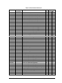
Table 1-12. OmniBook 900 Accessories
Accessory
Description
OmniBook
900B
900†
4150
2100/7100
32-MB SDRAM (66 MHz) expansion module
•
•
•
64-MB SDRAM (66 MHz) expansion module
•
•
•
•
•
•
•
•
•
•
•
•
•
•
•
•
•
Memory
F1456A
F1457A
F1622A
128-MB SDRAM (66 MHz) expansion module
F1456B
32-MB SDRAM (100 MHz) expansion module
•
F1457B
64-MB SDRAM (100 MHz) expansion module
F1622B
128-MB SDRAM (100 MHz) expansion module
Hard Drives
F1707A
Compatibility
•
6-GB internal hard disk drive
12-GB internal hard disk drive
•
DVD drive module (with DVD player card)
•
•
•
F1470A
LS-120 SuperDisk drive module
•
•
•
F1472A
Floppy drive module
•
•
•
F1473A
Floppy drive cable for external use
•
•
•
F1474A
24X CD-ROM drive module
•
•
•
F1653A/B
DVD drive module
•
•
•
F1704A
External module bay
•
•
F1746A/B
10/12-GB second hard drive module
•
•
F1744B
Modules
F1465A
Power Options
F1454A
60-watt ac adapter
•
•
•
•
F1455A
75-watt auto/airline power adapter
•
•
•
•
F1705A
Lithium-ion battery
•
•
F1706A
Battery charger (external)
•
•
8120-6312
8120-6313
8120-6314
8120-6316
8120-6317
8120-8367
8120-8373
Replacement power cord (Australia)
Replacement power cord (U.S., Canada, Taiwan)
Replacement power cord (Europe)
Replacement power cord (Japan)
Replacement power cord (India, South Africa)
Replacement power cord (Argentina)
Replacement power cord (People’s Republic of
China)
Replacement power cord (Chile)
Replacement power cord (Hong Kong, Singapore,
U.K.)
•
•
•
•
PS/2 Y adapter
•
•
•
•
•
•
•
•
F1625A
10/100-Mbps Ethernet + 56-Kbps modem PC
Card by Xircom
56-Kbps global modem PC Card by Xircom
•
•
•
•
F1626A
10/100-Mbps Ethernet PC Card by 3Com
•
•
•
•
F1627A
56-Kbps US modem PC Card by Xircom
•
•
•
•
F1643A
Realport 10/100-Mbps Ethernet + 56-Kbps
modem PC Card by Xircom
•
•
•
•
8120-8452
8120-8699
Adapters
F1469A
PC Cards
F1623A
HP OmniBook 900
Product Information
1-11
Accessory
Description
OmniBook
Compatibility
900B
900†
4150
F1761B
MPEG DVD decoder PC Card
•
•
•
TCM3C589
10-Mbps Ethernet PC Card by 3Com
•
•
•
•
Docks
F1451A
2100/7100
Port replicator (tray: page 4-7)
•
•
•
•
F1452A
Mini dock (tray: page 4-7)
•
•
•
•
F1453A
Monitor stand (short) for F1451A and F1452A
•
•
•
•
F1468A
Docking module bay adapter
•
•
•
Docking system and monitor stand (tall) (tray:
•
•
•
•
page 4-7)
Models called 900† in this manual have no marking in the serial number, whereas models called 900B
have 900 B after the serial number.
F1477A
†
1-12
Product Information
HP OmniBook 900
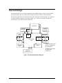
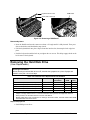
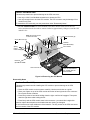
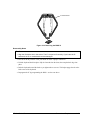
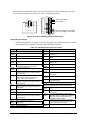
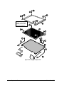
Internal Design
The motherboard PCA is the central component of the OmniBook design. It plays a role in virtually
all system functions. The CPU module and most other subsystems connect to the motherboard.
The following figure shows the connections among the replaceable electrical modules. As a substitute
for a functional block diagram, see the table on page 1-14—it lists the roles that the replaceable
modules play in each of the functional subsystems.
LCD Module
Top Case
(microphone) Touch
Pad
CPU
Module
RAM
Board
External
Module Bay
BIOS
IC
Motherboard
PCA
PCMCIA
Socket
PCMCIA
Cards
Speaker
Fan
Hard Disk
Drive
The power switch and lid
switch are contained on
the motherboard.
Battery
All external connections
are made to the
motherboard.
Keyboard
(pointing stick)
Figure 1-4. Replaceable Module Diagram
HP OmniBook 900
Product Information
1-13
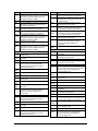
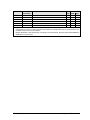
Table 1-13. Functional Structure
CPU module
Motherboard
BIOS IC
Floppy disk module
Hard disk drive
CPU module
Motherboard
Main processor.
Primary system circuitry.
Code for basic system functions.
First source of disk-based startup code.
Second source of disk-based startup code.
Main processor, numeric data processor, L1 and L2 cache.
Primary system circuitry.
Memory
Motherboard
RAM board
First 32 MB of RAM, video RAM.
Changeable RAM.
Power
Battery
Motherboard
LCD module
Motherboard
Hard disk drive
Power storage.
AC adapter socket, power switch, lid switch, system-off switch, power
supply, power control circuitry.
AC-to-DC converter.
Display/graphics controller, PCMCIA/zoomed video controller, video
RAM, power converter for backlight.
Display output, backlight.
Hard disk controller.
Hard disk mechanism.
Floppy drive
Motherboard
Floppy disk module
Floppy disk controller.
Floppy disk mechanism.
Keyboard
Audio
Motherboard
BIOS IC
Keyboard
Motherboard
BIOS IC
Keyboard
Top case
Motherboard
Status
Speaker
Motherboard
Keyboard controller.
Keyboard BIOS.
Key switches.
Keyboard controller, pointing stick controller (PS/2 output).
Keyboard BIOS.
Pointing stick sensor.
Touch pad sensor, controller (PS/2 output).
Audio controller, audio decoder, speaker amplifier, headphone amplifier,
zoomed video controller, external audio jacks, microphone.
Speaker (mixed left and right channels).
Keyboard controller, main LEDs, keyboard LEDs.
Serial
Motherboard
I/O controller, serial connector.
Parallel
Motherboard
I/O controller, parallel connector.
Infrared
Motherboard
I/O controller, infrared transmitter/receiver.
PS/2 port
Motherboard
Keyboard controller, PS/2 processor, PS/2 connector.
USB
Motherboard
Bus controller (South Bridge), USB connector.
Docking port
Motherboard
Docking logic, docking connector.
PCMCIA
Motherboard
PCMCIA socket
PCMCIA controller.
PCMCIA connectors.
Bootup
Processor
AC adapter
Motherboard
Display
Hard disk
Pointer
1-14
Product Information
HP OmniBook 900
2
Removal and Replacement
This chapter tells you how to remove and replace the following components and assemblies. The ones
marked by • are user-replaceable.
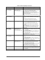
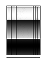
Table 2-1. Removal Cross-Reference
• Battery (page 2-3)
Bezel, display (page 2-27)
• Bumper, display (page 2-9)
Cable, display flex (page 2-27)
Cable, display power (page 2-27)
• Cap, pointing stick (page 2-9)
Case, bottom (page 2-20)
Case, display (page 2-27)
• Case, HDD kit (page 2-6)
Case, top (page 2-18)
• Cover, display screw (page 2-9)
• Cover, hinge (page 2-9)
• Cover, keyboard screw (page 2-9)
CPU module (page 2-14)
• Door, HDD (page 2-9)
Door, module bay connector (table starting on
page 2-28)
• Drive, hard disk (page 2-6)
Fan (table starting on page 2-28)
• Foot (page 2-9)
Heatsink (table starting on page 2-28)
Hinge, display (page 2-27)
IC, BIOS (page 2-24)
Insulator, bottom case (table starting on
page 2-28)
Keyboard (page 2-12)
Latch, display (page 2-27)
LCD module (page 2-10)
Lens, infrared (table starting on page 2-28)
Overlay, serial number (page 2-23)
Pads, thermal (table starting on page 2-28)
PCA, motherboard (page 2-20)
Socket, PCMCIA (table starting on page 2-28)
Speaker (table starting on page 2-28)
Support, hinge left (table starting on page 2-28)
Support, hinge right (table starting on
page 2-28)
Support, touch-pad (page 2-28)
Touch pad (page 2-28)
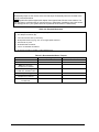
Caution
Always provide proper grounding when performing repairs. Without proper
grounding, an electrostatic discharge may damage the OmniBook and its
components.
HP OmniBook 900
Removal and Replacement
2-1
Notes
Reassembly steps are the reverse of the removal steps. Reassembly notes are included at the
end of each section below.
Symbols like this throughout this chapter show approximate full-size screw outlines. You
can use them to verify the sizes of screws before you install them. Installing a wrong-size screw
can damage the unit. (The symbol at the left represents an M2.5×5mm T-head screw.)
Table 2-2. Required Equipment
•
•
•
•
•
•
•
•
Small Phillips screwdriver (#1), preferably magnetized.
Fine Phillips screwdriver (#0).
4-mm thin-wall hex driver (or 5/32 inch).
Small plastic blade for prying, such as an angled plastic tweezers.
Pointed knife or probe.
Small flat-blade screwdriver.
4.0-4.5 mm flat-blade screwdriver.
IC (PLCC) removal tool (similar to OK Industries EX-5).
Table 2-3. Recommended Screw Torques
Screw Thread Size
M1.4
M2
M2.5 (4–5 mm long)
except those in next line
M2.5 (4–5 mm long)
for HDD case, PCMCIA socket
M2.5 (8 mm long)
M3
except those in next line
M3
for HDD case
2-2
Removal and Replacement
Torque (kgf•cm)
0.9 – 1.2
1.5 – 2.0
3.0 – 3.5
Torque (lbf•in)
0.8 – 1.0
1.3 – 1.7
2.6 – 3.0
2.0 – 2.5
1.7 – 2.2
3.5 – 4.0
4.0 – 4.5
3.0 – 3.4
3.4 – 3.9
2.0 – 2.5
1.7 – 2.2
HP OmniBook 900
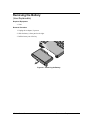
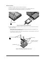
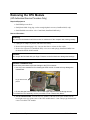
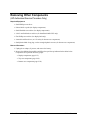
Removing the Battery
(User-Replaceable)
Required Equipment
• None.
Removal Procedure
1. Unplug the ac adapter, if present.
2. Slide the battery’s front panel to the right.
3. Pull the battery out of the bay.
Figure 2-1. Removing the Battery
HP OmniBook 900
Removal and Replacement
2-3
Reassembly Notes
• If you are installing a new battery, first snap the correct panel onto the front of the battery. For a
12-inch display, use the flat battery panel—for a 13-inch display, use the curved battery panel. To
remove a panel, slide it open, then twist the upper edge of the panel off the battery.
Figure 2-2. Installing a Battery Panel
• Make sure the front panel of the battery is open before inserting the battery.
2-4
Removal and Replacement
HP OmniBook 900
Removing a RAM Board
(User-Replaceable)
Table 2-4. RAM Board Replacement Part Numbers
Description
Part Number
Exchange
Part Number
OmniBook
900B
900†
RAM board, 32MB PC100 SODIMM
1818-7950
•
•
RAM board, 64MB PC100 SODIMM
1818-7951
F1660-69103
•
•
RAM board, 128MB PC100 SODIMM
1818-7952
F1660-69104
•
•
Caution
Handle the RAM board only by its edges and provide proper grounding. Otherwise, you may
damage the board due to electrostatic discharge.
Required Equipment
• Small Phillips screwdriver.
Removal Procedure
1. Unplug the ac adapter, if present, and remove the battery.
2. Put your finger above the F8 key and slide the keyboard-screw cover to the left about 3 mm
(1/8 inch)—then lift off the cover.
3. Remove the two screws holding the keyboard above the F1 and HOME keys. If your screwdriver
has a fat shaft, protect or remove the right hinge cover.
4. Lift up the keyboard tab above the F1 key about 10 mm (1/2 inch), then free the snap at the center
of the back edge.
5. Slide the keyboard toward the display about 5 mm (1/4 inch), then fold the keyboard forward onto
the front of the top case.
Warning
Do not touch the heatsink until it has cooled. It could be hot if the computer was running recently.
6. Release the two latches at the sides of the RAM board, so the free edge of the board pops up.
7. Pull the board out of the connector.
HP OmniBook 900
Removal and Replacement
2-5
Keyboard-screw cover
RAM board
Screw, M2.5×4mm (2)
Figure 2-3. Removing a RAM Board
Reassembly Notes
• Insert the RAM board into the connector at about a 30° angle until it is fully inserted. Then press
down at both sides until both latches snap closed.
• Fold the keyboard back into place. Slip its front tabs into the slots, then snap the back edge into
place.
• Push the keyboard toward the back as you tighten the two screws. This helps engage the tab at the
back-center of the keyboard.
Removing the Hard Disk Drive
(User-Replaceable)
Exchange Information
When returning a bad hard disk drive to HP, describe the symptoms on a piece of paper and
attach it to the part—do not use tape.
Table 2-5. Hard Disk Drive Replacement Part Numbers
Description
Part Number
Exchange
OmniBook
Part Number
900B
900†
Drive, hard disk (4.3GB, 9.5mm, IBM) *
0950-3409
F1711-69100
•
Drive, hard disk (4.3GB, 8.45mm, Toshiba)
0950-3410
F1386-69102
•
Drive, hard disk (6.0GB, 9.5mm, IBM) *
0950-3710
F1711-69106
•
Drive, hard disk (6.4GB, 9.5mm, IBM) *
0950-3442
F1711-69101
•
Drive, hard disk (12GB, 9.5mm, IBM) *
0950-3711
F1660-69105
•
*
These hard drives are the preferred drives at the time of publication. Drives shipped in units are
subject to change without notice. For current information about preferred and approved drives for
these products, see the latest version of service note HDD-01.
† Models called 900† in this manual have no marking in the serial number, whereas models called 900B
have 900 B after the serial number.
Required Equipment
• Small Phillips screwdriver.
2-6
Removal and Replacement
HP OmniBook 900
Removal Procedure
1. Unplug the ac adapter, if present, and remove the battery.
2. Turn the unit bottom side up and remove the hard drive screw from the bottom case.
3. Open the hard drive door, then pull out the hard drive by its plastic tab.
Screw, M2.5×5mm
Figure 2-4. Removing the Hard Disk Drive
4. If you are installing a new hard drive that does not have a cover, you can remove the cover parts
from the old hard drive:
• Remove the two screws from the case, then lift the plastic tab and remove the plastic cover
and metal shield from the hard disk drive.
• Carefully pry the connector off the end of the hard disk drive. Work alternately at each end so
that the connector slides off evenly.
Screw, M3×4mm
HDD cover kit
Small tabs on connector
face down in this view.
Hard disk drive
Figure 2-5. Installing a Hard Drive in the Cover
HP OmniBook 900
Removal and Replacement
2-7
Reassembly Notes
Caution
Do not cover the vent hole in the top surface of the hard drive. If you cover the hole, the hard drive
could fail prematurely.
• The small plastic tabs on the connector face the top of the drive, and the metal shield fits behind
the tabs.
Important
• If you are installing a new hard drive, create a Hibernate partition on the drive before loading
any software—see the steps below.
Note
For an OmniBook 900 with a 12-inch display and serial number before TW92500000, if the hard
disk drive has been damaged by excessive pressure, check whether you must replace additional
parts:
• If the bottom case has a large blue pad that covers the bottom of the hard disk slot, and if the
hard disk slot has a metal bracket across the top of the slot, replace just the hard disk.
• If the bottom case has such a pad in the hard disk slot, but there is no metal bracket across
the top of the slot, you should also replace the top case and install a HDD bracket above the
hard disk slot.
• If the bottom case does not have such a pad in the hard disk slot, it is an old bottom case,
and you should also replace the top case, bottom case, and install a HDD bracket above the
hard disk slot. (Service note 900-14.)
Creating a Hibernate Partition
1. Connect an external module bay and CD-ROM drive to the OmniBook.
If you do not have an OmniBook CD-ROM module or external module bay, you must attach
another type of CD-ROM drive.
2. Plug in the ac adapter.
3. Insert the Recovery CD in the CD-ROM drive.
4. Shut down and restart the computer—when you see the HP logo, press ESC two times.
5. Select the CD-ROM drive as the boot device.
6. When the Recovery CD dialog box appears, follow the displayed instructions. Accept the
recommended partition size. If you install the factory software, the recovery process can take up
to 10 minutes.
If you want to create the Hibernate partition without installing the factory software, click
Advanced and select the option to not install the operating system. If you intend to install
Windows NT, you should choose the FAT16 option or the Hibernate-only option.
Note: If, instead, you see an MS-DOS menu of options, select “Recover...” to create the
Hibernate partition and install the factory software, which can take up to 60 minutes. Or select
“Create Hibernate Partition” to not install the software. Accept the recommended partition size.
7. When prompted to reboot the computer, press CTRL+ALT+DEL and follow any displayed
instructions.
2-8
Removal and Replacement
HP OmniBook 900
Replacing Small Parts
(User-Replaceable)
The following small parts are user-replaceable.
Table 2-6. Replacing Small Parts (User-Replaceable)
Part
Battery panel
Bumper, display
(upper)
Cap, pointing stick
Cover, display screw
(lower)
Cover, hinge
Cover, keyboard
screw
Door, hard disk
Foot
HP OmniBook 900
Replacement Procedure
Remove the battery, then twist the upper edge of the panel off the battery.
Insert a small flat-blade screwdriver under the bumper and pry it loose. To replace,
firmly press the adhesive side of the bumper into the recess.
Pull the cap off the pointing stick.
Insert a small flat-blade screwdriver under the cover and pry it loose. To replace,
firmly press the adhesive side of the cover into the recess.
Put your finger above the F8 key and slide the keyboard-screw cover to the left about
3 mm (1/8 inch)—then lift off the cover. Open the display fully. Push in at the bottomfront of the cover to unsnap it from the top case.
Put your finger above the F8 key and slide the keyboard-screw cover to the left about
3 mm (1/8 inch)—then lift off the cover.
Open the door about 45° and flex the door until one side tab releases.
Insert a small flat-blade screwdriver under the foot and pry it loose. To replace, firmly
press the adhesive side of the foot into the recess.
Removal and Replacement
2-9
Removing the LCD Module
(HP Authorized Service Providers Only)
Exchange Information
When returning a bad LCD module to HP, describe the symptoms on a piece of paper and attach
it to the part—do not use tape.
Table 2-7. Display Component Compatibility
LCD Type*
OmniBook Model
12" IBM
12" Mitsubishi
900†/900B
900†/900B
F1711-60915
Bezel, display
Cable, LCD flex
F1711-60918
F1711-60978
F1770-60910
F1770-60912
F1711-60971
F1770-60907
F1711-60979
Latch, display
F1770-60901
F1770-60902
Hinge, cover
F1711-60938
Hinge, display (pair)
LCD Module
F1770-60923
F1711-60919
Cable, power
Case, display
F1769-60913
13" LG
13" Unipac
900B
900B
F1770-60906
F1711-69039
Support, left hinge
F1711-69072
F1711-60910
F1770-60908
F1770-69021
F1770-69020
F1770-60914
F1711-60911
F1770-60915
Support, right hinge
*
To identify the type of LCD module, see the marking printed on the LCD flex cable where it plugs into the
base—it may be on the top or bottom of the cable.
†
Models called 900† in this manual have no marking in the serial number, whereas models called 900B
have 900 B after the serial number.
Required Equipment
• Small Phillips screwdriver.
• Small flat-blade screwdriver.
• Pointed knife or probe.
Removal Procedure
1. Unplug the ac adapter, if present, and remove the battery.
2. On the display bezel, remove the two upper bumpers and two lower screw covers (using a pointed
knife or probe), then remove the four screws.
3. Along the top of the display, pull the bezel upward, toward the edge of the case, until the snaps
release.
4. Starting at the top corners, repeat along the left and right sides, pulling outward to release the left
and right edges.
5. Lift the top of the bezel away from the case about 7 cm (3 inches). The snaps along the bottom of
the bezel should release.
6. On the edge of the LCD module, unplug the LCD power wires from the power cable.
2-10
Removal and Replacement
HP OmniBook 900
7. For a 12-inch display, remove the LCD module.
a.
Remove the four screws holding the LCD module.
b.
Lift up the right edge of the LCD module about 90°.
c.
Using a small flat-blade screwdriver, insert the tip under the narrow end of the flex cable
connector—not the wide end—and twist the screwdriver to release the connector from the
LCD module.
8. For a 13-inch display, remove the LCD module.
a.
Close, but don’t latch the display; then lift off the display case.
b.
Loosen and then pull the flex cable out of the connector.
c.
Remove four screws, two each, on the right and left edges of the LCD module.
Bumper (oval)
Screw cover
Screw, M2.5×5mm
Screw, M3×4mm
Bezel
LCD module
LCD flex cable
Display case
Note: 12-inch display
shown. For a 13-inch
display, the flex cable
and mountings differ.
Power cable
Figure 2-6. Removing the LCD Module
HP OmniBook 900
Removal and Replacement
2-11
Reassembly Notes
• For the 12-inch display, make sure the LCD module and flex cable have small foam pads present
to ensure good connections:
Two pads on the back of the LCD module on the internal connections near the top-left and
bottom-left corners. If a pad is missing, replace the LCD module.
One pad on the LCD flex cable behind the connector that plugs into the LCD module. If the
pad is missing, replace the flex cable.
• For the 13-inch display, make sure the power wire is return to its original position. Where the
wire passes around the hinge cover opening, it tucks behind the LCD module.
Removing the Keyboard
(HP Authorized Service Providers Only)
Required Equipment
• Small Phillips screwdriver.
• Probe or tweezers.
Removal Procedure
1. Unplug the ac adapter, if present, and remove the battery.
2. Put your finger above the F8 key and slide the keyboard-screw cover to the left about 3 mm
(1/8 inch)—then lift off the cover.
3. Remove the two screws holding the keyboard above the F1 and HOME keys. If your screwdriver
has a fat shaft, protect or remove the right hinge cover.
4. Lift up the keyboard tab above the F1 key about 10 mm (1/2 inch). If necessary, free the snap at
the center of the back edge near the F8 key.
5. Slide the keyboard toward the display about 5 mm (1/4 inch), then fold the keyboard forward onto
the front of the top case.
Warning
Do not touch the heatsink until it has cooled. It could be hot if the computer was running recently.
6. Release the pointing stick flex cable from the motherboard.
7. Release the keyboard flex cable from the motherboard, then remove the keyboard.
2-12
Removal and Replacement
HP OmniBook 900
Keyboard-screw
cover
Screw, M2.5×4mm
Keyboard
Keyboard flex cable
Pointing stick flex cable
Figure 2-7. Removing the Keyboard
Reassembly Notes
• To connect the flex cables, lay the keyboard upside-down on the front section of the top case.
• Fold the keyboard back into place. Slip its front tabs into the slots, then snap the back edge into
place.
• Push the keyboard toward the back as you tighten the two screws. This helps engage the tab at the
back-center of the keyboard.
HP OmniBook 900
Removal and Replacement
2-13
Removing the CPU Module
(HP Authorized Service Providers Only)
Required Equipment
• Small Phillips screwdriver.
• Small plastic blade for prying, such as an angled plastic tweezers (OmniBook 900† only).
• Small flat-blade screwdriver: 4.0-4.5 mm blade (OmniBook 900B only).
Removal Procedure
Warning
Do not touch the heatsink until it has cooled. It could be hot if the computer was running recently.
1. Unplug the ac adapter, if present, and remove the battery.
2. Remove the keyboard (page 2-12)—but you don’t have to release the flex cables.
3. Remove the eight screws (OmniBook 900†) or six screws and springs (OmniBook 900B) from
the heatsink and lift off the heatsink.
Caution
Do not spin the fan blade with your finger. Pressure on the fan blade can damage the bearings.
Caution: OmniBook 900†
Follow these precautions to prevent damage to the CPU connector:
• Use only a non-metallic tool for releasing the CPU module. A metal tool may damage the
motherboard.
Pry up at these two
places.
• Do not raise the front end or the CPU module higher than the back end during removal.
To reinstall the CPU assembly, see the precautions under “Reassembly Notes.”
4. For an OmniBook 900†, to release the CPU module, at the side of the CPU module near the
back-right corner, pry up the corner of the CPU module about 1-2 mm. Then pry up the back-left
corner. Lift off the CPU module.
2-14
Removal and Replacement
HP OmniBook 900
Caution: OmniBook 900B
Follow these precautions to prevent damage to the CPU connector:
• Use only a 4.0-4.5 mm flat-blade screwdriver to release the CPU.
• Use only enough force to lock the CPU module. The CPU connector may be damaged if too
much force is used.
To reinstall the CPU assembly, see the precautions under “Reassembly Notes.”
5. For the OmniBook 900B, insert the flat-blade screwdriver into the release slot of the CPU
socket, and then turn the screwdriver counter-clockwise (approximately 10 degrees) until the CPU
module is free.
Note: Do not put screws
in these two holes.
Screw, M2×5mm (8)
Screw, M2×5mm (6)
Heatsink
(OmniBook 900†)
Spring
(insert
under heatpipe)
CPU module
Heatsink
(OmniBook 900B)
CPU connector
Note: OmniBook 900† CPU
module and motherboard
shown. Details differ for
OmniBook 900B.
Figure 2-8. Removing the CPU Module
Reassembly Notes
Caution: OmniBook 900†
Follow these precautions while installing the CPU module to prevent damage to the CPU
connector:
• Place the CPU module on the connector carefully. Use the screw holes as a guide.
• Place your fingers on top of the CPU module above the left and right ends of the connector.
Do not push at other locations.
• Press firmly at the left end while holding down the right—until the left engages. Then press
down the right down while holding the left.
• Press firmly until the CPU module seats in the connector—you should feel a slight click.
Install or replace thermal pads on the heatsink that are missing or damaged.
Do not install screws in the middle area of the heatsink. The only screws in the CPU area are at
the four corners of the CPU module.
HP OmniBook 900
Removal and Replacement
2-15
Caution: OmniBook 900B
Follow these precautions while installing the CPU module to prevent damage to the CPU
connector:
• Place the CPU module on the connector carefully. Align the arrow on the upper right corner of
the CPU module with the matching arrow on the connector.
• Use only a 4.0-4.5 mm flat-blade screwdriver to lock the CPU module.
• Use only enough force to lock the CPU module. The CPU connector may be damaged if too
much force is used.
Install or replace thermal pads on the heatsink that are missing or damaged.
Removing the Display Assembly
(HP Authorized Service Providers Only)
Required Equipment
• Small Phillips screwdriver.
Removal Procedure
1. Unplug the ac adapter, if present, and remove the battery.
2. Remove the keyboard (page 2-12).
3. Open the display fully and remove the covers from the display hinges. Push in at the bottom-front
of the covers.
4. Unplug the display power wires from the motherboard near the right hinge. Free the wires from
the notch in the top case.
5. Remove the two screws from the end of the LCD flex cable and unplug the cable from the
motherboard.
6. Close the display and turn over the computer.
7. Remove the two screws from the back corners of the bottom case.
8. Open the display about 90°, then lift if off.
2-16
Removal and Replacement
HP OmniBook 900
Hinge covers (2)
Display power cable
Screw, M2.5×4mm
Display flex cable
Screw, M2.5×8mm
Figure 2-9. Removing the Display Assembly
Reassembly Notes
• For a 12-inch display, the flex cable wraps around the post only about 1/2 turn.
• For a 12- or 13-inch display, insert the display power wires into the notch in the top case before
installing the hinge cover.
HP OmniBook 900
Removal and Replacement
2-17
Removing the Top Case
(HP Authorized Service Providers Only)
Required Equipment
• Small Phillips screwdriver.
Removal Procedure
1. Unplug the ac adapter, if present, and remove the battery.
2. Remove these additional assemblies:
• Hard disk drive (page 2-6)
• Keyboard (page 2-12).
• Display assembly (page 2-16).
3. Remove the eight screws (OmniBook 900†) or six screws and two springs (OmniBook 900B)
from the heatsink and lift off the heatsink.
Caution
Do not spin the fan blade with your finger. Pressure on the fan blade can damage the bearings.
4. Unplug the microphone cable from the motherboard near the back.
5. Unplug the touch pad flex cable from the motherboard near the front.
6. On the bottom of the unit, remove the five screws (12-inch display) or six screws (13-inch
display) from the front half of the case.
7. On the top of the unit, remove the three screws along the back of the top case.
8. Remove the six screws (12-inch display) or five screws (13-inch display) holding the top case to
the motherboard and bottom case.
9. Near the docking connector, press down on the inner edge of the top case and lift the back edge
until two snaps release in that area.
10. Near the right hinge area, push the top case toward the rear and lift the back edge until the top
case releases from the right hinge support.
11. Hold the front of the bottom case with your thumbs. Lift the back of the top case about 5 mm
(2 inches), then pull it forward with your fingers. Pull and work the top case until the middle snap
releases.
The left hinge support comes off with the top case. The right hinge support stays in the bottom
case.
2-18
Removal and Replacement
HP OmniBook 900
Screw, M2×5mm
8-OmniBook 900†,
6-OmniBook 900B
Note: Do not put screws
in these two holes.
Heatsink
Screw, M2.5×8mm
Screw, M2.5×5mm
Microphone cable
Touch pad cable
12 inch
display only
Note: On recent units,
a HDD bracket is
installed in this area.
Top case
Note: OmniBook 900†
heatsink shown. For the
OmniBook 900B, the
heatsink and mounting
differ.
Screw, M2.5×8mm
Screw, M2.5×5mm
13-inch
display only
Figure 2-10. Removing the Top Case
Reassembly Notes
Note: Installing a New Top Case
• Transfer the following items from the old top case to the new one:
Touch pad and support.
Left hinge support.
• Press down on the touch pad support plate while sliding it into place. Make sure the support is
held down at its left and right edges. Check the action of the click buttons before installing the
top case.
• Engage the tab at the front of the top case, then lower the top case onto the bottom case.
• It may be easier to plug in the touch pad flex cable while you are lowering the top case onto the
bottom case—rather than waiting until after the top case is fully installed.
HP OmniBook 900
Removal and Replacement
2-19
Note
For an OmniBook 900 with a 12-inch display and serial number before TW92500000, if the top
case has been damaged by excessive pressure above the hard disk slot, check whether you must
replace additional parts:
• If the bottom case has a large blue pad that covers the bottom of the hard disk slot, and if the
hard disk slot has a metal bracket across the top of the slot, replace just the top case.
• If the bottom case has such a pad in the hard disk slot, but there is no metal bracket across
the top of the slot, you should also install a HDD bracket above the hard disk slot.
• If the bottom case does not have such a pad in the hard disk slot, it is an old bottom case,
and you should also replace the bottom case and install a HDD bracket above the hard disk
slot. (Service note 900-14.)
Removing the Motherboard or Bottom Case
(HP Authorized Service Providers Only)
Exchange Information
When returning a bad motherboard to HP, describe the symptoms on a piece of paper and attach
it to the part—do not use tape.
Required Equipment
• Small Phillips screwdriver.
• 4-mm thin-wall hex driver (or 5/32 inch). If necessary, grind the sides of a standard driver.
Removal Procedure
1. Unplug the ac adapter, if present, and remove the battery.
2. Remove these additional assemblies:
• Hard disk drive (page 2-6).
• Keyboard (page 2-12).
• Display assembly (page 2-16).
• CPU module (page 2-14).
• Top case (page 2-18).
3. Remove the screw holding the right hinge support near the back-right corner, then lift out the
support.
4. Remove the screw holding the front-left corner of the motherboard.
5. Unplug the speaker wire from the front of the motherboard.
6. Unplug the fan wire from the left side of the motherboard.
7. Remove the two screws from the PCMCIA socket.
8. Unplug the PCMCIA socket flex cable from the motherboard and lift out the socket.
9. Remove the four hex standoffs in the CPU area.
2-20
Removal and Replacement
HP OmniBook 900
10. Lift the front of the motherboard about 7 cm (3 inches), then slide the motherboard forward until
it comes out of the bottom case.
Screw, M2.5×4mm
Standoff, M2
PCMCIA socket
Motherboard
Screw, M2.5×8mm
Screw, M2.5×4mm
Right hinge support
Mylar insulator
Bottom case
CPU support
(OB 900B only)
Infrared lens
Speaker cable
Fan cable
Speaker
Fan
Hard drive door
Figure 2-11. Removing the Motherboard
HP OmniBook 900
Removal and Replacement
2-21
Reassembly Notes
Note: Installing a New Motherboard
• If a RAM board is present, transfer it from the old motherboard to the new one:
• Reprogram the BIOS IC—see the note below.
• Store the serial number and keyboard layout electronically in the new motherboard—see the
steps below.
Note: Installing a New Bottom Case
• Transfer these parts from the old bottom case to the new one:
HDD door and infrared lens.
Module bay door. (If the door does not stick to the case, the motherboard will hold it.)
PCMCIA doors, if present (see the figure below).
Speaker. (If the covering is not reusable, install a new speaker.)
Fan. (Do not press or spin the fan blade with your finger.)
Mylar insulator (inside the bottom case).
CPU support (OmniBook 900B only).
• Install the original serial number label and a new overlay—see the steps below if you have to
make a new serial number label.
• When lowering the motherboard into the bottom case, make sure the audio jack grounding tabs do
not catch on the bottom case.
• Make sure the speaker and fan wires are not trapped under the motherboard.
Note
If you installed a new motherboard with a new BIOS IC, the IC contains only enough basic
programming to boot the OmniBook. After installing the motherboard, you must reprogram the IC.
Hewlett-Packard prefers that you program the IC with the latest BIOS. You can download it from
the OmniBook website (see page vi)—follow the directions provided.
Note
For an OmniBook 900 with a 12-inch display and serial number before TW92500000, if you must
replace the motherboard or bottom case, check whether you must replace additional parts:
• If the bottom case has a large blue pad that covers the bottom of the hard disk slot, replace
just the bad part.
• If the bottom case does not have such a pad in the hard disk slot, it is an old bottom case,
and you should replace the top case, bottom case, and install a HDD bracket above the hard
disk slot. (Service note 900-14.)
2-22
Removal and Replacement
HP OmniBook 900
Note: View from inside the
case. Rotate the doors 180°
to load the spring.
Figure 2-12. Installing PCMCIA Doors
Storing the Serial Number and Keyboard Layout Electronically
1. Exit Windows and boot to a DOS prompt.
For Windows 95/98, press F8 during reboot and select Command Prompt Only.
For Windows NT, boot from a DOS boot floppy disk.
2. Run ESN.EXE from one of these sources:
On a factory software installation, change to the \Omnibook\Drivers\Hputils directory and
type esn at the prompt.
Otherwise, copy \Omnibook\Drivers\Hputils\Esn.exe from the OmniBook 900 Recovery CD,
then run it on the OmniBook.
3. Store the serial number:
If you are prompted for the serial number, type the serial number shown on the bottom of the
case.
If a serial number has already been stored, you must call an HP support center to change it.
4. Run KYB_SEL.EXE from one of these sources:
It may be present on the hard disk or Recovery CD in \OmniBook\Drivers\Hputils.
Get a copy from the Reseller website (see page vi).
5. Select the keyboard layout for the unit being repaired.
Installing a New Serial Number Label
If you do not have a master file that creates serial number labels with fields for “900 B” and
manufacturing location, get a copy from the Reseller website (see page vi) under Product Support
Information in the Service and Support Library.
1. Using any PC connected to a laser printer, open the master serial label file, enter the serial number
and product number from the old serial label, and print the new label on plain white paper. The
new label does not have barcodes.
HP OmniBook 900
Removal and Replacement
2-23
2. Carefully cut out the new serial label just inside the border and place it into the inner recess in the
bottom case. The bottom of the label goes toward the front of the case.
3. While holding the paper label in place, attach a serial label overlay into the outer recess. It covers
and protects the serial label.
HP Serial Number (S)TW711A1234
(1P)F1770W
900 B
MFG# TW711A1234
Made in Taiwan
Figure 2-13. Example of Serial Number Label
Removing the BIOS IC
(HP Authorized Service Providers Only)
Note
A replacement BIOS IC contains only enough basic programming to boot the OmniBook. After
installing the IC, you must reprogram it. Hewlett-Packard prefers that you program the IC with the
latest BIOS. You can download it from the OmniBook website (see page vi)—follow the directions
provided.
Required Equipment
• Small Phillips screwdriver.
• IC (PLCC) removal tool (similar to OK Industries EX-5).
Removal Procedure
Caution
Remove all power before removing or installing the BIOS IC. Otherwise, the IC could be damaged.
1. Unplug the ac adapter, if present, and remove the battery.
2. Put your finger above the F8 key and slide the keyboard-screw cover to the left about 3 mm
(1/8 inch)—then lift off the cover.
3. Remove the two screws holding the keyboard above the F1 and HOME keys. If your screwdriver
has a fat shaft, protect or remove the right hinge cover.
4. Lift up the keyboard tab above the F1 key about 10 mm (1/2 inch), then free the snap at the center
of the back edge.
5. Slide the keyboard toward the display about 5 mm (1/4 inch), then fold the keyboard forward onto
the front of the top case.
Warning
Do not touch the heatsink until it has cooled. It could be hot if the computer was running recently.
6. Use an IC removal tool to remove the BIOS IC from its socket.
2-24
Removal and Replacement
HP OmniBook 900
IC removal tool
Figure 2-14. Removing the BIOS IC
Reassembly Notes
Caution
• Align the IC with the slot in the socket. The IC is keyed to fit correctly. If you insert the IC
backward, the IC or motherboard could be damaged.
• Press down firmly on the IC with your thumb to ensure a proper connection.
• Fold the keyboard back into place. Slip its front tabs into the slots, then snap the back edge into
place.
• Push the keyboard toward the back as you tighten the two screws. This helps engage the tab at the
back-center of the keyboard.
• Reprogram the IC by programming the BIOS—see the note above.
HP OmniBook 900
Removal and Replacement
2-25
Removing Other Components
(HP Authorized Service Providers Only)
Required Equipment
• Small Phillips screwdriver.
• Pointed knife or probe (for display components).
• Small flat-blade screwdriver (for display components).
• 4.0-4.5 mm flat-blade screwdriver (for OmniBook 900B CPU only).
• Fine Phillips screwdriver (for display latch only).
• 4-mm thin-wall hex driver (or 5/32 inch) (for bottom case components).
• Small plastic blade for prying, such as an angled plastic tweezers (for bottom case components).
Removal Procedure
1. Unplug the ac adapter, if present, and remove the battery.
2. Remove the additional assemblies and follow the special steps indicated in the tables below.
Components are separated into these groups:
• Display components (page 2-27).
• Top case components (page 2-28).
• Bottom case components (page 2-28).
2-26
Removal and Replacement
HP OmniBook 900
Table 2-8. Removing Display Components
Component
Removal Procedures
Additional Steps (See figure on page 4-6)
Remove the display bezel (see page 2-10).
Cable, display flex
(12-inch display)
Keyboard (page 2-12).
Display (page 2-16).
LCD module (page 2-10).
Cable, display flex
(13-inch display)
Keyboard (page 2-12).
1. Unsnap the flex cable tube from the display case.
2. Remove the screw holding the left hinge arm and
release the flex cable grounding strap.
Reassembly Notes: The grounding strap goes
between the left hinge arm and the display case. It is
held by the hinge screw.
The flex cable wraps around the tube only about 1/2
turn.
1. Remove the left hinge cover.
2. Remove the bezel and display case (see page 210).
3. Disconnect the flex cable from the LCD.
4. Unplug the flex cable from the motherboard.
Cable, display power
Keyboard (page 2-12).
Case, display
(12-inch display)
Keyboard (page 2-12).
Display (page 2-16).
LCD module (page 2-10).
Case, display
(13-inch display)
Keyboard (page 2-12).
Hinge
Keyboard (page 2-12).
Display (page 2-16).
Bezel, display
Latch, display
LCD module
HP OmniBook 900
1. Remove the right hinge cover.
2. Remove the display bezel (see page 2-10).
3. Unplug the power cable from the LCD module
wires.
4. Unplug the power cable from the motherboard.
Reassembly Notes: Insert the display power cable
into the notch in the top case before installing the
hinge cover.
1. Remove the screws holding the hinge arms, then lift
out the hinges.
2. Unsnap the flex cable tube from the display case.
Lift out the flex cable.
3. Remove the two screws holding the display latch,
then lift out the latch.
Reassembly Notes: Install the display latch and other
components into the new display case.
1. Remove the bezel and display case (see page 210).
2. Remove the two screws holding the display latch,
then lift out the latch.
Reassembly Notes: Install the display latch and other
components into the new display case.
1. Remove the display bezel (see page 2-10).
2. 12-inch display: Remove the screw holding the
hinge arm, then lift out the hinge.
13-inch display: Remove the two screws securing
the hinge arm to the LCD module.
Reassembly Notes (12-inch display): Insert the
hinge fully into the case before installing the screw.
1. Remove the display bezel (see page 2-10).
2. Remove the two screws holding the latch, then lift
out the latch.
See page 2-10.
Removal and Replacement
2-27
Table 2-9. Removing Top Case Components
Component
Case, top
Removal Procedures
See page 2-18.
Keyboard
See page 2-12.
Support, touch-pad
Hard drive (page 2-6).
Keyboard (page 2-12).
Display (page 2-16).
Top case (page 2-18).
Touch pad
Hard drive (page 2-6).
Keyboard (page 2-12).
Display (page 2-16).
Top case (page 2-18).
Additional Steps (See figure on page 4-2)
1. Remove the screw holding the support plate to the
top case.
2. Slide the support plate to the side and lift it out.
Reassembly Notes: Make sure the touch pad is
seated properly before installing the support plate.
Press down on the support plate while sliding it into
place. Make sure it is held down at the left and right
edges.
Check the action of the click buttons before installing
the top case.
1. Remove the screw holding the support plate to the
top case.
2. Slide the support plate to the side and lift it out.
3. Lift out the touch pad and its flex cable.
Reassembly Notes: Make sure the touch pad is
seated properly before installing the support plate.
Press down on the support plate while sliding it into
place. Make sure it is held down at the left and right
edges.
Check the action of the click buttons before installing
the top case.
Table 2-10. Removing Bottom Case Components
Component
Case, bottom
Removal Procedures
See page 2-20.
CPU module
See page 2-14.
Door, module bay
connector
Hard drive (page 2-6).
Keyboard (page 2-12).
Display (page 2-16).
CPU (page 2-14).
Top case (page 2-18).
Motherboard (page 2-20).
Hard drive (page 2-6).
Keyboard (page 2-12).
Display (page 2-16).
Top case (page 2-18).
Keyboard (page 2-12).
Doors, PCMCIA
Fan
(12-inch display)
Fan
(13-inch display)
2-28
Hard drive (page 2-6).
Keyboard (page 2-12).
Display (page 2-16).
Top case (page 2-18).
Removal and Replacement
Additional Steps (See figure on page 4-2)
Peel the rubber door from the bottom case.
Reassembly Notes: Position the new door in the
center of the opening before sticking it onto the bottom
case.
Flex each door until one side tab releases.
Reassembly Notes: See the figure on page 2-23.
Caution: Do not spin the fan blade with your finger.
Pressure on the fan blade can damage the bearings.
1. Remove the eight screws (OmniBook 900†) or six
screws and two springs (OmniBook 900B) from the
heatsink and lift off the heatsink.
2. Remove the two screws (12-inch display) or one
screw (13-inch display) holding the fan.
3. Unplug the fan cable from the motherboard and lift
out the fan.
Reassembly Notes: The opening in the side of the fan
faces the vent in the bottom case.
HP OmniBook 900
Component
Heatsink
Removal Procedures
Keyboard (page 2-12).
IC, BIOS
See page 2-23.
Insulator, bottom case
Pads, thermal
Hard drive (page 2-6).
Keyboard (page 2-12).
Display (page 2-16).
CPU (page 2-14).
Top case (page 2-18).
Motherboard (page 2-20).
Hard drive (page 2-6).
Keyboard (page 2-12).
Display (page 2-16).
Top case (page 2-18).
Keyboard (page 2-12).
PCA, motherboard
See page 2-20.
Socket, PCMCIA
Keyboard (page 2-12).
Speaker
(12-inch display)
Hard drive (page 2-6).
Keyboard (page 2-12).
Display (page 2-16).
Top case (page 2-18).
Speaker
(13-inch display)
Hard drive (page 2-6).
Keyboard (page 2-12).
Display (page 2-16).
CPU (page 2-14).
Top case (page 2-18).
Motherboard (page 2-20).
Hard drive (page 2-6).
Keyboard (page 2-12).
Display (page 2-16).
Top case (page 2-18).
Lens, infrared
Support, hinge (left)
HP OmniBook 900
Additional Steps (See figure on page 4-2)
Remove the eight screws (OmniBook 900†) or six
screws and two springs (OmniBook 900B) from the
heatsink and lift off the heatsink.
Reassembly Notes: Install new thermal pads on the
new heatsink.
Lift the sheet out of the bottom case.
Reassembly Notes: The small pads on the sheet face
upwards.
Slide the infrared lens out of the bottom case.
1. Remove the eight screws (OmniBook 900†) or six
screws and two springs (OmniBook 900B) from the
heatsink and lift off the heatsink.
2. Install or replace damaged or missing thermal pads
on the bottom of the heatsink.
3. Clean off the mating surfaces of the CPU module
and the large IC next to it.
Reassembly Notes: Install the smaller pad in the
recessed area of the same shape.
Install the larger pad in the middle of the protruding
area.
1. Remove the eight screws (OmniBook 900†) or six
screws and two springs (OmniBook 900B) from the
heatsink and lift off the heatsink.
2. Remove the two screws from the right side of the
PCMCIA socket.
3. Unplug the PCMCIA socket flex cable from the
motherboard and slide out the socket.
1. Unplug the speaker from the motherboard.
2. Peel off the covering from the speaker chamber.
3. Pull the speaker out of the bottom case.
Reassembly Notes: Make sure the foam pads are
attached to the edges and back of the speaker.
After inserting the speaker, carefully seal the speaker
chamber with the new covering material.
Pull the speaker out of the bottom case.
Unsnap the left hinge support from the top case.
Removal and Replacement
2-29
Component
Support, hinge (right)
2-30
Removal Procedures
Hard drive (page 2-6).
Keyboard (page 2-12).
Display (page 2-16).
Top case (page 2-18).
Removal and Replacement
Additional Steps (See figure on page 4-2)
Remove the screw holding the right hinge support near
the back-right corner, then lift out the support.
HP OmniBook 900
3
Troubleshooting and Diagnostics
This chapter includes troubleshooting and diagnostic information for testing the functionality of the
OmniBook and identifying faulty modules:
• Troubleshooting information
Troubleshooting the problem (page 3-2).
Verifying the repair (page 3-3).
Suggestions for troubleshooting (page 3-4).
• Diagnostic tools
OmniBook hardware diagnostic program (page 3-12).
Power-on self-test (page 3-18).
Sycard PCCtest 450 PC Card (page 3-21).
Desktop Management Interface (page 3-22).
BIOS Setup utility (page 3-24).
Caution
Do not unnecessarily remove the CPU module from the motherboard. The CPU connector is
easily damaged during removal and insertion.
HP OmniBook 900
Troubleshooting and Diagnostics
3-1
Troubleshooting
The suggestions in this section can help isolate and repair the cause of a problem. To ensure quality
repair, HP recommends that you follow the basic troubleshooting steps shown in the illustration
below.
Check the customer’s description
of the problem and any supporting
information.
Try to duplicate the customer’s
problem. (Also see the suggestions
at the right.)
Troubleshoot the problem using
- Diagnostic tools.
- Troubleshooting suggestions.
Verify the repair by testing the
functionality of the complete unit.
Isolate software problems
- Check whether the problem
occurs with the factory software
configuration—install a hard
disk with factory software. This
can identify software
configuration and compatibility
problems.
- Check whether the problem
occurs only when connected to
the internet. This can identify
ISP, software, and traffic
problems.
Figure 3-1. Basic Troubleshooting Steps
Troubleshooting the Problem
Record pertinent information about the unit:
Model and serial number.
Operating system and version.
BIOS version.
Accessories and peripherals used.
Analyze the problem:
• Observe Symptoms. Using the customer’s information, try to duplicate the problem. Determine
how the problem differs from proper behavior. Also, take note of the functions that do work
properly.
• Separate Problems. If there is more than one symptom, separate them into distinct problems.
3-2
Troubleshooting and Diagnostics
HP OmniBook 900
• Consider Causes. Keep in mind possible causes for each problem. Use the diagnostic tools and
troubleshooting suggestions to help find possible causes.
The OmniBook diagnostic program is the primary hardware troubleshooting tool—it tests
most components using automatic and interactive tests. The table on page 3-4 shows how you
can use the different diagnostic tools to isolate the cause.
The troubleshooting suggestions on page 3-5 include general suggestions for repairing units
with certain failure symptoms.
Swapping easily replaced modules with known-good modules is an ideal way to isolate the cause
down to the module level. It is rare for more than one module to be responsible for one failure
symptom. Therefore, replacement of more than one module for a particular symptom should be the
exception rather than the normal expectation.
After replacing a module, it is normal for the unit to be in a confused state and lock up when power is
applied. If this occurs, press the system-off button to restart the computer in a known state.
Verifying the Repair
Before returning the repaired unit to the customer, verify the repair by running the following tests:
• Basic Diagnostic Test. Run the basic test of the OmniBook diagnostic program (page 3-12).
–and–
• Function Tests. Run tests that check the repaired function, such as in the OmniBook diagnostic
program (page 3-12).
–and–
• Failed Tests. Run any other tests that failed during troubleshooting.
HP OmniBook 900
Troubleshooting and Diagnostics
3-3
Suggestions for Troubleshooting
Table 3-1. Scope of Diagnostic Tools
Function
OmniBook
Diagnostics
Bootup
Processor
Memory
Tests
(System menu)
Tests
(Memory menu)
Power-On
Self-Test
Tests
Sycard
PCCtest 450
Tests
Tests
Batteries
Display
Tests (Video,
Hard disk
Tests
(IDE menu)
Tests
(FDD menu)
Tests
(KBD menu)
Tests
(Misc menu)
Tests (System,
Misc menus)
Tests*
(Misc menu)
Tests*
(Misc menu)
Tests†
(Misc menu)
Tests† (KBD,
Misc menus)
Tests† (USB or
System menu)
Tests
(using docks)
Tests
(Misc menu)
Mem,User menus)
Floppy drive
Keyboard
Pointer
Audio
Serial
Parallel
Infrared
PS/2 port
USB
Docking port
PCMCIA
Tests
Tests
Tests
AC adapter
DMI/TopTools
(if installed)
Describes
(SafeTools)
Describes
(AssetTools)
Describes
(AssetTools)
Describes
(AssetTools)
Describes
(AssetTools)
Describes
(AssetTools)
Describes
(AssetTools)
Describes
(AssetTools)
Describes
(AssetTools)
BIOS Setup
Configures
Describes
Configures
Describes
Configures
Configures
Describes
(AssetTools)
Describes
(AssetTools)
Describes
(AssetTools)
Configures
Configures
Configures
Describes
(AssetTools)
Tests
Describes
(AssetTools)
Status
(AssetTools)
Status
(AssetTools)
Describes
(AssetTools)
Describes
(AssetTools)
Tests ports and
Configures
Docking
internal bus
products
Tests
Tests (with boot
Configures
CD-ROM
(IDE menu)
CD)
drive
Other plug-in
modules
* The diagnostic test is more thorough if you use a loopback connector.
† Use an appropriate external device to exercise the port. See the help text for the tests in the menu.
3-4
Troubleshooting and Diagnostics
HP OmniBook 900
If you can’t isolate the cause of a problem using the diagnostic tools, you can use the suggestions in
the following table to help find the problem.
Table 3-2. Troubleshooting Suggestions
Symptom
Call Center:
Suggestions
Repair Center:
Likely Causes
Repair Center:
Comments
To help determine likely causes, check to see what replaceable modules are involved in the system function and
what roles they play. See the table on page 1-14.
Startup
Does not boot on
ac or battery
Does not boot on
battery (boots on
ac)
Does not boot from
floppy drive
Error message
such as “Invalid
system disk” or
“Auto IDE error”
HP OmniBook 900
Check the power source.
Push system-off button.
Unplug the ac adapter and
remove battery, then
reconnect power.
Remove any RAM board and
try again. Reinsert and try
again.
AC adapter.
RAM board.
CPU module.
Motherboard.
BIOS IC.
LCD module.
Hard drive.
Check battery level on
battery LEDs.
Check battery contacts. If
available, try another battery.
Check floppy drive contacts.
Try reseating the external
module bay cable and the
module into the bay.
Try using alternate
connection (with accessory
floppy cable or external
module bay).
Check boot order in BIOS
Setup.
Check that floppy boot is
enabled in BIOS Setup.
Check for a disk in floppy
drive.
Remove and reinsert hard
drive.
Check boot order in BIOS
Setup.
Battery or contacts.
Motherboard.
Check ac adapter. Remove
any RAM boards and retry.
If power status light does not
turn on, reprogram or replace
BIOS IC, replace
motherboard.
If power status light turns on
but display remains off, try
external monitor. If monitor
shows successful boot,
replace LCD module. If
monitor shows activity but
BIOS does not complete,
replace CPU module. If
monitor is blank, replace
CPU module, replace
motherboard.
If power status light and
display turn on, BIOS
completes, but OS does not
start from hard disk or from
floppy drive, replace CPU
module, then motherboard. If
OS starts from floppy drive,
reload hard drive, replace
hard drive.
Floppy drive or
contacts.
Accessory floppy
cable.
External module bay.
Motherboard.
Hard drive contacts.
Hard drive.
If unit boots from floppy drive,
check for corrupt files on
hard drive, reload hard drive,
replace hard drive.
Troubleshooting and Diagnostics
3-5
Symptom
Sluggish startup or
shutdown
Password has been
forgotten
Power/Battery
Short battery
operating time
Does not run on
battery, empty
battery indication
Battery does not
charge
Battery indicator is
inaccurate
Display
Dark display, no
light
3-6
Call Center:
Suggestions
Run ScanDisk and Disk
Defragmenter to check and
optimize the hard drive.
Delete temporary and
unneeded files.
Verify proper ownership, then
follow the removal procedure
with the owner and log the
appropriate data—see page
5-1.
Repair Center:
Likely Causes
Turn down display
brightness.
Check power management
settings in BIOS Setup. Try
the default settings.
Shut down and restart.
During boot at the F2 prompt,
press F6. This starts a
process that recalibrates the
battery gauge, possibly
improving operating time.
Inform user that certain
applications can cause
excess power usage. (User
can get power monitor from
www.intel.com and monitor
CPU load.)
Some PC cards (PCMCIA)
draw power even while not in
use.
Heavy modem use can affect
battery operating time.
Check battery contacts. If
available, try another battery.
Battery.
Motherboard.
Check the power source.
Check battery contacts. If
available, try another battery
and ac adapter.
Check for high ambient
temperature and blocked air
holes on the side and
bottom. Do not charge in a
small space or on a soft
surface.
Completely charge and
discharge the battery 2 to 4
cycles in the unit.
Battery or contacts.
AC adapter.
Motherboard.
Fan.
Check ac adapter.
Check fan.
Battery.
Motherboard.
Try cycling the battery
charge. Press F6 during boot
to cycle the battery charge.
Adjust display brightness.
Press Fn+F5 several times.
Try external monitor.
Check for very low ambient
temperature.
LCD module
(backlight).
LCD flex cable, power
cable, or
connections.
Motherboard.
If an external monitor
displays no image, replace
the motherboard.
Troubleshooting and Diagnostics
Repair Center:
Comments
Use same suggestions
shown at left.
The user must call Technical
Support and provide proof of
ownership. Password
removal is restricted to
certain sites. See page 5-1.
Battery capacity often
decreases after a year or
more.
Battery or contacts.
Motherboard.
HP OmniBook 900
Symptom
White display
Call Center:
Suggestions
Adjust display brightness.
Erratic display
Bright or missing
pixels or lines
Hard disk
Hard disk never
spins
Hard disk makes
clunking or
scratching noise
Hard disk makes
buzzing or whining
noise
Files are corrupted
Drive capacity is
less than normal
Floppy drive
General problems
HP OmniBook 900
Repair Center:
Likely Causes
LCD module.
Motherboard.
LCD flex cable or
connections.
LCD module.
See quality statement on
page 5-2.
LCD module.
LCD flex cable or
connections.
Check the power source.
Remove and reinsert the
hard drive. Check the
contacts.
Back up the drive
immediately.
Was the computer or drive
dropped?
Back up the drive
immediately.
Check for alternate noise
sources, such as a PCMCIA
drive or fan.
If a keystroke causes the
sound to change, it may be
power supply noise.
Hard drive or
contacts.
Motherboard.
Run a virus scan program.
Check the disk surface by
running Scandisk (Windows
95/98) or Disk Administrator
(Windows NT). Or boot to
DOS and run CHKDSK to
look for problems, run
CHKDSK /f to fix.
Use Recovery CD to restore
original factory software.
Check the disk surface by
running Scandisk (Windows
95/98) or Disk Administrator
(Windows NT).
Check partitions using FDISK
(Windows 95/98) or Disk
Administrator (Windows NT).
Check floppy drive contacts.
Try reseating the external
module bay cable and the
module into the bay.
Try using alternate
connection (with accessory
floppy cable or external
module bay).
Check settings in BIOS
Setup.
Repair Center:
Comments
Make sure the LCD module
and flex cable have small
foam pads attached—see
page 2-10.
See quality statement on
page 5-2.
Hard drive.
Check the computer and
drive for evidence of
customer abuse.
Depends on the
source of the noise.
For a serial number before
TW92500000, remove the
drive and check whether the
slot has a metal bracket
across the inside top of the
slot. If there is no bracket,
you should install a HDD
bracket and required case
parts. (Service note 900-14.)
Use same suggestions
shown at left.
Hard drive.
Use same suggestions
shown at left.
Recreate the Hibernate
partition (see page 2-8), then
partition and format the disk.
Floppy drive or
contacts.
Accessory floppy
cable.
External module bay.
Motherboard.
Troubleshooting and Diagnostics
3-7
Symptom
Call Center:
Suggestions
Keyboard
Some or all keys do
not work properly
PS/2 keyboard and
mouse with Yadapter do not work
Pointing stick
General problems
Special TrackPoint
driver features not
working
Check devices separately.
Check settings in Control
Panel.
Check that the pointing stick
is enabled in BIOS Setup.
If installed, remove
TouchPad driver support
using Add/Remove Program.
In Mouse Properties, select
the IBM TrackPoint driver
from the track-point directory
under \OmniBook\Drivers.
Click button doesn’t
work
Touch pad
General problems
Special TouchPad
driver features not
working
Repair Center:
Comments
Keyboard.
Motherboard.
BIOS IC.
Y-adapter.
PS/2 device.
Motherboard.
Try reinserting the flex cable
in the connector on the
motherboard.
Keyboard assembly.
Motherboard.
Try reinserting the flex cable
in the connector on the
motherboard.
Keyboard assembly.
Motherboard.
Touch pad.
Top case.
Motherboard.
Check settings in Control
Panel.
Check pointing stick settings
in Control Panel. The IBM
TrackPoint driver can
redefine touch pad operation.
Check that the touch pad is
enabled in BIOS Setup.
If installed, remove IBM
TrackPoint support using
Add/Remove Program, then
in Mouse Properties, select
the standard PS/2 mouse.
Disable the pointing stick in
BIOS Setup, enable the
touch pad.
Run Setup.exe from the
touch-pad subdirectory under
\Omnibook\Drivers.
Click button doesn’t
work
3-8
Repair Center:
Likely Causes
Troubleshooting and Diagnostics
Touch pad (or top
case).
Motherboard.
Touch pad (or top
case).
Motherboard.
Touch pad.
Top case.
Motherboard.
HP OmniBook 900
Symptom
Audio
Sound does not
play
Sound does not
record
Serial/Parallel
General problems
Infrared
General problems
USB
General problems
HP OmniBook 900
Call Center:
Suggestions
Repair Center:
Likely Causes
Repair Center:
Comments
Check settings in BIOS
Setup.
Increase sound volume
(Fn+UP and software
controls).
Check whether mute is active
(Fn+F7 and software
controls).
Check for sound resource
conflicts in Device Manager
(Windows 95/98) or
Administrative Tools or
Control Panel System
(Windows NT).
Check settings in BIOS
Setup.
Check software controls for
microphone—it should not be
muted in recording panel.
Note: The microphone
should normally be muted in
the master output panel.
Speaker.
Motherboard.
Check operation using
headphones or external
speakers.
Top case
(microphone).
Motherboard.
Check operation using
external microphone.
Check settings in BIOS
Setup.
Check settings in Control
Panel (and in Windows NT
Diagnostics).
Motherboard.
Use loopback connector
during test—see page 3-14.
Infrared communication is
not supported in
Windows NT 4.0.
Infrared is disabled when
shipped. Drivers are included
but not installed when
shipped.
Check settings in BIOS
Setup.
Standard IrDA and fast-IrDA
are incompatible (they use
different drivers).
For fast-IrDA, check for DMA
conflict with ECP parallel
port.
Motherboard.
USB is not supported in
Windows NT 4.0.
Motherboard.
Troubleshooting and Diagnostics
3-9
Symptom
PCMCIA
General problems
AC adapter
Does not power the
OmniBook
Miscellaneous
Clock loses time
Computer gets hot
3-10
Call Center:
Suggestions
Repair Center:
Likely Causes
Repair Center:
Comments
Make sure Card Executive is
installed for Windows NT.
If the card requires an IRQ,
check that there is one
available.
Check for conflicts or refresh
the device list in Device
Manager (Windows 95) or
Administrative Tools or
Control Panel System
(Windows NT).
Reboot the computer.
Try the card in the other slot
or in another computer.
Check the OmniBook website
for installation instructions
(page vi).
Download current drivers
from the card manufacturer’s
website.
Motherboard.
PCMCIA socket.
Using a flashlight, look for
bent pins inside the PCMCIA
socket.
If both slots have problems,
replace the motherboard. If
only one slot has a problem,
try replacing the PCMCIA
socket.
Try another ac adapter, if
available.
AC adapter.
Motherboard.
The ac adapter is not
repairable—it must be
replaced.
Plug in ac adapter for 24
hours to charge backup
battery.
It is normal for the computer
to get hot.
Make sure the air holes in the
side and bottom are clear.
Make sure computer is not
resting on a soft surface.
DOS games and other
programs that drive CPU
usage toward 100% can
contribute.
Motherboard.
Charge backup battery.
Fan.
Thermal connections.
Heatsink damage.
Check the fan. (Do not press
or spin the blade with your
finger.)
Check for proper contact
between heatsink, thermal
pads, CPU, and Northbridge
IC.
Troubleshooting and Diagnostics
HP OmniBook 900
Symptom
Computer pauses
or runs sluggishly
Accessories
Docking product I/O
problems
Can not boot from
CD in CD-ROM
drive
General plug-in
module problems
HP OmniBook 900
Call Center:
Suggestions
May be normal Windows
behavior (background
processing can affect
response time).
If the hard disk has spun
down to conserve power, it
can take several seconds to
spin up. You can hear this.
You can run BIOS Setup and
change the hard disk timeout to match the Suspend
time-out.
Certain background
operations (such as HP COE
virus scans) can affect
performance while they’re
running.
Some file browsers may be
unresponsive while they’re
processing a graphic image
or waiting for broken network
connections to time out.
Check for overheating—see
the previous symptom.
Run BIOS Setup and try
turning off smart CPU mode.
Repair Center:
Likely Causes
CPU module.
Motherboard.
Thermal connections.
Repair Center:
Comments
If computer slows after a
period of continuous activity,
check thermal connections
and parts—see the previous
symptom.
Check that ac power is
connected.
Check settings in BIOS
Setup.
Try using the corresponding
OmniBook port.
Docking product.
Motherboard.
Check that the CD is
bootable.
During boot, do not press
ESC before the F2 prompt—
or check boot order in BIOS
Setup.
Check contacts on the
module, in external bay, on
cable, and on OmniBook
connector.
Push system-off button and
reboot.
CD-ROM drive.
External module bay.
Test the corresponding
OmniBook ports while
undocked.
The port replicator and mini
dock are not repairable—they
must be exchanged.
The docking system is
repairable—see its service
manual.
The CD-ROM drive is not
repairable—it must be
exchanged.
Plug-in module or
contacts.
External module bay.
Motherboard.
Plug-in modules are not
repairable—they must be
exchanged.
Troubleshooting and Diagnostics
3-11
Diagnostic Tools
This section describes the following diagnostic tools you can use for troubleshooting and repairing the
OmniBook:
• OmniBook hardware diagnostic program (below).
• Power-on self-test (page 3-18).
• Sycard PCCtest 450 PC Card (page 3-21).
• Desktop Management Interface (page 3-22).
• BIOS Setup utility (page 3-24).
OmniBook Diagnostic Program
The OmniBook hardware diagnostic program provides two levels of testing:
• User-level testing using the basic hardware test.
• Advanced testing using the individual hardware tests.
Figure 3-2. OmniBook Diagnostic Screens — Basic and Advanced
The tests are designed to run after the system reboots. This ensures that the computer will be in a
predictable state, so the diagnostic program can properly test the hardware components. The tests are
non-destructive and are intended to preserve the state of the computer. The OmniBook reboots when
you exit the program so drivers can be loaded.
Creating a Diagnostic Floppy Disk
If you need a diagnostic floppy disk, insert a formatted floppy disk in the floppy drive and do one of
the following:
• Check the \Dmi\Hpdiags directory. If diaginst is in this directory, run it.
–or–
If TopTools is installed, check whether the DiagTools page can create the disk.
• On any computer with World Wide Web access, download the diagnostic software package from
the OmniBook website (see page vi), then follow the instructions.
3-12
Troubleshooting and Diagnostics
HP OmniBook 900
Running the Diagnostic Test
1. If you’re using a diagnostic floppy disk, insert it in the floppy drive—or press F10 in the next
step.
2. Reboot the OmniBook.
3. Go through the first several screens.
4. When the hardware detection finishes, check the list of detected hardware. The following
information and devices should be listed if applicable:
Product name
Processor type
BIOS version
Serial number
Cache memory
Main memory
IDE drives
Graphics adapter
Serial ports (OB 900†)
Parallel port (OB 900†)
Audio device
Note
If a device is not detected or fails its test below, it may be configured incorrectly in the BIOS Setup
utility (page 3-24). You can confirm the problem by running BIOS Setup and checking the settings.
5. Run the basic test. Press F2 to start the basic hardware test.
6. If you intend to exit without running advanced tests, press F4 to save system and test information
in the Support Ticket log file, HPSUPPT.TXT. Then remove the diagnostic disk, if present, and
press F3 to exit.
7. Run the advanced tests. Press F2 to open the advanced test screen.
8. Select and run the appropriate tests. Tests are not listed if no such hardware is detected. Press the
following keys to run tests:
ENTER
F5 or SPACE
F6
F7
F10
Runs the highlighted test.
Marks or unmarks the highlighted test.
Marks or unmarks all tests in the current menu.
Marks or unmarks all tests in all menus.
Runs all marked tests.
If any test fails, the error is logged (error code and description) and displayed temporarily (error
code). If several errors occur, look for patterns that might indicate a common cause. See the table
on page 3-14 for repair suggestions. Consider these suggestions in combination with other
troubleshooting information.
9. When you are finished running tests, press ESC to exit the advanced tests.
10. Press F4 to save system and test information in the Support Ticket log file, HPSUPPT.TXT.
11. Exit. Press F3 to exit and reboot.
12. Optional: Check the log. The log file contains a hardware summary and a list of all test results
and errors.Run C:\Dmi\Hpdiags\Hpsuppt.exe to retrieve the log file to this directory and open it in
Notepad—or, if you are using a diagnostic floppy, the log file Hpsuppt.txt is on the floppy disk.
HP OmniBook 900
Troubleshooting and Diagnostics
3-13
Note that the serial and parallel port tests are more thorough if you connect a loop-back connector to
the port before running the test for that port. See the wiring diagrams below.
13
5
9
1
6
25
These connections
are not used.
Diodes are 1N4004 or equivalent
(IF=1A, VF=1V@1A, VR=30-400V)
1
14
Figure 3-3. Serial and Parallel Loopback Connectors
Interpreting the Results
• The following table lists test groups, error codes, and suggestions for follow-up actions. Consider
these suggestions in combination with other troubleshooting information.
Table 3-3. OmniBook Diagnostic Error Codes
Code
Suggestions
System Tests
0001h Reseat or replace the CPU module.
0008h
0009h
Replace the motherboard.
0010h Reseat or replace the CPU module.
002Fh
0030h Replace the motherboard.
0040h
0041h
Unrecognized interrupts. Run BIOS Setup and
check IRQ assignments for all devices.
0050h Replace the motherboard.
0070h
0071h
Bad CMOS checksum. Reset the system, then
run BIOS Setup and check settings. Replace
the motherboard.
0072h
Configuration mismatch in CMOS. Reset the
system, then run BIOS Setup and check
settings. Replace the motherboard.
0073h
Bad CMOS RAM size. Reset the system, then
run BIOS Setup and check settings. Replace
the motherboard.
0074h
Bad CMOS time. Reset the system, then run
BIOS Setup and check settings. Replace the
motherboard.
0075h Reset the system. Replace the motherboard.
0076h
0077h
Replace the motherboard.
0078h
Bad CMOS checksum. Reset the system, then
run BIOS Setup and check settings. Replace
the motherboard.
0079h
Replace the motherboard.
0083h Replace the BIOS IC. Replace the
0086h
motherboard.
0087h
Replace the motherboard.
0088h
Replace the BIOS IC.
3-14
Troubleshooting and Diagnostics
Code
008Ah
0090h 009Eh
009Fh
00A0h
00A1h
00A2h 00A3h
00A4h
00A5h 00A6h
00A7h
00C0h 00CCh
00FFh
Suggestions
Replace the motherboard..
Replace the BIOS IC. Replace the
motherboard.
Insufficient DOS memory. Load fewer device
drivers.
No repair. (ESCD not supported.)
Replace the BIOS IC. Replace the
motherboard.
No repair. (ESCD not supported.)
Replace the BIOS IC.
No repair. (ESCD not supported.)
Replace the BIOS IC. Replace the
motherboard.
Replace the CPU module.
Rerun the test. (Possible diagnostic
programming error.)
Memory Tests
The addresses below are absolute (32-bit) addresses.
These addresses are not in the segment:offset format.
0100h Replace the motherboard.
0101h
0102h
Replace the BIOS IC. Replace the
motherboard.
0120h For 01FFFFFFh (OB900†) or 03FFFFFFh
0150h
(OB900B) and below, replace the motherboard.
Above that, replace the RAM board (each
01000000h represents 16MB).
0160h
Address bus short. Remove any RAM board
and rerun the test. Check the CPU module for
shorts. Replace the motherboard.
0170h Replace the motherboard.
0172h
HP OmniBook 900
Code
0180h
0181h
0182h
0183h
0184h
0190h 01A0h
01A1h 01A4h
01B1h –
01B3h
Suggestions
For 01FFFFFFh (OB900†) or 03FFFFFFh
(OB900B) and below, replace the motherboard.
Above that, replace the RAM board (each
01000000h represents 16MB).
Replace the CPU module.
Unload HIMEM.SYS or make sure that another
application is not using all extended memory
allocated by HIMEM.SYS.
No extended memory. Check installation of any
RAM board. Replace the motherboard.
Remove or swap RAM boards. Replace the
CPU module, replace the motherboard.
For 01FFFFFFh (OB900†) or 03FFFFFFh
(OB900B) and below, replace the motherboard.
Above that, replace the RAM board (each
01000000h represents 16MB).
Replace the CPU module.
For 01FFFFFFh (OB900†) or 03FFFFFFh
(OB900B) and below, replace the motherboard.
Above that, replace the RAM board (each
01000000h represents 16MB).
Hard Disk Tests
0201h
Replace the hard disk. Replace the
motherboard.
0202h Rerun the test. If error persists, replace the
0204h
hard disk.
0205h
Replace the motherboard.
0207h
Run BIOS Setup and check the hard disk type.
Check internal and external hard disk
connectors and motherboard connector.
Replace the hard disk.
0208h Transient DMA error. Rerun the test.
0209h
020Ah - Rerun the test. Run SCANDISK or equivalent.
0211h
0220h
Replace the motherboard.
0240h
Replace the hard disk. Replace the
motherboard.
0252h Rerun the test. Run SCANDISK or equivalent.
0254h
025Ah - Rerun the test. If error persists, replace the
0260h
hard disk.
0265h
Check internal and external hard disk
connectors and motherboard connector.
Replace the hard disk. Replace the
motherboard.
0275h
Replace the hard disk.
0280h
Check internal and external hard disk
connectors and motherboard connector.
Replace the hard disk.
0281h
Replace the hard disk.
0290h
Rerun the test. If the error persists, replace the
hard disk.
0293h Replace the hard disk.
0296h
02AAh
Check internal and external hard disk
connectors and motherboard connector.
Replace the hard disk.
HP OmniBook 900
Code
02CCh
02EEh
02F1h
02F2h
02F3h –
02F5h
02F6h
02FFh
9602h 9607h
Suggestions
Run BIOS Setup and check the hard disk type.
Replace the hard disk or the motherboard.
For the performance test, run BIOS Setup and
temporarily select a drive type that has more
than 200 cylinders.
Recreate the Hibernate partition, then run
FDISK to partition the hard disk.
Run FDISK to make one partition active. If
necessary, recreate the Hibernate partition,
then run FDISK to partition the hard disk.
Run FDISK to check for overlapping partitions.
If necessary, recreate the Hibernate partition,
then run FDISK to partition the hard disk.
Recreate the Hibernate partition, then run
FDISK to partition the hard disk.
Check internal and external hard disk
connectors and motherboard connector.
Replace the hard disk. Replace the
motherboard.
(See Hard Disk Tests at the end of the table.)
Floppy Disk Tests
0301h
Replace the floppy drive. Replace the
motherboard.
0302h
Run BIOS Setup and check the floppy drive
type. Replace the floppy drive.
0303h
Insert a floppy disk without write protection.
0304h
Run BIOS Setup and check the floppy drive
type. Replace the floppy drive.
0305h
Replace the motherboard.
0307h
Run BIOS Setup and check the floppy drive
type. Check the connectors on the floppy drive,
external module bay, and motherboard.
Replace the floppy drive.
0308h Transient DMA error. Rerun the test.
0309h
030Ah - Rerun the test with a good floppy disk. Replace
0310h
the floppy drive.
0311h
Rerun the test with another floppy disk.
0321h Replace the floppy drive.
0322h
0340h
Replace the motherboard.
0341h
Replace the floppy drive. Replace the
motherboard.
0342h Run BIOS Setup and check the floppy drive
0344h
type. Replace the floppy drive.
0345h
Replace the motherboard.
0347h
Run BIOS Setup and check the floppy drive
type. Check the connectors on the floppy drive
and motherboard. Replace the floppy drive.
0348h Transient DMA error. Rerun the test.
0349h
0350h
Rerun the test with another floppy disk.
Replace the floppy drive.
0360h
Replace the motherboard.
0380h Make sure the floppy disk is fully inserted.
03AAh
Check the connectors on the floppy drive,
external module bay, and motherboard.
Replace the floppy drive.
Troubleshooting and Diagnostics
3-15
Code
03CCh
03EEh 03FFh
Suggestions
Run BIOS Setup and check the floppy drive
type. Rerun the test with another floppy disk.
Replace the floppy drive. Replace the
motherboard.
Check the connectors on the floppy drive,
external module bay, and motherboard. Rerun
the test with another floppy disk. Replace the
floppy drive. Replace the motherboard.
Keyboard Tests
0400h Replace the motherboard.
0401h
0410h Check the keyboard flex cable connection.
0414h
Replace the keyboard. Replace the
motherboard.
0415h
Replace the motherboard.
0416h Replace the keyboard. Replace the
0418h
motherboard.
Serial Port Tests
0601h
For the external loopback test, make sure the
loopback connector is installed and constructed
properly. For the external or internal loopback
test, replace the motherboard.
0602h
Replace the motherboard.
0603h
For the external loopback test, make sure the
loopback connector is installed and constructed
properly. For the external or internal loopback
test, replace the motherboard.
0604h Replace the motherboard.
0605h
0606h
For the external loopback test, make sure the
loopback connector is installed and constructed
properly. For the external or internal loopback
test, replace the motherboard.
0607h
Make sure the loopback connector is installed
and constructed properly. Replace the
motherboard.
0608h Replace the motherboard.
0617h
Parallel Port Tests
0701h
For the external loopback test, make sure the
loopback connector is installed and constructed
properly. For the external or internal loopback
test, replace the motherboard.
0702h
For DiagTools 2.2, replace motherboard. For
earlier version, no repair (printer test not
supported).
0703h
Run BIOS Setup and disable ECP for the
parallel port, then rerun the test. Replace the
motherboard.
0704h Replace the motherboard.
0706h
0707h
Connect the loopback connector.
0708h
Replace the motherboard.
Audio Tests
0801h If this error also occurs for an external
08C2h
headphone, replace the motherboard.
Otherwise, check the speaker connection,
replace the speaker. If it occurs only for an
external headphone, replace the motherboard.
08D0hReplace the motherboard.
08F3h
3-16
Troubleshooting and Diagnostics
Code
9003h 9004h
9018h –
901Ah
Suggestions
(See Microphone Tests near end of table.)
(See NMA Sound Tests near end of table.)
Video Tests
0900h Replace the motherboard.
0920h
8000h,
(See LCD Tests near end of table.)
9016h 9017h
CD-ROM
0A00h
0A01h
0A02h
0A03h
0A04h
0A05h
0A06h
0A07h
0A08h
0A09h
0A10h
0A11h
0A12h
Tests
Insert a CD in the drive.
Rerun the test. Replace the CD-ROM drive.
No repair. (Automatic close not supported.)
Insert a different CD in the drive. Check the
connectors on the CD-ROM drive, external
module bay, and motherboard. Replace the
CD-ROM drive.
Insert a computer CD in the drive.
Insert a different CD in the drive. Check the
connectors on the CD-ROM drive, external
module bay, and motherboard. Replace the
CD-ROM drive.
Insert a computer CD in the drive. Replace the
drive.
For earlier diagnostics, insert an audio CD in
the drive.
Rerun the test. Replace the drive.
Insert an audio CD. Replace the drive.
Rerun the test. Replace the drive.
Insert an audio CD. Replace the drive.
Rerun the test with an audio CD. Replace the
drive.
Insert a different multisession CD. Replace the
drive.
SMBus Tests
0E00h - Replace the motherboard.
0E10h
ATAPI Removable Tests (LS-120)
0F01h
Connect the LS-120 drive an rerun the test.
0F02h - Rerun the test. Insert a different disk in the LS0F03h
120 drive. Check the connectors on the LS-120
drive, external module bay, and motherboard.
Replace the LS-120 drive.
0F04h - Replace the LS-120 drive.
0F05h
0F06h
Rerun the test. Insert a different disk in the LS120 drive. Check the connectors on the LS-120
drive, external module bay, and motherboard.
Replace the LS-120 drive.
0F07h
Replace the LS-120 drive.
0F08h
Rerun the test. Insert a different disk in the LS120 drive. Check the connectors on the LS-120
drive, external module bay, and motherboard.
Replace the LS-120 drive.
0F09h
Replace the LS-120 drive.
TI CardBus Tests
1201h
Memory space not available. Remove any
attached ISA or PCI cards.
HP OmniBook 900
Code
1202h 1203h
1205h 1206h
1207h
Suggestions
Replace the motherboard.
Insert a different PC Card. Replace the
PCMCIA socket. Replace the motherboard.
Reboot the computer. Replace the
motherboard.
USB Tests
1301h
Reprogram the BIOS IC. Replace the BIOS IC.
Replace the motherboard.
1302h Replace the motherboard.
1316h
9006h
(See USB Port Test near end of table.)
ACPI Tests
1701h Reprogram the BIOS IC. Replace the BIOS IC,
1702h
replace the motherboard.
DVD Tests
1900h Insert a different DVD in the drive. Replace the
1902h
DVD drive.
Fan Tests
9001h
If the fan is already running, you will not hear a
change. Check the fan connection. Replace the
fan. Replace the motherboard.
9002h
Reboot the computer. Replace the
motherboard.
Microphone/Line-In Tests
9003h
If the error occurs for built-in and external
microphones, replace the motherboard. If it
occurs for only the built-in microphone, check
the microphone cable connection, replace the
top case. If it occurs only for an external
microphone, replace the motherboard.
9004h
Verify a good signal on the input line. Replace
the motherboard.
Suspend/Resume Test
9005h
Run BIOS Setup and restore default settings.
Reprogram the BIOS IC. Replace the BIOS IC.
Replace the motherboard.
USB Port Test
9006h
Make sure a USB device is connected to the
port you are testing. Select the correct speed
for the device. Replace the motherboard (or
dock component, if applicable).
IR Tests (FIR enabled, undocked)
9002h
Reboot the computer. Replace the
motherboard.
9007h Reboot the computer. Run BIOS Setup and
9008h
restore default settings. Replace the
motherboard.
9009h
Do not run this test in Windows. For the oneunit test, replace the motherboard. For the twounit test, make sure the IR ports on the
reflector and test computers are lined up,
replace the motherboard.
HP OmniBook 900
Code
900Ah
900Ch
Suggestions
Rerun the test. For the two-unit test, make sure
the IR ports on the reflector and test computers
are lined up. Replace the motherboard.
Rerun the test. Make sure the IR ports on the
reflector and test computers are lined up.
Restart the reflector unit. Replace the
motherboard.
Video Tests
8000h
If the test fails with an external monitor (must
support VESA mode 105h), replace the
motherboard. Otherwise:
- If the shaded-band test fails, check the LCD
flex cable connection in the bottom case,
replace the LCD flex cable, replace the
motherboard.
- If only a solid-color test fails, see chapter 5 for
cosmetic guidelines, replace the LCD module.
9016h
Reboot the computer. Reprogram the BIOS.
9017h
See chapter 5 for cosmetic guidelines, replace
the LCD module.
NMA2 Sound Tests
9018h If this error also occurs for an external
901Ah
headphone. Otherwise, check the speaker
connection, replace the speaker. If it occurs
only for an external headphone, replace the
motherboard.
Dock Tests
9071h,
Update BIOS in computer. Replace electronics
9073h
PCA in dock.
9075h,
Replace electronics PCA in dock.
9077h 9078h
907Bh
Replace LED/button assembly in dock.
9082h
Rerun test with known good computer. Replace
electronics PCA in dock.
9088h
Replace electronics PCA in dock.
Hard Disk Tests
Failure may occur soon. Back up data and
9602h
replace the hard disk.
Rerun the hard disk test.
9603h
9604h
9605h
9606h
9607h
Reformat the hard disk. If necessary, recreate
the Hibernate partition, then run FDISK to
partition the hard disk.
For a computer that does not give an F10
prompt at boot (old Hibernate partition) or that
has a non-Windows operating system, this
error may not indicate a failure. Otherwise,
reformat the hard disk. If necessary, recreate
the Hibernate partition, then run FDISK to
partition the hard disk.
Reformat the hard disk. If necessary, recreate
the Hibernate partition, then run FDISK to
partition the hard disk.
Back up data, then reformat the hard disk.
Replace the hard disk.
Troubleshooting and Diagnostics
3-17
Power-On Self-Test
Note
If Quiet Boot is enabled in BIOS Setup (the default setting), press ESC during boot to see POST
messages.
The POST (Power-On Self-Test) is a series of initialization routines and diagnostic tests that the
system BIOS runs when the computer boots. The system BIOS will not boot the operating system if
system memory, the CPU, DMA, or the interrupt controller fails the POST diagnostic tests. POST
progress is indicated by a sequence of codes. If possible, error messages are displayed.
You should not interpret the failure of one or more POST tests as a hardware, software, or firmware
failure. First, confirm the failure with a “clean” boot:
• Remove all accessories, including RAM boards, floppy drive, port replicator, PC Cards, printer,
external monitor, pointing device, and keyboard.
• Provide “clean” ac power—no auto adapter or unusual ac adapter configuration.
• Press the system-off button to start from a known state.
If the computer fails to boot with a clean boot, it requires repair. If an error message is displayed,
confirm the problem using other diagnostic tools. Not all POST messages indicate a hardware,
software, or firmware failure—some messages are informational messages.
If the BIOS detects a terminal error condition, it halts POST after issuing a terminal error beep code—
up to four groups of 1 to 4 short beeps. The beep code indicates the POST routine in which the
terminal error occurred. The BIOS also issues a beep code (one long tone followed by two short
tones) during POST if the video configuration fails (no card installed or faulty) or if an external ROM
module does not properly checksum to zero.
Table 3-4. POST Terminal-Error Beep Codes
Beep Codes
1
1-2
1-2-2-3
1-3-1-1
1-3-1-3
1-3-4-1
1-3-4-3
1-4-1-1
2-1-2-3
2-2-3-1
POST Description
One short beep before boot
Search for option ROMs. One long, two short beeps on checksum failure
BIOS ROM checksum
Test DRAM refresh
Test 8742 Keyboard Controller
RAM failure on address line xxxx
RAM failure on data bits xxxx of low byte of memory bus
RAM failure on data bits xxxx of high byte of memory bus
Check ROM copyright notice
Test for unexpected interrupts
The following table lists POST messages and explanations for reported problems. If the system fails
after you make changes in BIOS Setup, reset the computer, enter BIOS Setup, and install the defaults
or correct the error.
Table 3-5. POST Messages
Message
Description
0200 Failure Fixed Disk
Fixed disk is not working or not configured properly. Check to see if fixed disk is attached
properly. Run Setup. Find out if the fixed-disk type is correctly identified.
0210 Stuck key
Stuck key on keyboard.
3-18
Troubleshooting and Diagnostics
HP OmniBook 900
Message
Description
0211 Keyboard error
Keyboard not working.
0212 Keyboard Controller Failed
Keyboard controller failed test. May require replacing keyboard controller.
0213 Keyboard locked - Unlock key switch
Unlock the system to proceed.
0220 Monitor type does not match CMOS - Run SETUP
Monitor type not correctly identified in Setup
0230 Shadow Ram Failed at offset: nnnn
Shadow RAM failed at offset nnnn of the 64k block at which the error was detected.
0231 System RAM Failed at offset: nnnn
System RAM failed at offset nnnn of in the 64k block at which the error was detected.
0232 Extended RAM Failed at offset: nnnn
Extended memory not working or not configured properly at offset nnnn.
0250 System battery is dead - Replace and run SETUP
The CMOS clock battery indicator shows the battery is dead. Connect the ac adapter for at
least 24 hours, replace the motherboard.
0251 System CMOS checksum bad - Default configuration used
System CMOS has been corrupted or modified incorrectly, perhaps by an application
program that changes data stored in CMOS. The BIOS installed Default Setup Values. If you
do not want these values, enter Setup and enter your own values. If the error persists, check
the system battery. Connect the ac adapter for at least 24 hours, replace the motherboard.
0260 System timer error
The timer test failed. Requires repair of system board.
0270 Real time clock error
Real-time clock fails BIOS test. May require board repair.
0280 Previous boot incomplete - Default configuration used
Previous POST did not complete successfully. POST loads default values and offers to run
Setup. If the failure was caused by incorrect values and they are not corrected, the next boot
will likely fail. This error is cleared the next time the system is booted.
0281 Memory Size found by POST differed from CMOS
Memory size found by POST differed from CMOS.
02B0 Diskette drive A error
02B1 Diskette drive B error
Drive A: or B: is present but fails the BIOS POST diskette tests. Check to see that the drive is
defined with the proper diskette type in Setup and that the diskette drive is attached correctly.
02B2 Incorrect Drive A type - run SETUP
Type of floppy drive A: not correctly identified in Setup.
02B3 Incorrect Drive B type - run SETUP
Type of floppy drive B: not correctly identified in Setup.
02D0 System cache error - Cache disabled
RAM cache failed and BIOS disabled the cache. On older boards, check the cache jumpers.
You may have to replace the cache. See your dealer. A disabled cache slows system
performance considerably.
02F0: CPU ID:
CPU socket number for Multi-Processor error.
02F4: EISA CMOS not writeable
ServerBIOS2 test error: Cannot write to EISA CMOS.
02F5: DMA Test Failed
ServerBIOS2 test error: Cannot write to extended DMA (Direct Memory Access) registers.
02F6: Software NMI Failed
ServerBIOS2 test error: Cannot generate software NMI (Non-Maskable Interrupt).
02F7: Fail-Safe Timer NMI Failed
ServerBIOS2 test error: Fail-Safe Timer takes too long.
device Address Conflict
Address conflict for specified device.
Allocation Error for: device
Run ISA or EISA Configuration Utility to resolve resource conflict for the specified device.
CD ROM Drive
CD ROM Drive identified.
HP OmniBook 900
Troubleshooting and Diagnostics
3-19
Message
Description
Entering SETUP...
Starting Setup program
Failing Bits: nnnn
The hex number nnnn is a map of the bits at the RAM address which failed the memory test.
Each 1 (one) in the map indicates a failed bit. See errors 230, 231, or 232 above for offset
address of the failure in System, Extended, or Shadow memory.
Fixed Disk n
Fixed disk n (0-3) identified.
Invalid System Configuration Data
Problem with NVRAM (CMOS) data.
I/O device IRQ conflict
I/O device IRQ conflict error.
PS/2 Mouse Boot Summary Screen:
PS/2 Mouse installed.
nnnn kB Extended RAM Passed
Where nnnn is the amount of RAM in kilobytes successfully tested.
nnnn Cache SRAM Passed
Where nnnn is the amount of system cache in kilobytes successfully tested.
nnnn kB Shadow RAM Passed
Where nnnn is the amount of shadow RAM in kilobytes successfully tested.
nnnn kB System RAM Passed
Where nnnn is the amount of system RAM in kilobytes successfully tested.
Operating system not found
Operating system cannot be located on either drive A: or drive C:. Enter Setup and see if
fixed disk and drive A: are properly identified.
Parity Check 1 nnnn
Parity error found in the system bus. BIOS attempts to locate the address and display it on
the screen. If it cannot locate the address, it displays ????. Parity is a method for checking
errors in binary data. A parity error indicates that some data has been corrupted.
Parity Check 2 nnnn
Parity error found in the I/O bus. BIOS attempts to locate the address and display it on the
screen. If it cannot locate the address, it displays ????.
Press <F1> to resume, <F2> to Setup, <F3> for previous
Displayed after any recoverable error message. Press <F1> to start the boot process or <F2>
to enter Setup and change the settings. Press <F3> to display the previous screen (usually
an initialization error of an Option ROM, such as an add-on card). Write down and follow the
information shown on the screen.
Press <F2> to enter Setup
Optional message displayed during POST.
PS/2 Mouse:
PS/2 mouse identified.
System BIOS shadowed
System BIOS copied to shadow RAM.
UMB upper limit segment address: nnnn
Displays the address nnnn of the upper limit of Upper Memory Blocks, indicating released
segments of the BIOS which can be reclaimed by a virtual memory manager.
Video BIOS shadowed
Video BIOS copied to shadow RAM.
3-20
Troubleshooting and Diagnostics
HP OmniBook 900
Sycard PCCtest 450 CardBus Card (Optional)
The PCCtest 450 CardBus Card (version 1.05) available from Sycard Technology is an optional
diagnostic tool. It is the only recommended tool that tests the functionality of the PCMCIA slots using
a PCMCIA card. It is a Type II CardBus Card that works with compatible test software to exercise
PCMCIA functions. (See the Sycard Technology website, http://www.sycard.com.) The PCCtest 450
product contains these components:
• PCCtest 450 CardBus Card, version 1.05.
• PCCtest 450 software disk. (Software updates are available at the Sycard Technology website,
http://www.sycard.com.)
• Configuration headers (PC Card/16-bit and CardBus/32-bit), which attach to the card.
You will also need:
• CardBus extender card to avoid wear on the Sycard PCMCIA connector. The Sycard
PCCextend 70 extender card is an example.
The Sycard PCCtest 450 provides the following tests. See the Sycard documentation for details about
running the tests.
• PCMCIA PC Card (16-bit) test, PCT450 (version 1.17).
Requires the PC Card configuration header.
Run the test for the Texas Instruments PCI1225 socket controller—suggested commands
Upper slot: PCT450 -b69 -1 -v
Lower slot: PCT450 -b69 -0 -v
• CardBus (32-bit) test, TESTCB (version 2.05).
Requires the CardBus configuration header.
Run the test for the Texas Instruments PCI1225 socket controller—suggested commands
Upper slot: TESTCB -b69 -1 -v -jsd000
Lower slot: TESTCB -b69 -0 -v -jsd000 -k6
HP OmniBook 900
Troubleshooting and Diagnostics
3-21
Desktop Management Interface (DMI)
The Desktop Management Interface (DMI) is an industry-standard program API for accessing
information about a personal computer. Using DMI, an application program can determine, for
example, which hardware and software components are present in a personal computer, the operating
system that is being used, and the number of accessory board slots that are available. Using the DMI
interface, a local or remote application program can check what hardware and software components
are installed on your computer, and may be able to tell how well they are working or whether any
needs replacing. All this information is stored in a special Management Information Format (MIF) file,
installed on each personal computer as part of the DMI package.
Installing the DMI Package
The DMI package is included with the OmniBook, but it must be properly installed before it can be
used. The following steps explain how.
To install the DMI preloaded on the hard disk:
1. Start Windows, if it is not already running.
2. Click Start, Programs, HP TopTools or HP DMI, Setup.
To install the DMI from the OmniBook Recovery CD or from floppy disks:
1. If you do not have a CD-ROM drive, create installation floppy disks
• On any computer with a CD-ROM drive, copy the DMI software from the dmi directory of
the Recovery CD (under \omnibook\drivers) to four or more floppy disks (for example, copy
the contents of the \disk1 subdirectory to disk #1).
2. Start Windows, if it is not already running.
3. Insert the Recovery CD into the CD-ROM drive, or insert disk #1 into the floppy drive.
4. Select and run the SETUP program from the dmi\disk1 directory on the CD (under
\omnibook\drivers), or from floppy disk #1.
Uninstalling the DMI Package
1. Click Start, Programs, HP DMI, Uninstall DMI.
2. Reboot the PC.
Using the DMI Interface
For a complete explanation of how to fully take advantage of DMI, the following documentation is
provided with the OmniBook:
• A README.TXT file.
• A Windows online help file describing Hewlett-Packard’s implementation of DMI (group and
attribute definitions). Since not all Hewlett-Packard enhanced features are supported on all
models, this document also describes any restrictions that apply.
Description of DMI
The Desktop Management Interface (DMI) is the result of the efforts of the Distributed Management
Task Force (DMTF). This task force was founded in 1992 by a group of leading computer
3-22
Troubleshooting and Diagnostics
HP OmniBook 900
manufacturers, including Hewlett-Packard, to define a standard method of managing the physical and
logical components of personal computers.
Hewlett-Packard has developed a number of extensions to DMI to allow the enhanced features of HP
OmniBook computer to be managed with DMI, including features such as passwords and tattooing
(identifying a computer using a unique string of characters).
For full details of the structure of the MIF file, including an explanation of the meaning of the fields of
groups and attributes and how to write an application program that accesses this information, you can
access the DMTF FTP server ftp.dmtf.org or the DMTF web pages at the http://www.dmtf.org.
Contents of the DMI Package
The DMI software and associated documentation is supplied preinstalled on the OmniBook’s hard
disk drive.
Since the information accessed by the DMI software is specific to a particular computer, it must be
installed on each computer separately. The DMI package included with the OmniBook can be used
only with the OmniBook.
The following software is supplied with the DMI package:
• A Microsoft Windows utility, SETUP.EXE, to install and initialize the DMI software.
• A Windows utility, HP TopTools. After DMI is installed, this utility can be used to display
information about the computer through the DMI.
• Windows-compatible DMI Service Layer software.
HP OmniBook 900
Troubleshooting and Diagnostics
3-23
BIOS Setup Utility
The BIOS Setup utility provides access to basic configuration settings. It is independent of the
operating system.
Running the BIOS Setup Utility
1. Close all applications, then shut down Windows and reboot the OmniBook. If necessary, you can
press CTRL+ALT+DEL to reboot.
2. During reboot, press F2 to start the BIOS Setup utility.
3. The pointing device or mouse is not active in the BIOS Setup utility. Press the RIGHT and LEFT
arrow keys to move among menus. Press the DOWN and UP arrow keys to move among
parameters in a menu. Press F5 or F6 to move through values for the current parameter. Press
ENTER to change a setting. See the table below for more information.
4. After you select the options you want, press F10 or use the Exit menu to exit the BIOS Setup
utility.
If the settings cause a conflict between devices during reboot, the system prompts you to run
BIOS Setup, and the conflicting settings are marked.
Table 3-6. BIOS Setup Menus and Parameters
Main Menu
Language
BIOS Revision
System Time
Sets the language for this utility and BIOS messages.
Shows the current BIOS version.
System Date
Floppy Drive
Sets the time using 24-hour format. Values set take effect
immediately.
Sets the date using mm/dd/yy (English) or dd/mm/yy format.
Sets the floppy drive type.
Internal Hard Disk
Sets the hard disk drive type and various parameters.
Quiet Boot
When enabled, hides summary of power-on self-test and
messages during boot.
Sets whether the built-in and external display signals
automatically switch when an external display is detected, or
whether both signals are active. Pressing Fn+F5 temporarily
switches displays.
Sets whether the video image expands to fill the display in
lower resolution modes (VGA). When disabled, the video
image is centered in the display.
Sets whether the internal (built-in) video adapter automatically
switches to an external video adapter connected to the
docking system, if one is detected. (Select Internal to use
multiple-monitor capability of Windows 98.)
Shows the system memory size.
Shows the extended memory size.
Video Display Device
Video Expansion
Primary Video Adapter
System Memory
Extended Memory
CPU Serial Number
3-24
For a processor with a serial number, makes the processor
serial number available to software.
Troubleshooting and Diagnostics
Default
English.
Detected
automatically.
Detected and set
automatically.
Detected and set
automatically.
Enabled
Auto
Disabled
Auto
640KB
Detected
automatically.
Enabled
HP OmniBook 900
System Devices Menu
PS/2 Pointing Devices
Internal Pointing Devices
External Fn Key
IDE Controller
FDD Controller
Serial Port
Base I/O address
Infrared Port
Mode
Base I/O address
DMA channel
Parallel Port
Mode
Base I/O address
Interrupt
DMA channel
OmniBook 900†:
Audio
SB I/O address
WSS I/O address
AdLib I/O address
Interrupt
1st DMA channel
2nd DMA channel
Security Menu
User Password Is
Administrator Password Is
Set User Password
Set Administrator
Password
Smart Card Security
Boot
Resume
Undock
HP OmniBook 900
Sets whether internal pointing devices are automatically
disabled when an external PS/2 pointing device is detected, or
whether both internal and external devices are active. This is
required for the scroll wheel on a PS/2 mouse to function.
Enables one or both built-in PS/2 devices.
Sets whether left-CTRL + left-ALT on an external keyboard is
interpreted as the Fn key.
Enables the primary (hard drive) and secondary (optional CDROM drive) controllers.
Enables the floppy drive.
Sets how the serial port is configured by the BIOS (specified
or automatic).
Sets the I/O address and interrupt.
Sets how the infrared port is configured by the BIOS (specified
or automatic).
Sets the hardware to support SIR (Standard IR), ASK IR
(amplitude shift keyed IR), or FIR (Fast IR) infrared
communications. (Driver installation required.)
Sets the I/O address and interrupt.
For Fast IR mode, sets the DMA channel.
Sets how the parallel port is configured by the BIOS (specified
or automatic).
Sets the port to normal, bidirectional, EPP, or ECP.
Sets the I/O address.
Sets the interrupt.
For ECP mode, sets the DMA channel.
Sets how the audio system is configured by the BIOS
(specified or automatic).
Sets the Sound Blaster I/O address.
Sets the Windows Sound System I/O address.
Sets the AdLib synthesizer I/O address.
Sets the interrupt.
Sets the DMA channel for playback.
Sets the DMA channel for recording.
Shows if a user password is set.
Shows if an administrator password is set.
Press ENTER to set, change, or clear user password.
Password length can be no longer than 8 characters, 0-9, A-Z,
and cannot include special or accented characters.
Press ENTER to set, change, or clear administrator password.
This password protects BIOS Setup settings. Password length
can be no longer than 8 characters, 0-9, A-Z, and cannot
include special or accented characters.
Available only if a smart card accessory is installed. Sets
whether the password is read from a smart card instead of
entered from the keyboard.
Sets whether a password is required when the computer
boots.
If boot security is enabled, sets whether a password is
required when resuming from a suspended state.
If boot security is enabled, sets whether a password is
required when undocking the OmniBook.
Default
Auto
Both
Enabled
Both
Enabled
Enabled
3F8h, IRQ4
Disabled
SIR
2F8h, IRQ3
DMA3
Enabled
ECP
378h
IRQ7
DMA3
Enabled
220h
530h
388h
IRQ5
DMA1
DMA0
Default
Clear
Clear
Disabled
Enabled
Enabled
Disabled
Troubleshooting and Diagnostics
3-25
Internal Hard Disk Drive
Lock
Removable Device Boot
Disabled
If boot security is enabled, sets whether a password is stored
on the hard disk. Secures data on the disk if the disk is moved
to another computer.
Sets whether the floppy drive or other removable device is a
boot device.
Enabled
Power Menu
If ACPI is activated in Windows 98, ACPI settings override settings in this menu.
Power Management Mode Disables time-outs, selects a combination of time-outs, or
allows customized time-outs.
Smart CPU Mode
Enables automatic CPU power savings. Absence of keyboard,
mouse, and hard disk activity could cause slower CPU
response. For an OmniBook 900†, this should normally be off
to avoid time sensitive operations—and this setting applies on
both battery and ac power.
Standby Time-out
Sets the period of inactivity after which the computer goes
from On to Standby power mode.
Suspend Time-out
Sets the period of inactivity after which the computer goes
from Standby to Suspend power mode. (Skips Standby mode
if that time-out is disabled.)
Hibernate Time-out
Sets whether the computer goes from Suspend to Hibernate
power mode after the indicated period of inactivity. (Skips
Suspend mode if that time-out is disabled.)
Hard Disk Time-out
Sets the period of hard disk inactivity after which the hard disk
stops spinning. Also affects a hard disk drive in the plug-in
module bay.
Time-out on AC
Sets whether power management time-outs occur while the ac
adapter is connected.
Power Button Mode
Sets the action of the blue power button when pressed for less
than 4 seconds.
Lid Switch Mode
Sets the action when the OmniBook lid closes.
Resume on Serial Ring
Sets whether the system resumes from Suspend if a ring
signal is received.
Resume on Time of Day
Sets whether the system resumes from Suspend at a defined
time of day.
Resume Time
Sets the 24-hour time when the system resumes from
Suspend if enabled.
Auto Suspend on Undock
Sets whether the OmniBook suspends after undocking.
Auto Turn-on on Dock
Sets whether the OmniBook turns on after docking.
Boot Menu
Removable Device
Hard Drive
CD-ROM/DVD Drive
Exit Menu
Save Changes and Exit
Discard Changes and Exit
Shows the order of boot devices. Move the entries to
change the order.
Default
Max Power
Savings
OB 900B: On
OB 900†: Off
2 minutes
4 minutes
4 hours
2 minutes
Disabled
Suspend
Turn Off LCD
Enabled
Disabled
When Lid Closed
Enabled
Default
1. Removable Device
2. Hard drive
3. CD-ROM/DVD drive
Saves Setup changes, exits, and reboots.
Discards Setup changes since last save, exits, and reboots.
Does not affect Security and date/time changes.
Get Default Values
Restores default settings, stays in Setup. Does not affect
Security and date/time settings.
Load Previous Values
Discards Setup changes since last save, stays in Setup. Does
not affect Security and date/time changes.
Save Changes
Saves Setup changes, and stays in Setup. Security settings
are saved when changed.
† Models called 900† in this manual have no marking in the serial number, whereas models called 900B have
900 B after the serial number.
3-26
Troubleshooting and Diagnostics
HP OmniBook 900
4
Replaceable Parts
This chapter contains an exploded view of the OmniBook and the following lists of parts:
• OmniBook replaceable parts (page 4-3).
• Assembly-component breakout (page 4-7)
• Accessory replacement parts (page 4-7).
• Part number reference (page 4-9).
HP OmniBook 900
Replaceable Parts
4-1
Display components
(see page 4-5).
Figure 4-1. Exploded View
4-2
Replaceable Parts
HP OmniBook 900
Table 4-1. OmniBook Replaceable Parts
Description
Part Number
Exchange
Part Number
Assembly, external module bay
F1711-60901
User
Repl.
Yes
OmniBook
900B
900†
•
•
1
Battery panels (set of two)
F1770-60904
Yes
•
•
1
Battery w/panel set
F1770-60905
Yes
•
•
2
Bezel, display (12”)
F1711-60915
•
•
2
Bezel, display (13")
F1770-60906
3
Blank, PCMCIA filler
5182-5194
Bracket, HDD
F1711-60973
4
Bumper, display (upper)
F1711-60913
5
Cable, display flex (12”, IBM)
5
5
•
•
Yes
•
•
•
•
F1711-60918
•
•
Cable, display flex (12", Mitsubishi)
F1769-60913
•
•
Cable, display flex (13", LG)
F1770-60923
•
5
Cable, display flex (13", Unipac)
F1770-60910
•
6
Cable, display power (12”)
F1711-60919
•
6
Cable, display power (13")
F1770-60912
•
Cap, pointing stick
F1320-60971
•
•
7
Case, bottom (12") *
F1769-60910
•
•
7
Case, bottom (13") *
F1770-60919
•
8
Case, display (12", IBM w/latch) *
F1711-60978
•
•
8
Case, display (12”, Mitsubishi) *
F1711-60971
•
•
8
Case, display (13") *
F1770-60907
9
Case, HDD kit
F1711-60904
•
•
10
Case, top (12") *
F1769-60960
•
•
10
Case, top (13") *
F1770-60913
•
Connector, HDD
F1711-60975
•
•
11
Cover, display screw (lower)
F1711-60914
Yes
•
•
12
Cover, hinge (left, right pair)
F1770-60902
Yes
•
•
13
Cover, keyboard screw
F1770-60903
Yes
•
•
14
CPU, 300MHz Pentium II (mini-cartridge)
1821-4833
F1711-69103
•
14
CPU, 366MHz Pentium II (mini-cartridge)
1821-4834
F1711-69104
•
14
CPU, 400MHz Pentium II (mini-cartridge)
1821-5317
F1711-69105
•
14
CPU, 450MHz Pentium III (uPGA)
1821-5415
F1769-69101
14
CPU, 500MHz Pentium III (uPGA)
1821-5416
F1770-69101
15
Door, HDD (12”)
F1711-60905
15
Door, HDD (13")
F1770-60918
•
16
Door, module bay connector
F1711-60961
•
•
40
Doors, PCMCIA w/spring
F1711-60984
•
•
Drive, floppy disk module (no cable)
F1472-80001
•
•
17
Drive, hard disk (4.3GB, 9.5mm, IBM) **
0950-3409
F1711-69100
Yes
•
17
0950-3410
F1386-69102
Yes
•
17
Drive, hard disk (4.3GB, 8.45mm,
Toshiba)
Drive, hard disk (6.0GB, 9.5mm, IBM) **
0950-3710
F1711-69106
Yes
17
Drive, hard disk (6.4GB, 9.5mm, IBM) **
0950-3442
F1711-69101
Yes
17
Drive, hard disk (12GB, 9.5mm, IBM) **
0950-3711
F1660-69105
Yes
18
Fan (12")
F1769-60907
HP OmniBook 900
Yes
Yes
•
•
Yes
•
•
Yes
Yes
•
•
•
•
•
•
Replaceable Parts
•
4-3
Description
18
19
Part Number
Fan (13")
F1770-60917
Foot
F1711-60931
Heatsink (with thermal pads) *
F1711-60932
Exchange
Part Number
User
Repl.
OmniBook
900B
900†
•
Yes
•
•
•
19
Heatsink (with thermal pads) *
F1769-60902
•
20
Hinge, display (left, right pair)
F1711-60938
•
20
Hinge, display (left, right pair, 13")
F1770-60908
•
Holder, business card
F1460-60962
•
•
IC, BIOS
F1711-60927
•
•
•
21
Insulator, bottom case
F1711-60963
•
•
22
Keyboard, Canadian
5182-5167
•
•
22
Keyboard, Danish
5182-5175
•
•
22
Keyboard, French
5182-5170
•
•
22
Keyboard, German
5182-5168
•
•
22
Keyboard, International English
5182-5166
•
•
22
Keyboard, Italian
5182-5174
•
•
22
Keyboard, Norwegian
5182-5176
•
•
22
Keyboard, Spanish
5182-5169
•
•
22
Keyboard, Swedish
5182-5172
•
•
22
Keyboard, Swiss
5182-5171
•
•
22
Keyboard, UK English
5182-5173
•
•
22
Keyboard, US English
5182-5165
•
•
Label, regulatory
F1711-60929
•
•
Latch, display (12” w/stiffener)
F1711-60979
•
•
23
•
23
Latch, display (13")
F1770-60901
24
LCD module (12", IBM)
F1711-60939
F1711-69039
•
•
24
LCD module (12", Mitsubishi)
F1711-60972
F1711-69072
•
•
24
LCD module (13", LG)
F1770-60921
F1770-69021
•
24
LCD module (13", Unipac)
F1770-60920
F1770-69020
•
Lens, infrared
F1711-60928
•
•
Overlay, serial number
7121-7525
•
•
Pads, thermal (set of 2)
F1711-60959
•
•
Pads, thermal (set of 2)
F1769-60911
25
PCA, motherboard *
F1711-60925
F1711-69025
25
PCA, Motherboard *
F1769-60908
F1769-69008
26
Screw, M1.4×4mm (tapping)
F1711-60934
•
•
27
Screw, M2×5mm
F1443-60921
•
•
28
Screw, M2.5×4mm
F1460-60990
Yes
•
•
29
Screw, M2.5×5mm
F1460-60984
Yes
•
•
30
Screw, M2.5×8mm
F1440-60987
•
•
31
Screw, M3×4mm
F1629-60911
•
•
32
Screw, M3×6mm
F1580-60956
•
•
33
Socket, PCMCIA
F1711-60924
•
•
Spacer, LCD back
F1711-60974
•
•
34
Speaker (with foam pads)
F1711-60923
34
Speaker (12")
F1769-60906
4-4
Replaceable Parts
•
•
•
•
HP OmniBook 900
Description
Part Number
Exchange
Part Number
User
Repl.
OmniBook
900B
900†
34
Speaker (13")
F1770-60916
•
41
Spring, Heatsink
F1769-60904
•
35
Standoff, M2×9mm hex (CPU)
F1711-60935
35
Standoff, M2 hex (CPU)
F1769-60912
•
Standoff, 4-11258-2 (docking)
F1391-60953
•
•
•
•
Standoff, 4-40UNC hex (I/O)
F1711-60936
•
42
Support, CPU
F1769-60909
•
36
Support, hinge (left, 12”)
F1711-60910
•
36
Support, hinge (left, 13")
F1770-60914
•
37
Support, hinge (right, 12”)
F1711-60911
•
37
Support, hinge (right, 13")
F1770-60915
•
38
Support, touch-pad
F1711-60960
•
•
Tape, Kapton roll
F1391-60963
•
•
39
*
**
†
•
•
Touch pad (with cable)
F1711-60921
•
•
See Table 4-2 for components.
These hard drives are the preferred drives at the time of publication. Drives shipped in units are subject to
change without notice. For current information about preferred and approved drives for these products, see
the latest version of service note HDD-01.
Models called 900† in this manual have no marking in the serial number, whereas models called 900B
have 900B after the serial number.
HP OmniBook 900
Replaceable Parts
4-5
Note: 12-inch display
shown. For a 13-inch
display, the flex cable
and mountings differ.
Figure 4-2. Display Components
4-6
Replaceable Parts
HP OmniBook 900
Table 4-2. Assembly-Component Breakdown
Assembly
Case, bottom
Part Number
(all)
Case, display (except 12” IBM)
Case, top
(all)
(all)
Heatsink
PCA, motherboard
(all)
(all)
Components
Door, HDD (12”)
Door, module bay connector
Doors, PCMCIA w/spring
Feet (4)
Insulator, bottom case
Label, regulatory
Lens, infrared
Overlay, serial number
Speaker
Latch, display
Support, touch pad
Touch pad (with cable)
Pads, thermal (set of 2)
IC, BIOS
Socket, PCMCIA
Part Numbers
(all)
F1711-60961
F1711-60984
F1711-60931
F1711-60963
F1711-60929
F1711-60928
7121-7525
(all)
(all)
F1711-60960
F1711-60921
(all)
F1711-60927
F1711-60924
Incl.
No
No
No
Yes
No
Yes
No
No
No
No
No
No
Yes
Yes
No
Table 4-3. Accessory Replaceable Parts
Description
Part Number
Exchange
User
Part Number Repl.
Yes
OmniBook
900B 900†
Adapter, ac (60W)
0950-2790
Adapter, ac (60W)
0950-3634
Yes
•
•
Adapter, auto plug (from airline)
5182-5131
Yes
•
•
Adapter, auto/airline (75W)
F1455-80003
Yes
•
•
Adapter, docking module bay
F1468-60901
Yes
•
•
Adapter, PS/2 "Y"
F1469-80001
Yes
•
•
Assembly, external module bay
F1711-60901
Yes
•
•
Battery panels (set of two)
F1770-60904
Yes
•
•
Battery w/panel set
F1770-60905
Yes
•
•
Cable, external FDD
F1473-80003
Yes
•
•
Cable, MPEG PC card
F1465-60904
Yes
•
Card, PC (MPEG)
F1465-60902
Yes
•
CD, DVD player (MPEG)
F1465-60903
Yes
Charger, battery (external)
F1706-60901
Yes
Docking system (with tall monitor stand)
•
•
•
•
(see docking system service manual)
•
•
Drive, CD-ROM module
F1474-80001
Yes
•
•
Drive, DVD module
F1653-80001
Yes
•
•
Drive, floppy disk module (no cable)
F1472-80001
Yes
•
•
Drive, LS-120 module
F1470-80001
Yes
•
•
Drive, second HDD housing
F1746-80001
Yes
•
•
Mini dock
F1452-60901
Yes
HP OmniBook 900
Replaceable Parts
4-7
Description
Part Number
Monitor stand (short)
Monitor stand (tall)
F1453-60901
F1477-60936
Port replicator
RAM board, 32MB PC100 SODIMM
F1451-60901
1818-7950
RAM board, 64MB PC100 SODIMM
1818-7951
RAM board, 128MB PC100 SODIMM
1818-7952
Exchange
User
Part Number Repl.
Yes
Yes
OmniBook
900B 900†
•
•
Yes
Yes
•
•
F1660-69103
Yes
•
•
F1660-69104
Yes
•
•
Tray, docking “D” (OB900 with docking system)
F1477-60958
Yes
•
•
Tray, standard “D” (OB900 with port replicator, mini dock)
F1452-60909
Yes
•
•
4-8
Replaceable Parts
HP OmniBook 900
Table 4-4. Part Number Reference
Part Number
Exchange
Part Number
Adapter, ac (60W)
User
Repl.
Yes
0950-3409
F1711-69100
Drive, hard disk (4.3GB, 9.5mm, IBM) *
Yes
•
0950-3410
F1386-69102
Drive, hard disk (4.3GB, 8.45mm, Toshiba)
Yes
•
0950-3442
F1711-69101
Drive, hard disk (6.4GB, 9.5mm, IBM) *
Yes
•
0950-2790
Description
OmniBook
900B 900†
•
Adapter, ac (60W)
Yes
•
0950-3710
F1711-69106
Drive, hard disk (6.0GB, 9.5mm, IBM) *
Yes
•
0950-3711
F1660-69105
Drive, hard disk (12GB, 9.5mm, IBM) *
Yes
•
RAM board, 32MB PC100 SODIMM
Yes
0950-3634
•
•
•
1818-7951
F1660-69103
RAM board, 64MB PC100 SODIMM
Yes
•
•
1818-7952
F1660-69104
RAM board, 128MB PC100 SODIMM
Yes
•
•
1821-4833
F1711-69103
CPU, 300MHz Pentium II (mini-cartridge)
•
1821-4834
F1711-69104
CPU, 366MHz Pentium II (mini-cartridge)
•
1821-5317
F1711-69105
CPU, 400MHz Pentium II (mini-cartridge)
1821-5415
F1769-69101
CPU, 450MHz Pentium III (uPGA)
1821-5416
F1770-69101
CPU, 500MHz Pentium III (uPGA)
1818-7950
•
•
•
5182-5131
Adapter, auto plug (from airline)
•
•
5182-5165
Keyboard, US English
•
•
5182-5166
Keyboard, International English
•
•
5182-5167
Keyboard, Canadian
•
•
5182-5168
Keyboard, German
•
•
5182-5169
Keyboard, Spanish
•
•
5182-5170
Keyboard, French
•
•
5182-5171
Keyboard, Swiss
•
•
5182-5172
Keyboard, Swedish
•
•
5182-5173
Keyboard, UK English
•
•
5182-5174
Keyboard, Italian
•
•
5182-5175
Keyboard, Danish
•
•
5182-5176
Keyboard, Norwegian
•
•
5182-5194
Blank, PCMCIA filler
7121-7525
Overlay, serial number
•
•
8120-6312
Power cord, replacement (Australia)
Yes
•
•
8120-6313
Power cord, replacement (US, Canada, Taiwan)
Yes
•
•
8120-6314
Power cord, replacement (Europe)
Yes
•
•
8120-6316
Power cord, replacement (Japan)
Yes
•
•
8120-6317
Power cord, replacement (South Africa, India)
Yes
•
•
8120-8367
Power cord, replacement (Argentina)
Yes
•
•
8120-8373
Power cord, replacement (China)
Yes
•
•
8120-8452
Power cord, replacement (Chile)
Yes
•
•
8120-8699
Power cord, replacement (UK, Singapore, Hong Kong)
Yes
•
•
F1320-60971
Cap, pointing stick
Yes
•
•
F1391-60953
Standoff, 4-11258-2 (docking)
•
•
F1391-60963
Tape, Kapton roll
•
•
F1440-60987
Screw, M2.5×8mm
•
•
F1443-60921
Screw, M2×5mm
•
•
HP OmniBook 900
Yes
•
Yes
Replaceable Parts
4-9
Part Number
Exchange
Part Number
Description
F1451-60901
F1452-60901
F1452-60909
Port replicator
Mini dock
Tray, standard “D” (OB900)
User
Repl.
Yes
Yes
Yes
OmniBook
900B 900†
F1453-60901
F1455-80003
Monitor stand (short)
Adapter, auto/airline (75W)
Yes
Yes
F1460-60962
Holder, business card
F1460-60984
Screw, M2.5×5mm
F1460-60990
Screw, M2.5×4mm
F1462-60901
OmniBook Performance 98 Group training kit
F1462-60929
Part Return Kit for US only
Yes
F1465-60902
Card, PC (MPEG)
Yes
•
F1465-60903
CD, DVD player (MPEG)
Yes
•
F1465-60904
Cable, MPEG PC card
Yes
•
F1468-60901
Adapter, docking module bay
Yes
•
•
F1469-80001
Adapter, PS/2 "Y"
Yes
•
•
F1470-80001
Drive, LS-120 module
Yes
•
•
•
•
•
•
•
•
Yes
•
•
Yes
•
•
•
•
•
•
F1472-80001
Drive, floppy disk module (no cable)
Yes
•
•
F1473-80003
Cable, external FDD
Yes
•
•
F1474-80001
Drive, CD-ROM module
Yes
•
•
F1477-60936
Monitor stand (tall)
Yes
•
•
F1477-60958
Tray, docking “D” (OB900)
Yes
•
•
F1580-60956
Screw, M3×6mm
•
•
F1629-60911
Screw, M3×4mm
•
•
F1642-12001
Software, CD Mediamatic MPEG SW
•
F1653-80001
Drive, DVD module
Yes
•
•
F1706-60901
Charger, battery (external)
Yes
•
•
F1711-60901
Assembly, external module bay
Yes
•
•
F1711-60904
Case, HDD kit
Yes
•
•
F1711-60905
Door, HDD (12”)
Yes
•
•
F1711-60910
Support, hinge (left, 12”)
•
•
F1711-60911
Support, hinge (right, 12”)
•
•
F1711-60913
Bumper, display (upper)
Yes
•
•
F1711-60914
Cover, display screw (lower)
Yes
•
•
F1711-60915
Bezel, display (12”)
•
•
F1711-60918
Cable, display flex (12”, IBM)
•
•
F1711-60919
Cable, display power (12”)
•
•
F1711-60921
Touch pad (with cable)
•
•
F1711-60923
Speaker (with foam pads)
F1711-60924
Socket, PCMCIA
•
•
F1711-60925
F1711-69025
•
•
PCA, motherboard
F1711-60927
IC, BIOS
•
•
F1711-60928
Lens, infrared
•
•
F1711-60929
Label, regulatory
•
•
F1711-60931
Foot
•
•
F1711-60932
Heatsink (with thermal pads)
4-10
Replaceable Parts
Yes
•
HP OmniBook 900
Part Number
Exchange
Part Number
Description
•
Standoff, 4-40UNC hex (I/O)
•
•
Hinge, display (left, right pair, 12”)
•
•
LCD module (12", IBM)
•
•
Screw, M1.4×4mm (tapping)
F1711-60935
Standoff, M2×9mm hex (CPU)
F1711-60936
F1711-60939
F1711-69039
OmniBook
900B 900†
•
F1711-60934
F1711-60938
User
Repl.
•
•
F1711-60959
Pads, thermal (set of 2)
F1711-60960
Support, touch-pad
•
•
F1711-60961
Door, module bay connector
•
•
F1711-60963
Insulator, bottom case
•
•
F1711-60968
Recovery CD, Greek (OB900 NT4)
F1711-60971
Case, display (12”, Mitsubishi)
•
•
LCD module (12", Mitsubishi)
•
•
F1711-60973
Bracket, HDD
•
•
F1711-60974
Spacer, LCD back
•
•
F1711-60975
Connector, HDD
•
•
F1711-60978
Case, display (12", IBM w/latch)
•
•
F1711-60979
Latch, display (12” w/stiffener)
•
•
F1711-60984
Doors, PCMCIA w/spring
•
•
F1746-80001
Drive, second HDD housing
•
•
F1760-60928
Recovery CD, Chinese (OB900 W95/98)
•
F1760-60929
Recovery CD, Greek (OB900 W95/98)
•
F1760-60930
Recovery CD, Turkish (OB900 W95/98)
•
F1760-60931
Recovery CD, English (OB900 W95/98)
•
F1760-60932
Recovery CD, German (OB900 W95/98)
•
F1760-60933
Recovery CD, Spanish (OB900 W95/98)
•
F1760-60934
Recovery CD, French (OB900 W95/98)
•
F1760-60935
Recovery CD, Norwegian (OB900 W95/98)
•
F1760-60936
Recovery CD, Swedish (OB900 W95/98)
•
F1760-60937
Recovery CD, Finnish (OB900 W95/98)
•
F1760-60938
Recovery CD, Danish (OB900 W95/98)
•
F1760-60939
Recovery CD, Italian (OB900 W95/98)
•
F1760-60940
Recovery CD, Czechoslovakia (OB900 W95/98)
•
F1760-60941
Recovery CD, English (OB900 NT4)
•
F1760-60942
Recovery CD, German (OB900 NT4)
•
F1760-60943
Recovery CD, Spanish (OB900 NT4)
•
F1760-60944
Recovery CD, French (OB900 NT4)
•
F1760-60945
Recovery CD, Norwegian (OB900 NT4)
•
F1760-60946
Recovery CD, Swedish (OB900 NT4)
•
F1760-60947
Recovery CD, Finnish (OB900 NT4)
•
F1760-60948
Recovery CD, Danish (OB900 NT4)
•
F1760-60949
Recovery CD, Italian (OB900 NT4)
•
F1760-60950
Recovery CD, Czechoslovakia (OB900 NT4)
F1769-60902
Heatsink (with thermal pads)
•
F1769-60904
Spring, Heatsink
•
F1769-60906
Speaker (12")
•
F1711-60972
F1711-69072
HP OmniBook 900
•
Yes
•
Replaceable Parts
4-11
Part Number
Exchange
Part Number
Description
Fan (12")
•
F1769-69008
PCA, Motherboard
•
Support, CPU
•
F1769-60910
Case, bottom (12")
•
F1769-60911
Pads, thermal (set of 2)
•
F1769-60912
Standoff, M2 hex (CPU)
•
F1769-60913
Cable, display flex (12", Mitsubishi)
•
F1769-60932
Recovery CD, Chinese (W95/98)
•
F1769-60933
Recovery CD, French (W95/98)
•
F1769-60934
Recovery CD, Greek (W95/98)
•
F1769-60935
Recovery CD, Turkish (W95/98)
•
F1769-60936
Recovery CD, English (W95/98)
•
F1769-60937
Recovery CD, German (W95/98)
•
F1769-60938
Recovery CD, Spanish (W95/98)
•
F1769-60939
Recovery CD, Norwegian (W95/98)
•
F1769-60940
Recovery CD, Swedish (W95/98)
•
F1769-60941
Recovery CD, Finnish (W95/98)
•
F1769-60942
Recovery CD, Danish (W95/98)
•
F1769-60943
Recovery CD, Italian (W95/98)
•
F1769-60944
Recovery CD, Czechoslovakia (W95/98)
•
F1769-60945
Recovery CD, French (NT4)
•
F1769-60948
Recovery CD, English (NT4)
•
F1769-60949
Recovery CD, German (NT4)
•
F1769-60950
Recovery CD, Spanish (NT4)
•
F1769-60951
Recovery CD, Norwegian (NT4)
•
F1769-60952
Recovery CD, Swedish (NT4)
•
F1769-60953
Recovery CD, Finnish (NT4)
•
F1769-60954
Recovery CD, Danish (NT4)
•
F1769-60955
Recovery CD, Italian (NT4)
•
F1769-60956
Recovery CD, Czechoslovakia (NT4)
•
F1769-60960
Case, top (12")
•
F1769-60907
F1769-60908
F1769-60909
User
Repl.
OmniBook
900B 900†
•
•
•
•
•
F1770-60901
Latch, display (13")
F1770-60902
Cover, hinge (left, right pair)
Yes
•
•
F1770-60903
Cover, keyboard screw
Yes
•
•
F1770-60904
Battery panels (set of two)
Yes
•
•
F1770-60905
Battery w/panel set
Yes
•
•
F1770-60906
Bezel, display (13")
•
F1770-60907
Case, display (13")
•
F1770-60908
Hinge, display (left, right pair, 13")
•
F1770-60910
Cable, display flex (13", Unipac)
•
F1770-60912
Cable, display power (13")
•
F1770-60913
Case, top (13")
•
F1770-60914
Support, hinge (left, 13")
•
F1770-60915
Support, hinge (right, 13")
•
F1770-60916
Speaker (13")
•
4-12
Replaceable Parts
HP OmniBook 900
Part Number
Exchange
Part Number
Description
User
Repl.
OmniBook
900B 900†
F1770-60917
Fan (13")
•
F1770-60918
Door, HDD (13")
•
F1770-60919
Case, bottom (13")
•
F1770-60920
F1770-69020
LCD module (13", Unipac)
•
F1770-60921
F1770-69021
LCD module (13", LG)
•
•
These drives are the preferred drives at the time of publication. Drives shipped in units are subject to
change without notice. For current information about preferred and approved drives for these products, see
the latest version of service note HDD-01.
Models called 900† in this manual have no marking in the serial number, whereas models called 900B have
900B after the serial number.
F1770-60923
*
†
HP OmniBook 900
Cable, display flex (13", LG)
Replaceable Parts
4-13
5
Reference Information
This chapter includes the following reference information:
• Password removal policy.
• Display quality statement.
Password Removal Policy
If the user forgets the system password, the user calls Technical Support to determine the proper
removal procedure. The user must provide proof of ownership, and the OmniBook must be operated
during the procedure.
The password removal procedure is protected as HP Company Private information. There are a
restricted number of locations that can perform password removal. It may not be disclosed or
distributed outside those locations.
Password removal is strictly controlled. Hewlett-Packard and authorized support providers must
ensure with written evidence that the OmniBook being “cleansed” is actually in the possession of the
unit’s actual and current owner. This requires a sales receipt showing the unit serial number and
owner’s name, or a written statement from the owner attesting that he or she is the owner of the unit.
The statement can be a fax copy of the document. The fact that the unit is in the hands of an HP
representative on behalf of the customer is not evidence of ownership. In addition, HP will not
remove the password of a unit for any non-owner, even if it is requested by law enforcement agencies.
If you receive such a request, you should notify management and HP Corporate Legal immediately.
(These requests may require a court order prior to our participation.)
Further, the entity removing the password must log the name, serial number and date of the removal,
and file the written backup with the log. The log and backup are subject to standard record retention
process and review.
The final issue relating to removal of passwords is that HP cannot provide information to users that
would assist them in improperly removing a password and opening a unit.
HP OmniBook 900
Reference Information
5-1
Hewlett-Packard Display Quality Statement
TFT display manufacturing is a high precision but imperfect technology and manufacturers cannot
currently produce large displays that are cosmetically perfect. Most, if not all, TFT displays will
exhibit some level of cosmetic imperfection. These cosmetic imperfections may be visible to the
customer under varying display conditions and can appear as bright, dim, or dark spots. This issue is
common across all vendors supplying TFT displays in their products and is not specific to the HP
OmniBook display.
HP OmniBook TFT displays meet or exceed all TFT manufacturer’s standards for cosmetic quality of
TFT displays. HP does not warrant that the displays will be free of cosmetic imperfections. TFT
displays may have a small number of cosmetic imperfections and still conform to the display
manufacturer’s cosmetic quality specifications.
Here are some guidelines to use in determining what action to take on customers’ complaints of
cosmetic imperfections in their TFT displays:
1. The unit should be viewed in the customer’s normal operating condition.
This means if the customer uses the unit predominately in DOS, in Windows, or in some other
application or combination of applications, that is where you should make the determination. Self
test is not a normal operating condition and is not a sufficient tool to interpret display quality.
2. Use the table below to determine whether the display should be considered for replacement.
These are the only conditions in this guideline that may call for a replacement due to a defect in
material or workmanship based on the HP Limited Warranty Statement.
3. If a display is considered for replacement, it should be clear to the customer that cosmetic
variations on the replacement display may also exist, and may require the customer to use a workaround to obscure the cosmetic imperfection.
4. Customers with cosmetic-based complaints only, that do not conform to the above conditions and
tests will not normally be considered for display replacement. It will be left to the judgment of the
HP-responsible person working with the customer, to identify work-arounds that are reasonable
and appropriate for the individual customer. Customers who must have a more perfect display
solution should consider switching to an OmniBook with a DSTN display.
We expect over time that the industry will continue to improve in its ability to produce displays with
fewer inherent cosmetic imperfections, and we will adjust our HP guidelines as the improvements are
implemented.
5-2
Reference Information
HP OmniBook 900
Table 5-1. OmniBook 900 LCD Guidelines (TFT)
Type of Imperfection
Imperfections Not Allowed
IBM 12" TFT, SVGA
Electrical Imperfections:
Bright dots (a)
Dark dots (a)
•
•
•
•
•
•
•
6 or more single bright dots.
•
•
•
•
•
•
•
•
•
•
•
•
•
•
•
•
•
•
7 or more single bright dots.
6 or more single dark dots.
10 or more total bright and dark dots.
Any occurrence of double bright dots.
2 or more double dark dots.
Any occurrence of triple bright dots (or triple dark dots).
Any occurrence of 2 bright or dark dots within 20 mm.
LG 13" TFT, XGA
Electrical Imperfections:
Bright dots (a)
Dark dots (a)
Mechanical Imperfections:
Spots (b)
Lines (c)
Polarizer scratches (d)
Polarizer dents, bubbles (e)
HP OmniBook 900
7 or more single dark dots.
3 or more double bright dots.
3 or more double dark dots.
7 or more total bright dots.
7 or more total dark dots.
11 or more total bright and dark dots.
Any occurrence of triple bright dots (or triple dark dots).
Any occurrence of 3 bright dots within 20 mm.
Any occurrence of 3 dark dots within 20 mm.
6 or more spots 0.2-0.5 mm avg. dia.
8 or more lines 0.3-3 mm long and 0.05-0.07 mm wide.
4 or more lines 0.3-3 mm long and 0.07-0.1 mm wide.
5 or more scratches 5-20 mm long and 0.02-0.1 mm wide.
9 or more dents 0-0.5 mm avg. dia.
Any spot or dent over 0.5 mm avg. dia.
Any line over 3 mm long, or over 0.1 mm wide.
Any scratch over 30 mm long, or over 0.1 mm wide.
Reference Information
5-3
Type of Imperfection
Imperfections Not Allowed
Unipac 13" TFT, XGA
Electrical Imperfections:
Bright dots (a)
Dark dots (a)
Mechanical Imperfections:
Spots (b)
Lines (c)
Polarizer scratches (d)
Polarizer dents, bubbles (e)
•
•
•
•
•
•
•
•
•
•
•
•
•
•
•
9 or more single bright dots.
10 or more single dark dots.
18 or more total bright and dark dots.
4 or more double bright dots.
5 or more double dark dots.
Any occurrence of triple bright dots (or triple dark dots).
Any occurrence of 2 bright dots within 15 mm.
Any occurrence of 2 dark dots within 5 mm.
5 or more spots 0-0.5 mm avg. dia.
4 or more lines 0-3 mm long.
7 or more scratches 0-30 mm long.
7 or more dents 0-0.5 mm avg. dia.
Any spot or dent over 0.5 mm avg. dia.
Any line over 3 mm long.
Any scratch over 30 mm long
Definitions of imperfections:
a Bright or dark dot: A subpixel (red, green, or blue dot) that is stuck on or off.
b Spot: A point on the display that appears dark or bright and does not change in size. Caused by foreign
circular matter on the backlight.
c Line: A line on the display that appears dark or light and does not change in size. Caused by
contamination (lint, hair) behind the display.
d Polarizer scratch: A light line that is visible on a darker background and does not change in size.
e Polarizer dent or bubble: A light spot with a darker border that appears on a lighted display and does not
change in size.
5-4
Reference Information
HP OmniBook 900
Obsolete Parts
Obsolete repair parts are summarized in the following table.
Table 5-2. Obsolete Repair Parts
Obsolete
New
Description
Part Number
Part Number
1818-7413*
1818-7950*
RAM board, 32MB
1818-7414*
1818-7951*
RAM board, 64MB
1818-7952*
1818-7952*
RAM board, 128MB
F1711-60902
F1770-60905
Battery, lithium-ion
F1711-60912
F1770-60903
Cover, keyboard screw
F1711-60916
F1771-60979
Latch, display (12” IBM)
F1711-60917
F1711-60978
Case, display (12” IBM)
F1711-60920
F1769-60960
Case, top (12”)
F1711-60922
F1769-60910
Case, bottom (12”)
F1711-60926
F1769-60907
Fan (12”)
F1711-60937
F1770-60902
Cover, hinge (left, right pair)
*
For exchange part numbers, see Table 4-4.
HP OmniBook 900
Comments
New part has two front panels.
New part requires new top case.
Reference Information
5-5
1. Product Information
2. Removal and Replacement
3. Troubleshooting and Diagnostics
4. Replaceable Parts
5. Reference Information
Part Number
F1770-90001
Printed in U.S.A. 12/99