1
hp color LaserJet
3500/3550 and 3700
series printer
service
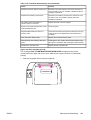
HP Color LaserJet 3500/3550 and 3700
series printers
Service Manual
© 2004 Copyright Hewlett-Packard
Development Company, L.P.
Reproduction, adaptation or translation
without prior written permission is
prohibited, except as allowed under the
copyright laws.
The information contained herein is subject
to change without notice.
The only warranties for HP products and
services are set forth in the express
warranty statements accompanying such
products and services. Nothing herein
should be construed as constituting an
additional warranty. HP shall not be liable
for technical or editorial errors or omissions
contained herein.
Part number: Q5990-90939
Edition 1, 10/2004
Trademark Credits
Microsoft® is a U.S. registered trademark
of Microsoft Corporation.
MS-DOS® is a U.S. registered trademark
of the Microsoft Corporation.
*Pantone®, Inc.'s check-standard
trademark for color.
PostScript® is a trademark of Adobe
Systems Incorporated.
TrueTypeTM is a U.S. trademark of Apple
Computer, Inc.
UNIX® is a registered trademark of The
Open Group.
Windows, MS Windows, and Windows NT
are U.S. registered trademarks of Microsoft
Corporation.
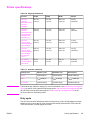
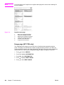
Conventions
This manual uses the following conventions:
Color is used to emphasize items that are important to the material under discussion.
Bold is used for menu items to click and for emphasis, particularly in situations where italic
type would be confusing.
Italic type is used to indicate related documents or emphasis.
DISPLAY type indicates text as seen on the printer control panel display.
Commands you use on a computer keyboard or on the printer control panel are shown in
Keycap. Two examples are MENU and STOP.
COURIER type indicates text that you type on a computer keyboard exactly as shown.
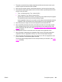
NOTE
Notes contain important information set off from the text.
CAUTION
Caution messages alert you to the possibility of damage to equipment or loss of data.
WARNING!
Warning messages alert you to the possibility of personal injury.
ENWW
Conventions
iii
iv
ENWW
Table of contents
1 Printer description
Chapter contents .......................................................................................................................1
Printer configurations ................................................................................................................3
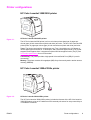
HP Color LaserJet 3500/3550 printer .................................................................................3
HP Color LaserJet 3500n/3550n printer .............................................................................3
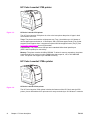
HP Color LaserJet 3700 printer ..........................................................................................4
HP Color LaserJet 3700n printer ........................................................................................4
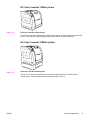
HP Color LaserJet 3700dn printer ......................................................................................5
HP Color LaserJet 3700dtn printer .....................................................................................5
Printer features ..........................................................................................................................6
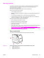
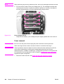
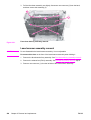
Printer assemblies .....................................................................................................................9
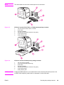
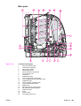
Front and rear features .......................................................................................................9
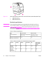
Site requirements ....................................................................................................................11
Space requirements .........................................................................................................11
Electrical specifications ....................................................................................................12
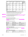
Environmental specifications ............................................................................................13
Printer specifications ...............................................................................................................15
Duty cycle .........................................................................................................................15
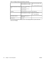
Print media specifications .......................................................................................................16
Supported media weights and sizes .................................................................................16
Hewlett-Packard warranty statement ......................................................................................19
HP's Premium Protection Print Cartridge Warranty Limited Warranty Statement ..................20
Premium Protection Warranty Color LaserJet Image Fuser Kit and Image Transfer
Kit Limited Warranty Statement ...........................................................................................21
Identification ............................................................................................................................22
Model and serial numbers ................................................................................................22
Power and regulatory information ....................................................................................22
Selecting paper .......................................................................................................................24
Paper to avoid ...................................................................................................................24
Paper that can damage the printer ...................................................................................24
Printing on special media ........................................................................................................26
Transparencies .................................................................................................................26
Glossy paper .....................................................................................................................26
Colored paper ...................................................................................................................26
Envelopes .........................................................................................................................27
Labels ...............................................................................................................................27
Heavy paper .....................................................................................................................28
HP LaserJet Tough paper ................................................................................................28
Preprinted forms and letterhead .......................................................................................28
Recycled paper .................................................................................................................29
Media weight .....................................................................................................................29
Environmental product stewardship program .........................................................................31
Protecting the environment ...............................................................................................31
Declaration of Conformities .....................................................................................................34
Safety statements ...................................................................................................................37
Laser safety statement .....................................................................................................37
ENWW
Conventions
v
Canadian DOC regulations ...............................................................................................37
EMI statement (Korea) .....................................................................................................37
VCCI statement (Japan) ...................................................................................................37
Laser statement for Finland ..............................................................................................38
FCC Regulations .....................................................................................................................39
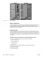
2 Service approach
Chapter contents .....................................................................................................................41
Search approach .....................................................................................................................42
Parts and supplies ...................................................................................................................43
Ordering parts ...................................................................................................................43
Ordering supplies ..............................................................................................................43
Exchange program ...........................................................................................................44
Supplies ............................................................................................................................44
World Wide Web ...............................................................................................................44
HP service parts information CD-ROM ............................................................................44
HP support assistant CD-ROM ........................................................................................44
Customer care reseller sales and service support center ................................................44
Ordering related documentation and software .................................................................45
HP maintenance agreements .................................................................................................46
On-site service agreements ..............................................................................................46
3 Installation and configuration
Chapter contents .....................................................................................................................47
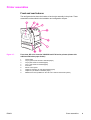
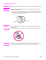
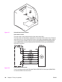
Checking the package contents ..............................................................................................48
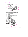
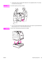
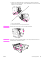
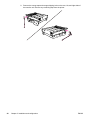
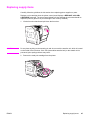
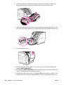
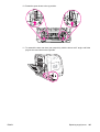
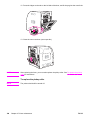
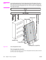
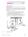
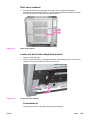
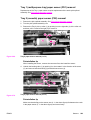
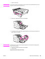
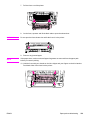
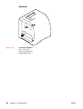
Unpacking the printer ..............................................................................................................50
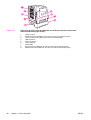
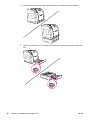
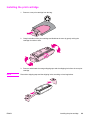
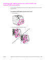
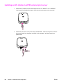
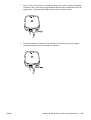
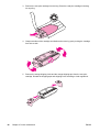
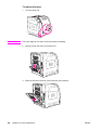
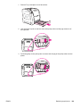
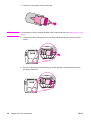
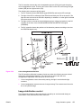
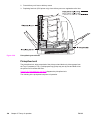
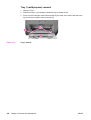
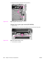
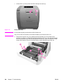
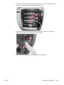
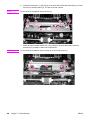
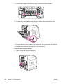
Installing the print cartridge .....................................................................................................55
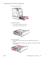
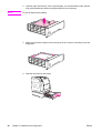
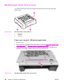
Loading paper into Tray 3 (optional) .......................................................................................57
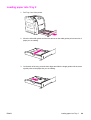
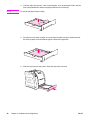
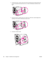
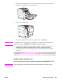
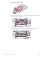
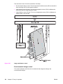
Loading paper into Tray 2 .......................................................................................................59
Loading paper into Tray 1 (optional procedure) ......................................................................61
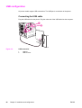
Connecting power ...................................................................................................................62
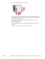
Installing a new control panel overlay (optional) .....................................................................63
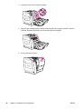
Testing the printer operation ...................................................................................................64
Using PowerSave Time ...........................................................................................................65
To set PowerSave Time ...................................................................................................65
To disable/enable PowerSave ..........................................................................................65
USB configuration ...................................................................................................................66
Connecting the USB cable ...............................................................................................66
Parallel configuration (HP Color LaserJet 3700 series printer only) .......................................67
Network configuration .............................................................................................................68
Enhanced I/O (EIO) configuration (HP color LaserJet 3700 series printer only) ....................69
HP Jetdirect print servers .................................................................................................69
Available enhanced I/O interfaces ....................................................................................69
NetWare networks ............................................................................................................70
Windows and Windows NT networks ...............................................................................70
AppleTalk networks ..........................................................................................................70
UNIX/Linux networks ........................................................................................................70
Printer software .......................................................................................................................71
Printer drivers ...................................................................................................................71
Software for networks .......................................................................................................72
Utilities ..............................................................................................................................73
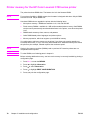
Setting security on the printer .................................................................................................76
Locking the control panel ..................................................................................................76
Using an ASCII PJL escape sequence to set security .....................................................77
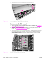
Printer memory for the HP Color LaserJet 3700 series printer ...............................................78
vi
ENWW
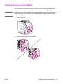
Installing memory and font DIMMs .........................................................................................79
Enabling memory ..............................................................................................................83
Enabling the language font DIMM (HP color LaserJet 3700 only) ...................................83
Checking DIMM installation (HP color LaserJet 3700 only) .............................................84
Installing an HP Jetdirect print server card in the HP color LaserJet 3700 series printer ......85
To install the HP Jetdirect print server card .....................................................................85
Installing an HP Jetdirect en3700 external print server ..........................................................88
4 Printer maintenance
Chapter contents .....................................................................................................................91
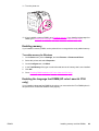
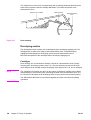
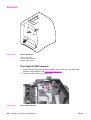
Cleaning the printer and accessories ......................................................................................92
Cleaning spilled toner .......................................................................................................92
Managing supplies ..................................................................................................................94
Supplies life ......................................................................................................................94
Approximate replacement intervals for supplies for the HP Color LaserJet 3500
series printer ..................................................................................................................94
Approximate replacement intervals for supplies for the HP Color LaserJet
3550/3700 series printer ................................................................................................94
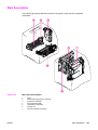
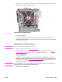
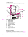
Locating supplies and parts ....................................................................................................96
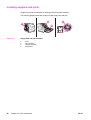
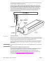
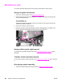
Replacing supply items ...........................................................................................................97
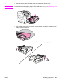
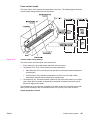
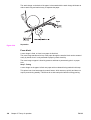
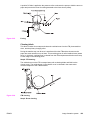
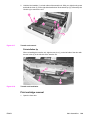
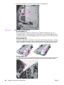
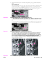
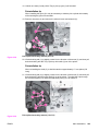
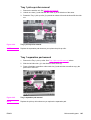
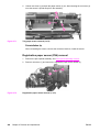
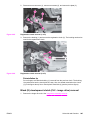
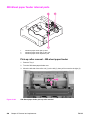
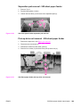
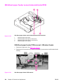
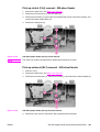
Replacing the transfer unit ................................................................................................99
Replacing the fuser and pickup roller .............................................................................103
5 Theory of operation
Chapter contents ...................................................................................................................113
Basic operation .....................................................................................................................114
Operation sequence .......................................................................................................114
Power-on sequences ......................................................................................................116
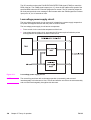
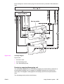
Engine control system ...........................................................................................................119
DC controller PCB ..........................................................................................................119
Low-voltage power supply circuit ...................................................................................126
Low-voltage power supply circuit ...................................................................................131
Laser/scanner system ...........................................................................................................139
Laser control ...................................................................................................................140
Scanner motor control ....................................................................................................144
Image formation system ........................................................................................................146
Print process ...................................................................................................................147
Developing section .........................................................................................................156
Cartridge cleaning control ...............................................................................................163
Transfer section ..............................................................................................................164
ITB cleaning control ........................................................................................................167
Waste toner full detection ...............................................................................................167
Transfer (ITB) unit detection ...........................................................................................168
Transfer unit life detection ..............................................................................................169
ITB self-aligning mechanism ..........................................................................................170
Primary transfer roller engaging/disengaging control ....................................................171
Secondary transfer roller engaging/disengaging control ................................................172
Secondary transfer roller engaging/disengaging detection ............................................173
Color misregistration control ...........................................................................................174
Image stabilization control ..............................................................................................177
Pickup/feed system ...............................................................................................................182
Pickup/feed unit ..............................................................................................................184
Fuser/delivery unit ..........................................................................................................189
Duplexing feed unit (HP 3700 printer only) ....................................................................192
Jam detection .................................................................................................................195
ENWW
Conventions
vii
Paper feeder ..........................................................................................................................197
Pickup/delivery sequence ...............................................................................................198
Paper jam detection ........................................................................................................199
6 Removal and replacement
Chapter contents ...................................................................................................................201
Introduction ............................................................................................................................204
Removal and replacement strategy ................................................................................204
Repair notices .................................................................................................................204
Caution regarding electrostatic discharge (ESD) ...........................................................204
Required tools .................................................................................................................204
Types of screws ..............................................................................................................205
Supplies .................................................................................................................................207
Print cartridges and transfer unit ....................................................................................208
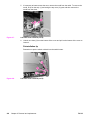
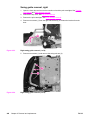
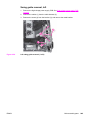
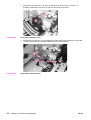
Covers ...................................................................................................................................209
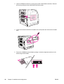
Front door removal .........................................................................................................209
Left cover removal ..........................................................................................................210
Left front cover removal ..................................................................................................211
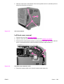
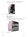
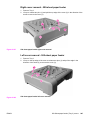
Right cover removal ........................................................................................................213
Top cover removal ..........................................................................................................214
Upper rear door removal ................................................................................................214
Rear cover removal ........................................................................................................215
Lower rear door (rear output bin) removal .....................................................................215
Tray 1 (multipurpose) removal .......................................................................................216
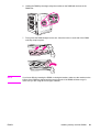
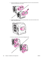
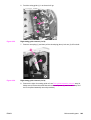
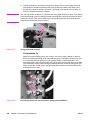
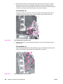
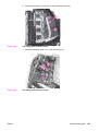
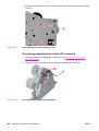
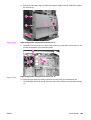
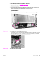
Main Assemblies ...................................................................................................................217
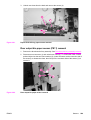
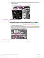
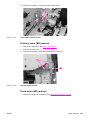
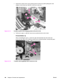
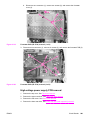
Transfer unit removal ......................................................................................................218
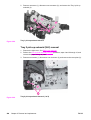
Print cartridge removal ...................................................................................................219
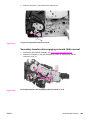
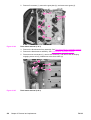
Fuser removal .................................................................................................................220
Face-down delivery assembly removal ..........................................................................221
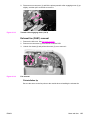
Laser/scanner assembly removal ...................................................................................222
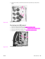
Image drive assembly removal .......................................................................................223
Developing engaging drive assembly removal ...............................................................225
Pick-up/feed assembly removal .....................................................................................225
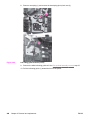
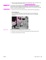
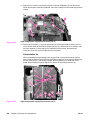
Main assembly parts .............................................................................................................236
Tray 1 pick-up roller removal ..........................................................................................237
Tray 1 separation pad removal .......................................................................................237
Tray 2 pick-up roller removal ..........................................................................................238
Tray 2 separation pad removal .......................................................................................238
Secondary transfer charging roller removal ...................................................................239
Fuser sleeve unit removal ..............................................................................................239
Pressure roller removal ..................................................................................................239
Main thermistor/sub-thermistor removal .........................................................................239
Thermoswitch removal ...................................................................................................239
Feed guide unit removal .................................................................................................240
Swing guide removal, right .............................................................................................242
Swing guide removal, left ...............................................................................................245
Switches ................................................................................................................................250
Door Switch (SW1) removal ...........................................................................................250
Test print switch (SW1001) removal ..............................................................................251
Power switch (SW3001) removal ...................................................................................251
Sensors .................................................................................................................................252
Tray 1 (multipurpose tray) paper sensor (PS1) removal ................................................253
Tray 2 (cassette) paper sensor (PS2) removal ..............................................................253
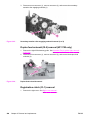
Registration paper sensor (PS4) removal ......................................................................254
Media sensor (PS5) removal ..........................................................................................255
viii
ENWW
Fuser front paper sensor (PS6) removal ........................................................................256
Fuser delivery paper sensor (PS7) removal ...................................................................256
Face-down delivery paper sensor (PS8) removal ..........................................................257
Reversed paper sensor (PS9) removal (HP 3700 only) .................................................257
Duplex feed delivery paper sensor (PS10) removal (HP 3700 only) .............................258
Rear output bin paper sensor (PS11) removal ...............................................................259
Color misregistration sensor (PS12) removal ................................................................260
Waste toner level sensor (PS13) removal ......................................................................260
Developing engaging sensor (PS14) removal ................................................................261
Environment sensor (PS15) removal .............................................................................261
Secondary transfer roller engaging sensor (PS16) removal ..........................................262
Solenoids and Clutches ........................................................................................................263
Tray 1 (multipurpose tray) pick-up solenoid (SL1) removal ...........................................263
Tray 2 pick-up solenoid (SL2) removal ...........................................................................264
Secondary transfer roller engaging solenoid (SL4) removal ..........................................265
Duplex feed solenoid (SL5) removal (HP 3700 only) .....................................................266
Registration clutch (CL1) removal ..................................................................................266
Black (K) development clutch (CL2 - image drive) removal ...........................................267
Developing engaging drive clutch (CL3) removal ..........................................................268
Motor and fans ......................................................................................................................269
Feed motor (M1) removal ...............................................................................................269
Delivery motor (M2) removal ..........................................................................................271
Drum motor (M3) removal ..............................................................................................271
Developing motor (M4) removal .....................................................................................273
Primary transfer roller engaging motor (M5) removal ....................................................274
Exhaust fan (FAN1) removal ..........................................................................................277
Circuit Boards ........................................................................................................................278
DC controller PCB removal ............................................................................................278
Formatter PCB removal ..................................................................................................279
High-voltage power supply PCB removal .......................................................................281
Low-voltage power supply PCB removal .......................................................................285
Memory controller PCB removal ....................................................................................286
Control Panel PCB removal ............................................................................................287
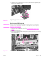
Miscellaneous parts ..............................................................................................................288
Swing rod guide, left removal .........................................................................................288
Swing rod/lock guide, right removal ...............................................................................288
Transfer contact assembly removal ...............................................................................288
Developing contact assembly .........................................................................................288
Tray 2 (cassette) parts removal ............................................................................................291
Tray 2 (cassette) .............................................................................................................291
Cassette (Tray 2) guide, right, removal ..........................................................................291
500-Sheet paper feeder (Tray 3) covers ...............................................................................296
Front cover removal - 500-sheet paper feeder ...............................................................296
Right cover removal - 500-sheet paper feeder ...............................................................297
Left cover removal - 500-sheet paper feeder .................................................................297
500-Sheet paper feeder internal parts ..................................................................................298
Pick-up roller removal - 500-sheet paper feeder ............................................................298
Separation pad removal - 500-sheet paper feeder ........................................................299
Pick-up drive unit removal - 500-sheet paper feeder .....................................................299
500-Sheet paper feeder sensor/solenoid/motor/PCB ...........................................................300
500-Sheet paper feeder PCB removal - 500-sheet feeder ............................................300
Pick-up clutch (CL4) removal - 500-sheet feeder ...........................................................301
Pick-up solenoid (SL3) removal - 500-sheet feeder .......................................................301
Paper sensor (PS3) removal - 500-sheet feeder ...........................................................302
ENWW
Conventions
ix
7 Troubleshooting
Chapter contents ...................................................................................................................303
Introduction ............................................................................................................................306
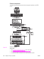
Troubleshooting process .......................................................................................................307
Pre-troubleshooting checklist .........................................................................................307
Troubleshooting flowchart ..............................................................................................308
Troubleshooting power-on ..............................................................................................310
Printer error troubleshooting .................................................................................................312
Status messages ............................................................................................................312
Warning messages .........................................................................................................312
Error messages ..............................................................................................................312
Critical error messages ...................................................................................................312
Alphabetical printer messages .......................................................................................312
Numerical printer messages ...........................................................................................327
Replacement parts configuration ..........................................................................................352
Formatter and DC Controller replaced at the same time ...............................................352
Formatter (New) replacement configuration ...................................................................352
Formatter (previously installed in another printer) replacement configuration ...............353
DC Controller (New) replacement configuration ............................................................353
DC Controller (previously installed in another printer) replacement configuration ........354
Media sensor (PS5) replacement configuration .............................................................354
Color Misregistration Sensor (PS12) replacement configuration ...................................355
Laser/scanner Assembly replacement configuration .....................................................355
Fuser replacement configuration ....................................................................................355
Transfer unit (ITB assembly) replacement configuration ...............................................355
Paper path troubleshooting ...................................................................................................356
Paper path jam areas .....................................................................................................357
Paper jam error message ...............................................................................................357
Paper path areas jam troubleshooting ...........................................................................360
Paper jam recovery feature ............................................................................................377
Avoiding paper jams .......................................................................................................377
General paper path troubleshooting ...............................................................................379
Persistent jams ...............................................................................................................380
Image formation troubleshooting ..........................................................................................381
Print quality problems associated with media ................................................................381
Overhead transparency defect .......................................................................................381
Print quality problems associated with the environment ................................................382
Print quality problems associated with paper jams ........................................................382
Print quality problems associated with toner buildup .....................................................382
Print quality troubleshooting pages ................................................................................383
Calibrating the printer .....................................................................................................383
Using Color ...........................................................................................................................384
HP ImageREt 2400 .........................................................................................................384
Paper selection ...............................................................................................................384
Color options (available for the HP Color LaserJet 3700 series printer) ........................384
Standard red-green-blue (sRGB) ...................................................................................384
Printing in four-colors [CMYK (available for the HP Color LaserJet 3700 series
printer) .........................................................................................................................385
CMYK ink set emulation (PostScript only) .....................................................................385
Managing color ......................................................................................................................386
Print in Grayscale ...........................................................................................................386
Automatic or manual color adjustment ...........................................................................386
Manual color options ......................................................................................................386
Matching colors .....................................................................................................................388
Swatch book color matching (HP Color LaserJet 3700 series printer only) ...................388
Adjusting color balance ..................................................................................................389
x
ENWW
Image defects ........................................................................................................................390
Light image ....................................................................................................................391
Light color .......................................................................................................................392
Dark image ...................................................................................................................392
Dark color .......................................................................................................................393
Completely blank image .................................................................................................393
All black or solid color ....................................................................................................393
Dots in vertical lines .......................................................................................................394
Dirt on back of paper ......................................................................................................394
Dirt on front of paper .......................................................................................................394
Vertical lines ..................................................................................................................395
White vertical lines ..........................................................................................................395
Horizontal line .................................................................................................................396
White horizontal line .......................................................................................................396
Color missing ..................................................................................................................397
Blank spots .....................................................................................................................397
Poor fusing ....................................................................................................................397
Image distortion ..............................................................................................................398
Color misregistration .......................................................................................................398
Smearing ........................................................................................................................399
Misplaced image .............................................................................................................399
Reversed color ................................................................................................................400
Snail tracks .....................................................................................................................400
Repetitive defects troubleshooting ........................................................................................401
Interface troubleshooting ......................................................................................................403
Communications checks .................................................................................................403
EIO troubleshooting ........................................................................................................403
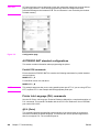
AUTOEXEC.BAT standard configurations .....................................................................404
Printer Job Language (PJL) commands .........................................................................404
@PJL COMMENT ..........................................................................................................405
@PJL INFO CONFIG .....................................................................................................405
@PJL INFO ID ................................................................................................................405
@PJL INFO USTATUS ..................................................................................................405
@PJL INFO PAGECOUNT ............................................................................................405
@PJL JOB ......................................................................................................................406
@PJL EOJ ......................................................................................................................406
@PJL ECHO ...................................................................................................................406
@PJL USTATUS JOB=ON/OFF ....................................................................................406
@PJL USTATUSOFF .....................................................................................................406
Control panel troubleshooting ...............................................................................................407
Printing a menu map ......................................................................................................407
Information menu ............................................................................................................407
Paper handling menu .....................................................................................................408
Configure device menu ...................................................................................................409
Print quality menu ...........................................................................................................411
System setup menu ........................................................................................................414
I/O menu .........................................................................................................................418
Resets menu ...................................................................................................................419
Diagnostics menu ...........................................................................................................419
Service menu ..................................................................................................................420
Tools for troubleshooting ......................................................................................................422
Embedded Web server (HP Color LaserJet 3700 series printer only) ...........................422
HP Toolbox .....................................................................................................................424
Printer configuration page ..............................................................................................428
Supplies status page ......................................................................................................429
Usage page (HP 3700 only) ...........................................................................................430
ENWW
Conventions
xi
Event log .........................................................................................................................431
Diagnostics ............................................................................................................................433
Diagnostics flowchart ......................................................................................................433
Engine diagnostics .........................................................................................................434
Diagnostics from the Control Panel ......................................................................................436
Printer display menu .......................................................................................................436
Diagnostics test menu ....................................................................................................436
Paper Path Test ..............................................................................................................439
Component Test – special mode test .............................................................................439
Print/Stop Test ................................................................................................................442
Information menu ............................................................................................................443
Configure device menu/printing menu ............................................................................443
Configure device menu/resets menu ..............................................................................443
Configure device menu/print quality menu .....................................................................443
Test pages .............................................................................................................................445
Engine test page .............................................................................................................445
Formatter test page ........................................................................................................445
Engine resets ........................................................................................................................446
Cold reset .......................................................................................................................446
NVRAM initialization .......................................................................................................446
Calibration bypass ..........................................................................................................447
Calibrate Now .................................................................................................................447
Service menu ........................................................................................................................448
Accessing the Service menu ..........................................................................................448
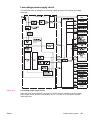
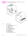
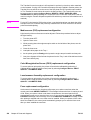
Diagrams ...............................................................................................................................450
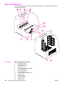
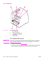
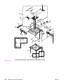
Main parts .......................................................................................................................451
Switches .........................................................................................................................452
Sensors ...........................................................................................................................453
Solenoids and clutches ...................................................................................................454
Motors and fans ..............................................................................................................455
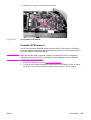
PCBs ...............................................................................................................................456
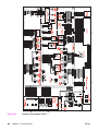
Connector locations ........................................................................................................458
500-sheet paper feeder connectors ...............................................................................462
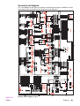
General circuit diagram ..................................................................................................463
8 Parts and diagrams
Chapter contents ...................................................................................................................465
Introduction ............................................................................................................................466
Ordering parts .......................................................................................................................467
Supplies and accessories ...............................................................................................467
Replacement parts configuration ....................................................................................473
Illustrations and parts lists .....................................................................................................478
Alphabetical parts list.............................................................................................................538
Numerical parts list.................................................................................................................551
Index
xii
ENWW
List of tables
Table 1-1.
Table 1-2.
Table 1-3.
Table 1-4.
Table 1-5.
Table 1-6.
Table 1-7.
Table 1-8.
Table 1-9.
Table 1-10.
Table 1-11.
Table 1-12.
Table 1-13.
Table 2-1.
Table 3-1.
Table 3-2.
Table 3-3.
Table 3-4.
Table 4-1.
Table 4-2.
Table 4-3.
Table 5-1.
Table 5-2.
Table 5-3.
Table 5-4.
Table 5-5.
Table 5-6.
Table 6-1.
Table 6-2.
Table 6-3.
Table 7-1.
Table 7-2.
Table 7-3.
Table 7-4.
Table 7-5.
Table 7-6.
Table 7-7.
Table 7-8.
Table 7-9.
Table 7-10.
Table 7-11.
Table 7-12.
Table 7-13.
Table 7-14.
Table 7-15.
ENWW
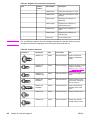
Features ............................................................................................................6
Electrical specifications ...................................................................................12
Power consumption for 110 and 220-volt (average in watts)1 ........................12
Environmental specifications ..........................................................................13
Supply storage requirements ..........................................................................13
Physical dimensions ........................................................................................15
Acoustic emissions ..........................................................................................15
Tray 1 paper sizes1 .........................................................................................16
Tray 2 paper sizes1 .........................................................................................17
Tray 3 paper sizes1 .........................................................................................17
Automatic two-sided printer (available on some models of the
HP Color LaserJet 3700 series printer)1 .........................................................17
Model names and numbers ............................................................................22
Weight equivalence table ................................................................................29
Related documentation and software .............................................................45
Printer drivers for the HP Color LaserJet 3500/3550 series printer ................71
Printer drivers for the HP Color LaserJet 3700 series printer .........................72
Other software applications ............................................................................75
Printer security levels ......................................................................................76
Cleaning the printer .........................................................................................92
Approximate replacement intervals .................................................................94
Approximate replacement intervals .................................................................95
Basic operation sequence .............................................................................115
Motor Functions ............................................................................................122
Function of solenoids ....................................................................................123
Function of clutches ......................................................................................123
Print media and feed speeds ........................................................................187
Conditions of available duplex feed ..............................................................195
Common fasteners ........................................................................................205
Approximate replacement intervals for print cartridges ................................207
Approximate replacement intervals for supply items ....................................207
Pre-troubleshooting checklist ........................................................................307
Alphabetical printer messages ......................................................................313
Numerical printer messages .........................................................................328
Error messages and associated jam locations .............................................358
Causes for multiple pages feeding ................................................................360
Causes for jams in the Tray 1 pick-up area ..................................................360
Causes for jams in the Tray 2 area ...............................................................361
Causes for jams in the fuser/face-down delivery area ..................................361
Transfer/feed area .........................................................................................362
Causes for wrinkled or folded paper (paper path entrance) .........................368
Causes for wrinkled or folded paper (paper path exit) ..................................368
Causes for skewed paper .............................................................................368
Causes for jams in the duplex area (HP 3700 (only) ....................................369
Fuser/face-down delivery area ......................................................................370
Common causes of paper jams ....................................................................378
Conventions
xiii
Table 7-16.
Table 7-17.
Table 7-18.
Table 7-19.
Table 7-20.
Table 7-21.
Table 7-22.
Table 7-23.
Table 7-24.
Table 7-25.
Table 7-26.
Table 7-27.
Table 7-28.
Table 7-29.
Table 7-30.
Table 7-31.
Table 7-32.
Table 7-33.
Table 7-34.
Table 7-35.
Table 7-36.
Table 7-37.
Table 7-38.
Table 7-39.
Table 7-40.
Table 7-41.
Table 7-42.
Table 7-43.
Table 7-44.
Table 7-45.
Table 7-46.
Table 7-47.
Table 7-48.
Table 7-49.
Table 7-50.
Table 8-1.
Table 8-2.
Table 8-3.
Table 8-4.
Table 8-5.
Table 8-6.
Table 8-7.
Table 8-8.
Table 8-9.
Table 8-10.
Table 8-11.
Table 8-12.
Table 8-13.
Table 8-14.
Table 8-15.
Table 8-16.
Table 8-17.
Table 8-18.
Table 8-19.
Table 8-20.
Table 8-21.
xiv
Image defects ................................................................................................390
Causes for light images .................................................................................391
Causes for one color printing light ................................................................392
Causes for dark images ................................................................................392
Causes for one color printing dark ................................................................393
Causes for a completely blank image ...........................................................393
Causes for an all black or solid colored image .............................................393
Causes for vertical lines of white dots ..........................................................394
Causes for dirt on the back of the paper .......................................................394
Causes for dirt on the front of the paper .......................................................395
Causes for vertical lines ................................................................................395
Causes for white vertical lines ......................................................................395
Causes for horizontal line .............................................................................396
Causes for white horizonal lines ...................................................................396
Causes for a missing color ............................................................................397
Causes for blank spots ..................................................................................397
Causes for poor fusing ..................................................................................397
Causes for distortion or blurring ....................................................................398
Causes for smearing .....................................................................................398
Causes for smearing .....................................................................................399
Causes for a misplaced image ......................................................................399
Causes for reversed color .............................................................................400
Causes for reversed color .............................................................................400
Repetitive defect cause .................................................................................401
Communications check .................................................................................403
Information menu ..........................................................................................408
Paper handling menu ....................................................................................408
Printing menu ................................................................................................409
Print quality menu .........................................................................................412
System setup submenu .................................................................................415
I/O submenu ..................................................................................................418
Resets submenu ...........................................................................................419
Diagnostics menu ..........................................................................................419
Service menu ................................................................................................420
Paper path and manual sensor test control panel information .....................438
Supplies and accessories .............................................................................467
Common fasteners ........................................................................................472
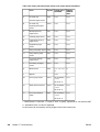
PCB locations ................................................................................................481
Paper feeder PCB Assembly Location diagram ...........................................483
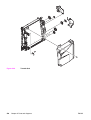
External covers and panels ...........................................................................485
Front door assembly .....................................................................................487
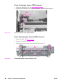
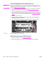
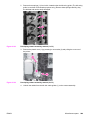
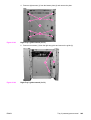
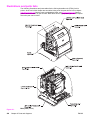
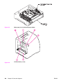
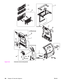
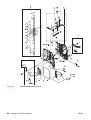
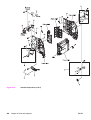
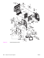
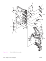
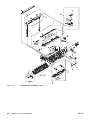
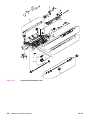
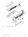
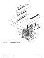
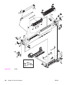
Internal components (1 of 4) .........................................................................489
Internal components (2 of 4) .........................................................................491
Internal components (3 of 4) .........................................................................495
Internal components (4 of 4) .........................................................................497
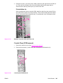
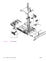
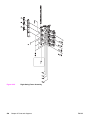
Center Frame Assembly ...............................................................................499
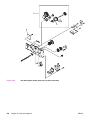
Main Right Side Plate Assembly / Motors .....................................................501
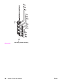
Main Left Side Plate Assembly .....................................................................505
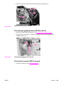
Image drive assembly ...................................................................................511
Developing Disengaging Assembly ..............................................................513
Tray 2 (cassette) ...........................................................................................515
Pick-up/Feed assembly .................................................................................519
Tray 2 (cassette) pick-up assembly ..............................................................521
Face-down delivery assembly .......................................................................523
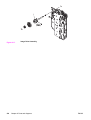
Transfer unit ..................................................................................................525
Right Swing Frame Assembly .......................................................................527
ENWW
Table 8-22.
Table 8-23.
Table 8-24.
Table 8-25.
Table 8-26.
Table 8-27.
Table 8-28.
ENWW
Left swing frame assembly ...........................................................................529
Fuser assembly .............................................................................................531
500-Sheet paper feeder main body ..............................................................533
500-Sheet paper feeder paper pick-up drive assembly ................................535
500-Sheet paper feeder tray (Tray 3) ...........................................................537
Alphabetical parts list.....................................................................................538
Numerical parts list.........................................................................................551
Conventions
xv
xvi
ENWW
List of figures
Figure 1-1.
Figure 1-2.
Figure 1-3.
Figure 1-4.
Figure 1-5.
Figure 1-6.
Figure 1-7.
Figure 1-8.
Figure 1-9.
Figure 1-10.
Figure 1-11.
Figure 1-12.
Figure 1-13.
Figure 1-14.
Figure 3-1.
Figure 3-2.
Figure 3-3.
Figure 3-4.
Figure 3-5.
Figure 3-6.
Figure 4-1.
Figure 4-2.
Figure 4-3.
Figure 5-1.
Figure 5-2.
Figure 5-3.
Figure 5-4.
Figure 5-5.
Figure 5-6.
Figure 5-7.
Figure 5-8.
Figure 5-9.
Figure 5-10.
Figure 5-11.
Figure 5-12.
Figure 5-13.
Figure 5-14.
Figure 5-15.
Figure 5-16.
Figure 5-17.
Figure 5-18.
Figure 5-19.
ENWW
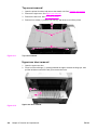
HP Color LaserJet 3500/3550 printer ...............................................................3
HP Color LaserJet 3500n/3550n printer ...........................................................3
HP Color LaserJet 3700 printer ........................................................................4
HP Color LaserJet 3700n printer ......................................................................4
HP Color LaserJet 3700dn printer ....................................................................5
HP Color LaserJet 3700dtn printer ...................................................................5
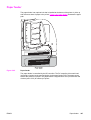
Front view, HP Color LaserJet 3500/3550 and 3700 series printers
(shown with additional 500-sheet paper feeder) ...............................................9
Rear view, HP Color LaserJet 3500/3550 and 3700 series printers
(shown with additional 500-sheet paper feeder) .............................................10
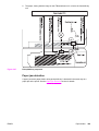
Space requirements for the HP Color LaserJet 3500/3550 series printer ......11
Space requirements for the HP Color LaserJet 3700 series printer
with optional Tray 3 .........................................................................................12
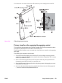
Serial number information ...............................................................................22
Sample label ....................................................................................................23
EMI statement for Korea .................................................................................37
VCCI statement for Japan ...............................................................................37
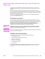
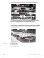
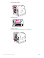
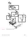
HP Color LaserJet 3500/3550 printer package contents ................................48
Additional contents shipped with the HP Color LaserJet 3500n/3550n
printer ..............................................................................................................48
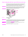
HP Color LaserJet 3700, 3700n, or 3700dn printer package contents ..........49
HP Color LaserJet 3700dtn printer package contents ....................................49
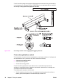
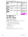
USB connection ..............................................................................................66
Parallel port connection ...................................................................................67
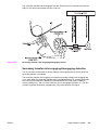
Toner specks ...................................................................................................93
Toner smearing ...............................................................................................93
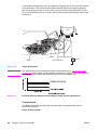
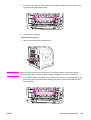
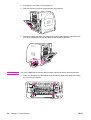
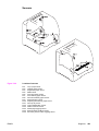
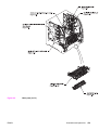
Supply item and part locations ........................................................................96
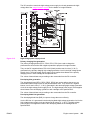
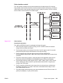
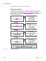
Basic system operation .................................................................................114
Power-on sequence ......................................................................................116
Timing diagram .............................................................................................118
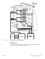
Engine control system ...................................................................................119
DC controller circuit .......................................................................................120
Motor locations ..............................................................................................123
Solenoid and clutch locations .......................................................................124
Drum motor control circuit .............................................................................124
Developing motor control circuit ....................................................................125
Fan control circuit ..........................................................................................125
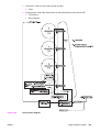
Low-voltage power supply circuit ..................................................................126
Ceramic heater fusing method ......................................................................127
Heater temperature control circuit .................................................................128
Low-voltage power supply circuit ..................................................................131
High-voltage power supply circuit .................................................................133
Video interface ..............................................................................................135
Video interface signals ..................................................................................136
Output timing of the VIDEO signal in response to the /TOP signal ..............137
Output timing of the VIDEO signal synchronized with the /BD signal ..........138
Conventions
xvii
Figure 5-20.
Figure 5-21.
Figure 5-22.
Figure 5-23.
Figure 5-24.
Figure 5-25.
Figure 5-26.
Figure 5-27.
Figure 5-28.
Figure 5-29.
Figure 5-30.
Figure 5-31.
Figure 5-32.
Figure 5-33.
Figure 5-34.
Figure 5-35.
Figure 5-36.
Figure 5-37.
Figure 5-38.
Figure 5-39.
Figure 5-40.
Figure 5-41.
Figure 5-42.
Figure 5-43.
Figure 5-44.
Figure 5-45.
Figure 5-46.
Figure 5-47.
Figure 5-48.
Figure 5-49.
Figure 5-50.
Figure 5-51.
Figure 5-52.
Figure 5-53.
Figure 5-54.
Figure 5-55.
Figure 5-56.
Figure 5-57.
Figure 5-58.
Figure 5-59.
Figure 5-60.
Figure 5-61.
Figure 5-62.
Figure 5-63.
Figure 5-64.
Figure 5-65.
Figure 5-66.
Figure 5-67.
Figure 6-1.
Figure 6-2.
Figure 6-3.
Figure 6-4.
Figure 6-5.
Figure 6-6.
Figure 6-7.
xviii
Laser/scanner unit .........................................................................................139
Laser control block diagram ..........................................................................141
Image mask control .......................................................................................143
Scanner motor control ...................................................................................144
Image formation system ................................................................................146
Image formation system (signal paths) .........................................................147
Print process diagram ...................................................................................149
Electrostatic latent image formation ..............................................................150
Primary charging ...........................................................................................150
Laser beam exposure ...................................................................................151
Image development .......................................................................................152
Potential difference between the developing cylinder and the exposed
area ...............................................................................................................152
Primary transfer .............................................................................................153
Secondary transfer ........................................................................................153
Separation .....................................................................................................154
Fusing ............................................................................................................155
ITB cleaning ..................................................................................................155
Drum cleaning ...............................................................................................156
Cartridge diagram .........................................................................................157
Developing engaging/disengaging unit .........................................................159
Memory tag control .......................................................................................160
Cartridge presence detection ........................................................................161
Toner level detection .....................................................................................162
Transfer section diagram ..............................................................................164
Transfer section ............................................................................................166
ITB cleaning control ......................................................................................167
Waste toner full detection .............................................................................168
Transfer unit detection ..................................................................................169
Transfer unit life detection control .................................................................169
ITB self-aligning mechanism .........................................................................171
Primary transfer roller engaging/disengaging control ...................................172
Secondary transfer roller engaging/disengaging control ..............................173
Secondary transfer roller engaging/disengaging detection ..........................174
Color misregistration control .........................................................................176
Color misregistration detection .....................................................................177
Image stabilization control ............................................................................178
Image density detection ................................................................................180
Pickup/feed system .......................................................................................183
Pickup/feed system blocks ............................................................................184
Pickup/delivery unit block ..............................................................................186
Skew control mechanism ..............................................................................188
Media detection .............................................................................................189
Fuser/delivery unit .........................................................................................191
Duplexing unit ...............................................................................................193
Reverse control .............................................................................................194
Paper feeder .................................................................................................197
Paper feeder PCB signal flow .......................................................................198
Pickup/delivery sequence .............................................................................199
Phillips and Posidrive screwdriver comparison .............................................205
Cover locations .............................................................................................209
Front door removal (1 of 2) ...........................................................................210
Front door removal (2 of 2) ...........................................................................210
Left cover removal .........................................................................................211
Left front cover removal (1 of 3) ....................................................................211
Left front cover removal (2 of 4) ....................................................................212
ENWW
Figure 6-8.
Figure 6-9.
Figure 6-10.
Figure 6-11.
Figure 6-12.
Figure 6-13.
Figure 6-14.
Figure 6-15.
Figure 6-16.
Figure 6-17.
Figure 6-18.
Figure 6-19.
Figure 6-20.
Figure 6-21.
Figure 6-22.
Figure 6-23.
Figure 6-24.
Figure 6-25.
Figure 6-26.
Figure 6-27.
Figure 6-28.
Figure 6-29.
Figure 6-30.
Figure 6-31.
Figure 6-32.
Figure 6-33.
Figure 6-34.
Figure 6-35.
Figure 6-36.
Figure 6-37.
Figure 6-38.
Figure 6-39.
Figure 6-40.
Figure 6-41.
Figure 6-42.
Figure 6-43.
Figure 6-44.
Figure 6-45.
Figure 6-46.
Figure 6-47.
Figure 6-48.
Figure 6-49.
Figure 6-50.
Figure 6-51.
Figure 6-52.
Figure 6-53.
Figure 6-54.
Figure 6-55.
Figure 6-56.
Figure 6-57.
Figure 6-58.
Figure 6-59.
Figure 6-60.
Figure 6-61.
Figure 6-62.
Figure 6-63.
ENWW
Left front cover removal (2 of 3) ....................................................................212
Left front cover removal (3 of 3) ....................................................................213
Right cover removal ......................................................................................213
Top cover removal ........................................................................................214
Upper rear door removal ...............................................................................214
Rear cover removal .......................................................................................215
Lower rear door removal ...............................................................................215
Tray 1 removal ..............................................................................................216
Main internal assemblies ...............................................................................217
Transfer unit removal ....................................................................................219
Transfer unit installation ................................................................................219
Print cartridge removal ..................................................................................220
Fuser removal ...............................................................................................221
Face-down delivery assembly removal .........................................................222
Laser/scanner assembly removal .................................................................223
Image drive assembly removal .....................................................................224
Developing engaging drive assembly removal .............................................225
Pick-up/feed assembly removal (1 of 13) .....................................................226
Pick-up/feed assembly removal (2 of 13) .....................................................226
Pick-up/feed assembly removal (3 of 13) .....................................................227
Right swing rod arm reassembly ...................................................................227
Pick-up/feed assembly removal (4 of 13) .....................................................228
Pick-up/feed engaging rack assembly replacement (1 of 2) .........................229
Pick-up/feed engaging rack assembly replacement (2 of 2) .........................229
Print cartridge engaging pins replacement ...................................................229
Pick-up/feed assembly removal (5 of 13) .....................................................230
Pick-up/feed assembly removal (6 of 13) .....................................................231
Gear plate gear locations replacement .........................................................231
Pick-up/feed assembly removal (7 of 13) .....................................................232
Pick-up/feed assembly removal (8 of 13) .....................................................232
Pick-up/feed assembly removal (9 of 13) .....................................................233
Pick-up/feed assembly removal (10 of 13) ...................................................233
Pick-up/feed assembly removal (11 of 13) ...................................................234
Pick-up/feed assembly removal (12 of 13) ...................................................234
Pick-up/feed assembly removal (13 of 13) ...................................................235
Main assemblies parts location .....................................................................236
Tray 1 pick-up roller removal ........................................................................237
Tray 1 separation pad removal .....................................................................237
Tray 2 pick-up roller removal ........................................................................238
Tray 2 separation pad removal .....................................................................238
Secondary transfer charging roller removal ..................................................239
Feed guide unit removal (1 of 2) ...................................................................240
Feed guide removal (2 of 2) ..........................................................................241
Feed guide/printer drive shaft connection .....................................................241
Feed guide unit tab locations ........................................................................241
Right swing guide removal (1 of 4) ...............................................................242
Right swing guide removal (2 of 4) ...............................................................242
Right swing guide removal (3 of 4) ...............................................................243
Right swing guide removal (4 of 4) ...............................................................243
Swing guide shaft removal ............................................................................244
Developing (drum) lock arm position for swing guide installation .................244
Left swing guide removal (1 of 6) ..................................................................245
Left swing guide removal (2 of 6) ..................................................................246
Left swing guide removal (3 of 6) ..................................................................246
Left swing guide removal (4 of 6) ..................................................................247
Left swing guide removal (5 of 6) ..................................................................247
Conventions
xix
Figure 6-64.
Figure 6-65.
Figure 6-66.
Figure 6-67.
Figure 6-68.
Figure 6-69.
Figure 6-70.
Figure 6-71.
Figure 6-72.
Figure 6-73.
Figure 6-74.
Figure 6-75.
Figure 6-76.
Figure 6-77.
Figure 6-78.
Figure 6-79.
Figure 6-80.
Figure 6-81.
Figure 6-82.
Figure 6-83.
Figure 6-84.
Figure 6-85.
Figure 6-86.
Figure 6-87.
Figure 6-88.
Figure 6-89.
Figure 6-90.
Figure 6-91.
Figure 6-92.
Figure 6-93.
Figure 6-94.
Figure 6-95.
Figure 6-96.
Figure 6-97.
Figure 6-98.
Figure 6-99.
Figure 6-100.
Figure 6-101.
Figure 6-102.
Figure 6-103.
Figure 6-104.
Figure 6-105.
Figure 6-106.
Figure 6-107.
Figure 6-108.
Figure 6-109.
Figure 6-110.
Figure 6-111.
Figure 6-112.
Figure 6-113.
Figure 6-114.
Figure 6-115.
Figure 6-116.
Figure 6-117.
Figure 6-118.
Figure 6-119.
xx
Left swing guide removal (6 of 6) ..................................................................248
Left swing guide replacement .......................................................................249
Switch locations ............................................................................................250
Door switch removal ......................................................................................250
Sensor locations ............................................................................................252
Tray 2 paper sensor removal (1 of 3) ............................................................253
Tray 2 paper sensor removal (2 of 3) ............................................................253
Tray paper sensor removal (3 of 3) ...............................................................254
Registration paper sensor removal (1 of 2) ..................................................254
Registration paper sensor removal (2 of 2) ..................................................255
Media sensor removal ...................................................................................255
Fuser front paper sensor (PS6) removal ......................................................256
Fuser delivery paper sensor removal (1 of 2) ...............................................256
Fuser delivery paper sensor removal (2 of 2) ...............................................257
Face-down (output bin) delivery paper sensor removal ...............................257
Reversed paper sensor removal (1 of 2) ......................................................258
Reversed paper sensor removal (2 of 2) ......................................................258
Duplex feed delivery paper sensor removal .................................................259
Rear output bin paper sensor removal .........................................................259
Color misregistration sensor removal ...........................................................260
Waste toner level sensor removal .................................................................261
Developing engaging sensor removal ..........................................................261
Environmental sensor removal .....................................................................262
Secondary transfer roller engaging sensor removal .....................................262
Solenoid and clutch locations .......................................................................263
Tray 1 pick-up solenoid removal ...................................................................264
Tray 2 pick-up solenoid removal (1 of 2) ......................................................264
Tray 2 pick-up solenoid removal (2 of 2) ......................................................265
Secondary transfer roller engaging solenoid removal (1 of 2) ......................265
Secondary transfer roller engaging solenoid removal (2 of 2) ......................266
Duplex feed solenoid removal .......................................................................266
Registration clutch removal (1 of 2) ..............................................................267
Registration clutch removal (2 of 2) ..............................................................267
Black development clutch removal (2 of 2) ...................................................268
Developing engaging drive clutch removal ...................................................268
Motor and fan locations .................................................................................269
Feed motor removal (1 of 3) .........................................................................270
Feed motor removal (2 of 3) .........................................................................270
Feed motor removal (3 of 3) .........................................................................271
Delivery motor removal .................................................................................271
Drum motor removal (1 of 3) .........................................................................272
Drum motor removal (2 of 3) .........................................................................272
Drum motor removal (3 of 3) .........................................................................273
Developing motor removal (1 of 3) ................................................................273
Developing motor removal (2 of 3) ................................................................274
Developing motor removal (3 of 3) ................................................................274
Primary transfer roller engaging motor removal (1 of 4) ...............................275
Primary transfer roller engaging motor removal (2 of 4) ...............................276
Transfer roller engaging motor removal (3 of 4) ...........................................276
Transfer roller engaging motor (4 of 4) .........................................................277
Fan removal ..................................................................................................277
Circuit board locations ...................................................................................278
DC controller PCB removal ...........................................................................279
Formatter PCB (HP 3500/3550) removal (1 of 2) .........................................280
Formatter PCB (HP 3500/3500) removal (2 of 2) .........................................280
Formatter PCB (HP 3700) removal (1 of 2) ..................................................281
ENWW
Figure 6-120.
Figure 6-121.
Figure 6-122.
Figure 6-123.
Figure 6-124.
Figure 6-125.
Figure 6-126.
Figure 6-127.
Figure 6-128.
Figure 6-129.
Figure 6-130.
Figure 6-131.
Figure 6-132.
Figure 6-133.
Figure 6-134.
Figure 6-135.
Figure 6-136.
Figure 6-137.
Figure 6-138.
Figure 6-139.
Figure 6-140.
Figure 6-141.
Figure 6-142.
Figure 6-143.
Figure 6-144.
Figure 6-145.
Figure 6-146.
Figure 6-147.
Figure 6-148.
Figure 6-149.
Figure 6-150.
Figure 6-151.
Figure 6-152.
Figure 6-153.
Figure 6-154.
Figure 6-155.
Figure 6-156.
Figure 6-157.
Figure 6-158.
Figure 7-1.
Figure 7-2.
Figure 7-3.
Figure 7-4.
Figure 7-5.
Figure 7-6.
Figure 7-7.
Figure 7-8.
Figure 7-9.
Figure 7-10.
Figure 7-11.
Figure 7-12.
Figure 7-13.
Figure 7-14.
Figure 7-15.
Figure 7-16.
Figure 7-17.
ENWW
Formatter PCB (HP 3700) removal (2 of 2) ..................................................281
HP 3500/3550 and HP 3700 .........................................................................282
High-voltage power supply PCB removal (1 of 5) .........................................282
High-voltage power supply PCB removal (2 of 5) .........................................283
High-voltage power supply PCB removal (3 or 5) .........................................283
High-voltage power supply PCB removal (4 of 5) .........................................284
High-voltage power supply PCB removal (5 of 5) .........................................284
Low voltage power supply PCB removal (1 of 2) ..........................................285
Left front cover removal (2 of 4) ....................................................................285
Low voltage power supply PCB removal (2 of 2) ..........................................286
Memory controller PCB removal (1 of 2) ......................................................286
Memory controller PCB removal (2 of 2) ......................................................287
Control panel PCB removal ..........................................................................287
Developing contact assembly removal (1 of 3) .............................................289
Developing contact assembly removal (2 of 3) .............................................289
Developing contact assembly removal (3 of 3) .............................................290
Right Tray 2 guide removal (1 of 6) ..............................................................291
Right Tray 2 guide removal (2 of 6) ..............................................................292
Right Tray 2 guide removal (3 of 6) ..............................................................292
Right Tray 2 guide removal (4 of 6) ..............................................................293
Right Tray 2 guide removal (5 of 6) ..............................................................293
Right tray guide removal (6 of 6) ...................................................................294
Right Tray 2 guide removal (1 of 3) ..............................................................294
Right Tray 2 guide removal (2 of 3) ..............................................................295
Right Tray 2 guide removal (3 of 3) ..............................................................295
500-Sheet feeder cover locations .................................................................296
500-Sheet paper feeder front cover removal ................................................296
500-sheet paper feeder right cover removal .................................................297
500-sheet paper feeder left cover removal ...................................................297
500-Sheet paper feeder pick-up roller removal ............................................298
500-sheet paper feeder separation pad removal ..........................................299
500-Sheet paper feeder pick-up drive unit removal ......................................299
500-Sheet paper feeder sensor/solenoid/motor/PCB locations ...................300
500-Sheet paper feeder PCB removal ..........................................................300
500-Sheet paper feeder pick-up clutch removal ...........................................301
500-Sheet paper feeder pick-up solenoid removal .......................................301
500-Sheet paper feeder front frame removal (1 of 3) ...................................302
500-Sheet feeder paper sensor removal (2 of 3) ..........................................302
500-Sheet feeder paper sensor removal (3 of 3) ..........................................302
Jam area locations and sensor positions ......................................................357
Printer front door ...........................................................................................364
Left side of front door ....................................................................................367
Repetitive defects ruler .................................................................................402
Configuration page ........................................................................................404
Printer menu map (HP 3700 shown) .............................................................407
Printer configuration page .............................................................................428
EIO page .......................................................................................................429
Supplies status page .....................................................................................430
Usage page ...................................................................................................431
Event log .......................................................................................................432
Diagnostics flowchart ....................................................................................433
Formatter LED ...............................................................................................434
Location of sensors .......................................................................................437
Location of motors and fans ..........................................................................440
Location of solenoids and clutches ...............................................................441
Test page switch ...........................................................................................445
Conventions
xxi
Figure 7-18.
Figure 7-19.
Figure 7-20.
Figure 7-21.
Figure 7-22.
Figure 7-23.
Figure 7-24.
Figure 7-25.
Figure 7-26.
Figure 7-27.
Figure 7-28.
Figure 7-29.
Figure 7-30.
Figure 7-31.
Figure 7-32.
Figure 8-1.
Figure 8-2.
Figure 8-3.
Figure 8-4.
Figure 8-5.
Figure 8-6.
Figure 8-7.
Figure 8-8.
Figure 8-9.
Figure 8-10.
Figure 8-11.
Figure 8-12.
Figure 8-13.
Figure 8-14.
Figure 8-15.
Figure 8-16.
Figure 8-17.
Figure 8-18.
Figure 8-19.
Figure 8-20.
Figure 8-21.
Figure 8-22.
Figure 8-23.
Figure 8-24.
Figure 8-25.
Figure 8-26.
Figure 8-27.
Figure 8-28.
Figure 8-29.
Figure 8-30.
xxii
Location of main parts ...................................................................................451
Location of switches ......................................................................................452
Location of sensors .......................................................................................453
Location of solenoids and clutches ...............................................................454
Location of motors and fans ..........................................................................455
PCB locations ................................................................................................456
Location of DC controller PCB connectors (HP 3700) ..................................457
Location of DC controller PCB connectors (HP 3500/3550) .........................457
Connector locations for the HP Color LaserJet 3700 printer (1 of 2) ...........458
Connector locations for the HP Color LaserJet 3700 printer (2 of 2) ...........459
Connector locations for the HP Color LaserJet 3500/3550 printer (1 of 2) . .460
Connector locations for the HP Color LaserJet 3500/3550 printer (2 of 2) . .461
Connector locations for the 500-sheet paper feeder ....................................462
General circuit diagram (1 of 2) ....................................................................463
General circuit diagram (2 of 2) ....................................................................464
Main parts (1 of 3) .........................................................................................478
Main parts (2 of 3) .........................................................................................479
Main parts (3 of 3) 500-sheet paper feeder ..................................................480
PCB locations (1 of 2) ...................................................................................480
Paper Feeder PCB Assembly Location Diagram (2 of 2) R90 - 1 ................482
External covers and panels ...........................................................................484
Front door assembly .....................................................................................486
Internal components (1 of 4) .........................................................................488
Internal components (2 of 4) .........................................................................490
Internal components (3 of 4) .........................................................................494
Internal components (4 of 4) .........................................................................496
Center frame assembly .................................................................................498
Main Right Side Plate Assembly / Motors .....................................................500
Main Left Side Plate Assembly .....................................................................504
Lower Frame Assembly - HP 3700 and HP 3500/3550 (1 of 2) ...................506
Lower Frame Assembly - HP 3700 and HP 3500/3550 (2 of 2) ...................508
Image Drive Assembly ..................................................................................510
Developing Disengaging Assembly ..............................................................512
Tray 2 (cassette) ...........................................................................................514
Pick-up/Feed assembly (1 of 2) ....................................................................516
Pick-up/Feed assembly (2 of 2) ....................................................................518
Tray 2 (cassette) pick-up assembly ..............................................................520
Face-down delivery assembly .......................................................................522
Transfer Unit ..................................................................................................524
Right Swing Frame Assembly .......................................................................526
Left Swing Frame Assembly .........................................................................528
Fuser .............................................................................................................530
500-Sheet paper feeder main body ..............................................................532
500-Sheet paper feeder paper pick-up drive assembly ................................534
500-Sheet paper feeder tray (Tray 3) ...........................................................536
ENWW
1
Printer description
Chapter contents
This chapter contains the following sections.
Chapter contents .......................................................................................................................1
Printer configurations ................................................................................................................3
HP Color LaserJet 3500/3550 printer .................................................................................3
HP Color LaserJet 3500n/3550n printer .............................................................................3
HP Color LaserJet 3700 printer ..........................................................................................4
HP Color LaserJet 3700n printer ........................................................................................4
HP Color LaserJet 3700dn printer ......................................................................................5
HP Color LaserJet 3700dtn printer .....................................................................................5
Printer features ..........................................................................................................................6
Printer assemblies .....................................................................................................................9
Front and rear features .......................................................................................................9
Site requirements ....................................................................................................................11
Space requirements .........................................................................................................11
Electrical specifications ....................................................................................................12
Environmental specifications ............................................................................................13
Printer specifications ...............................................................................................................15
Duty cycle .........................................................................................................................15
Print media specifications .......................................................................................................16
Supported media weights and sizes .................................................................................16
Hewlett-Packard warranty statement ......................................................................................19
HP's Premium Protection Print Cartridge Warranty Limited Warranty Statement ..................20
Premium Protection Warranty Color LaserJet Image Fuser Kit and Image Transfer
Kit Limited Warranty Statement ...........................................................................................21
Identification ............................................................................................................................22
Model and serial numbers ................................................................................................22
Power and regulatory information ....................................................................................22
Selecting paper .......................................................................................................................24
Paper to avoid ...................................................................................................................24
Paper that can damage the printer ...................................................................................24
Printing on special media ........................................................................................................26
Transparencies .................................................................................................................26
Glossy paper .....................................................................................................................26
Colored paper ...................................................................................................................26
Envelopes .........................................................................................................................27
Labels ...............................................................................................................................27
Heavy paper .....................................................................................................................28
HP LaserJet Tough paper ................................................................................................28
Preprinted forms and letterhead .......................................................................................28
Recycled paper .................................................................................................................29
ENWW
Chapter contents
1
Media weight .....................................................................................................................29
Environmental product stewardship program .........................................................................31
Protecting the environment ...............................................................................................31
Declaration of Conformities .....................................................................................................34
Safety statements ...................................................................................................................37
Laser safety statement .....................................................................................................37
Canadian DOC regulations ...............................................................................................37
EMI statement (Korea) .....................................................................................................37
VCCI statement (Japan) ...................................................................................................37
Laser statement for Finland ..............................................................................................38
FCC Regulations .....................................................................................................................39
2
Chapter 1 Printer description
ENWW
Printer configurations
HP Color LaserJet 3500/3550 printer
Figure 1-1.
HP Color LaserJet 3500/3550 printer
The HP Color LaserJet 3500 printer is a four-color laser printer that prints 12 pages per
minute (ppm) in both monochrome (black and white) and color. The HP Color LaserJet 3550
printer prints 16 pages per minute (ppm) in both monochrome (black and white) and color.
Trays. The printer comes with a multipurpose tray (Tray 1) that holds up to 100 sheets of
various paper types and sizes or 10 envelopes, and a 250-sheet paper feeder (Tray 2) that
supports various paper sizes. It supports an optional 500-sheet paper feeder (Tray 3). See
Print media specifications for more information.
Connectivity. The printer provides a high-speed Universal Serial Port (USB) 2.0 port for
connectivity.
Memory. The printer contains 64 megabytes (MB) of synchronous dynamic random access
memory (SDRAM).
HP Color LaserJet 3500n/3550n printer
Figure 1-2.
HP Color LaserJet 3500n/3550n printer
The HP Color LaserJet 3500n/3550n printer includes the features of the HP Color LaserJet
3500/3550 printer, plus an HP Jetdirect en3700 external print server for easy connectivity to
10/100base-T networks.
ENWW
Printer configurations
3
HP Color LaserJet 3700 printer
Figure 1-3.
HP Color LaserJet 3700 printer
The HP Color LaserJet 3700 printer is a four-color laser printer that prints 16 ppm in both
monochrome and color.
Trays. The printer comes with a multipurpose tray (Tray 1) that holds up to 100 sheets of
various paper types and sizes or 10 envelopes, and a 250-sheet paper feeder (Tray 2) that
supports various paper sizes. It supports an optional 500-sheet paper feeder (Tray 3). See
Print media specifications for more information.
Connectivity. The printer has a USB port and a standard bidirectional parallel port
(IEEE-1284 compliant) for connectivity.
Memory. The printer contains 64 MB of SDRAM. To allow for memory expansion, the printer
has three dual inline memory module (DIMM) slots that accept 64, 128, or 256 MB RAM
each. This printer can support up to 448 MB of memory.
HP Color LaserJet 3700n printer
Figure 1-4.
HP Color LaserJet 3700n printer
The HP Color LaserJet 3700n printer includes the features of the HP Color LaserJet 3700
printer, plus an HPJetdirect 615n print server for easy connectivity to 10/100 base-T networks.
4
Chapter 1 Printer description
ENWW
HP Color LaserJet 3700dn printer
Figure 1-5.
HP Color LaserJet 3700dn printer
The HP Color LaserJet 3700dn printer includes the features of the HP Color LaserJet 3700n
printer, automatic two-sided (duplex) printing, and a total of 128 MB of SDRAM.
HP Color LaserJet 3700dtn printer
Figure 1-6.
HP Color LaserJet 3700dtn printer
The HP Color LaserJet 3700dtn printer includes the features of the HP Color LaserJet
3700dn printer, with an additional 500-sheet paper feeder (Tray 3).
ENWW
Printer configurations
5
Printer features
Table 1-1. Features
Feature
HP Color LaserJet 3500/3550
series printer
HP Color LaserJet 3700
series printer
Performance
●
●
16 ppm (in both
monochrome and color). If
the performance of the
printer is less than this,
see the HP Color LaserJet
3550 and 3700 series
printer User Guide for
factors affecting printer
performance.
●
Prints on a variety of
media. For more
information see Print
media specifications.
Prints on a variety of
media. For more
information see Print
media specifications.
●
MIPS RISC 350 MHz
processor.
64 MB of SDRAM.
●
64 MB of SDRAM.
●
Can be expanded to 448
MB.
●
Memory
User interface
Supported printer personalities
6
●
12 ppm (in both
monochrome and color). If
the performance of the
printer is less than this,
see the HP Color LaserJet
3550 and 3700 series
printer User Guide or
theHP Color LaserJet
3500 and 3700 series
printer User Guide for
factors affecting printer
performance.
●
Graphic display on control
panel.
●
Graphic display on control
panel.
●
Enhanced control panel
help.
●
Enhanced control panel
help.
●
HP Toolbox (a web
application for status and
troubleshooting
information).
●
HP Toolbox (a Web
application for status and
troubleshooting
information).
●
Windows® PC and Apple
Macintosh print drivers.
●
Windows PC and Apple
Macintosh print drivers.
●
Embedded Web server to
access support and order
supplies (administrator tool
for network-connected
printers).
●
HP PCL 6.
●
PostScript 3 emulation.
●
Automatic language
switching.
●
HP JetReady 4.1 for the
HP Color LaserJet
3500/3550 series printer.
Storage features
●
Not applicable.
●
Fonts and forms.
Environmental features
●
PowerSave setting.
●
PowerSave setting.
●
High content of recyclable
components and materials.
●
High content of recyclable
components and materials.
Chapter 1 Printer description
ENWW
Table 1-1. Features (continued)
Feature
HP Color LaserJet 3500/3550
series printer
HP Color LaserJet 3700
series printer
Fonts
●
●
80 internal fonts available
for both PCL and
PostScript emulation.
●
80 printer-matching screen
fonts in TrueTypeTM format
available with the software
solution.
●
Prints on paper from 76 x
127 mm (3 x 5 inches) up
to 215 x 355 mm (8.5 x
14 inches).
Paper handling
Accessories
ENWW
Not applicable.
●
Prints on paper from 76 x
127 mm (3 x 5 inches) up
to 215 x 355 mm (8.5 x
14 inches).
●
Prints on paper with
●
weights from 60 g/m2 to
163 g/m2 (16 to 43 lb bond).
Prints on paper with
weights from 60 g/m2 to
163 g/m2 (16 to 43 lb bond).
●
Prints on a wide range of
media types including
glossy, heavy, labels, film,
overhead transparencies,
and envelopes.
●
Prints on a wide range of
media types including
glossy, heavy, labels, film,
overhead transparencies,
and envelopes.
●
Multiple gloss levels.
●
Multiple gloss levels.
●
A 250-sheet paper feeder
(Tray 2) that supports
letter, legal, executive,
executive (JIS), A4, A5, B5
(JIS), B5 (ISO), and 216 x
330 mm (8.5 x 13 inches)
paper sizes.
●
A 250-sheet paper feeder
(Tray 2) that supports
letter, legal, executive,
executive (JIS), A4, A5, B5
(JIS), B5 (ISO), and 216 x
330 mm (8.5 x 13 inches)
paper sizes.
●
Optional 500-sheet paper
feeder that supports letter
and A4 paper sizes
(Tray 3). For more
information see Print
media specifications.
●
●
A 150-sheet, face-down,
output bin (top) and a 25sheet, face-up, output bin
(rear).
Optional 500-sheet paper
feeder that supports letter
and A4 paper sizes;
standard on the HP Color
LaserJet 3700dtn printer
(Tray 3). For more
information see Print
media specifications.
●
A 150-sheet, face-down,
output bin (top) and a 25sheet, face-up, output bin
(rear).
●
Automatic two-sided
printing on HP Color
LaserJet 3700dn and
3700dtn printers.
●
Optional 500-sheet paper
feeder (Tray 3) that
supports letter and A4
paper sizes; standard on
the HP Color LaserJet
3700dtn printer (Tray 3).
●
DIMM.
●
Optional flash DIMM.
●
Optional 500-sheet paper
feeder that supports letter
and A4 paper sizes
(Tray 3).
Printer features
7
Table 1-1. Features (continued)
Feature
HP Color LaserJet 3500/3550
series printer
HP Color LaserJet 3700
series printer
Connectivity
●
High-speed universal
serial bus (USB) 2.0 cable
interface.
●
●
HP Jetdirect en3700
external print server;
standard on theHP Color
LaserJet 3500n/3550n
printer.
Standard, bidirectional,
parallel cable interface
(IEEE-1284 compliant) for
backward compatibility.
●
Universal serial bus (USB)
cable interface.
●
Optional enhanced input/
output (EIO) network card;
standard on HP Color
LaserJet 3700n, 3700dn,
and 3700dtn printers.
●
eP Embedded Web server.
●
HP Web Jetadmin software.
●
Supplies
8
Chapter 1 Printer description
HP Web Jetadmin software.
●
Supplies status page
contains information on
toner level, page count,
and estimated pages
remaining.
●
Supplies status page
contains information on
toner level, page count,
and estimated pages
remaining.
●
No-shake cartridge design.
●
No-shake cartridge design.
●
Printer checks for
authentic HP print
cartridges at cartridge
installation.
●
Printer checks for
authentic HP print
cartridges at cartridge
installation.
●
Internet-enabled supply
ordering capabilities (using
HP Toolbox).
●
Internet-enabled supply
ordering capabilities (using
HP Toolbox).
ENWW
Printer assemblies
Front and rear features
The two figures below show the location of each major assembly in the printer. These
assemblies are described in the Installation and configuration chapter.
Figure 1-7.
Front view, HP Color LaserJet 3500/3550 and 3700 series printers (shown with
additional 500-sheet paper feeder)
1
2
3
4
5
6
7
8
9
ENWW
On/off switch
Tray 3 (optional; 500 sheets of standard paper)
Tray 2 (250 sheets of standard paper)
Tray 1 (100 sheets of standard paper)
Front door
Printer control panel
Output bin extender (for use with all media types)
Output bin (150 sheets of standard paper)
DIMM access door (available on the HP Color LaserJet 3700 series printer)
Printer assemblies
9
Figure 1-8.
Rear view, HP Color LaserJet 3500/3550 and 3700 series printers (shown with
additional 500-sheet paper feeder)
1
2
3
4
5
6
7
8
9
10
Upper rear door
Parallel connection (available on the HP Color LaserJet 3700 series printer)
Lower rear door (rear output bin) (25 sheets of standard paper)
USB connection
Power connection
Tray 3 (optional)
On/off switch
EIO connection (available on the HP Color LaserJet 3700 series printer)
DIMM access door (available on the HP Color LaserJet 3700 series printer)
Chapter 1 Printer description
ENWW
Site requirements
The printer must be kept in a proper location to maintain the performance level that has
been set at the factory. In particular, be sure that the environment adheres to the
specifications listed in this chapter.
Below are recommendations for the printer location and placement.
Make sure the printer has the following:
●
a well-ventilated, dust-free area
●
a hard, level surface (not more than a 2° angle) that can support approximately 43.4 kg
(95.5 lbs)
●
a level surface that supports all four corners of the 500-sheet paper feeder
●
constant temperature and humidity. (Do not install near water sources, humidifiers, air
conditioners, refrigerators, or other major appliances.)
Make sure to keep the printer away from the following:
●
direct sunlight, dust, open flames, or water
●
direct flow of exhaust from air ventilation systems
●
magnets and devices that emit a magnetic field
●
areas subject to vibration
●
walls or other objects (There must be enough space around the printer for proper access
and ventilation. See the figures Figure 1-9. Space requirements for the HP Color
LaserJet 3500/3550 series printer and Figure 1-10. Space requirements for the HP Color
LaserJet 3700 series printer with optional Tray 3, on the following pages.)
Space requirements
The printer must have the following amounts of space above and around it.
Figure 1-9.
Space requirements for the HP Color LaserJet 3500/3550 series printer
1
2
3
ENWW
Height: 722 mm (28.4 in.)
Depth: 1480 mm (58.3 in.)
Width: 699.5 mm (27.6 in.)
Site requirements
11
Figure 1-10.
Space requirements for the HP Color LaserJet 3700 series printer with optional Tray 3
1
2
3
Height: 862 mm (34 in.)
Depth: 1480 mm (58.3 in.)
Width: 699.5 mm (27.6 in.)
Electrical specifications
WARNING!
Power requirements are based on the country/region where the printer is sold. Do not
convert operating voltages. This may damage the printer and void the product warranty.
Table 1-2. Electrical specifications lists the electrical specifications required to run the
printer safely and Table 1-3. Power consumption for 110 and 220-volt (average in watts)1
lists the power consumption.
Table 1-2. Electrical specifications
Item
110-volt models
220-volt models
Power requirements
100 to 127 V (+/-10%) 50 to 60
Hz (+/- 2 Hz)
220 to 240 V (+/-10%)
5.3 A
3A
Minimum recommended circuit
capacity for typical product
50 to 60 Hz (+/- 2 Hz)
Table 1-3. Power consumption for 110 and 220-volt (average in watts)1
12
Product
Printing2
Ready3
Power Save4
Off
Heat outputReady (BTU/
hour)
HP Color
LaserJet
3500/3550
400
25
25
0.25
85
HP Color
LaserJet
3500n/3550n
400
26
26
0.25
89
Chapter 1 Printer description
ENWW
Table 1-3. Power consumption for 110 and 220-volt (average in watts)1 (continued)
Product
Printing2
Ready3
Power Save4
Off
Heat outputReady (BTU/
hour)
HP Color
LaserJet 3700
400
25
25
0.25
85
HP Color
LaserJet
3700n
400
26
26
0.25
89
HP Color
LaserJet
3700dn
400
26
26
0.25
89
HP Color
LaserJet
3700dtn
400
26
26
0.25
89
1
The power consumptions reported are the highest values measured for color and
monochrome printing using standard voltages.
2
The printing speed is 16 ppm for letter-size media and 16 ppm for A4-size media.
3
The default activation time from Ready mode to PowerSave is 30 minutes.
4
The recovery time from PowerSave to the start of printing is 12 minutes.
NOTE
These values are subject to change. For current information, see http://www.hp.com/support/
clj3500 for the HP Color LaserJet 3500 series printer, http://www.hp.com/support/clj3550 for
the HP Color LaserJet 3550 series printer, or http://www.hp.com/support/clj3700 for the
HP Color LaserJet 3700 series printer.
Environmental specifications
Keep the printer within the environmental conditions shown in Table 1-4. Environmental
specifications for optimum performance.
Table 1-4. Environmental specifications
Environment
Recommended
Allowed
Temperature
17° to 25°C (62.6° to 77°F)
10° to 27°C (50° to 81°F)
Humidity
20% to 60% RH
10% to 70% RH
Altitude
Not applicable
0 to 2600 m (0 to 8530 ft)
Supply storage requirements
The life of supplies is greatly affected by their storage environment. Use Supply storage
requirements to determine the shelf life of stored supplies.
Table 1-5. Supply storage requirements
ENWW
Item
Storage time
Storage condition
Temperature
Normal (maximum of 2.5 years)
0° to 35° C (32° to 95° F)
Site requirements
13
Table 1-5. Supply storage requirements (continued)
Severe (maximum of 18 days)
Severe (maximum of 18 days)
High: 35° to 40° C (95° to 104°
F)
Low: 0° to -20° C (32° to -4° F)
Maximum temperature change
rate
40° to 15° C (104° to 59° F)
within 3 minutes
-20° to 25° C (-4° to 77° F)
within 3 minutes
Humidity
Normal (maximum of 2.5 years)
35% to 85% RH
Severe (maximum of 18 days)
High: 85% to 95% RH
Low: 10% to 35% RH
Atmospheric pressure
460 to 760 mm Hg (18.1 to
29.9 in Hg)
Storage time1
2.5 years
1
The average storage time includes use time. Use cartridges within 2.5 years of the date
code on the cartridge.
14
Chapter 1 Printer description
ENWW
Printer specifications
Table 1-6. Physical dimensions
Product
Height
Depth
Width
Weight
HP Color
LaserJet
3500/3550 series
with print
cartridges
467 mm
(18.4 in)
447 mm
(17.6 in)
499.5 mm
(19.67 in)
36.6 kg
(80.52 lbs)
HP Color
LaserJet
3500/3550 series
printer with print
cartridges and
optional Tray 3
603 mm
(23.8 in)
447 mm
(17.6 in)
499.5 mm
(19.67 in)
42 kg
(92.4 lbs)
HP Color
LaserJet 3700
series printer with
print cartridges
467 mm
(18.4 in)
447 mm
(17.6 in)
499.5 mm
(19.67 in)
37.8 kg
(83.16 lbs)
HP Color
LaserJet 3700
series printer with
print cartridges
and optional
Tray 3
603 mm
(23.8 in)
447 mm
(17.6 in)
499.5 mm
(19.67 in)
43.4 kg
(95.48 lbs)
HP Jetdirect
en3700 external
print server
35 mm
(1.4 in)
131 mm
(5.2 in)
102 mm
(4 in)
0.159 kg
(0.35 lbs)
Table 1-7. Acoustic emissions
NOTE
Activity level
Operator (<1m)
Bystander (1m)
Sound power
Active
LpAm64 dB (A)
LpAm49 dB (A)
LWAd6.4 Bels (A)
Idle
LpAm55 dB (A)
LpAm40 dB (A)
LWAd5.6 Bels (A)
Powersave
LpAmN/A dB (A)
LpAmN/A dB (A)
LWAdN/A Bels (A)
These values are subject to change. For current information, see http://www.hp.com/support/
clj3500 for the HP Color LaserJet 3500 series printer, http://www.hp.com/support/clj3550 for
the HP Color LaserJet 3550 series printer, or http://www.hp.com/support/clj3700 for the
HP Color LaserJet 3700 series printer.
Duty cycle
The HP Color LaserJet 3500 series printer maximum duty cycle is 45,000 pages per month.
Maximum duty cycle for the HP Color LaserJet 3550 series printer and HP Color LaserJet
3700 series printer is 55,000 pages per month.
ENWW
Printer specifications
15
Print media specifications
For optimum results, use conventional 75 g/m2 to 90 g/m2 (20 to 24 lb) photocopy paper.
Verify that the paper is of good quality and is free of cuts, nicks, tears, spots, loose particles,
dust, wrinkles, curls, or bent edges.
Supported media weights and sizes
Table 1-8. Tray 1 paper sizes1 shows the media types and sizes supported by the printer
and the printer accessories.
Table 1-8. Tray 1 paper sizes1
Media
Dimensions
Weight or thickness
Capacity
Minimum size paper
76 by 127 mm
(3 by 5 in)
60 to 163 g/m2
(16 to 43 lb bond)
100 sheets
(75 g/m2; 20 lb bond)
Maximum size paper
216 by 356 mm
(8.5 by 14 in)
60 to 163 g/m2
(16 to 43 lb bond)
100 sheets
(75 g/m2; 20 lb bond)
Minimum size glossy
paper
76 by 127 mm
(3 by 5 in)
75 to 120 g/m2
(20 to 32 lb bond)
Maximum stack
height: 12 mm (0.47 in)
Maximum size glossy
paper
216 by 356 mm
(8.5 by 14 in)
75 to 120 g/m2
(20 to 32 lb bond)
Maximum stack
height: 12 mm (0.47 in)
Minimum size
transparencies2
76 by 127 mm
(3 by 5 in)
0.12 to 0.13 mm thick
(4.7 to 5 mils thick)
50 sheets
Maximum size
transparencies2
216 by 356 mm
(8.5 by 14 in)
0.12 to 0.13 mm thick
(4.7 to 5 mils thick)
50 sheets
Minimum size
envelopes
76 by 127 mm
(3 by 5 in)
60 to 90 g/m2
(16 to 24 lb bond)
10 sheets
Maximum size
envelopes
216 by 356 mm
(8.5 by 14 in)
60 to 90 g/m2
(16 to 24 lb bond)
10 sheets
Minimum size label
76 by 127 mm
(3 by 5 in)
75 to 163 g/m2
(20 to 43 lb bond)
50 sheets
Maximum size label
216 by 356 mm
(8.5 by 14 in)
75 to 163 g/m2
(20 to 43 lb bond)
50 sheets
Minimum size
cardstock
76 by 127 mm
(3 by 5 in)
135 to 216 g/m2
(43 to 43 lb bond)
50 sheets
Maximum size
cardstock
216 by 356 mm
(8.5 by 14 in)
135 to 216 g/m2
(43 to 43 lb bond)
50 sheets
1
The printer supports a wide range of standard and custom sizes of print media. Capacity
can vary depending on media weight and thickness and environmental conditions.
Smoothness—100 to 250 (Sheffield).
2
Use only transparencies designed for use with HP Color LaserJet printers. This printer can
detect transparencies that were not designed for use with HP Color LaserJet printers.
The following table lists the standard sizes of paper that the printer supports in Tray 2.
16
Chapter 1 Printer description
ENWW
Table 1-9. Tray 2 paper sizes1
Media
Dimensions
Weight or thickness
Capacity
Letter
216 by 279 mm
(8.5 by 11 in)
60 to 105 g/m2
(16 to 28 lb bond)
250 sheets
(75 g/m2; 20 lb bond)
Legal
216 by 356 mm
(8.5 by 14 in)
60 to 105 g/m2
(16 to 28 lb bond)
250 sheets
(75 g/m2; 20 lb bond)
Executive
184 by 267 mm
(7.3 by 10.5 in)
60 to 105 g/m2
(16 to 28 lb bond)
250 sheets
(75 g/m2; 20 lb bond)
Executive (JIS)
216 by 330 mm
(8.5 by 13 in)
60 to 105 g/m2
(16 to 28 lb bond)
250 sheets
(75 g/m2; 20 lb bond)
A4
210 by 297 mm
(8.3 by 11.7 in)
60 to 105 g/m2
(16 to 28 lb bond)
250 sheets
(75 g/m2; 20 lb bond)
A5
148 by 210 mm
(5.8 by 8.3 in)
60 to 105 g/m2
(16 to 28 lb bond)
250 sheets
(75 g/m2; 20 lb bond)
B5 (JIS)
182 by 257 mm
(7.2 by 10.1 in)
60 to 105 g/m2
(16 to 28 lb bond)
250 sheets
(75 g/m2; 20 lb bond)
B5 (ISO)
176 by 250 mm
(6.9 by 9.8 in)
60 to 105 g/m2
(16 to 28 lb bond)
250 sheets
(75 g/m2; 20 lb bond)
1
Capacity can vary depending on media weight and thickness, and environmental conditions.
The following table lists the standard sizes of paper that the printer supports in Tray 3.
Table 1-10. Tray 3 paper sizes1
Media
Dimensions
Weight or thickness
Capacity
Letter
216 by 279 mm
(8.5 by 11 in)
60 to 105 g/m2
(16 to 28 lb bond)
500 sheets
(75 g/m2; 20 lb bond)
A4
210 by 297 mm
(8.3 by 11.7 in)
60 to 105 g/m2
(16 to 28 lb bond)
500 sheets
(75 g/m2; 20 lb bond)
1
Capacity can vary depending on media weight and thickness, and environmental conditions.
Table 1-11. Automatic two-sided printer (available on some models of the HP Color
LaserJet 3700 series printer)1
Media
Dimensions
Weight or thickness
Capacity
Letter
216 by 279 mm
(8.5 by 11 in)
60 to 105 g/m2
(16 to 28 lb bond)
unlimited sheets sheets
Legal
216 by 356 mm
(8.5 by 14 in)
60 to 105 g/m2
(16 to 28 lb bond)
unlimited sheets sheets
A4
210 by 297 mm
(8.3 by 11.7 in)
60 to 105 g/m2
(16 to 28 lb bond)
unlimited sheets sheets
1
The printer automatically prints on paper weights up to 163 gm2 (43 lb bond). However,
automatic two-sided printing on weights above the maximum value noted in this table can
produce unexpected results.
ENWW
Print media specifications
17
Manual two-sided printing. Any of the supported paper sizes and types listed for printing
from Tray 1 can be manually duplexed. See the two-sided (duplex) printing section in the
HP Color LaserJet 3550 and 3700 series printer User Guide for more information.
18
Chapter 1 Printer description
ENWW
Hewlett-Packard warranty statement
HP PRODUCT
HP Color LaserJet 3500, 3500n, 3550, 3550n, 3700,
3700n, 3700dn, and 3700dtn printers
DURATION OF LIMITED WARRANTY
One-year limited warranty
HP warrants to you, the end-user customer, that HP hardware and accessories will be free from defects in
materials and workmanship after the date of purchase, for the period specified above. If HP receives notice of
such defects during the warranty period, HP will, at its option, either repair or replace products which prove to be
defective. Replacement products may be either new or equivalent in performance to new.
HP warrants to you that HP software will not fail to execute its programming instructions after the date of
purchase, for the period specified above, due to defects in material and workmanship when properly installed and
used. If HP receives notice of such defects during the warranty period, HP will replace software which does not
execute its programming instructions due to such defects.
HP does not warrant that the operation of HP products will be uninterrupted or error free. If HP is unable, within a
reasonable time, to repair or replace any product to a condition as warranted, you will be entitled to a refund of
the purchase price upon prompt return of the product.
HP products may contain remanufactured parts equivalent to new in performance or may have been subject to
incidental use.
Warranty does not apply to defects resulting from (a) improper or inadequate maintenance or calibration, (b)
software, interfacing, parts or supplies not supplied by HP, (c) unauthorized modification or misuse, (d) operation
outside of the published environmental specifications for the product, or (e) improper site preparation or
maintenance.
TO THE EXTENT ALLOWED BY LOCAL LAW, THE ABOVE WARRANTIES ARE EXCLUSIVE AND NO OTHER
WARRANTY OR CONDITION, WHETHER WRITTEN OR ORAL, IS EXPRESSED OR IMPLIED AND
HP SPECIFICALLY DISCLAIMS ANY IMPLIED WARRANTIES OR CONDITIONS OF MERCHANTABILITY,
SATISFACTORY QUALITY, AND FITNESS FOR A PARTICULAR PURPOSE. Some countries/regions, states or
provinces do not allow limitations on the duration of an implied warranty, so the above limitation or exclusion
might not apply to you. This warranty gives you specific legal rights and you might also have other rights that vary
from country/region to country/region, state to state, or province to province. HP’s limited warranty is valid in any
country/region or locality where HP has a support presence for this product and where HP has marketed this
product. The level of warranty service you receive may vary according to local standards. HP will not alter form, fit
or function of the product to make it operate in a country/region for which it was never intended to function for
legal or regulatory reasons.
TO THE EXTENT ALLOWED BY LOCAL LAW, THE REMEDIES IN THIS WARRANTY STATEMENT ARE
YOUR SOLE AND EXCLUSIVE REMEDIES. EXCEPT AS INDICATED ABOVE, IN NO EVENT WILL HP OR ITS
SUPPLIERS BE LIABLE FOR LOSS OF DATA OR FOR DIRECT, SPECIAL, INCIDENTAL, CONSEQUENTIAL
(INCLUDING LOST PROFIT OR DATA), OR OTHER DAMAGE, WHETHER BASED IN CONTRACT, TORT, OR
OTHERWISE. Some countries/regions, states or provinces do not allow the exclusion or limitation of incidental or
consequential damages, so the above limitation or exclusion may not apply to you.
THE WARRANTY TERMS CONTAINED IN THIS STATEMENT, EXCEPT TO THE EXTENT LAWFULLY
PERMITTED, DO NOT EXCLUDE, RESTRICT OR MODIFY AND ARE IN ADDITION TO THE MANDATORY
STATUTORY RIGHTS APPLICABLE TO THE SALE OF THIS PRODUCT TO YOU.
ENWW
Hewlett-Packard warranty statement
19
HP's Premium Protection Print Cartridge Warranty Limited
Warranty Statement
This HP Print Cartridge is warranted to be free from defects in materials and workmanship.
This warranty does not apply to print cartridges that (a) have been refilled, refurbished,
remanufactured or tampered with in any way, (b) experience problems resulting from
misuse, improper storage, or operation outside of the published environmental specifications
for the printer product or (c) exhibit wear from ordinary use.
To obtain warranty service, please return the product to place of purchase (with a written
description of the problem and print samples) or contact HP customer support. At HP's
option, HP will either replace products that prove to be defective or refund your purchase
price.
TO THE EXTENT ALLOWED BY LOCAL LAW, THE ABOVE WARRANT Y IS EXCLUSIVE
AND NO OTHER WARRANTY OR CONDITION, WHETHER WRITTEN OR ORAL, IS
EXPRESSED OR IMPLIED AND HP SPECIFICALLY DISCLAIMS ANY IMPLIED
WARRANTIES OR CONDITIONS OF MERCHANTABILITY, SATISFACTORY QUALITY,
AND FITNESS FOR A PARTICULAR PURPOSE.
TO THE EXTENT ALLOWED BY LOCAL LAW, IN NO EVENT WILL HP OR ITS
SUPPLIERS BE LIABLE FOR DIRECT, SPECIAL, INCIDENTAL, CONSEQUENTIAL
(INCLUDING LOST PROFIT OR DATA), OR OTHER DAMAGE, WHETHER BASED IN
CONTRACT, TORT, OR OTHERWISE
THE WARRANTY TERMS CONTAINED IN THIS STATEMENT, EXCEPT TO THE EXTENT
LAWFULLY PERMITTED, DO NOT EXCLUDE, RESTRICT OR MODIFY AND ARE IN
ADDITION TO THE MANDATORY STATUTORY RIGHTS APPLICABLE TO THE SALE OF
THIS PRODUCT TO YOU.
20
Chapter 1 Printer description
ENWW
Premium Protection Warranty Color LaserJet Image Fuser Kit and
Image Transfer Kit Limited Warranty Statement
This HP product is warranted to be free from defects in materials and workmanship until the
printer provides a low-life indicator on the control panel.
This warranty does not apply to products that (a) have been refurbished, remanufactured or
tampered with in any way, (b) experience problems resulting from misuse, improper storage,
or operation outside of the published environmental specifications for the printer product or
(c) exhibit wear from ordinary use.
To obtain warranty service, please return the product to place of purchase (with a written
description of the problem) or contact HP customer support. At HP's option, HP will either
replace products that prove to be defective or refund your purchase price.
TO THE EXTENT ALLOWED BY LOCAL LAW, THE ABOVE WARRANTY IS EXCLUSIVE
AND NO OTHER WARRANTY OR CONDITION, WHETHER WRITTEN OR ORAL, IS
EXPRESSED OR IMPLIED AND HP SPECIFICALLY DISCLAIMS ANY IMPLIED
WARRANTIES OR CONDITIONS OF MERCHANTABILITY, SATISFACTORY QUALITY,
AND FITNESS FOR A PARTICULAR PURPOSE.
TO THE EXTENT ALLOWED BY LOCAL LAW, IN NO EVENT WILL HP OR ITS
SUPPLIERS BE LIABLE FOR DIRECT, SPECIAL, INCIDENTAL, CONSEQUENTIAL
(INCLUDING LOST PROFIT OR DATA), OR OTHER DAMAGE, WHETHER BASED IN
CONTRACT, TORT, OR OTHERWISE
THE WARRANTY TERMS CONTAINED IN THIS STATEMENT, EXCEPT TO THE EXTENT
LAWFULLY PERMITTED, DO NOT EXCLUDE, RESTRICT OR MODIFY AND ARE IN
ADDITION TO THE MANDATORY STATUTORY RIGHTS APPLICABLE TO THE SALE OF
THIS PRODUCT TO YOU.
ENWW
Premium Protection Warranty Color LaserJet Image Fuser Kit and Image Transfer Kit
Limited Warranty Statement
21
Identification
HP's Product Stewardship program monitors product design to help protect the environment.
Model and serial numbers
The model number and serial numbers are listed on identification labels located on the rear
of the printer. The model number is alphanumeric, such as Q5990A for the HP Color
LaserJet 3550 printer. The serial number contains information about the country/region of
origin, the printer version, production code, and the production number of the printer (see
Figure 1-11. Serial number information).
Figure 1-11.
Serial number information
Table 1-12. Model names and numbers
Model name
Model number
HP Color LaserJet 3500
Q1319A
HP Color LaserJet 3500n
Q1320A
HP Color LaserJet 3550
Q5990A
HP Color LaserJet 3550n
Q5991A
HP Color LaserJet 3700
Q1321A
HP Color LaserJet 3700n
Q1322A
HP Color LaserJet 3700dn
Q1323A
HP Color LaserJet 3700dtn
Q1324A
Power and regulatory information
The identification label on the rear of the printer also contains power rating and regulatory
information as shown in Figure 1-12. Sample label.
22
Chapter 1 Printer description
ENWW
CAUTION
Converting the voltage on the printer can damage the printer. Do not use any voltage other
than the operating voltage. Any attempt to convert operating voltages will void the product
warranty (for example, attempting to change a 110V printer to a 220V printer).
Figure 1-12.
Sample label
ENWW
Identification
23
Selecting paper
You can use many types of paper and other print media with this printer. This section
provides guidelines and specifications for selecting and using different print media.
Before purchasing any paper or specialized forms in quantity, verify that your paper supplier
obtains and understands the print media requirements specified in the HP LaserJet Printer
Family Print Media Specification Guide.
See the HP Color LaserJet 3550 and 3700 series printer User Guide or HP LaserJet Printer
Family Print Media Specification Guide for ordering information. To download a copy of the
HP LaserJet Printer Family Print Media Specification Guide go to http://www.hp.com/support/
clj3500 for the HP Color LaserJet 3500 series, to http://www.hp.com/support/clj3500 for the
HP Color LaserJet 3550 series and to http://www.hp.com/support/clj3700 for the HP Color
LaserJet 3700 series, and then select manuals.
It is possible that paper could meet all of the guidelines in this chapter or the HP LaserJet
Printer Family Print Media Specification Guide and still not print satisfactorily. This may be
due to abnormal characteristics of the printing environment or to other variables over which
Hewlett-Packard has no control (for example, extremes in temperature and humidity).
Hewlett-Packard recommends testing any paper before buying it in large quantities.
CAUTION
Using paper that does not conform to the specifications listed here or in the print media
guide can cause problems that require service. This service is not covered by the HewlettPackard warranty or service agreements.
Paper to avoid
The printer can handle many types of paper. Use of paper outside the printer specifications
will cause a loss of print quality and will increase the chance of paper jams.
●
Do not use paper that is too rough.
●
Do not use paper with cutouts or perforations, other than standard 3-hole punched paper.
●
Do not use multipart forms.
●
Do not use paper that has already been printed on, or that has been fed through a
photocopier.
●
Do not use paper with a watermark if you are printing solid patterns.
Paper that can damage the printer
In rare circumstances, paper can damage the printer. The following paper must be avoided
to prevent possible damage to the printer:
24
●
Do not use paper with staples attached.
●
Do not use transparencies designed for Inkjet printers or other low-temperature printers,
or transparencies designed for monochrome printing. Use only transparencies that are
specified for use with HP Color LaserJet printers.
●
Do not use photo paper intended for Inkjet printers.
Chapter 1 Printer description
ENWW
ENWW
●
Do not use paper that is embossed or coated, and that is not designed for the
temperatures of the HP Color LaserJet 3500/3550 and 3700 series printer image fusers.
Select paper that can tolerate temperatures of 190°C (374°F) for 0.1 second.
HP produces a selection of paper that is designed for the HP Color LaserJet 3500/3550
and 3700 series printer.
●
Do not use letterhead paper with low-temperature dyes or thermography. Preprinted
forms or letterhead must use inks that can tolerate temperatures of 190°C (374°F) for
0.1 second.
●
Do not use any media that produces hazardous emissions, or that melts, offsets, or
discolors when exposed to 190°C (374°F) for 0.1 second.
Selecting paper
25
Printing on special media
Use these guidelines when printing on special types of media.
Transparencies
When printing on transparencies, use the following guidelines:
CAUTION
●
Handle transparencies using the edges. Oils from your fingers deposited on the
transparency can cause print quality problems.
●
Use only overhead transparencies recommended for use in this printer. Hewlett-Packard
recommends using HP Color LaserJet Transparencies with this printer. HP products are
designed to work together for optimum printing results.
●
In either the software application or the printer driver, select TRANSPARENCY as the
media type, or print from a tray that is configured for transparencies.
Transparencies not designed for LaserJet printing will melt in the printer, causing damage to
the printer. Do not use transparencies designed for monochrome printing.
Glossy paper
When printing on glossy paper, use the following guidelines:
●
In either the software application or the driver, select Glossy as the media type, or print
from a tray that is configured for glossy paper.
Select Glossy for media weights up to 105 g/m2 (28 lb bond). Select Heavy Glossy for
media weights up to 120 g/m2 (32 lb bond).
●
NOTE
Because these settings will affect all print jobs, it is important to return the printer to its
original settings once the job has printed.
Hewlett-Packard recommends using HP Color LaserJet Soft Gloss paper with this printer.
HP products are designed to work together for optimum printing results. If HP Color LaserJet
Soft Gloss paper is not used with this printer, print quality may be compromised.
Colored paper
When printing on colored paper, use the following guidelines:
26
●
Colored paper should be of the same high quality as white xerographic paper.
●
Pigments used must be able to withstand the printer fusing temperature of 190°C (374°
F) for 0.1 second without deterioration.
●
Do not use paper with a colored coating that was added after the paper was produced.
●
The printer creates colors by printing patterns of dots, overlaying and varying their
spacing to produce various colors. Varying the shade or color of the paper will affect the
shades of the printed colors.
Chapter 1 Printer description
ENWW
Envelopes
NOTE
Envelopes can be printed only from Tray 1. Set the tray media size to the specific envelope
size.
Adhere to the following guidelines to help ensure proper printing on envelopes and to help
prevent printer jams:
NOTE
●
Do not load more than ten envelopes into Tray 1.
●
The weight rating of envelopes should not exceed 90 g/m2 (24 lb bond).
●
Envelopes should be flat.
●
Do not use envelopes with windows or clasps.
●
Envelopes must not be wrinkled, nicked, or otherwise damaged.
●
Envelopes with peel-off adhesive strips must use adhesives that can withstand the heat
and pressures of the printer fusing process.
●
Envelopes should be loaded face-down with the top of the envelope to the left, and the
short edge feeding into the printer first.
In high-humidity environments, envelopes should be printed long-edge first to prevent them
from sealing during printing. For long-edge printing, envelopes should be loaded long edge
first, face down. See the Printing envelopes from the Tray 1 section in the HP Color LaserJet
3550 and 3700 series printer User Guide to change the printer driver envelope orientation.
Labels
NOTE
In either the application or the printer driver, selectLabels as the media type, or configure
Tray 1 for labels.
When printing labels, use the following guidelines:
ENWW
●
Verify that the label adhesive material can tolerate temperatures of 190°C (374°F) for
0.1 second.
●
Verify that there is no exposed adhesive material between the labels. Exposed areas
can cause labels to peel off during printing, which can cause paper jams. Exposed
adhesive can also cause damage to printer components.
●
Do not re-feed a sheet of labels.
●
Verify that labels lie flat.
●
Do not use labels that are wrinkled, bubbled, or otherwise damaged.
Printing on special media
27
Heavy paper
When printing on heavy paper, use the following guidelines:
CAUTION
●
Any tray will print most heavy media that does not exceed 105 g/m2 (28 lb bond).
●
Use cardstock only in Tray 1 (135 g/m2to 216 g/m2; 50 to 80 lb cover).
●
In either the software application or the printer driver, select HEAVY (106 g/m2 to 163 g/
m2; 28 to 43 lb bond) or CARDSTOCK (135 g/m2 to 216 g/m2; 50 to 80 lb cover) as the
media type, or print from a tray that is configured for heavy paper. Because this setting
affects all print jobs, it is important to return the printer back to its original settings once
the job has printed.
In general, do not use paper that is heavier than the media specification recommended for
this printer. Doing so can cause misfeeds, paper jams, reduced print quality, and excessive
mechanical wear.
HP LaserJet Tough paper
When printing on HP LaserJet Tough paper, use the following guidelines:
●
Handle HP LaserJet Tough paper only by the edges. Oils from your fingers deposited on
HP LaserJet Tough paper can cause print quality problems.
●
Use only HP LaserJet Tough paper with this printer. HP products are designed to work
together for optimum printing results.
●
In either the software application or the printer driver, select TOUGH PAPER as the
media type, or print from a tray that is configured for HP LaserJet Tough paper.
Preprinted forms and letterhead
When printing on preprinted forms and letterhead, use the following guidelines:
28
●
Forms and letterhead must be printed with heat-resistant inks that will not melt, vaporize,
or release hazardous emissions when subjected to the printer fusing temperature of
approximately 190°C (374°F) for 0.1 second.
●
Inks must be non-flammable and should not adversely affect any printer rollers.
●
Forms and letterhead should be sealed in a moisture-proof wrapping to prevent changes
during storage.
●
Before loading preprinted paper such as forms and letterhead, verify that the ink on the
paper is dry. During the fusing process, wet ink can come off preprinted paper.
●
When duplex printing on the HP Color LaserJet 3700 series printer, load preprinted
forms and letterhead into Tray 2 and Tray 3 first side up, top edge toward the back of the
tray. To load preprinted forms and letterhead into Tray 1, load them with the first side
down, bottom edge in first.
●
When simplex (one-sided) printing, load preprinted forms and letterhead into Tray 2 and
Tray 3 face-up with the top edge of the page to the left. To load preprinted forms and
letterhead into Tray 1, place them in the tray with the side to be printed facing up, and
top, short edge in first.
Chapter 1 Printer description
ENWW
Recycled paper
This printer supports the use of recycled paper. Recycled paper must meet the same
specifications as standard paper. See the HP LaserJet Printer Family Print Media
Specification Guide. Hewlett-Packard recommends that recycled paper contain no more than
five percent ground wood.
Media weight
Table 1-13. Weight equivalence table shows equivalent weights for different grades of
paper. A boldface type value indicates a commonly available standard weight for that grade.
NOTE
Text and book grades marked with an asterisk (*) actually calculate to 51, 61, 71, and 81 but
are rounded to standard book or text weights of 50, 60, 70, and 80.
Table 1-13. Weight equivalence table
Bond weight
(17 x 22 in.)
Text/Book
weight
(25 x 38 in.)
Cover
weight (20
x 26 in.)
Bristol
weight
(22.5 x
Index weight Tag weight
Metric
(25.5 x
(24 x 36 in.)
weight
30.5 in.)
28.5 in.)
ENWW
16#
41#
22#
27#
33#
37#
60 g/m2
17#
43#
24#
29#
35#
39#
64 g/m2
20#
50# *
28#
34#
42#
46#
75 g/m2
21#
54#
30#
36#
44#
49#
80 g/m2
24#
60# *
33#
41#
50#
55#
90 g/m2
27#
68#
37#
45#
55#
61#
100 g/m2
28#
70# *
39#
49#
58#
65#
105 g/m2
29#
74#
41#
50#
61#
68#
110 g/m2
32#
80# *
44#
55#
67#
74#
120 g/m2
36#
90#
50#
62#
75#
83#
135 g/m2
39#
100#
55#
67#
82#
91#
148 g/m2
40#
101#
55#
68#
83#
92#
150 g/m2
43#
110#
60#
74#
90#
100#
163 g/m2
45#
115#
63#
77#
94#
104#
170 g/m2
47#
119#
65#
80#
97#
108#
176 g/m2
51#
128#
70#
86#
105#
117#
190 g/m2
53#
134#
74#
90#
110#
122#
199 g/m2
54#
137#
75#
93#
113#
125#
203 g/m2
58#
146#
80#
98#
120#
133#
216 g/m2
Printing on special media
29
Table 1-13. Weight equivalence table (continued)
30
65#
165#
90#
111#
135#
150#
244 g/m2
66#
169#
92#
114#
138#
154#
250 g/m2
67#
171#
94#
115#
140#
155#
253 g/m2
70#
178#
98#
120#
146#
162#
264 g/m2
72#
183#
100#
123#
150#
166#
271 g/m2
Chapter 1 Printer description
ENWW
Environmental product stewardship program
Environmental protection for this product is described in this section.
Protecting the environment
Hewlett-Packard Company is committed to providing quality products in an environmentally
sound manner. This product has been designed with several attributes to minimize impacts
on the environment.
Ozone production
This product generates no appreciable ozone gas (O3).
Power Consumption
Power usage drops significantly while in PowerSave mode, which saves natural resources
and saves money without affecting the high performance of this product. This product
qualifies for ENERGY STAR® (Version 3.0), which is a voluntary program to encourage the
development of energy-efficient office products.
Paper use
ENERGY STAR® is a U.S. registered mark. As an ENERGY STAR partner, HewlettPackard Company has determined that this product meets ENERGY STAR Guidelines for
energy efficiency. For more information, see http://www.energystar.gov/.
Toner consumption
APPROVED mode uses significantly less toner, which might extend the life of the print
cartridge.
Paper use
This product’s optional, automatic, two-sided printing feature (duplex printing) can reduce
paper usage and the resulting demands on natural resources.
NOTE
The HP Color LaserJet 3550, 3550n, 3700, and 3700n printers support the manual duplex
feature.
Plastics
Plastic parts over 25 grams are marked according to international standards that enhance
the ability to identify plastics for recycling purposes at the end of the product’s life.
ENWW
Environmental product stewardship program
31
HP LaserJet printing supplies
In many countries/regions, this product’s printing supplies (for example, print cartridges) can
be returned to HP through the HP Printing Supplies Returns and Recycling Program. An
easy-to-use and free takeback program is available in more than 30 countries/regions. Multilingual program information and instructions are included in every new HP LaserJetprint
cartridge and supplies package.
HP printing supplies returns and recycling program information
Since 1992, HP has offered HP LaserJet supplies return and recycling free of charge in 86%
of the world market where HP LaserJet supplies are sold. Postage-paid and pre-addressed
labels are included within the instruction guide in most HP LaserJet print cartridge boxes.
Labels and bulk boxes are also available through the Website: http://www.hp.com/recycle.
More than 10 million HP LaserJet print cartridges were recycled globally in 2002 through the
HP Planet Partners supplies recycling program. This record number represents 26 million
pounds of print cartridge materials diverted from landfills. Worldwide, HP recycled an
average of 80% of the print cartridge by weight consisting primarily of plastic and metals.
Plastics and metals are used to make new products such as HP products, plastic trays and
spools. The remaining materials are disposed of in an environmentally responsible manner.
●
U.S. returns. For more environmentally responsible return of used cartridges and
supplies, HP encourages the use of bulk returns. Simply bundle two or more cartridges
together and use the single, pre-paid, and pre-addressed UPS label that is supplied in
the package. For more information in the U.S., call 1-800-340-2445 or visit the
HP Website at http://www.hp.com/recycle.
●
Non-U.S. returns. Non-U.S. customers should visit the http://www.hp.com/recycle
Website for further information regarding availability of the HP Supplies Returns and
Recycling Program.
Paper
Material Safety Data Sheets (MSDS) for supplies containing chemical substances (for
example, toner) can be obtained by contacting the HP Website at http://www.hp.com/go/
msdshttp://www.hp.com/hpinfo/community/environment/productinfo/safety.
Material restrictions
This HP product does not contain batteries.
This HP product does not contain added mercury.
This product contains lead in solder that could require special handling at end-of-life.
For recycling information, see http://www.hp.com/recycle, contact your local authorities, or
go to the Electronics Industries Alliance Website http://www.eiae.org.
Material Safety Data Sheet (MSDS)
Material Safety Data Sheets (MSDS) for supplies containing chemical substances (for
example, toner) can be obtained by accessing the HP LaserJet Supplies Website at
http://www.hp.com/hpinfo/community/environment/productinfo/safety.htm.
32
Chapter 1 Printer description
ENWW
Extended warranty
HP SupportPack provides coverage for the HP hardware product and all HP-supplied
internal components. The hardware maintenance covers a three-year period from date of the
HP product purchase. The customer must purchase the HP SupportPack within 90 days of
the HP product purchase. For more information, contact the HP Customer Care Service and
HP Customer Support group. See Hewlett-Packard warranty statement.
For more information
On HP environmental programs, including:
●
Product environmental profile sheet for this and many related HP products
●
HP’s commitment to the environment
●
HP’s environmental management system
●
HP’s end-of-life product return and recycling program
●
Material Safety Data Sheets
See http://www.hp.com/go/environment or http://www.hp.com/hpinfo/community/environment/
productinfo/safety.
ENWW
Environmental product stewardship program
33
Declaration of Conformities
Declaration of Conformity
according to ISO/IEC Guide 22 and EN 45014
Manufacturer’s Name:
Manufacturer's Address:
Hewlett-Packard Company
11311 Chinden Boulevard
Boise, Idaho 83714-1021, USA
declares, that the product
Product Name:
Regulatory Model Number:3)
Product Options:
HP Color LaserJet 3500
HP Color LaserJet 3550
BOISB-0302-01
All
conforms to the following Product Specifications:
SAFETY:
IEC 60950:1999 / EN60950: 2000
IEC 60825-1:1993 + A1:1997 +A2:2001 / EN 60825-1:1994 + A11:1996 +A2:2001 (Class 1 Laser/LED Product)
GB4943-2001
EMC :
CISPR 22:1997 / EN 55022:1998 Class B1)
EN 61000-3-2:2000
EN 61000-3-3:1995\A1
EN 55024:1998
FCC Title 47 CFR, Part 15 Class B2) / ICES-003, Issue 4
GB9254-1998, GB17625.1-2003
Supplementary Information:
The product herewith complies with the requirements of the EMC Directive 89/336/EEC and the Low Voltage Directive 73/23/EEC, and carries
the CE-Marking accordingly.
1) The product was tested in a typical configuration with Hewlett-Packard Personal Computer Systems.
2) This Device complies with Part 15 of the FCC Rules. Operation is subject to the following two Conditions: (1) this device may not cause
harmful interference, and (2) this device must accept any interference received, including interference that may cause undesired operation.
3) For regulatory purposes, this product is assigned a Regulatory model number. This number should not be confused with the product names
or the product numbers.
Boise, Idaho 83713, USA
1 August 2004
For Regulatory Topics Only:
Australia Contact:
Product Regulations Manager, Hewlett-Packard Australia Ltd., 31-41 Joseph Street, Blackburn, Victoria 3130, Australia
European Contact
Your Local Hewlett-Packard Sales and Service Office or Hewlett-Packard Gmbh, Department HQ-TRE / Standards
Europe, Herrenberger Straße 140, Böblingen, D-71034, Germany (FAX+49-7031-14-3143)
USA Contact
Product Regulations Manager, Hewlett-Packard Company, PO Box 15, Mail Stop 160, Boise, ID 83707-0015, USA
(Phone: 208-396-6000)
34
Chapter 1 Printer description
ENWW
Declaration of Conformity
according to ISO/IEC Guide 22 and EN 45014
Manufacturer’s Name:
Manufacturer's Address:
Hewlett-Packard Company
11311 Chinden Boulevard
Boise, Idaho 83714-1021, USA
declares, that the product
Product Name:
Regulatory Model Number4)
Product Options:
HP Color LaserJet 3700/3700n/3700dn/3700dtn
BOISB-0302-00
Including
Q2486A - Optional 500-Sheet Input Tray
All
conforms to the following Product Specifications:
SAFETY:
IEC 60950:1999 / EN60950: 2000
IEC 60825-1:1993 + A1:1997 +A2:2001 / EN 60825-1:1994 +A11:1996 + A2:2001 (Class 1 Laser/LED Product) /
GB4943-2001
EMC :
CISPR 22:1997 / EN 55022:1998 Class B1), 3)
EN 61000-3-2:2000
EN 61000-3-3:1995\A1
EN 55024:1998
FCC Title 47 CFR, Part 15 Class B2) / ICES-003, Issue 4/ GB9254-1998, GB17625.1-2003
Supplementary Information:
The product herewith complies with the requirements of the EMC Directive 89/336/EEC and the Low Voltage Directive 73/23/EEC, and carries
the CE-Marking accordingly.
1) The product was tested in a typical configuration with Hewlett-Packard Personal Computer Systems.
2) This Device complies with Part 15 of the FCC Rules. Operation is subject to the following two Conditions: (1) this device may not cause
harmful interference, and (2) this device must accept any interference received, including interference that may cause undesired operation.
3) The product includes LAN (Local Area Network) options. When the interface cable is attached to LAN connectors, the product meets the
requirements of EN55022 Class A, in which case the following applies: “Warning – This is a class A product. In a domestic environment this
product may cause radio interference in which case the user may be required to take adequate measures”.
4) For regulatory purposes, this product is assigned a Regulatory model number. This number should not be confused with the marketing
names (HP Color LaserJet 3700 series) or the product numbers (Q1321A, Q1322A, Q1323A, Q1324A).
Boise, Idaho 83713, USA
1 August 2004
For Regulatory Topics Only:
Australia Contact:
Product Regulations Manager, Hewlett-Packard Australia Ltd., 31-41 Joseph Street, Blackburn, Victoria 3130, Australia
European Contact
Your Local Hewlett-Packard Sales and Service Office or Hewlett-Packard Gmbh, Department HQ-TRE / Standards
Europe, Herrenberger Straße 140, Böblingen, D-71034, Germany (FAX+49-7031-14-3143)
USA Contact
Product Regulations Manager, Hewlett-Packard Company, PO Box 15, Mail Stop 160, Boise, ID 83707-0015, USA
(Phone: 208-396-6000)
ENWW
Declaration of Conformities
35
Declaration of Conformity
according to ISO/IEC Guide 22 and EN 45014
Manufacturer’s Name:
Manufacturer's Address:
Hewlett-Packard Company
8000 Foothills Blvd.
Roseville, California 95747-5677, USA
declares, that the product
Product Name:
Regulatory Model Number2)
Jetdirect en3700 External print server
RSVLD--0101
Model number, J7942A
conforms to the following Product Specifications:
SAFETY:
IEC 60950: 1999 3rd Edition / EN 60950: 2000
IEC 60825-1: 1993 +A1:1997 +A2:2001 / EN 60825-1: 1994 +A11:1996 +A2:2001 Class 1 (Laser/LED)
GB 4943: 1995
EMC :
EN 55022: 1998 Class B1)
FCC Title 47 CFR, Part 15 Class B
ICES-003 Issue 4: 2004
EN 55024: 1998 +A1 2001 + A2: 2003
EN 61000-3-2: 2000
EN 61000-3-3 +A1: 2001
GB 9254: 1998
Supplementary Information:
1) The product herewith complies with the requirements of the Low Voltage Directive 73/23/EEC and the EMC Directive 89/336/EEC and
carries the CE marking accordingly.
2) For regulatory purposes this product is assigned a regulatory model number. This number should not be confused with the product name or
product number(s).
This product was tested in typical configurations with Hewlett-Packard Co. products.
Roseville, California 95747, USA
24 March 2004
For Regulatory Topics Only:
European Contact
Your Local Hewlett-Packard Sales and Service Office or Hewlett-Packard Gmbh, Department HQ-TRE / Standards
Europe, Herrenberger Straße 140, Böblingen, D-71034, Germany (FAX+49-7031-14-3143)
USA Contact
Hewlett Packard Co. Corporate Product Regulations Manager, 3000 Hanover Street, Palo Alto, CA 94304, USA
(Phone 650-857-1501)
36
Chapter 1 Printer description
ENWW
Safety statements
Laser safety statement
The Center for Devices and Radiological Health (CDRH) of the U.S. Food and Drug
Administration has implemented regulations for laser products manufactured since
August 1, 1976. Compliance is mandatory for products marketed in the United States. The
printer is certified as a “Class 1” laser product under the U.S. Department of Health and
Human Services (DHHS) Radiation Performance Standard according to the Radiation
Control for Health and Safety Act of 1968. Since radiation emitted inside the printer is
completely confined within protective housings and external covers, the laser beam cannot
escape during any phase of normal user operation.
WARNING!
Using controls, making adjustments, or performing procedures other than those specified in
this service manual may result in exposure to hazardous radiation.
Canadian DOC regulations
Complies with Canadian EMC Class B requirements.
« Conforme ? la classe B des normes canadiennes de compatibilité électromagnétiques.
« CEM ». »
EMI statement (Korea)
Figure 1-13.
EMI statement for Korea
VCCI statement (Japan)
Figure 1-14.
ENWW
VCCI statement for Japan
Safety statements
37
Laser statement for Finland
Luokan 1 laserlaite
Klass 1 Laser Apparat
HP Color LaserJet 3550, 3550n, 3700, 3700n, 3700dn, 3700dtn, laserkirjoitin on käyttäjän
kannalta turvallinen luokan 1 laserlaite. Normaalissa käytössä kirjoittimen suojakotelointi
estää lasersäteen pääsyn laitteen ulkopuolelle. Laitteen turvallisuusluokka on määritetty
standardin EN 60825-1 (1994) mukaisesti.
VAROITUS !
Laitteen käyttäminen muulla kuin käyttöohjeessa mainitulla tavalla saattaa altistaa käyttäjän
turvallisuusluokan 1 ylittävälle näkymättömälle lasersäteilylle.
VARNING !
Om apparaten används p? annat sätt än i bruksanvisning specificerats, kan användaren
utsättas för osynlig laserstr?lning, som överskrider gränsen för laserklass 1.
HUOLTO
HP Color LaserJet 3500, 3500n, 3550, 3550n, 3700, 3700n, 3700dn, 3700dtn -kirjoittimen
sisällä ei ole käyttäjän huollettavissa olevia kohteita. Laitteen saa avata ja huoltaa
ainoastaan sen huoltamiseen koulutettu henkilö. Tällaiseksi huoltotoimenpiteeksi ei katsota
väriainekasetin vaihtamista, paperiradan puhdistusta tai muita käyttäjän käsikirjassa
lueteltuja, käyttäjän tehtäväksi tarkoitettuja ylläpitotoimia, jotka voidaan suorittaa ilman
erikoistyökaluja.
VARO !
Mikäli kirjoittimen suojakotelo avataan, olet alttiina näkymättömällelasersäteilylle laitteen
ollessa toiminnassa. Älä katso säteeseen.
VARNING !
Om laserprinterns skyddshölje öppnas d? apparaten är i funktion, utsättas användaren för
osynlig laserstr?lning. Betrakta ej str?len. Tiedot laitteessa käytettävän laserdiodin
säteilyominaisuuksista: Aallonpituus 775-795 nm Teho 5 m W Luokan 3B laser.
38
Chapter 1 Printer description
ENWW
FCC Regulations
This equipment has been tested and found to comply with the limits for a Class B digital
device, pursuant to Part 15 of the FCC rules. These limits are designed to provide
reasonable protection against harmful interference in a residential installation. This
equipment generates, uses, and can radiate radio frequency energy. If this equipment is not
installed and used in accordance with the instructions, it may cause harmful interference to
radio communications. However, there is no guarantee that interference will not occur in a
particular installation. If this equipment does cause harmful interference to radio or television
reception, which can be determined by turning the equipment off and on, the user is
encouraged to try to correct the interference by one or more of the following measures:
NOTE
●
Reorient or relocate the receiving antenna.
●
Increase separation between equipment and receiver.
●
Connect equipment to an outlet on a circuit different from that to which the receiver is
located.
●
Consult your dealer or an experienced radio/TV technician.
Any changes or modifications to the printer that are not expressly approved by HP could void
the user’s authority to operate this equipment.
Use of a shielded interface cable is required to comply with the Class B limits of Part 15 of
FCC rules.
ENWW
FCC Regulations
39
40
Chapter 1 Printer description
ENWW
2
Service approach
Chapter contents
This chapter contains the following sections.
Chapter contents .....................................................................................................................41
Search approach .....................................................................................................................42
Parts and supplies ...................................................................................................................43
Ordering parts ...................................................................................................................43
Ordering supplies ..............................................................................................................43
Exchange program ...........................................................................................................44
Supplies ............................................................................................................................44
World Wide Web ...............................................................................................................44
HP service parts information CD-ROM ............................................................................44
HP support assistant CD-ROM ........................................................................................44
Customer care reseller sales and service support center ................................................44
Ordering related documentation and software .................................................................45
HP maintenance agreements .................................................................................................46
On-site service agreements ..............................................................................................46
ENWW
Chapter contents
41
Search approach
Printer repair normally begins by using the printer internal diagnostics and the three-step
process below.
1. Isolate the problem to the major system (for example, the host computer, the network or
server, or the printer system).
2. Determine if the problem is located in an accessory or in the printer engine.
3. Troubleshoot the problem.
Once a faulty part is located, the printer can usually be repaired at the assembly level by
replacing field-replaceable units (FRUs). Some mechanical assemblies might need to be
repaired at the subassembly level. Hewlett-Packard does not support replacement of
components on the printer circuit assembles.
42
Chapter 2 Service approach
ENWW
Parts and supplies
This section identifies parts and supplies ordering information and how to obtain HP
assistance.
Ordering parts
Field-replaceable and accessory part numbers are found in chapter 8 of this manual. Order
replacement parts from Hewlett-Packard Customer Support-Americas (HPCS-A) or HewlettPackard Customer Support-Europe (HPCS-E).
NOTE
Use only accessories specifically designed for this printer. Accessories can be ordered from
an authorized service or support provider. See Ordering related documentation and software
later in this chapter and Ordering parts in chapter 8 for additional ordering information.
By phone:
Hewlett-Packard Customer Support-Americas (HPCS-A) (800) 227-8164 (U.S. only)
Hewlett-Packard Customer Support-Europe (HPCS-E) (49) (70) 311 4225 (3)
By Internet:
Hewlett-Packard Parts Direct http://partsdirect.hp.com
By mail:
Hewlett-Packard Company
Hewlett-Packard Company
HPCS-A
HPCS-E
8050 Foothills Blvd.
Wolf-Hirth Straße 33
Roseville, CA 95678
D-7030 Böblingen, Germany
Ordering supplies
Order supplies directly from Hewlett-Packard. The phone numbers for ordering supplies are:
ENWW
●
U.S. HP Shopping (home) 1-888-999-4747
●
U.S. Small/Medium Business store 1-800-888-0262
●
Canada (800) 387-3154; Toronto (416) 671-8383
●
United Kingdom (07) (34) 441 212
●
Other local phone numbers may also be available
Parts and supplies
43
Exchange program
HP offers remanufactured assemblies for some parts. These are identified in chapter 8 and
can be ordered from Hewlett-Packard Customer Support-Americas (HPCS-A) or HewlettPackard Customer Support-Europe (HPCS-E).
Supplies
Paper and print cartridges can be ordered directly from Hewlett-Packard. See chapter 8 for
ordering information.
World Wide Web
Printer drivers, updated HP printer software, and product and support information can be
obtained from the following website:
In the U.S.: http://www.hp.com/support/clj3500 or http://www.hp.com/support/clj3700
Printer drivers may be obtained from the following websites:
In China: http://www.hp.com.cn/support/clj3500 or ftp://www.hp.com.cn/support/clj3700
In Japan: ftp://www.jpn.hp.com/support/clj3500 or ftp://www.jpn.hp.com/support/clj3700
In Korea: http://www.hp.co.kr/support/clj3500 or http://www.hp.co.kr/support/clj3700
In Taiwan: http://www.hp.com.tw/support/clj3500 or http://www.hp.com.tw/support/clj3700 or
the local driver website: http://www.dds.com.tw
HP service parts information CD-ROM
This powerful, CD-ROM-based parts information tool is designed to give users fast, easy
access to parts information such as pricing and recommended stocking lists for a wide range
of HP products. To subscribe to this quarterly service in the U.S. or Canada, call
(800) 336-5987. In Asia Pacific, call (65) 740-4484. Parts identification and pricing
information can also be checked via the World Wide Web at http://www.hp.com/go/partsinfo.
HP support assistant CD-ROM
This support tool offers a comprehensive online information system designed to provide
technical and product information about HP products. To subscribe to the quarterly service in
the U.S. or Canada, call (800) 457-1762. In Hong Kong SAR, Indonesia, Malaysia, or
Singapore, call Mentor Media at (65) 740-4477.
Customer care reseller sales and service support center
The Customer Care Reseller Sales and Support Center is available to assist resellers and
service technicians. To reach this support center, call (1) (800) 544-9976.
HP authorized resellers and support
To locate authorized HP resellers and support, call (800) 243-9816 in the U.S. or (800)
387-3867 in Canada.
44
Chapter 2 Service approach
ENWW
HP service agreements
Call (800) 743-8305 in the U.S. or (800) 268-1221 in Canada.
Other areas
Outside of North America and Europe, contact the local HP sales office for assistance in
obtaining technical support for resellers and service technicians.
Ordering related documentation and software
Table 2-1. Related documentation and software shows where to order related
documentation and software. Telephone numbers for the various sources are:
●
Hewlett-Packard Customer Support-Americas (HPCS-A) 1-800-hpinvent (U.S. only)
●
Hewlett-Packard Customer Support-Europe (HPCS-E) (49) (70) 311 4225 (3)
Table 2-1. Related documentation and software
ENWW
Description
Part Number
HP LaserJet Family Print Media Guide
5851-1468
HP Color LaserJet 3500 Series Getting Started Guide
Q1319-90901
HP Color LaserJet 3550 Series Getting Started Guide
Q5990-90901
HP Color LaserJet 3700 Series Getting Started Guide
Q1321-90925
HP Color LaserJet 3500 and 3700 Series Printer User Guide
Q1321-90921
HP Color LaserJet 3550 and 3700 Series Printer User Guide
Q5990-90910
HP Color LaserJet 3500/3700 Series Printer Service and Support
CD-ROM
Q1321-60115
HP Color LaserJet 3500/3700 Series Printer Service Training Kit
Q1321-60117
Parts and supplies
45
HP maintenance agreements
HP has several types of maintenance agreements that meet a wide range of support needs.
Maintenance agreements are not part of the standard warranty. Support services may vary
by area. Check with your local HP dealer to determine the services available to you.
On-site service agreements
To provide you with the level of support best suited to your needs, HP has on-site service
agreements with a selection of response times.
Next-day on-site service
This agreement provides support by the next working day following a service request.
Extended coverage hours and extended travel beyond HP’s designated service zones are
available on most on-site agreements (for additional charges).
Weekly (volume) on-site service
This agreement provides scheduled weekly on-site visits for organizations with many
HP products. This agreement is designated for sites using 25 or more workstation products,
including printers, plotters, computers, and disk drives.
Extended warranty
HP Carepak provides coverage for the HP hardware product and all HP-supplied internal
components. The hardware maintenance covers a one- to three-year period from date of the
HP product purchase. For more information, contact the HP Customer Care Service and
Support group.
46
Chapter 2 Service approach
ENWW
3
Installation and configuration
Chapter contents
This chapter contains the following sections:
Chapter contents .....................................................................................................................47
Checking the package contents ..............................................................................................48
Unpacking the printer ..............................................................................................................50
Installing the print cartridge .....................................................................................................55
Loading paper into Tray 3 (optional) .......................................................................................57
Loading paper into Tray 2 .......................................................................................................59
Loading paper into Tray 1 (optional procedure) ......................................................................61
Connecting power ...................................................................................................................62
Installing a new control panel overlay (optional) .....................................................................63
Testing the printer operation ...................................................................................................64
Using PowerSave Time ...........................................................................................................65
To set PowerSave Time ...................................................................................................65
To disable/enable PowerSave ..........................................................................................65
USB configuration ...................................................................................................................66
Connecting the USB cable ...............................................................................................66
Parallel configuration (HP Color LaserJet 3700 series printer only) .......................................67
Network configuration .............................................................................................................68
Enhanced I/O (EIO) configuration (HP color LaserJet 3700 series printer only) ....................69
HP Jetdirect print servers .................................................................................................69
Available enhanced I/O interfaces ....................................................................................69
NetWare networks ............................................................................................................70
Windows and Windows NT networks ...............................................................................70
AppleTalk networks ..........................................................................................................70
UNIX/Linux networks ........................................................................................................70
Printer software .......................................................................................................................71
Printer drivers ...................................................................................................................71
Software for networks .......................................................................................................72
Utilities ..............................................................................................................................73
Setting security on the printer .................................................................................................76
Locking the control panel ..................................................................................................76
Using an ASCII PJL escape sequence to set security .....................................................77
Printer memory for the HP Color LaserJet 3700 series printer ...............................................78
Installing memory and font DIMMs .........................................................................................79
Enabling memory ..............................................................................................................83
Enabling the language font DIMM (HP color LaserJet 3700 only) ...................................83
Checking DIMM installation (HP color LaserJet 3700 only) .............................................84
Installing an HP Jetdirect print server card in the HP color LaserJet 3700 series printer ......85
To install the HP Jetdirect print server card .....................................................................85
Installing an HP Jetdirect en3700 external print server ..........................................................88
ENWW
Chapter contents
47
Checking the package contents
Figure 3-1.
HP Color LaserJet 3500/3550 printer package contents
1
2
3
4
5
6
7
Figure 3-2.
Additional contents shipped with the HP Color LaserJet 3500n/3550n printer
1
2
48
HP Color LaserJet 3500/3550
USB cable
Power cable
Four print cartridges
CD-ROM (the CD-ROM contains the user guide)
Control panel overlay
Getting started guide
HP Jetdirect en3700 external print server (3500n/3550n only)
Power cable
Chapter 3 Installation and configuration
ENWW
NOTE
The items listed here are for the external print server connection.
Figure 3-3.
HP Color LaserJet 3700, 3700n, or 3700dn printer package contents
1
2
3
4
5
6
Figure 3-4.
HP Color LaserJet 3700dtn printer package contents
1
2
3
4
5
6
7
NOTE
ENWW
HP Color LaserJet 3700, 3700n, or 3700dn
Power cable
Four print cartridges
CD-ROM (the CD-ROM contains the user guide)
Control panel overlay
Getting started guide
HP Color LaserJet 3700dtn
Tray 3 (500-sheet paper feeder tray)
Power cable
Four print cartridges
CD-ROM (the CD-ROM contains the user guide)
Control panel overlay
Getting started guide
Parallel and USB cables are not included with HP Color LaserJet 3700 series printers. Use
an IEEE 1284-compliant, parallel cable or a standard, 2-meter USB cable.
Checking the package contents
49
Unpacking the printer
NOTE
Save all the packing materials in case you need to repack and transport the printer at a later
date.
WARNING!
The printer weighs approximately 33.5 kg (73.3 lbs). HP recommends having two or more
people lift or move the printer.
1. Prepare the location by selecting a sturdy, level surface in a well-ventilated, dust-free
area. Make sure there is enough space around the printer so that the air vents on the left
side and rear of the printer are not blocked.
CAUTION
Do not place the printer in direct sunlight or in an area that has abrupt temperature and
humidity changes.
Recommended ranges: 17° to 25°C (62.6° to 77°F) and 20 to 60 percent relative humidity.
NOTE
50
If the printer has an optional 500-sheet paper feeder, it is packaged on top of the printer. Lift
the 500-sheet paper feeder from the package, and place it in the prepared location.
Chapter 3 Installation and configuration
ENWW
2. Lift the printer from the packing pallet and place it in the prepared location. Two people
must lift and move the printer.
WARNING!
Do not lift the printer by the Tray 2 handle.
3. If you are using an optional 500-sheet paper feeder, lift the printer using the handles and
align the pegs on Tray 3. Lower the printer onto the tray.
NOTE
ENWW
Only one Tray 3 (500-sheet input tray) can be installed.
Unpacking the printer
51
4. Remove all external orange tape, orange protectors, and other packaging material.
5. Open Tray 2 and Tray 3 (if necessary), and remove the orange shipping lock inside each
tray.
52
Chapter 3 Installation and configuration
ENWW
6. Open the lower rear door, and make sure that the two blue pressure release lever
actuators are in the upright position. The two release levers are located on the left and
right side of the lower rear door.
7. Close the lower rear door.
8. Lift the front door handle, and pull down the front door.
NOTE
When you open the front door, you will hear components clicking.
CAUTION
Do not place anything on the transfer unit. Do not touch the top of the transfer unit or the
contacts on the left side of the transfer unit.
ENWW
Unpacking the printer
53
9. Remove the orange tape and orange shipping locks on the rear, left, and right sides of
the transfer unit. Remove any remaining tape from the printer.
54
Chapter 3 Installation and configuration
ENWW
Installing the print cartridge
1. Remove a new print cartridge from the bag.
2. Grasp both sides of the print cartridge and distribute the toner by gently rocking the
cartridge from side to side.
3. Remove and discard the orange shipping tape and the shipping locks from the new print
cartridge.
NOTE
ENWW
Discard the shipping tape and the shipping locks according to local regulations.
Installing the print cartridge
55
4. Locate the color slot for the print cartridge.
5. Align the print cartridge with the tracks inside the printer and, using the handle, insert the
cartridge. Repeat this procedure for the remaining three cartridges.
6. Firmly close the front door.
56
Chapter 3 Installation and configuration
ENWW
Loading paper into Tray 3 (optional)
1. Pull the tray out of the printer.
2. Adjust the length guides.
●
Letter-size paper: Raise the blue rear stop.
●
A4-size paper: Lower the blue rear stop.
3. Adjust the width guides.
ENWW
●
Letter-size paper: Press the center of the side width guides outward as far as
possible.
●
A4-size paper: Press the blue ridges on the outside of the side width guides inward
as far as possible.
Loading paper into Tray 3 (optional)
57
4. Load the paper into the tray. If this is special paper, such as letterhead, load it with the
side to be printed down and the top edge toward the front of the tray.
NOTE
Do not fan paper before loading.
5. Make sure the stack of paper is flat in the tray at all four corners, and keep it below the
height tabs.
6. Slide the tray back into the printer.
58
Chapter 3 Installation and configuration
ENWW
Loading paper into Tray 2
1. Pull Tray 2 out of the printer.
2. Move the side width guides until the blue arrows on the width guides point to the size of
paper you are loading.
3. On the back of the tray, press the blue ridges and slide the length guides until the arrow
symbol points to the paper size you are loading.
ENWW
Loading paper into Tray 2
59
4. Load the paper into the tray. If this is special paper, such as letterhead, load it with the
side to be printed down and the top edge toward the front of the tray.
NOTE
Do not fan the paper before loading.
5. Push down on the stack of paper to lock the metal lift plate into place. Make sure that
the stack of paper is flat and that the paper is below the height tabs.
6. Slide the tray back into the printer. Raise the output bin extension.
60
Chapter 3 Installation and configuration
ENWW
Loading paper into Tray 1 (optional procedure)
1. Open Tray 1, and raise the output bin extension.
NOTE
If printing special media, such as envelopes, use Tray 1.
2. Slide out the tray extender and, if necessary, open the additional tray extender.
3. Slide the width guides slightly wider than the print media. Remove any unused print
media, and close the tray when finished printing.
?
ENWW
Loading paper into Tray 1 (optional procedure)
61
Connecting power
1. Connect the AC power cord to the printer and to a power outlet.
NOTE
Do not connect the printer to the computer or to the network at this time.
2. Turn the printer on. After a minimum of two minutes, the green ready light turns on.
62
Chapter 3 Installation and configuration
ENWW
Installing a new control panel overlay (optional)
Overlays are available for several languages and come shipped with the printer. If you are
setting up a printer for a language other than English, complete the following procedure.
1. Select the language from the sheet of adhesive control panel overlays.
2. Position the new overlay over the top of the control panel. Set the overlay in place by
pressing down on the overlay and smoothing it across its surface.
ENWW
Installing a new control panel overlay (optional)
63
Testing the printer operation
Print a demo page to ensure the printer is working properly.
1. Press MENU to enter the MENUS.
2. Press
to highlight Information.
3. Press
to select Information.
4. Press
to highlight PRINT DEMO.
5. Press
to select PRINT CONFIGURATION.
After printing the demo page, the printer control panel displays the Ready message.
64
Chapter 3 Installation and configuration
ENWW
Using PowerSave Time
The adjustable PowerSave Time feature reduces power consumption when the printer has
been inactive for an extended period. You can set the length of time before the printer goes
into PowerSave mode to 1 MINUTE, 15 MINUTES, 30 MINUTES, or to 1 HOUR, 1.5
HOURS, 2 HOURS, or 4 HOURS. The default setting is 30 MINUTES.
NOTE
The printer display appears dimmed when the printer is in PowerSave mode. PowerSave
mode does not affect printer warm-up time, unless the printer is in PowerSave mode for
more than eight hours.
To set PowerSave Time
1. Press MENU to enter the MENUS.
2. Press
to highlight Configure Device.
3. Press
to select Configure Device.
4. Press
to highlight SYSTEM SETUP.
5. Press
to select SYSTEM SETUP.
6. Press
to highlight Powersave Time.
7. Press
to select Powersave Time.
8. Press
or
9. Press
to set the time period.
to select the appropriate time period.
10. Press MENU.
To disable/enable PowerSave
1. Press MENU to enter the MENUS.
2. Press
to highlight Configure Device.
3. Press
to select Configure Device.
4. Press
to highlight RESETS.
5. Press
to select RESETS.
6. Press
to highlight POWERSAVE.
7. Press
to select POWERSAVE.
8. Press
or
9. Press
to set the selection.
to select on or off.
10. Press MENU.
ENWW
Using PowerSave Time
65
USB configuration
All printer models support USB connections. The USB port is on the back of the printer.
Connecting the USB cable
Plug the USB cable into the printer. Plug the other end of the USB cable into the computer.
Figure 3-5.
USB connection
1
2
66
USB port
USB connector
Chapter 3 Installation and configuration
ENWW
Parallel configuration (HP Color LaserJet 3700 series printer only)
TheHP Color LaserJet 3700 printer supports network and parallel connections at the same
time. A parallel connection is made by connecting the printer to the computer using a
bidirectional parallel cable (IEEE-1284 compliant) with a b-connector plugged into the printer
parallel port. The cable can be a maximum of 10 meters (or (30 feet)) long.
NOTE
When used to describe a parallel interface, the term bidirectional indicates that the printer is
able to both receive data from the computer and send data to the computer through the
parallel port. The parallel interface provides backwards compatibility; however, USB or
network connection is recommended to optimize performance.
Figure 3-6.
Parallel port connection
1
2
B-connector
Parallel port
NOTE
To use the enhanced capabilities of the bidirectional parallel interface, such as bidirectional
communication between the computer and printer, faster transfer of data, and automatic
configuration of printer drivers, ensure that the most recent printer driver is installed. For
more information, see Printer software, later in this chapter.
NOTE
Factory settings support automatic switching between the parallel port and one or more
network connections on the printer.
If the parallel cable is plugged in, the USB port is disabled.
ENWW
Parallel configuration (HP Color LaserJet 3700 series printer only)
67
Network configuration
NOTE
The network configuration feature is available for the HP Color LaserJet 3700 series printer
when an EIO device is installed.
You might need to configure certain network parameters on the printer. You can configure
these parameters from the printer control panel, the embedded Web server, or for most
networks, from the HP Web Jetadmin software or the HP Toolbox.
NOTE
For more information about using the embedded Web server, see Using the embedded Web
server in the user guide.
For a complete list of supported networks and for instructions on configuring network
parameters from software, see the HP Jetdirect Print Server Administrator’s Guide. The
guide comes with printers in which an HP Jetdirect print server is installed.
68
Chapter 3 Installation and configuration
ENWW
Enhanced I/O (EIO) configuration (HP color LaserJet 3700 series
printer only)
This printer comes equipped with one enhanced input/output (EIO) slot. This slot holds
compatible external devices, such as the HP Jetdirect print server network cards or other
devices.
EIO network cards can maximize printer performance when printing from a network. In
addition, they provide the ability to place the printer anywhere on a network. This eliminates
the need to attach the printer directly to a server or to a workstation, and allows you to place
the printer closer to the network users.
If the printer is configured through an EIO network card, configure that card through the
control panel Configure device menu.
HP Jetdirect print servers
An HP Jetdirect print server (network card) can be installed in the printer EIO slot. These
print server cards support multiple network protocols and operating systems. HP Jetdirect
print servers facilitate network management, allowing you to connect a printer directly to your
network at any location. HP Jetdirect print servers also support Simple Network
Management Protocol (SNMP), which provides network managers with remote printer
management and troubleshooting through HP Web Jetadmin software.
NOTE
Installation of these cards and network configuration should be performed by a network
administrator. Configure the card either through the control panel, the printer installation
software, or with HP Web Jetadmin software.
NOTE
See to the HP Jetdirect print server documentation for information on which external devices
or EIO network cards are supported.
Available enhanced I/O interfaces
HP Jetdirect print servers (network cards) provide software solutions for:
●
Novell NetWare Network
●
Microsoft Windows and Windows NT networks
●
Apple Mac OS (AppleTalk)
●
UNIX (HP-UX and Solaris)
●
Linux (Red Hat and SuSE)
●
Internet printing
For a summary of available network software solutions, see the HP Jetdirect Print Server
Administrator’s Guide, or visit HP Customer Care online at http://www.hp.com/support/
net_printing.
ENWW
Enhanced I/O (EIO) configuration (HP color LaserJet 3700 series printer only)
69
NetWare networks
When using Novell NetWare products with an HP Jetdirect print server, Queue Server mode
provides improved printing performance over Remote Printer mode. The HP Jetdirect print
server supports Novell Directory Services (NDS), as well as bindery modes. For more
information, see the HP Jetdirect Print Server Administrator’s Guide.
For Windows 98, Me, NT 4.0, 2000, and XP systems, use the printer installation utility for
printer setup on a NetWare network.
Windows and Windows NT networks
For Windows 98, Me, NT 4.0, 2000, and XP systems, use your printer installation utility for
printer setup on a Microsoft Windows network. The utility supports printer setup for either
peer-to-peer or client-server network operation.
AppleTalk networks
Use the HP Toolbox to set up the printer on an EtherTalk or LocalTalk network. For more
information, see the HP Jetdirect Print Server Administrator’s Guide included with printers
equipped with the HP Jetdirect print server.
UNIX/Linux networks
Use the HP Jetdirect printer installer for UNIX utility to set up the printer on HP-UX or Sun
Solaris networks.
For setup and management on UNIX or Linux networks, use HP Web Jetadmin.
To obtain HP software for UNIX/Linux networks, visit HP Customer Care online at
http://www.hp.com/support/net_printing. For other installation options supported by
theHP Jetdirect print server, see the HPJ etdirect Print Server Administrator’s Guide
included with printers equipped with the HP Jetdirect print server.
70
Chapter 3 Installation and configuration
ENWW
Printer software
Included with the printer is a CD-ROM containing the printing system software. The software
components and printer drivers on this CD-ROM help you use the printer to its fullest
potential. See the getting started guide for installation instructions.
NOTE
For the latest information about the printing system software components, view the Readme
files on the CD-ROM.
This section summarizes the software included on the CD-ROM. The printing system
includes software for end users and network administrators operating in the following
operating environments:
NOTE
●
Microsoft Windows 98, Me, and NT 4.0
●
Microsoft Windows 2000, XP 32-bit, and XP 64-bit
●
Apple Mac OS version 9.1 and later, and Mac OS X version 10.1 and later
For a list of the network environments supported by the network administrator software
components, see Network configuration.
For a list of printer drivers, updated HP printer software, and product support information for
the HP Color LaserJet 3500 series printer, go to http://www.hp.com/support/clj3500. For the
HP Color LaserJet 3550 series printer, go to http://www.hp.com/support/clj3550. For the
HP Color LaserJet 3700 series printer, go to http://www.hp.com/support/clj3700.
Printer drivers
Printer drivers access the printer features and allow the computer to communicate with the
printer. The following printer drivers are included with the printer on a CD-ROM.
Table 3-1. Printer drivers for the HP Color LaserJet 3500/3550 series printer
Operating system1
JetReady 4.0
Windows 98, Me
Windows NT 4.0
NOTE
Windows NT does not support USB.
Windows 2000
Windows XP (32-bit)
Windows XP (64-bit)
Windows Server 2003 (32-bit)
Windows Server 2003 (64-bit)
Macintosh OS
1
Not all printer features are available from all drivers or operating systems. See the online
Help in your driver for availability of features.
ENWW
Printer software
71
Table 3-2. Printer drivers for the HP Color LaserJet 3700 series printer
Operating system1
PCL 6
PS Emulation
Windows 98, Me
Windows NT 4.0
NOTE
Windows NT does not support
USB.
Windows 20002
Windows XP (32-bit)2
Windows XP (64-bit)23
Windows Server 2003 (32-bit)
Windows Server 2003 (64-bit)
Macintosh OS
1
Not all printer features are available from all drivers or operating systems. See the online
Help in your driver for availability of features.
2
For Windows 2000 and Windows XP (32-bit and 64-bit), download the PCL 5 driver from
http://www.hp.com/go/clj3700_software.
3
For Windows XP (64 bit), download the PCL 6 driver from http://www.hp.com/go/
clj3700_software.
NOTE
If your system did not automatically check the Internet for the latest drivers during software
installation, download them for the HP Color LaserJet 3500 series printer from
http://www.hp.com/go/clj3500_software. For the HP Color LaserJet 3550 series printer, go to
http://www.hp.com/go/clj3550_software. For the HP Color LaserJet 3700 series printer, go to
http://www.hp.com/go/clj3700_software.
Additional drivers
The following drivers are not included on the CD-ROM, but are available from
http://www.hp.com/go/clj3700_software. These drivers are for the HP Color LaserJet 3700
series printer only.
●
OS/2 PS and PCL printer driver
●
UNIX model scripts
●
Linux drivers
NOTE
The OS/2 drivers are available from IBM and are packaged with OS/2. They are not
available for Traditional Chinese, Simplified Chinese, Korean, and Japanese languages.
NOTE
For more information about Windows 3.1x drivers, go to http://www.hp.com/support/clj3500
or http://www.hp.com/support/clj3700.
Software for networks
For a summary of available HP network installation and configuration software solutions, see
the HP Jetdirect Print Server Administrator’s Guide. You can find this guide on the CD
included with the printer.
72
Chapter 3 Installation and configuration
ENWW
HP Web Jetadmin
HP Web Jetadmin allows you to manage HP Jetdirect-connected printers within your intranet
using a browser. HP Web Jetadmin is a browser-based management tool and should be
installed only on the network administrator computer. It can be installed and run on a variety
of systems.
To download a current version of HP Web Jetadmin and, for the latest list of supported host
systems, visit HP Customer Care Online at http://www.hp.com/go/webjetadmin.
When installed on a host server, any client can access HP Web Jetadmin using a supported
Web browser (such as Microsoft Internet Explorer 4.x or Netscape Navigator 4.x or later) by
browsing to the HP Web Jetadminhost.
HP Web Jetadmin 6.5 and above have the following features:
●
Task-oriented user interface provides configurable views, saving network managers
significant time.
●
Customizable user profiles let network administrators include only the function viewed or
used.
●
Instant e-mail notification of hardware failure, low supplies, and other printer problems
now route to different people.
●
Remote installation and management from anywhere using only a standard Web browser.
●
Advanced autodiscovery locates peripherals on the network, so the network
administrator does not need to manually enter each printer into a database.
●
Simple integration into enterprise management packages.
●
Quickly find peripherals based on parameters such as IP address, color capability, and
model name.
●
Easily organize peripherals into logical groups, with virtual office maps for easy
navigation.
For the latest information about HP Web Jetadmin, go to http://www.hp.com/go/webjetadmin.
UNIX
The HP Jetdirect Printer Installer for UNIX is a simple printer installation utility for HP-UX and
Solaris networks. It is available for download from HP Customer Care Online at
http://www.hp.com/support/net_printing.
Linux
For information about Linux support, go to http://www.hp.com/go/linux.
Utilities
The HP Color LaserJet 3500/3550 series printer and the HP Color LaserJet 3700 series
printer are equipped with several utilities that make it easy to monitor and manage the printer
on a network.
ENWW
Printer software
73
HP Toolbox
The HP Toolbox is an application that you can use for the following tasks:
●
Check the printer status.
●
Configure the printer settings.
●
View troubleshooting information.
●
View online documentation.
●
Print internal printer pages.
You can view the HP Toolbox when the printer is directly connected to your computer or
when it is connected to a network. You must have performed a complete software
installation to use the HP Toolbox.
Embedded Web server (available for the HP Color LaserJet 3700 series
printer)
This printer is equipped with an embedded Web server that allows access to information
about the printer and network activities. A Web server provides an environment in which
Web programs may run, much in the same way that an operating system, such as Windows,
provides an environment for programs to run on your PC. The output from these programs
can then be displayed by a Web browser, such as Microsoft Internet Explorer or Netscape
Navigator.
An embedded Web server resides on a hardware device (such as a printer) or in firmware,
rather than as software that is loaded on a network server.
The advantage of an embedded Web server is that it provides an interface to the printer that
anyone with a network-connected PC and a standard Web browser can access. There is no
special software to install or configure, but you must have a supported Web browser on your
computer. To access the embedded Web server, type the IP address for the printer in the
address line of the browser. (To find the IP address, print a configuration page. For more
information about printing a configuration page, see the user guide.)
Features
The HP embedded Web server allows you to view printer and network card status and
manage printing functions from your PC. With the HP embedded Web server, you can do the
following:
●
View printer status information.
●
Determine the remaining life on all supplies and order new ones.
●
View and change tray configurations.
●
View and change the printer control panel menu configuration.
●
View and print internal pages.
●
Receive notification of printer and supplies events.
●
Add or customize links to other Web sites.
●
Select the language in which to display the embedded Web server pages.
●
View and change network configuration.
●
View support content that is printer-specific and specific to the printer’s current state.
For a complete explanation of the features and functionality of the embedded Web server,
see the user guide.
74
Chapter 3 Installation and configuration
ENWW
Other components and utilities
Several software applications are available for Windows and Macintosh OS users, as well as
for network administrators. These programs are summarized below.
Table 3-3. Other software applications
ENWW
Windows
Macintosh OS
Network administrator
●
Software installer—
automates the printing
system installation
●
●
●
Online Web registration
PostScript Printer
Description files (PPDs)—
for use with the Apple
PostScript drivers that
come with the Mac OS
●
HP toolbox—a Web
application for checking
printer status and settings
for Windows 98, 2000, Me,
and XP users
●
HP Toolbox—a Web
application for checking
printer status and settings
for Mac OS X, v10.1, and
v10.2 users
HP Web Jetadmin—a
browser-based system
management tool. See
http://www.hp.com/go/
webjetadmin for the latest
HP Web Jetadminsoftware
●
HP Jetdirect Printer
Installer for UNIX—
available for download
from http://www.hp.com/
support/net_printing
Printer software
75
Setting security on the printer
This printer features control panel locking, which allows network administrators to prevent
users from changing certain printer control panel settings. When a menu is locked,
unauthorized users trying to change settings in the printer control panel will receive the
following message:
Access Denied
MENUS LOCKED
You can use HP Web Jetadmin software, the HP LaserJet Utility for Macintosh, or an ASCII
escape sequence to perform this procedure. For instructions on locking the printer control
panel using either the HP Web Jetadmin software or the HP LaserJet Utility for Macintosh,
see the online Help for these utilities.
Locking the control panel
You can prevent users from changing printer control panel settings by establishing a
password and locking the printer control panel. You can choose from multiple levels of
security. You can lock certain control panel menus, allowing users to change the rest of the
menus, or you can lock all of the menus—and you can even lock the STOP button.
Levels of security
Table 3-4. Printer security levels
Lock setting
Control panel items locked
OFF
Service menu (locked with factory set PIN)
LOW
I/O submenu
System setup submenu
Resets submenu
Service menu (locked with factory-set PIN)
MEDIUM
Configure Device menu (including all submenus)
Diagnostics menu
Service menu (locked with factory-set PIN)
HIGH
Information menu
Paper Handling menu
Configure Device menu (including all submenus)
Diagnostics menu
Service menu (locked with factory-set PIN)
STOP button
76
Chapter 3 Installation and configuration
ENWW
Use HP Web Jetadmin software, HP LaserJet Utility for Macintosh, or an ASCII escape
sequence to set security. HP software, which comes on the software CD-ROM, is easier to
use than an ASCII escape sequence. For instructions about locking the control panel by
using either HP Web Jetadmin software or the HP LaserJet Utility for Macintosh, go to the
online Help for that software.
Using an ASCII PJL escape sequence to set security
If you decide to use the ASCII escape sequence, you must use an MS-DOS® or Windows
ASCII editor to create the commands. The commands must also be sent to the printer by
using a DOS COPY command or an ASCII file download utility. The PJL Technical
Reference Manual is located on CD-ROM, part number 5961-0976. Order a copy of this
manual from the HP website at http://www.hp.com.
NOTE
In the following examples, "EC" represents the escape character. For more information on
using escape characters, see the PJL Technical Reference Manual.
To lock or unlock the printer control panel if a password has not been set, send the following
ASCII sequence to the printer:
EC%-12345X@PJL JOB
@PJL DEFAULT CPLOCK=NONE (or MINIMUM, MODERATE, or MAXIMUM)
@PJL EOJ
EC%-12345X
To set the password, send the following ASCII sequence to the printer:
EC%-12345X@PJL JOB
@PJL DEFAULT PASSWORD=[numeric password (0 to 65535)]
@PJL EOJ
EC%-12345X
To lock or unlock the control panel if the password has been set, send the following ASCII
sequence to the printer:
EC%-12345X@PJL JOB PASSWORD=(numeric password)
@PJL DEFAULT CPLOCK=NONE (or MINIMUM, MODERATE, or MAXIMUM)
@PJL EOJ
EC%-12345X
ENWW
Setting security on the printer
77
Printer memory for the HP Color LaserJet 3700 series printer
The printer has three DIMM slots. The bottom slot is for the firmware DIMM.
NOTE
For maximum flexibility in DIMM support, the formatter is designed with three 168-pin DIMM
slots and a fourth 100-pin DIMM slot.
Use these DIMM slots to upgrade the printer with the following items:
●
More printer memory—DIMMs are available in 64, 128, and 256 MB
●
Flash memory DIMMs—available in 4 MB; unlike standard printer memory, flash DIMMs
can be used to permanently store downloaded items in the printer, even when the printer
is off
●
DIMM-based accessory fonts, macros, and patterns
●
Other DIMM-based printer languages and printer options
●
Memory expansion, which can support up to 448 MB of memory
You might want to add more memory to the printer if you often print complex graphics or
PostScript documents, or if you use many downloaded fonts. Additional memory also allows
the printer to print multiple, collated copies at the maximum speed.
NOTE
Single in-line memory modules (SIMMs) used on previous HP LaserJet printers are not
compatible with this printer.
NOTE
To order DIMMs, see Ordering parts in chapter 8.
Before ordering additional memory, see how much memory is currently installed by printing a
configuration page.
1. Press MENU to enter the MENUS.
78
2. Press
to highlight Information.
3. Press
to select Information.
4. Press
to highlight PRINT CONFIGURATION.
5. Press
to print the configuration page.
Chapter 3 Installation and configuration
ENWW
Installing memory and font DIMMs
You can install more memory for the printer, and you can also install a font DIMM to allow
the printer to print characters for languages such as Chinese or the Cyrillic alphabet.
NOTE
Static electricity can damage DIMMs. When handling DIMMs, either wear an antistatic wrist
strap, or frequently touch the surface of the DIMM antistatic package and then touch bare
metal on the printer.
1. Turn the printer off.
2. Disconnect all power and interface cables.
ENWW
Installing memory and font DIMMs
79
3. Open the DIMM access door by gently prying it with a flat-bladed screwdriver. Remove
the door by pulling the door toward the back of the printer.
4. Loosen the screws that hold the formatter door to the printer and remove the formatter
door.
5. Remove the DIMM from the antistatic package. Locate the alignment notches on the
bottom edge of the DIMM.
80
Chapter 3 Installation and configuration
ENWW
6. Holding the DIMM by the edges, align the notches on the DIMM with the bars in the
DIMM slot.
7. Firmly press the DIMM straight into the slot. Close the locks on each side of the DIMM
until they snap into place.
NOTE
ENWW
If you have difficulty inserting the DIMM or closing the latches, make sure the notches on the
bottom of the DIMM are aligned with the bars in the slot. If the DIMM still does not go in,
make sure you are using the correct type of DIMM.
Installing memory and font DIMMs
81
8. Align the formatter door in the tracks at the bottom of the slot, and turn the screws to
secure the formatter door to the printer.
9. Replace the DIMM access door by inserting the tabs on the door into the slots on the
printer. Swing the door shut.
10. Reconnect the power cable and the USB/parallel cable.
82
Chapter 3 Installation and configuration
ENWW
11. Turn the printer on.
12. If you installed a memory DIMM, go to Enabling memory. If you installed a language font
DIMM, go to Enabling the language font DIMM (HP color LaserJet 3700 only).
Enabling memory
If you installed a memory DIMM, set the printer driver to recognize the newly added memory.
To enable memory for Windows
1. On the Start menu, point to Settings, and click Printers or Printers and Faxes.
2. Select this printer and select Properties.
3. On the Configure tab, click More.
4. In the Total Memory field, type or select the total amount of memory that is now installed.
5. Click OK.
6. Go to Checking DIMM installation (HP color LaserJet 3700 only).
Enabling the language font DIMM (HP color LaserJet 3700
only)
If you installed a language font DIMM in the printer, you must select the Font DIMM option in
the printer driver for the font DIMM to work properly.
ENWW
Installing memory and font DIMMs
83
To enable fonts from the PCL 6 printer driver for Windows
1. On the Start menu, point to Settings, and click Printers.
2. Select this printer and select Properties.
3. On the Configure tab, click More.
4. Select the Font DIMM check box.
5. In the Configure Font DIMMs dialog box, click Add to add the font file.
6. In the Add Font DIMM dialog box, browse to the location of the font file, select the font
file, and click OK.
7. In the Configure Font DIMMs dialog box, select the installed DIMM.
8. Click OK.
9. Print a configuration page.
Checking DIMM installation (HP color LaserJet 3700 only)
Check that the DIMMs are installed correctly and working.
To check DIMM installation
1. Turn the printer on. Check that the Ready light is on after the printer has gone through
the startup sequence. If an error message appears, the DIMM may have been
incorrectly installed.
2. Print a configuration page.
3. Check the Installed Personalities and Options section on the configuration page and
compare it with the configuration page printed before the DIMM installation.
4. If the amount of recognized memory has not increased: The DIMM may not be installed
correctly. Repeat the installation procedure. The DIMM may be defective. Try a new
DIMM.
84
Chapter 3 Installation and configuration
ENWW
Installing an HP Jetdirect print server card in the HP color
LaserJet 3700 series printer
You can install an HP Jetdirect print server card in the base model printer, which comes with
an open EIO slot.
To install the HP Jetdirect print server card
1. Turn the printer off.
2. Disconnect all power and interface cables.
ENWW
Installing an HP Jetdirect print server card in the HP color LaserJet 3700 series printer
85
3. Locate the EIO slot. Loosen and remove the two retaining screws holding the EIO slot
cover to the printer and remove the cover. You will not need these screws and cover
again.
4. Firmly insert the HP Jetdirect print server card into the EIO slot. Insert and tighten the
retaining screws that came with the print server card.
5. Connect the network cable.
86
Chapter 3 Installation and configuration
ENWW
6. Reconnect the power cable and turn the printer on.
7. Print a configuration page. In addition to a printer configuration page and a Supplies
Status page, an HP Jetdirect configuration page that contains network configuration and
status information should also print.
If it does not print, uninstall and reinstall the print server card to ensure that it is
completely seated in the slot.
8. Perform one of these steps:
Choose the correct port. See the computer or operating system documentation for
instructions.
Reinstall the software, choosing the network installation this time.
ENWW
Installing an HP Jetdirect print server card in the HP color LaserJet 3700 series printer
87
Installing an HP Jetdirect en3700 external print server
1. Attach the HP Jetdirect en3700 external print server to a 10Base-T or to a 100Base-T
local network by plugging the network cable into the network port on the rear panel.
2. Attach the print server to the printer using the USB cable. Insert the DC power cord from
the power module into the power connector on the rear panel, and then insert into a
power outlet.
88
Chapter 3 Installation and configuration
ENWW
3. The 10 or the 100 LED turns on, indicating a network connection, and the power/status
LED blinks. After 15 seconds, the power/status LED light and the USB printer LED light
appear green. The power/status LED will blink if there is network activity.
4. Press the test button on the back of the external print server to print an HP Jetdirect
configuration page. Note the IP address for reference.
ENWW
Installing an HP Jetdirect en3700 external print server
89
90
Chapter 3 Installation and configuration
ENWW
4
Printer maintenance
Chapter contents
This chapter contains the following sections.
Chapter contents .....................................................................................................................91
Cleaning the printer and accessories ......................................................................................92
Cleaning spilled toner .......................................................................................................92
Managing supplies ..................................................................................................................94
Supplies life ......................................................................................................................94
Approximate replacement intervals for supplies for the HP Color LaserJet 3500
series printer ..................................................................................................................94
Approximate replacement intervals for supplies for the HP Color LaserJet
3550/3700 series printer ................................................................................................94
Locating supplies and parts ....................................................................................................96
Replacing supply items ...........................................................................................................97
Replacing the transfer unit ................................................................................................99
Replacing the fuser and pickup roller .............................................................................103
ENWW
Chapter contents
91
Cleaning the printer and accessories
Clean the outside surfaces with a water-dampened cloth. Observe the warning and caution
below.
WARNING!
Before you begin these steps, turn the printer off and unplug all power cords to avoid shock
hazard.
Be careful when cleaning around the fuser area. It might be hot.
CAUTION
To avoid permanent damage to the print cartridge, do not use ammonia-based cleaners on
or around the printer.
If toner gets on your clothes, wipe it off with a dry cloth and wash your clothes in cold water.
Hot water sets toner into fabric.
Table 4-1. Cleaning the printer
Component
Cleaning Method
Outside covers
Use an HP Toner Cleaning Cloth (part number
5090-3379) or a water-dampened cloth. Do not
use solvents or ammonia-based cleaners.
Inside general
With a dry lint-free cloth, wipe any dust, spilled
toner, and paper particles from the paper path
area, the registration roller, and the print
cartridge cavity.
Paper pickup rollers
Clean with lint-free paper. If dirt cannot be
removed, dampen the paper with alcohol.
Cleaning spilled toner
Defective print cartridges can develop leaks. Also, after a paper jam has occurred, some
toner might remain on the rollers and guides inside the printer. The pages that print
immediately after the jam can pick up this toner.
CAUTION
When cleaning the printer, do not touch the ITB (the black, intermediate transfer belt in the
transfer unit) with the damp cloth or with your fingers. When cleaning inside the printer, the
transfer unit should be removed.
Vacuum specifications
Do not vacuum the printer or any spilled toner using a conventional vacuum. Toner particles
used in this product might be too fine for effective vacuuming and could result in damage to
conventional vacuums.
A vacuum specifically designed for cleaning toner can be used if it is capable of filtering fine
particles (five microns in diameter).
92
Chapter 4 Printer maintenance
ENWW
Cleaning mode
During the printing process, paper, toner, and dust particles can accumulate inside the
printer. Over time, this buildup can cause print-quality problems, such as toner specks or
smearing. This printer has a cleaning mode that can correct and prevent these types of
problems.
Figure 4-1.
Toner specks
Figure 4-2.
Toner smearing
To clean the printer using the printer control panel:
1. Press MENU to enter the MENUS.
2. Press
to highlight Configure Device.
3. Press
to select Configure Device.
4. Press
to highlight PRINT QUALITY.
5. Press
to select PRINT QUALITY.
6. Press
to highlight CREATE CLEANING PAGE.
7. Press to select CREATE CLEANING PAGE. A page with a pattern prints from the
printer.
8. Remove all paper from Tray 1.
9. Remove the cleaning page and load it face-down in Tray 1.
NOTE
If you are not still in the MENUS, navigate to PRINT QUALITY using the above instructions.
10. At the printer control panel, press
to highlight PROCESS CLEANING PAGE.
11. Press to select PROCESS CLEANING PAGE. The printer control panel displays the
message Cleaning... The cleaning process takes a few minutes.
ENWW
Cleaning the printer and accessories
93
Managing supplies
Using, storing, and monitoring print cartridges can help ensure quality printer output.
Supplies life
The life of the print cartridge depends on usage patterns and the amount of toner that print
jobs require. For example, when printing text at 5% coverage, an HP print cartridge lasts an
average of 4,000 or 6,000 pages, depending on the printer model. (A typical business letter
is about 5% coverage.)
Cartridge life expectancy is reduced by frequently printing many one- or two-page jobs,
heavy coverage, and automatic duplexing. At any time, you can verify the life expectancy by
checking the print cartridge life. For more information on how to check the life of the print
cartridge, see the user guide.
Approximate replacement intervals for supplies for the
HP Color LaserJet 3500 series printer
The following table lists the estimated replacement intervals for supplies and the printer
control panel messages that prompt when to replace each item.
Table 4-2. Approximate replacement intervals
Item
Printer message
Page count
Approximate time
period1
Black cartridge
REPLACE BLACK
CARTRIDGE
6,000 pages2
6 months
Color cartridge
REPLACE <COLOR>
CARTRIDGE
4,000 pages2
4 months
Image transfer kit
REPLACE
TRANSFER KIT
60,000 pages3
60 months
Image fuser kit
REPLACE FUSER KIT
60,000 pages3
60 months
1
Approximate life is based on 1,000 pages per month.
Approximate A4-/letter-size page count is based on approximately 5% coverage of
individual colors.
3
Usage conditions and print patterns may cause results to vary.
2
To order supplies online, go to http://www.hp.com/support/clj3500.
Approximate replacement intervals for supplies for the
HP Color LaserJet 3550/3700 series printer
The following table lists the estimated replacement intervals for supplies and the printer
control panel messages that prompt when to replace each item.
94
Chapter 4 Printer maintenance
ENWW
Table 4-3. Approximate replacement intervals
Item
Printer message
Page count
Approximate time
period1
Print cartridges
REPLACE BLACK
CARTRIDGE
6,000 pages2
4 months
Color cartridge
REPLACE <COLOR>
CARTRIDGE
6,000 pages2
4 months
Image transfer kit
REPLACE
TRANSFER KIT
75,000 pages3
50 months
Image fuser kit
REPLACE FUSER KIT
75,000 pages3
50 months
1
Approximate life is based on 1,500 pages per month.
Approximate A4/letter-size page count is based on approximately 5% coverage of individual
colors.
3
Usage conditions and print patterns may cause results to vary.
2
To order supplies online, go to http://www.hp.com/support/clj3700 or http://www.hp.com/
support/clj3550
ENWW
Managing supplies
95
Locating supplies and parts
Supplies and parts are identified by labeling and by blue plastic handles.
The following graphic shows the location of each supply item and part.
Figure 4-3.
Supply item and part locations
1
2
3
4
96
Fuser
Print cartridges
Transfer unit (ITB)
Pickup roller
Chapter 4 Printer maintenance
ENWW
Replacing supply items
Carefully follow the guidelines in this section when replacing printer supplies or parts.
Replace a print cartridge when the printer control panel displays a REPLACE <COLOR>
CARTRIDGE message. The control panel display will also indicate the color that should be
replaced (unless a genuine HP print cartridge is not currently installed).
1. Lift the front door handle and pull down the front door.
CAUTION
Do not place anything on the transfer unit and do not touch the transfer unit, which is located
on the inside of the front door. If the ITB (intermediate transfer belt) on the transfer unit is
punctured, print quality problems may result.
2. Remove the used print cartridge from the printer.
ENWW
Replacing supply items
97
3. Remove the new print cartridge from the bag. Place the used print cartridge in the bag
for recycling.
4. Grasp both sides of the cartridge and distribute the toner by gently rocking the cartridge
from side to side.
5. Remove the orange shipping locks and the orange shipping tape from the new print
cartridge. Discard the shipping tape and shipping locks according to local regulations.
98
Chapter 4 Printer maintenance
ENWW
6. Align the print cartridge with the tracks inside the printer, and using the blue handle,
insert the print cartridge until it is firmly seated.
7. Firmly close the front door.
After a short calibration time, the control panel should display Ready.
NOTE
If a cartridge is in the wrong slot or the wrong type for the printer, the control panel will
display the message, INCORRECT <COLOR> or Incorrect supplies.
8. Installation is complete. Place the used print cartridge in the box in which the new
cartridge arrived. See the enclosed recycling guide for recycling instructions.
9. If you are using a non-HP print cartridge, check the printer control panel for further
instructions.
For additional help, go to http://www.hp.com/support/clj3500 for the HP Color LaserJet 3500
series printer, to http://www.hp.com/support/clj3550 for the HP Color LaserJet 3550 series
printer or to http://www.hp.com/support/clj3700 for the HP Color LaserJet 3700 series printer.
Replacing the transfer unit
Replace the transfer unit when the printer control panel displays REPLACE TRANSFER
KIT. The image transfer kit contains a replacement transfer unit for this printer.
WARNING!
ENWW
Remove any jewelry or any other metal items from your body to avoid electric shock.
Replacing supply items
99
1. Lift the front door handle and pull down the front door.
WARNING!
Do not place anything on the transfer unit. Do not touch the top of the transfer unit or the
contacts on the left side of the transfer unit.
2. Grasp the right blue handle. Press and hold down the blue button. Slightly lift the right
side of the transfer unit.
100
Chapter 4 Printer maintenance
ENWW
3. Grasp the left blue handle and lift to remove the transfer unit from the printer.
NOTE
For information on how to properly dispose of the used transfer unit, go to http://www.hp.com/
recycle.
4. Using handles, remove the new transfer unit from the bag. Use the blue handles on both
sides to hold the transfer unit.
5. Place the new transfer unit on a flat surface. Remove the orange shipping locks.
ENWW
Replacing supply items
101
6. Guide the left side of the transfer unit into the front door of the printer. Insert the two
pegs on the left side into the holes, and then lower the right side into the door.
7. Make sure that the blue button on the right blue handle has released (popped up). If the
button has not released, grasp the right blue handle and pull the transfer unit toward you.
8. Firmly close the front door.
9. After the front door is closed, after a short time, the printer control panel displays the
message NEW TRANSFER KIT.
10. If the message NEW TRANSFER KIT does not appear, you must reset the transfer unit
count. To reset the transfer unit count, go to step 11.
11. On the printer control panel, press to highlight YES, and then press to select it. The
transfer unit count is reset, the printer recalibrates, and then the printer is ready to use.
102
Chapter 4 Printer maintenance
ENWW
NOTE
If the old transfer unit was not at end-of-life when it was replaced (for example, if it was
damaged), the transfer unit count must be reset using the printer control panel.
Replacing the transfer unit when it is not at end-of-life
If you replace the transfer unit when it is not at the end-of-life, for instance if it is defective,
you will need to reset the transfer unit count and then calibrate the printer, through the
control panel.
To reset the transfer unit count, do the following:
1. Press MENU to enter the MENUS.
2. Press
to highlight Configure Device.
3. Press
to select Configure Device.
4. Press
to highlight RESETS.
5. Press
to select RESETS.
6. Press
to highlight RESET SUPPLIES.
7. Press
to select RESET SUPPLIES.
8. Press
to highlight NEW TRANSFER KIT.
9. Press
to select NEW TRANSFER KIT.
10. Press
to highlight YES.
11. Press
to select YES.
To calibrate the printer, do the following:
1. Press MENU to enter the MENUS.
2. Press
to highlight Configure Device.
3. Press
to select Configure Device.
4. Press
to highlight PRINT QUALITY.
5. Press
to select PRINT QUALITY.
6. Press
to highlight CALIBRATE NOW.
7. Press
to select CALIBRATE NOW.
8. Wait for the printer to calibrate.
The transfer unit count is reset and the printer is ready to use.
Replacing the fuser and pickup roller
Replace the fuser when the printer control panel displays REPLACE FUSER KIT. The
image fuser kit contains a replacement fuser and a Tray 2 pickup roller for this printer. After
replacing the fuser, you must also replace the pickup roller. Instructions for replacing the
pickup roller follow the instructions for replacing the fuser.
ENWW
Replacing supply items
103
To replace the fuser
1. Turn the printer off.
WARNING!
The fuser might be hot. Wait 10 minutes before proceeding.
2. Open the lower rear door (rear output bin).
3. Slide out the lower rear door (rear output bin) tray extender.
104
Chapter 4 Printer maintenance
ENWW
4. Lift and pull the lower rear door (rear output bin) while using your finger to press the tab
with ridges on the left side of the door. Remove the lower rear door (rear output bin).
5. Place your thumbs on the blue ridges (near warning label) and, using fingers, pull up on
the blue latches.
6. Pull the fuser out of the printer.
NOTE
ENWW
For information on how to properly dispose of the fuser, go to http://www.hp.com/recycle.
Replacing supply items
105
7. Remove the new fuser from the bag.
8. Hold the fuser with your thumbs on the blue ridges and fingers on the blue latches. Push
both sides of the fuser into the printer.
9. Press the black ridges on the front of the fuser until the fuser clicks into place.
106
Chapter 4 Printer maintenance
ENWW
10. Rotate the green levers to the up position.
11. To reattach the lower rear door (rear output bin), hold the door at a 45° angle, and fit the
peg into the round hole on the right side.
ENWW
Replacing supply items
107
12. Press the ridges on the tab on the left side of the door, and fit the peg into the round hole.
13. Close the lower rear door (rear output bin).
NOTE
After replacing the fuser, you must also replace the pickup roller. See To replace the pickup
roller for instructions.
To replace the pickup roller
NOTE
108
The printer should still be turned off.
Chapter 4 Printer maintenance
ENWW
1. Remove Tray 2 and place it on a flat surface.
2. Use one finger to push on the blue side of the pickup roller until the peg comes out of
the right hole.
3. Pull down gently on the pickup roller to remove the left peg of the pickup roller from the
printer.
ENWW
Replacing supply items
109
4. Remove the new pickup roller from the bag.
NOTE
For information on how to properly dispose of the used pickup roller, go to http://www.hp.com/
recycle.
5. Hold the blue side of the pickup roller, and insert the left peg into the round hole in the
printer.
6. Push in on the pickup roller while lifting up on the right side of the pickup roller, so the
pin goes into the hole.
110
Chapter 4 Printer maintenance
ENWW
7. Rotate the blue side of the pickup roller until it clicks into place.
8. Replace Tray 2.
9. Turn the printer on. After a short time, the printer control panel should display the
message NEW FUSER KIT.
10. If the message NEW FUSER KIT appears, go to step 11. If the message does not
appear, you must reset the fuser count. See To reset the fuser count.
11. On the printer control panel, press to highlight YES, and then press
fuser count is reset and the printer is ready to use.
to select it. The
To reset the fuser count
1. Press MENU to enter the MENUS.
2. Press
to highlight Configure Device.
3. Press
to select Configure Device.
4. Press
to highlight RESETS.
5. Press
to select RESETS.
6. Press
to highlight RESET SUPPLIES.
7. Press
to select RESET SUPPLIES.
8. Press
to highlight NEW FUSER KIT.
9. Press
to select NEW FUSER KIT.
10. Press
to highlight YES.
11. Press
to select YES.
The fuser count is reset and the printer is ready to use.
ENWW
Replacing supply items
111
112
Chapter 4 Printer maintenance
ENWW
5
Theory of operation
Chapter contents
This chapter contains the following sections.
Chapter contents ...................................................................................................................113
Basic operation .....................................................................................................................114
Operation sequence .......................................................................................................114
Power-on sequences ......................................................................................................116
Engine control system ...........................................................................................................119
DC controller PCB ..........................................................................................................119
Low-voltage power supply circuit ...................................................................................126
Low-voltage power supply circuit ...................................................................................131
Laser/scanner system ...........................................................................................................139
Laser control ...................................................................................................................140
Scanner motor control ....................................................................................................144
Image formation system ........................................................................................................146
Print process ...................................................................................................................147
Developing section .........................................................................................................156
Cartridge cleaning control ...............................................................................................163
Transfer section ..............................................................................................................164
ITB cleaning control ........................................................................................................167
Waste toner full detection ...............................................................................................167
Transfer (ITB) unit detection ...........................................................................................168
Transfer unit life detection ..............................................................................................169
ITB self-aligning mechanism ..........................................................................................170
Primary transfer roller engaging/disengaging control ....................................................171
Secondary transfer roller engaging/disengaging control ................................................172
Secondary transfer roller engaging/disengaging detection ............................................173
Color misregistration control ...........................................................................................174
Image stabilization control ..............................................................................................177
Pickup/feed system ...............................................................................................................182
Pickup/feed unit ..............................................................................................................184
Fuser/delivery unit ..........................................................................................................189
Duplexing feed unit (HP 3700 printer only) ....................................................................192
Jam detection .................................................................................................................195
Paper feeder ..........................................................................................................................197
Pickup/delivery sequence ...............................................................................................198
Paper jam detection ........................................................................................................199
ENWW
Chapter contents
113
Basic operation
The HP Color LaserJet 3500/3550 and 3700 series printer functions are divided into four
systems:
1. Engine control system
2. Laser/scanner system
3. Image formation system
4. Pickup/feed system
Upon receipt of printing commands from the external device via the formatter, the engine
control system provides control for the laser/scanner system, the image formation system,
and the pickup/feed system and performs print operations. The engine control system
receives status from each system and sends the necessary information back to the formatter.
Figure 5-1.
Basic system operation
NOTE
The terms fixing and fuser refer to the same operation (or assembly) and are used
interchangeably in this document. Also, ITB unit and transfer unit refer to the same assembly
and are used interchangeably throughout this document.
Operation sequence
A microcomputer in the engine control system controls the operation sequence for the
printer. Table 5-1. Basic operation sequence describes the main operational periods from
the point when the printer is turned on until a print operation is completed and each motor
stops rotating.
114
Chapter 5 Theory of operation
ENWW
Table 5-1. Basic operation sequence
Period
WAIT
(wait
period)
From the time the power
switch is turned on until the
ITB cleaning is completed.
Purpose
Remark
Clear the charge from the
drum surface and clean the
ITB.
Detect the presence of the
cartridge and the
environmental conditions.
Control the color
misregistration and the
image stability as required.
STBY
(standby
period)
ENWW
From the end of the WAIT or
LSTR period until either a
print command is sent from
the formatter or the power
switch is turned off.
To keep the printer ready to
print.
Go into "sleep" when a sleep
command is sent from the
formatter.
INTR
(initial
rotations
period)
From the time the formatter
sends a print command until
the registration paper sensor
detects the end of the paper.
Stabilize the sensitivity of the
photosensitive drum to be
ready for printing.
PRINT
(print
period)
From the time the INTR
period is completed and the /
TOP signal is sent to the
formatter until the fuser
delivery paper sensor
detects the paper.
Form the image on the
photosensitive drum
according to the VIDEO
signal sent from the
formatter and transfer the
toner image to the paper via
the ITB.
Carry out the image
stabilization control every
specified number of print or
time after the power is
turned on.
LSTR
(last
rotations
period)
From the end of PRINT until
the delivery motor stops.
Deliver the paper out of the
printer.
Return to the INTR period as
soon as another print
command is sent from the
formatter
Adjust the color
misregistration and control
the image stability according
to the executable command.
Basic operation
115
Power-on sequences
The figure below shows the sequence from the time the power is switched on until STBY
period.
Figure 5-2.
Power-on sequence
Figure notes
1. See Developing engaging/disengaging unit, later in this chapter.
2. See Secondary transfer roller engaging/disengaging control.
3. The sequences inside the dotted-line box are performed when required.
116
Chapter 5 Theory of operation
ENWW
4. The color misregistration control controls the correction of both horizontal and vertical
misregistration. See Color misregistration control, later in this chapter, for more
information.
5. The image stabilization control controls the correction of the high-voltage bias output
value and VIDEO signal PWM value for a stable image. See Image stabilization control,
later in this chapter, for more information.
ENWW
Basic operation
117
Figure 5-3.
118
Chapter 5 Theory of operation
Secondary transfer engaging
solenoid (SL4)
22 Secondary transfer bias
21 Primary transfer bias (black)
XX
XX
XX
XX
XX
20 Primary transfer bias (cyan)
Cleaning bias
XX
Warm-up temperature control 1
Print command
INTR
XX
Disengaging
Disengaging
WAIT
19 Primary transfer bias (magenta)
18 Primary transfer bias (yellow)
17 Developing bias
16 Primary charging bias
15 /TOP signal
14 Face-down delivery paper sensor (PS10)
13 Fixing delivery paper sensor (PS7)
12 Registration paper sensor (PS4)
11 Developing engaging clutch (CL3)
10 Registration clutch (CL1)
9
8 Pick-up solenoid (SL1, SL2)
7 Scanner motor
6 Developing motor (M4)
5 Drum motor (M3)
4 Delivery motor (M2)
3 Feed motor (M1)
2 Fan (FAN1)
1 Fixing temperature control
Sequence
XX
XX
XX
Cleaning bias
XX
XX
XX
Print bias
Between-sheets bias
XX
Engaging
XX
Engaging
Warm-up temperature control 2
PRNT
XX
Print bias
Between-sheets bias
XX
Normal speed
Print temperature control
XX
Double speed
Between-sheets temperature control
LSTR
XX
STBY
(Unit: second)
6. The automatic paper delivery system is activated if a residual paper is detected.
Timing diagram
ENWW
Engine control system
The engine control system functions as the brain of the printer. It controls the laser/scanner
system, the image formation system, and the pickup/feed system according to the
commands received from the formatter.
The engine control system consists of the following:
●
DC controller printed circuit board (PCB) assembly
●
High-voltage power supply PCB
●
Low-voltage power supply PCB
The block diagram below illustrates the engine control system. Each circuit is described in
the following paragraphs.
Figure 5-4.
Engine control system
NOTE
Components described as a PCB may consist of a single circuit board or a circuit board plus
other parts, such as cables and sensors.
DC controller PCB
The DC controller PCB is controlled by the CPU on the DC controller. It controls the
operation sequences of this printer.
The following is the sequence of the DC controller PCB:
1. The power switch is turned on, the DC controller is supplied with the DC power from the
low-voltage power supply unit.
2. The CPU starts to control the operations of the printer.
3. When the printer enters the STBY period, the CPU sends signals to drive each load
(such as the laser diode, the motors, and the solenoids) based on the print command
and the image data received from the formatter.
The block diagram of this circuit is illustrated in Figure 5-5. DC controller circuit.
ENWW
Engine control system
119
NOTE
See the General circuit diagram in Chapter 7, for detailed information on the printer circuitry.
Figure 5-5.
DC controller circuit
120
Chapter 5 Theory of operation
ENWW
Block functions
CPU (IC1001)
The 16-bit single-chip microcomputer that constitutes the CPU incorporates ROM and RAM
and controls the following operations of the printer according to the control programs stored
in the ROM:
1. Printer engine sequence
2. Fuser heater drive circuit/fuser safety monitor circuit
3. Solenoids
4. Clutches
5. Sensors/switches
ASIC (IC1002)
The application specific IC (ASIC) is used to interface to the IC, the memory, the external
devices, and so on. It controls the following operations of the printer according to the
commands from the CPU:
1. Laser/scanner
2. Communication with the formatter
3. High-voltage power supply circuit
4. Each motor’s drive
5. Fan motor’s drive
6. Writing and reading data to and from the EEP-ROM
7. Memory tag
Reset IC (IC1003)
The IC1003 monitors +3.3V voltage and resets the CPU and ASIC when the power is turned
on.
EEP-ROM (IC1010)
EEP-ROM stores various backup data.
Feeder motor driver IC (IC1011)
IC1011 controls the feed motor. (See Motors, solenoids, and clutches, below for details.)
Delivery motor driver IC (IC1014)
IC1014 controls the delivery motor and primary transfer engaging motor. (See Motors,
solenoids, and clutches, below for details.)
Motors, solenoids, and clutches
This printer has seven motors, four solenoids (three for the HP Color LaserJet 3500/3550
series printer), and three clutches for paper feed and image formation. The specifications of
such motors, solenoids, and clutches are listed in the following tables.
The motors with failure detector are discussed in Failure detection.
ENWW
Engine control system
121
Table 5-2. Motor Functions
122
Name
Function
Type
Direction of
rotation
Speed switching
Failure
detection
M1 Feed
motor
Drives the pick-up
roller, feed roller,
duplexing feed roller,
and fuser.
Stepping motor
Clockwise
4-speed (full, 1/2,
1/3, 1/4)
No
M2
Delivery
motor
Drives the feed roller,
developing engaging
clutch (CL3)/drive
assembly, and output
delivery rollers.
Stepping motor
Clockwise/
counterclockwise
5-speed (full, 1/2,
1/3, 1/4, double)
No
M3 Drum
motor
Drives four colors
photosensitive drums,
ITB, Black developing
cylinder.
DC motor
Clockwise/
counterclockwise
4-speed (full, 1/2,
1/3, 1/4)
Yes
M4
Developing
motor
Drives the yellow (Y),
magenta (M), and
cyan (C), developing
cylinders.
DC motor
Clockwise
4-speed (full, 1/2,
1/3, 1/4)
Yes
M5 Primary
transfer
roller
engaging
motor
Engages and
disengages the
primary transfer roller.
Stepping motor
Clockwise/
counterclockwise
No
No
FAN1 Fan
Exhausts heat around
the fuser, scanner
assembly, and print
cartridges.
DC motor
No
Yes
Chapter 5 Theory of operation
ENWW
Figure 5-6.
Motor locations
Table 5-3. Function of solenoids
Name
Function
SL2 Tray 2 (cassette) pick-up solenoid
Drives the Tray 2 (cassette) pick-up roller.
SL1 Tray 1 (multipurpose tray) pick-up solenoid
Drives the Tray 1 (multipurpose tray) pick-up roller.
SL4 Secondary transfer roller engaging solenoid
Engages and disengages the secondary transfer roller.
SL5 Duplexing feed solenoid (Not available for
the HP 3500/3550)
Drives the Tray 1 (multipurpose tray) pick-up roller.
Table 5-4. Function of clutches
ENWW
Name
Function
CL1 Registration clutch
Drives the registration roller.
CL2 K (black) developing clutch
Drives the K cartridge.
CL3 Developing engaging clutch
Engages and disengages the developing cylinder.
Engine control system
123
Figure 5-7.
Solenoid and clutch locations
Drum motor control
The drum motor control controls the drive of the drum motor (M3).
The drum motor is a three-phase, eight-pole DC motor with a built-in drive circuit. The drum
motor drives the four color photosensitive drums, the K (black) developing cylinder, and the
ITB. The drum motor operates under the control of the DRUM MOTOR ACCELERATION
signal (/DRMITBACC) and the DRUM MOTOR DECELERATION signal (/DRMITBDEC)
from the DC controller.
Figure 5-8.
Drum motor control circuit
The DC controller monitors the DRUM MOTOR SPEED DETECTION signal (/DRMITBFG)
to control the RPM of the drum motor.
124
Chapter 5 Theory of operation
ENWW
Under the following conditions, the DC controller judges the drum motor faulty and sends an
error message to the formatter:
●
Drum motor start abnormality: The interval of the /DRMITBFG signals does not become
regular in 1000 ms from the drum motor start.
●
Drum motor rotation abnormality: The interval of the /DRMITBFG signal stays irregular
for 100 ms or more after it has become regular.
Developing motor control
This developing motor control controls the drive of the developing motor (M4).
The developing motor, a three-phase eight-pole DC motor with a built-in drive circuit, drives
the Y, M, and C cartridges. The developing motor is controlled by the DC controller, which
sends the DEVELOPING MOTOR ACCELERATION signal (/YMCDEVACC) and the
DEVELOPING MOTOR DECELERATION signal (/YMCDEVDEC) to drive the motor.
Figure 5-9.
Developing motor control circuit
The DC controller judges the developing motor faulty under the following conditions and
sends an error message to the formatter:
●
Developing motor start abnormality: The interval of the /DRMITBFG signals does not
become regular in 1000 ms from the start of the developing motor.
●
Developing motor rotation abnormality: The interval of the /YMCDEVFG signal stays
irregular for 100 ms or more after it has become regular.
Fan control
The fan control controls the drive of the fan.
The fan, a DC brushless motor with a built-in Hall effect device, exhausts air to prevent the
temperature from rising around the fuser unit. The fan operates under the control of the FAN
DRIVE signal (/FAND) the DC controller.
Figure 5-10.
ENWW
Fan control circuit
Engine control system
125
The DC controller monitors the FAN ROTATION DETECTION signal (/FANS) to control the
RPM of the fan. The /FANS signal outputs (turn “L”) when the fan rotates at the speed of the
specified RPM: when the DC controller judges the fan normal. The DC controller judges the
fan faulty and sends the error message to the formatter when the /FANS signal has not been
input (turns “H”) for 10 seconds or more.
Low-voltage power supply circuit
The low-voltage power supply circuit converts AC voltage from a power supply receptacle to
DC power and supplies the fuser with the power to drive its heater.
The low-voltage power supply circuit has two components:
●
Fuser control circuit: controls the temperature of the fuser.
●
Low-voltage power supply circuit: generates the DC power required inside the printer
and supplies the AC power to the fuser control circuit.
Figure 5-11.
Low-voltage power supply circuit
NOTE
The terms fixing and fuser refer to the same operation (or assembly) and are used
interchangeably in this document. Also, ITB unit and transfer unit refer to the same assembly
and are used interchangeably throughout this document.
126
Chapter 5 Theory of operation
ENWW
Fuser control circuit
The fuser control circuit controls the temperature of the fuser. The following figure shows the
ceramic heater fusing method used by this printer.
Figure 5-12.
Ceramic heater fusing method
The fuser control circuit has three main components:
●
Fuser heater (H1): A ceramic heater that heats the fuser sleeve.
●
Thermistors (TH1, TH2): Two thermistors monitor temperature:
●
●
Main thermistor (TH1): Monitors print temperature and between-sheets temperature
(contact type).
●
Sub thermistor (TH2): Monitors temperature rise at the end, the initial rotation
temperature, and the start-up temperature (contact type).
Thermoswitch (TP): One thermoswitch is placed on top of the fuser heater (non-contact
type). When the fuser heater is abnormally overheated, the switch opens and cuts off
the power supply to the heater.
The temperatures in the fuser are controlled by the fuser control circuit and the fuser heater
safety circuit according to the commands from the CPU (IC1001) on the DC controller.
Heater temperature control
ENWW
Engine control system
127
The heater temperature control controls the drive signals of the fuser heater to monitor and
maintain the surface temperatures of the fuser sleeve and the fuser heater at the target
temperature.
Figure 5-13.
Heater temperature control circuit
Two thermistors monitor fuser (fixing) heater temperature:
●
Main thermistor (TH1): Monitors the print temperature and the between-sheets
temperature. It is placed in contact with the inside surface of the fuser sleeve and
monitors the sleeve temperature.
●
Sub thermistor (TH2): Monitors the temperature rise at the end, the initial rotation
temperature, and the start-up temperature. It is placed in contact with the fuser heater.
As the surface temperature of the fuser heater rises, the resistances of both thermistors
reduce and the voltage of the FUSER HEATER TEMPERATURE DETECTION signals
(MAINTH, SUBTH) varies.
The CPU (IC1001) on the DC controller monitors the voltage of these two signals (MAINTH,
SUBTH) and accordingly sends the FUSER HEATER DRIVE signal (FSRD) via the ASIC
(C1002). Based on this signal, the fuser heater drive circuit controls and maintains the fuser
heater at the specified temperature.
This control system is divided into the following five controls.
128
●
Initial rotation temperature control: Prevents damage to the fuser sleeve unit when the
power switch is turned on. The CPU turns on the fuser heater before it drives the feed
motor when the temperature of the heater is below 55˚ C (131˚ F) on switch-on
(detected by TH2). It drives the motor after the fuser heater is left on for the prescribed
time period.
●
Start-up temperature control: Determines the initial temperature of the fuser heater
according to its temperature when energized (detected by TH2). When the heater is
energized within 30 seconds after completion of a print, the previous printing
temperature is the start-up temperature.
Chapter 5 Theory of operation
ENWW
●
Print temperature control: Maintains the fuser heater in the printer at the target
temperature. The CPU raises the target temperature in stages in one sprinting process
to prevent the fuser sleeve temperature from falling as the paper goes through. During
printing of multiple pages, the target temperature also varies in stages depending on the
number of pages printed.
●
Between-sheets temperature control: Keeps the temperature of the fuser heater lower
than the target temperature during continuous printing. This prevents the temperature
rise of the fuser sleeve between sheets. The between-sheets temperature varies
depending on the paper feed speed and the kind of paper being printed.
●
Throughput control: Prevents both ends of the fuser sleeve unit from overheating during
continuous printing of narrow paper. For continuous printing, this control decreases the
throughput to slow down the paper pickup speed when the temperature of the sub
thermistor reads over 260˚ C (500˚ F) and the paper width is narrower than 210 mm
(8.27 inches).
Flicker prevention
The flicker prevention mechanism prevents flicker when the user’s printer is connected to the
same AC line as other lighting fixtures. Because the printer’s heater drive circuit uses a triac
for switching AC, flicker can occur when the voltage in the AC line falls due to a user
connecting a printer to the same AC line as other lighting fixtures, increasing the amount of
current passing through the heater.
To prevent flicker, this printer uses a zero crossing circuit to monitor the voltage of the AC
line. The CPU monitors the ZERO CROSSING DETECTION signal (ZEROX) to optimize the
timing of energizing the heater.
Protective function
The CPU, fuser heater safety circuit, and thermoswitch prevent overheating of the fuser by
interrupting the current to the heater.
The abnormal temperature rise is prevented by the following parts:
1. CPU
2. Fuser heater safety circuit
3. Thermoswitch
The function of each part is described as follows:
●
ENWW
CPU: The CPU monitors the output voltages of the main and sub thermistors (MAINTH,
SUBTH). If the MAINTH voltage goes below approximately 0.92 V (230˚ C, 446˚ F) or
the SUBTH voltage exceeds approximately 2.8 V (280˚ C, 536˚ F), the CPU judges the
fuser faulty and initiates the following steps.
●
The CPU sets the FUSER HEATER DRIVE signal (FSRD) to stop “L” via ASIC and
turns off the heater.
●
The CPU sets the RELAY DRIVE signal (RLD) to stop (“H”).
●
The fuser heater safety circuit turns the RELAY DRIVE signal (RLD-) to stop (“H”).
●
The relay drive circuit cuts the relay (RL301) OFF and interrupts the current to the
fuser heater.
●
Fuser heater safety circuit: The CPU monitors the output voltages of the main and sub
thermistors (MAINTH and SUBTH). It cuts the relay (RL301) off and interrupts the
current to the fuser heater when the MAINTH voltage is under approximately 1.0 V (240˚
C, 464˚ F) or the SUBTH voltage exceeds approximately 3.0 V (290˚ C, 554˚ F).
●
Thermoswitch: When the thermoswitch reads a temperature exceeding 250˚ C (482˚ F),
it is disconnected, interrupting the current to the fuser heater.
Engine control system
129
NOTE
The thermoswitch is some distance away from the fuser heater. The actual temperature of
the fuser heater is about 50˚ C (122˚ F) higher than the temperature read by the
thermoswitch.
Failure detection
If the CPU judges the fuser faulty, it performs the following tasks:
1. It stops the output of the FUSER DRIVE signal (FSRD) (turn “L”).
2. It sets the RELAY DRIVE signal (RLD) to stop (turn “H”).
3. It sends an error message to the formatter.
The following conditions cause the CPU to judge the fuser to be faulty.
●
Set-up failure: The temperature of the main thermistor does reach 40˚ C (104˚), 0˚ C
(32˚ F) when power is turned on, within 1.7 seconds from when the heater energizes, or
the temperature of the main thermistor never becomes 5˚ C (41˚ F) lower than the target
temperature during the paper passing.
●
Abnormally low temperature of the main thermistor (Break in the main thermistor): The
temperature of the main thermistor stays at approximately 70˚ C (158˚ F), equivalent to
approximately 3.17 V, or lower for 4.0 seconds or longer.
●
Abnormally high temperature of the main thermistor: The temperature of the main
thermistor stays at 230˚ C (446˚ F), equivalent to approximately 0.92 V, or higher for 1.0
second or longer.
●
Abnormally low temperature of the sub thermistor: The temperature of the sub thermistor
stays lower than 90˚ C (194˚ F) for 2.5 seconds or longer.
●
Abnormally high temperature of the sub thermistor: The temperature of the sub
thermistor stays at 280˚ C (536˚ F), equivalent to approximately 2.8 V, or higher for 0.1
second or longer.
Fuser detection
The printer detects the presence of the fuser.
The fuser is detected by the DC controller during the WAIT period. The DC controller
determines that the fuser unit is not installed if it detects the following two conditions and
then sends an error message to the formatter.
1. The FUSER DELIVERY PAPER DETECTION signal (/AFFPSSNS) indicates the
presence of paper (“L”).
2. The temperature at the sub thermistor does not exceed 40˚ C (104˚ F) after 500 ms of
fuser temperature control.
130
Chapter 5 Theory of operation
ENWW
Low-voltage power supply circuit
This circuit converts AC voltage from the power supply receptacle to DC power and supply
each load.
Figure 5-14.
Low-voltage power supply circuit
When the power switch (SW3001) is turned on, the AC power is supplied to the low-voltage
power supply circuit, where it is converted to +24 V, +5 V, and +3.3 V DC power required
inside the printer.
ENWW
Engine control system
131
The major recipients of the +24 V, +5 V, and +3.3 V DC power are listed below.
●
+24 V: motors, solenoids, clutches, high-voltage power supply PCB, memory controller
PCB, and optional parts
●
+5 V: laser driver PCB, high-voltage power supply PCB, formatter, and sensors (except
for the photo interrupter)
●
+3.3 V: formatter, sensor (photo interrupter), ICs inside the control panel, DC controller,
and the memory controller
Protective function
The low-voltage power supply circuit has a protective function against overcurrent and
overvoltage to prevent failure in the power supply circuit. It automatically breaks the output
voltage when overcurrent or overvoltage occurs due to an issue, such as a short at the load
side.
CAUTION
Turn off the power switch (SW3001) to repair the load side, then turn the power back on
after the repair is complete, since the DC voltage from the low-voltage power supply circuit
may be stopped by this function.
There are two power supply fuses (FU3001, FU3002) in the circuit which have a protective
function. The power supply fuse opens and interrupts the current when an overcurrent
occurs in the AC line.
CAUTION
To recover the low-voltage power supply after it has been broken for protection, turn the
power off (by switching off or unplugging) and leave the printer off for three minutes or longer
before turning the power back on.
Safety
For the safety of users and service technicians, the +24 V is divided into two: +24 VA and
+24 VB. The +24 VA is supplied from the DC controller all the time, whereas the power
supply of the +24 VB stops when the door-open detection switch (SW1) is cut off. The highvoltage power supply circuit, motors, and solenoids are supplied with the +24 VB. They stop
when the front cover is opened. This is to protect the users and the service technicians from
an electric shock or injury to their hands.
The +24 VB also functions as a DOOR-OPEN DETECTION signal (DOPEN). The CPU
judges the door open when the +24 VB supply stops.
Sleep mode
This function saves the power consumption of the printer. It is controlled by the DC controller
and goes through the following sequence:
1. The DC controller receives a sleep command from the formatter.
2. The DC controller then sends the SLEEP signal (/REM24) to the low-voltage power
supply circuit within the specified time from receipt of such command. (“L” to “H”).
3. When /REM24 signal (“H”) is sent, the low-voltage power supply circuit stops the power
supply of 24V to each load and puts the fuser temperature control, fans, and motors into
the STOP state.
The printer returns to the WAIT period when it receives the command to release the sleep
mode from the formatter.
High-voltage power supply circuit
This circuit applies a bias to the primary charging roller, the developing cylinder, the
developing blade, the primary and secondary transfer charging rollers, and the pressure roller.
132
Chapter 5 Theory of operation
ENWW
The DC controller controls the high-voltage power supply circuit and generates the highvoltage bias. See Image formation system for the details on image formation.
Figure 5-15.
High-voltage power supply circuit
Primary charging bias generation
The primary charging biases (PR11, PR12, PR13, PR14) are used to charge the
photosensitive drum surface with negative potential to prepare for image formation.
They are the DC negative biases, PR14 for K (black) and the rest for colors (Y, M, C),
generated in the primary charging high-voltage generation circuit in the high-voltage power
supply circuit. The high-voltage power supply circuit applies these biases to the primary
charging rollers in each cartridge at the specified time.
The values of these biases vary according to the commands from the DC controller.
Developing bias generation
The developing biases (DEV1, DEV2, DEV3, DEV4) are used to adhere the toner to an
electrostatic latent image formed on the photosensitive drum. They are the DC negative
biases, one for each color (C, Y, M, K), generated in the developing high-voltage generation
circuit in the high-voltage power supply circuit. The high-voltage power supply circuit applies
these biases to the developing cylinders in each cartridge at the specified time.
The values of these biases vary according to the commands from the DC controller.
Developing blade bias generation
The developing blade bias (BLD) is output to charge the toner uniformly.
It is the DC bias. It is generated in the developing blade high-voltage generation circuit in the
high-voltage power supply circuit and shared by all colors (C, Y, M, K). The high-voltage
power supply circuit applies this bias to the developing blades in the cartridges at the
specified time.
ENWW
Engine control system
133
Primary transfer bias generation
The primary transfer biases (TR11, TR12, TR13, TR14) are output to transfer the toner on
the photosensitive drum to the ITB. They are the DC positive biases, one for each color (C,
Y, M, K), generated in the primary transfer high-voltage generation circuit in the high-voltage
power supply circuit. The high-voltage power supply circuit applies them to the primary
transfer charging rollers in each cartridge at the specified time.
The values of these biases vary according to the commands from the DC controller.
Secondary transfer bias generation
The secondary transfer bias TR2 is output to transfer the toner on the ITB to paper.
There are two kinds of biases, one DC positive, and the other DC negative. They are
generated in the secondary transfer high-voltage generation circuit in the high-voltage power
supply. The high-voltage power supply circuit applies them to the secondary transfer
charging roller according to the following print sequences.
●
Print bias (DC positive): The bias to transfer the toner on the ITB to paper during the
printing process.
●
Between-sheets bias (DC positive): The bias to prevent the residual toner on the ITB
from adhering to the secondary transfer roller during continuous printing.
●
Cleaning bias (DC positive/negative): The bias to put the toner adhered to the secondary
transfer roller back to the ITB.
The values of these biases vary according to the commands from the DC controller.
The DC controller adjusts the voltage of the transfer bias constant according to the
TRANSFER CURRENT FEED BACK signal (TR2S) sent from the secondary transfer highvoltage generation circuit. The DC controller also controls the rated current.
Fuser bias generation
The fuser bias (FSR) is output to prevent the toner on the paper from adhering to the fuser
sleeve before fuser process.
It is the DC positive bias generated in the fuser high-voltage generation circuit in the highvoltage power supply circuit. The high-voltage power supply circuit applies this bias to the
pressure roller of the fuser unit at the specified time.
134
Chapter 5 Theory of operation
ENWW
Video interface control
The video interface enables communication between the formatter and the DC controller.
The formatter uses the video interface to monitor the printer status continuously. It sends the
VIDEO signal via the video interface when the printer is ready for printing. The DC controller
turns the laser on/off according to the VIDEO signal.
Figure 5-16.
Video interface
Operational description
The VIDEO INTERFACE signal is exchanged as follows during print:
1. When the printer engine is ready for printing, the DC controller notifies the formatter
using a status command (SC) signal.
2. The formatter sends a print command in the form of an SC signal to the DC controller
when both the printer engine and the data for one page are ready.
3. The DC controller that drives the scanner motor sends the HORIZONTAL
SYNCHRONOUS signals (/BD1, /BD2, /BD3, /BD4) to the formatter upon receipt of print
command.
4. The printer engine picks up paper. It stops the paper at the registration paper sensor
(PS4) and sends the VERTICAL SYNCHRONOUS signal (/TOP) to the formatter.
5. The formatter sends the VIDEO signals (VDO1, /VDO1, VDO2, /VDO2, VDO3, /VDO3,
VDO4, /VDO4) to the DC controller in synchronization with the /BD1~4 signals upon
receipt of the /TOP signal.
6. The DC controller controls each color’s laser driver circuits and turns on/off the laser
according to the VDO11~41 signals. This forms a electrostatic latent image on each
color’s photosensitive drums.
7. The latent images are developed by toner and transferred onto the ITB in the order of Y
(yellow), M (magenta), C (cyan), and K (black).
ENWW
Engine control system
135
8. The DC controller re-feeds the paper after a specified time from /TOP signal output and
transfers the toner image from the ITB onto the paper. This aligns the leading edge of
the paper and the top of the image.
9. The paper, having had the toner image fixed on it, is delivered to the delivery tray when
the print is completed.
Printing continues when the DC controller receives another print command from the
formatter during the first print.
See Image formation system and Pickup/feed system.
Video interface signals
Figure 5-17.
136
Video interface signals
Chapter 5 Theory of operation
ENWW
The types and purposes of the VIDEO INTERFACE signals are described below.
●
NOTE
The abbreviations Bk and K are used interchangeably and refer to the black toner
developing operations.
●
Figure 5-18.
ENWW
VDO1, /VDO1, VDO2, /VDO2, VDO3, /VDO3, VDO4, /VDO4, (VIDEO) signals (formatter
output): These signals are the information of the image the printer engine is going to
print. The laser drivers turn the laser diode on or off based on these signals. This printer
has four laser units, one for each color. The formatter sends each color’s VIDEO signal
(Y=VDO1, /VDO1 M=VDO2, /VDO2 C=VDO3, /VDO3 Bk=VDO4, /VDO4) to the DC
controller. The VIDEO signal is a differential signal. The laser diode emits light when the
VDO signal is “H”, and the /VDO signal is “L”.
/TOP (VERTICAL SYNCHRONOUS) signal (formatter input): This signal synchronizes
the vertical (sub) scanning line of the image, which is the reference signal in the vertical
direction of the laser beam. This printer has four drums. When the /TOP signal is
received, the formatter counts the /BD signals of each color and sends each color’s
VIDEO signals corresponding to the specific number of scanning in sequence to the DC
controller. This synchronizes the leading edge of each color’s image on the drum with
the leading edge of the paper. The figure below illustrates the output timing of the
VIDEO signals in response to the /TOP signal.
Output timing of the VIDEO signal in response to the /TOP signal
Engine control system
137
/BD1, /BD2, /BD3, /BD4 (HORIZONTAL SYNCHRONOUS) signals (formatter input): This
signal synchronizes the horizontal (main) scanning line: the reference signal in the horizontal
direction of the laser beam. When the /TOP signal is received, the formatter counts the /BD
signals of each color and sends each color’s VIDEO signal synchronized with each /BD
signal corresponding to the specific number of scanning in sequence to the DC controller.
This justifies the writing position of the image. The figure below illustrates the output timing
of the VIDEO signal synchronized with the /BD signal.
Figure 5-19.
138
Output timing of the VIDEO signal synchronized with the /BD signal
●
SERIAL CLOCK (SCLK) signal (formatter output): The formatter outputs this
synchronizing clock signal when it sends or receives a status or command to or from the
DC controller. The formatter sends a command in synchronization with the falling edge
of the SCLK signal, and receives a status in synchronization with the start-up of the
SCLK signal.
●
STATUS COMMAND (SC) signal (formatter input and output): This is a bi-directional
signal to send and receive a serial data between the formatter and the DC controller.
The formatter and the DC controller send and receive a status or command with this
signal.
●
STATUS CHANGE NOTIFY (/CCRT) signal (formatter input): This signal notifies the
formatter of any specific status changes to the printer. The formatter refers to the DC
controller through SC line to find out which status has changed upon receipt of a CCRT
signal.
●
PAPER FEED (/PFED) signal (formatter input): This signal indicates that the printer
engine is ready to pick up paper. When a /PFED signal is received (becomes “L”), the
formatter sends a pickup command for the optional feeder to the DC controller.
●
PAPER DELIVERY (/PDLV) signal (formatter input): This signal indicates the delivery
timing from the printer to the optional feeder. When a /PDLV signal is received (becomes
“L”), the formatter sends a delivery command to the DC controller.
●
PAPER RE-FEED (/TOPR) signal (formatter input): This signal notifies the formatter that
the printer is ready to pick-up paper for duplex printing. When a /TOPR signal is
received (becomes “L”), the formatter sends a duplexing pick-up command to the DC
controller.
Chapter 5 Theory of operation
ENWW
Laser/scanner system
The laser/scanner system forms latent images on the photosensitive drum according to the
VIDEO signals sent from the formatter. The laser/scanner unit is illustrated below.
Figure 5-20.
Laser/scanner unit
The laser/scanner unit is controlled by the DC controller and consists of four laser units and
two laser driver PCBs (two each of the units sitting on one laser driver), and two scanner
motors (one scanner mirror reflects two colors’ laser beams).
The following is the sequence of the printing process:
ENWW
Laser/scanner system
139
1. Upon receiving a print command from the formatter, the DC controller outputs the
SCANNER MOTOR SPEED CONTROL signals (Y/M: /ACC1, /DEC1 C/Bk: /ACC2, /
DEC2) and rotates the scanner motor to rotate two four-faced mirrors.
NOTE
The abbreviations Bk and K are used interchangeably and refer to the black developing
operation.
2. When the scanner motor starts rotating, the DC controller outputs LASER CONTROL
signals (CTRL10~40, CTRL11~41) and emits a laser beam to input BD INPUT signals (/
BD21, /BD41).
NOTE
The DC controller monitors and controls the rotation speed of the scanner motor according
to the timing the /BDI signals are input to be the specified speed.
3. When the scanner motor rotates at the specified speed, the DC controller passes on the
VIDEO signals from the formatter to the laser driver circuit. The laser driver circuit emits
the laser diode according to the VIDEO signals (/VDO1~4, VDO1~4).
4. The laser beam strikes the four-face mirror rotating at a constant speed through the
collimator lens and the cylindrical lens.
5. The laser beam reflected off the four-face mirror passes through the focus lens and
scans on the photosensitive drum at a constant speed.
6. When the photosensitive drum rotates and the laser beam scans on it, both at a
constant speed, a latent image is formed on the photosensitive drum.
NOTE
This printer has two scanner motors and generates two /BDI signals. The /BDI signal for Y
and M’s scanner motor is generated by the M laser’s reflected light, and the BDI signal for C
and K’s scanner motor, by the K (black) laser’s reflected light.
NOTE
This printer scans two lines with one scanner mirror. The scanning direction depends on the
color. (Y and C: left to right, M and K: right to left)
Laser control
The laser control instructs the laser driver to turn on/off the laser diode according to the
LASER CONTROL signal sent from the DC controller.
140
Chapter 5 Theory of operation
ENWW
The laser driver PCB is divided into two. One is for Y/M, and the other for C/K. The Y/M laser
driver PCB only is described here, as both are identical.
Figure 5-21.
Laser control block diagram
The DC controller sends the VIDEO signals (VDO, /VDO) for forming images and the
LASER CONTROL signals (CTRL0, CTRL1) for switching the operation modes of the laser
driver circuit to each laser driver IC (IC101, IC102). The laser driver IC controls the laser
according to the combination of the LASER CONTROL signals.
The following table shows the combination of the LASER CONTROL signals for yellow.
Operation mode
CTRL0
CTRL1
Description
Standby
L
L
Laser control OFF
Print
H
L
Ready to emit laser by VIDEO signals
Force LD ON
L
H
Force the laser ON
Force LD OFF
H
H
Force the laser OFF
The LASER CONTROL signal is used for the following controls:
ENWW
●
Laser emission control
●
Automatic photocurrent control
Laser/scanner system
141
●
Horizontal synchronization control
●
Image masking control
The LASER CURRENT OUTPUT signal (PDOUT) is an analog signal generated by
transforming the amount of laser to a current value. The DC controller obtains each laser’s
light amount based on the PDOUT signal and passes such information on to the formatter,
while the formatter adjusts the PWM (adjusts the laser emission timing according to the
halftone).
Laser emission control
The laser emission control controls on/off of the laser diode (LD) according to the VIDEO
signals. When the DC controller puts the laser driver circuit into print mode, the laser driver
circuit turns on/off the LD at a specified light amount according to the VIDEO signals (VDO, /
VDO) received from the formatter.
Automatic photocurrent control (APC)
This control ensures that the amount of light emitted by the LD remains constant. There are
two APCs, both of which are controlled by the laser driver circuit in the same way.
●
Initial APC: Performed at the scanner motor startup; adjusts the amount of laser light.
●
Between-lines APC: Performed during the print process; adjusts the amount of laser
light for the next one line before it is written.
The following is the sequence of APC control.
1. When the DC controller puts it into Force LD ON mode, the laser driver circuit forces the
LD to emit light.
2. The light amount of the LD is detected by the photo diode (PD) and is converted to
voltage level. Then it is compared with the reference voltage (voltage equivalent to the
target laser light amount) inside the laser driver IC.
3. The laser driver circuit controls the laser current until the voltage level of the laser light
amount reaches the reference voltage.
4. The laser driver circuit is put to Force LD OFF mode to turn the LD OFF and it stores the
adjusted laser light amount in the capacitors (IC103, IC112).
Horizontal synchronous control
The horizontal synchronous control horizontally aligns the scanning starting position of the
image. This control performs the following steps.
1. The DC controller puts the laser driver circuit into Force LD ON mode during the
unblanking interval to force the LD to emit light. (The unblanking interval is the interval
when a LD emits light in the non-image area.)
2. The laser beam is reflected from the BD mirror, fixed at the scanning starting position in
the optical path of the laser beam, and sent to the BD circuit in the laser/scanner unit.
3. The BD circuit detects the laser beam, generates a BD INPUT signal (/BD2I), and sends
the signal to the DC controller.
4. The DC controller generates the HORIZONTAL SYNCHRONOUS signal (Y:/BD1, M:/
BD2) based on the /BD2I signal and sends it to the formatter. (The signal /BD21 is
generated fresh based on the signal BD1, although both signals are output at the same
time.)
142
Chapter 5 Theory of operation
ENWW
5. Upon receipt of /BD1 and /BD2 signals, the formatter sends the VIDEO signals (VDO1, /
VDO1, VDO2, /VDO2) to the DC controller to align the scanning starting position of the
image horizontally.
Image mask control
This control prevents laser beam emission in a non-image area except during the unblanking
interval.
The DC controller puts the laser driver circuit to Force LD OFF mode to force the LD OFF
while the laser beam scans a non-image area except during the unblanking interval. This is
called the image-masked status, during which the LD does not emit light even when VIDEO
signals (VDO, /VDO) are sent. The timing to start the image mask control depends on the
paper size information sent from the formatter. (This printer cannot detect the Tray 2
[cassette] paper size.)
If the paper size measured by the registration paper sensor (PS4) is smaller than the paper
size information, the CPU masks the image forcefully to keep the secondary transfer roller
from being soiled.
Figure 5-22.
Image mask control
Notes on the figure
ENWW
●
The shaded area indicates the area where an image can be written by the laser beam.
●
The times T1, T2, and T3 depend on the paper size.
●
Time T4 depends on the color.
●
The formatter may not send a command to specify the paper size when paper is fed
from the manual feed tray. In such cases, the T1 and T2 are set for letter size, and the
T3 is set for the size detected by the registration paper sensor (PS4), as the printer
cannot detect the paper width.
Laser/scanner system
143
Failure detection
This control monitors any failure of the laser diode.
The laser IC converts the laser current of the LD to voltage during initial APC and sends the
PDOUT signal to the CPU. When the voltage of the PDOUT signal is below a specified
value, the CPU judges the laser faulty and informs the formatter.
Scanner motor control
This control rotates the scanner motor to strike the laser beam at the correct position on the
photosensitive drum.
The scanner motor, which is integral with this drive circuit, is a three-phase, eight-pole DC
brushless motor with a built-in Hall device.
Figure 5-23.
Scanner motor control
The DC controller performs this control. The DC controller generates the reference clock
based on the oscillation frequency of the oscillator (X1001). It compares the intervals
between the reference clock and the BD INPUT signal (/BD2I) in the frequency comparator
and monitors the RPM of the scanner motor. The DC controller sends the SCANNER
MOTOR ACCELERATION signal (/ACC1) or the SCANNER MOTOR DECELERATION
signal (/DEC1) to the scanner motor driver according to the monitored speed to control the
rotation speed of the motor.
The following sections describe each control performed by the scanner motor control.
144
Chapter 5 Theory of operation
ENWW
Speed control
The speed control maintains the scanner motor rotation at a specified speed.
The following is the sequence of steps performed by the speed control.
1. The DC controller sends the /ACC1 signal to the scanner driver IC at the scanner motor
startup to rotate the motor.
2. The DC controller forces the laser on and monitors the revolutions of the scanner motor
by comparing the intervals between the BD INPUT signal (/BD2I) and the reference clock.
3. When the revolution reaches a specified number of revolutions, the DC controller sends
the /DEC1 signal and decelerates the scanner motor. The DC controller controls the
speed of the scanner motor by sending the /ACC1 or /DEC1 signal afterwards.
Phase control
This control prevents vertical color misregistration. It maintains the scanner motor’s rotation
at a constant speed to eliminate the rotational variations between the lines. This is achieved
by maintaining the phase difference between the two scanner mirrors.
The phase control performs the following steps:
1. When the scanner motor rotates at a constant speed and a specified number of
revolutions under the speed control, the DC controller generates a phase reference
clock based on the reference clock.
2. The DC controller compares the intervals between the phase reference clock and the
BD INPUT signal (/BD2I) with the frequency comparator to detect rotational variations
between the lines.
3. The DC controller controls the rotational variations by sending the /ACC1 signal when
the interval of the /BD2I is slower than the phase reference clock, and sending the /
DEC1 when it is faster than the clock.
Failure detection
The CPU monitors the frequency comparator in the ASIC to check that the scanner motor
rotates at the specified number of revolutions.
Under the following conditions, the CPU judges the optical unit faulty. It stops the printer
engine and notifies the formatter of the failure.
●
Abnormal startup: The scanner motor does not enter SCANNER READY period within
five seconds from the start.
●
Abnormal rotation: The interval of the /BDI signals goes out of the tolerance while the
scanner motor rotates steadily and it continues until the accumulative length of time
equals approximately 10 mm (0.4 inch) of print distance.
It is a BD error when an abnormal rotation occurs when the image masking control is
released. (The BD error will result when the interval of the /BDI signals goes out of tolerance
even once while the scanner motor rotates steadily and the image masking control is off.)
ENWW
Laser/scanner system
145
Image formation system
The image formation system, which serves as the nerve center of the printer, forms a toner
image on paper.
The DC controller controls the image formation system, which consists of units such as the
developing section (four cartridges and the developing disengaging unit), the transfer section
(transfer unit and secondary transfer roller), and the fuser. The DC controller controls the
laser/scanner unit and the high-voltage power supply circuit to form an image on paper
according to the VIDEO signals (VDO, /VDO) upon receipt of a print command from the
formatter.
Figure 5-24. Image formation system and Figure 5-25. Image formation system (signal
paths) illustrate the image formation system.
NOTE
The terms fixing and fuser refer to the same operation (or assembly) and are used
interchangeably in this document. Also, ITB unit and transfer unit refer to the same assembly
and are used interchangeably throughout this document.
Figure 5-24.
Image formation system
146
Chapter 5 Theory of operation
ENWW
Figure 5-25.
Image formation system (signal paths)
Print process
The print process can be divided into nine steps, which are executed in five blocks. A toner
image is formed on paper as it goes through each process.
ENWW
Image formation system
147
The print process blocks and the steps performed in them are listed below. Refer to Figure
5-26. Print process diagram to see the placement of the blocks.
●
●
Electrostatic latent image formation block: Forms an electrostatic latent image on the
photosensitive drum.
●
Primary charging
●
Laser beam exposure
Developing block: Makes the electrostatic latent image on the photosensitive drum
visible by applying the toner on top of the image using the contact development method.
●
●
148
Development
Transfer block: Transfers a toner image on the photosensitive drum onto paper.
●
Primary transfer (The toner images are transferred onto paper in the order yellow
(Y), magenta (M), cyan (C), and black (K) in one rotation of the ITB.)
●
Secondary transfer
●
Separation
Chapter 5 Theory of operation
ENWW
●
Fuser block: Fixes or fuses a toner image on paper.
●
●
Figure 5-26.
ENWW
Fuser
Cleaning block: Clears the residual toner on the photosensitive drum and the ITB.
●
ITB cleaning
●
Drum cleaning
Print process diagram
Image formation system
149
Electrostatic latent image formation block
This block consists of two steps, where an electrostatic latent image is formed on the
photosensitive drums.
The drum surface carries negative electrical charges in areas that are not exposed to the
laser beam through the steps in this block. The image with negative charges on the drum is
called an electrostatic latent image, as it is invisible to the human eyes.
Figure 5-27.
Electrostatic latent image formation
Step 1: Primary charging
As a preparation to forming a latent image, a uniform negative potential is applied to the
photosensitive drum surface in this step.
The primary charging roller, interlocked to the photosensitive drum, directly charges the
drum. This roller is made of a conductive rubber. The DC bias is placed on the roller to
enable it to charge a negative potential on the drum surface.
Figure 5-28.
Primary charging
Step 2: Laser beam exposure
150
Chapter 5 Theory of operation
ENWW
An electrostatic latent image is formed on the photosensitive drum in this step. As the laser
beam scans the negatively charged drum surface, the negative potential on the exposed
area gets neutralized and forms an electrostatic latent image.
Figure 5-29.
Laser beam exposure
Development block
The electrostatic latent image on the photosensitive drum surface is made visible by
applying the toner using the contact development method in this process. The contact
development is the method to press the toner onto the drum surface to develop an image by
bringing the developing cylinder and the drum in absolute contact.
This printer uses a non-magnetic, single-component toner (development agent) made from
resins and other materials.
Step 3: Development
The toner is applied onto the electrostatic latent image on the photosensitive drum surface in
this step.
The toner has an insulating property and gets charged to bear a negative potential, being
rubbed against the rotating developing cylinder and the blade surface.
ENWW
Image formation system
151
Contacting the photosensitive drum, the negatively charged toner sticks to the area exposed
to the laser beam. This is because the exposed area has higher (less negative) potential
than the developing cylinder, while the toner has almost the same potential as the cylinder.
This is called the phenomenon of contact, which makes visible the electrostatic latent image
on the drum.
Photosensitive
drum
Blade
Stirrer
Developing cylinder
Toner feed roller
DC bias
Figure 5-30.
Image development
NOTE
The exposed area on the photosensitive drum is indicated positive in Figure 5-30. Image
development even though the actual potential on the drum is negative. This is to express the
potential difference between the developing cylinder and the exposed area.
Figure 5-31.
Potential difference between the developing cylinder and the exposed area
Transfer block
This block consists of three steps, where a toner image on a photosensitive drum is
transferred onto paper.
Step 4: Primary transfer
152
Chapter 5 Theory of operation
ENWW
The toner image on the photosensitive drum is transferred onto the ITB in this step. (The ITB
is a thin seamless belt made of resins. It is of low resistance and eliminates the applied bias
by itself.)
As a positive DC bias is applied to the transfer roller opposite the drum to charge the ITB
positive, a negatively charged toner on the drum is transferred onto the ITB. Each color’s
toner image is transferred in order of Y, M, C, and K and forms one toner image, overlaying
one color’s image on another.
Figure 5-32.
Primary transfer
Step 5: Secondary transfer
A toner image on the ITB is transferred onto paper in this step.
After the paper is fed into the primary transfer, the secondary transfer roller is raised to press
the paper onto the ITB. A positive DC bias is then applied to the secondary transfer roller to
charge the paper positive so that the negatively charged toner image formed on the ITB is
transferred onto the paper.
Figure 5-33.
Secondary transfer
Step 6: Separation
Paper is separated from the ITB by the elasticity of paper.
ENWW
Image formation system
153
The static charge on the back of the paper is decreased with the static charge eliminator to
reduce static cling and make it easy to separate the paper.
Figure 5-34.
Separation
Fuser block
A toner image is fixed, or fused, onto paper in this block.
The toner image transferred on top of the paper through the transfer block can be smeared
easily by hands since it is only attracted to paper by static electricity.
The toner image on paper is fused by pressure and heat to permanently print it on paper
here.
Step 7: Fusing
A toner image on the paper is fixed onto paper with on-demand fusing method in this step.
This printer has a low heat-capacity ceramic heater, which warms up quickly and does not
require power during standby. This allows for a short wait period and thus energy-saving.
154
Chapter 5 Theory of operation
ENWW
A positive DC bias is applied to the pressure roller to enhance the power to hold the toner on
paper and prevent the toner from being attracted to the fuser sleeve (offset).
Figure 5-35.
Fusing
Cleaning block
This block consists of two steps and clears the residual toner from the ITB, photosensitive
drum, and the primary charging roller.
During the transfer step, not all toner is transferred from the ITB and the drums onto the
paper but some remains on top of them. This remaining toner is called residual toner (waste
toner). In this block, residual toner is cleared from the ITB and photosensitive drums to keep
a clear image in the following prints.
Step 8: ITB cleaning
The residual toner on the ITB is scraped away with a cleaning blade and falls into the
cleaner cover. The residual toner in the cleaner cover is collected in the waste toner
container adjacent to the ITB afterwards.
Figure 5-36.
ITB cleaning
Step 9: Drum cleaning
ENWW
Image formation system
155
The residual toner on the drum is scraped away with a cleaning blade and delivered to the
waste toner container inside the cartridge afterwards. This cleans the surface of the
photosensitive drum.
Waste toner container
Cleaning blade
Residual (waste)
toner
Photosensitive drum
Figure 5-37.
Drum cleaning
Developing section
The developing section consists of four cartridges and the developing engaging unit. The
cartridges form a visible toner image on the photosensitive drum, and the developing
engaging unit disengages the developing cylinder from the photosensitive drum.
Below are descriptions of the cartridges and the developing engaging unit.
Cartridges
Each cartridge, like a monochrome cartridge, consists of a photosensitive drum, primary
charging roller, developing cylinder, stirrer, etc. They are driven by two motors: the drum
motor (M3) for the K cartridge, and the developing motor (M4) for the Y, M, and C cartridges.
NOTE
The cartridges in this printer are driven by two motors so that the K cartridge can be driven
independently for monochrome prints, preventing the wear of the photosensitive drum. The
DC controller PCB signals the K developing clutch (CL2) to perform monochrome printing.
The abbreviations Bk and K are used interchangeably and refer to the black developing
operations.
156
Chapter 5 Theory of operation
ENWW
Each cartridge has a built-in memory tag, into which the memory controller PCB reads/writes
data.
Figure 5-38.
Cartridge diagram
Figure notes:
●
M3: Drum motor
●
M4: Developing motor
●
CL2: K developing clutch
Developing engaging/disengaging unit
The developing engaging unit has a developing engaging lever which shifts up and down as
the developing engaging clutch is engaged or disengaged, being driven by the delivery
motor (M2). This engages or disengages the developing cylinder from the photosensitive
drum.
The developing section performs the following:
ENWW
Image formation system
157
1. Memory tag control
2. Cartridge presence detection
3. Cartridge life detection
4. Developing cylinder engaging/disengaging control
5. Developing cylinder engaging/disengaging detection
158
Chapter 5 Theory of operation
ENWW
6. The above operations are detailed in the following sections.
NOTE
The cartridges are driven by two motors so the K cartridge can be driven independently for
monochrome operations thus preventing wear of the other cartridges (photosensitive drums).
Figure 5-39.
Developing engaging/disengaging unit
ENWW
●
M2: Delivery motor
●
M3: Drum motor
●
M4: Developing motor
●
CL2: K developing clutch
●
Developing engaging clutch
Image formation system
159
Memory tag control
The memory tag is a nonvolatile memory built in the print cartridge.
The cartridge usage condition is monitored by reading/writing the data stored in the memory
tag.
The cartridge usage condition is stored in the memory tag as a memory data. The memory
controller reads/writes a memory data into the tag at the specified timing upon receipt of a
command from the DC controller. The DC controller updates a memory data sent from the
memory controller and sends it back to write into the memory tag at a specified timing.
When the following status is received, the DC controller judges a memory tag abnormal and
sends a “cartridge memory abnormality warning” to the formatter.
Figure 5-40.
●
Access abnormality: reading/writing failed
●
Data abnormality: wrong data is read/written
Memory tag control
Cartridge presence detection
160
Chapter 5 Theory of operation
ENWW
The DC controller judges the cartridge presence based on the primary transfer current. The
DC controller measures the primary transfer current when the power is turned on or a door is
closed. When the measurement is over the specified value, the DC controller judges it “no
cartridge” and sends the error message to the formatter.
Figure 5-41.
Cartridge presence detection
Cartridge life detection
The DC controller detects cartridge life data and passes information about the following
aspects of the cartridge to the formatter:
●
Toner level
●
Photosensitive drum
●
Developing unit
When any of the data exceeds a specified value, the DC controller judges the cartridge end
of life and sends an error message to the formatter, indicating either that the cartridge is
nearing end of life ("Warning"), or that the cartridge has reached end of life (“End”),
depending on the readings of the above data.
Toner level detection
ENWW
Image formation system
161
The DC controller detects the end of toner by monitoring the amount of time it takes for light
to pass through the cartridge during printing.
There is a memory controller PCB with light emitter (LED) and light receiver (PD) on the
back of the cartridge. When a print operation starts, the DC controller emits light from the
LED with TONER LEVEL DETECTION LED DRIVE signal (TONLED). The light enters the
toner container through the light guide attached to the cartridge. It passes through the
container and goes back through the light guide, when the light receiver detects the light.
Upon detection of light, the receiver sends the TONER LEVEL DETECTION signal
(TONSNS) to the DC controller.
Figure 5-42.
Toner level detection
When the toner level is high, the light is interrupted by the toner so it does not reach the light
receiver, and vice versa when the toner level is low. The DC controller detects the toner level
based on the light amount and notifies formatter of the detected toner level.
If no light is detected by the light receiver within a specified time during toner level detection,
the DC controller judges the “toner level sensor abnormal” and sends an error message to
the formatter.
NOTE
All color toner level is detected in full color print, and only K (BK) toner lever, in monochrome
print.
Developing cylinder engaging/disengaging control
This controls the disengagement of the developing cylinder from the photosensitive drum to
prevent toner from being developed on the drum during non-transferring time.
The developing cylinder is engaged/disengaged when the DC controller drives the
developing engaging clutch (CL3) under a specified condition such as when one print is
completed. (See Figure 5-39. Developing engaging/disengaging unit.)
The following is the disengaging sequence.
162
Chapter 5 Theory of operation
ENWW
1. The DC controller turns ON the developing engaging clutch (CL3).
2. When the CL3 stays engaged for specified time, the drive of delivery motor (M2) raises
the developing engaging lever up.
3. The developing engaging lever then raises the bottom of the cartridge in the back and
disengages the developing cylinder from the photosensitive drum.
The developing cylinder will engage back with the drum when the DC controller turns ON the
CL3 for a specified time to put the developing engaging lever back to its original position.
The developing cylinder disengages under the following conditions:
●
Power is turned ON
●
Print operation is complete
●
During cartridge cleaning (described on the following page)
●
During ITB cleaning
Developing cylinder engaging/disengaging detection
This monitors whether or not the developing cylinder is engaged with the photosensitive
drum. The DC controller monitors the developing engaging sensor (PS14) during the
developing cylinder engagement/disengagement operation. (See Figure 5-39. Developing
engaging/disengaging unit.) The developing engaging lever has a projection on the top that
pushes the developing engaging flag up and shields the PS14 when the developing
engaging lever stays lifted up. When the developing cylinders are engaged, the PS14 is not
shielded by the flag, so it does not output DEVELOPING ENGAGING DETECTION signal
(DEVHPSNS) (Condition “L”). When the lever is lifted up, the PS14 is shielded by the flag
and outputs DEVELOPING ENGAGING DETECTION signal (DEVHPSNS) (Condition “H”).
The DC controller judges the “disengagement mechanism faulty” and sends the error
message to the formatter when the DEVHPSNS signal is not input/output within a specified
time during engagement/disengagement operation.
Cartridge cleaning control
This control is for the primary charging roller cleaning.
As the printer prints pages, toner gets attracted to the primary charging rollers. Accumulated
toner on the roller can cause some image defects, therefore it needs to be cleared away.
The DC controller sends a command for this control every specified number of pages.
ENWW
Image formation system
163
The DC controller disengages the developing cylinder to start this control and apply two
negative biases alternately to the primary charging roller. This attracts the toner away from
the primary charging roller to the photosensitive drum. The toner on the photosensitive drum
is then scraped off the drum by the cleaning blade to be delivered to the waste toner
container.
Figure 5-43.
Transfer section diagram
Transfer section
The transfer section, see the figure on the following page, consists of the transfer unit and
the secondary transfer unit. The transfer unit transfers the toner on the photosensitive drum
to the ITB. The secondary transfer unit then transfers the toner on the ITB to the paper.
ITB (transfer) unit
The ITB unit consists of components such as ITB, primary transfer roller, ITB feed roller, and
waste toner full sensor.
As the drum motor (M3) rotates the ITB feed roller, the ITB feed roller rotates the ITB, and
the ITB rotates the primary transfer roller.
The primary transfer roller engaging cam is to engage or disengage the Y, M, and C
cartridge’s primary transfer rollers from the ITB. It is rotated by the primary transfer roller
engaging motor (M5).
The waste toner full sensor detects whether the toner piled up in the waste toner container if
full after the ITB cleaning.
Secondary transfer unit
The secondary transfer unit consists of components, such as the secondary transfer roller,
secondary transfer roller engaging cam, and secondary transfer engaging sensor.
The secondary transfer roller transfers the toner on the ITB to the paper. It is interlocked with
the ITB. The secondary transfer roller engaging cam is to engage or disengage the
secondary transfer roller from the ITB. It is rotated by the delivery motor (M1) as the
secondary transfer roller engaging solenoid (SL4) opens or closes.
The secondary transfer roller engaging sensor monitors whether or not the roller is engaged
with the ITB.
The transfer section performs the following:
164
Chapter 5 Theory of operation
ENWW
1. ITB cleaning control
2. Waste toner level monitor
3. Primary transfer roller engaging/disengaging control
4. Secondary transfer roller engaging/disengaging control
5. Secondary transfer roller engaging/disengaging detection
ENWW
Image formation system
165
The above operations are discussed in the following sections.
Figure 5-44.
Transfer section
M1:
M3:
M5:
SL4:
PS10:
PS16:
166
Feed motor
Drum motor
Primary transfer engaging motor
Secondary transfer engaging solenoid
Waste toner full sensor
Secondary transfer roller engaging sensor
Chapter 5 Theory of operation
ENWW
ITB cleaning control
This controls the removal of the residual toner from the ITB to prevent an image defect.
The following is the sequence of this control.
1. The cleaning blade on the ITB is always in contact with the ITB and scraping the
residual toner off the ITB. (See callout A in figure Figure 5-45. ITB cleaning control,
below.)
2. The toner scraped off the ITB is transferred onto the waste toner conveyor belt by the
ITB cleaning screw.
3. The waste toner is delivered to the waste toner container, sitting inside the ribs of the
conveyor during transfer. (See callouts B and C in figure Figure 5-45. ITB cleaning
control, below.)
Figure 5-45.
ITB cleaning control
NOTE
No bias is applied during the ITB cleaning control.
Waste toner full detection
The DC controller monitors the waste toner full sensor (PS13) when the power is turned on,
a door is closed, and a print is completed.
ENWW
Image formation system
167
The waste toner container has a light guide and a waste toner level sensor (PS13) on the
top. The light from the light emitter on the PS13 is let in to the waste toner container through
the light guide attached to the cartridge. It passes through the container and goes back
through the light guide when the light receiver on the PS13 detects the light. Upon detection
of light, the receiver sends a WASTE TONER FULL DETECTION signal (/WTNSNS) to the
DC controller. When the toner level is low, the light will not be interrupted by the toner so it
reaches the light receiver, and vice versa when the toner level is high.
The DC controller judges the waste toner full and sends a “Waste toner full warning 1” to the
formatter when the light does not reach the receiver on the PS13 (that is, when the /
WTNSNS signal is not output). The DC controller then counts the number of prints upon
receipt of warning 1. It sends a “Waste toner full warning 2” after the specified number of
print, determine it full.
WASTE TONER FULL DETECTION
signal (/WTNSNS)
DC controller PCB
Light guide
Light
receiver
Waste toner container
Light
emitter
< Waste toner not full >
PS13
Waste toner
full sensor
Waste toner
< Waste toner full >
Figure 5-46.
Waste toner full detection
Transfer (ITB) unit detection
The printer detects the presence of the transfer unit.
The DC controller monitors the waste toner full sensor (PS13) and color misregistration
sensor (PS12) during initial rotation for detection of the ITB unit.
At the start of a print operation, the DC controller lets the PS12 and PS13 emit light. If the
transfer unit is present, the LED light is received at the light receivers on the sensors, and
vice versa.
168
Chapter 5 Theory of operation
ENWW
If neither the PS12 or the PS13 receives light, the DC controller judges that the “transfer unit
is not present, OUT” and sends an error message to the formatter.
Figure 5-47.
Transfer unit detection
NOTE
If light is received only at one of the light receivers on the PS12 or P13, it will not be judged
as ITB unit OUT, but will be judged as the following errors.
Error in the PS12 only: Color misregistration sensor abnormality or, Error in the PS13 only:
Waste toner full warning
Transfer unit life detection
The printer detects whether the transfer unit is coming to the end of its life.
The DC controller monitors the accumulated rotation time of the drum motor (M3) for
detection of transfer unit life.
The DC controller writes the drum motor rotation time into the EEPROM in the DC controller
every specified time when the drum motor rotates. The EEPROM, that stores the
accumulated rotation time of the drum motor, judges that the transfer unit is at the end of its
life when the accumulated time exceeds a specified time and sends an error message to the
formatter.
Figure 5-48.
ENWW
Transfer unit life detection control
Image formation system
169
NOTE
The accumulated rotation time of the drum motor can be cleared by the formatter.
Remember to reset the transfer unit life expectancy value (accumulated rotation time of the
drum motor) using the control panel when replacing the ITB unit.
ITB self-aligning mechanism
This printer automatically aligns the position of the ITB to prevent tearing of the belt due to
its misalignment.
The alignment rollers, alignment gear, and alignment arm inside the ITB unit move the ITB
feed roller back and forth to align the belt (see the figure below) as described by the
following steps.
1. The ITB has a rib on the back along the left edge of the belt. Inside the ITB unit, two
alignment rollers are positioned at both sides of the rib so that the rib (ITB) will rotate the
roller if it is in contact with one of the rollers. If the ITB is drawn leftward or rightward
during rotation, the rib will touch one of the alignment rollers and turns the roller. (If the
ITB is drawn rightward, the right roller turns, and if it is drawn leftward, the left roller
turns.)
2. The rotation of the alignment roller turns the alignment gear.
3. The rotation of the alignment gear moves the alignment arm.
4. Being interlocked with the arm, the ITB feed roller moves frontward or backward as the
alignment arm moves.
5. The force to feed ITB on each side varies as the ITB feed roller moves back and forth.
This brings the ITB back to the original position before it has been drawn left or right and
the misalignment of the ITB is corrected.
170
Chapter 5 Theory of operation
ENWW
This mechanism functions whenever the ITB rotates to prevent misalignment of the ITB.
Figure 5-49.
ITB self-aligning mechanism
Primary transfer roller engaging/disengaging control
This controls the disengagement of the primary transfer roller from the photosensitive drum
to transfer only K (black) toner onto ITB for monochrome print.
The DC controller sends a control command and drives the primary transfer roller engaging
motor (M5).
The following is the sequence of this control.
1. The primary transfer engaging cam inside the ITB unit is holding the primary transfer
rollers for Y, M, and C, with the primary transfer roller holder, keeping the ITB in contact
with the photosensitive drums.
2. When a monochrome print starts, the DC controller rotates the primary transfer roller
disengaging motor (M5) clockwise for a specified time.
3. When the M5 rotates for the specified time, the primary transfer disengaging cam turns
one-quarter of a revolution.
4. As it turns, the cam pushes the primary transfer roller holder down and disengages the
Y, M, and C rollers from the photosensitive drum.
ENWW
Image formation system
171
The primary transfer rollers engage back with the drums when the M5 is turned
counterclockwise and the cam pushes the holder up.
Figure 5-50.
Primary transfer roller engaging/disengaging control
NOTE
The opposite photosensitive drums (Y, M, and C) stop when the primary transfer rollers are
disengaged.
Secondary transfer roller engaging/disengaging control
This controls the engagement of the secondary transfer roller with the ITB to transfer toner
on the ITB to the paper.
The DC controller drives the secondary transfer roller engaging solenoid (SL4) when the
power is turned on, a door is closed, and a print is completed.
The following is the sequence of this control.
1. The secondary transfer roller is disengaged from the ITB since the engaging cam is
pressing the engaging arm down.
2. The DC controller sends a SECONDARY TRANSFER ENGAGING SOLENOID DRIVE
signal and turns on the secondary transfer roller solenoid (SL4) for 0.5 second.
3. As the SL4 is turned on, the feeder motor (M1) drives the secondary transfer roller
engaging cam and rotates it.
4. As the cam rotates, the secondary transfer roller engaging arm goes up and pushes the
secondary transfer roller up.
172
Chapter 5 Theory of operation
ENWW
The secondary transfer roller disengages from the ITB when the DC controller turns the SL4
again for 0.5 second and rotates the cam a half turn.
Figure 5-51.
Secondary transfer roller engaging/disengaging control
Secondary transfer roller engaging/disengaging detection
The DC controller monitors the secondary transfer roller engaging sensor (PS16) when the
secondary transfer is completed.
The secondary transfer roller engaging cam has the secondary transfer roller engaging flag
on its shaft. When the secondary transfer roller is engaged with the ITB, this flag shields the
PS16 and the SECONDARY TRANSFER ENGAGING DETECTION signal (T2SNS) is
output (condition “H”), and vice versa when the roller is disengaged (condition “L”). The DC
controller monitors the position (engagement) of the roller based on this signal.
ENWW
Image formation system
173
The DC controller judges the engagement/disengagement mechanism faulty and sends the
error message to the formatter when the T2SNS signal is not input/output within a specified
time during the engagement/disengagement operation.
Figure 5-52.
Secondary transfer roller engaging/disengaging detection
Color misregistration control
This controls the correction of color misregistration caused by the variation of cartridges and
the laser/scanner unit. In particular, this control corrects the following:
●
Horizontal scan starting position
●
Horizontal scanning scale
●
Vertical scan starting position
The DC controller operates this control after a door is closed after replacement of a
cartridge, or a specified number of pages are printed after replacement of a cartridge, or a
command is received from the formatter.
The following is the sequence of this control.
1. The DC controller writes four colors’ misregistration detection patterns, the reference
pattern (right) and the pattern to be measured (left), onto the ITB.
174
Chapter 5 Theory of operation
ENWW
2. The DC controller measures each color’s misregistration based on the positions of the
patterns detected by the misregistration detection (See Color misregistration control).
3. The measured information is then sent to the formatter.
4. The formatter controls each color’s VIDEO signals according to such information,
making an adjustment to the horizontal scan starting position, horizontal scanning scale,
or scan starting position.
A vertical color misregistration is also corrected by the DC controller, without communicating
with the formatter, through the speed control over the scanner motor in this printer. (See
Color misregistration control.)
In principle, the DC controller automatically sends a command to the formatter when the
printer meets the above conditions. However, when the above conditions are not met, the
formatter can send a command to the DC controller to execute this control.
ENWW
Image formation system
175
NOTE
The horizontal scanning scale is the size of the image in horizontal scanning. Every color
has its own photosensitive drum in each cartridge in this printer. The positions of each drum
differ and the laser beam lengths vary because of the variations among the cartridges; that
is, the horizontal scanning area depends on the color. This can cause a color misregistration
at the edge of the image.
Figure 5-53.
Color misregistration control
Color misregistration detection
This printer detects the positions of each color’s misregistration detection patterns formed on
the ITB to measure the misregistration.
176
Chapter 5 Theory of operation
ENWW
The DC controller monitors the color misregistration sensors (PS12) during the foregoing
color misregistration control. There are two units of PS12 on the ITB, each having one light
emitter (LED) and one light receiver (PD).
The following is the sequence of this control.
1. The DC controller sends LED DRIVE signal (REGLED) and lets the LED emit light.
2. The light of the LED is reflected off the ITB and received by the PD on the sensor. The
light amounts received at the PD differ depending on whether or not the light is reflected
from the area the toner is on.
3. The light receiver converts the received light amount to voltage and sends it to the DC
controller in the form of the COLOR MISREGISTRATION DETECTION signal
(REGPDM).
4. The DC controller detects the positions of the detection patterns according to the time
the REGPDM signals vary.
Figure 5-54.
Color misregistration detection
The DC controller notifies the formatter of each error when the following errors are found
during color misregistration detection. The initial value is reset to the new color
misregistration adjustment value whenever an error occurs.
●
Color misregistration sensor abnormality warning: No light is received at the light
receivers.
●
Color misregistration measurement out of range warning: The measurement is found to
be out of specified range.
Image stabilization control
This controls the variation of the image density caused by an environmental change or
deterioration of the photosensitive drum, toner, etc.
ENWW
Image formation system
177
There are three kinds of controls executed as necessary.
Figure 5-55.
●
Environmental change control: The environmental condition sensor (PS15) controls the
bias according to the environmental conditions.
●
Image density control (D-max): The color misregistration sensor (PS12) calibrates the
bias value when the image density is at max.
●
Image halftone control (D-half): The color misregistration sensor (PS12) calibrates the
halftone data in the formatter.
Image stabilization control
Environmental change control
This control calibrates each bias value to obtain the best image according to the
environmental changes.
178
Chapter 5 Theory of operation
ENWW
The environmental conditions sensor (PS15) on top of the fan detects the temperature and
the humidity. The PS15 sends this information to the DC controller in the form of the
TEMPERATURE DETECTION signal (TEMSNS) and the HUMIDITY DETECTION signal
(HUMSNS).
The DC controller monitors the environmental conditions of the printer based on these two
signals.
The DC controller controls the following biases to prevent image defects when it detects an
environmental change upon receipt of these two signals.
●
Developing bias
●
Primary transfer bias
●
Secondary transfer bias
If the environment sensor detects a temperature below -30˚ C or over 80˚ C, the DC
controller determines this an "environment sensor abnormality" and sends an error message
to the formatter.
Image density control (D-max)
This control calibrates the value of the developing bias to stabilize the image density.
The DC controller runs the D-max control under the following conditions:
●
Power on
●
A door is closed after replacement of cartridge
●
A specified time has elapsed since the last rotation of the developing cylinder
●
A specified amount of environmental conditions has changed since the last image
density control
●
A command is received from the formatter
The following is the sequence of this control. (See Figure 5-56. Image density detection on
the following page.)
1. The DC controller forms 2 lines of density detection patterns (1 line each of the identical
patterns at both sides) in each color on the ITB.
2. The DC controller measures the density of each detection pattern by controlling the color
misregistration sensor. (See Figure 5-56. Image density detection, on the following page)
3. The DC controller adjusts the developing bias according to the density of the detection
patterns to obtain the correct density.
Image halftone control (D-half)
The control is to measure the halftone density sent from the formatter and send the
measurement back to the formatter so that the formatter can perform an ideal halftone
calibration.
The DC controller controls the D-half, following the sequence below, upon receipt of a
command from the formatter.
The following is the sequence of this control.
1. The DC controller forms each color’s density detection patterns on the ITB according to
the image data received from the formatter, at the best developing bias value adjusted
under the D-max control.
ENWW
Image formation system
179
2. The DC controller detects the density of the density detection patterns on the ITB by the
image density detection and sends the data back to the formatter. (See Figure 5-56.
Image density detection, below)
3. The formatter calibrates the halftone based on such data to obtain an ideal halftone
image.
Image density detection
The density of all four colors’ image density detection patterns formed on the ITB is detected
to adjust the image density.
The DC controller controls the color misregistration sensor (PS5) during the foregoing D-max
and D-half controls for this detection. PS5 consists of two detection sensors, which are used
in conjunction with the images on the ITB, each having one light emitter (LED) and one light
receiver (PD).
The following is the sequence of this control.
1. The DC controller sends LED DRIVE signal (REGLED) and lets the LED emit light.
2. The light of the LED is reflected off the density detection patterns on the ITB and
received by the PD on the sensor. The light amount received at the PD differs
depending on the toner density where the light is reflected off.
3. The light receiver converts the received light amount to voltage and sends it to the DC
controller in the form of the IMAGE DENSITY DETECTION signal (REGPDD).
4. The DC controller converts the REGPDD signals to density value (digital) and stores
them.
Figure 5-56.
180
Image density detection
Chapter 5 Theory of operation
ENWW
The DC controller notifies the formatter of each error when the following errors are found
during image density detection. The initial value is reset to the new image density
adjustment value when an error occurs.
ENWW
●
Image density sensor abnormality warning: No light is received at the light receivers.
●
Image density out of guaranteed range warning: The measurement is found to be out of
specified range.
Image formation system
181
Pickup/feed system
The pickup/feed system, being comprised of various feed rollers, picks up and feeds a sheet
of paper.
This printer has two pickup trays (the Tray 2 (cassette) and the Tray 1 (multipurpose), and
two delivery trays (the face-down tray and the face-up tray).
The Tray 1 (multipurpose tray) paper sensor (PS1) detects the presence of paper on the
Tray 1 (multipurpose tray) and the Tray 2 (cassette) paper sensor (PS2), and detects the
presence of paper in Tray 2.
The DC controller controls three motors (feed motor: M1, delivery motor: M2, drum motor:
M3) and four solenoids (SL1, SL2, SL4, SL5) to drive each feed motor. (SL5 is only for the
3700 printer.)
There are 6 photo interrupters (PS4, PS6, PS7, PS8, PS9, PS10) along the paper path to
monitor the arrival or passing of papers. (PS9 and PS10 are only for the 3700 printer.)
Duplex printing is available only on the 3700 printer.
Figure 5-57. Pickup/feed system illustrates the motors, solenoids, switches, and sensors.
182
Chapter 5 Theory of operation
ENWW
NOTE
The terms fixing and fuser refer to the same operation (or assembly) and are used
interchangeably in this document. Also, ITB unit and transfer unit refer to the same assembly
and are used interchangeably throughout this document.
Figure 5-57.
Pickup/feed system
PS1
PS2
PS4
PS5
PS6
PS7
PS8
PS9
PS10
M1
M2
M3
SL1
SL2
SL4
SL5
CL1
Tray 1 (multipurpose tray) paper sensor
Tray 2 (cassette) paper sensor
Registration paper sensor
Media sensor
Fuser front paper sensor
Fuser delivery paper sensor
Face-down delivery unit paper sensor
Reversed paper sensor (3700 printer only)
Duplexing feed delivery paper sensor (3700 printer only)
Feed motor
Delivery motor
Drum motor
Tray 1 (multipurpose tray) pickup solenoid
Tray 2 (cassette) pickup solenoid
Secondary transfer roller engaging solenoid
Duplexing feed solenoid (3700 printer only)
Registration clutch
The pickup/feed system can be divided into the following three blocks.
1. Pickup/feed unit: each pickup source to fuser inlet
ENWW
Pickup/feed system
183
2. Fuser/delivery unit: fuser to delivery source
3. Duplexing feed unit (3700 printer only): fuser delivery source to registration roller inlet
Figure 5-58.
Pickup/feed system blocks
Pickup/feed unit
The pickup/feed unit, being comprised of the pickup unit and feed unit, picks up paper from
the Tray 2 (cassette) or Tray 1 (multipurpose tray) pickup tray one-by-one and feeds it into
the printer until it reaches the fuser.
Figure 5-59. Pickup/delivery unit block diagrams the pickup/feed unit.
The following is the pickup/feed sequence of operation.
184
Chapter 5 Theory of operation
ENWW
1. The printer controls the fuser heater temperature and drives the scanner motor upon
receipt of a print command from the formatter.
2. When the fuser heater reaches a specified temperature, it drives the feed motor (M1).
3. The solenoid at each paper pickup source is turned on after a specified period from the
scanner motor drive start.
●
Tray 1 (multipurpose tray): Tray 1 solenoid (SL1)
●
Tray 2 (cassette): Tray 2 pickup solenoid (SL2)
As each pickup solenoid is turned on, each pick up roller rotates and picks up paper.
The separation pad prevents the double feeding of paper.
As the registration clutch (CL1) is turned on at the same time as solenoids, both the
registration roller and the feed roller rotate the paper fed to the registration roller.
4. When the scanner is ready, the drum motor (M3) drives and rotates the ITB.
5. After a specified period since the drum motor (M3) drive start, the secondary transfer
roller engaging solenoid (SL4) is turned on and pushes the secondary transfer roller
against the ITB to rotate the roller. (See Secondary transfer roller engaging/disengaging
control for details)
6. The registration shutter corrects the skew of the paper at the registration roller.
7. When the paper is detected by the registration paper sensor (PS4) after passing the
registration roller, the registration clutch (CL1) is turned off and stops the paper.
8. When the paper end reaches the edge of the image on the ITB, the registration clutch
(CL1) is turned on. This allows the paper to be fed.
The feeding speed changes based on the media specified by the formatter. (See Paper
feeder for details)
ENWW
Pickup/feed system
185
9. The toner is transferred onto the paper on the ITB and the paper is then fed to the fuser/
delivery unit.
Figure 5-59.
Pickup/delivery unit block
PS1 Tray 1 (multipurpose tray) paper sensor
PS2 Tray 2 (cassette) paper sensor
PS4 Registration paper sensor
PS5 Media sensor
PS6 Fuser front paper sensor
M1 Feed motor
M3 Drum motor
SL1 Tray 1 (multipurpose tray) pickup solenoid
SL2 Tray 2 (cassette) pickup solenoid
SL4 Secondary transfer roller engaging solenoid
CL1 Registration clutch
Feed speed control
The feed speed control changes the feed speed based on the media to prevent a fuser
defect.
There are four speed settings (normal, half-speed, one-third speed and one-quarter speed).
The DC controller changes the speed according to the print mode sent from the formatter.
Table 5-5. Print media and feed speeds provides types of media and the feed speeds.
186
Chapter 5 Theory of operation
ENWW
Table 5-5. Print media and feed speeds
Print mode
Medium type
Feed speed
Normal
Plain paper
Normal
OHT
OHT
one-quarter speed
Thick 1
Thick paper
half-speed
Thick 2
Thick paper
half-speed
Gloss 1
Gloss paper
half-speed
Gloss 2
Gloss paper
one-third speed
Gloss film
Gloss film
one-third speed
Envelope
Envelope
Normal
Thin paper
Thin paper
Normal
Label
Label
half-speed
Auto
Plain paper/OHT
---
The printer can detect the type of media (see Media detection on the following page).
The DC controller controls the print mode as follows according to the selected print mode, if
the selected print mode does not agree with the detected media. The types of media that the
printer can detect are plain paper, gloss paper, gloss film, and OHT (overhead
transparency). The printer can not identify envelope, thick paper, thin paper, or label. They
are judged as normal paper.
When the selected print mode is either normal paper, envelope, thick paper, label, or auto,
the mode remains unchanged.
●
When in OHT print mode: If plain paper, gloss paper, or gloss film is detected, the DC
controller judges it media mismatch. When judged as a mismatch, the DC controller
sends the error message to the formatter, cuts off the secondary transfer bias, delivers
the paper, and stops the printer engine. The DC controller lets printing process continue
under the OHT mode only when an OHT is detected. The same applies to the following
pages in continuous printing.
●
When in AUTO print mode: If a plain paper, gloss paper, gloss film or OHT is detected,
the DC controller selects and switches the print mode to the appropriate one (gloss
paper, gloss film, or OHT mode) and continues printing. When auto mode is selected,
the printer starts at a normal mode. In continuous printing, the print mode remains
unchanged from the one selected for the first page, unless it detects a media different
from the first page, when it judges it media discrepancy.
●
When in OTHER print modes than the above two: If a plain paper, gloss paper, or gloss
film is detected, the DC controller lets the printing process continue without changing the
selected print mode. If an OHT is detected, the DC controller judges it media
discrepancy. The same applies to the following pages in continuous printing.
Skew control mechanism
The skew control, which corrects the position of paper fed askew, is controlled by the
registration shutter.
The skew control performs the following sequence of tasks. (See Figure 5-60. Skew control
mechanism.)
ENWW
Pickup/feed system
187
1. The registration shutter stops the fed paper and evens up the edge of the paper along
the shutter.
2. As the feed roller continues rotating, the paper is pushed against the shutter and gets
warped.
3. The force of paper being warped lifts up the shutter and the paper goes through the
shutter. This corrects the position of skewed paper.
Figure 5-60.
188
Skew control mechanism
Chapter 5 Theory of operation
ENWW
Media detection
This printer detects the media type to prevent a fuser defect.
The DC controller controls the media sensor (PS5) for this detection.
The PS5 has a light emitter (LED) and a light receiver (CMOS sensor). The light from the
emitter is reflected off the media surface and received at the receiver.
The DC controller turns on the PS5 when a fed sheet passes through the registration roller,
then detects the roughness of media surface according to the patterns (luminance
distribution within a specified area) of the detected light by the CMOS sensor. Based on the
detected roughness, the DC controller identifies the media type (normal paper, gloss paper,
gloss film, or OHT) and sends the media type to the formatter.
The DC controller changes the paper feed speed according to the detected media type,
when the detected media does not match the selected print mode. (See Feed speed control,
earlier in this chapter, for feed speed change.)
Figure 5-61.
Media detection
Fuser/delivery unit
The fuser/delivery unit, being comprised of the fuser and the delivery unit, feeds paper from
the fuser to a delivery tray (either the face-up tray or the face-down tray).
The available tray is switched as the face-up tray opens and closes. Open the face-up tray
for face-up delivery, and close the tray for face-down delivery.
The following is the sequence of paper feed at the fuser/delivery unit.
1. The paper after the secondary transfer is fed into the fuser.
ENWW
Pickup/feed system
189
2. The paper is pressed between the fuser sleeve and the pressure roller to fuse the toner
on top and then delivered out of the fuser.
3. When the leading edge of the paper is detected by the fuser delivery paper sensor
(PS7), the delivery motor (M2) drives and rotates the delivery roller.
190
Chapter 5 Theory of operation
ENWW
4. When the paper end is detected by the fuser delivery paper sensor (PS7), the M2
rotates at double-speed and delivers the paper out to the face-down tray at high speed.
NOTE
The feed speed is accelerated after paper passes away from the fuser when delivering from
the face-down tray because the fuser is far from the tray.
Figure 5-62.
Fuser/delivery unit
PS7
PS8
M1
M2
ENWW
Fuser delivery paper sensor
Face-down delivery sensor
Feed motor
Delivery motor
Pickup/feed system
191
Duplexing feed unit (HP 3700 printer only)
The duplexing feed unit reverses the paper after one side is printed and re-feeds it to the
pickup/feed unit for printing the other side.
The following is the sequence of paper feed at the duplexing feed unit.
1. The paper passes through the fuser after the front side is printed.
2. The delivery motor (M2) rotates counterclockwise after a specified period of time from
when the paper has passed the fuser and delivers the paper to the duplexing feed unit.
The paper is reversed here.
3. When the reversed paper sensor (PS9) detects the edge of the reversed paper, the
duplexing feed solenoid (SL5) is turned on to rotate the duplexing feed roller.
4. The paper is fed to the duplexing feed unit by the roller, being positioned in line by the
oblique roller and the delivery guide.
5. The paper stops at the duplex pickup position, as the edge of the paper reaches the
PS10, and the SL5 is turned off.
6. When the duplex pickup is ready, the SL5 is turned on and it feeds the paper into the
printer.
192
Chapter 5 Theory of operation
ENWW
7. The paper, after re-correction of skew by the registration roller, is fed to the delivery tray
for printing the other side.
NOTE
Two stationary A4 or letter size papers may be inside the printer during duplex printing; only
one legal size paper may be inside the printer during duplex printing.
Figure 5-63.
Duplexing unit
PS7
PS8
PS9
PS10
M1
M2
SL5
Fuser delivery paper sensor
Face-down delivery sensor
Reversed paper sensor
Duplexing feed paper sensor
Feed motor
Delivery motor
Duplexing feed solenoid
Reverse control
This control reverses a printed sheet of paper for printing on the second side.
The DC controller monitors the fuser delivery paper sensor (PS7) and controls the delivery
motor (M2). The following is the sequence of reversing paper.
1. For duplex printing, the paper is fed to the face-down tray after one side is printed.
2. When the end of the paper is detected by the fuser delivery paper sensor (PS7), the
delivery motor (M2) rotates counterclockwise after a specified period.
ENWW
Pickup/feed system
193
3. As it rotates counterclockwise by the M2, the delivery roller turns the paper around. The
reversed paper is fed to the duplex delivery unit by the guide at the reverse unit.
Figure 5-64.
Reverse control
Duplex feed mode
The printer has the following 3 different feed modes for duplex printing. The possible feed
modes depend on the print mode and paper size.
1. 1 sheet feed: Print 1 sheet two-sided page in 1 duplex print operation.
2. 2 sheets feed: Print 2 sheets two-sided page in 1 duplex print operation.
3. Alternate feed: Print two-sided sheets while retaining 3 sheets in process inside the
printer during duplex print operation.
The table below shows the conditions of available duplex feed.
194
Chapter 5 Theory of operation
ENWW
Table 5-6. Conditions of available duplex feed
Paper size
Print mode
Duplex feed mode
A4, Letter
Plain paper
1 sheet feed
Gloss paper
Gloss film
Legal
Plain paper
2 sheets feed
Thin paper
Alternate feed
Plain paper, Thin paper
1 sheet feed
The duplex feed mode can be selected by command from the formatter. Please note that the
duplex print is available only for the media in the print mode (plain, thin, gloss paper, gloss
film) shown in the table.
Jam detection
This printer has the following sensors to detect the presence and positions of papers:
●
Registration paper sensor (PS4)
●
Fuser front paper sensor (PS6)
●
Fuser delivery paper sensor (PS7)
●
Face-down delivery paper sensor (PS8)
●
Reversed paper sensor (PS9)
●
Duplexing feed paper sensor (PS10)
The microcomputer (CPU) in the DC controller identifies a paper jam by checking whether
the paper is present at the sensor at the checking time. The checking time is stored in its
memory. When it judges so, the CPU stops the printer and sends a paper jam notice to the
formatter.
The following is the timing of the paper jam detection. The specified time (T) is based on the
normal feed speed (1/1).
1. Pickup delay jam: This printer checks the paper movement at all pickup sources twice, if
necessary, as the paper pickup can be delayed due to a pickup error.
When paper does not reach the registration paper sensor (PS4) within the allotted time
after paper pickup, the CPU judges it a pickup delay jam.
2. Pickup stationary jam: When the paper does not pass the registration paper sensor
(PS4) within the allotted amount of time after paper is fed from the registration roller, the
CPU judges it a pickup stationary jam.
3. Fuser delay jam: When the paper does not reach the fuser delivery paper sensor (PS7)
within the allotted amount of time after paper is fed from the registration roller, the CPU
judges it a fuser delay jam.
4. Fuser stationary jam: When the paper does not pass the fuser delivery paper sensor
(PS7) within the allotted amount of time after paper has reached the fuser delivery paper
sensor (PS7), the CPU judges it a fuser stationary jam.
5. Delivery delay jam: When the paper does not pass the sensor through within the allotted
amount of time after paper has reached the fuser delivery paper sensor (PS7), the CPU
judges it a delivery delay jam.
ENWW
Pickup/feed system
195
6. Delivery stationary jam: When the paper does not reach the face-down paper sensor
(PS8) within the allotted amount of time after paper has reached the fuser delivery paper
sensor (PS7), the CPU judges it a delivery stationary jam.
7. Duplexing feed delay jam (3700 printer only): When the paper does not reach the
reversed paper sensor (PS9) within the allotted amount of time after the delivery motor
has started rotating counter-clockwise, the CPU judges it a duplexing feed delay jam.
8. Duplexing feed stationary jam (3700 printer only): When the paper does not pass the
sensor within the allotted amount of time since paper has reached the reversed paper
sensor (PS9), the CPU judges it a duplexing feed stationary jam.
9. Duplexing pickup delay jam (3700 printer only): When the paper does not reach the
duplexing feed paper sensor (PS10) within the allotted amount of time after paper has
reached the reversed paper sensor, the CPU judges it a duplexing pickup delay jam.
10. Duplexing pickup stationary jam (3700 printer only): When the paper does not pass the
sensor within the allotted amount of time since paper reached the duplexing feed paper
sensor (PS10), the CPU judges it a duplexing pickup stationary jam.
11. Door open jam: When the front cover is opened during printing operation, the CPU
judges it a door open jam.
12. Residual paper jam: The CPU judges a residual paper jam for two conditions:
●
When paper is detected by the registration paper sensor (PS4), the fuser front paper
sensor (PS6), or the fuser delivery paper sensor (PS7), the CPU judges it the
residual paper jam.
●
When paper is detected by the fuser front paper sensor (PS6) or the fuser delivery
paper sensor (PS7), the CPU judges it the residual paper jam.
If paper is detected by sensors other than the PS6 and PS7, the DC controller
delivers the paper automatically.
NOTE
196
The automatic paper delivery system delivers a residual paper automatically, if possible,
when the power is turned on or the printer starts printing. The CPU sends an automatic
paper delivery request to the formatter when it detects a residual paper that can be possibly
delivered automatically. Upon receipt of a command for an automatic delivery from the
formatter, the CPU drives each motor and delivers such paper out of the printer.
Chapter 5 Theory of operation
ENWW
Paper feeder
The paper feeder is an optional unit that is installed at the bottom of the printer. It picks up
and delivers a sheet of paper to the printer. Figure 5-65. Paper feeder illustrates the paper
path.
Figure 5-65.
Paper feeder
The paper feeder is controlled by the DC controller. The DC controller drives each load
(solenoids, clutches) at the required timing via the paper feeder PCB. The paper sensor
detects the presence of paper. The paper feeder is supplied with +24V (for solenoids and
clutches) and +3.3V (for sensors) of power.
ENWW
Paper feeder
197
Figure 5-66. Paper feeder PCB signal flow illustrates the flow of signals to and from the
paper feeder PCB.
Figure 5-66.
Paper feeder PCB signal flow
Pickup/delivery sequence
The paper feeder is driven by the feed motor (M1) via a gear.
The following is the sequence of paper pickup at the paper feeder.
1. The printer controls the fuser heater temperature and drives the scanner motor upon
receipt of a print command from the formatter.
2. The feed motor (M1) drives when the fuser heater temperature reaches the specified
temperature.
3. After the specified period after the scanner motor drive has started, the paper feeder
pickup solenoid (SL3) is turned on. The pickup roller rotates and picks paper up. The
double feeding of paper is prevented by the separation pad.
As the paper feeder pickup clutch (CL4) is engaged, the feed roller rotates and feeds the
paper to the registration roller.
4. When the paper is detected by the registration paper sensor (PS4) after passing through
the roller, the paper feeder pickup clutch (CL4) is disengaged and the paper stops.
5. At the specific timing when the leading edge of paper should match the edge of the
image on the ITB, the paper feeder pickup clutch (CL4) is engaged again to re-feed the
paper.
198
Chapter 5 Theory of operation
ENWW
6. The paper, having had the image on the ITB transferred on it, is fed to the fuser/delivery
unit.
Figure 5-67.
Pickup/delivery sequence
Paper jam detection
A paper jam at the paper feeder during pickup/delivery is detected in the same way as a
paper jam at the printer. See the Paper jam detection section for details.
ENWW
Paper feeder
199
200
Chapter 5 Theory of operation
ENWW
6
Removal and replacement
Chapter contents
This chapter contains the following sections:
Chapter contents ...................................................................................................................201
Introduction ............................................................................................................................204
Removal and replacement strategy ................................................................................204
Repair notices .................................................................................................................204
Caution regarding electrostatic discharge (ESD) ...........................................................204
Required tools .................................................................................................................204
Types of screws ..............................................................................................................205
Supplies .................................................................................................................................207
Print cartridges and transfer unit ....................................................................................208
Covers ...................................................................................................................................209
Front door removal .........................................................................................................209
Left cover removal ..........................................................................................................210
Left front cover removal ..................................................................................................211
Right cover removal ........................................................................................................213
Top cover removal ..........................................................................................................214
Upper rear door removal ................................................................................................214
Rear cover removal ........................................................................................................215
Lower rear door (rear output bin) removal .....................................................................215
Tray 1 (multipurpose) removal .......................................................................................216
Main Assemblies ...................................................................................................................217
Transfer unit removal ......................................................................................................218
Print cartridge removal ...................................................................................................219
Fuser removal .................................................................................................................220
Face-down delivery assembly removal ..........................................................................221
Laser/scanner assembly removal ...................................................................................222
Image drive assembly removal .......................................................................................223
Developing engaging drive assembly removal ...............................................................225
Pick-up/feed assembly removal .....................................................................................225
Main assembly parts .............................................................................................................236
Tray 1 pick-up roller removal ..........................................................................................237
Tray 1 separation pad removal .......................................................................................237
Tray 2 pick-up roller removal ..........................................................................................238
Tray 2 separation pad removal .......................................................................................238
Secondary transfer charging roller removal ...................................................................239
Fuser sleeve unit removal ..............................................................................................239
Pressure roller removal ..................................................................................................239
Main thermistor/sub-thermistor removal .........................................................................239
Thermoswitch removal ...................................................................................................239
Feed guide unit removal .................................................................................................240
ENWW
Chapter contents
201
Swing guide removal, right .............................................................................................242
Swing guide removal, left ...............................................................................................245
Switches ................................................................................................................................250
Door Switch (SW1) removal ...........................................................................................250
Test print switch (SW1001) removal ..............................................................................251
Power switch (SW3001) removal ...................................................................................251
Sensors .................................................................................................................................252
Tray 1 (multipurpose tray) paper sensor (PS1) removal ................................................253
Tray 2 (cassette) paper sensor (PS2) removal ..............................................................253
Registration paper sensor (PS4) removal ......................................................................254
Media sensor (PS5) removal ..........................................................................................255
Fuser front paper sensor (PS6) removal ........................................................................256
Fuser delivery paper sensor (PS7) removal ...................................................................256
Face-down delivery paper sensor (PS8) removal ..........................................................257
Reversed paper sensor (PS9) removal (HP 3700 only) .................................................257
Duplex feed delivery paper sensor (PS10) removal (HP 3700 only) .............................258
Rear output bin paper sensor (PS11) removal ...............................................................259
Color misregistration sensor (PS12) removal ................................................................260
Waste toner level sensor (PS13) removal ......................................................................260
Developing engaging sensor (PS14) removal ................................................................261
Environment sensor (PS15) removal .............................................................................261
Secondary transfer roller engaging sensor (PS16) removal ..........................................262
Solenoids and Clutches ........................................................................................................263
Tray 1 (multipurpose tray) pick-up solenoid (SL1) removal ...........................................263
Tray 2 pick-up solenoid (SL2) removal ...........................................................................264
Secondary transfer roller engaging solenoid (SL4) removal ..........................................265
Duplex feed solenoid (SL5) removal (HP 3700 only) .....................................................266
Registration clutch (CL1) removal ..................................................................................266
Black (K) development clutch (CL2 - image drive) removal ...........................................267
Developing engaging drive clutch (CL3) removal ..........................................................268
Motor and fans ......................................................................................................................269
Feed motor (M1) removal ...............................................................................................269
Delivery motor (M2) removal ..........................................................................................271
Drum motor (M3) removal ..............................................................................................271
Developing motor (M4) removal .....................................................................................273
Primary transfer roller engaging motor (M5) removal ....................................................274
Exhaust fan (FAN1) removal ..........................................................................................277
Circuit Boards ........................................................................................................................278
DC controller PCB removal ............................................................................................278
Formatter PCB removal ..................................................................................................279
High-voltage power supply PCB removal .......................................................................281
Low-voltage power supply PCB removal .......................................................................285
Memory controller PCB removal ....................................................................................286
Control Panel PCB removal ............................................................................................287
Miscellaneous parts ..............................................................................................................288
Swing rod guide, left removal .........................................................................................288
Swing rod/lock guide, right removal ...............................................................................288
Transfer contact assembly removal ...............................................................................288
Developing contact assembly .........................................................................................288
Tray 2 (cassette) parts removal ............................................................................................291
Tray 2 (cassette) .............................................................................................................291
Cassette (Tray 2) guide, right, removal ..........................................................................291
500-Sheet paper feeder (Tray 3) covers ...............................................................................296
Front cover removal - 500-sheet paper feeder ...............................................................296
Right cover removal - 500-sheet paper feeder ...............................................................297
Left cover removal - 500-sheet paper feeder .................................................................297
202
Chapter 6 Removal and replacement
ENWW
500-Sheet paper feeder internal parts ..................................................................................298
Pick-up roller removal - 500-sheet paper feeder ............................................................298
Separation pad removal - 500-sheet paper feeder ........................................................299
Pick-up drive unit removal - 500-sheet paper feeder .....................................................299
500-Sheet paper feeder sensor/solenoid/motor/PCB ...........................................................300
500-Sheet paper feeder PCB removal - 500-sheet feeder ............................................300
Pick-up clutch (CL4) removal - 500-sheet feeder ...........................................................301
Pick-up solenoid (SL3) removal - 500-sheet feeder .......................................................301
Paper sensor (PS3) removal - 500-sheet feeder ...........................................................302
ENWW
Chapter contents
203
Introduction
Removal and replacement procedures are provided for all replaceable parts in the printer.
Removal and replacement strategy
This chapter explains how to remove and replace major printer components. (HP does not
support repairing individual subassemblies or troubleshooting to the component level.)
Replacement is generally the reverse of removal. Occasionally, directions for difficult or
critical replacement procedures are included.
WARNING!
The information in this section is intended for authorized service personnel only.
Repair notices
WARNING!
Turn the printer off, wait five seconds, then unplug the power cord before servicing the
printer. Failure to completely disconnect the printer could result in severe injury.
Never operate or service the printer with the protective cover removed from the laser/
scanner assembly. The reflected beam, although invisible, can damage your eyes.
Never operate the printer with any parts removed.
The sheet-metal parts can have sharp edges. Be careful not to cut yourself when handling
sheet-metal parts.
Caution regarding electrostatic discharge (ESD)
The printer contains parts that are sensitive to electrostatic discharge (ESD). Watch for the
ESD reminder shown at the left when removing printer parts. Protect the parts that are
sensitive to ESD with protective ESD pouches.
Required tools
Before servicing the printer, gather the following tools:
204
●
Phillips #2 magnetized screwdriver (152 mm [ (6 inch)] shaft)
●
Small flat-blade screwdriver
●
Small needle-nose pliers
●
ESD strap
●
Penlight (optional)
Chapter 6 Removal and replacement
ENWW
NOTE
All components in the HP Color LaserJet 3500/3550 and 3700 series printers use Phillipshead screws that require a #2 Phillips screwdriver. Ensure that you have a Phillips
screwdriver and not a Posidriv screwdriver. Figure 6-1 (below) shows the difference between
a Phillips and a Posidriv screwdriver. Note that the Phillips tip has more beveled surfaces.
Figure 6-1.
Phillips and Posidrive screwdriver comparison
Types of screws
Table 6-1, below, describes the screws used in the printer and provides guidelines to help
determine where to use each type of screw. The screws can vary in length depending on the
thickness of the material being fastened.
Always note where each type of screw is located and replace each one into its original
location.
Table 6-1. Common fasteners
Illustration
ENWW
Description
Size
Part number
Use
SCREW, TP
M4X6
XA9-1450-000C
N
Secures metal frame panels
to metal frame panels.
SCREW, W/WASHER
M3X6
XA9-1477-000C
N
Secures the drawer, cross
member, to the frame (see
Figure 8-11. Internal
components (4 of 4)).
SCREW, W/WASHER, RS
M3X6
XA9-1461-000C
N
Secures motor (M2) to the
frame.
SCREW W/WASHER
M3X8
XA9-1420-000C
N
Secures metal to metal
(ground wire, feed guide
rear two screws).
SCREW, W/WASHER
M3X12
XA9-1452-000C
N
Secures laser/scanner
assembly to the metal frame.
Introduction
205
Table 6-1. Common fasteners (continued)
Illustration
Description
Size
Part number
Use
SCREW, RS
M3X6
XA9-1499-000C
N
Secures metal to metal.
SCREW, RS
M3X8
XA9-1445-000C
N
Secures any material
(except metal) to metal.
XB4-7300-805C
N
Secures sensor PCB to
plastic (environmental, toner
full, color misregistration,
and media).
SCREW, TP
206
SCREW,TAPPING,TRUSS
HEAD
M4X10
XB4-7401-005C
N
Secures anything to plastic.
SCREW, STEPPED
M4X4.5
RC1-1624000C
N
Secures the right side of the
pick-up/feed assembly to the
frame.
SCREW, S
M3X8
XA9-1500-000C
N
Secures plastic to metal:
front door components, rear
swing guide rail,
components to center frame
(see Figure 8-16. Lower
Frame Assembly - HP 3700
and HP 3500/3550 (2 of 2))
Chapter 6 Removal and replacement
ENWW
Supplies
The customer replaces print cartridges, the fuser, and the transfer unit as they are depleted.
Chapter 4 explains when to replace supplies and provides instructions on replacing them.
NOTE
The printer tracks the amount of use on the customer-replaceable supplies by keeping a
page count. Swapping supplies between printers might cause a misrepresentation of supply
life values and is not recommended.
If you replace either the fuser or the transfer unit when servicing the printer, and these
supplies have not yet reached the end of their estimated life, you must reset the page count
for these supplies through the CONFIGURE DEVICE menu on the control panel. See Fuser
replacement configuration and Transfer unit (ITB assembly) replacement configuration for
instructions on resetting the transfer unit and fuser counts.
Table 6-2. Approximate replacement intervals for print cartridges
Supply item
Printer message
HP 3500/3550
Page counts
HP 3700Page
counts
Approxima
te time
period1
To install
Black (K) print
cartridge
REPLACE BLACK
CARTRIDGE
6,000 pages2
6,000 pages2
HP 3500
=6 months
See Print
cartridge
removal.
HP 3550/3
700 =4
months
Cyan (C) print
cartridge
REPLACE CYAN
CARTRIDGE
4,000 pages2
6,000 pages2
4 months
See Print
cartridge
removal.
Magenta (M)
print cartridge
REPLACE MAGENTA
CARTRIDGE
4,000 pages2
6,000 pages2
4 months
See Print
cartridge
removal.
Yellow (Y) print
cartridge
REPLACE YELLOW
CARTRIDGE
4,000 pages2
6,000 pages2
4 months
See Print
cartridge
removal.
1
Approximate life is based on: 1,000 pages per month for the HP Color LaserJet 3500 series
printer and 1500 pages per month for the HP Color LaserJet 3550/3700 series printer.
2
Approximate average A4/letter-size page count based on approximately 5 percent coverage
of individual colors.
Table 6-3. Approximate replacement intervals for supply items
Supply item
Printer message
HP 3500Page
counts
HP 3550/3700
Page counts
Approxima
te time
period1
To install
Image transfer
kit (transfer unit)
REPLACE
TRANSFER KIT
60,000 pages2
75,000 pages2
HP 3500 =
60 months
See
Transfer
unit
removal.
HP 3550/3
700 = 50
months
ENWW
Supplies
207
Table 6-3. Approximate replacement intervals for supply items (continued)
Supply item
Printer message
HP 3500Page
counts
HP 3550/3700
Page counts
Approxima
te time
period1
To install
Image fuser kit
REPLACE FUSER KIT
60,000 pages2
75,000 pages2
HP 3500 =
60 months
See Fuser
removal.
HP 3550/3
700 = 50
months
1
Approximate life is based on: 1,000 pages per month for the HP Color LaserJet 3500 series
printer and 1500 pages per month for the HP Color LaserJet 3550/3700 series printer.
2
Usage conditions and print patterns cause results to vary.
CAUTION
Hewlett-Packard recommends the use of HP products in this printer. Use of nonHP products can cause problems that require service not covered by the Hewlett-Packard
warranty or service agreements.
Print cartridges and transfer unit
It is recommended that you remove the print cartridges and transfer unit when servicing
internal printer components. Place the print cartridges and transfer unit in a safe place while
they are out of the printer.
CAUTION
Grasp the print cartridges by the blue handles to avoid accidentally touching the
photosensitive drum inside each cartridge.
Do not place any items on the transfer unit or touch the transfer belt. If the belt is punctured
or otherwise damaged, print quality problems will result.
For instructions on removing the transfer unit, see Transfer unit removal and for instructions
on removing the print cartridges, see Print cartridge removal.
208
Chapter 6 Removal and replacement
ENWW
Covers
The following procedures describe removal of the printers external covers.
Figure 6-2.
Cover locations
1
2
3
4
5
6
7
8
9
10
Left cover
Top cover
Front door
Tray 1 (multipurpose tray)
Left front door (includes control panel)
DIMM cover (HP 3700 only)
Right cover
Upper rear door
Rear cover
Lower rear door (rear output bin)
Front door removal
1. Open the front door.
2. Remove the transfer unit and the print cartridges. See Transfer unit removal and Print
cartridge removal.
3. Remove the right cover, see Right cover removal.
4. Remove the left cover, see Left cover removal.
5. Remove two e-clips (1) from the front door rod bracket.
ENWW
Covers
209
6. Remove two screws (2) from the right hinge (3).
Figure 6-3.
Front door removal (1 of 2)
7. Remove two screws (1) from the left hinge (2).
Figure 6-4.
Front door removal (2 of 2)
8. Lifting up slightly on the front door to relieve the pressure on the hinges, pull the hinges
out and then remove the front door.
Reinstallation tip
Each hinge is keyed and will only fit into the side from which it was removed. You may
want to initial the hinge with an "R" or "L" to identify them.
Left cover removal
1. Remove three screws (1).
210
Chapter 6 Removal and replacement
ENWW
2. Slide the cover back in the direction of the arrow (2) about one inch, and then pull it out
away from the printer to remove it.
Figure 6-5.
Left cover removal
Left front cover removal
1. Remove left cover. See Left cover removal.
2. Open the front door and remove the transfer unit. See Transfer unit removal.
3. Disconnect the control panel connector (1) and remove one screw (2). Cut the cable tie
that is connected around the cable ferrite bead (3) and the cable harness (4).
Figure 6-6.
Left front cover removal (1 of 3)
4. Remove the power switch rod (1) from the power switch button (2).
ENWW
Covers
211
5. If necessary to better access the area, remove the toroid from the cable. To remove the
toroid, lift up on the strip (1) and swing the top cover (2) open and then remove the
toroid from the wires.
Figure 6-7.
Left front cover removal (2 of 4)
6. Unhook one claw (3) from the bottom of the cover and pull out the bottom of the cover to
loosen it.
Reinstallation tip
Remember to put the switch rod back into the switch button.
Figure 6-8.
212
Left front cover removal (2 of 3)
Chapter 6 Removal and replacement
ENWW
7. Unhook three more claws by pressing in or squeezing, at the indicated locations (1),
working up from the bottom, to remove the cover (2) from the printer.
Figure 6-9.
Left front cover removal (3 of 3)
Right cover removal
1. Open the rear output bin and the upper rear door.
2. Remove three screws (1).
3. Pull down and out on the bottom edge of the cover (2) to release two claws, then pull out
on the front edge (3) to release the additional claws and remove the cover (4).
Figure 6-10.
ENWW
Right cover removal
Covers
213
Top cover removal
1. Open the printer front door and remove the transfer unit. See Transfer unit removal.
2. Remove the right cover. See Right cover removal.
3. Remove the left cover. See Left cover removal.
4. Remove four screws (1), unhook one claw (2), and lift the cover off the printer.
Figure 6-11.
Top cover removal
Upper rear door removal
1. Open the upper rear door.
2. Press in on the left hinge (1), pushing towards the right to release the hinge pin, then
pull the left side out and to the left (2) to remove the cover.
Figure 6-12.
214
Upper rear door removal
Chapter 6 Removal and replacement
ENWW
Rear cover removal
1. Release two claws on the right side of the rear cover by inserting a flat-blade
screwdriver into each claw location (1) and twist the screwdriver to release each claw,
then pull the cover out and to the right (2) to remove it.
Figure 6-13.
Rear cover removal
Lower rear door (rear output bin) removal
1. Open the lower rear door.
2. Press in on the left hinge (1) pushing towards the right to release the pin, then pull the
left side of the tray out and to the left (2) to remove it.
Figure 6-14.
Lower rear door removal
Reinstallation tip
Hold the tray at about a 45 degree angle when reinstalling it.
ENWW
Covers
215
Tray 1 (multipurpose) removal
1. Open the Tray 1.
2. Remove two pins (1) by flexing the slotted rail (2) to release the pin.
3. Press in on the left hinge at the base as shown by the arrow, then pull the left side of the
tray out and to the right to remove the tray (3).
Figure 6-15.
216
Tray 1 removal
Chapter 6 Removal and replacement
ENWW
Main Assemblies
The following procedures describe removal of the printer's major internal mechanical
assemblies.
Figure 6-16.
Main internal assemblies
1
2
3
4
5
6
7
ENWW
Fuser
Developing engaging drive assembly
Image drive assembly
Pick-up/feed assembly
Laser/scanner assembly
Transfer unit
Face-down delivery assembly
Main Assemblies
217
Transfer unit removal
CAUTION
Do not touch the surface (5), shown in the figure below, of the image transfer belt (ITB) since
it can cause an image defect.
NOTE
If the transfer unit failed or has been replace for some reason other than reaching its end-oflife (end-of-life is indicated by a control panel message stating that the transfer unit requires
replacement) then, in addition to replacing the unit, a configuration procedure must be
performed. For information on this configuration, refer to Chapter 8, Replacement parts
configuration.
1. Open the front door.
218
Chapter 6 Removal and replacement
ENWW
2. Hold the blue handles (1) on both sides of the transfer unit. With your right thumb, press
and hold the lever (2) on the right side handle then lift the handle up (3), followed by the
left side (4) to remove the unit.
Figure 6-17.
Transfer unit removal
Reinstallation tip
When reinstalling the transfer unit, align the two pins (1) on the left side of the door with
the two holes (2) in the left side of the transfer unit.
Figure 6-18.
Transfer unit installation
Print cartridge removal
1. Open the front door.
ENWW
Main Assemblies
219
When performing any servicing inside the printer, all four print cartridges should be removed.
NOTE
2. Do not touch the surface of the print cartridge drum (2). The cartridges have flaps that
close when the front door is opened to protect the print drum. However, if the flaps do
not close, flip them down to cover the exposed area of the print drum.
Figure 6-19.
Print cartridge removal
Grasp the blue handle (1) of a cartridge and pull it slightly upward and out to remove it.
Fuser removal
WARNING!
Be sure to turn the power off and unplug the power cord before removing the fuser.
When removing the fuser, wait ten minutes to allow it to cool before removing it.
NOTE
If the fuser failed or has been replace for some reason other than reaching its end-of-life
(end-of-life is indicated by a control panel message stating that the fuser requires
replacement) then, in addition to replacing it, a configuration procedure must be performed.
For information on this configuration, refer to Chapter 8, Replacement parts configuration
Replacement parts configuration.
1. Remove the lower rear door. See Lower rear door (rear output bin) removal.
220
Chapter 6 Removal and replacement
ENWW
2. Hold the release tabs on each side of the fuser by placing your thumbs on the top tabs
(1) and your forefingers on the lower tabs (2). Press up on the bottom tabs (2) to release
the assembly and pull it toward you to remove it.
Figure 6-20.
Fuser removal
Face-down delivery assembly removal
1. Remove the following covers:
a. Upper rear door, see Upper rear door removal.
b. Rear cover, see Rear cover removal.
c.
Lower rear door, see Lower rear door (rear output bin) removal.
d. Right cover, see Right cover removal.
e. Left cover, see Left cover removal.
f.
Left front cover, see Left front cover removal.
g. Top cover, see Top cover removal.
2. Remove six screws (1).
ENWW
Main Assemblies
221
3. Pull the face-down assembly out slightly, disconnect one connector (2) from the back,
and then remove the assembly (3).
Figure 6-21.
Face-down delivery assembly removal
Laser/scanner assembly removal
CAUTION
Do not disassemble the laser/scanner assembly. It is not adjustable.
Do not touch the lens on the front of the laser/scanner assembly when holding it.
1. Remove the face-down delivery assembly. See Face-down delivery assembly removal.
2. Remove the exhaust fan (FAN1) assembly. See Exhaust fan (FAN1) removal, step 9.
3. Remove one connector (1) from the left side of the laser/scanner assembly.
222
Chapter 6 Removal and replacement
ENWW
4. Remove six screws (2) and pull the laser/scanner assembly out slightly, disconnect two
flat cables (3), and remove the assembly.
Figure 6-22.
Laser/scanner assembly removal
Reinstallation tip
Connect the connectors (see callout (3) above) first, then install the laser/scanner
assembly. Ensure that the top of the laser/scanner fits into the slots first before installing
the remainder of the unit.
Image drive assembly removal
CAUTION
Do not disassemble the image drive assembly.
1. Remove the right cover. See Right cover removal.
2. Push the engaging rack (1) all the way back to the right until it stops. Refer to Pick-up/
feed assembly removal procedure, step 7, for additional information.
Reinstallation tip
Once the image drive assembly has been reinstalled, the engaging rack (1) must be
pushed to the left, forward towards the front of the printer as far as it will go to return it to
its original position. Refer to Pick-up/feed assembly removal, step 8 "Reinstallation Tip"
for additional information on positioning the engaging rack.
CAUTION
Incorrect installation can result in damage to the print cartridge drive pins, the image drive
assembly drive pins, and the swing guide mechanism.
3. Disconnect one connector (2).
ENWW
Main Assemblies
223
4. Remove five screws (3) and remove the image drive assembly (4).
Figure 6-23.
Image drive assembly removal
Reinstallation tip
When replacing the image drive assembly ensure that the engaging pins are in the
"engaged" position (1), as shown below. They should not be in the disengaged position
(2). If the pins are not in the disengaged position, turn the gear (3) in the direction of the
arrow (4) until it stops.
Reinstallation tip
Remember, replacement procedures are removal procedure steps performed in reverse
order. It is important that step 2, above, be performed after this step (step 4) to maintain
correct orientation of the gears and pins with respect to the engaging rack mechanism.
Reinstallation tip
For reassembly, remove the right front top cover screw (1). If this screw is not removed it
can prevent the upper left corner of the image drive assembly from seating correctly.
224
Chapter 6 Removal and replacement
ENWW
Developing engaging drive assembly removal
1. Remove the laser/scanner assembly. See Laser/scanner assembly removal.
2. Disconnect one connector (1).
3. Remove two screws (2) and remove the developing engaging drive assembly (3).
Reinstallation tip
Gear (4) may come off during this disassembly. Make sure to replace it when
reassembling.
Figure 6-24.
Developing engaging drive assembly removal
Pick-up/feed assembly removal
1. Remove the right cover. See Right cover removal.
2. Open the front door and remove the transfer unit. See Transfer unit removal.
3. Remove the print cartridges. See Print cartridge removal.
ENWW
Main Assemblies
225
4. Remove two screws (1) and disconnect the right rod bracket (2) from the front door.
Figure 6-25.
Pick-up/feed assembly removal (1 of 13)
5. Remove two screws (1) and disconnect the left rod bracket (2) from the front door.
Figure 6-26.
226
Pick-up/feed assembly removal (2 of 13)
Chapter 6 Removal and replacement
ENWW
6. Remove two screws (1) and remove the right swing rod arm (2).
Figure 6-27.
Pick-up/feed assembly removal (3 of 13)
Reinstallation tip
When installing the swing rod arm assembly, make sure the short rod is positioned as
shown below (1).
Figure 6-28.
ENWW
Right swing rod arm reassembly
Main Assemblies
227
7. Push the engaging rack (1) all the way back, as shown by the arrow (2), until it stops.
Figure 6-29.
228
Pick-up/feed assembly removal (4 of 13)
Chapter 6 Removal and replacement
ENWW
8. Remove two screws (3) and remove the swing rod/lock guide (4), shown in the above
figure.
Reinstallation tip
When reassembling the swing rod guide, the engaging rack (callout (1) below) should be
positioned to the back (to the right) with respect to the printer, as shown below. The
engaging rack will normally be in this back position due to the tension of the spring. Also,
the gear behind the engaging rack should be turned all the way clockwise (2). To
reinstall the swing rod/lock guide, perform the following steps.
Figure 6-30.
Pick-up/feed engaging rack assembly replacement (1 of 2)
1. Insert the tab on the front of the swing rod/lock guide (callout (4), above) into the slot
in the printer frame (5), and then swing the back into position and install the two screws
(3).
2. Once the swing rod/lock guide is installed, push the engaging rack all the way forward
(1), until it stops. This must be done to ensure that the print cartridge engaging pins are
in the disengaged position (as described below).
Figure 6-31.
Pick-up/feed engaging rack assembly replacement (2 of 2)
The above reassembly procedure ensures that, once the reassembly is complete, the
print cartridge engaging pins are pulled back or disengaged as shown by callout (2)
below. Callout (1) shows the pins extended or in the engaged position. If the engaging
pins are in the wrong position (if they are engaged) the front door will not close
because the print cartridge drive shaft will hang up on the engaging pins when the front
door is closed. This can result in damage to the engaging pins, print cartridges, or the
swing guide closing mechanism.
Figure 6-32.
Print cartridge engaging pins replacement
ENWW
Main Assemblies
229
9. Disconnect one connector (1), remove two screws (2), remove the clutch plate (3), and
remove the clutch (4).
Reinstallation tip
When reinstalling the clutch, insert the clutch onto the clutch shaft. Make sure that the
slotted tab on the clutch fits into the tab (6) on the clutch plate. Also, ensure that the
white shaft bushing (5), which is keyed, is correctly seated into the notch on the clutch
plate.
Figure 6-33.
Pick-up/feed assembly removal (5 of 13)
10. Disconnect three connectors (1).
11. Remove the cable (2) from the cable holders (3).
230
Chapter 6 Removal and replacement
ENWW
12. Remove six screws (4) and remove the main gear plate (5).
Figure 6-34.
Pick-up/feed assembly removal (6 of 13)
Reinstallation tip
If the gears come off the gear plate, reinstall them as shown in the figure below.
However, when reinstalling the gear plate, it is easier to install the larger gear (callout (1)
into the printer, and then install the gear plate and remaining gears.
Figure 6-35.
Gear plate gear locations replacement
13. Remove gear (1) (this gear might have come off when the gear plate was removed in
the previous step). (Gear (4) might also have come off during removal of the gear plate
but, should be reinstalled as shown below).
Reinstallation tip
When reinstalling the gear plate, it is easier to install the gear (1) (shown in the figure
below) first, and then install the gear plate and remaining gears.
ENWW
Main Assemblies
231
14. Remove two screws (2) and lay the solenoid cover plate (3) down (it will still be
connected to the solenoid).
Reinstallation tip
The solenoid plate has three tabs at the bottom, one tab (5) slips under the printer sheet
metal base and the other two tabs (6) fit over the base.
Figure 6-36.
Pick-up/feed assembly removal (7 of 13)
15. Disconnect one spring (1).
16. Remove two screws (2) and remove the gear unit (3).
Figure 6-37.
Pick-up/feed assembly removal (8 of 13)
17. Remove two screws (1).
232
Chapter 6 Removal and replacement
ENWW
18. Unhook one claw (2) and pull the Tray 2 pick-up gear (3) off the shaft.
Reinstallation tip
When installing this gear (3) it may be necessary to hold the pick-up feed roller steady
while inserting the gear onto the shaft.
19. Remove one screw (4) and remove the solenoid cover and solenoid (5).
Figure 6-38.
Pick-up/feed assembly removal (9 of 13)
20. Lift the bushing tab (1) up slightly, rotate it in the direction of the arrow (2), and then pull
both the bushing and the Tray 2 pick-up roller shaft (3) out of the printer.
Reinstallation tip
When reinstalling the shaft (5), it should extend out approximately 17 mm (about (5/8
inch)).
21. Lift the bushing tab (4) up slightly, rotate it in the direction of the arrow (5), and then pull
both the bushing and the metal shaft (6) out of the printer. The shaft has a pin through
the end that requires you rotate the shaft while pulling on it to release it.
Figure 6-39.
ENWW
Pick-up/feed assembly removal (10 of 13)
Main Assemblies
233
22. Push the right swing guide (1) all the way back.
23. Unhook two claws (2) and remove the connector cover (3). (It may be easier to unhook
the upper claw from the other side of the printer frame.)
24. Release one claw (4) and remove the right swing guide rail (5). (It may be easier to
unhook the claw from the other side of the frame.)
Reinstallation tip
The swing guide rail is also secured with a screw, located on the other side of the frame,
which was removed in a previous step.
Figure 6-40.
Pick-up/feed assembly removal (11 of 13)
25. Release one pin (1) and remove the front left swing guide rail (2). In addition to the pin at
the back of the rail, the front is secured with sticky tape. Apply steady pressure to
release it.
Reinstallation tip
When reinstalling the swing guide rail, insert the tab at the back in first, and then slide
the front in place. Apply a slight pressure to the front to secure the tape.
Figure 6-41.
234
Pick-up/feed assembly removal (12 of 13)
Chapter 6 Removal and replacement
ENWW
26. Disconnect three connectors (1).
27. Remove eight screws (2) and un-route the cable (3).
28. For the HP Color LaserJet 3500/3550 series printers, remove the pick-up/feed assembly
(5); for the HP Color LaserJet 3700 series printers, release the duplex pan by pulling out
on the green button (4), and then remove the pick-up/feed assembly (5).
Figure 6-42.
ENWW
Pick-up/feed assembly removal (13 of 13)
Main Assemblies
235
Main assembly parts
The following procedures describe removal of parts located on or around the major internal
mechanical assemblies.
Figure 6-43.
Main assemblies parts location
1
2
3
4
5
6
7
8
9
10
11
12
13
14
236
Sub thermistor (TH2)
Main thermistor (TH1)
Thermoswitch (TP)
Fuser sleeve unit
Tray 1 (multipurpose) pick-up roller
Tray 1 separation pad
Tray 2 pick-up roller
Tray 2 separation pad
Secondary transfer charging roller
Pressure roller
Left swing guide
Right swing guide
Tray 1 guide unit
Feed guide unit
Chapter 6 Removal and replacement
ENWW
Tray 1 pick-up roller removal
1. Remove the transfer unit. See Transfer unit removal.
2. Unhook one claw (1) and slide the idler roller (2) in the direction of the arrow.
3. Rotate the Tray 1 pick-up roller (3) upwards to release it from the shaft and lift the roller
out.
Figure 6-44.
Tray 1 pick-up roller removal
NOTE
Replace the separation pad whenever you replace the pick-up roller.
.
Tray 1 separation pad removal
1. Remove the Tray 1 pick-up roller. See Tray 1 pick-up roller removal, above.
2. Slide the left idler roller (1) in the direction of the arrow (2).
3. Place a flat-blade screwdriver under each slot (3) and twist the screwdriver to pry the
pad loose to remove it.
Figure 6-45.
Tray 1 separation pad removal
NOTE
Replace the pick-up roller whenever you replace the separation pad.
ENWW
Main assembly parts
237
Tray 2 pick-up roller removal
1. Remove Tray 2.
2. Push the roller (1) in the direction of the arrow, then remove it by pulling the right side
out (2) first.
Figure 6-46.
Tray 2 pick-up roller removal
Tray 2 separation pad removal
1. Remove Tray 2.
2. Remove any paper from the tray.
3. Push the lifting plate (1) down.
4. Unhook two claws (2) by pressing in on them, then lift up on the separation pad (3) to
remove it.
Figure 6-47.
Tray 2 separation pad removal
Reinstallation tip
The separation pad contains a spring attached to the back side of the pad. This spring
must be removed and installed on the replacement pad.
238
Chapter 6 Removal and replacement
ENWW
Secondary transfer charging roller removal
1. Remove the transfer unit and the print cartridges. See Transfer unit removal and Print
cartridge removal.
CAUTION
When handling the secondary transfer charging roller, hold the shaft and bushing; do not
hold the sponge part of the roller.
2. Lift the blue handle (1) straight up, once the right side is out, continue lifting to release
the left side and remove the roller (2).
Figure 6-48.
Secondary transfer charging roller removal
Reinstallation tip
When handling the secondary transfer charging roller, hold the shaft ends and bushings;
do not hold the sponge part of the roller.
Fuser sleeve unit removal
Replacement of the fuser sleeve unit requires replacement of the entire fuser. See Fuser
removal.
Pressure roller removal
Replacement of the pressure roller requires replacement of the entire fuser. See Fuser
removal.
Main thermistor/sub-thermistor removal
Replacement of the main thermistor and the sub thermistor requires replacement of the
entire fuser. See Fuser removal.
Thermoswitch removal
Replacement of the thermoswitch requires replacement of the entire fuser. See Fuser
removal.
ENWW
Main assembly parts
239
Feed guide unit removal
1. Release the right and left rod brackets from the front door. See Pick-up/feed assembly
removal removal procedure, steps 1 through 5.
2. Push the swing guides all the way back.
3. Remove the secondary transfer charging roller. See Secondary transfer charging roller
removal.
4. Remove the fuser. See Fuser removal.
5. Using both hands, grasp the air duct (2) and apply pressure (by pinching the top and
bottom of the duct at the locations indicated by callouts (1) to release two claws (1)
located on the bottom rear of the duct. Swing the front of the air duct upwards to remove
it.
Figure 6-49.
240
Feed guide unit removal (1 of 2)
Chapter 6 Removal and replacement
ENWW
6. Push both swing guides all the way back (1), remove four screws (2), and remove the
feed guide (3).
Figure 6-50.
Feed guide removal (2 of 2)
Reinstallation tip
Make sure that the drive shaft (1) on the feed guide fits correctly into the drive shaft in
the printer (2).
Figure 6-51.
Feed guide/printer drive shaft connection
Reinstallation tip
Make sure that the two tabs (1) at the rear of the feed guide fit into the slots (2), located
just in front of the fuser opening (viewed from the rear of the printer with the fuser
removed).
Figure 6-52.
ENWW
Feed guide unit tab locations
Main assembly parts
241
Swing guide removal, right
1. Open the front door and remove the transfer unit and the print cartridges. See Transfer
unit removal and Print cartridge removal.
2. Remove the top cover. See Top cover removal.
3. Remove the print cartridges. See Print cartridge removal.
4. Remove two screws (1) from the right rod bracket (2) to release the bracket from the
door.
Figure 6-53.
Right swing guide removal (1 of 4)
5. Remove two screws (1) and remove the swing rod arm (2).
Figure 6-54.
242
Right swing guide removal (2 of 4)
Chapter 6 Removal and replacement
ENWW
6. Push the swing guide (1) in as far as it will go.
Figure 6-55.
Right swing guide removal (3 of 4)
7. Remove one spring (1) and then pull the developing (drum) lock arm (2) off its shaft.
Figure 6-56.
Right swing guide removal (4 of 4)
8. Remove the right, front swing guide rail, see Pick-up/feed assembly removal, step 24.
Make sure to remove the screw that secures the rail (screw (1) mentioned in step 19 of
the Pick-up/feed assembly removal procedure).
ENWW
Main assembly parts
243
9. Pull the swing guide (1) toward you as far as it will go. Then move it slightly to the left
(this allows it to be pulled forward a little more), and pull it forward until it stops. Now,
pull the swing guide to the left to remove it. The swing guide should pull out easily. Do
not force the guide because it is fragile.
NOTE
The swing guide has a retainer (1) that holds the swing guide shaft (2) in place. This retainer
prevents the swing guide from being removed until the guide is all the way forward as show
in the figure below. (This view is hidden by the image drive assembly and cannot be seen
unless that assembly has been removed.)
Figure 6-57.
Swing guide shaft removal
Reinstallation tip
Make sure the developing (drum) lock arms (1) are in the upright, latched (2) position
before reinstalling the swing guide and pushing it back. (In the figure below the top arm
(3) is unlatched and the lower arm (1) is correctly latched.) If these arms are in the
unlocked position, they will prevent the swing guide from moving back. Also, these arms
will occasionally unlatch while pushing the swing guide back, preventing the guide from
being moved back. If that occurs, pull the swing guide forward, reach behind the guide,
and relatch the lock arms.
Figure 6-58.
244
Developing (drum) lock arm position for swing guide installation
Chapter 6 Removal and replacement
ENWW
Swing guide removal, left
1. Remove the high-voltage power supply PCB. See High-voltage power supply PCB
removal.
2. Remove the cables (1) from the cable harness (2).
3. Remove the screw (4) from the bracket (3), and remove the metal bracket.
Figure 6-59.
ENWW
Left swing guide removal (1 of 6)
Main assembly parts
245
4. Remove three screws (1) and swing the cable harness (2) to the right. The cable
harness does not need to be completely removed to remove the transfer contact
assembly. However, if the cable harness needs to be removed, disconnect the cable
connector (3) from the back of the harness to remove the harness.
Reinstallation tip
The power switch rod (4) rides in a slot at the bottom of the cable harness. When
reinstalling the cable harness, make sure the switch rod is inserted in this slot.
Figure 6-60.
Left swing guide removal (2 of 6)
5. Remove one screw (1) and unhook three claws (2) to remove the transfer contact
assembly (3).
Reinstallation tip
When installing the transfer contact assembly, make sure that the plastic tab (4) fits
under the metal tab (5) and that the door switch (SW1) is in place.
Figure 6-61.
246
Left swing guide removal (3 of 6)
Chapter 6 Removal and replacement
ENWW
6. Remove two screws (1) and remove the left swing rod arm (2).
Figure 6-62.
Left swing guide removal (4 of 6)
7. Push the left swing guide (1) in, as far as it will go (2).
Figure 6-63.
ENWW
Left swing guide removal (5 of 6)
Main assembly parts
247
8. Remove one spring (1) and remove the developing (drum) lock arm (2).
Figure 6-64.
Left swing guide removal (6 of 6)
9. Remove the white left swing guide rail. See Pick-up/feed assembly removal, step 25.
10. Pull the left swing guide (1) toward the front of the printer.
248
Chapter 6 Removal and replacement
ENWW
11. Remove the swing guide by pulling it to the right, being careful not to force it. The guide
must be positioned all the way forward to release the catch on the shaft, which will allow
the swing guide to be removed.
Reinstallation tip
Make sure the projected part at the bottom of the swing guide is placed into the guide rail.
Reinstallation tip
Make sure the developing (drum) lock arms (1) are in the upright, latched (2) position (as
shown in the figure below), before reinstalling the swing guide. If these arms are in the
unlocked position, they will prevent the swing guide from moving back. Also, while
pushing the swing guide back, these arms will occasionally unlatch, preventing the guide
from being moved back. If that occurs, reach behind the swing guide and relatch the lock
arms.
Figure 6-65.
ENWW
Left swing guide replacement
Main assembly parts
249
Switches
Figure 6-66.
Switch locations
SW1 Door switch
SW1001Test print switch
SW3001Power switch
Door Switch (SW1) removal
1. Refer to the left swing guide removal procedure, steps 1 through 5, and remove the
transfer contact assembly. See Swing guide removal, left.
2. Remove the door switch (1) by sliding it out.
Figure 6-67.
250
Door switch removal
Chapter 6 Removal and replacement
ENWW
Test print switch (SW1001) removal
Replacing the test print switch requires the replacement of the DC controller PCB. See DC
controller PCB removal.
Power switch (SW3001) removal
Replacing the power switch requires replacement of the low-voltage power supply PCB. See
Low-voltage power supply PCB removal.
ENWW
Switches
251
Sensors
Figure 6-68.
Sensor locations
PS1
PS2
PS4
PS5
PS6
PS7
PS8
PS9
PS10
PS11
PS12
PS13
PS14
PS15
PS16
252
Tray 1 (multipurpose) paper sensor
Tray 2 (cassette) paper sensor
Registration paper sensor
Media sensor
Fuser front paper sensor
Fuser delivery paper sensor
Face-down delivery paper sensor
Reversed paper sensor
Duplexing feed delivery paper sensor
Face-up tray sensor
Color misregistration sensor
Waste toner level sensor
Developing engaging sensor
Environment sensor
Secondary transfer roller engaging sensor
Chapter 6 Removal and replacement
ENWW
Tray 1 (multipurpose tray) paper sensor (PS1) removal
Replacement of the Tray 1 paper sensor requires replacement of the entire pick-up/feed
assembly. See Pick-up/feed assembly removal.
Tray 2 (cassette) paper sensor (PS2) removal
1. Remove the pick-up/feed assembly. See Pick-up/feed assembly removal.
2. Turn the pick-up/feed assembly over.
3. Remove the Tray 2 pick-up roller (1) by pushing in on the right side (2) of the roller unit
and then pull it out and to the right (3) to remove it.
Figure 6-69.
Tray 2 paper sensor removal (1 of 3)
Reinstallation tip
When installing the sensor, connect the connector first, then install the sensor.
4. Unhook the bushing claw (1) by pushing it in, then rotate it in the direction of the arrow
(2), and remove both the bushing (3) and black sensor arm (4).
Figure 6-70.
Tray 2 paper sensor removal (2 of 3)
Reinstallation tip
Make sure that the flag on the sensor arm (4 - in the above figure) fits between the notch
in the paper sensor (5 - in the above figure) and moves freely.
ENWW
Sensors
253
5. Unhook two claws (1) and pull the paper sensor (2) out, disconnecting the connector (3)
once the sensor is pulled away from the assembly.
Figure 6-71.
Tray paper sensor removal (3 of 3)
Reinstallation tip
When reinstalling the sensor, connect the connector first then, install the sensor.
Registration paper sensor (PS4) removal
1. Remove the pick-up/feed assembly. See Pick-up/feed assembly removal.
2. Remove one screw (1) and remove the registration paper sensor holder (2).
Figure 6-72.
254
Registration paper sensor removal (1 of 2)
Chapter 6 Removal and replacement
ENWW
3. Unhook two claws (1), disconnect one connector (2), and remove the registration paper
sensor (3) from the sensor holder.
Figure 6-73.
Registration paper sensor removal (2 of 2)
Media sensor (PS5) removal
NOTE
When the media sensor is replaced, in addition to replacing the sensor, a configuration
procedure must be performed. For information on this configuration, refer to Chapter 8,
Replacement parts configuration.
1. Remove the color misregistration sensor. See Color misregistration sensor (PS12)
removal.
2. Disconnect one connector (1).
3. Swing the front side of the media sensor upward (2), then lift the sensor (4) up, removing
it from the two shafts (3).
Figure 6-74.
ENWW
Media sensor removal
Sensors
255
Fuser front paper sensor (PS6) removal
1. Remove the feed guide unit. See Feed guide unit removal.
2. Disconnect one connector (1), unhook two claws (2), and remove the sensor (3).
Figure 6-75.
Fuser front paper sensor (PS6) removal
Fuser delivery paper sensor (PS7) removal
1. Remove the fuser. See Fuser removal.
2. Move the two green levers down (1).
3. Remove two screws (2) and remove the lower fuser cover (3).
Figure 6-76.
256
Fuser delivery paper sensor removal (1 of 2)
Chapter 6 Removal and replacement
ENWW
4. Disconnect one connector (1), unhook two claws (2), and remove the fuser delivery
paper sensor (3).
Figure 6-77.
Fuser delivery paper sensor removal (2 of 2)
Face-down delivery paper sensor (PS8) removal
1. Remove the face-down (output bin) delivery assembly. See Face-down delivery
assembly removal.
2. Unhook two claws (1) and remove the face-down delivery paper sensor (2).
Figure 6-78.
Face-down (output bin) delivery paper sensor removal
Reversed paper sensor (PS9) removal (HP 3700 only)
1. Remove the fuser. See Fuser removal.
2. Remove two screws (1) and remove the reverse guide unit (2).
ENWW
Sensors
257
3. Loosen the right printer Tray 2 guide. See Cassette (Tray 2) guide, right, removal
(HP 3500/3550).
Figure 6-79.
Reversed paper sensor removal (1 of 2)
4. Remove one connector (1), unhook two claws (2), and remove the sensor (3). In this
illustration below the Tray 2 right rail guide is shown attached but is loose, allowing you
to remove it to access the back side of the sensor to release the two claws from behind.
Figure 6-80.
Reversed paper sensor removal (2 of 2)
Duplex feed delivery paper sensor (PS10) removal (HP 3700
only)
1. Remove the feed guide. See Feed guide unit removal.
2. Disconnect one connector (1) and remove the cables from the cable guide. Lift up on the
claw (2), slide the cable guide/sensor holder assembly back (3), then lift it up to release it.
258
Chapter 6 Removal and replacement
ENWW
3. Unhook two claws from the back and remove the sensor (4).
Figure 6-81.
Duplex feed delivery paper sensor removal
Rear output bin paper sensor (PS11) removal
1. Remove the face-down delivery assembly. See Face-down delivery assembly removal.
2. Disconnect one connector (1) and unhook two claws (2). To unhook the claws, insert a
pointed object into the two claw locations (2), (under the sensor at the connector side of
the sensor), to release the claws, then lift up on the connector side of the sensor (3) to
remove it.
Figure 6-82.
ENWW
Rear output bin paper sensor removal
Sensors
259
Color misregistration sensor (PS12) removal
When the color misregistration sensor is replaced, in addition to replacing the sensor, a
configuration procedure must be performed. For information on this configuration, refer to
Chapter 8, Replacement parts configuration.
NOTE
1. Refer to the pick-up/feed unit removal procedure, steps 1 through 5, and release the
right and left slide rods from the front door. See Pick-up/feed assembly removal.
2. Push the swing guides in as far as they will go.
3. Refer to the pick-up/feed unit removal procedure, steps 22 through 25, and remove the
connector cover and the right and left swing guide rails. See Pick-up/feed assembly
removal.
4. Disconnect one connector (1).
5. Remove one screw (2), the shaft holder (3), and the spring under the shaft holder
located directly under the screw (2).
6. Unhook two claws (4) and lift the color misregistration sensor (5) up to remove it.
Figure 6-83.
Color misregistration sensor removal
Waste toner level sensor (PS13) removal
1. Remove the front left cover. See Left front cover removal.
2. Remove one connector (1) from the DC controller PCB and unroute the cable.
260
Chapter 6 Removal and replacement
ENWW
3. Remove one screw (2) and remove the waste toner level sensor (3).
Figure 6-84.
Waste toner level sensor removal
Developing engaging sensor (PS14) removal
1. Remove the laser/scanner assembly. See Laser/scanner assembly removal.
2. Disconnect one connector (1), unhook two claws (2), and remove the developing
engaging sensor (3).
Figure 6-85.
Developing engaging sensor removal
Environment sensor (PS15) removal
1. Remove the left cover. See Left cover removal.
ENWW
Sensors
261
2. Remove one (1) screw and remove the sensor (2). Disconnect the connector (3) while
removing the sensor.
Figure 6-86.
Environmental sensor removal
Secondary transfer roller engaging sensor (PS16) removal
1. Remove the pick-up/feed assembly. See Pick-up/feed assembly removal.
2. Turn the assembly upside down.
3. Remove the cable (1) from the cable guides. Using one hand, gently push two claws (2)
apart. With your other hand, pull the sensor (3) out by holding the cable connector (4).
Disconnect the connector to remove the sensor.
Figure 6-87.
262
Secondary transfer roller engaging sensor removal
Chapter 6 Removal and replacement
ENWW
Solenoids and Clutches
Figure 6-88.
Solenoid and clutch locations
SL1
SL2
SL3
SL4
SL5
CL1
CL2
CL3
CL4
Tray 1 pick-up solenoid
Tray 2 pick-up solenoid (pick-up/feed assembly)
Tray 3 pick-up solenoid (not shown; see 500-sheet paper feeder)
Secondary transfer roller engaging solenoid
Duplex feed solenoid
Registration clutch
K development clutch (image drive unit)
Developing engaging clutch (developing engaging drive unit)
Tray 3 pick-up clutch (not shown; see 500-sheet paper feeder)
Tray 1 (multipurpose tray) pick-up solenoid (SL1) removal
1. Remove the pick-up/feed assembly. See Pick-up/feed assembly removal.
ENWW
Solenoids and Clutches
263
2. Remove one screw (1), disconnect one connector (2), and remove the Tray 1 pick-up
solenoid (3).
Figure 6-89.
Tray 1 pick-up solenoid removal
Tray 2 pick-up solenoid (SL2) removal
1. Remove the right cover. See Right cover removal.
2. Refer to the Pick-up/feed assembly removal procedure, steps 4 and 6 through 10, and
remove the paper drive gear plate.
3. Remove two screws (1), disconnect one connector (2), and remove the cover plate (3).
Figure 6-90.
264
Tray 2 pick-up solenoid removal (1 of 2)
Chapter 6 Removal and replacement
ENWW
4. Remove one screw (1) and remove the solenoid (2).
Figure 6-91.
Tray 2 pick-up solenoid removal (2 of 2)
Secondary transfer roller engaging solenoid (SL4) removal
1. Remove the pick-up/feed assembly. See Pick-up/feed assembly removal.
2. Remove five screws (1), the gear side plate (2), plate (3), solenoid (4), and the
connector cover (5).
Figure 6-92.
ENWW
Secondary transfer roller engaging solenoid removal (1 of 2)
Solenoids and Clutches
265
3. Disconnect one connector (1), remove one screw (2), and remove the secondary
transfer roller engaging solenoid (3).
Figure 6-93.
Secondary transfer roller engaging solenoid removal (2 of 2)
Duplex feed solenoid (SL5) removal (HP 3700 only)
1. Remove the right 250-sheet tray guide. See Cassette (Tray 2) guide, right, removal
(HP 3700).
2. Disconnect one connector (1), remove one screw (2), and remove the duplex feed
solenoid (3).
Figure 6-94.
Duplex feed solenoid removal
Registration clutch (CL1) removal
1. Remove the right cover. See Right cover removal.
266
Chapter 6 Removal and replacement
ENWW
2. Disconnect one connector (1), remove two screws (2), and remove the plate (3).
Figure 6-95.
Registration clutch removal (1 of 2)
3. Remove the bushing (1) and remove the registration clutch (2). The bushing needs to be
used for the replacement clutch.
Figure 6-96.
Registration clutch removal (2 of 2)
Reinstallation tip
Do not forget to reinstall the bushing (1) removed from the previous clutch. The bushing
is keyed and fits into the clutch plate one way. Also, the slotted metal tab on the clutch
(3) (in the figure above) fits on clutch plate's metal tab (4) (see the previous figure).
Black (K) development clutch (CL2 - image drive) removal
1. Remove the image drive unit. See Image drive assembly removal.
ENWW
Solenoids and Clutches
267
2. Disconnect one connector (1), remove the e-clip (2), and remove the black development
clutch (3).
Figure 6-97.
Black development clutch removal (2 of 2)
Developing engaging drive clutch (CL3) removal
1. Remove the developing engaging drive assembly. See Developing engaging drive
assembly removal.
2. Remove the e-ring (1) and remove the developing engaging drive clutch (2).
Figure 6-98.
268
Developing engaging drive clutch removal
Chapter 6 Removal and replacement
ENWW
Motor and fans
Figure 6-99.
Motor and fan locations
M1
M2
M3
M4
M5
FAN1
Feed motor
Delivery motor
Drum motor
Developing motor
Primary transfer roller engaging motor
Exhaust fan
Feed motor (M1) removal
1. Remove the right swing guide. See Swing guide removal, right.
2. Remove the feed guide. See Feed guide unit removal.
ENWW
Motor and fans
269
3. Press down on the motor cover claw (1) and lift up on the cover (2) to remove it. If
possible, release the cover claw (1) from the other side of the frame.
Figure 6-100.
Feed motor removal (1 of 3)
4. Disconnect one connector (1) and release the cable guide (2) by pressing in on the claw
(3). Move the guide to the side (the cables can remain in the guide).
Figure 6-101.
270
Feed motor removal (2 of 3)
Chapter 6 Removal and replacement
ENWW
5. Remove two screws (1) and remove the feed motor (2).
Figure 6-102.
Feed motor removal (3 of 3)
Delivery motor (M2) removal
1. Remove the right cover. See Right cover removal.
2. Remove one connector (1).
3. Remove two screws (2) and remove the delivery motor (3).
Figure 6-103.
Delivery motor removal
Drum motor (M3) removal
1. Remove the image drive assembly. See Image drive assembly removal.
ENWW
Motor and fans
271
2. Remove five screws (1), remove the gear plate (2), and remove two gears (3).
Figure 6-104.
Drum motor removal (1 of 3)
3. Remove the face-down delivery assembly. See Face-down delivery assembly removal.
4. Remove the laser/scanner assembly. See Laser/scanner assembly removal.
5. Disconnect two connectors (1), remove two screws (2), and remove the developing
engaging sensor unit (3) located next to the drum motor (4).
Figure 6-105.
272
Drum motor removal (2 of 3)
Chapter 6 Removal and replacement
ENWW
6. Remove four screws (1) and remove the drum motor (see callout (4) in the previous
figure).
Figure 6-106.
Drum motor removal (3 of 3)
Developing motor (M4) removal
1. Remove the image drive assembly. See Image drive assembly removal.
2. Remove the face-down delivery assembly. See Face-down delivery assembly removal.
3. Remove the laser/scanner assembly. See Laser/scanner assembly removal.
4. Remove the e-ring (1) and one gear (2).
Figure 6-107.
ENWW
Developing motor removal (1 of 3)
Motor and fans
273
5. Remove four screws (1).
Figure 6-108.
Developing motor removal (2 of 3)
6. Disconnect one connector (1) and remove the developing motor (2).
Figure 6-109.
Developing motor removal (3 of 3)
Primary transfer roller engaging motor (M5) removal
1. Remove the image drive assembly. See Image drive assembly removal.
CAUTION
It is important to refer to the image driver assembly removal procedure's "Reinstallation
notes" to ensure correct installation of this assembly. If reassembly is not performed
correctly, it can result in damage to the print cartridge drive pins, the image drive assembly
drive pins, and the swing guide mechanism.
2. Remove the right swing guide. See Swing guide removal, right.
274
Chapter 6 Removal and replacement
ENWW
3. Refer to the pick-up/feed guide assembly removal procedure, steps 1 through 12, and
remove the right side gear plate. See Pick-up/feed assembly removal.
CAUTION
It is important to refer to the pick-up/feed assembly removal procedure's "Reinstallation
notes" to ensure correct installation of this assembly. If reassembly is not performed
correctly, it can result in damage to the print cartridge drive pins, the image drive assembly
drive pins, and the swing guide mechanism.
4. Remove the e-clip (1), remove two screws (2), and then remove the gear plate (3).
Reinstallation tip
When reinstalling the gear plate, ensure that the gear (4) is turned all the way
counterclockwise as shown below. Refer to the above caution for reinstallation
information.
Figure 6-110.
Primary transfer roller engaging motor removal (1 of 4)
5. Remove the one screw (1) from the rear swing guide rail (2) and remove the rail.
6. Pull gear (3) and its shaft out to the left.
ENWW
Motor and fans
275
7. Remove the motor cover (4) by pressing down on the tab (5) while pulling the cover
slightly to the left and up, then pull it and out to remove it.
Figure 6-111.
Primary transfer roller engaging motor removal (2 of 4)
8. Remove the gear (1) and then remove two screws that secure the motor.
Reinstallation tip
When reinstalling the gear (1), insert the gear with shaft that was removed in the
previous step (callout (3) in the figure above) from inside the printer, through this gear.
Figure 6-112.
276
Transfer roller engaging motor removal (3 of 4)
Chapter 6 Removal and replacement
ENWW
9. Disconnect one connector (1) and lift the primary transfer roller engaging motor (2) up
slightly, and then pull it to the left to remove it.
Figure 6-113.
Transfer roller engaging motor (4 of 4)
Exhaust fan (FAN1) removal
1. Remove the left cover. See Left cover removal.
2. Remove two connectors (1) from the DC controller PCB.
3. Unhook four claws (2) and pull the fan motor (3) out to remove it.
Figure 6-114.
Fan removal
Reinstallation tip
Be sure the arrow on the fan points to the outside when reinstalling the exhaust fan.
ENWW
Motor and fans
277
Circuit Boards
Figure 6-115.
Circuit board locations
1
2
3
4
5
6
DC controller PCB
Memory controller PCB
High-voltage power supply PCBs
Low-voltage power supply PCB
Formatter PCB
Control panel PCB
DC controller PCB removal
NOTE
When the DC controller PCB is replaced, in addition to replacing the PCB, a configuration
procedure must be performed. For information on this configuration, refer to Chapter 8,
Replacement parts configuration.
1. Remove the left cover. See Left cover removal.
2. Disconnect all cable connections (19 connectors for the HP Color LaserJet 3500/3550
series printer and 20 connectors for the HP Color LaserJet 3700 series printer).
278
Chapter 6 Removal and replacement
ENWW
3. Remove four screws (1) and remove the PCB (2).
Figure 6-116.
DC controller PCB removal
Formatter PCB removal
The HP Color LaserJet 3500/3550 series printer and the HP Color LaserJet 3700 series
printer have different formatter PCBs and formatter enclosures. The removal procedure for
the PCB is different as described below.
NOTE
When the formatter PCB is replaced, in addition to replacing the PCB, a configuration
procedure must be performed. For information on this configuration, refer to Chapter 8,
Replacement parts configuration.
1. Remove the left front cover. See Left front cover removal.
2. For the HP Color LaserJet 3500/3550 series printer, perform steps "a" and "b", below;
for the HP Color LaserJet 3700 series printer, perform steps "c" and "d", below:
ENWW
Circuit Boards
279
a. Disconnect two connectors (1), remove five screws (2), and remove the formatter
enclosure cover (3).
Figure 6-117.
Formatter PCB (HP 3500/3550) removal (1 of 2)
b. Remove seven screws (1) and remove the formatter PCB (2).
Figure 6-118.
Formatter PCB (HP 3500/3500) removal (2 of 2)
c.
280
Remove the network interface card (if installed).
Chapter 6 Removal and replacement
ENWW
d. Disconnect one connector (1), remove two screws (2), and remove the formatter
cover (3).
Figure 6-119.
Formatter PCB (HP 3700) removal (1 of 2)
3. Disconnect one connector (1), remove six screws (2), and remove the formatter PCB (3).
Figure 6-120.
Formatter PCB (HP 3700) removal (2 of 2)
High-voltage power supply PCB removal
1. Remove the top cover. See Top cover removal.
2. Remove the upper rear door. See Upper rear door removal.
3. Remove the rear cover. See Rear cover removal.
4. Remove the lower rear door. See Lower rear door (rear output bin) removal.
ENWW
Circuit Boards
281
5. Disconnect two cables (1). (The formatter cage removal for the HP Color LaserJet
3500/3550 and 3700 series printers is slightly different. (Refer to the figure below, either
HP 3500/3550 or the HP 3700 for the specific printer formatter cage being removed.)
6. Remove four screws (2) from the side of the cage.
Figure 6-121.
HP 3500/3550 and HP 3700
Figure 6-122.
High-voltage power supply PCB removal (1 of 5)
7. Remove the screws from the back of the formatter cage (the HP 3500/3550 is shown for
both the HP 3500/3550 and HP 3700); remove two screws (1) for the HP 3500/3550;
remove three screws, (1) and (2), for the HP 3700).
282
Chapter 6 Removal and replacement
ENWW
8. Remove the formatter cage (3) (while removing the cage for the HP 3500/3550, release
the cable tie (4).
Figure 6-123.
High-voltage power supply PCB removal (2 of 5)
9. Disconnect two connectors (1), remove two screws (2), press down on the claw (3), and
pull the fan assembly (4) out from the printer.
Figure 6-124.
High-voltage power supply PCB removal (3 or 5)
10. Disconnect the remaining cable connectors from the PCB (19 connectors for the
HP 3500/3550 and 20 for the HP 3700) and remove the cables from three cable clamps
(1).
ENWW
Circuit Boards
283
11. Remove four screws (2) and remove the DC controller PCB/plate (3) from the printer.
While removing the controller PCB/plate, remove the cables from the remaining harness
clamps.
Figure 6-125.
High-voltage power supply PCB removal (4 of 5)
12. Remove three screws (1), unhook eight claws (2) (working from the top down), pull out
on the bottom sides of the PCB to release two pins (3), and then lift up to release it from
the lower support (4). Once the PCB is released from the printer, disconnect the
connector (5) as you pull the PCB away from the printer.
Reinstallation tip
When reinstalling the high-voltage power supply PCB, connect the connector (5) first.
Next, install the bottom of the PCB into the bottom support (4), then align the board onto
the two lower pins (3), and working upward, hook the claws (2) on each side of the
board. Ensure that the board is aligned so it fits on the upper alignment pin (6).
6
Figure 6-126.
284
High-voltage power supply PCB removal (5 of 5)
Chapter 6 Removal and replacement
ENWW
Low-voltage power supply PCB removal
1. Remove the formatter. See Formatter PCB removal.
2. Remove two screws (1).
3. Pull the low-voltage power supply PCB toward you about two inches. Disconnect the
switch rod (2) from the power switch on the PCB as you pull it out.
Reinstallation tip
Remember to put the switch rod back into the power switch when reassembling the
power supply unit.
Figure 6-127.
Low voltage power supply PCB removal (1 of 2)
If necessary, you may need to remove the toroid from the cable to allow better access to
the area at the front of the PCB. To remove the toroid, lift up on the strip (1) and swing
the top (2) open and then remove the toroid from the wires.
Figure 6-128.
ENWW
Left front cover removal (2 of 4)
Circuit Boards
285
4. Disconnect four connectors (1) and remove the power supply (2).
Figure 6-129.
Low voltage power supply PCB removal (2 of 2)
Memory controller PCB removal
1. Open the front door, remove the transfer unit, and the print cartridges. See Transfer unit
removal and Print cartridge removal.
2. Disconnect the left rod bracket from the front door by removing two screws from the
bracket. See Pick-up/feed assembly removal, step 4.
3. Remove two screws (1) and pull the shield plate (2) out. Adjust the position of the swing
guide, as required to access the screws. (The left swing guide has been removed for
clarity in illustrating this removal procedure. It is not necessary to remove the swing
guide to remove this PCB.)
Figure 6-130.
286
Memory controller PCB removal (1 of 2)
Chapter 6 Removal and replacement
ENWW
4. Release one claw (1) at the top of the PCB (2) and swing the right side of the PCB out
(3). Then pull it to the right to free it from the retainer tab (4) and support tab (5).
Disconnect the cable (6) at the top as you remove the PCB.
Reinstallation tip
When installing the memory controller PCB, install the cable first, then set the PCB on
the bottom tab (5) (shown in the figure above). Then insert the PCB under the retainer
tab (4), and ensure that the alignment pin (7) is positioned in the PCB alignment hole.
7
Figure 6-131.
Memory controller PCB removal (2 of 2)
Control Panel PCB removal
1. Remove the left front cover. See Left front cover removal.
2. Remove three screws (1) and remove the control panel PCB assembly (2).
Figure 6-132.
ENWW
Control panel PCB removal
Circuit Boards
287
Miscellaneous parts
This section describes replacement for those parts not described in other sections.
Swing rod guide, left removal
1. Remove the left swing guide. See Swing guide removal, left.
2. Remove the ground (1) wire from the guide. Use needle-nose pliers to pull the ground
wire out of the contact (2).
Reinstallation tip
Remember to reconnect the ground wire to the contact (2). Use needle nose pliers to
insert the wire back into the clip.
3. Remove the cables (3) from the guide.
4. Remove one screw (4) and pull the back end of the swing guide (5) out slightly. Then
pull it to the left to remove the front tab (6) from the slot in the front.
Swing rod/lock guide, right removal
To remove the right swing rod guide, refer to the Pick-up/feed assembly removal, steps 1
through 8.
Transfer contact assembly removal
To remove the transfer contact assembly, refer to Swing guide removal, left, steps 1 through
5.
Developing contact assembly
1. Remove the high-voltage power supply PCB. See Exhaust fan (FAN1) removal.
288
Chapter 6 Removal and replacement
ENWW
2. Remove three springs (1) from inside, located under the left swing guide. (The left swing
guide is not shown for illustration purposes only.) Remove these springs carefully; they
are delicate and can be easily damaged.
Figure 6-133.
Developing contact assembly removal (1 of 3)
3. Remove the plastic cover (1) by pressing in on two tabs (2) and pulling the cover out of
the printer.
Figure 6-134.
Developing contact assembly removal (2 of 3)
4. Unhook the cables from the left side cable guides (1) on the contact assembly.
ENWW
Miscellaneous parts
289
5. Pull out on the top of the assembly while pressing in on two tabs (2). Once the top is
released, pull up slightly and outward to remove the developing contact assembly (3). As
you remove the assembly, unroute the grounding wire (4).
Reinstallation tip
When installing the developing contact assembly, install the tab at the bottom of the
assembly into the slot in the frame, then insert and latch the two tabs (2) at the top.
Figure 6-135.
290
Developing contact assembly removal (3 of 3)
Chapter 6 Removal and replacement
ENWW
Tray 2 (cassette) parts removal
The following section describes the removal procedures for Tray 2 and associated parts,
including the right guide in the printer.
Tray 2 (cassette)
The separation pad and the end plate are the only replaceable components on the tray.
Replacement of any other component requires replacement of the entire tray. For
replacement of the separation pad, see Tray 2 separation pad removal. For replacement of
the tray or the end plate, refer to Chapter 8, Parts and diagrams, for the location of the end
plate.
Cassette (Tray 2) guide, right, removal
The removal of the right guide is different for the HP Color LaserJet 3500 and 3700 series
printers. These procedures are provided below.
Cassette (Tray 2) guide, right, removal (HP 3700)
1. Remove the transfer unit and the print cartridges. See Transfer unit removal and Print
cartridge removal.
2. Remove the lower rear door. See Lower rear door (rear output bin) removal.
3. Remove the fuser. See Fuser removal.
4. Remove the paper drive gear plate and the paper drive gear and shaft. See Pick-up/feed
assembly removal, steps 1 through 12.
5. Remove the left cover. See Left cover removal.
6. Remove two screws (1) and remove the duplex guide (2) from the back of the printer.
Figure 6-136.
Right Tray 2 guide removal (1 of 6)
7. Turn the printer on its back side, carefully.
ENWW
Tray 2 (cassette) parts removal
291
8. Remove eight screws (1) from the printer's bottom plate (2) and remove the plate.
Figure 6-137.
Right Tray 2 guide removal (2 of 6)
9. Release the duplex guide pan by lifting up on the release lever (1), then swing the pan
(2) down. Observe the grounding spring (3) while swinging the pan down. The spring
should slide out of the slot (4).
Figure 6-138.
292
Right Tray 2 guide removal (3 of 6)
Chapter 6 Removal and replacement
ENWW
10. Lower the duplex guide pan (1) until it is perpendicular with the base of the printer and
pull it straight out (2) to remove it.
Reinstallation tip
Ensure that the grounding spring (3) on the left side is connected to the contact (4).
Figure 6-139.
Right Tray 2 guide removal (4 of 6)
11. Remove two screws (1) from the duplex position guide assembly (2) and remove it.
Figure 6-140.
ENWW
Right Tray 2 guide removal (5 of 6)
Tray 2 (cassette) parts removal
293
12. Remove two screws (1) and remove the tray guide (2).
Figure 6-141.
Right tray guide removal (6 of 6)
Cassette (Tray 2) guide, right, removal (HP 3500/3550)
1. Remove Tray 2.
2. Remove two screws (1) and remove the duplex guide (2) from the back of the printer.
Figure 6-142.
Right Tray 2 guide removal (1 of 3)
3. Turn the printer on its back.
294
Chapter 6 Removal and replacement
ENWW
4. Remove eight screws (1) from the bottom plate (2) and remove the plate.
Figure 6-143.
Right Tray 2 guide removal (2 of 3)
5. Remove two screws (1) from the right tray guide and remove the guide (2).
Figure 6-144.
ENWW
Right Tray 2 guide removal (3 of 3)
Tray 2 (cassette) parts removal
295
500-Sheet paper feeder (Tray 3) covers
This section describes the removal and replacement procedures for the 500-sheet paper
feeder covers.
Figure 6-145.
500-Sheet feeder cover locations
1
2
3
Right cover
Left cover
Front cover
Front cover removal - 500-sheet paper feeder
1. Remove Tray 3.
2. Remove the 500-sheet paper feeder right and left covers. See Right cover removal - 500sheet paper feeder and Left cover removal - 500-sheet paper feeder.
3. Lift up on the top edge of the front cover to release two pins (1), then swing the top out
and down (2) to release the bottom hooks and remove the cover (3).
Figure 6-146.
296
500-Sheet paper feeder front cover removal
Chapter 6 Removal and replacement
ENWW
Right cover removal - 500-sheet paper feeder
1. Remove Tray 3.
2. Lift up to release two pins (1) and pull the top edge of the cover (2) in the direction of the
arrow to remove the cover (3).
Figure 6-147.
500-sheet paper feeder right cover removal
Left cover removal - 500-sheet paper feeder
1. Remove Tray 3.
2. Lift up on the top edge of the cover to release two pins (1) and pull the edge in the
direction of the arrow (2) to remove the cover (3).
Figure 6-148.
ENWW
500-sheet paper feeder left cover removal
500-Sheet paper feeder (Tray 3) covers
297
500-Sheet paper feeder internal parts
1
2
3
500-Sheet paper feeder pick-up roller
500-Sheet paper feeder pick-up drive unit
500-Sheet paper feeder separation pad
Pick-up roller removal - 500-sheet paper feeder
1. Remove Tray 3.
2. Turn the 500-sheet paper feeder over.
3. Move the left side of the roller unit (1) to the left (2), then pull it out and to the right (3).
Figure 6-149.
298
500-Sheet paper feeder pick-up roller removal
Chapter 6 Removal and replacement
ENWW
Separation pad removal - 500-sheet paper feeder
1. Remove Tray 3.
2. Push the lifting plate (1) down.
3. Unhook the two claws (2) and remove the separation pad (3).
Figure 6-150.
500-sheet paper feeder separation pad removal
Pick-up drive unit removal - 500-sheet paper feeder
1. Remove the right cover. See Right cover removal.
2. Disconnect two connectors (1).
3. Release the cables from the cable guide (2).
4. Remove four screws (3) and remove the pick-up drive unit (4).
Figure 6-151.
ENWW
500-Sheet paper feeder pick-up drive unit removal
500-Sheet paper feeder internal parts
299
500-Sheet paper feeder sensor/solenoid/motor/PCB
Figure 6-152.
500-Sheet paper feeder sensor/solenoid/motor/PCB locations
1
2
3
4
500-Sheet paper feeder PCB
500-Sheet paper feeder pick-up clutch (CL4)
500-Sheet paper feeder pick-up solenoid (SL3)
500-Sheet paper sensor (PS3)
500-Sheet paper feeder PCB removal - 500-sheet feeder
1. Remove the right cover. See Right cover removal.
2. Disconnect four connectors (1), remove one screw (2), and remove the 500-sheet feeder
PCB (3).
Figure 6-153.
300
500-Sheet paper feeder PCB removal
Chapter 6 Removal and replacement
ENWW
Pick-up clutch (CL4) removal - 500-sheet feeder
1. Remove the right cover. See Right cover removal.
2. Disconnect one connector (1) and one spring (2).
3. Remove three screws (3) (look under the metal bracket for two of the three screws), and
remove the sheet metal bracket (4).
4. Remove the swing unit (5).
Figure 6-154.
500-Sheet paper feeder pick-up clutch removal
NOTE
The entire unit needs to be replaced for replacement of the pick-up clutch.
Pick-up solenoid (SL3) removal - 500-sheet feeder
1. Remove Tray 3.
2. Remove the right cover. See Right cover removal.
3. Disconnect one connector (1), remove two screws (2), and remove the solenoid plate (3).
Figure 6-155.
500-Sheet paper feeder pick-up solenoid removal
4. Remove the one screw to remove the pick-up solenoid from the plate.
ENWW
500-Sheet paper feeder sensor/solenoid/motor/PCB
301
Paper sensor (PS3) removal - 500-sheet feeder
1. Remove Tray 3.
2. Turn the 500-sheet paper feeder over.
3. Remove two screws (1) and remove the lower front frame (2).
Figure 6-156.
500-Sheet paper feeder front frame removal (1 of 3)
4. Press in on one claw by inserting a flat-blade screwdriver into the slot (1), at the same
time, pry up at slot (2) to release the cover (3), then swing the left side of the cover out
to remove it.
Figure 6-157.
500-Sheet feeder paper sensor removal (2 of 3)
5. Disconnect one connector (1), unhook two claws (2), and remove the paper sensor (3).
Figure 6-158.
302
500-Sheet feeder paper sensor removal (3 of 3)
Chapter 6 Removal and replacement
ENWW
7
Troubleshooting
Chapter contents
This chapter contains the following sections:
Chapter contents ...................................................................................................................303
Introduction ............................................................................................................................306
Troubleshooting process .......................................................................................................307
Pre-troubleshooting checklist .........................................................................................307
Troubleshooting flowchart ..............................................................................................308
Troubleshooting power-on ..............................................................................................310
Printer error troubleshooting .................................................................................................312
Status messages ............................................................................................................312
Warning messages .........................................................................................................312
Error messages ..............................................................................................................312
Critical error messages ...................................................................................................312
Alphabetical printer messages .......................................................................................312
Numerical printer messages ...........................................................................................327
Replacement parts configuration ..........................................................................................352
Formatter and DC Controller replaced at the same time ...............................................352
Formatter (New) replacement configuration ...................................................................352
Formatter (previously installed in another printer) replacement configuration ...............353
DC Controller (New) replacement configuration ............................................................353
DC Controller (previously installed in another printer) replacement configuration ........354
Media sensor (PS5) replacement configuration .............................................................354
Color Misregistration Sensor (PS12) replacement configuration ...................................355
Laser/scanner Assembly replacement configuration .....................................................355
Fuser replacement configuration ....................................................................................355
Transfer unit (ITB assembly) replacement configuration ...............................................355
Paper path troubleshooting ...................................................................................................356
Paper path jam areas .....................................................................................................357
Paper jam error message ...............................................................................................357
Paper path areas jam troubleshooting ...........................................................................360
Paper jam recovery feature ............................................................................................377
Avoiding paper jams .......................................................................................................377
General paper path troubleshooting ...............................................................................379
Persistent jams ...............................................................................................................380
Image formation troubleshooting ..........................................................................................381
Print quality problems associated with media ................................................................381
Overhead transparency defect .......................................................................................381
Print quality problems associated with the environment ................................................382
Print quality problems associated with paper jams ........................................................382
Print quality problems associated with toner buildup .....................................................382
Print quality troubleshooting pages ................................................................................383
ENWW
Chapter contents
303
Calibrating the printer .....................................................................................................383
Using Color ...........................................................................................................................384
HP ImageREt 2400 .........................................................................................................384
Paper selection ...............................................................................................................384
Color options (available for the HP Color LaserJet 3700 series printer) ........................384
Standard red-green-blue (sRGB) ...................................................................................384
Printing in four-colors [CMYK (available for the HP Color LaserJet 3700 series
printer) .........................................................................................................................385
CMYK ink set emulation (PostScript only) .....................................................................385
Managing color ......................................................................................................................386
Print in Grayscale ...........................................................................................................386
Automatic or manual color adjustment ...........................................................................386
Manual color options ......................................................................................................386
Matching colors .....................................................................................................................388
Swatch book color matching (HP Color LaserJet 3700 series printer only) ...................388
Adjusting color balance ..................................................................................................389
Image defects ........................................................................................................................390
Light image ....................................................................................................................391
Light color .......................................................................................................................392
Dark image ...................................................................................................................392
Dark color .......................................................................................................................393
Completely blank image .................................................................................................393
All black or solid color ....................................................................................................393
Dots in vertical lines .......................................................................................................394
Dirt on back of paper ......................................................................................................394
Dirt on front of paper .......................................................................................................394
Vertical lines ..................................................................................................................395
White vertical lines ..........................................................................................................395
Horizontal line .................................................................................................................396
White horizontal line .......................................................................................................396
Color missing ..................................................................................................................397
Blank spots .....................................................................................................................397
Poor fusing ....................................................................................................................397
Image distortion ..............................................................................................................398
Color misregistration .......................................................................................................398
Smearing ........................................................................................................................399
Misplaced image .............................................................................................................399
Reversed color ................................................................................................................400
Snail tracks .....................................................................................................................400
Repetitive defects troubleshooting ........................................................................................401
Interface troubleshooting ......................................................................................................403
Communications checks .................................................................................................403
EIO troubleshooting ........................................................................................................403
AUTOEXEC.BAT standard configurations .....................................................................404
Printer Job Language (PJL) commands .........................................................................404
@PJL COMMENT ..........................................................................................................405
@PJL INFO CONFIG .....................................................................................................405
@PJL INFO ID ................................................................................................................405
@PJL INFO USTATUS ..................................................................................................405
@PJL INFO PAGECOUNT ............................................................................................405
@PJL JOB ......................................................................................................................406
@PJL EOJ ......................................................................................................................406
@PJL ECHO ...................................................................................................................406
@PJL USTATUS JOB=ON/OFF ....................................................................................406
@PJL USTATUSOFF .....................................................................................................406
Control panel troubleshooting ...............................................................................................407
304
Chapter 7 Troubleshooting
ENWW
Printing a menu map ......................................................................................................407
Information menu ............................................................................................................407
Paper handling menu .....................................................................................................408
Configure device menu ...................................................................................................409
Print quality menu ...........................................................................................................411
System setup menu ........................................................................................................414
I/O menu .........................................................................................................................418
Resets menu ...................................................................................................................419
Diagnostics menu ...........................................................................................................419
Service menu ..................................................................................................................420
Tools for troubleshooting ......................................................................................................422
Embedded Web server (HP Color LaserJet 3700 series printer only) ...........................422
HP Toolbox .....................................................................................................................424
Printer configuration page ..............................................................................................428
Supplies status page ......................................................................................................429
Usage page (HP 3700 only) ...........................................................................................430
Event log .........................................................................................................................431
Diagnostics ............................................................................................................................433
Diagnostics flowchart ......................................................................................................433
Engine diagnostics .........................................................................................................434
Diagnostics from the Control Panel ......................................................................................436
Printer display menu .......................................................................................................436
Diagnostics test menu ....................................................................................................436
Paper Path Test ..............................................................................................................439
Component Test – special mode test .............................................................................439
Print/Stop Test ................................................................................................................442
Information menu ............................................................................................................443
Configure device menu/printing menu ............................................................................443
Configure device menu/resets menu ..............................................................................443
Configure device menu/print quality menu .....................................................................443
Test pages .............................................................................................................................445
Engine test page .............................................................................................................445
Formatter test page ........................................................................................................445
Engine resets ........................................................................................................................446
Cold reset .......................................................................................................................446
NVRAM initialization .......................................................................................................446
Calibration bypass ..........................................................................................................447
Calibrate Now .................................................................................................................447
Service menu ........................................................................................................................448
Accessing the Service menu ..........................................................................................448
Diagrams ...............................................................................................................................450
Main parts .......................................................................................................................451
Switches .........................................................................................................................452
Sensors ...........................................................................................................................453
Solenoids and clutches ...................................................................................................454
Motors and fans ..............................................................................................................455
PCBs ...............................................................................................................................456
Connector locations ........................................................................................................458
500-sheet paper feeder connectors ...............................................................................462
General circuit diagram ..................................................................................................463
ENWW
Chapter contents
305
Introduction
This troubleshooting chapter assumes the reader has a basic understanding of the color
laser printing process. Explanations of each mechanical assembly, printer system, and the
basic theory of operation are found in Chapter 5. Do not perform any of these
troubleshooting processes without fully understanding the function of each mechanism.
This chapter contains the following sections:
306
●
Troubleshooting process includes a pre-troubleshooting checklist and a
troubleshooting flowchart. These tools contain information about common printer errors
that can inhibit proper operation or create print quality problems. These tools also
include recommendations for solving the cause of the error.
●
Printer error troubleshooting explains each control panel display message and
suggests recommendations for clearing the cause of each message. When the printer
message indicates a failure for which the root cause is not obvious, use the printer error
troubleshooting section and the troubleshooting tools section found later in this chapter
to solve the problem.
●
Paper path troubleshooting provides techniques to solve feed problems. Explanations
regarding print media checks, troubleshooting jams, and the differences between jams
caused by media and those caused by the printer are discussed.
●
Image formation troubleshooting suggests methods for solving print quality problems.
●
Interface troubleshooting provides techniques for isolating communication problems to
the printer hardware, printer configuration, network configuration, or software application.
●
Control panel troubleshooting provides procedures for printing a menu map from the
printer control panel. It also describes the control panel menus, the items within each
menu, and the possible values for the menu items.
●
Troubleshooting tools help isolate the cause of printer failures. This section includes
explanations of the printer configuration page and the event log.
●
Diagnostics provides instructions on how to access and use the diagnostic tools
incorporated into the printer.
●
Service menu provides procedures for entering the service menu and performing
service-oriented tasks. These tasks include counts for entering the serial number,
service ID, transfer unit maintenance, fuser maintenance, color page, total page, and
clearing the event log.
●
Diagrams provides graphical locations and tables for the printer’s internal assemblies
and sensors.
Chapter 7 Troubleshooting
ENWW
Troubleshooting process
When the printer malfunctions or encounters an unexpected situation, the printer control
panel alerts you of the situation. This section contains a pre-troubleshooting checklist to filter
out many possible causes of the problem. A troubleshooting flowchart helps you diagnose
the root cause of the problem. The remainder of this chapter provides steps for correcting
problems.
●
Use the pre-troubleshooting checklist to evaluate the source of the problem and to
reduce the number of steps required to fix the problem.
●
Use the troubleshooting flowchart to pinpoint the root cause of hardware malfunctions.
The flowchart guides you to the appropriate section of this chapter that provides steps
for correcting the malfunction.
Before beginning any troubleshooting procedure, check the following:
NOTE
●
Are supply items within their rated life?
●
Does the configuration page reveal any configuration errors?
The customer is responsible for checking supplies and for using supplies that are in good
condition.
Pre-troubleshooting checklist
The list below describes basic questions to ask the customer to help quickly define the
problem(s)
Table 7-1. Pre-troubleshooting checklist
Environment
Media
Input trays
Print cartridges
ENWW
●
Is the printer installed on a solid, level surface +/- 1 degree?
●
Is the power supply voltage within ± 10 volts of the specified power
source?
●
Is the power supply plug inserted in the printer and the outlet?
●
Is the operating environment within the specified parameters, as listed
in Chapter 1 of this manual?
●
Is the printer exposed to ammonia gas, such as that produced by diazo
copiers or office cleaning materials?
●
Is the printer exposed to direct sunlight?
●
Does the customer use only supported media?
●
Is the media in good condition (no curls, folds, etc.)?
●
Is the media stored correctly and within environmental limits?
●
Is the amount of media in the tray within specifications?
●
Is the media set into the tray correctly?
●
Are the paper guides aligned with the paper?
●
Is the cassette properly installed in the printer?
●
Is each print cartridge properly installed?
Troubleshooting process
307
Table 7-1. Pre-troubleshooting checklist (continued)
Transfer unit and fuser
●
Are the transfer unit and fuser properly installed?
Covers
●
Is the front door closed?
Condensation
●
Does condensation occur following a temperature change (particularly
in winter following cold storage)? If so, wipe affected parts dry or leave
the printer on for 10 to 20 minutes.
●
Was a print cartridge opened soon after being moved from a cold to a
warm room? If so, allow the print cartridge to sit at room temperature for
one to two hours.
●
Check for and remove any non-HP components (print cartridges,
memory modules, and EIO cards) from the printer.
●
If hardware or software configuration has not changed or the problem is
not associated with any specific software, contact the Customer Care
Center (see Chapter 1).
●
Remove the printer from the network and ensure that the failure is
associated with the printer before beginning troubleshooting.
●
For any print quality issues, calibrate the printer. See Calibrate Now for
instructions.
Miscellaneous
Troubleshooting flowchart
The flowchart on these two pages highlights the general processes to quickly isolate and
solve printer hardware problems.
Each heading depicts a major troubleshooting step. A “yes” answer to the questions allows
you to proceed to the next major step.
308
Chapter 7 Troubleshooting
ENWW
A “no” answer indicates that additional testing is needed. Proceed to the referenced section
in this chapter, and follow the instructions. After completing this additional testing, proceed to
the next major step in the troubleshooting flowchart.
ENWW
Troubleshooting process
309
NOTE
If the printer’s display is blank, but the power-on checks pass, try printing an engine test
page to determine whether the problem is with the engine/display or with the formatter. See
Engine test page for instructions.
Troubleshooting power-on
When you turn on the printer, if it does not make any sound or if the control panel display is
blank, check the following items:
1. Verify that the printer is plugged into an active electrical outlet with the correct voltage
and not plugged into a surge protector or power strip.
2. Verify that the on/off switch is in the ON position.
3. Make sure the fan is running, indicating the system is operational.
4. Verify that the firmware DIMM (HP 3700 only) and the formatter are seated and
operating properly.
5. Remove any HP Jetdirect or other devices, then try to turn the printer on again.
310
Chapter 7 Troubleshooting
ENWW
6. Make sure the control panel display is connected.
7. Check the two fuses on the power supply.
8. If necessary, replace the power supply.
9. If necessary, replace the DC controller.
ENWW
Troubleshooting process
311
Printer error troubleshooting
The following tables explain messages that might appear on the printer control panel.
Alphabetical printer messages and their meanings are listed in the Table 7-2. Alphabetical
printer messages table, and numerical printer messages are listed in the Table 7-3.
Numerical printer messages table.
NOTE
Not all messages are described in the tables; those messages that are not listed are selfexplanatory.
Status messages
Status messages reflect the current state of the printer. They inform you of normal printer
operation and require no interaction to clear them. They change as the state of the printer
changes. Whenever the printer is ready, not busy, and has no pending warning messages,
the status message Ready is displayed if the printer is online.
Warning messages
Warning messages inform you of data and print errors. These messages typically alternate
with the Ready or Status messages and remain displayed until the button is pressed. If
CLEARABLE WARNINGS is set to Job status = in the printer’s configuration menu, these
messages are cleared by the next print job.
Error messages
Error messages communicate that some action must be performed, such as adding paper or
clearing a paper jam.
Some error messages are auto-continuable. If AUTO CONTINUE=ON is set in the menus,
the printer will continue normal operation after displaying an auto-continuable error message
for 10 seconds.
NOTE
Any button pressed during the 10-second display of an auto-continuable error message will
override the auto-continue feature, and the function of the button pressed will take
precedence. For example, pressing the STOP button will cancel the job.
Critical error messages
Critical error messages inform you of a device failure. Some of these messages can be
cleared by turning the printer off and then on. These messages are not affected by the auto
continue setting. If a critical error persists, service is required.
The following table lists and describes control panel messages in alphabetical order.
Alphabetical printer messages
The following table lists the alphabetical control panel messages. The numerical messages
are listed in the following table.
312
Chapter 7 Troubleshooting
ENWW
Table 7-2. Alphabetical printer messages
Message
Description
Action
Access Denied
An attempt has been made to modify a
menu item while the control panel
security mechanism is enabled by the
printer administrator. The message will
disappear shortly, and the printer will
return to the Ready or BUSY state.
Contact the printer administrator to change
settings.
Calibrating...<TEST>
The printer is calibrating.
No action necessary.
Calibrating...
The printer is calibrating the media
sensor.
No action necessary.
The printer is in the process of canceling
a job. The message will continue to be
displayed while the job is stopped, the
paper path flushed, and any remaining
incoming data on the active data channel
is received and discarded.
No action necessary.
Cannot duplex close rear bin
HP 3700 only.
alternates with
CANNOT DUPLEX
The lower rear door (rear output bin) was
opened during the automatic duplex job
or the printer detected a paper size that
could not go through the auto-duplexer.
Close the lower rear door (rear output bin)
or load paper that is supported for
autoduplexing. See Supported media
weights and sizes, in Chapter 1.
Cannot duplex close rear bin
HP 3700dn and 3700dtn only.
MENUS LOCKED
Media sensor is not calibrated
Canceling... X
JOB NAME
A 2-sided print job has been sent to the
printer while the lower rear door (rear
output bin) is open, or the face-up tray
sensor is damaged.
Perform a cold reset to clear passwords.
1.
Close the lower rear door (rear output
bin).
2.
Replace the face-up tray sensor lever.
3.
Reseat the face-up tray sensor
connector J711 or the sensor
connection on the DC controller PCB.
4.
Replace the face-up tray sensor
(PS11).
5.
Replace the DC controller PCB.
Checking paper path
The engine is turning its rollers to check
for possible paper jams.
No action necessary.
Checking printer
The engine is doing an internal test.
No action necessary.
CHOSEN PERSONALITY NOT
AVAILABLE alternates with
The printer encountered a request for a
personality that did not exist in the
printer. The job is aborted and no pages
will be printed.
1.
1. Press
2.
2. Try a different driver.
CLOSE UPPER REAR DOOR
The upper rear door is open.
Close the upper rear door.
Cleaning...
The printer is in the process of cleaning.
No action necessary.
Clearing event log
This message is displayed while the
event log is cleared. The printer will back
up one screen to Service Menu upon
completion of printing the page.
No action necessary.
To continue press
ENWW
to continue.
Printer error troubleshooting
313
Table 7-2. Alphabetical printer messages (continued)
Message
Description
Action
Clearing paper path
HP 3700 only.
No action necessary.
The printer detected jammed or
misplaced paper when turned on and is
attempting to eject jammed pages.
Close front door.
The front door needs to be closed.
1.
Close the front door.
Damaged door open detection switch
actuator.
2.
Replace the door open detection
switch actuator (the switch arm for the
front cover and right frame).
3.
Reseat the DC controller PCB
connector J1010.
4.
Replace the door open switch.
5.
Replace the DC controller PCB.
The printer is generating a cleaning
page. The printer returns to the Ready
state when the cleaning page is finished
printing.
1.
Press Menu to enter the menus.
2.
Load the cleaning page into Tray 1.
3.
Select PROCESS CLEANING PAGE.
The printer received data and is waiting
for a form feed. When the printer
receives another file, the message
should disappear.
Press
Event Log Empty
SHOW EVENT LOG was selected from
the control panel, and the event log is
empty.
No action necessary.
FLASH DEVICE FAILURE
HP 3700 only.
1.
alternates with
A device failure has occurred on the
specified storage device.
Printing may continue for jobs that do
not require the Flash DIMM.
2.
To remove this message from the
display, press .
3.
If the message persists, remove and
re-install the Flash DIMM.
4.
If the message persists, replace the
Flash DIMM.
The connector in the +24VB line is not
properly connected.
Defective front door detection switch.
Defective DC controller PCB.
Creating...
CLEANING PAGE
DATA RECEIVED
alternates with
Ready
Ready
To clear press
Flash disk X
HP 3700 only.
initializing
The new flash DIMM installed in slot X is
initializing.
alternates with
to continue.
No action necessary.
DO NOT POWER OFF
FLASH FILE
HP 3700 only.
1.
Printing may continue.
OPERATION FAILED
The printer received a PJL file system
command that attempted to perform an
illogical operation (for example, to
download a file to a non-existent
directory).
2.
To remove this message from the
display, press .
3.
If the message reappears, there might
be a problem with the software
application.
alternates with
Ready
To clear press
314
Chapter 7 Troubleshooting
ENWW
Table 7-2. Alphabetical printer messages (continued)
Message
Description
Action
FLASH FILE
HP 3700 only.
1.
SYSTEM IS FULL
The printer received a PJL file system
command that attempted to store
something on the file system but was
unsuccessful because the file system is
full.
Use HP Web Jetadmin software to
delete files from the Flash Memory
and try again.
2.
To remove this message from the
display, press .
3.
See HP Web Jetadmin, Chapter 3.
1.
To enable writing to the Flash
Memory, turn off write protection using
HP Web Jetadmin.
2.
To remove this message from the
display, turn the printer off and then
back on. See Chapter 3, HP Web
Jetadmin
alternates with
Ready
To clear press
FLASH IS
HP 3700 only.
WRITE PROTECTED
The file system is protected and no new
files can be written to it.
alternates with
Ready
To clear press
[F]]DEVICE
HP 3700 only.
FAILURE
Device failure
alternates with
[FS] DEVICE can be either: FLASH
DEVICE or RAM DISK DEVICE
To clear press
[FS] FILE
HP 3700 only.
OPERATION FAILED
This message indicates a PJL file
system command was received that
attempted to perform an illogical
operation (that is, download a file to a
non-existent directory).
alternates with
To clear press
To remove this message from the display,
press .
To remove this message from the display,
press .
[FS] DEVICE can be either: FLASH
DEVICE or RAM DISK DEVICE
[FS] FILE
HP 3700 only.
SYSTEM IS FULL
This message indicates a PJL file
system command was received that
attempted to store something on a file
system but was unsuccessful due to the
file system being full.
alternates with
To clear press
To remove this message from the display,
press .
[FS] DEVICE can be either: FLASH
DEVICE or RAM DISK DEVICE
[FS] IS
HP 3700 only.
filesys_is_write_protected_V1_l
ine_2
The device is write protected and no new
files can be written to it.
alternates with
[FS] DEVICE can be either: FLASH
DEVICE or RAM DISK DEVICE
To clear press .
1. To remove this message from the
display, press .
Genuine HP supplies installed
A new HP cartridge has been installed.
The printer returns to the Ready state
after approximately 10 seconds.
No action necessary.
GENUINE HP SUPPLIES
This genuine HP supply was not
designed for this printer and is not
supported. Print quality might be affected.
Replace this supply with a genuine
HP supply designed for this printer.
Access to the menu is restricted.
Contact the network administrator.
DESIGNED FOR <PROD>
Incorrect
ENWW
Printer error troubleshooting
315
Table 7-2. Alphabetical printer messages (continued)
Message
Description
Action
INCORRECT <COLOR>
CARTRIDGE
A color cartridge is installed in an
incorrect slot or the cartridge is the
wrong type, and the cover is closed, or
either the memory controller PCB or the
DC controller PCB are defective.
1.
alternates with
For help press
Incorrect supplies
For status press
At least one supply item is incorrectly
positioned in the printer and another
supply item is missing, incorrectly
placed, out, or low. (This message is
displayed in the event log as 10.41.00).
Press for help.
or
Verify that the cartridge is installed
into the correct slot (slots are color
coded for each cartridge) and that it is
properly seated.
2.
Replace the memory controller PCB.
3.
Replace the DC controller PCB.
Press
and then press for help.
or
See Ordering parts, in Chapter 8, for more
information.
Initializing
This message is displayed when the
printer is turned on, as soon as the
individual tasks begin initialization.
No action necessary.
Initializing permanent storage
This message is displayed when the
printer is turned on to show that
permanent storage is being made ready
for use.
No action necessary.
Install color cartridge
The cartridge is not installed or not
correctly installed in the printer, there is
poor coupling to the cartridge poor,
primary transfer bias contacts, or the
high-voltage power supply PCB or the
DC controller PCB are defective.
1.
Press
2.
Verify that the cartridge is installed
into the correct slot (slots are color
coded for each cartridge) and that it is
properly seated.
3.
Reseat the cartridge, making sure that
the drum drive gears on the cartridge
and printer are correctly coupled.
4.
Check the printer primary transfer bias
contacts to the transfer unit. Clean, if
dirty. If the dirt does not come off or
the contacts are damaged, replace the
unit.
5.
Replace the high-voltage power
supply PCB.
6.
Replace the DC controller PCB.
alternates with
For help press
316
Chapter 7 Troubleshooting
for help.
ENWW
Table 7-2. Alphabetical printer messages (continued)
Message
Description
Action
INSTALL FUSER
The fuser is either not installed or not
correctly installed in the printer, the
connector between the fuser and the
printer is not connected properly, there is
a break in either the main thermistor or
the fuser heater, or the DC controller
PCB is faulty.
1.
Press
2.
Make sure the fuser is correctly
seated in its slot. See Fuser removal
(in Chapter 6) for more information.
3.
Reseat the fuser. Check the connector
J5013 between the fuser and the
printer. Replace it if damaged.
4.
Turn the printer off and remove the
fuser. Measure the resistance
between the fuser connectors
J5013LA-2 (MAINTH) and J5013LA-1
(GND). If it is not within the range of
330k to 50k ohms (at ambient
temperature), replace the fuser.
5.
Measure the resistance between the
fuser connectors J5013L-2 (FSRH)
and J5013L-1 (FSRN) with the fuser
removed. If it is not within the range of
12 to 52 ohms (at ambient
temperature), replace the fuser.
6.
Replace the DC controller PCB.
For help press
INSTALL SUPPLIES
For status press
INSTALL TRANSFER UNIT
alternates with
For help press
LOAD TRAY X
<TYPE> <SIZE>
for help.
At least one supply item is missing or is
not correctly seated in the printer and
another supply item is missing,
incorrectly placed, out, or low. Insert the
supply item or make sure the installed
supply item is fully seated.
Press
The transfer unit is either not installed or
not correctly installed in the printer, is
defective, the high-voltage power supply
connection to the transfer unit is
defective, or the DC controller PCB is
defective.
1.
Press
2.
Ensure the transfer unit is fully seated,
that the contracts are not damaged.
See Transfer unit removal (in Chapter
6) for more information.
3.
Replace the transfer unit.
4.
Replace the high-voltage power
supply PCB.
5.
Replace the DC controller PCB.
Tray X is either empty or configured for a
type and size other than what is
specified in the job.
alternates with
and then press for help.
or
Refer to http://www.hp.com/support/
clj3550 or http://www.hp.com/support/
clj3700.
Press
for help.
for help.
or
Press
to print from another tray.
Press
for help.
To use another tray press
LOAD TRAY X
<TYPE> <SIZE>
Tray X is either empty or configured for a
type and size other than specified in the
job. No other tray is available.
alternates with
For help press
ENWW
Printer error troubleshooting
317
Table 7-2. Alphabetical printer messages (continued)
Message
Description
Action
Loading
HP 3700 only.
No action necessary.
program X
Programs and fonts can be stored on the
printer file system and are loaded into
RAM when the printer is turned on. The
number X specifies a sequence number
indicating the current program being
loaded.
alternates with
DO NOT POWER OFF
MANUALLY FEED
OUTPUT STACK
alternates with
Then press
The first side of a manual 2-sided print
job has been printed and the printer is
waiting for the output stack to be
inserted for the second side to be printed.
Take the output stack out of the output bin
and reinsert it in Tray 1 to print the second
side of the 2-sided print job.
A job sent requires a specific paper type
and size that is not currently available.
Press
to
print second sides
If no paper is in the manual feed
tray:
MANUALLY FEED
to print from the tray.
or
Press
for help.
Press
for help.
<TYPE> <SIZE>
alternates with
To continue press
MANUALLY FEED
<TYPE> <SIZE>
Tray 1 is empty and no other tray is
available. MANUAL FEED was set to ON
in the control panel.
alternates with
Turn MANUAL FEED off in the control
panel.
For help press
MANUALLY FEED
<TYPE> <SIZE>
alternates with
There is no paper in the tray and a print
job sent requires a specific paper type
and size that is not currently available
through Tray 1.
Press
to print from another tray.
or
Press
for help.
To use another
tray press .
Moving solenoid
alternates with
The printer is executing a Component
Test and the component selected is
Solenoid.
No action necessary.
The printer is executing a Component
Test and the components selected are
Solenoid and Motor.
No action necessary.
To exit press
STOP key
Moving solenoid
and motor
alternates with
To exit press
STOP key
318
Chapter 7 Troubleshooting
ENWW
Table 7-2. Alphabetical printer messages (continued)
Message
Description
Action
No job to cancel
This message is displayed when the
user presses the Stop key but there is
no active job or buffered data to cancel.
This message is displayed for two
seconds before the printer is returned to
the READY state.
No action necessary.
NON HP SUPPLY
Not made by HP. This message is
displayed until an HP supply is installed
or is pressed. (This message is
displayed in the event log as 10.30.xx).
If you believe you purchased an
HP supply, please call the HP fraud hotline
at 1-877-219-3183.
DETECTED
alternates with
For help press
Service or repairs required as a result of
using non-HP supplies is not covered
under HP warranty.
To continue printing, press . The first
pending job will be cancelled.
If you believe that you installed a genuine
HP toner cartridge, wait approximately one
minute to ensure the message does not
change to another error message (such as
10.92.XX). If another message appears,
troubleshoot this second message. If the
message does not change within one
minute, perform the following steps:
NON HP SUPPLY
The printer has detected that a non-
IN USE
HP supply is currently installed and
(override) was pressed.
alternates with
CARTRIDGE
alternates with
LESS THAN X PAGES
alternates with
If this toner cartridge was previously
used in another printer and is low on
toner, it will not be recognized as an
HP supply, this is the correct
message. You can use the cartridge
until the toner is gone, or replace the
cartridge to remove the message. To
continue printing, press .
2.
If this toner cartridge is a new,
genuine HP supply, test the cartridge
using Diagnostics mode on the printer
control panel and select Disable
Cartridge Check. If the message
follows the cartridge, replace the
cartridge and return it to HP.
If you believe you purchased an
HP supply, please call the HP fraud hotline
at 1-877-219-3183.
Service or repairs required as a result of
using non-HP supplies is not covered
under HP warranty.
Ready
ORDER <COLOR>
1.
The identified print cartridge is nearing
the end of its useful life. The printer is
ready and will continue for the estimated
number of pages indicated.
Order the identified print cartridge. Printing
will continue until REPLACE <COLOR>
CARTRIDGE is shown.
NOTE
Estimated pages remaining is based upon
historical page coverage with this supply.
Ready
See Ordering parts (in Chapter 8) for more
information.
ENWW
Printer error troubleshooting
319
Table 7-2. Alphabetical printer messages (continued)
Message
Description
Action
ORDER FUSER KIT
The fuser is near end of life. The printer
is ready and will continue for the
estimated number of pages indicated.
Order the fuser kit. Printing can continue
until REPLACE FUSER KIT is shown.
alternates with
LESS THAN X PAGES
or
Press
alternates with
for help.
See Ordering parts (in chapter 8) for more
information.
Ready
For help press
Order Supplies
More than one supply item is low.
1.
Press to identify which supplies
should be ordered or print a supplies
status page.
2.
Order the identified supplies. Printing
can continue until REPLACE
SUPPLIES is reached.
alternates with
Ready
or
Press
3.
ORDER TRANSFER KIT
alternates with
LESS THAN X PAGES
alternates with
The number of pages remaining for the
transfer unit has reached the low
threshold, and the SUPPLIES LOW
setting in SYSTEM SETUP is set to
STOP.
for help.
See Ordering parts (in chapter 8) for
more information.
Order the transfer kit. Printing can continue
until REPLACE TRANSFER KIT is reached.
Press
for help.
See Ordering parts (in chapter 8) for more
information.
Ready
For help press
Paused
The printer has paused.
Press the Stop key to resume printing.
The printer is performing a Paper Path
Test.
No action necessary.
A firmware upgrade is in process.
No action necessary.
alternates with
To return to Ready
press the STOP key
Performing...
PAPER PATH TEST
Performing
upgrade
Do not turn off the printer.
Please wait
The printer is in the process of clearing
data.
No action necessary.
Powersave on
The printer is in the PowerSave mode.
Any button pressed or the receipt of data
will clear PowerSave and execute the
action.
Press any control panel button or the
receipt of data will clear PowerSave.
Printing...
The printer is generating the
configuration page. The printer will return
to the online Ready state when the page
is completed. No action necessary.
No action necessary.
CONFIGURATION
320
Chapter 7 Troubleshooting
ENWW
Table 7-2. Alphabetical printer messages (continued)
Message
Description
Printing...
The printer is generating the demo page. No action necessary.
The printer will return to the online
Ready state when the page is completed.
DEMO PAGE
Printing...
ENGINE TEST
Printing...
EVENT LOG
This message is displayed while the
engine test page is being printed,
initiated by pressing the engine test
button on the DC controller PCB.
Action
No action necessary.
The printer is generating the event log
No action necessary.
page. The printer will return to the online
Ready state when the page is completed.
Printing...
HP 3700 only.
FILE DIRECTORY
The printer is generating the mass
storage directory page. The printer will
return to the Ready state when the page
is completed.
Printing...
HP 3700 only.
FONT LIST
The printer is generating either the PCL
or PS personality typeface list. The
printer will return to the Ready state
when the page is completed.
Printing...
The printer is generating the printer
menu map. The printer will return to the
Ready state when the page is completed.
No action necessary.
The printer is generating the print quality
troubleshooting pages. The printer will
return to the Ready state when the
pages are printed.
Follow the instructions on the printed pages.
The printer is generating the registration
page. The printer will return to the SET
REGISTRATION menu when the page is
completed.
Follow the instructions on the printed pages.
This message is displayed when a Print/
Stop Test is run and the time expires.
Press
No action necessary.
SUPPLIES STATUS
The printer is generating the supplies
status page. The printer will return to the
online Ready state when the page is
completed.
Printing...
HP 3700 only.
No action necessary.
USAGE PAGE
The printer is generating the usage
page. The printer will return to the online
Ready state when the page is completed.
Processing...
This message precedes all other
processing tasks, or appears when the
printer receives non-printable data.
MENU MAP
Printing...
PQ troubleshooting
Printing...
REGISTRATION PAGE
PRINTING STOPPED
To continue press
Printing...
ENWW
No action necessary.
No action necessary.
to continue printing.
No action necessary.
Printer error troubleshooting
321
Table 7-2. Alphabetical printer messages (continued)
Message
Description
Action
Processing...
The printer has experienced a period of
heavy use. To maintain a supported
operating temperature, the printer will
print and pause in one-minute intervals.
No action necessary.
The printer is currently processing a job
but is not yet picking pages. When paper
motion begins, this message will be
replaced by a message that indicates
which tray the job is being printed from.
No action necessary.
The printer is actively processing a job
from the designated tray.
No action necessary.
RAM DISK DEVICE
HP 3700 only.
1.
FAILURE
A device failure has occurred on the
specified storage device.
Printing may continue for jobs that do
not require the RAM disk.
2.
To remove this message from the
display, press .
RAM DISK X
HP 3700 only.
No action necessary.
Initializing
The new RAM disk installed in slot X is
initializing.
INTERMITTENT MODE
alternates with
To avoid intermittent mode in the future,
reduce the amount of heavy use.
For help press
Processing...
<JOB NAME>
Processing...
<JOB NAME>
alternates with
from tray X
alternates with
Ready
To clear press
alternates with
DO NOT POWER OFF
RAM DISK FILE
HP 3700 only.
1.
Printing may continue.
OPERATION FAILED
The printer received a PJL file system
command that attempted to perform an
illogical operation (for example, to
download a file to a non-existent
directory).
2.
To remove this message from the
display, press .
3.
If the message reappears, there might
be a problem with the software
application.
alternates with
Ready
To clear press
RAM DISK FILE
HP 3700 only.
1.
SYSTEM IS FULL
The printer received a PJL file system
command that attempted to store
something on the file system but was
unsuccessful because the file system is
full.
Use HP Web Jetadmin software to
delete files from the RAM disk
memory and try again.
2.
To remove this message from the
display, press .
alternates with
Ready
To clear press
RAM DISK IS
HP 3700 only.
WRITE PROTECTED
The file system is protected and no new
files can be written to it.
alternates with
Ready
To clear press
322
Chapter 7 Troubleshooting
See HP Web Jetadmin (in chapter 3) for
more information.
1.
To enable writing to the RAM disk
memory, turn off write protection using
HP Web Jetadmin.
2.
To remove this message from the
display, press .
See HP Web Jetadmin (in chapter 3) for
more information.
ENWW
Table 7-2. Alphabetical printer messages (continued)
Message
Description
Action
Ready
The printer is online and ready for data.
No action necessary.
Diagnostics mode
No status or device attendance
messages are pending at the display.
alternates with
To exit press
STOP key
Ready
The printer is online and ready for data.
No action necessary.
No status or device attendance
messages are pending at the display.
Receiving
A firmware upgrade is in progress.
Do not turn the printer off until the printer
returns to Ready.
The transparency currently loaded might
not be supported.
CAUTION
upgrade
RELOAD TRAY X
TRNSPRNCY <SIZE>
alternates with
Verify transparency
meets specification
REPLACE <COLOR>
CARTRIDGE
The identified print cartridge has reached
the end of life. Printing will not continue
until the cartridge is replaced.
alternates with
Use only transparencies specified for use
with HP Color LaserJet printers.
Noncompatible transparencies can
damage the printer. See the HP LaserJet
Printer Family Print Media Specification
Guide
1.
Remove all non-compatible
transparencies from Tray 1.
2.
Load compatible transparencies in
Tray 1.
Press
for help.
or
See Transfer unit removal (in chapter 6)
and Ordering parts (in chapter 8) for more
information.
For help press
Or, if the cartridge is new:
REPLACE <COLOR>
CARTRIDGE
alternates with
To continue press
REPLACE FUSER KIT
For help press
The identified print cartridge is nearing
the end of its useful life and the
SUPPLIES LOW setting in SYSTEM
1.
Replace the memory controller PCB
2.
Replace the DC controller PCB.
1.
Order the identified print cartridge.
2.
Press
to continue.
or
SETUP is set to STOP. To override,
press . Or, if the cartridge is new, the
new cartridge is defective, the memory
controller PCB or the DC controller PCB
is defective.
See Ordering parts (in chapter 8) for more
information.
The fuser kit is at end of life.
Press
Press
for help.
for help.
or
See Fuser removal (in chapter 6) and
Ordering parts (in chapter 8) for more
information.
ENWW
Printer error troubleshooting
323
Table 7-2. Alphabetical printer messages (continued)
Message
Description
Action
REPLACE FUSER KIT
The fuser is near end of life and the
SUPPLIES LOW setting in SYSTEM
SETUP is set to STOP.
1.
Order the fuser kit.
2.
Press to continue printing. Printing
can continue until REPLACE FUSER
KIT is reached.
alternates with
To continue press
or
Press for help.
See Ordering parts (in chapter 8) for more
information.
REPLACE SUPPLIES
alternates with
At least one supply item is out and
needs to be replaced and another supply
item is either out or low.
For status press
1.
Press to identify which supplies
should be replaced.
2.
Press
for help.
or
Refer to the appropriate section
Removal and replacement strategy in
chapter 6 or Ordering parts (in chapter
8) for more information.
REPLACE SUPPLIES
alternates with
More than one supply item is low, and
the SUPPLIES LOW setting in SYSTEM
SETUP is set to STOP.
To continue press
1.
Press to identify which supplies
should be ordered.
2.
Order the identified supplies.
3.
Press
to continue printing.
See Ordering parts (in chapter 8) for more
information.
REPLACE TRANSFER KIT
The transfer unit is at end of life.
For help press
Press for help. See Transfer unit
removal and Ordering parts (in chapter 8)
for more information.
Or, if transfer unit is new:
REPLACE TRANSFER KIT
alternates with
To continue press
324
Chapter 7 Troubleshooting
The transfer unit is near end of life and
the SUPPLIES LOW setting in SYSTEM
SETUP is set to STOP.
1.
Reset the transfer kit page count in
the CONFIGURE DEVICE/ RESETS
menu
2.
Defective waste toner full detection
lens. Check the waste toner full
detection lens. Clean, if dirty. Replace
the lens if damaged.
3.
The connectors in the waste toner full
detection signal line are not properly
connected. Reseat the waste toner full
sensor connector J801 and DC
controller PCB connector J1009.
4.
Defective waste toner full sensor.
Replace the waste toner full sensor.
5.
Defective DC controller PCB. Replace
the DC controller PCB.
1.
Order the transfer kit.
2.
Press
to continue printing.
See Ordering parts, in chapter 8, for more
information.
ENWW
Table 7-2. Alphabetical printer messages (continued)
Message
Description
Action
Request accepted
The printer has accepted a request to
print an internal page, but the current job
must finish printing before the internal
page will print.
No action necessary.
The firmware upgrade was not
completed successfully.
Attempt upgrade again. For the HP 3700
printer, you might need to use the parallel
port to send the upgrade file.
The printer is restoring factory settings.
No action necessary.
Restoring...
The printer is restoring settings.
No action necessary.
Resetting Kit Count
YES was selected in the RESET
SUPPLIES menu to reset the counts for
any of the supplies that cannot be
detected as new.
No action necessary.
Rotating <COLOR>
A component test is in progress; the
component selected is <color>
Cartridge motor.
Press Stop when ready to stop this test.
Rotating motor
The printer is executing a Component.
Press STOP when ready to stop this test.
alternates with
Test and the component selected is
motor
please wait
Resend
upgrade
Restoring
factory settings
motor
alternates with
To exit press
STOP key
To exit press
STOP key
Setting saved
A menu selection has been saved.
No action necessary.
TRAY X
The printer is reporting the current
configuration of tray X.
Press
<TYPE> <SIZE>
to change size or type.
alternates with
To change size or
type press
ENWW
Printer error troubleshooting
325
Table 7-2. Alphabetical printer messages (continued)
Message
Description
Action
TRAY X OPEN OR EMPTY
The specified tray is open or is empty
and needs to be filled. If the tray is not
open or has paper installed, a problem
may exist with the sensor, sensor
connections, or the DC controller PCB.
If the tray has paper or is closed and the
paper guides are in the correct position,
perform the following action for the
specified tray:
Tray 1 (multipurpose tray)
1.
Damaged Tray 1 paper sensor lever,
replace the lever.
2.
The connectors in the Tray 1 paper
detection signal line are not connected
properly. Reseat the paper sensor
connector J701, relay connector
J5028, and DC controller PCB
connector J1006.
3.
Defective Tray 1 paper sensor.
Replace the Tray 1 paper sensor.
4.
Defective DC controller PCB. Replace
the DC controller PCB.
Tray 2 (cassette tray)
1.
Damaged Tray 2 paper sensor lever,
replace the lever.
2.
The connectors in the Tray 2 paper
detection signal line are not connected
properly. Reseat the Tray 2 paper
sensor connector J702, relay
connector J5028, and DC controller
PCB connector J1006.
3.
Defective Tray 2 paper sensor.
Replace the paper pickup sensor.
4.
Defective DC controller PCB. Replace
the DC controller PCB.
Tray 3 (500-sheet feeder)
326
Chapter 7 Troubleshooting
1.
Damaged paper 500-sheet feeder
paper sensor lever. Replace the paper
feeder paper sensor lever.
2.
The connectors in the 500-sheet
paper feeder paper detection signal
line are not connected properly.
Reseat the paper feeder paper sensor
connector J703 and paper feeder PCB
connector J4004.
3.
Defective 500-sheet paper feeder
paper sensor. Replace the paper
feeder paper sensor.
4.
Defective 500-sheet paper feeder
PCB. Action: Replace the paper
feeder PCB.
5.
Defective DC controller PCB. Replace
the DC controller PCB.
ENWW
Table 7-2. Alphabetical printer messages (continued)
Message
Description
Action
UNAUTHORIZED SUPPLY
The printer has detected that a nonHP supply is currently installed and
press (override) was pressed.
If you believe you purchased an
HP supply, please call the HP fraud hotline
at 1-877-219-3183.
IN USE
alternates with
Service or repairs required as a result of
using non-HP supplies are not covered
under HP warranty.
Ready
UNSUPPORTED DATA ON
HP 3700 only.
Press
<FS> DIMM IN SLOT X
The data on the DIMM is not supported
(although the DIMM itself may be
supported).
or
The printer is offering a selection of
alternate paper to use for the print job.
1.
If desired, use and to highlight a
different size or type, and then press
to select the size or type.
2.
Press to return to the previous size
or type.
alternates with
to clear this message.
Press STOP to continue printing.
To clear press
USE TRAY X
<TYPE> <SIZE>
Wait for printer
to reinitialize
NOTE
Settings have been changed before the
printer automatically restarts, or external
device modes have changed.
No action necessary.
Not all messages are described in the tables; those messages that are not listed are selfexplanatory.
Numerical printer messages
The following table lists the numerical control panel messages. The alphabetical messages
are listed in the previous table.
ENWW
Printer error troubleshooting
327
Table 7-3. Numerical printer messages
Message
Description
Action
10.XX.YY SUPPLY
1.
Open and close the front door.
2.
Ensure the cartridges are fully seated.
alternates with
The printer cannot read or write to
at least one print cartridge memory
tag, or at least one memory tag is
missing.
3.
For help press
XX Description:
Swap the cartridge for the color
indicated with a cartridge in another
slot to determine whether the error
follows the cartridge or stays with the
slot. If the error follows the cartridge,
replace that cartridge, otherwise,
continue with step 4.
4.
Check the memory controller PCB
contacts to the memory tag. Clean if
dirty.
5.
Reseat the memory controller PCB
connector J201 and DC controller PCB
connector J1025.
6.
Defective memory controller PCB,
replace the memory controller PCB.
7.
Defective DC controller PCB, replace
the DC controller PCB
MEMORY ERROR
00 - Memory error on supply
NOTE
The printer cannot always determine
whether the error is the cartridge or
the printer reader/writer
10 - Missing memory on supply
YY Description:
00 - Black print cartridge
01 - Cyan print cartridge
02 - Magenta print cartridge
03 - Yellow print cartridge
10.32.00
UNAUTHORIZED SUPPLY
alternates with
For help press
A new supply has been installed
that is not made by HP. This
message is displayed until an
HP supply is installed or is
pressed.
If you believe you purchased an HP supply,
please call the HP fraud hotline at
1-877-219-3183.
Service or repairs required as a result of
using non-HP supplies are not covered
under HP warranty.
To continue printing, press .
The first pending print job will be cancelled.
10.92.YY CARTRIDGES
alternates with
The cartridges are not engaged,
poor primary transfer bias contacts,
defective high-voltage supply, or
control signal errors.
Open and close
YY Description:
front door.
00 - Black print cartridge
NOT ENGAGED
1.
Open and close the front door to fully
engage the cartridges.
2.
Reseat the print cartridges.
3.
Check the printer primary transfer bias
contacts to the transfer unit. Clean if
dirty. If the contracts cannot be
cleaned or they are damaged, replace
the transfer unit.
4.
Replace the high-voltage power supply
PCB.
5.
Replace the DC controller PCB.
01 - Cyan print cartridge
02 - Magenta print cartridge
03 - Yellow print cartridge
328
Chapter 7 Troubleshooting
ENWW
Table 7-3. Numerical printer messages (continued)
Message
ENWW
Description
Action
Four color slippage bands occur
across the ITB belt because the
right side cleaning blade shipping
tab is out of position. This can
cause interference with the yellow
cartridge, where the cleaning blade
shipping tab contacts the OPC
white plastic hub and the OPC
ground contact adjacent to the OPC
hub. This interference between the
cleaning blade and the yellow
cartridge prevents the proper
engagement between the ITB drive
roller coupler and the engine ITB
resulting in non-engagement of the
ITB drive roller coupler to the
engine which can produce separate
color toner slippage bands across
the ITB belt surface beneath each
toner cartridge. You may also hear
a thumping noise and experience a
vibration in the upper right portion of
the front cover. Due to the
interference, a paper jam 13.xx.xx
error (13.20.00 on an HP 3700 with
a corresponding 13.05.00 paper jam
in the event log, or a 13.50.00
message for an HP 3500/3550
printer).
Perform the following steps to fix the
problem:
1.
Right side cleaning tab is out of
position. (This tab is located on the
right side of the ITB, about in the
middle of the ITB assembly .) Push it
back into position. If it will not move
back into position, replace the ITB
assembly.
2.
Check the yellow cartridge for damage
(compare it to the magenta cartridge)
and replace it if necessary.
3.
Verify that the cleaning blade left-hand
tab lock lever is in the forward position.
4.
Verify that the ITB assembly shipping
locks have been removed. Shipping
locks are located at the bottom (toward
the door hinge end) of the ITB
assembly on the left and right side.
Printer error troubleshooting
329
Table 7-3. Numerical printer messages (continued)
Message
330
Chapter 7 Troubleshooting
Description
Action
Error occurs at power up and can
be caused by:
Perform the following steps:
●
Cartridges not seated correctly.
●
Damaged cartridge shutter arm.
●
Broken ITB coupling lever on
the front door (front door
engaging tab).
●
Broken cartridge alignment
knob.
●
Left rail guide out of place or
missing.
●
Left arm drum lock is broken.
●
ITB gears are not aligned.
1.
Open the door and verify the toner
cartridges are seated properly.
Remove and reinstall the cartridges.
2.
Close the door slowly and look inside
to see if the toner shutters open
properly while the door is closing. If
they are sticking, inspect the cartridges
for any damage to the wire arm or
shutter. Replace the cartridge if it
sticks for more than 10 seconds.
3.
If the cartridges look OK, go through
the diagnostic Disable Cartridge check
and change toner cartridges to see if
the problem follows the cartridge or if it
stays with the location.
●
Select the .
●
Move down through the menu and
highlight Diagnostics.
●
Select the .
●
Move down through the menu and
highlight Disable Cartridge check.
●
Select the .
●
Remove the cartridge that is the
issue. To determine which
cartridge is the issue, look at the
last two digits of the 10.92.XX
error code: 00 = black, 01 = cyan,
02 = magenta, 03 = yellow.
●
Place the cartridge with the issue
in another color slot, and put the
good cartridge in the trouble
cartridge slot.
●
Close the door. If the 10.92.XX
error is still present, see if it is still
the same cartridge. (If the black
cartridge was moved to the yellow
spot, did the error message
change from 10.92.00 to
10.92.03), or did the error remain
a 10.92.00. If the error followed
the cartridge, replace the
cartridge, but if it stayed the same,
the printer may have a broken
cartridge alignment knob and
should be replaced.
ENWW
Table 7-3. Numerical printer messages (continued)
Message
Description
Action
1.
Check if the left rail guide is in place. If
it is not in place, replace it (part
number: RC1-1642-000CN.
2.
If the left guide is out of place and is
put back in place, ensure the left arm
guide is working properly (slides in the
guide rail).
3.
If the Left Guide rail has been
replaced, check the left arm drum lock.
If the part is broken, it will be in the
down position and the cartridge can
not be inserted. The black cartridge
can be inserted if the part is not broken
and working.
4.
Reseat the ITB. Ensure the shipping
locks are removed if the printer is a
new set-up, and that the levers are
down. If the levers are up, check the
yellow toner cartridge for any damage.
If either the yellow cartridge or the ITB
are damaged, replace them.
Measure the gap between the ITB and
the metal bracket at the bottom end
(where the ITB makes contact with the
yellow cartridge, below the recycling
instruction label). If the gap is about 1
to 2 mm (0.4 to 0.08 inches) then the
ITB is in the correct position. If the gap
is 5 to 6 mm (0.2 to 0.23 inches) then
the ITB is alienated and in mono
printing mode. The wide gap can
cause the 10.92.00 error to occur.
13.XX.YY FUSER JAM
LOWER REAR DOOR
There is a jam inside the lower rear
door (rear output bin) behind the
fuser.
alternates with
If the printer is unable to clear the jam
automatically, see Paper path
troubleshooting, later in this chapter.
or
For help press
Press
for help.
See Paper path troubleshooting later in this
chapter for more paper jam troubleshooting.
13.XX.YY JAM INSIDE
There is a jam inside the front door.
Press
for help.
FRONT DOOR
or
alternates with
See Paper path troubleshootinglater in this
chapter.
For help press
NOTE
If Jam Recovery is set to OFF some pages
will not be reprinted. Re-send the missing
pages.
ENWW
Printer error troubleshooting
331
Table 7-3. Numerical printer messages (continued)
Message
Description
Action
13.90.00 JAM INSIDE
There is a jam inside the front door
caused by incompatible
transparencies.
Press
FRONT DOOR
alternates with
for help.
or
See Paper path troubleshooting, later in
this chapter for more information.
REMOVE INCOMPATIBLE
CAUTION: Use only transparencies
specified for use with HP Color LaserJet
printers. Noncompatible transparencies can
damage the printer. See the HP LaserJet
Printer Family Print Media Specification
Guide.
TRANSPARENCIES
1.
Remove all non-compatible
transparencies from Tray 1.
2.
Load compatible transparencies in
Tray 1.
13.XX.YY JAM
HP 3700 only.
Press
REMOVE TRAY 2
There is a jam in the duplex path or
the paper access plate in the duplex
area needs to be closed.
Remove Tray 2 then clear the paper jam in
the duplex path or close the paper access
plate in the duplex area. See Paper path
troubleshooting, later in this chapter.
alternates with
For help press
for help.
NOTE
If Jam Recovery is set to OFF some pages
will not be reprinted. Re-send the missing
pages.
13.XX.YY JAM INSIDE
LOWER REAR DOOR
A page is jammed in the lower rear
door (rear output bin).
alternates with
Press
for help.
See Paper path troubleshooting, later in
this chapter.
Clear jam then press
13.XX.YY JAM INSIDE
UPPER REAR DOOR
alternates with
Clear jam then press
13.XX.YY JAM IN
TRAY 1
alternates with
For help press
Clear jam then press
There is a jam inside the upper rear
door, the upper rear door was
opened during printing, or the door
has been left open and a print job
was sent to the printer.
A page is jammed in the
multipurpose tray.
Close the upper rear door. Press
for help.
or
See Paper path troubleshooting, later in
this chapter.
Press
for help.
or
See Paper path troubleshooting, later in
this chapter.
NOTE
If Jam Recovery is set to OFF some pages
will not be reprinted. Re-send the missing
pages.
332
Chapter 7 Troubleshooting
ENWW
Table 7-3. Numerical printer messages (continued)
Message
Description
Action
13.XX.YY JAM IN
A page is jammed in tray X.
Press
for help.
TRAY X
or
alternates with
See Paper path troubleshooting, later in
this chapter.
For help press
NOTE
Clear jam then press
If Jam Recovery is set to OFF some pages
will not be reprinted. Re-send the missing
pages.
20 INSUFFICIENT
MEMORY
The printer has received more data
from the computer than fits in
available memory.
1.
Press
to continue printing.
NOTE
alternates with
A loss of data will occur.
For help press
2.
Reduce the complexity of the print job
to avoid this error.
3.
HP 3700 only - Add additional memory
to allow printing of more complex pages.
4.
HP 3500/3550 only - on the printer
driver, set Raster Compression on the
Advanced tab to Maximum.
To continue press
22 EIO X
BUFFER OVERFLOW
HP 3700 only when an EIO device
is installed.
Press
NOTE
To continue press
The printer EIO card in slot X has
overflowed its I/O buffer during a
busy state.
22 PARALLEL I/O
HP 3700 only.
Press
BUFFER OVERFLOW
The printer’s parallel buffer has
overflowed during a busy state.
NOTE
HP 3700 only when an EIO device
is installed.
Press
alternates with
alternates with
to continue printing.
A loss of data will occur.
to continue printing.
A loss of data will occur.
To continue press
22 SERIAL I/O
BUFFER OVERFLOW
alternates with
The printer serial buffer has
overflowed during a busy state.
to continue printing.
NOTE
A loss of data will occur.
To continue press
22 USB I/O
BUFFER OVERFLOW
The printer's USB buffer has
overflowed during a busy state.
alternates with
Press
to continue printing.
NOTE
A loss of data will occur.
To continue press
40 BAD SERIAL
HP 3700 only.
Press
TRANSMISSION
A serial data error (parity, framing,
or line overrun) has occurred while
the printer was receiving data.
NOTE
alternates with
to continue printing.
A loss of data will occur.
To continue press
ENWW
Printer error troubleshooting
333
Table 7-3. Numerical printer messages (continued)
Message
Description
Action
40 EIO X BAD
HP 3700 only when an EIO device
is installed.
Press
TRANSMISSION
alternates with
To continue press
41.3 UNEXPECTED
SIZE IN TRAY X
A connection with the card in the
EIO slot has been abnormally
broken.
Paper is loaded that is longer or
shorter in the feed direction than the
size configured for the tray.
alternates with
NOTE
A loss of data will occur.
1.
Load the paper as instructed.
2.
Press
3.
If the incorrect size was selected,
press STOP to cancel the job or press
for help.
4.
If the incorrect tray was selected, press
STOP to cancel the job.
5.
Configure the trays correctly and
resend the job.
LOAD TRAY X
<TYPE> <SIZE>
to continue printing.
to print.
Ensure all trays are configured correctly.
41.5 UNEXPECTED
TYPE IN TRAY X
alternates with
The printer senses a different paper
type in the paper path than what is
configured in the tray.
1.
Load the paper as instructed.
2.
Press
3.
If the incorrect type was selected,
press STOP to cancel the job or press
for help.
4.
Configure the trays correctly and
resend the job.
LOAD TRAY X
<TYPE> <SIZE>
to print.
Ensure all trays are configured correctly.
334
Chapter 7 Troubleshooting
ENWW
Table 7-3. Numerical printer messages (continued)
Message
Description
Action
41.X
A printer error has occurred.
PRINTER ERROR
X Description:
1. Press to continue or press
information.
alternates with
2 - Beam detect misprint error.
To continue press
3 - Media feed error (size)
5 - Media feed error (type)
7 - Feed delay error
for more
2. If the message persists after exiting help,
turn the printer off and then back on.
3. Perform the following actions for the
indicated errors:
41.2 error - laser/scanner error, perform the
following steps:
1. Connectors in laser/scanner control line
are not connected properly. Reseat the DC
controller PCB connectors: J1022, J1026,
J1027 and the laser/scanner unit
connectors: J101A, J101B, J5001A,
J5001B, J5020).
2. Bad laser/scanner unit: replace the laser/
scanner.
3. Bad DC controller PCB; replace the DC
controller PCB.
41.3 error - occurs when the correct media
size is loaded in the designated paper tray,
but the printer mis-reads it as the incorrect
size, perform the following steps:
1. Registration shutter does not move
smoothly and should be reseated; or,
shutter is damaged and should be replaced.
2. The DC controller PCB is defective.
Replace the DC controller PCB.
41.5 error - occurs when the correct media
type is loaded in the designated tray but the
printer mis-reads it as the incorrect type,
perform the following steps:
1. Defective media sensor, replace the
sensor.
2. Defective DC controller PCB, replace the
PCB.
ENWW
Printer error troubleshooting
335
Table 7-3. Numerical printer messages (continued)
Message
Description
Action
41.7 error - occurs when a page is jammed
in the paper path. See Paper path
troubleshooting, later in this chapter. If the
error reoccurs, perform the following steps:
1.
Check that your paper meets HP
specifications, see the Media
Specification guide at
http://www.hp.com
2.
Check the separation pads and
replace if worn. Replacement part
numbers:
3.
336
Chapter 7 Troubleshooting
●
Tray 1: RC1-0939-000CN
●
Tray 2: RC1-0954-000CN
●
Tray 3: RC1-0827-000CN
Check the pick-up rollers. The Tray 2/3
pick roller may be broken or out of
place. Verify that it is properly
positioned. Pick-up rollers wear with
age and rough media. Replacement
part numbers:
●
Tray 1: RC1-1535-000CN
●
Tray 2/3: RC1-0731000CN
ENWW
Table 7-3. Numerical printer messages (continued)
Message
Description
Action
49.XXXX
A critical firmware error has
occurred that caused the processor
on the formatter to abort operation.
This type of error can be caused by
invalid print commands, corrupt
data, or invalid operations. In some
cases, electrical noise in the cable
can corrupt data during
transmission to the printer. Other
causes include poor quality parallel
cables, poor connections, or homegrown applications. On rare
occasions, the formatter is at fault,
which is usually indicated by a
79 Service Error.
1. Press STOP to clear the print job from the
printer memory.
PRINTER ERROR
alternates with
To continue
turn off then on
2. Turn the printer off and then back on.
3. Try printing a job from a different
software application. If the job prints, go
back to the first application and try printing
a different file. If the message appears only
with a certain software application or print
job, contact the software vendor for
assistance.
4. HP 3700 only - Try a different driver
5. If the message persists with different
software applications and print jobs,
disconnect all cables to the printer that
connect it to the network or PC.
6. Turn the printer off.
7. HP 3700 only - Remove all memory
DIMMs or third-party
DIMMs from the printer. (Do not remove the
firmware DIMM in the lower slot J1.)
8. For the HP 3700, remove the EIO card
from the printer.
9. Turn the printer on.
10. HP 3700 only - If the error no longer
exists, install each DIMM and EIO device
one at a time, making sure to turn the
printer off and back on as you install each
device.
11. HP 3700 only - Replace a DIMM or EIO
device if you determine that it causes the
error.
12. HP 3700 only - Remember to reconnect
all cables that connect the printer to the
network or computer.
13. HP 3700 only - If the error persists,
replace the firmware DIMM.
14. Replace the formatter and calibrate the
printer.
ENWW
Printer error troubleshooting
337
Table 7-3. Numerical printer messages (continued)
Message
Description
Action
50.X FUSER ERROR
A fuser error has occurred.
alternates with
X Description
For help press
1 - low fuser temperature
WARNING: The fuser is HOT. Turn the
printer off and allow it to cool for
approximately 10 minutes before removing
the fuser.
2 - fuser warmup service
3 - high fuser temperature
4 - faulty fuser
8 - low fuser temperature
(subthermistor
9 - high fuser temperature
(subthermistor)
50.1 error - Fuser failure (Abnormally Low
Temperature Main Thermistor), perform the
following steps:
1. The connector between the fuser and the
printer is not connected properly. Reseat
the fuser. Check the connector J5013
between the fuser and the printer. Replace
it if damaged.
2. Break in the main thermistor. Turn the
printer off and remove the fuser. Measure
the resistance between the fuser
connectors J5013LA-2 (MAINTH) and
J5013LA-1 (GND). If it is not within the rage
of 330k ohms to 50k ohms (at ambient
temperature), replace the fuser.
3. Faulty DC controller PCB. Replace the
DC controller PCB.
50.2 error - Fuser Failure (Abnormal Warmup). Perform the following steps:
1. The connector between the fuser and the
printer is not connected properly. Reseat
the fuser. Check the connector J5013
between the fuser and the printer. Replace
it if damaged.
2. Break in the main thermistor. Turn the
printer off and remove the fuser. Measure
the resistance between the fuser
connectors J5013LA-2 (MAINTH) and
J5013LA-1 (GND). If it is not within the rage
of 330k ohms to 50k ohms (at ambient
temperature), replace the fuser.
3. Break in the fuser heater. Measure the
resistance between the fuser connectors
J5013L-2 (FSRH) and J5013L-1 (FSRN)
with the fuser removed. If it is not within the
rage of 12 ohms to 52 ohms (at ambient
temperature), replace the fuser film unit.
4. Faulty DC controller. PCB Replace the
DC controller PCB
338
Chapter 7 Troubleshooting
ENWW
Table 7-3. Numerical printer messages (continued)
Message
50.X FUSER ERROR
Description
Action
50.3 error - Fuser Failure (Abnormally High
Temperature Main Thermistor)
1. The connector between the fuser and the
printer is not connected properly. Reseat
the fuser. Check the connector J5013
between the fuser and the printer. Replace
it if damaged.
2. Short in the main thermistor. Turn the
printer off and remove the fuser. Measure
the resistance between the fuser
connectors J5013LA-2 (MAINTH) and
J5013LA-1 (GND). If it is in the rage of
330k ohms to 50k ohms (at ambient
temperature), replace the fuser.
3. Faulty DC controller PCB. Replace the
DC controller PCB.
50.4 error 1. Faulty fuser power supply PCB, replace
the low-voltage power supply PCB.
2. Faulty DC controller PCB, replace the
DC controller PCB.
3. For the following errors, perform the
indicated action.
50.8 error - Fuser Failure (Abnormally Low
Temperature Sub Thermistor)
1. The connector between the fuser and the
printer is not connected properly. Reseat
the fuser. Check the connector J5013
between the fuser and the printer. Replace
it if damaged.
2. Break in the sub thermistor. Turn the
printer off and remove the fuser. Measure
the resistance between the fuser
connectors J5013LA-4 (SUBTH) and
J5013LA-3 (+3.3V). If it reads 600 ohms or
below (at ambient temperature), replace
the fuser.
3. Faulty DC controller PCB, replace the
DC controller PCB.
ENWW
Printer error troubleshooting
339
Table 7-3. Numerical printer messages (continued)
Message
Description
50.X FUSER ERRORcontinued
Action
50.9 error - Fuser Failure (Abnormally High
Temperature Sub Thermistor)
1. The connector between the fuser and the
printer is not connected properly. Reseat
the fuser. Check the connector J5013
between the fuser and the printer. Replace
it if damaged.
2. Short in the sub thermistor. Turn the
printer off and remove the fuser. Measure
the resistance between the fuser
connectors J5013LA-4 (SUBTH) and
J5013LA-3 (+3.3V). If it reads 600 ohms or
below (at ambient temperature), replace
the fuser.
3. Faulty DC controller PCB, replace the
DC controller PCB.
51.XY.
A laser/scanner error has occurred
1.
Press
PRINTER ERROR
X Description:
2.
alternates with
1 - beam detect error
If the message persists, turn the printer
off and then back on.
To continue
2 - laser error
3.
turn off then on
Y Description:
The connectors in the laser/scanner
control line are not connected properly.
Reseat the DC controller PCB
connectors (J1022, J1026, J1027) and
the laser/scanner unit connectors
(J101A, J101B, J5001A, J5001B,
J5020).
4.
Faulty laser/scanner unit, replace the
laser/scanner unit.
Y - yellow
5.
Faulty DC controller PCB, replace the
DC controller PCB.
A laser/scanner motor failure has
occurred
1.
Press
2.
If the message persists, turn the printer
off and then back on.
3.
The connectors in the laser/scanner
control line are not connected properly.
Reseat the DC controller PCB
connectors (J1022, J1026, J1027) and
the laser/scanner connectors (J101A,
J101B, J5001A, J5001B, J5020).
4.
Faulty laser/scanner, replace the laser/
scanner.
5.
Faulty DC controller PCB, replace the
DC controller PCB.
0 - no color
K - black
C - cyan
M - magenta
52.XY
PRINTER ERROR
alternates with
To continue
turn off then on
X Description:
1 - scanner error
2 - scanner startup error
3 - scanner rotation error
Y Description:
0 - no color
K - black
C - cyan
M - magenta
to continue.
to continue.
Y - yellow
340
Chapter 7 Troubleshooting
ENWW
Table 7-3. Numerical printer messages (continued)
Message
Description
Action
53.XY.ZZ CHECK
HP 3700 only
1. Press STOP.
DIMM A Bank B
An error occurred in printer memory.
alternates with
Values of A and ZZ are:
Press STOP to continue
A Device Location:
See Installing memory and font DIMMs in
chapter 3 for DIMM installation information.
1 - DIMM Slot 1 (bottom slot)
2. Check the ZZ error number for the
specific DIMM, then:
2 - DIMM Slot 2
- Reseat the DIMM.
3 - DIMM Slot 3
- Try the DIMM in another slot (except for
the firmware DIMM in slot 1).
4 - DIMM Slot 4
ZZ Error Number:
00 - DIMM unsupported
01 - DIMM SPD failure
(unrecognized memory)
03 - DIMM error
- Make sure there are DIMMS installed.
- Make sure the DIMMs are supported.
- Try the DIMM in another printer.
53.10.03
HP 3500/3550 - Replace the formatter.
HP 3500/3550 & HP 3700
53.10.03 Memory error
HP 3700 - Perform the following steps:
1. Try the firmware DIMM in slot 1 in
another printer.
2. Replace the formatter PCB.
ENWW
Printer error troubleshooting
341
Table 7-3. Numerical printer messages (continued)
Message
Description
Action
54.XX PRINTER
A printer command error has
occurred.
1. Turn the printer off and then back on.
ERROR
NOTE
Some messages are displayed in
the event log and some are
displayed on both the control panel
and in the event log, as identified
below.
XX Description:
(Event log only messages)
01 - humidity environmental sensor
error
05 - media sensor error
06 - Dmax density sensor out of
range
2. For the specific error messages, perform
the indicated action:
54.01 - Environment Sensor Abnormality
1. The connector in the environment
detection signal line is not properly
connected. Reseat the DC controller PCB
connector J1015.
2. Defective environment sensor, replace
the environment sensor.
3. Defective DC controller PCB, replace the
DC controller PCB.
54.05 - Media sensor error
11 - yellow density sensor error
12 - magenta density sensor error
13 - cyan density sensor error
14 - black density sensor error
1. Perform the steps for error 54.32, below.
2. Replace the media sensor.
3. Replace the DC controller.
15 - yellow CPR sensor error
16 - magenta CPR sensor error
17 - cyan CPR sensor error
18 - black CPR sensor error
20 - CPR sensor error
54.06
54.11
54.12
54.13
54.14
(Control panel and event log
message)
1. Perform a Calibrate Now procedure.
21 - yellow toner remaining sensor
error
2. The DC controller is defective, replace
the DC controller PCB.
22 - magenta toner remaining
sensor error
23 - cyan toner remaining sensor
error
24 - black toner remaining sensor
error
31 - Media sensor calibration failure
(Event log only message)
32 - Media sensor is not calibrated
(event log only)
342
Chapter 7 Troubleshooting
ENWW
Table 7-3. Numerical printer messages (continued)
Message
Description
Action
54.XX PRINTER
33.0X Scanner Beam Detect
adjustment abnormality warning X is
the scanner number:
54.15
ERROR continued
1 = yellow/magenta scanner
2 = cyan/black scanner
54.16
54.17
54.18
54.20
Color misregistration sensor abnormality
1. The connectors between the color
misregistration sensor (CPR) and the DC
controller PCB are not connected properly.
Reseat the color misregistration sensor
(CPR) connectors (J505A, J505B) and the
DC controller PCB connector J1012.
2. Faulty color misregistration sensor
(CPR). Replace the color misregistration
sensor (CPR).
3. Faulty DC controller PCB. Replace the
DC controller PCB.
54.21 54.22 54.23 54.24 Toner (Y/M/C/K) level sensor abnormality
1. The connectors in the toner level sensor
control line are not connected properly.
Reseat the memory controller PCB
connector J201 and the DC controller PCB
connector J1025.
2. Faulty memory controller PCB. Replace
the memory controller PCB.
3. Faulty DC controller PCB. Replace the
DC controller PCB.
54.30.XX (event log only) HP3700
only
Halftone calibration error.
XX Description:
54.30.XX
Perform a CALIBRATE NOW in the
CONFIGURE DEVICE / PRINT QUALITY
menu on the printer control panel.
06 - magenta data out of range.
07 - yellow data out of range.
08 - black data out of range.
09 - cyan data out of range.
ENWW
Printer error troubleshooting
343
Table 7-3. Numerical printer messages (continued)
Message
Description
Action
54.31 - Media Sensor Abnormality/ Afteradjustment Value Out of Spec
1. Try to calibrate the media sensor again.
2. Dirty media sensor. Clean the media
sensor.
3. The connectors in the media detection
signal line are not properly connected.
Reseat the media sensor connector J601,
relay connector J5026, and DC controller
PCB connector J1008.
4. Defective media sensor. Replace the
media sensor.
5. Defective DC controller PCB. Replace
the DC controller PCB.
54.XX PRINTER
for 54.32 error:
54.32 -
ERROR continued
The image density adjustment
value, color misregistration
adjustment value, and PWM
adjustment value (see note below)
are stored in the EEPROM
(NVRAM) of the formatter.
Whenever a formatter or laser/
scanner unit is replaced, you must
calibrate the printer to update the
values.
Electrical Adjustment
a. Image density adjustment (on
formatter replacement)
b. Color misregistration adjustment
(on formatter replacement)
c. PWM adjustment (on both
formatter and laser/scanner unit
replacement)
NOTE
When the media sensor is replaced, the
light intensity of the sensor must be
adjusted. Follow the procedure below to
adjust the light intensity.
1. Turn the printer OFF.
2. Open the front door.
3. While pressing down the engine test
print switch, turn the printer ON.
4. Close the front door.
5. Load paper into Tray 1 (use plain white
paper for test printing).
6. As the printer goes into READY period,
press the engine test print switch and test
print.
7. One sheet of paper will be fed into the
printer from Tray 1 and will be delivered to
the face-down delivery tray.
The PWM adjustment value enables
reproduction of an image in the best
tone. The formatter determines the
54.33 value based on the amount of laser
light received from the printer engine.
1. Defective laser/scanner. Replace the
laser/scanner unit.
2. Defective DC controller PCB. Replace
the DC controller PCB.
344
Chapter 7 Troubleshooting
ENWW
Table 7-3. Numerical printer messages (continued)
Message
Description
Action
55.X
The DC controller is not
communicating with the formatter.
The problem could be caused by a
timing error or an intermittent
connection.
1.
Press
2.
If the message persists, turn the printer
off and then back on.
3.
Reseat or replace the connectors
between the DC controller and the
formatter.
4.
If the problem persists, replace the DC
controller PCB.
5.
Replace the formatter.
PRINTER ERROR
alternates with
To continue
turn off then on
(Event log only)
55.01.00 - DC controller memory
error.
55.5 - HP 3700 only - A job was
sent while Resend Upgrade is on
the display.
57.4
PRINTER ERROR
A printer fan error has occurred as a
result of a faulty fan connection, fan
or DC controller.
For the following specific error, perform
indicated action.
●
55.01.00 - Replace the DC controller
PCB.
●
55.5 - Do not replace the DC controller
PCB or formatter PCB. Resend the
firmware upgrade before sending any
more print jobs.
1.
Turn the printer off and then back on.
2.
Reseat the DC controller PCB
connector J1024.
3.
Replace the fan.
4.
Replace the DC controller PCB.
alternates with
To continue
turn off then on
ENWW
to continue.
Printer error troubleshooting
345
Table 7-3. Numerical printer messages (continued)
Message
Description
Action
59.XYcontinued
A printer motor error has occurred.
X and Y are detailed below.
Turn the printer off and then back on.
PRINTER ERROR
alternates with
To continue
turn off then on
X Description:
5 - Primary transfer roller engaging
motor (M5) startup error.
6 - Primary transfer roller engaging
motor (M5) rotation error.
7 - Developer motor (M4) startup
error. 8 - Developer motor (M4)
rotation error.
For the following errors perform the
indicated action:
59.7Y and 59.8Y Error on control panel
Error occurred when the developing motor
started or while the developing motor was
rotating. For all the following errors perform
the actions listed below
59.5Y and 59.6Y - Error on control panel.
9 - Drum motor (M3) startup error.
59.05.00 and 59.06.00 - Event log only.
9 - (when Y is also 9) - Secondary
transfer engaging mechanism error.
An error occurred when the primary
transfer roller engaging motor started or
while the motor is rotating.
A - Drum motor (M3) rotation error
C - Delivery motor (M2) rotation error 1. The connectors in the primary transfer
roller engaging motor drive signal line are
Y Description:
not connected properly. Reseat the motor
connector J5005 and the DC controller
0 - No color
PCB connector J1014.
K - Black
2. Faulty primary transfer roller engaging
C - Cyan
motor. Replace the motor.
M - Magenta
3. Faulty DC controller PCB. Replace the
Y - Yellow
DC controller PCB.
346
Chapter 7 Troubleshooting
ENWW
Table 7-3. Numerical printer messages (continued)
Message
Description
Action
59.7Y Control Panel Message
59.07.00 - (HP 3700 only; event log only)
59.07.ZZ - (HP 3500/3550 only; event log
only)
ZZ is color:
00 - Black
01 - Cyan
02 - Magenta
03 - Yellow
59.8Y Control Panel Message
59.08.00 - (HP 3700 only; event log only)
59.08.ZZ - (HP 3500/3550 only; event log
only)
ZZ is color:
00 - Black
01 - Cyan
02 - Magenta
03 - Yellow
1. The connectors in the developing motor
drive signal line are not connected properly.
Reseat the developing motor connector
J5006 and the DC controller PCB
connector J1019.
2. Faulty developing motor. Replace the
developing motor.
3. Faulty DC controller PCB. Replace the
DC controller PCB.
ENWW
Printer error troubleshooting
347
Table 7-3. Numerical printer messages (continued)
Message
Description
Action
59.XYcontinued
59.90 and 59.A0 Errors on control panel
PRINTER ERROR
59.09.00 (event log only)
alternates with
To continue
turn off then on
59.10.00 (event log only)
An error occurred when the drum motor
started or while the drum motor was rotating.
1. The connectors in the drum motor drive
signal line are not connected properly.
Reseat the drum motor connector J5002
and the DC controller PCB connector J1019.
2. Faulty drum motor. Replace the drum
motor.
3. Faulty DC controller PCB. Replace the
DC controller PCB.
59.99.00 - (event log only)
An error occurred in the secondary transfer
engaging mechanism.
1. Faulty secondary transfer engagement
sensor. Replace the secondary transfer
engagement sensor.
2. Faulty secondary transfer engaging
solenoid. Replace the secondary transfer
engaging solenoid.
3. Faulty feed motor. Replace the feed
motor.
4. Faulty DC controller PCB
Action: Replace the DC controller PCB.
348
Chapter 7 Troubleshooting
ENWW
Table 7-3. Numerical printer messages (continued)
Message
Description
Action
59.C0 Error on control panel
Unable to move the right swing guide arm
all the way back due to a missing "t". If any
of these "t's" are missing, replace the right
swing guide. These "t's" are white plastic
pieces shaped like a "t" inserted into the
right swing guide.
59.12.00 (event log only)
An error occurred in the developing
engaging mechanism.
1. The movement of the developing
engaging lever is not smooth. Make the
movement of the lever smooth. Replace the
gear for the lever, if damaged.
2. Damage on the drive gears. Check each
drive gear between the delivery motor and
the developing engaging clutch. Replace
any, if damaged.
59.XY
PRINTER ERROR
alternates with
To continue
turn off then on
3. Faulty developing engaging sensor lever
Reseat the developing engaging sensor
lever to the correct position if its movement
is not smooth or it is out of position.
Replace the lever if it is damaged or
deformed.
4. Faulty developing engaging sensor.
Replace the developing engaging sensor.
5. The connectors in the developing
engaging clutch drive signal line are not
connected properly. Reseat the connectors
J5014 and J1019 between the developing
engaging clutch and the DC controller PCB.
6. The connectors in the delivery motor
drive signal line are not connected properly.
Reseat the connectors J5004 and J1016
between the delivery motor and the DC
controller PCB
7. Faulty developing engaging clutch.
Replace the developing engaging clutch.
8. Faulty delivery motor. Replace the
delivery motor
9. Faulty DC controller PCB. Replace the
DC controller PCB.
ENWW
Printer error troubleshooting
349
Table 7-3. Numerical printer messages (continued)
Message
Description
Action
62 NO SYSTEM
No system was found.
1.
Turn the printer off and then back on.
2.
HP 3700 only - reseat the firmware
DIMM. Make sure it is in slot 1 (the
bottom slot).
3.
Download new firmware (HP 3700 - try
downloading through the parallel port).
4.
Replace the firmware DIMM.
1.
Turn the printer off and then back on.
For help press
2.
Perform a cold reset.
alternates with
3.
HP 3700 only - replace the firmware
DIMM.
4.
Replace the formatter PCB.
64 PRINTER ERROR
Scan buffer error.
To continue
turn off then on
68.X PERMANENT
A non-volatile storage device is full.
1.
Press
STORAGE FULL
Press to clear the message.
Printing can continue, but there
could be unexpected behavior.
2.
For the following errors, perform the
indicated action.
alternates with
To continue press
X Description:
0 - for onboard NVRAM
1 - for removable flash disk
68.X PERMANENT
STORAGE WRITE FAIL
alternates with
To continue press
A non-volatile storage device is
failing to write.
Press to clear the message.
Printing can continue, but there
could be unexpected behavior.
X Description:
0 - for onboard NVRAM.
1 - for removable flash disk.
68.X STORAGE ERROR
68.0 - turn the printer off and then back on.
If the error persists, execute an NVRAM
initialization.
68.1 - use the HP Web Jetadmin software
to delete files from the flash disk.
press
to continue.
For the following errors, perform the
indicated action.
68.0 - turn the printer off and then back on.
If the error persists, execute an NVRAM
initialization.
68.1 - use the HP Web Jetadmin software
to delete files from the flash disk.
1.
Press
2.
Turn the printer off and then back on.
3.
Check the printer settings to determine
which settings have been changed.
1.
Turn the printer off and then back on.
2.
Reseat the firmware DIMM.
3.
Reseat the formatter PCB.
To continue
4.
Replace the firmware DIMM.
turn off then on
5.
Replace the formatter PCB.
SETTINGS CHANGED
alternates with
To continue press
One or more printer settings saved
in the non-volatile storage device is
invalid and has been reset to its
factory default.
to continue.
Press to clear the message.
Printing can continue, but there
could be unexpected behavior.
to continue.
X Description:
0 - for onboard NVRAM.
1 - for removable flash disk.
79.XXXX
PRINTER ERROR
alternates with
350
Chapter 7 Troubleshooting
HP Color LaserJet 3700 series
printer only.
A critical hardware error has
occurred.
ENWW
Table 7-3. Numerical printer messages (continued)
Message
Description
Action
8X.YYYY
HP Color LaserJet 3700 series
printer only.
1.
Turn the printer off and then back on.
EIO ERROR
99 ERROR
2.
Reseat the EIO card.
The EIO accessory card in slot X
has encountered a critical error.
3.
Replace the EIO card.
(Event log only)
Resend firmware upgrade.
RFU (remote firmware upgrade)
failed.
ENWW
Printer error troubleshooting
351
Replacement parts configuration
When the parts in the list below are replaced, specific tasks need to be performed. These
parts include:
●
Formatter and DC Controller replaced at the same time
●
Formatter (new and previously installed in another printer)
●
DC Controller (new and previously installed in another printer)
●
Media sensor (PS5)
●
Color Misregistration Sensor (PS12)
●
Laser Scanner Assembly
●
Fuser
●
Transfer unit (ITB assembly)
Configuration procedures for these parts are described in the following sections.
Formatter and DC Controller replaced at the same time
Do not replace both the formatter and the DC Controller at the same time. Replace one
at a time. If the formatter and DC Controller are replaced at the same time in an HP Color
LaserJet 3700 series printer that has the ability to perform duplex printing, this functionality
will be lost. To determine if the printer can duplex, print a configuration page from the
INFORMATION menu and reference Paper Trays and Options. If Duplex Unit is listed, the
printer is able to duplex and the formatter and DC Controller should be replaced one at a
time.
If the DC Controller and Formatter are replaced one at a time, then the duplex printing
capability will be transferred to the new DC controller or Formatter.
A printer specific PJL file will be needed to re-enable duplexing in the current printer (will not
work on any other printer), if both the formatter and DC Controller are replaced at the same
time. This file will only work in the current printer. Call for assistance from HP Support to
obtain the PJL file. Also, perform the Formatter and DC Controller replacement steps as
required below.
Formatter (New) replacement configuration
The values for Total Mono Pages, Total Color Pages, Serial Number, Service ID, Cold Reset
Paper (if needed), and the Fuser Kit Count will need to be reset using the service menu.
NOTE
The Transfer Kit count will be unaffected by the replacement of a formatter.
Print a configuration page and a supplies status page in the INFORMATION menu to obtain
the page counts, counts for any of the supplies, serial number, and the born-on date. If a
configuration page and a supplies status page cannot be printed, this information can be
obtained from the Service menu prior to replacing the formatter.
To ensure optimum print quality, the printer will need to be calibrated by performing 3
Calibrate Now's using the printer control panel by selecting CONFIGURE DEVICE / PRINT
QUALITY / CALIBRATE NOW.
352
Chapter 7 Troubleshooting
ENWW
Formatter (previously installed in another printer)
replacement configuration
When the formatter PCB is being replaced with one that was installed in another printer, an
NVRAM initialization will need to be performed. Before doing an NVRAM INIT, print a
configuration page and a supplies status page in the INFORMATION menu to obtain the
page counts, counts for any of the supplies, serial number, and the born-on date. If a
configuration page and a supplies status page cannot be printed, this information can be
obtained from the Service menu prior to replacing the formatter or performing this action.
1. To perform an NVRAM initialization follow the procedure below.
2. Press and hold the
button.
3. Press the
button after powering up until all LEDs are on, then release the
button once and release.
4. Press Menu once and release. The list of choices will be displayed.
5. Press
or
until NVRAM INIT is highlighted.
6. Press
to invoke an NVRAM INIT.
In addition, the Total Mono Pages, Total Color Pages, Serial Number, Service ID, Cold
Reset Paper (if needed), and the Fuser Kit Count will need to be reset using the service
menu. The Transfer Kit count will be unaffected by the replacement of a formatter.
To ensure optimum print quality, the printer will need to be calibrated by performing 3
Calibrate Now's using the printer control panel by selecting CONFIGURE DEVICE / PRINT
QUALITY / CALIBRATE NOW.
DC Controller (New) replacement configuration
To ensure optimum print quality, the printer will need to be calibrated by performing 3
Calibrate Now's using the printer control panel by selecting CONFIGURE DEVICE / PRINT
QUALITY / CALIBRATE NOW.
Light intensity of the media sensor must be adjusted. Follow the procedure below to adjust
the light intensity.
1. Turn the printer OFF.
2. Open the front cover.
3. While pressing the engine test print switch on the left side of the printer (see Figure
7-16. Location of solenoids and clutches), turn the printer ON.
4. Close the front cover.
5. Load plain white paper in the multipurpose tray.
6. As the printer goes into READY period, press the engine test print switch and test print.
7. One sheet of paper will be fed into the printer from the multipurpose tray and will be
delivered to the face-down delivery tray.
ENWW
Replacement parts configuration
353
DC Controller (previously installed in another printer)
replacement configuration
To ensure optimum print quality, the printer needs to be calibrated by performing 3 Calibrate
Now's using the printer control panel by selecting CONFIGURE DEVICE / PRINT QUALITY /
CALIBRATE NOW, see Calibrate Now.
Light intensity of the media sensor must be adjusted. Follow the procedure below to adjust
the light intensity.
1. Turn the printer OFF.
2. Open the front cover.
3. While pressing the engine test print switch on the left side of the printer (see Figure
7-16. Location of solenoids and clutches), turn the printer ON.
4. Close the front cover.
5. Load plain white paper in the multi-purpose tray.
6. As the printer goes into READY period, press the engine test print switch and test print.
7. One sheet of paper will be fed into the printer from the multipurpose tray and will be
delivered to the face-down delivery tray.
The Transfer Kit count is set when it is first placed in a printer by a back up value contained
on the formatter. If using a DC Controller that was previously installed in another printer, the
Transfer Kit count will be set to the count of the first printer the DC Controller was installed
in. The Transfer Kit count cannot be reset in the Service Menu. The Transfer Kit count can
be reset to zero by setting CONFIGURE DEVICE / RESETS / RESET SUPPLIES / NEW
TRANSFER KIT = YES. (Resetting the Transfer Kit count to zero after it has been used will
result in using the Transfer Kit past it's specified life which may result in a failure before low
is reached.)
NOTE
For the HP Color LaserJet 3700 series printer, a non-duplexing printer can obtain the ability
to duplex if the DC Controller was previously installed in a 3700 printer that had duplexing.
Media sensor (PS5) replacement configuration
Light intensity of the media sensor must be adjusted. Follow the procedure below to adjust
the light intensity.
1. Turn the printer OFF.
2. Open the front cover.
3. While pressing down the engine test print switch on the left side of the printer, turn the
printer ON.
4. Close the front cover.
5. Load plain white paper in the multi-purpose tray.
6. As the printer goes into READY period, press the engine test print switch and test print.
7. One piece of paper will be fed into the printer from the multipurpose tray and will be
delivered to the face down delivery tray.
354
Chapter 7 Troubleshooting
ENWW
Color Misregistration Sensor (PS12) replacement
configuration
To ensure optimum print quality, the printer will need to be calibrated by performing 3
Calibrate Now's using the printer control panel by selecting CONFIGURE DEVICE / PRINT
QUALITY / CALIBRATE NOW.
Laser/scanner Assembly replacement configuration
To ensure optimum print quality, the printer will need to be calibrated by performing 3
Calibrate Now's using the printer control panel by selecting CONFIGURE DEVICE / PRINT
QUALITY / CALIBRATE NOW.
Fuser replacement configuration
Under normal circumstances, the printer will prompt you to order a new fuser when the
control panel reads ORDER FUSER KIT. This message indicates the fuser is nearing its end
of life. When you replace a fuser under these circumstances, the control panel will not
automatically prompt you to reset the fuser count. If you continue printing with the ORDER
FUSER KIT message it will eventually covert to the REPLACE FUSER KIT message. At that
time printing is stopped and a new fuser must be installed. When you replace a fuser under
these circumstances, the control panel automatically prompts you to reset the fuser count
after you have installed the new fuser.
If you replace the fuser for any reason before the control panel reads REPLACE FUSER
KIT, for instance if the fuser is defective, you will need to reset the fuser count manually
through the control panel.
The Fuser Kit count can be reset to zero by setting CONFIGURE DEVICE / RESETS /
RESET SUPPLIES / NEW FUSER KIT = YES.
Transfer unit (ITB assembly) replacement configuration
Under normal circumstances, the printer will prompt you to order a new transfer unit when
the control panel reads ORDER TRANSFER KIT. This message indicates the transfer unit is
nearing its end of life. When you replace a transfer unit under these circumstances, the
control panel will not automatically prompt you to reset the transfer unit count. If you
continue printing with the ORDER TRASFER KIT message it will eventually covert to the
REPLACE TRANSFER KIT message. At that time printing is stopped and a new transfer unit
must be installed. When you replace a transfer unit under these circumstances, the control
panel automatically prompts you to reset the transfer unit count after you have installed the
new transfer unit.
If you replace the transfer unit for any reason before the control panel reads REPLACE
TRANSFER KIT, for instance if the transfer unit is defective, you will need to calibrate the
printer and reset the transfer unit count manually through the control panel.
To ensure optimum print quality, the printer will need to be calibrated by performing 3
Calibrate Now's using the printer control panel by selecting CONFIGURE DEVICE / PRINT
QUALITY / CALIBRATE NOW.
The Transfer Kit count can be reset to zero by setting CONFIGURE DEVICE / RESETS /
RESET SUPPLIES / NEW TRANSFER KIT = YES.
ENWW
Replacement parts configuration
355
Paper path troubleshooting
Jam error messages occur if paper fails to arrive at or clear the paper path sensors in the
allowed time. Dedicated paper sensors detect whether paper is present in the sensor and if
paper is fed normally. When the DC controller detects a jam, it immediately stops the printing
process and displays the appropriate jam message for the sensor that detects the jam. The
location of all paper path sensors is shown in the figure below.
356
Chapter 7 Troubleshooting
ENWW
Paper path jam areas
Jams occur in the areas shown in the figure below. Jam messages on the control panel
correlate with these areas. For instructions on clearing jams, see the following sections in
this chapter.
Figure 7-1.
Jam area locations and sensor positions
1
2
3
4
5
6
PS1
PS2
PS3
PS4
PS5
PS6
PS7
PS8
PS9
PS10
Area 1: Tray 1 pick-up area
Area 2: Tray 2 pick-up/feed area
Area 3: Tray 3 pick-up area
Area 4: transfer/feed area
Area 5: duplex feed area (HP 3700 only)
Area 6: fuser/face-down delivery area
Tray 1 (multipurpose) paper sensor
Tray 2 (cassette) paper sensor
Tray 3 paper sensor (500-sheet feeder)
Registration paper sensor
Media sensor
Fuser front paper sensor
Fuser delivery paper sensor
Face-down delivery paper sensor
Reversed paper sensor (HP 3700 only)
Duplexing feed delivery paper sensor
(HP 3700 only)
Paper jam error message
Use the following table to help pinpoint and clear specific paper jams and refer to Paper path
jam areas for jam location areas in the printer. To identify the specific Jam location code for
the HP Color LaserJet 3700 series printer, display the event log entries on the control panel.
ENWW
Paper path troubleshooting
357
Table 7-4. Error messages and associated jam locations
Error message
Event log
code
Action
Location/
Action
Go to jam
Location
areas:
13.01.00 (HP 3500/3550)
13.01.00
13.20.00 (HP 3700)
Pick-up delay jam
This printer checks the paper
movement at all pickup sources
twice, if necessary, since the
paper pickup can be delayed due
to a pickup error. When paper
does not reach the registration
paper sensor (PS4) within time T
after paper pickup, the CPU
judges it the pickup delay jam.
1 - Tray 1 pickup area
2 - Tray 2 pickup/feed area
3 - Tray 3 pickup area
If this error occurs and no jam
exists, verify that the two pick-up
assembly connectors are
securely seated. To locate these
connectors, open the front door
and remove the connector cover
(part number RC!-1488-000CN)
on the lower front right side.
13.02.00 (HP 3500/3550)
13.02.00
13.20.00 (HP 3700)
Pick-up stationary jam
When the paper does not pass
the registration paper sensor
(PS4) within time T after a paper
is fed from the registration roller,
the CPU judges it a pickup
stationary jam.
After considerable use (150M
pages or more), this jam may be
the result of torn mylar tabs on
the pick-up assembly. If they are
torn, replace the assembly (part
number RM1-456-000CN).
13.05.00 (HP 3500/3550)
13.05.00
13.06.00
When the paper does not pass
the fuser delivery paper sensor
(PS7) within time T after paper
has reached the fuser delivery
paper sensor (PS7), the CPU
judges it a fuser stationary jam.
6 - fuser/facedown delivery
area
13.09.00
When the paper does not reach
6 - fuser/facethe face-down paper sensor
down deliver
(PS8) within time T after paper
area
has reached the fuser delivery
paper sensor (PS7), the CPU
judges it a delivery stationary jam.
13.20.00 (HP 3700)
Fuser stationary jam
13.20.00 (HP 3700)
Delivery delay jam
358
Chapter 7 Troubleshooting
3 - Tray 3 pickup area
4 - transfer/
feed area
Fuser delay jam
13.09.00 (HP 3500/3550)
2 - Tray 2 pickup/feed area
When the paper does not reach
the fuser delivery paper sensor
(PS7) within time T after a paper
is fed from the registration roller,
the CPU judges it a fuser delay
jam.
13.20.00 (HP 3700)
13.06.00 (HP 3500/3550)
1 - Tray 1 pickup area
6 - fuser/facedown delivery
area
ENWW
Table 7-4. Error messages and associated jam locations (continued)
Error message
Event log
code
Action
Location/
Action
Go to jam
Location
areas:
13.0A.00 (HP 3500/3550)
13.0A.00
When the paper does not pass
6 - fuser/facethe face down paper sensor
down delivery
(PS8) within time T after paper
area
has reached the fuser delivery
paper sensor (PS7), the CPU
judges it a delivery stationary jam.
13.10.00
When the paper does not reach
the reversed paper sensor (PS9)
within time T after the delivery
motor has started rotating
counterclockwise, the CPU
judges it a Duplexing feed delay
jam.
5 - duplex feed
area
13.11.00
When the paper does not pass
through the sensor within time T
since a paper has reached the
reversed paper sensor (PS9),
the CPU judges it a duplexing
feed stationary jam.
5- duplex feed
area
13.12.00
When the paper does not reach
the duplexing feed paper sensor
(PS10) within time T after paper
has reached the reversed paper
sensor.
5- duplex feed
area
13.13.00
When the paper does not pass
the sensor through within time T
since a paper has reached the
duplexing feed paper sensor
(PS10), the CPU judges it the
duplexing pickup stationary jam.
5- duplex feed
area
13.20.00
Check all areas of the printer for
a residual paper jam.
4- transfer/
feed area
13.20.00 (HP 3700)
Delivery stationary jam
13.20.00 (HP 3700 only)
Duplexing feed delay jam
13.20.00 (HP 3700 only)
Duplexing feed stationary
jam
13.20.00 (HP 3700 only)
Duplexing pick-up delay
jam
13.20.00 (HP 3700 only)
Duplexing pick-up
stationary jam
13.20.00 (HP 3500/3550
only)
Printer could not
automatically eject paper
6- fuser/facedown delivery
area
5- duplex feed
area
6 -Fuser/
facedown
delivery area
13.21.00 (HP 3500/3550)
13.21.00
When the front door is open
during printing, the CPU judges it
the door open jam.
check all jam
locations
13.90.00
There is a jam inside the front
door caused by incompatible
transparencies.
4- transfer/
feed area
13.20.00 (HP 3700)
Open door jam
13.90.00
Incompatible
transparencies jam
ENWW
Paper path troubleshooting
359
Table 7-4. Error messages and associated jam locations (continued)
Error message
Event log
code
Action
Location/
Action
Go to jam
Location
areas:
Note: Residual paper jam
n/a
If paper is detected by sensors
other than PS6 and PS7, the DC
controller delivers the paper
automatically.
check all jam
locations
Paper path areas jam troubleshooting
Paper jam troubleshooting information is provided in this section for the six paper areas
identified in Figure 7-1. Jam area locations and sensor positions in this chapter.
Multiple pages are fed
Table 7-5. Causes for multiple pages feeding
Cause
Solution
Tray 1 (multipurpose tray) separation pad is worn.
Replace the separation pad assembly.
Tray 1 (multipurpose tray) separation pad has a
defective spring.
Make sure the spring is set in place. If the spring
is damaged, replace the separation pad assembly.
Tray 2 separation pad is worn.
Replace the separation pad assembly.
Tray 2 separation pad has a defective spring.
Make sure the spring is set in place. If the spring
is damaged, replace the separation pad spring.
Area 1: Tray 1 pick-up jam troubleshooting
Removing paper jams located in the Tray 1 (multipurpose) area requires removing all paper
from the tray including pulling any jammed paper.
Table 7-6. Causes for jams in the Tray 1 pick-up area
360
Cause
Solution
Dirty, worn, or deformed multi-purpose
tray pickup roller.
If dirty, clean the roller. If worn or deformed, replace the
roller.
Defective separation pad.
If dirty, clean the pad. If worn or deformed, replace the pad.
Damaged drive gears.
Check the drive gears in the pickup/feed area. If damaged,
replace the gear.
Defective multi-purpose tray pickup
solenoid.
Disconnect the multi-purpose tray pickup solenoid
connector J1006 from the DC controller PCB. Measure the
resistance between the connector J1006-14 (MPSL) and
J1006-13 (+24VA). If it is not approx. 160 ohms, replace the
multi-purpose tray pickup solenoid.
Chapter 7 Troubleshooting
ENWW
Table 7-6. Causes for jams in the Tray 1 pick-up area (continued)
Cause
Solution
Defective feed motor
Replace the feed motor.
Defective DC controller PCB.
Replace the DC controller PCB.
Area 2: Tray 2 jam troubleshooting
Removing paper jams located in the Tray 2 (cassette) area requires removing the paper tray
then removing any paper stuck in the tray input area. Check the area inside the tray opening
to ensure that all paper has been removed.
Table 7-7. Causes for jams in the Tray 2 area
Cause
Solution
Worn/Deformed cassette pickup roller.
If worn or deformed, replace the roller.
Defective separation pad.
If dirty, clean the pad. If worn or deformed, replace the pad.
Dirty/Worn/Deformed feed roller.
If dirty, clean the roller. If worn or deformed, replace the
roller.
Damaged drive gears.
Check the drive gears in the pickup/feed block. If damaged,
replace the gears.
Defective cassette pickup solenoid.
Disconnect the cassette pickup solenoid connector J1016
from the DC controller PCB. Measure the resistance
between the connector J1016-6 (CSTSL) and J1016-5
(+24VA). If it is not approx. 160 ohms, replace the cassette
pickup solenoid.
Defective feed motor
Replace the feed motor.
Defective DC controller PCB.
Replace the DC controller PCB.
Area 3: Tray 3 (500-sheet feeder) area jam troubleshooting
Removing paper jams located in the Tray 3 (optional 500-sheet feeder) area requires
removing the paper tray then removing any paper stuck in the tray input area. Check the
area inside the tray opening to ensure that all paper has been removed.
Table 7-8. Causes for jams in the fuser/face-down delivery area
ENWW
Cause
Solution
Worn or deformed paper feeder pickup
roller.
If worn or deformed, replace the paper feeder pickup roller.
Dirty, worn, or deformed feed roller.
If dirty, clean the feed roller. If worn or deformed, replace
the roller.
Damaged drive gears.
Check the drive gears in the pickup block. If damaged,
replace the gears.
Paper path troubleshooting
361
Table 7-8. Causes for jams in the fuser/face-down delivery area (continued)
Cause
Solution
Defective paper feeder pickup solenoid.
Disconnect the paper feeder pickup solenoid connector
J4002 from the paper feeder. PCB. Measure the resistance
between the connector J4002-1 (SL) and J4002-2 (+24VA).
If it is not approx. 160 ohms, replace the paper feeder
pickup solenoid.
Defective paper feeder pickup clutch.
Disconnect the paper feeder pickup clutch connector J4003
from the paper feeder PCB. Measure the resistance
between the connector J4003-1 (CL) and J4003-2 (+24VA).
If it is not approx. 160 ohms, replace the paper feeder
pickup clutch.
Defective paper feeder PCB.
Replace the 500-sheet paper feeder PCB.
Defective DC controller PCB.
Replace the DC controller PCB.
Area 4: transfer/feed area jam troubleshooting
Table 7-9. Transfer/feed area
Cause
Solution
If the jam has occurred around a feed
roller indicates a dirty, worn, deformed
registration roller or registration sub roller.
If dirty, clean the rollers. If worn or deformed, replace the
pick-up/feed assembly
If around a registration roller, indicates
defective registration shutter.
If the movement of the registration shutter is not smooth,
make it smooth. If its springs are out of positions, reseat
them. Clean the shutter if dirty. Replace the pick-up feed
assembly if deformed.
Dirty/Worn/Deformed registration roller or
registration sub roller.
If dirty, clean the rollers. If worn or deformed, replace the
pick-up feed assembly.
Defective registration shutter.
If the movement of the registration shutter is not smooth,
make it smooth. If its springs are out of positions, reseat
them. Clean the shutter if dirty. Replace the pick-up feed
assembly if deformed.
Damaged drive gears.
Check the drive gears in the pickup block. If damaged,
replace the gears.
Defective registration clutch.
Disconnect the registration clutch connector J1016 from the
DC controller PCB. Measure the resistance between the
connector J1016-8 (REGCL) and J1016-7 (+24VA). If it is
not approx. 160 ohms, replace the registration clutch.
Defective DC controller PCB.
Replace the DC controller PCB.
Front door area jams (area 4)
362
Chapter 7 Troubleshooting
ENWW
1. Open the front door.
CAUTION
Do not place anything on the transfer unit. Do not touch the top of the transfer unit or the
contacts on the left side of the transfer unit.
2. Remove the magenta and yellow print cartridges.
3. If necessary, turn the green roller wheel toward the rear of the printer to advance the
paper. Remove any paper.
NOTE
If the paper tears, make sure that all paper fragments are removed from the paper path
before resuming printing.
4. Replace the magenta and yellow print cartridges.
5. Close the door.
Registration/transfer area jams (area 4)
ENWW
Paper path troubleshooting
363
1. Lift the latch (1) on the printer front door and open the door (2).
Figure 7-2.
Printer front door
CAUTION
Do not place anything on the surface of the transfer unit.
Also, do not touch the transfer unit contacts located on the left side of the unit.
2. Remove the transfer unit (1) by grabbing the blue handles (2) on both sides of the
transfer unit. With your right thumb press and hold the lever (3) on the right side handle
then lift the handle up (4), followed by lifting the left side (5). Set the unit aside on a flat
surface. Be careful not to touch the black upper surface (transfer belt) of the unit.
364
Chapter 7 Troubleshooting
ENWW
3. Remove the yellow and magenta cartridges (1) from the printer by grabbing the blue
handle (2) on the cartridge and pulling it upward and out.
4. Close the front door approximately half-way, matching the arrow on the right door
bracket (1) with the arrow on the inside of the printer (2).
5. Remove any visible paper from inside the printer’s transfer area.
ENWW
Paper path troubleshooting
365
6. Locate the top flat bar (1) and pull up on the white tab marked with black dots (2) to raise
the bar to a vertical position (3). The bar will remain vertical.
NOTE
Do not touch the registration sensor lenses (4).
7. Raise the bottom media sensor bar (1) by pulling on the white tabs marked with the
black dots (2), located on either side of the sensor.
NOTE
366
Do not touch the registration sensor lenses (3) or the media sensor (1).
Chapter 7 Troubleshooting
ENWW
8. While holding the media sensor bar upright, remove any visible pieces of paper (1).
9. When the paper is removed, lower the bottom media sensor bar back down into place.
10. Swing the top flat bar down into place over the bottom media sensor bar.
11. Open the front door to its fully open position and reinstall the yellow and magenta
cartridges.
12. Reseat the transfer unit by holding the blue handles and inserting the left side first. Align
the two holes (2) in the transfer unit with the pegs (1) on the printer door and lower the
unit into place. Do not touch the black surface (transfer belt) or the contacts on the left
side of the transfer unit.
Figure 7-3.
Left side of front door
13. Close the front door.
Paper is wrinkled or folded
ENWW
Paper path troubleshooting
367
To diagnose the cause of wrinkled or folded paper, use the Print/Stop Test in the
Diagnostics test menu. Adjust the stop time so the paper stops before it enters the fuser.
Open the front door. If paper is wrinkled at this stage, use Table 7-10. Causes for wrinkled or
folded paper (paper path entrance), Table 7-10. Causes for wrinkled or folded paper (paper
path entrance), to diagnose the problem. If paper is not wrinkled at this stage, use Table
7-11. Causes for wrinkled or folded paper (paper path exit), Table 7-11. Causes for wrinkled
or folded paper (paper path exit), to diagnose the problem.
Table 7-10. Causes for wrinkled or folded paper (paper path entrance)
Cause
Solution
Registration shutter is defective.
Make sure the registration shutter is clean and
moves smoothly. If the registration shutter is worn
or damaged, replace the paper pickup/feed
assembly.
Feed roller or registration roller is dirty or defective.
Clean the rollers or replace the paper pickup/feed
assembly as required.
Paper path has foreign substances or dirt.
Remove any foreign substances or dirt from the
paper path. If the paper pickup/feed assembly is
damaged, replace the paper pickup/feed assembly.
Table 7-11. Causes for wrinkled or folded paper (paper path exit)
Cause
Solution
Fuser inlet guide is dirty.
Clean the fuser inlet guide.
Fuser pressure roller is dirty or damaged.
Clean the pressure roller. If the pressure roller is
damaged, replace the fuser.
Fuser sleeve is dirty or damaged.
Clean the fuser sleeve. If the fuser sleeve is
damaged, replace the fuser.
Fuser delivery roller is dirty.
Clean the fuser delivery roller.
Paper is skewed
Table 7-12. Causes for skewed paper
368
Cause
Solution
Paper dust or dirt has accumulated in the Tray 2
feed roller or registration roller.
Clean the rollers.
Cassette feed roller and registration roller are worn
irregularly.
Replace the feed roller or the pickup/feed
assembly.
Registration shutter is defective.
Make sure the registration shutter moves
smoothly, its springs are in place, and it is clean. If
the registration shutter is damaged, replace the
pickup/feed assembly.
Chapter 7 Troubleshooting
ENWW
Area 5: Duplex jam troubleshooting
Table 7-13. Causes for jams in the duplex area (HP 3700 (only)
Cause
Solution
Scratched/Dented duplex feed guide.
If damaged or dented, replace the duplex feed guide.
Worn/Deformed oblique roller.
If worn or deformed, replace the oblique roller.
Damaged oblique roller drive gears
Check the oblique roller drive gears in the transfer unit
block. Replace the gear if damaged or worn.
Defective duplex feed paper sensor lever.
Reseat the duplex feed paper sensor lever if it does not
move smoothly or it is out of position. Replace the lever if
damaged or deformed.
Defective duplex feed solenoid.
Disconnect the duplex feed solenoid connector J1013 from
the DC controller PCB. Measure the resistance between the
connector J1013-5 (DUSL) and J1013-4 (+24VA). If it is not
approximately 160 ohms, replace the duplex feed solenoid.
Defective DC controller PCB.
Replace the DC controller PCB.
Duplex jam area removal (area 5)
NOTE
This message appears for HP Color LaserJet 3700dn and 3700dtn printer models only. The
printer control panel displays the message 13.XX.YY JAM REMOVE TRAY 2.
1. Remove Tray 2.
2. Remove any paper in the top of the tray opening.
ENWW
Paper path troubleshooting
369
3. On the left side of the tray opening, pull the green lever straight forward until the metal
paper-access plate (duplex pan) drops.
4. Remove any jammed paper.
5. Press the metal access plate (duplex pan) up until it locks in place.
6. Replace Tray 2.
7. Press
to resume printing
Area 6: Fuser/face-down delivery jam troubleshooting
Table 7-14. Fuser/face-down delivery area
370
Cause
Solution
If the jam has occurred around the fuser
area, a defective fuser delivery sensor is
likely.
Reseat the fuser delivery sensor lever if it does not move
smoothly or it is out of position. Replace the lever if
damaged or deformed.
Chapter 7 Troubleshooting
ENWW
Table 7-14. Fuser/face-down delivery area (continued)
Cause
Solution
Defective face down delivery sensor lever.
Reseat the face-down delivery sensor lever if it does not
move smoothly or it is out of position. Replace the lever if
damaged or deformed.
Defective fuser delivery sensor lever.
Reseat the fuser delivery sensor lever if it does not move
smoothly or it is out of position. Replace the lever if
damaged or deformed.
The rotation of the fuser sleeve or
pressure roller is not smooth.
Replace the fuser if worn or chipped.
Bumps on the fuser inlet guide due to dirt/
scratches/adhered toner.
Clean the guide.
Dirty/Worn/Deformed fuser sleeve or
pressure roller.
Clean the fuser sleeve and pressure roller if there are any
bumps of dirt or toner.Replace the fuser if deformed or
scratched.
Worn face down delivery roller.
Replace the face down delivery roller.
Damaged face down delivery roller drive
gears.
If damaged or worn, replace the face down delivery roller
drive gear. If the delivery belt is damaged, replace the belt.
Defective DC controller PCB.
Replace the DC controller PCB.
Upper rear door area jams (area 6)
The message 13.XX.YY JAM INSIDE UPPER REAR DOOR can appear on the printer
control panel if the upper rear door is open. Make sure the upper rear door is closed when
printing.
1. Remove any paper visible in the top output bin.
?
ENWW
Paper path troubleshooting
371
2. Open the upper rear door.
3. Remove any paper.
4. Close the rear door.
5. If no paper is visible, open the lower rear door (rear output bin).
372
Chapter 7 Troubleshooting
ENWW
6. Press down on the green levers and remove any paper. Return the green levers to the
up position after removing the page.
7. Close the lower rear door.
Fuser area jams (area 6)
1. Open the lower rear door (rear output bin).
NOTE
Make sure the green pressure levers are not in the down position. If the green pressure
levers are down, they can cause a jam message to display on the printer control panel.
2. If the paper is visible, press down on the green levers and remove the paper. Return the
green levers to the up position after removing the paper, and close the lower rear door
(rear output bin).
ENWW
Paper path troubleshooting
373
3. If the paper is not visible, turn the printer off.
4. Slide out the lower rear door (rear output bin) tray extender.
5. Remove the lower rear door (rear output bin) by lifting and pulling the right side of the
door while pressing the tab with the ridges on the left side of the door.
WARNING!
The fuser is hot! Wait ten minutes after turning the printer off before removing the fuser.
6. Place your thumbs on the blue ridges (near the warning label), and using your fingers,
pull up on the blue latches.
374
Chapter 7 Troubleshooting
ENWW
7. Pull the fuser out of the printer.
8. On the fuser, squeeze and lift the black tabs to open the shutter door.
WARNING!
Do not open the fuser shutter door while the fuser is in the printer.
9. Remove any jammed paper
NOTE
If the paper tears, make sure that all paper fragments are removed from the paper path
before you resume printing.
10. Hold the fuser with your thumbs on the blue ridges and your fingers on the blue latches.
Push both sides of the fuser into the printer.
ENWW
Paper path troubleshooting
375
11. Press the black ridges on the front of the fuser until the fuser clicks into place.
12. To reattach the lower rear door (rear output bin), hold the door at a 45-degree angle,
and fit the peg into the round hole on the right side.
13. Press the ridges on the tab on the left side of the door, and fit the peg into the round hole.
14. Close the lower rear door (rear output bin). Turn the printer on.
Lower rear door area jams (area 6)
1. Open the lower rear door (rear output bin).
376
Chapter 7 Troubleshooting
ENWW
2. Press down on the green levers and remove any paper.
3. Lift the green levers and close the lower rear door.
4. If printing does not resume, press .
Paper jam recovery feature
This printer automatically provides paper jam recovery, a feature that allows you to set
whether the printer should attempt to automatically reprint jammed pages. The options are:
NOTE
●
AUTO Printer will attempt to reprint jammed pages.
●
OFF Printer will not attempt to reprint jammed pages.
During the recovery process, the printer may reprint several good pages that were printed
before the paper jam occurred. Be sure to remove any duplicated pages.
To disable paper jam recovery
1. Press
to enter the MENUS.
2. Press
to highlight CONFIGURE DEVICE.
3. Press
to select CONFIGURE DEVICE.
4. Press
to highlight SYSTEM SETUP.
5. Press
to select SYSTEM SETUP.
6. Press
to highlight JAM RECOVERY.
7. Press
to select JAM RECOVERY.
8. Press
to highlight OFF.
9. Press
to select OFF.
10. Press the Menu button to return to the Ready state.
To improve print speed and increase memory resources, you may want to disable paper jam
recovery. If paper jam recovery is disabled, the pages involved in a jam will not be reprinted.
Avoiding paper jams
The table below lists common causes of paper jams and suggests solutions for resolving
them.
ENWW
Paper path troubleshooting
377
Table 7-15. Common causes of paper jams
Issue
Cause
Solution
Common causes
of paper jams
Paper does not meet HPrecommended paper
specifications.
Use only paper that meets HP specifications. See
Supported media weights and sizes.
A supply item is installed
incorrectly, causing repeated
jams.
Verify that all print cartridges, the transfer unit,
and the fuser are correctly installed.
You are reloading paper that
has already passed through a
printer or copier.
Do not use paper that has been
An input tray is loaded
incorrectly.
Remove any excess paper from the input tray. Be
sure that the paper does not exceed the
maximum stack height mark in the input tray.
Paper is skewed.
Input tray guides are not adjusted correctly.
Adjust input tray guides so they hold paper firmly
in place without bending it.
Paper is binding or sticking
together.
Remove paper and flex it, rotate it 180 degrees,
or flip it over. Reload paper into the input tray.
previously printed on or copied.
NOTE
Do not fan paper. Fanning can create static
electricity which can cause paper to stick together.
Paper is removed before it
settles into the output bin.
Reset the printer. Wait until the page completely
settles in the output bin before removing it.
When duplexing, the paper is
removed before the second
side of the document is printed.
Reset the printer and print the document again.
Wait until the page completely settles in the
output bin before removing it.
Paper is in poor condition.
Replace the paper.
Paper is not picked up by the
Remove the top sheet of paper. If the paper is
heavier than 163 g/m2 (43 lb), it may not be
picked from the tray.
internal rollers from Tray 2 or
Tray 3.
378
Chapter 7 Troubleshooting
Paper has rough or jagged
edges.
Replace the paper.
Paper is perforated or
embossed.
This paper does not separate easily. You might
need to feed single sheets from Tray 1.
Printer supply items have
reached the end of their useful
life.
Check the printer control panel for messages
prompting you to replace supplies, or print a
supplies status page to verify the remaining life of
the supplies.
Paper was not stored correctly.
Replace the print paper. Paper should be stored
in the original packaging in a controlled
environment.
ENWW
General paper path troubleshooting
Use the following suggestions to isolate the cause of the problem. Once you have identified
the cause, use the tables that follow to find a recommended solution.
NOTE
Use the paper path test in the Diagnostics menu to print pages while troubleshooting. See
Paper Path Test section later in this chapter for information about the paper path test.
●
View or print the event log and determine if a particular jam error occurs more often than
others. Try to identify a pattern.
●
From the event log, determine the frequency of a particular jam. If a jam occurs
repeatedly around the same page count, consider this a single jam that the customer
tried to clear.
●
Try printing from all available input trays to identify whether the problem is isolated to
one tray.
●
Print the job in both simplex and duplex modes to identify if the problem occurs only in
one mode or the other.
●
Try printing on paper from an unopened ream that has been stored correctly. If the jam
does not occur with this media, then the customer’s media might be causing the problem.
●
If the jam occurs from when the printer is turned on, check the paper path for small torn
pieces of paper. Also check for broken sensors or flags, and check for loose or defective
connections.
●
If the paper is torn, folded, or wrinkled (typically along the leading edge), inspect the
paper path for items that could be causing the damage.
●
If the customer is using non-HP supplies, try replacing those supplies with genuine
HP supplies to see if the problem goes away.
●
If necessary, instruct the customer on proper media storage, correct loading technique,
and printer operation. Make sure the customer knows not to grab paper in the output bin
during duplex printing.
Paper path checklist
ENWW
●
Verify that media is correctly loaded in the input trays and that all length and width
guides are set correctly.
●
Clean the printer. Toner and paper dust in the paper path can inhibit free movement of
media through the printer and can block the sensors.
●
Use the paper path test in the Diagnostic menu to vary the input selections of the printer
to determine if the problem is associated with a particular area of the printer.
●
Worn rollers or separation pads can cause multifeeds. Check the condition of the pickup
rollers and separation pads.
●
Defective paper sensors along the paper path might signal a false jam.
●
Scraps of media left in the paper path can cause intermittent jams. Always check that
the paper path is clear when cleaning the printer and when clearing jams. Also, remove
the fuser and carefully check it for jam debris.
Paper path troubleshooting
379
Persistent jams
If jams occur repeatedly, use the information in this section to diagnose the root cause of the
problem. The tables in this section list possible causes and recommended solutions for jams
in each area of the paper path. Items are listed in the order you should investigate. In
general, items at the beginning of the list are relatively minor repairs. Items at the end of the
list are more significant repairs.
Basic troubleshooting for paper jams
The basic troubleshooting process for paper jams consists of the following:
1. Gather data.
2. Identify the cause of the problem.
3. Fix the problem.
Data collection
To troubleshoot paper jams, gather the following information:
380
●
the exact paper jam error code displayed on the control panel
●
the location of the leading edge of the paper in the paper path
●
whether paper is in the paper path when the jam occurs, or if paper is stuck in the input
tray
●
whether the jam occurs at power-up or while paper is moving
●
whether the paper is damaged, and if it is, where the damage occurs on the paper and
where in the paper path the paper stops
●
whether the jam occurs when feeding from one particular tray
●
whether the jam occurs only when duplex printing
●
whether a particular type of paper is jamming or not jamming
●
whether any of the supplies are non-HP (non-HP supplies are known to cause paper
jams)
●
whether the customer is storing the paper correctly, overloading the trays, damaging the
edge of the paper during loading, or using paper that has already been fed through the
printer
Chapter 7 Troubleshooting
ENWW
Image formation troubleshooting
The section identifies some things that can result in poor print quality. For additional
information, refer to the HP LaserJet Printer Family Print Media Guide.
Print quality problems associated with media
Some print quality problems arise from use of inappropriate paper.
●
Use paper that meets HP paper specifications. See Supported media weights and sizes.
●
The surface of the paper is too smooth. Use paper that meets HP paper specifications.
See Supported media weights and sizes.
●
The driver setting is incorrect. To change the paper type setting, see Type and Size.
●
The paper you are using is too heavy for the paper type setting you selected, and the
toner is not fusing to the paper.
●
The moisture content of the paper is uneven, too high, or too low. Use paper from a
different source, from an unopened ream of paper, or dry out the paper (100˚ C for 24
hours).
●
Some areas of the paper reject toner. Use paper from a different source or from an
unopened ream of paper.
●
The letterhead you are using is printed on rough paper. Use a smoother, xerographic
paper. If this solves your problem, consult with the supplier of your letterhead to verify
that the paper used meets the specifications for this printer. See Supported media
weights and sizes, in chapter 1.
●
The paper is excessively rough. Use a smoother, xerographic paper.
Overhead transparency defect
Overhead transparencies can display any of the image quality problems that any other type
of paper will cause, as well as defects specific to printing on transparencies. In addition,
because transparencies are pliable while in the print path, they are subject to being marked
by the paper-handling components.
NOTE
ENWW
Allow transparencies to cool for at least 30 seconds before handling them.
●
Change the pre-rotation setting in the CONFIGURE DEVICE/PRINT QUALITY/
OPTIMIZE/PRE-ROTATION=ON. This will enhance transparency print quality by
reducing what looks like “fire marks” by heating up the fuser pressure roller closer to the
temperature of the sleeve.
●
Change the transparency mode in the CONFIGURE DEVICE/PRINT QUALITY/PRINT
MODES/TRANSPARENCY to B TRNSPRNCY (Best Transparency) mode. This change
will optimize transparency print quality and minimize transparency curl.
Image formation troubleshooting
381
NOTE
If the printer’s media sensor rejects a supported Color LaserJet transparency, make sure the
transparencies are not from an old box. Try transparencies from a new box.
●
In the printer driver Paper tab, select Transparency as the paper type. Also, make sure
that the tray is correctly configured for transparencies.
●
Check that the transparencies meet the specifications for this printer. See Supported
media weights and sizes, in chapter 1. For more information on media specifications and
ordering information, consult the HP LaserJet Printer Family Print Media Specification
Guide. For the HP Color LaserJet 3500/3550 series printer, go to http://www.hp.com/
support/clj3550. For the HP Color LaserJet 3700 series printer, go to http://www.hp.com/
support/clj3700. For downloadable manuals, select Manuals.
●
The transparencies you are using are not designed for proper toner adhesion. Use only
transparencies designed for HP Color LaserJet printers.
●
Handle transparencies by the edges. Oil from fingers can cause spots and smudges on
the transparencies.
●
Small, random, dark areas on the trailing edge of solid fill pages may be caused by
transparencies sticking together in the output bin. Try printing the job in smaller batches.
●
The selected colors are undesirable when printed. Select different colors in the software
application or printer driver.
●
If you are using a reflective overhead projector, use a standard overhead projector
instead.
Print quality problems associated with the environment
If the printer is operating in excessively humid or dry conditions, verify that the printing
environment is within specifications. See the getting started guide for this printer for
information on operating environment specifications.
Print quality problems associated with paper jams
Make sure that all paper is cleared from the paper path.
●
If the printer recently jammed, print two to three pages to clean the printer.
●
If the paper does not pass through the fuser, which causes image defects to appear on
subsequent documents, print two to three pages to clean the printer. However, if the
problem persists, see Print quality troubleshooting pages.
Print quality problems associated with toner buildup
Over time, toner and other particles can build up inside the printer. This buildup can cause
the following print quality problems:
●
marks at even intervals on the printed side of the page
●
toner that smears easily
●
toner specs on the page
●
vertical streaks or bands on the page
To correct these types of problems, clean the printer. See Cleaning the printer and
accessories, in chapter 4.
382
Chapter 7 Troubleshooting
ENWW
Print quality troubleshooting pages
Use the built-in print quality troubleshooting pages to help diagnose and solve print quality
problems.
1. Press MENU to enter the MENUS.
2. Press
to highlight DIAGNOSTICS.
3. Press
to select DIAGNOSTICS.
4. Press
to highlight PQ TROUBLESHOOTING.
5. Press
to print the pages.
The printer returns to the Ready state after printing the print quality troubleshooting pages. If
the print quality defects are found when you review the print quality troubleshooting pages,
perform a printer calibration. See Calibrating the printer.
Calibrating the printer
Calibration is a printer function that optimizes print quality. If you experience any print quality
problems, calibrate the printer.
1. Press MENU to enter the MENUS.
ENWW
2. Press
to highlight CONFIGURE DEVICE.
3. Press
to select CONFIGURE DEVICE.
4. Press
to highlight PRINT QUALITY.
5. Press
to select PRINT QUALITY.
6. Press
to highlight CALIBRATE NOW.
7. Press
to select CALIBRATE NOW.
Image formation troubleshooting
383
Using Color
The HP Color LaserJet 3500/3550 series printer and the HP Color LaserJet 3700 series
printer offer great color printing as soon as you set up the printer. They provide a
combination of automatic color features to generate excellent color results for the general
office user. Also, the HP Color LaserJet 3700 series printer provides sophisticated tools for
the professional who is experienced with using color.
The HP Color LaserJet 3500/3550 series printer and HP Color LaserJet 3700 series printer
provide carefully designed and tested color tables to provide smooth, accurate color
rendition of all printable colors.
HP ImageREt 2400
HP ImageREt 2400 is a technology that provides the best color print quality without having
to change printer driver settings or make trade-offs between print quality, performance, and
memory.
HP ImageREt 2400 has been improved for this printer. The improvements offer trapping
technologies, even greater control over dot placement, and more precise control of toner
quality in a dot. These new technologies, coupled with HP's multilevel printing process,
result in a 600-by-600 dpi printer that provides 2400 dpi color laser-class quality with millions
of smooth colors.
Paper selection
For the best color and image quality it is important to select the appropriate paper type from
the software printer menu or from the printer control panel. See Selecting paper, in chapter 1.
Color options (available for the HP Color LaserJet 3700
series printer)
Color options automatically enable optimal color output for diverse types of documents.
Color options use object tagging, which allows optimal color and halftone settings to be used
for different objects (text, graphics, and photos) on a page. The printer driver determines
which objects are used on a page and uses halftone and color settings that provide the best
print quality for each object. Object tagging, combined with optimized default settings,
produces great color out of the box.
In the Windows environment, the Automatic and Manual color options are on the Color tab in
the printer driver.
Standard red-green-blue (sRGB)
Standard red-green-blue (sRGB) is a world-wide color standard originally developed by
HP and Microsoft as a common color language for monitors, input devices (scanners and
digital cameras), and output devices (printers and plotters). It is the default color space used
for HP products, Microsoft operating systems, the World Wide Web, and most office
software sold today. The sRGB standard is representative of the typical Windows PC
monitor today and the convergence standard for high-definition television.
384
Chapter 7 Troubleshooting
ENWW
NOTE
Factors such as the type of monitor you use and the room’s lighting can affect the
appearance of colors on your screen. For more information, see Managing color.
The latest versions of Adobe PhotoShop®, CorelDRAW, Microsoft Office, and many other
applications use sRGB to communicate color. Most importantly, as the default color space in
Microsoft operating systems, sRGB has gained broad adoption as a means to exchange
color information between applications and devices using a common definition that ensures
typical users will experience greatly improved color matching. The sRGB standard improves
your ability to match colors between the printer, the PC monitor, and other input devices
(scanners and digital cameras) automatically, without the need to become a color expert.
Printing in four-colors [CMYK (available for the HP Color
LaserJet 3700 series printer)
Cyan, magenta, yellow, and black (CMYK) are the inks used by a printing press. The
process is often called four-color printing. CMYK data files are typically used by and
originate from graphic arts (printing and publishing) environments. The printer will accept
CMYK colors through the PS printer driver. The printer color-rendering of CMYK is designed
to provide rich, saturated colors for text and graphics.
CMYK ink set emulation (PostScript only)
The printer’s color rendering of CMYK can be made to emulate several standard Offset
Press ink sets.
●
Default. This selection is good for general purpose rendering of CMYK data. It is
designed to render photographs well, while at the same time providing rich saturated
colors for text and graphics.
●
Specifications for Web Offset Publications (SWOP). Common ink standard in the
U.S. and other locations.
●
Euroscale. Common ink standard in Europe and other locations.
●
Dainippon Ink and Chemical (DIC). Common ink standard in Japan and other locations.
●
Device. Emulation is turned off. To render photographs properly with this selection,
images require color management in the application or operating system.
Use the SWOP or EURO emulation of CMYK inks to achieve the best match of PANTONE®
four-color (4C) process colors from PANTONE® certified applications, depending on the
swatch book used.
ENWW
Using Color
385
Managing color
Setting color options to Automatic will typically produce the best possible print quality for
color documents. However, there may be cases when you want to print a color document in
grayscale (black and white) or wish to change one of the printer's color options.
Using Windows, print in grayscale or change the color options using settings found on the
Color tab in the printer driver.
Using a Macintosh computer, print in grayscale or change the color options using the Color
Matching pop-up menu in the Print dialog box.
Print in Grayscale
Selecting the Print in Grayscale option from the printer driver prints a document in black and
white. This option is useful for printing color documents that will be photocopied or faxed.
When Print in Grayscale is selected, the printer goes into monochrome mode (regardless of
what the COLOR/BLACK MIX setting is). This mode will reduce wear on the color cartridges.
Automatic or manual color adjustment
The Automatic color adjustment option optimizes the neutral gray color treatment, halftones,
and edge enhancements used for each element in a document. For more information, see
your printer driver online Help.
NOTE
Automatic is the default setting and is recommended for printing all color documents.
The Manual color adjustment option allows you to adjust the neutral gray color treatment,
halftones, and edge enhancements for text, graphics, and photographs. To access the
Manual color options, from the Color tab, select Manual, and then Settings.
Manual color options
Manual color adjustment allows you to adjust the Color (or Color Map) and Halftoning
options individually for text, graphics, and photographs.
NOTE
Some applications convert text or graphics to raster images. In these cases, the
Photographs settings will also control text and graphics.
Halftone options affect the resolution and clarity of your color output. You can select
halftone settings for text, graphics, and photographs independently. The two halftone options
are Smooth and Detail.
For the HP Color LaserJet 3700 series printer, the following options are available for the
Halftone setting:
386
●
The Smooth option provides better results for large, solid-filled print areas. It also
enhances photographs by smoothing out fine color gradations. Choose this option when
uniform and smooth area fills are top priority.
●
The Detail option is useful for text and graphics that require sharp distinctions among
lines or colors, or images that contain a pattern or a high level of detail. Choose this
option when sharp edges and details are top priority.
Chapter 7 Troubleshooting
ENWW
The Neutral Grays setting determines the method used for creating gray colors used in text,
graphics, and photographs.
For the HP Color LaserJet 3700 series printer, the following options are available for the
Neutral Grays setting:
●
Black Only generates neutral colors (grays and black) using only black toner. This
guarantees neutral colors without a color cast.
●
4-Color generates neutral colors (grays and black) by combining all four toner colors.
This method produces smoother gradients and transitions to non-neutral colors, and it
produces the darkest black.
The Edge Control (for the HP Color LaserJet 3500/3550 series printer) setting determines
how edges are rendered. Edge control has two components: adaptive halftoning and
trapping. Adaptive halftoning increases edge sharpness. Trapping reduces the effect of color
plane misregistration by overlapping the edges of adjacent objects slightly.
NOTE
Selecting this setting may significantly slow down the HP Color LaserJet 3500/3550 series
printer’s speed.
For the HP Color LaserJet 3700 series printer, the following levels of edge control are
available:
●
Maximum is the most aggressive trapping setting. Adaptive halftoning is on for this
setting.
●
Normal is the default trapping setting. Trapping is at a medium level and adaptive
halftoning is on.
●
Light sets trapping at a minimal level, and adaptive halftoning is on.
●
Off turns off both trapping and adaptive halftoning.
For the HP Color LaserJet 3500/3550 series printer, the following levels are available:
●
Maximum is the most aggressive trapping setting.
●
Normal sets the trapping at a medium level.
●
Light sets trapping at a minimal level.
●
Off is the default trapping setting. Trapping is turned off.
For the HP Color LaserJet 3700 series printer, the following values are available for the RGB
Color settings:
ENWW
●
Default instructs the printer to interpret RGB color as sRGB. The sRGB standard is the
accepted standard of Microsoft and the World Wide Web Consortium (http://www.w3.org).
●
Vivid instructs the printer to increase the color saturation in the midtones. Less colorful
objects are rendered more colorfully. This value is recommended for printing business
graphics.
●
Device instructs the printer to print RGB data in raw device mode. To render
photographs properly with this selection, you must manage image color in the
application or operating system.
Managing color
387
Matching colors
The process of matching printer output color to your computer screen is quite complex
because printers and computer monitors use different methods of producing color. Monitors
display colors by light pixels using an RGB (red, green, blue) color process, but printersprint
colors using a CMYK (cyan, magenta, yellow, and black) process.
Several factors can influence your ability to match printed colors to those on your monitor.
These factors include:
●
print media
●
printer colorants (inks or toners for example)
●
printing process (inkjet, press, or laser technology for example)
●
overhead lighting
●
personal differences in perception of color
●
software applications
●
printer drivers
●
PC operating system
●
monitors
●
video cards and drivers
●
operating environment (humidity for example)
Keep the above factors in mind when colors on your screen do not perfectly match your
printed colors.
For most users, the best method for matching colors on your screen to your printer is to print
sRGB colors.
Swatch book color matching (HP Color LaserJet 3700 series
printer only)
The process for matching printer output to preprinted swatch books and standard color
references is complex. In general, you can obtain a reasonably good match to a swatch
book if the inks used to create the swatch book are cyan, magenta, yellow, and black. These
are usually referred to as process color swatch books.
Some swatch books are created from spot colors. Spot colors are specially created
colorants. Many of these spot colors are outside of the gamut (color range) of the printer.
Most spot color swatch books have companion process swatch books that provide CMYK
approximations to the spot color.
Most process swatch books will have a note on what process standards were used to print
the swatch book. In most cases, they will be SWOP, EURO, or DIC. To get optimal color
matching to the process swatch book, select the corresponding ink emulation from the
printer menu. If you cannot identify the process standard, use SWOP ink emulation.
For best matching of PANTONE® four-color (4C) process colors, use the SWOP or EURO
emulation for CMYK inks in the HP Color LaserJet 3700 PostScript emulation driver when
printing from PANTONE®-certified applications.
388
Chapter 7 Troubleshooting
ENWW
Adjusting color balance
This printer features automatic color calibration to provide high-quality color output. In
situations that require critical color control, you can manually adjust the density balance of
the printer’s four toner colors. The available range for each color is from -5 to +5. The default
value is 0.
CAUTION
This procedure should only be performed by your network administrator. Performing this
procedure changes the color balance of the printer by altering halftones and affects all print
jobs.
To adjust color density
1. Press
to enter the MENUS.
2. Press
to highlight CONFIGURE DEVICE MENU.
3. Press
to select CONFIGURE DEVICE MENU.
4. Press
to highlight PRINT QUALITY.
5. Press
to select PRINT QUALITY.
6. Press
or
to highlight ADJUST COLOR.
7. Press
or
to highlight the desired color.
8. Press
or
to highlight the correct density setting.
9. Press
to select the density setting.
10. Press
to set the density for the next color.
11. After setting the density for each color, press Menu.
ENWW
Matching colors
389
Image defects
If specific defects occur repeatedly, print a Print Quality Troubleshooting page (see Print
quality troubleshooting pages, in this chapter) and follow the instructions on the first page. If
you are unable to resolve the problem, use the information in this section to identify the root
cause of the problem.
Image defects fall into the categories listed in Table 7-16. Image defects. Possible causes
and recommended solutions for each of these categories are listed in the tables that follow.
In general, the items are listed in order from minor repairs to major repairs. Check the items
in the order in which they appear.
Table 7-16. Image defects
390
Image defect
Description
More information
Light image
Image light in all colors.
See Table 7-17. Causes for
light images
Light color
Image light in a particular color.
See Table 7-18. Causes for
one color printing light
Dark image
Image dark in all colors.
See Table 7-19. Causes for
dark images
Dark color
Image dark in a particular color.
See Table 7-20. Causes for
one color printing dark
Completely blank
No image is printed.
See Table 7-21. Causes for
a completely blank image
All black/solid color
Image is all black or solid color.
See Table 7-22. Causes for
an all black or solid colored
image
Dots in vertical lines
White dots appear in image.
See Table 7-23. Causes for
vertical lines of white dots
Dirt on back of paper
Dirt on the back of the page.
See Table 7-24. Causes for
dirt on the back of the paper
Dirt on front of paper
Dirt on the front of the page.
See Table 7-25. Causes for
dirt on the front of the paper
Vertical lines
Vertical line appears in image.
See Table 7-26. Causes for
vertical lines
White vertical lines
White vertical line appears in image.
See Table 7-27. Causes for
white vertical lines
Horizontal lines
Horizontal line appears in image.
See Table 7-28. Causes for
horizontal line
White horizontal lines
White horizontal line appears in image.
See Table 7-29. Causes for
white horizonal lines
Missing color
Image in a particular color does not come
out in color
See Table 7-30. Causes for
a missing color
Chapter 7 Troubleshooting
ENWW
Table 7-16. Image defects (continued)
Image defect
Description
More information
Blank spots
Blank spots appear in image.
See Table 7-31. Causes for
blank spots
Poor fusing
Toner image is not fully fixed on paper.
See Table 7-32. Causes for
poor fusing
Distorted Image
Image is distorted.
See Table 7-32. Causes for
poor fusing
Color misregistration
Some color is misregistered.
See Table 7-34. Causes for
smearing
Smearing
Image smeared in whole or in part.
See Table 7-35. Causes for
smearing
Misplaced image
Whole image is incorrectly placed.
See Table 7-36. Causes for
a misplaced image
Reversed color
White in image is output in color, and
color is output in white.
See Table 7-37. Causes for
reversed color
Snail tracks
Streaks in the page that look like snail
tracks. Eventually, the paper may wrinkle.
See Table 7-38. Causes for
reversed color
Light image
Table 7-17. Causes for light images
ENWW
Cause
Solution
Image density is not adjusted correctly.
Calibrate the printer. See Calibrate Now, later in
this chapter.
The image density is not properly adjusted.
Calibrate the printer. See Calibrate Now, later in
this chapter.
Deteriorated transfer unit.
If the transfer unit is at the end of its life or its
surface is deteriorated, replace the transfer unit.
Poor secondary transfer bias contacts.
On the secondary transfer roller, check the bias
contacts to the high-voltage PCB. Clean contacts,
if dirty. Replace defective parts with deformed/
damaged contacts.
Deformed/Deteriorated secondary transfer charging
roller.
Replace the secondary transfer charging roller.
Defective high-voltage PCB.
Replace the high-voltage PCB.
Defective DC controller PCB.
Replace the DC controller PCB.
Image defects
391
Light color
Print out a solid filled image of the problem (light) color using an external device. In the
course of printing, turn the printer off and take the problem color’s cartridge out. Manually
open the cartridge shutter. If the toner image on the photosensitive drum is not fully
transferred to the transfer unit, go to step B in the table below. If the toner image on the
drum before transfer is light, go to step A.
Table 7-18. Causes for one color printing light
A
B
Cause
Solution
Poor developing bias contacts.
Check the developing bias
contacts to the high-voltage
PCB. Clean contacts, if dirty.
Replace defective parts if
contacts are deformed or
damaged.
Deteriorated cartridge
(photosensitive drum).
Replace the cartridge of the
problem (light) color.
Defective high-voltage PCB.
Replace the high-voltage
PCB.
Defective DC controller PCB.
Replace the DC controller
PCB.
Poor primary transfer bias contacts.
On the transfer unit, check
the primary transfer bias
contacts with the highvoltage PCB. Clean
contacts, if dirty. Replace
defective parts if contacts
are deformed or damaged.
Deformed/Deteriorated primary
transfer charging roller.
Replace the transfer unit.
Defective high-voltage PCB.
Replace the high-voltage
PCB.
Defective laser/scanner unit
Replace the laser/scanner
unit.
Defective DC controller PCB.
Replace the DC controller
PCB.
Dark image
Table 7-19. Causes for dark images
392
Cause
Solution
Image density is not adjusted correctly.
Calibrate the printer. See Calibrate Now, later in
this chapter.
Chapter 7 Troubleshooting
ENWW
Table 7-19. Causes for dark images (continued)
Cause
Solution
Dirty color misregistration sensor lens.
Clean the color misregistration sensor lens.
Defective color misregistration sensor.
Replace the color misregistration sensor.
Defective environmental sensor.
Replace the environmental sensor.
Defective DC controller PCB.
Replace the DC controller PCB.
Dark color
Table 7-20. Causes for one color printing dark
Cause
Solution
Poor contacts with the primary charging bias,
developing bias, or drum grounding.
On the problem (dark) color’s cartridge, check the
primary charging bias and developing bias
contacts to the high-voltage PCB, or the drum
grounding contacts. Clean contacts, if dirty.
Replace defective parts if contacts are deformed
or damaged.
Defective high-voltage PCB.
Replace the high-voltage PCB.
Defective DC controller PCB.
Replace the DC controller PCB.
Completely blank image
Table 7-21. Causes for a completely blank image
Cause
Solution
High-voltage PCB is defective (no developing bias
output).
Replace the high-voltage PCB.
DC controller PCB is defective.
Replace the DC controller PCB. Calibrate the
printer after replacing the DC controller. See
Calibrate Now, later in this chapter.
All black or solid color
Table 7-22. Causes for an all black or solid colored image
ENWW
Cause
Solution
Poor contacts with the primary charging bias,
developing bias, or drum grounding.
On the problem (solid) color’s cartridge, check the
primary charging bias and developing bias
contacts to the high-voltage PCB, or the drum
grounding contacts. Clean contacts if dirty.
Replace defective parts if contacts are deformed
or damaged.
Image defects
393
Table 7-22. Causes for an all black or solid colored image (continued)
Cause
Solution
Defective cartridge (primary charging roller).
Replace the problem (solid) color’s cartridge.
High-voltage PCB is defective.
Replace the high-voltage PCB.
DC controller PCB is defective.
Replace the DC controller PCB. Calibrate the
printer after replacing the DC controller. See
Calibrate Now, later in this chapter.
Dots in vertical lines
Table 7-23. Causes for vertical lines of white dots
Cause
Solution
Deformed/Deteriorated transfer unit or primary
transfer charging roller.
Replace the transfer unit.
Deformed/Deteriorated secondary transfer charging
roller.
Replace the secondary transfer charging roller.
High-voltage PCB is defective.
Replace the high-voltage PCB.
DC controller PCB is defective.
Replace the DC controller PCB. Calibrate the
printer after replacing the DC controller. See
Calibrate Now, later in this chapter.
Dirt on back of paper
If defect is repetitive dirt, go to step A; if not, go to step B.
Table 7-24. Causes for dirt on the back of the paper
Cause
Solution
A
Repetitive dirt (dirty registration roller, pressure
roller, feed roller, fuser delivery roller, or face
down delivery sub roller).
Refer to the Table 7-39. Repetitive defect cause
table, later in this chapter, to identify the roller with
which the problem is associated. Clean the dirty
roller. Replace the roller if the dirt does not come
off.
B
Dirty cassette pickup roller, feed guide, fuser
inlet guide, and fuser delivery guide.
Clean any dirty places on the rollers. Replace the
roller if the dirt does not come off.
Dirt on front of paper
If the defect appears in a particular color, go to step A. If it does not appear in a particular
color and it is repetitive, go to step B or if it is not repetitive, go to step C.
394
Chapter 7 Troubleshooting
ENWW
Table 7-25. Causes for dirt on the front of the paper
Cause
Solution
A
Defective cartridge (deteriorated toner or
scratches on the developing cylinder,
photosensitive drum, or primary charging roller).
Replace the cartridge of the color that matches
the defect.
B
Repetitive dirt (dirty registration sub roller, fuser
sleeve, feed sub roller, or face down delivery
roller).
Refer to the Table 7-39. Repetitive defect cause
table, later in this chapter, identify the roller with
which the problem is associated. Clean the dirty
roller. Replace the roller if the dirt does not come
off.
C
Dirty multi-purpose tray pickup roller.
Clean dirty places on the roller. Replace the roller
if the dirt does not come off.
Defective transfer unit.
Check the transfer unit surface. If scratched or
dented, replace the transfer unit.
Defective transfer unit cleaning blade
Replace the transfer unit.
Vertical lines
Table 7-26. Causes for vertical lines
Cause
Solution
Photosensitive drum has grooves going around the
circumference.
Replace the cartridge for the color of the vertical
lines.
Fuser sleeve has grooves around the circumference.
Replace the fuser.
White vertical lines
If the lines appear in a particular color, go to step A. If they appear in full-color print, go to
step B.
Table 7-27. Causes for white vertical lines
A
B
ENWW
Cause
Solution
Circumferential scratches on the developing
cylinder (print cartridge).
Replace the print cartridge.
Circumferential scratches on the photosensitive
drum.
Replace the print cartridge.
Vertical scratches on the transfer unit.
Replace the transfer unit.
Vertical scratches on the fuser sleeve.
Replace the fuser.
Image defects
395
Horizontal line
If the line appears in a particular color, go to step A. If it appears in full-color print, go to step
B.
Table 7-28. Causes for horizontal line
A
B
Cause
Solution
The developing cylinder is deformed by being
left engaged with the photosensitive drum for a
long time.
Refer to the Table 7-39. Repetitive defect cause
table, later in this chapter, to find out if the interval
of line agrees with that of a developing cylinder. If
so, output about 20 pages of print to solve the
problem. If the problem is not resolved, replace
the cartridge.
Horizontal scratches on the photosensitive drum
(cartridge).
Refer to the Table 7-39. Repetitive defect cause
table, later in this chapter, to find out if the interval
of line agrees with that of a photosensitive drum. If
so, replace the cartridge.
Print cartridge cleaning blade leaves a line of
toner on the drum (C-blade blur). This error is
similar to using a dust pan and broom. The line
repeats every 77mm.
At the printer control panel, set CONFIGURE
DEVICE/PRINT QUALITY/OPTIMIZE/ PREROTATION=ON
Horizontal scratches on the fuser sleeve.
Refer to the Table 7-39. Repetitive defect cause
table, later in this chapter, to find out if the interval
of line agrees with that of a fuser sleeve. If so,
replace the fuser.
White horizontal line
If the line appears in a particular color, go to A. If it appears in full color, go to B.
Table 7-29. Causes for white horizonal lines
396
Cause
Solution
A
Horizontal scratches on the photosensitive
drum (cartridge).
Refer to the Table 7-39. Repetitive defect cause
table, later in this chapter, to find out if the interval
of line agrees with that of a photosensitive drum. If
so, replace the print cartridge.
B
Horizontal scratches on the transfer unit.
Check the transfer unit surface for horizontal
scratches. If any, replace the transfer unit.
C
The fuser sleeve is deformed by being left
engaged with the pressure roller for a long time.
Refer to the Table 7-39. Repetitive defect cause
table, later in this chapter, to find out if the interval
of line agrees with that of a fuser sleeve. If so,
replace the fuser.
Chapter 7 Troubleshooting
ENWW
Color missing
Table 7-30. Causes for a missing color
Cause
Solution
Defective laser shutter.
Check the problem color laser shutter. Clean the
shutter if dirty. Replace the shutter if deformed or
damaged.
Poor developing bias contacts.
For the cartridge with the color problem (color
missing) color’s cartridge, check the developing
bias contacts to the high-voltage PCB. Clean
contacts, if dirty. Replace defective parts if the
contacts are deformed or damaged.
Defective cartridge (primary charging roller).
Replace the problem (color missing) color
cartridge.
Laser/scanner unit is defective.
Replace the laser/scanner for any missing color.
Calibrate the printer after replacing the laser/
scanner. See Calibrate Now, later in this chapter.
High-voltage PCB is defective.
Replace the high-voltage PCB.
DC controller PCB is defective.
Replace the DC controller PCB. Calibrate the
printer after replacing the DC controller. See
Calibrate Now, later in this chapter.
Blank spots
Table 7-31. Causes for blank spots
Cause
Solution
Poor secondary transfer bias contacts.
On the secondary transfer roller, check the bias
contacts to the high-voltage PCB. Clean contacts,
if dirty. Replace defective parts if the contacts are
deformed or damaged.
High-voltage PCB is defective.
Replace the high-voltage PCB.
DC controller PCB is defective.
Replace the DC controller PCB. Calibrate the
printer after replacing the DC controller. See
Calibrate Now, later in this chapter.
Poor fusing
Table 7-32. Causes for poor fusing
ENWW
Cause
Solution
Media is not within specifications. For example,
media that is too thick causes poor fusing.
Use media that meets specifications. See F, in
chapter 1.
Image defects
397
Table 7-32. Causes for poor fusing (continued)
Cause
Solution
Fuser is not within nip width specifications.
Refer to the Table 7-39. Repetitive defect cause,
later in this chapter, to find out if the interval of the
poorly fixed places agrees with that of a fuser
sleeve. If so, replace the fuser sleeve unit.
Replace the fuser.
Fuser sleeve is scarred or damaged.
Replace the fuser.
Pressure roller is scarred or damaged.
Refer to the Table 7-39. Repetitive defect cause,
later in this chapter, to find out if the interval of the
poorly fixed places agrees with that of a pressure
roller. If so, replace the fuser.
Thermistor is deteriorated.
Replace the fuser.
DC controller PCB is defective.
Replace the DC controller PCB. Calibrate the
printer after replacing the DC controller. See
Calibrate Now, later in this chapter.
Image distortion
Table 7-33. Causes for distortion or blurring
Cause
Solution
Transfer unit is defective.
Replace the transfer unit. Calibrate the printer
after replacing the transfer unit. See Calibrate
Now, later in this chapter.
Defective secondary transfer roller
If it does not rotate smoothly or it is deformed,
replace the secondary transfer roller.
DC controller PCB is defective.
Replace the DC controller PCB. Calibrate the
printer after replacing the DC controller. See
Calibrate Now, later in this chapter.
Color misregistration
If the misregistration occurs in a particular color, go to A. If it occurs in all colors, go to step
B; otherwise, perform the steps in order, from the top down.
Table 7-34. Causes for smearing
Cause
Solution
The color misregistration is not properly
adjusted.
Calibrate the printer. See Calibrate Now, later in
this chapter.
Remove the ITB shipping locks. Open the front
door to access these locks. There are two locks
located on the left and right sides of the ITB
assembly toward the bottom (toward the printer)
of the door.
398
Chapter 7 Troubleshooting
ENWW
Table 7-34. Causes for smearing (continued)
A
B
Cause
Solution
Defective cartridge.
Check if the photosensitive drum in the problem
(misregistered) color’s cartridge rotates smoothly.
If not, replace the cartridge.
Worn/Chipped cartridge drive gears.
Check drive gears connected into the problem
(misregistered) color’s cartridge. If worn or
chipped, replace the gear.
Dirty color misregistration sensor.
Clean the lens of the color misregistration sensor.
Defective color misregistration sensor.
Replace the color misregistration sensor.
Defective transfer unit.
If the transfer unit does not rotate smoothly,
replace the transfer unit.
Worn/Chipped drive gears.
Check drive gears between the image drive unit
and the drum motor. If worn or chipped, replace
the gear.
Defective image drive unit.
Replace the image drive unit.
Defective laser/scanner unit.
Replace the laser/scanner unit.
Defective DC controller PCB.
Replace the DC controller PCB.
Smearing
Table 7-35. Causes for smearing
Cause
Solution
Poor contacts to each cartridge and printer
grounding.
Clean the grounding contacts on each cartridge
and the printer. If the problem remains after
cleaning, check contacts for deformation or
damage. Replace parts, if deformed or damaged.
Make sure all contacts are connected correctly.
The movement of the fuser front paper sensor lever
is not smooth.
Reseat the lever to make the movement smooth.
Foreign substances/dirt on the fuser inlet guide.
Clean the fuser inlet guide.
Misplaced image
Table 7-36. Causes for a misplaced image
ENWW
Cause
Solution
Paper is skewed.
See Table 7-12. Causes for skewed paper to
resolve the reason for the skew.
Oblique rollers are worn. (If problem only occurs on
the back side of duplex printing only.)
Replace the oblique rollers.
Image defects
399
Table 7-36. Causes for a misplaced image (continued)
Cause
Solution
DC controller PCB is defective.
Replace the DC controller PCB. Calibrate the
printer after replacing the DC controller. See
Calibrate Now, later in this chapter.
Reversed color
Table 7-37. Causes for reversed color
Cause
Solution
The FFC (flat cable) that connects the DC controller
to the formatter is not correctly connected.
Reseat the FFC to the DC controller PCB J1001.
Defective DC controller PCB.
Replace the DC controller PCB.
Snail tracks
Table 7-38. Causes for reversed color
NOTE
Cause
Solution
Occurs in high temperature, high humidity
environments on the 2nd side printed when
duplexing. Cased by the fuser pressure roller being
bent in or out.
Replace the fuser.
See the print modes in CONFIGURE DEVICE/ PRINT QUALITY/ PRINT MODES to
associate each paper type with a specific print mode. For example, there are several “BEST”
print modes that can be set for a specific media type that will enhance print quality. Results
will vary, depending on the media being used.
Also see the OPTIMIZE setting later in this chapter, for further print quality adjustments.
400
Chapter 7 Troubleshooting
ENWW
Repetitive defects troubleshooting
Defects on printer rollers can cause image defects to appear at regular intervals on the
page. Use the repetitive defects ruler, see Figure 7-4. Repetitive defects ruler following the
table on the next page, to measure the distance between defects that recur on a page. Use
Table 7-39. Repetitive defect cause table, below, to determine which roller is causing the
defect. To resolve the problem, try cleaning the roller first. If the roller is still dirty after
cleaning or if it is damaged, replace it.
CAUTION
Do not use solvents or oils to clean rollers. Instead, rub the roller with lint-free paper. If dirt is
difficult to remove, rub the roller with lint-free paper dampened with rubbing alcohol.
NOTE
Defects on the Tray 2 pickup roller or the multipurpose tray pickup roller do not cause a
repetitive defect. Defects on these rollers cause a defect to appear only on the leading edge
of the image.
Table 7-39. Repetitive defect cause
Problem Area
Period of
defect (mm)
Problem
Dirt on
front
ENWW
Blank
spots
Dirt on
back
Tray 2 feed roller
About 42
Tray 2 feed sub roller
About 41
X
Registration roller
About 44
X
Registration sub roller
About 41
Primary charging roller
About 26
Photosensitive drum
About 77
X
Developing cylinder
About 38
X
fuser sleeve
About 75
X
Pressure roller
About 41
X
fuser delivery roller
About 46
X
Face-down delivery roller
About 41
Face-down delivery sub roller
About 28
X
Cassette pick-up roller
Note
X
Multi-purpose tray pick-up roller
Note
Poor
fuser
X
X
X
X
X
X
X
X
Repetitive defects troubleshooting
401
NOTE
A problem that appears only at the leading edge of image with no repetition.
Figure 7-4.
Repetitive defects ruler
NOTE
Repetitive defects for the transfer unit normally will appear every other page since the
transfer belt is longer that a page. However, the distance of the repetitive can vary
depending on the type of paper fed. It is possible to see a repetitive defect more than once
on the same page.
402
Chapter 7 Troubleshooting
ENWW
Interface troubleshooting
This section contains information about printer communication troubleshooting.
Communications checks
NOTE
Communication problems are normally the customer’s responsibility. Time spent attempting
to resolve these problems might not be covered by the product’s Hewlett-Packard warranty.
Refer the customer to the network administrator for assistance in troubleshooting network
problems.
If the printer is not connected to an MS-DOS-based host, proceed to Table 7-40.
Communications check, Communications check.
Table 7-40. Communications check
Check
Action
Is your computer configured
to the parameters described
in the configuration
instructions?
These parameters are required to communicate with the printer.
Verify that the configuration of the computer's communications
port matches these parameters.
NOTE
If these parameters are not set properly, an error might display on
the control panel.
EIO troubleshooting
If the printer contains an optional HP Jetdirect print server, and you cannot communicate
with the printer over the network, verify the operation of the print server. Print a configuration
page. If the Jetdirect card does not appear under “Installed personalities and options” on the
configuration page (indicated by the arrow in ), see the troubleshooting section of the
HP Jetdirect Print Server Software Installation Guide.
If the host system and printer are still not communicating, replace the formatter PCB and the
EIO card and reconfigure the printer. If the problem persists, a protocol analyzer might be
needed to find the source of the problem.
ENWW
Interface troubleshooting
403
CAUTION
HP LaserJet printers are not designed to work with mechanical switch-box products without
proper surge protection. These devices generate high transient voltages that cause
permanent damage to the formatter PCB. This circumstance is not covered by the HewlettPackard warranty.
Figure 7-5.
Configuration page
AUTOEXEC.BAT standard configurations
This section contains information about programming the printer.
Parallel DOS commands
Ensure that the AUTOEXEC.BAT file contains the following statements for parallel interface
communications:
MODE LPT1: ,,P
For MS-DOS version 4.0 and above:
MODE LPT1: ,,B
NOTE
This example assumes that you are using parallel printer port LPT1. If you are using LPT2 or
LPT3, replace LPT1 in the example with the appropriate printer port.
Printer Job Language (PJL) commands
See the HP Printer Job Language Technical Reference Manual for a complete description of
PJL commands. This manual is available with the HP PCL/PJL Reference Set on CD-ROM,
part number 5021-0337.
@PJL [Enter]
This command enables the specified printer language. If the printer does not receive this
command it enables the default language. This ensures the correct operation applications
that do not support PJL. The command syntax is:
404
Chapter 7 Troubleshooting
ENWW
@PJL [Enter] LANGUAGE = {PCL/PostScript} [<CR>] <LF>
UEL (universal exit language)
This command (also referred to as the universal exit language command) terminates the
current printer language and returns control to PJL. It performs the following actions:
●
Prints all data received before this command.
●
Performs a reset: <esc>E in PCL, <cntrl>D in PostScript.
●
Turns control over to PJL.
This command is also a valid HP-GL/2 terminator.
The UEL command must be immediately followed by the “@PJL” command prefix.
Characters or control codes other than @PJL (such as <CR> or <LF>), enable the default
language and process the print job in that language. All jobs must begin and end with the
UEL command. Besides entering PJL, the UEL command has the same effect as the
<esc>E command. However, the <esc>E command should always be included to ensure
backward compatibility.
@PJL COMMENT
This command designates the current line as a comment, which is ignored. The syntax is:
@PJL COMMENT <words> [<CR>] <LF>
@PJL INFO CONFIG
This command solicits a response to describe the installed options and allows the printer to
configure the installed options automatically as the applications require.
@PJL INFO ID
This command identifies the printer type to the host for reference when selecting printer
drivers for automatic installation. The command syntax is:
@PJL INFO ID <CR> <LF>
@PJL INFO USTATUS
This command queries the state of unsolicited JOB status. PAGE and TIMED status are not
supported. The syntax is:
@PJL INFO USTATUS <CR> <LF>
@PJL INFO PAGECOUNT
This command returns the number of pages printed by the engine.
ENWW
Interface troubleshooting
405
@PJL JOB
This command informs the printer of the start of a PJL job and synchronizes the job status
information. The printer counts print jobs, including nested jobs, incrementing the job counter
for the @PJL JOB command and decrementing it for @PJL EOJ.
The printer accepts the NAME= parameter and returns the name string in the unsolicited
JOB start status message (if unsolicited job status is enabled). The printer transmits the
unsolicited JOB status message to every I/O channel that has enabled this function. This
message’s format is:
@PJL USTATUS JOB <CR><LF>
START<CR><LF>
[NAME=<job name><CR><LF>]
<FF>
The printer resets the nested job counter whenever it switches the source to a different I/O
channel. This prevents a corrupt job on one channel from disrupting the activities on another
channel.
@PJL EOJ
This command identifies the end of a print job and is a hint for the I/O switching algorithm.
The printer counts nested jobs and recognizes job boundaries when the counter decrements
to zero. The printer ignores isolated EOJ commands. Each EOJ must be preceded by a JOB
command.
@PJL ECHO
This printer supports the ECHO command which transmits its parameters over the I/O
channel to the host that issued the command.
@PJL USTATUS JOB=ON/OFF
This command enables or disables the JOB status for the I/O channel that delivers the
command.
@PJL USTATUSOFF
This command disables the unsolicited JOB status for the I/O channel that delivered the
command. For this printer, it duplicates the function of @PJL USTATUS JOB=OFF, AND
@PJL USTATUS DEVICE=OFF.
NOTE
406
All commands not supported by this printer’s PJL command set are returned with the
message @PJL XXXX<CR><LF>?<CR><LF>.
Chapter 7 Troubleshooting
ENWW
Control panel troubleshooting
When you press
order:
to enter the menus, the high-level menus are displayed in the following
●
INFORMATION
●
PAPER HANDLING
●
CONFIGURE DEVICE
●
DIAGNOSTICS
●
SERVICE
A menu map shows how individual items are configured within each of these menus. shows
a sample of one page of the menu map. The menu map prints on three pages.
Printing a menu map
1. Press Menu to enter the MENUS.
Figure 7-6.
2. Press
to highlight INFORMATION.
3. Press
to select INFORMATION.
4. Press
to highlight PRINT MENU MAP.
5. Press
to select PRINT MENU MAP.
Printer menu map (HP 3700 shown)
Information menu
Use the Information menu to access and print specific printer information.
ENWW
Control panel troubleshooting
407
Table 7-41. Information menu
Menu item
Description
PRINT MENU MAP
Prints the control panel menu map, which shows the layout and
current settings of the control panel menu items.
PRINT CONFIGURATION
Prints the printer configuration page.
PRINT SUPPLIES AND STATUS
PAGE
Prints the estimated remaining life for the supplies; reports
statistics on total number of pages and jobs processed, print
cartridge manufacture date, serial number, page counts, and
maintenance information.
SUPPLIES STATUS
Displays the supplies status in a scrollable list.
PRINT USAGE PAGE
HP 3700 only
Prints a count of all media sizes that have passed through the
printer; lists whether they were simplex, duplex, monochrome, or
color; and reports the page count.
PRINT DEMO
Prints a demonstration page.
PRINT FILE DIRECTORY
HP 3700 only
Prints the name and directory of files stored in the printer.
PRINT PCL FONT LIST
HP 3700 only
Prints the available PCL fonts.
PRINT PS FONT LIST
HP 3700 only
Prints the available PS (emulated PostScript) fonts.
Paper handling menu
The Paper handling menu allows you to configure input trays by size and type. It is important
to configure the trays with this menu before you print for the first time.
NOTE
If you have used previous HP LaserJet printers, you might be accustomed to configuring
Tray 1 to first mode or cassette mode. To mimic the settings for first mode, configure Tray 1
for size = ANY SIZE and type = ANY TYPE. To mimic the settings for cassette mode, set
either the size or type for Tray 1 to a setting other than ANY SIZE or ANY TYPE.
Table 7-42. Paper handling menu
408
Menu item
Value
Description
TRAY 1 SIZE
A list of available
sizes appears.
Allows you to configure the
paper size for Tray 1. The
default value is ANY SIZE.
See Supported media
weights and sizes for a
complete list of available
sizes.
Chapter 7 Troubleshooting
ENWW
Table 7-42. Paper handling menu (continued)
Menu item
Value
Description
TRAY 1 TYPE
A list of available
types appears.
Allows you to configure the
media type for Tray 1. The
default value is ANY SIZE.
See Supported media
weights and sizes for a
complete list of available
types.
TRAY 2 SIZE
A list of available
sizes appears.
Allows you to configure the
paper size for Tray 2 or
Tray 3. The default size is
Letter or A4 depending on
the country/region. See
Supported media weights
and sizes for a complete list
of available sizes.
A list of available
types appears.
Allows you to configure the
paper type for Tray 2 or
Tray 3. The default is
PLAIN. See Supported
media weights and sizes for
a complete list of available
types.
TRAY 3 SIZE
TRAY 2 TYPE
TRAY 3 TYPE
Configure device menu
The configure device menu allows you to change or reset the default print settings, to adjust
the print quality, and to change the system configuration and I/O options.
Printing menu
These settings affect only jobs without identified properties. Most jobs identify all of the
properties and override the values set from this menu. This menu can also be used to set
default paper size and type.
Table 7-43. Printing menu
Menu item
Values
Description
COPIES
1 - 32000
Allows you to set the default
number of copies. The
default number of copies is 1.
DEFAULT PAPER SIZE
A list of
available sizes
appears.
Allows you to set the default
paper size.
DEFAULT CUSTOM PAPER SIZE
UNIT OF
MEASURE
Allows you to set the default
size for any custom job
without dimensions.
Available for Tray 1.
X DIMENSION
Y DIMENSION
ENWW
Control panel troubleshooting
409
Table 7-43. Printing menu (continued)
Menu item
Values
Description
DUPLEX
OFF
HP 3700dn and 3700dtn only
ON
Allows you to enable or
disable the duplex function
(automatic 2-sided printing).
The default is OFF. You can
override this setting in the
printer driver.
LONG EDGE
Allows you to choose
whether a duplex job will be
flipped on the long edge or
the short edge.
DUPLEX BINDING
SHORT EDGE
OVERRIDE A4/LETTER
NO
YES
MANUAL FEED
NO
OFF
COURIER FONT
WIDE A4
PRINT PS ERRORS
410
Chapter 7 Troubleshooting
Allows you to set the printer
to print an A4 job on lettersize paper when no A4
paper is loaded, or to print a
letter-size job on A4 when
no letter-size paper is
loaded. The default is NO.
The default is OFF. Setting
it to ON makes MANUAL
FEED the default for jobs
that do not select a tray.
You can override this setting
in the printer driver.
REGULAR
HP 3700 only.
DARK
Allows you to select a
version of the Courier font.
The default is REGULAR.
NO
HP 3700 only.
YES
Allows you to change the
printable area of A4 paper
so that eighty 10-pitch
characters may be printed
on a single line. The default
is NO.
OFF
HP 3700 only.
ON
Allows you to select to print
PS (emulated PostScript)
error pages. The default is
OFF.
ENWW
Table 7-43. Printing menu (continued)
Menu item
Values
Description
PCL
FORM
LENGTH
Allows you to configure
settings for the printer
control language.
ORIENTATION
FONT
SOURCE
FONT
NUMBER
FONT PITCH
SYMBOL SET
APPEND CR
TO LF
SUPPRESS
BLANKPAGES
FORM LENGTH sets the
number of lines per page.
The default is 0.
ORIENTATION determines
long-edge versus shortedge page layout. The
default is PORTRAIT
(HP Color LaserJet 3700
series printer only).
FONT SOURCE selects the
source of the font used on
the printer control panel.
The default is INTERNAL.
FONT NUMBER is the
number of the font you
select. If this font is a
contour font, use FONT
PITCH to set the pitch of a
fixed-space font. The default
is 10.00 (HP Color LaserJet
3700 series printer only).
SYMBOL SET sets the
symbol set used by the
printer control panel. The
default is PC-8.
APPEND CR TO LF sets
whether a carriage return is
appended to each line feed
in a backward-compatible
PCL job. The default is NO.
SUPPRESS BLANK
PAGES sets whether jobs
using PCL that include
blank form feeds will
automatically suppress the
blank pages. YES indicates
that form feeds will be
ignored if the page is blank
(HP Color LaserJet 3700
series printer only).
Print quality menu
The Print quality menu allows you to adjust all aspects of print quality, including calibration,
registration, and color halftone settings.
ENWW
Control panel troubleshooting
411
Table 7-44. Print quality menu
Menu item
Values
Description
ADJUST COLOR
CYAN DENSITY
Allows you to modify the
halftone settings for each
color. The default for each
color is 0.
MAGENTA DENSITY
YELLOW DENSITY
BLACK DENSITY
RESTORE COLOR
VALUES
SET REGISTRATION
PRINT TEST PAGE
SOURCE
ADJUST TRAY 1
ADJUST TRAY 2
ADJUST TRAY 3
Allows 1-sided and 2-sided
image alignment. The default
for SOURCE is TRAY 2. The
default for the sub-items
ADJUST TRAY 1, ADJUST
TRAY 2, and ADJUST TRAY
3 is 0.
AUTO SENSE MODE
EXPANDED SENSING If a tray is configured to
PLAIN or ANY SIZE, and the
TRANSPARENCY
print job does not specify the
ONLY
media type, the printer will
adjust the print quality for the
type of print media it senses.
The default is EXPANDED
SENSING, which senses
transparencies, glossy paper,
and tough paper.
INK TRANSPARENCY
REJECT-GUARD
FUSER
ACCEPT-NOT
ADVISED
REJECT-GUARD FUSER
stops the print job when a
noncompatible transparency
is detected. This option
protects the printer fuser from
damage.
ACCEPTED-NOT ADVISED
allows the job to print
normally even though a noncompatible transparency is
being used.
The default value is REJECTGUARD FUSER.
PRINT M0DES
412
Chapter 7 Troubleshooting
A list of available
modes appears
Allows you to associate each
paper type with a specific
print mode
ENWW
Table 7-44. Print quality menu (continued)
Menu item
Values
Description
OPTIMIZE
T1 UP
Allows you to optimize
certain parameters for all
jobs rather than (or in
addition to) optimizing by
paper type. The default for
each item is OFF. RESTORE
OPTIMIZE resets all of the
values to OFF.
T1 DOWN
T2 UP 1
T2 UP 2
T2 DOWN 1
T2 DOWN 2
LEADING EDGE UP
LEADING EDGE
DOWN
REDUCE
BKGROUND 1
REDUCE
BKGROUND 2
FUSER DOWN 1
FUSER DOWN 2
FILM OFFSET
GHOST
PREVENTION
PRE-ROTATION
RESTORE OPTIMIZE
T1 UP - Use when toner
does not adequately transfer
from the print cartridge drum
to the ITB.
T1 DOWN - Use when toner
transfers unevenly from the
print cartridge drum to the ITB.
T2 UP 1 - Use when poor
transfer occurs on the entire
surface of the media from the
ITB to the paper at the
secondary transfer roller.
T2 UP 2 - Use when T2 UP 1
did not completely solve the
problem.
T2 DOWN 1 - Use when poor
transfer in black or freckles
appear on the entire surface
of the media, especially in
purple.
T2 DOWN 2 - Use when T2
DOWN 1 did not completely
solve the problem.
LEADING EDGE UP Unassigned.
LEADING EDGE DOWN Unassigned.
REDUCE BKGROUND 1 Unassigned.
REDUCE BKGROUND 2 Unassigned.
FUSER DOWN 1 - Use when
hot offset occurs (the image
repeats because toner sticks
to the fuser film instead of the
paper; toner gets transferred
to the paper later, in the
wrong place).
FUSER DOWN 2 - Use when
FUSER DOWN 1 did not
completely solve the problem.
ENWW
Control panel troubleshooting
413
Table 7-44. Print quality menu (continued)
Menu item
Values
OPTIMIZEcontinued
Description
FILM OFFSET - Use when
fuser electrostatic offset
occurs (like fuser hot offset
but is caused by an
electrostatic charge on the
fuser film).
GHOST PREVENTION - Use
when positive ghost appears.
PRE-ROTATION - Use when
a repetitive horizontal line
occurs every 77 mm due to a
print cartridge drum
stoppage; or, use to reduce
non-uniform color areas in
overhead transparencies.
RESTORE OPTIMIZE Restores default values
CALIBRATE NOW
n/a
Performs all printer
calibrations to optimize print
quality.
CREATE CLEANING PAGE
n/a
Prints a cleaning page to be
used for cleaning the fuser
roller. This page contains
instructions for processing
the cleaning page. See
Cleaning the printer and
accessories for more
information.
PROCESS CLEANING PAGE
n/a
After the cleaning page is
loaded in Tray 1, this menu
item allows the printer to
process the cleaning page.
The cleaning process takes a
few moments. See Cleaning
the printer and accessories
for more information.
System setup menu
The system setup menu allows you to make changes to default settings for general printer
configuration, such as PowerSave Time, printer personality (language), and jam recovery.
414
Chapter 7 Troubleshooting
ENWW
Table 7-45. System setup submenu
Menu item
Values
Description
SHOW ADDRESS
AUTO
AUTO allows the
printer's IP address
to be shown on the
printer control panel,
alternating with the
Ready message. The
default is OFF.
OFF
This menu item is
displayed only if the
printer is connected
to a network
(available for the
HP Color LaserJet
3700n, 3700dn, and
3700dtn printer
models).
COLOR/BLACK MIX
AUTO
MOSTLY
COLOR
PAGES
MOSTLY
BLACK
PAGES
This menu item
establishes how the
printer switches from
color to monochrome
(black and white)
mode for maximum
performance and
print cartridge life.
AUTO will reset the
printer to the factory
default setting. The
default is AUTO.
Select MOSTLY
COLOR PAGES if
nearly all of your
print jobs are color
with high page
coverage.
Select MOSTLY
BLACK PAGES if
you print mostly
monochrome print
jobs, or a
combination of color
and monochrome
print jobs.
ENWW
Control panel troubleshooting
415
Table 7-45. System setup submenu (continued)
Menu item
Values
Description
TRAY BEHAVIOR
USE
REQUESTED
TRAY
Allows you to specify
settings for the tray
selection behavior.
(This setting allows
you to configure the
trays to behave like
trays in some
previous HP printers.)
MANUALLY
FEED
PROMPT
PS DEFER
MEDIA
The default for USE
REQUESTED TRAY
is EXCLUSIVELY.
The default for
MANUALLY FEED
PROMPT is
ALWAYS.
PS DEFER MEDIA
affects how paper is
handled when
printing from an
Adobe PS print
driver. ENABLED
uses HP's paper
handling. Disabled
uses the Adobe PS
paper handling. The
default is ENABLED.
POWERSAVE TIME
2 MINUTE
15 MINUTES
30 MINUTES
1 HOUR
4 HOURS
15 HOURS
Allows you to set the
length of time the
printer remains
inactive before going
into PowerSave
mode. The default is
30 MINUTES.
DISPLAY BRIGHTNESS
1 - 10
Allows you to adjust
the brightness of the
printer's control
panel. The default is
5.
PERSONALITY
AUTO
Sets the default
personality to
automatic switching,
PCL, or PostScript
emulation. The
default is AUTO.
PCL
PS
416
Reduces power
consumption when
the printer has been
inactive for an
extended period.
Chapter 7 Troubleshooting
ENWW
Table 7-45. System setup submenu (continued)
Menu item
Values
Description
CLEARABLE WARNINGS
ON
Allows you to set the
amount of time that a
clearable warning is
displayed on the
printer control panel.
The default is JOB,
which is displayed
until is pressed.
ON is displayed until
the end of the job
that generated the
warning.
JOB
AUTO CONTINUE
ON
OFF
Determines printer
behavior when the
system generates an
Auto Continuable
error. The default is
ON.
ON automatically
continues printing
after 10 seconds.
OFF pauses printing.
Press to continue
printing.
SUPPLIES LOW
CONTINUE
STOP
Sets low supplies
reporting options.
The default is
CONTINUE.
STOP pauses
printing when a low
supply is reported.
Press to continue
printing.
JAM RECOVERY
AUTO ON
OFF
ENWW
Sets whether the
printer will attempt to
reprint pages after a
jam. The default is
AUTO.
Control panel troubleshooting
417
Table 7-45. System setup submenu (continued)
Menu item
Values
Description
RAM DISK
AUTO
Determines how the
RAM disk feature is
configured. AUTO
allows the printer to
determine the
optimal RAM disk
size based on the
amount of available
memory. OFF
disables the RAM
disk, but a minimal
RAM disk is still
available. The default
is AUTO.
OFF
HP Color LaserJet
3700 series printer
only.
LANGUAGE
A list of
available
languages
appears.
Sets the default
control panel
language.
I/O menu
The I/O menu allows you to configure the printer’s I/O options.
Table 7-46. I/O submenu
Menu item
Values
Description
I/O TIMEOUT
5 - 300
Allows you to select the I/O timeout in
seconds.
PAGE BUFFERING
OFF
Sets whether the printer should maximize
performance or minimize engine wear
while waiting for information to be
transferred. Select ON if the
ON
printer uses USB 1.1 or Ethernet 10 base
T. The default is OFF (available for the
HP Color LaserJet 3500/3550 series
printer).
PARALLEL INPUT
HIGH SPEED
ADVANCED
FUNCTIONS
Allows you to select the speed at which
the parallel port communicates with the
host and to enable or disable the
bidirectional parallel communication.
The default for HIGH SPEED is YES. The
default for ADVANCED FUNCTIONS is ON.
HP Color LaserJet 3700 series printer only.
418
Chapter 7 Troubleshooting
ENWW
Table 7-46. I/O submenu (continued)
Menu item
Values
Description
EIO 1
Possible
values are:
HP 3700 only
TCP/IP
IPX/SPX
APPLETALK
Allows you to configure EIO devices
installed in the EIO slot.
See Enhanced I/O (EIO) configuration
(HP color LaserJet 3700 series printer
only), in chapter 3 for more information.
DLC/LLC
SECURE WEB
RESET
SECURITY
LINK SPEED
Resets menu
The Resets menu allows you to reset factory settings to, disable and enable PowerSave,
and update the printer after new supplies are installed.
Table 7-47. Resets submenu
Menu item
Values
Description
RESTORE FACTORY SETTINGS
None.
Allows you to clear the page buffer,
remove all perishable personality data,
reset the printing environment, and return
all default settings to factory defaults.
However, this menu does not restore
HP Jetdirect network settings to factory
default values.
POWERSAVE
ON
Allows you to enable and disable
PowerSave. The default is ON.
OFF
RESET SUPPLIES
NEW
TRANSFER
KIT
NEW FUSER
KIT
Allows you to inform the printer that a new
transfer kit or new fuser kit has been
installed. The page count for the new
supply will be set to 0.
Diagnostics menu
The Diagnostics menu allows you to run tests that can help you identify and solve problems
with the printer.
Table 7-48. Diagnostics menu
ENWW
Menu item
Description
PRINT EVENT LOG
Prints an event log that displays the last 50 entries in the
printer’s event log, starting with the most recent.
Control panel troubleshooting
419
Table 7-48. Diagnostics menu (continued)
Menu item
Description
SHOW EVENT LOG
Displays the last 50 events on the control panel display,
starting with the most recent.
PQ TROUBLESHOOTING
Prints a series of print quality assessment pages that help
troubleshoot any print quality problems.
DISABLE CARTRIDGE CHECK
Allows you to print with one or more print cartridges
removed to help troubleshoot many print problems.
PAPER PATH SENSORS
Shows the values of the sensors. Values are updated as
paper passes each sensor. Jobs can be initiated from the
control panel or sent from the computer
PAPER PATH TEST
Used to isolate the cause of paper jams.
MANUAL SENSOR TEST
Allows you to test the paper path sensors and switches for
correct operation.
COMPONENT TEST
Activates individual parts independently to isolate noise,
leaking, and other hardware issues.
PRINT/STOP TEST
Isolates print quality faults more accurately by stopping the
printer in mid print cycle. This allows you to see where the
image begins to degrade.
Note, this causes a jam that may need to be removed.
Service menu
The Service menu is PIN protected for added security. Only authorized service people have
access to the service menu. When you select SERVICE from the list of menus, you are
prompted to enter your 8-digit PIN number. The PIN for the HP Color LaserJet 3500/3550
printer is 10350003 and for the HP Color LaserJet 3700 printer is 10370003.
1. Press
or
2. Press
to save the digit. The display will replace the digit with an asterisk.
until the first digit of the PIN is displayed.
3. Repeat steps 1 and 2 until all eight digits are entered.
4. Press
at any time to move to the previous digit.
Use the Service menu to reset counts, clear the event log, enter the serial number, enter the
date the printer was first used, and reset the default paper size.
Table 7-49. Service menu
Menu item
Values
CLEAR EVENT LOG
TOTAL MONO PAGES
420
Chapter 7 Troubleshooting
Description
Allows you to clear the printer’s internal
event log
Range: 0 9999999
Allows you to reset the page count after
replacing the formatter. The page count
should reflect the number of pages printed
on the print engine rather than the
formatter.
ENWW
Table 7-49. Service menu (continued)
Menu item
Values
Description
TOTAL COLOR PAGES
Range: 0 9999999
Allows you to reset the page count after
replacing the formatter. The page count
should reflect the number of pages printed
on the print engine rather than the
formatter.
REFURBISH PAGE COUNT
Range: 0 9999999
Allows the page count to be reset to the
original refurbished page count when the
printer is repaired.
TRANSFER KIT COUNT
Range, for the:
This item automatically resets to zero
when the transfer unit is replaced and the
user selects the choice to reset the
transfer count.
HP 3500/3550:
0 - 60000
HP 3700/3550:
0 - 75,000
NOTE
This value is now stored on the DC
controller instead of the formatter. The
transfer kit count will not change the
actual page count of the transfer kit. The
transfer kit count can only be reset to zero
in the resets menu.
FUSER KIT COUNT
Range, for the:
HP 3500: 0 60,000
HP 3700/3550:
0 - 75,000
SERIAL NUMBER
XXXXXXXXXX
Allows you to update the serial number if
you replace the formatter.
SERVICE ID
YYDDD
If you replace the formatter, this item
allows you to set the date to the date the
printer was first used, rather than the date
the new formatter was installed. See
Service ID, in this chapter for information
on the date format.
COLD RESET PAPER
LETTER
If the customer uses default paper size of
A4 (used in Europe), this item allows you
to reset the default if you replace the
formatter.
A4
ENWW
Allows you to reset the page count of the
current fuser if the value is lost. This item
automatically resets to zero when the
fuser is replaced and the user selects the
choice to reset the fuser count.
Control panel troubleshooting
421
Tools for troubleshooting
This section contains information about the Printer's embedded Web server.
Embedded Web server (HP Color LaserJet 3700 series printer
only)
Using the embedded Web server (HP Color LaserJet 3700 series printer only)
When the printer is directly connected to a computer, use the HP Toolbox to view web pages
for the printer status.
When the printer is connected to the network, the embedded Web server is automatically
available. You may access the embedded Web server from Windows 95 and later. The
embedded Web server allows you to view printer and network status and to manage printing
functions from your computer instead of from the printer control panel. Below are examples
of what you can do using the embedded Web server:
●
View printer control status information
●
Set the type of paper loaded in each tray
●
Determine the remaining life on all supplies and order new supplies
●
Change the tray configurations view
●
Change the printer control panel menu confiuration
●
Print internal pages
●
Receive notification of printer and supplies events
●
Change the network configuration
●
View support content that is specific to the current state of the printer
To use the embedded Web server, you must have Microsoft Internet Explorer 4 and later, or
Netscape Navigator 4 and later. The embedded Web server works when the printer is
connected to an IP-based network. The embedded Web server does not support IPX-based
or AppleTalk printer connections. Internet access is not require to open and use the
embedded Web server.
Embedded Web server access through a network connection
In a supported Web browser on your computer, type the IP address for the printer in the
address/URL field. (To find the IP address, print a configuration page. For more information
about printing a configuration page, see Printer configuration page.)
NOTE
Once you open the URL, you can bookmark it so that you can return to it quickly in the future.
1. The embedded Web server has three tabs that contain settings and information about
the printer: the Information tab, the Settings tab, and the Network tab. Click the tab that
you want to view.
2. See the following sections for more information about each tab.
422
Chapter 7 Troubleshooting
ENWW
Information tab
The Information pages group consists of the following pages.
●
Device Status. This page displays the printer status and shows the life remaining of
HP supplies, with 0 percent indicating that a supply is empty. The page also shows the
type and size of print paper set for each tray. To change the default settings, click
Change Settings.
●
Configuration page.This page shows the information found on the printer Configuration
page.
●
Supplies Status. This page shows the life remaining of HP supplies, with 0 percent
indicating that a supply is empty. This page also provides supplies part numbers. To
order new supplies, click Order Supplies in the Other Links area on the left side of the
window. To visit any website, you must have Internet access.
●
Event log.This page shows a list of all printer events and errors.
●
Usage page. This page shows a summary of the number of pages the printer has
printed, grouped by size and type.
●
Device Information.This page also shows the printer network name, address, and
model information. To change these entries, click Device Information on the Settings tab.
●
Control Panel.Displays messages from the printers control panel, for example Ready or
PowerSave.
Settings tab
This tab allows you to configure the printer from your computer. The Settings tab can be
password protected. If this printer is networked, always consult with the printer administrator
before changing settings on this tab.
The Settings tab contains the following pages.
ENWW
●
Configure Device. Configure all printer settings from this page. This page contains the
traditional menus found on printers using a control panel display. These menus include
Information, Paper Handling, Configure Device, and Diagnostics.
●
Alerts. Network only. Set up to receive e-mail alerts for various printer and supplies
events.
●
E-mail.Network only. Used in conjunction with the Alerts page to set up incoming and
outgoing e-mail, as well as to set e-mail alerts.
●
Security. Set a password that must be entered to gain access to the Settings and
Networking tabs. Enable and disable certain features of the embedded Web server.
●
Other links. Add or customize a link to another website. This link is displayed in the
Other Links area on all embedded Web server pages. These permanent links always
appear in the Other Links area: HP Instant Support™, Order Supplies, and Product
Support.
●
Device Information.Name the printer and assign an asset number to it. Enter the name
and e-mail address for the primary contact who will receive information about the printer.
●
Language.Determine the language in which to display the embedded Web server
information.
●
Time Services. Allows time synchronization with a network time server.
Tools for troubleshooting
423
Networking tab
This tab allows the network administrator to control network-related settings for the printer
when it is connected to an IP-based network. This tab will not appear if the printer is directly
connected to a computer, or if the printer is connected to a network using anything other
than an HP Jetdirect print server card.
Other links
This section contains links that connect you to the Internet. You must have Internet access in
order to use any of these links. If you use a dial-up connection and did not connect when
you first opened the embedded Web server, you must connect before you can visit these
web sites. Connecting might require that you close the embedded Web server and reopen it.
●
HP Instant Support TM. Connects you to the HP website to help you find solutions.
This service analyzes your printer error log and configuration information to provide
diagnostic and support information specific to your printer.
●
Order Supplies. Click this link to connect to the HP website and order genuine
HP supplies, such as print cartridges and paper.
●
Product Support. Connects to the support site for the HP Color LaserJet 3500/3550
series printer and the HP Color LaserJet 3700 series printer. Then, you can search for
help regarding general topics.
HP Toolbox
The HP Toolbox is a Web application that you can use for the following tasks:
●
Check the printer status.
●
Configure the printer settings.
●
View troubleshooting information.
●
View online documentation.
●
Set up pop-up alerts (Windows only).
You can view the HP Toolbox when the printer is directly connected to your computer or
when it is connected to a network. You must perform a complete software installation to use
the HP Toolbox.
NOTE
You do not have to have Internet access to open and use the HP Toolbox. However, if you
click a link in the Other Links area, you must have Internet access to go to the site
associated with the link. See Other links for more information.
Supported operating systems
The HP toolbox is supported for the following operating systems:
●
Windows 98, 2000, Me, and XP
●
Mac OS 10.2 or later
Supported browsers
To use the HP toolbox, you must have one of the following browsers:
424
Chapter 7 Troubleshooting
ENWW
For Windows
●
Microsoft Internet Explorer 5.2 or later
●
Netscape Navigator 6 or later
●
Opera Software ASA Opera™
For Macintosh
●
Microsoft Internet Explorer 5.2 or later
●
Netscape Navigator 6 or later
●
All pages can be printed from the browser.
To view HP Toolbox
On the Start menu, select Programs, and then HP toolbox. Double-click the Status Client
icon.
The HP toolbox opens in a Web browser.
NOTE
Once you open the URL, you can bookmark it so that you can return to it quickly in the future.
HP toolbox sections
The HP toolbox software contains the following sections:
●
Status tab
●
Troubleshooting tab
●
Alerts tab
●
Documentation tab
●
Advanced Printer Settings window
Each page in HP toolbox contains links to the HP website for product registration, product
support, and for ordering supplies. You must have Internet access to use any of these links.
If you use a dial-up connection and did not connect when you first opened the HP toolbox,
you must connect before you can visit these web sites.
Status tab
The Status tab has links to the following main pages:
●
Device Status. View printer status information. This page will indicate printer conditions,
such as a paper jam or an empty tray. After you correct a problem with the printer, click
the Refresh button to update the device status.
●
Supplies Status. View detailed supplies status, such as the percentage of toner
remaining in the print cartridge and the number of pages printed with the current print
cartridge. This page also has links to order supplies and to find recycling information.
●
Print Info. Print the configuration page and various other information pages that are
available for the printer, such as the supplies status page and the demo page.
Troubleshooting tab
The Troubleshooting tab provides links to various printer troubleshooting information, such
as how to clear a paper jam, how to resolve print quality problems, and how to resolve other
problems with the printer.
ENWW
Tools for troubleshooting
425
Alerts tab
●
The Alerts tab allows you to configure the printer to automatically notify you of printer
alerts. The Alerts tab has links to the following main pages:
●
Set up status alerts
●
Set up e-mail alerts (available for the HP Color LaserJet 3500/3550 series printer only)
●
Administrative settings
Set up status alerts page
On the Set up status alerts page, you can choose to turn alerts on or off, specify when the
printer should send an alert, and choose from two different types of alerts:
●
a pop-up message
●
a task bar icon
Click Apply to activate the settings.
Set up e-mail alerts page
On the Set up e-mail alerts page, you can set the e-mail addresses you want to have alerts
sent to and specify what kind of alerts should go to which e-mail address. You can have up
to four e-mail destinations concerning the following alerts:
●
Supplies
●
Service
●
Paper path
●
Advisory
You must set up an SMTP server to send e-mail alerts.
Administrative settings page
On the Administrative settings page, you can set the frequency of how often the HP toolbox
checks for printer alerts. Three settings are available:
●
once per minute (every 60 seconds)
●
twice per minute (every 30 seconds)
●
twenty times per minute (every 3 seconds)
If you want to reduce network I/O traffic, reduce the frequency that the printer checks for
alerts.
Documentation tab
The Documentation tab contains links to these information sources:
426
●
User Guide. Contains the information about the printer usage, warranty, specifications,
and support that you are currently reading. The user guide is available in both HTML
and PDF format.
●
Install Notes. Contains late-breaking information about the printer.
Chapter 7 Troubleshooting
ENWW
Advanced Printer Settings window
When you click the Advanced Printer Settings link, a new window opens. The Advanced
Printer Settings window has the following tabs:
●
Information tab
●
Settings tab
●
Network tab
Information tab
The Information tab provides quick links to the following information:
●
Device status
●
Configuration
●
Supplies status
●
Device information
●
Event log
●
Usage page (HP Color LaserJet 3700 series printer only)
●
Print Info pages
Settings tab
The Settings tab has links to several pages that allow you to view and change the printer’s
configuration.
NOTE
Software settings can override settings made in HP toolbox.
●
Configure Device. Configure all printer settings from this page. This page contains the
traditional menus found on printers using a control panel display. These menus include
Information, Paper Handling, Configure Device, and Diagnostics.
●
Device Information.Name the printer and assign an asset number to it. Enter the name
and e-mail address for the primary contact who will receive information about the printer.
Network tab
The Network tab allows the network administrator to control network-related settings for the
printer when it is connected to an IP-based network. This tab will not appear if the printer is
directly connected to a computer, or if the printer is connected to a network using anything
other than an HP Jetdirect print server.
HP toolbox links
The HP toolbox links at the left of the screen provide links to the following options:
ENWW
●
Select a device. Select from all HP toolbox-enabled devices.
●
View current alerts.View the current alerts for all set up printers. (You must be printing
to view current alerts.)
●
Text only page. View HP toolbox as a site map linking to text-only pages.
Tools for troubleshooting
427
Printer configuration page
Use the configuration page to view current printer settings, to help troubleshoot printer
problems, or to verify installation of optional accessories, such as memory (DIMMs), paper
trays, and printer languages.
1. Press
to enter the MENUS.
2. Press
to highlight INFORMATION.
3. Press
to select INFORMATION.
4. Press
to highlightPRINT CONFIGURATION PAGE.
5. Press
to selectPRINT CONFIGURATION PAGE.
The message PRINTING... CONFIGURATION appears on the display until the printer
finishes printing the configuration page. The printer returns to the READY state after printing
the configuration page.
NOTE
If the printer is configured with EIO cards (for example, an HP Jetdirect Print Server) an
additional configuration page (shown below) will print for the HP Color LaserJet 3700 series
printer only that provides EOI network information.
Figure 7-7.
Printer configuration page
1
2
3
4
5
6
428
Printer information
Event log
Installed personalities and options
Memory
Security
Paper trays and options
Chapter 7 Troubleshooting
ENWW
Figure 7-8.
EIO page
1
2
3
4
5
6
7
8
HP JetDirect configuration
Security settings
Network statistics
TCP/IP settings
IPX/SPX settings
Novell/Netware settings
AppleTalk settings
DLC/LLC settings
Supplies status page
The supplies status page illustrates the remaining life for the following printer supplies:
●
Print cartridges (all colors)
●
Transfer unit
●
Fuser
To print the supplies status page:
1. Press
to enter the MENUS.
2. Press
to highlight INFORMATION.
3. Press
to select INFORMATION.
4. Press
to highlight PRINT SUPPLIES STATUS.
5. Press
to select PRINT SUPPLIES STATUS.
The message PRINTING... SUPPLIES STATUS appears on the display until the printer
finishes printing the supplies status page. The printer returns to the Ready state after
printing the supplies status page.
ENWW
Tools for troubleshooting
429
NOTE
If you are using non-HP supplies, the supplies status page will not show the remaining life
for those supplies.
Figure 7-9.
Supplies status page
1
2
3
4
5
6
Black print cartridge information
Cyan print cartridge information
Magenta print cartridge information
Yellow print cartridge information
Transfer unit kit information
Image fuser kit information
Usage page (HP 3700 only)
The usage page lists a page count for each size of media that has passed through the
printer. This page count includes the number of pages that were printed on one side, the
number that were printed on two sides (duplexed), and totals of the two printing methods for
each media size. It also lists the average percentage of page coverage for each color.
430
1. Press
to enter the MENUS.
2. Press
to highlight INFORMATION.
3. Press
to select INFORMATION.
4. Press
to highlight PRINT USAGE.
5. Press
to select PRINT USAGE.
Chapter 7 Troubleshooting
ENWW
The message PRINTING... USAGE appears on the display until the printer finishes printing
the usage page. The printer returns to the Ready state after printing the usage page.
Figure 7-10.
Usage page
1
2
3
Printer identification information
Usage totals
Percent of coverage broken down by color
Event log
The event log lists the printer events, including printer jams, service errors, and other printer
conditions.
ENWW
1. Press
to enter the MENUS.
2. Press
to highlight DIAGNOSTICS.
3. Press
to select DIAGNOSTICS.
4. Press
to highlight PRINT EVENT LOG.
5. Press
to select PRINT EVENT LOG.
Tools for troubleshooting
431
The message PRINTING... EVENT LOG appears on the display until the printer finishes
printing the event log. The printer returns to the Ready state after printing the event log.
Figure 7-11.
Event log
1
2
3
4
5
432
Current page count and printer serial number
Event number (the most recent is at the top of the list)
Error code
Page count at which the event occurred
Description of the event
Chapter 7 Troubleshooting
ENWW
Diagnostics
Additional diagnostic information is provided in this section.
Diagnostics flowchart
Use this flowchart to help identify the cause of high-level printer problems. These problems
are indicated by abnormalities in the printer’s power-on sequence. The LED that the
flowchart refers to is on the formatter. Figure 7-13. Formatter LED on the next page indicates
where this LED is located. This is a "heartbeat" LED that blinks on and off when the
formatter is operating properly.
Figure 7-12.
ENWW
Diagnostics flowchart
Diagnostics
433
Figure 7-13.
Formatter LED
Engine diagnostics
This section provides an overview of the engine diagnostics incorporated into the HP Color
LaserJet 3500/3550 and 3700 series printer. The printer contains extensive internal
diagnostics that help in troubleshooting print quality issues, paper path issues, noise issues,
component issues, and timing issues.
Diagnostics mode
Some of the diagnostic tests automatically put the printer into a special diagnostics mode.
The special diagnostics mode allows the printer to perform actions that it normally could not
because the printer would enter an error state. Always follow the control panel directions in
the Diagnostic menu to properly exit the special diagnostics mode and return the printer to a
normal state.
Diagnostics that put the printer into special diagnostics mode
There are four diagnostic tests that put the printer into a special state:
●
Disable cartridge check
●
Paper path sensor test
●
Manual sensor test
●
Component test
While the printer is in the special diagnostics mode, the display should read:
Ready Diagnostics Mode
To exit press Stop KEY
434
Chapter 7 Troubleshooting
ENWW
When the printer is in the special diagnostics mode, the four tests listed above appear in the
menu and are available to be run. To access other diagnostic tests or to leave the special
state, press the STOP button, and then select Exit diagnostics. The printer will reset itself,
and then return to the normal state.
NOTE
A good understanding of how the printer operates is required to use the engine diagnostics
successfully. Before proceeding with these diagnostic tests, be sure you understand the
information in Chapter 5 of this manual.
Diagnostics tests
Different tests can be used to isolate different types of issues. For component or noise
isolation, you can run the diagnostics with the left, right, and rear covers removed. Do not
operate the printer with the front door open. Operating the printer with the front door open
will cause the gears on the right side of the printer to become out of sync with the front door.
Upon closing the front door, the gears on the right side and print cartridges can be damaged.
WARNING!
ENWW
Take caution when performing printer diagnostics to avoid risk of injury. Only trained service
personnel should access and run the diagnostics with the covers removed. Never touch any
of the power supplies with the printer turned on.
Diagnostics
435
Diagnostics from the Control Panel
This section provides information about performing the printer diagnostics.
Printer display menu
Control Panel Fuel Gauges used to determine if cyan, magenta, yellow, or the black print
cartridge is in a low or out condition.
Diagnostics test menu
Print Event Log
This item prints an event log that displays the last 50 entries in the printer’s event log,
starting with the most recent.
Show Event Log
This item displays on the control panel the last 50 events in the event log, starting with the
most recent.
PQ Troubleshooting
This item prints a series of print quality assessment pages that help troubleshoot print quality
problems.
Disable Cartridge Check – special mode test
This diagnostic test allows you to print internal pages or sends an external job to the printer
with one or more print cartridges removed or swapped. Because the cartridges are not
keyed, the diagnostic test can be run with one to four cartridges removed or swapped to
another location. Consumable supply errors are ignored while in this mode. Once in this
mode, you can navigate the menus and print internal pages or send an external print job to
the printer. This diagnostic test can be used to isolate print quality problems related to
individual cartridges and to isolate individual cartridge problems such as noise.
NOTE
Do not remove or swap cartridges before entering the disable cartridge check diagnostic.
After entering the test, you can remove or swap cartridges.
While performing the disable cartridge check, you can navigate the menus and print internal
pages as desired from the control panel. Use the button to access the menus as you
normally would. You can also send external print jobs to the printer.
To exit this diagnostic, press the STOP button and then select EXIT diagnostics.
Paper Path Sensors – special mode test
This test allows you to test the printer’s sensors for proper operation. Each sensor is
represented by a letter, as indicated in the table below. A one below the letter on the display
indicates paper is present. This test allows you to print internal pages or send an external
job to the printer. This test will also test the new Media sensor (PS5) which senses OHT,
Gloss, Gloss Film, and Plain paper.
Manual Sensor Test – special mode test
This test allows you to manually test paper path sensors and the door open switch. Each
sensor is represented by a letter, as indicated in the tables below.
436
Chapter 7 Troubleshooting
ENWW
NOTE
The reversed paper sensor (PS9) and duplexing feed delivery paper sensor (PS10) are for
the HP Color LaserJet 3700 series printer only
Figure 7-14.
Location of sensors
PS1
PS2
PS3
PS4
PS5
PS6
PS7
PS8
PS9
PS10
PS11
PS12
PS13
PS14
PS15
PS16
ENWW
Tray 1 paper sensor
Tray 2 (cassette) paper sensor
Tray 3 paper sensor (see 500-sheet paper feeder)
Registration paper sensor
Media sensor
Fuser front paper sensor
Fuser delivery paper sensor
Face-down delivery paper sensor
Reversed paper sensor (HP 3700 only)
Duplexing feed delivery paper sensor
Face-up tray sensor
Color misregistration sensor
Waste toner level sensor
Developing engaging sensor
Environmental conditions sensor
Secondary transfer roller engaging sensor
Diagnostics from the Control Panel
437
Table 7-50. Paper path and manual sensor test control panel information
A
Name
Symbol
PAPER PATH
SENSORS
MANUAL
SENSOR
TEST
HP 3700 only
PS9
0 or 1
0 or 1
PS10
0 or 1
0 or 1
Reversed paper sensor
B
HP 3700 only
Duplexing feed paper
sensor
C
Multi-purpose tray
paper sensor
PS1
0 or 1
0 or 1
D
Cassette paper sensor
PS2
0 or 1
0 or 1
E
Paper feeder (Tray 3)
paper sensor
PS3
0 or 1
0 or 1
F
Registration paper
sensor
PS4
0 or 1
0 or 1
G
Fixing front paper sensor PS6
0 or 1
0 or 1
H
Fixing delivery paper
sensor
PS7
0 or 1
0 or 1
I
Face-down delivery
paper sensor
PS8
0 or 1
0 or 1
J
Developing engaging
sensor
PS14
0 or 1
0 or 1
K
Media sensor
PS5
0, 1, 3, 4, 5, or
6*
X
L
Misprint
0 or 1
X
M
Face-up tray sensor
HP 3500/3550
- 0 or 1
0 or 1
PS11
HP 3700 - X
N
Waste toner full sensor
PS13
HP 3500/3550
- 0 or 1
0 or 1
HP 3700 - X
O
Door-open detection
switch
SW1
HP 3500/3550
- 0 or 1
0 or 1
HP 3700 - X
* - Media sensor: 0- unknown, 1- normal, 3- OHT, 4- glossy, 5-gloss film, 6- non-assured OHT
X - indicates a blank; no value is displayed.
N: this sensor can be tested by shining a light into the lower sensor hole.
438
Chapter 7 Troubleshooting
ENWW
O: only toggle this switch by opening and closing the front door. Do not toggle this switch
with the door open using a screw driver. You can damage the gears on the right side and the
print cartridges when closing the front door after the switch has been defeated. If the front
door switch is toggled with the front door open, you will not be able to close the front door. If
this happens, to close the door you must perform the following steps:
1. Remove the right cover. See Right cover removal, in chapter 6.
2. Align the engaging rack to the CORRECT position (1) as shown by the figure below.
3. Close the front door.
PS16, the secondary transfer roller engaging sensor, is not included in the sensor tests. A
59.99 on the control panel indicates an error occurred in the secondary transfer roller
engaging mechanism. PS16 may be the cause of the error.
Paper Path Test
This diagnostic will generate one or more test pages that you can use to isolate the cause of
paper jams. To isolate a problem, you can specify which input tray to use, specify whether to
use the duplex path, and specify the number of copies to print. Multiple copies can be
printed to help isolate intermittent problems. The following options become available after
you enter the diagnostic:
Print test page. Run the paper path test from the default settings: Tray 2, no duplex, and
one copy. To specify other settings, scroll down the menu and select the setting, then scroll
back up and select PRINT TEST PAGE to execute the test.
Source. Select Tray 1, Tray 2, or Tray 3 (if the optional 500-sheet paper feeder is installed).
Duplex. Enable or disable 2-sided printing. (for the 3700 only)
Copies.Set the numbers of copies to be printed; the choices are 1,10, 50, 100, or 500.
Component Test – special mode test
The component test allows you to exercise individual parts independently to isolate
problems. Each component test can be exercised once or repeatedly. If CONTINUOUS is
selected as the repeat option, the test will cycle the component on and off. This process will
repeat for 2 minutes, and then the test will terminate.
ENWW
Diagnostics from the Control Panel
439
Menus cannot be accessed during component tests, so the button serves the same function
as the STOP button. There are 18 component tests.
Figure 7-15.
Location of motors and fans
M1
M2
M3
M4
M5
FAN1
440
Feed motor
Delivery motor
Drum motor
Developing motor
Primary transfer roller engaging motor
Exhaust fan
Chapter 7 Troubleshooting
ENWW
Figure 7-16.
Location of solenoids and clutches
SL1
SL2
SL4
SL5
CL1
CL2
CL3
Tray 1 pick-up solenoid
Tray 2 pick-up solenoid (pick-up/feed assembly)
Secondary transfer roller engaging solenoid
Duplex feed solenoid
Registration clutch
K development clutch (image drive unit)
Developing engaging clutch (developing engaging drive unit)
The following 18 tests are available in the component test menu:
1. TRANSFER MOTORS
Drives the drum motor (M3) and developing motor (M4) for 10 seconds which rotates the
ITB belt, CMYK print cartridge OPC drums, and CMY developers.
2. DRUM AND DRUM MOTOR
Drives the drum motor (M3) for 10 seconds which rotates the ITB belt and the CMYK
print cartridge OPC drums.
3. BLACK LASER SCANNER
Drives the scanner motor (cyan/black) for 10 seconds.
4. CYAN LASER SCANNER
Drives the scanner motor (cyan/black) for 10 seconds.
5. MAGENTA LASER SCANNER
Drives the scanner motor (magenta/yellow) for 10 seconds.
6. YELLOW LASER SCANNER
Drives the scanner motor (magenta/yellow) for 10 seconds.
7. DEVELOPER MOTORS
Drives the developer motor (M4) which rotates the C,M,Y print cartridge developers.
ENWW
Diagnostics from the Control Panel
441
8. ALIENATION MOTOR
Drives the delivery motor (M2) and the developing engaging clutch (CL3) which rotates
the rear output paper path rollers and engages/disengages the CMYK print cartridge
developer rollers. This test does not rotate the print cartridge developer rollers.
9. TRANSFER 1 MOTOR
Drives the primary transfer roller engaging motor (M5) which engages/disengages the
CMYK ITB primary charging rollers.
10. MP TRAY SOLENOID
Drives the feed motor (M1) and the multi purpose pickup solenoid (SL1) which picks
paper from the Tray 1.
11. TRAY 2 SOLENOID
Drives the feed motor (M1) and the cassette Tray 2 pickup solenoid (SL2) which picks
paper from Tray 2.
12. FUSER MOTOR
Drives the feed motor (M1) and registration clutch (CL1) for 10 seconds which rotates
the fuser, paper path rollers, and Tray 3 drive rollers.
13. DUPLEX MOTOR (3700 only)
Drives the delivery motor (M2) which rotates the rear output paper path rollers.
14. TRANSFER 2 SOLENOID
Drives the feed motor (M1) and the secondary transfer roller engaging solenoid (SL4)
which rotates the fuser, paper path rollers, Tray 3 drive rollers, and engages the
secondary transfer roller which raises it about 1/2 inch.
15. DUPLEX SOLENOID
Drives the feed motor (M1) and the duplexing feed solenoid drive (SL5) which rotates
the fuser, paper path rollers, and duplexing feed roller. Remove Tray 2 to see the gear
turning on the right side of the duplex area inside Tray 2.
16. BLACK DEVELOPER DRIVE
Drives the drum motor (M3) and black print cartridge drive clutch (CL2) for 10 seconds
which rotates the ITB belt, CMYK print cartridge OPC drums, and black developer.
17. TRAY 3 DRIVE
Drives the feed motor (M1) and paper feeder pick-up clutch (CL4) for 10 seconds which
rotates the fuser, paper path rollers, and Tray 3 drive rollers.
18. TRAY 3 SOLENOID
Drives the feed motor (M1) and paper feeder pickup solenoid (SL3) which picks paper
from Tray 3.
Print/Stop Test
This diagnostic test can be used to isolate the cause of problems, such as image formation
defects and jams, within the engine. This test allows you to stop the paper anywhere along
the printer's paper path. The test can be programmed to stop printing internal pages or an
external print job when the paper reaches a certain position. The test can also be
programmed to stop from 0 to 60,000 mS. If the timer is set to a value that is greater than it
takes to print the job, there are two ways to recover the printer.
442
Chapter 7 Troubleshooting
ENWW
After the print job completes, press STOP to return to the diagnostic menu before the timer
times out.
After the timer times out, press STOP. You will have to cycle the door switch by opening and
closing the front door to restart the engine and return it to a normal state. When the timer
trips, the display shows the message PRINTING STOPPED, PRESS Check TO
CONTINUE. Pressing will print the previously selected job. If you do not want the previous
job to print, press STOP first, and then press the button.
NOTE
Do not attempt to execute a Print/Stop test while the printer is calibrating; a power cycle will
be required. If you encounter a jam message during testing, cycle the door switch.
Information menu
From the information menu, the following pages can be printed.
Print Menu Map. prints the control panel menu map, which shows the layout and current
settings of the control panel menu items.
Print Configuration used to help troubleshoot printer problems or to verify installation of
optional accessories such as memory (DIMMs), paper trays, and printer languages.
Print Supplies Status Page prints a page that indicates remaining life of supplies.
Supplies Status displays on the control panel the remaining life of supplies.
Print Usage Page HP 3700 only. Indicates page count for each tray and the size and type
of media printed.
Print Demo used to test print quality by printing a demo page.
Print File Directory HP 3700 only. Prints the name and directory of files stored in the printer
such as a RAM disk.
Print PCL Font test page HP 3700 only. Prints available PCL fonts.
Print PS Font List HP 3700 only. Prints the available PS (emulated PostScript) fonts.
Configure device menu/printing menu
Print PS Errors HP 3700 only. Allows you to print the PS error pages.
Configure device menu/resets menu
Restore Factory Settings allows you to clear the page buffer, remove all perishable
personality data, reset the printing environment, and return all default settings to factory
defaults.
Reset Supplies New Transfer Kit or New Fuser Kit – Allows you to inform the printer that a
new transfer kit or new fuser kit has been installed which will reset the page count of that
supply to zero.
Configure device menu/print quality menu
Calibrate Now used to calibrate the printer to maintain optimum print quality. It executes all
printer calibrations: DMAX, DHALF, color plane registration, and drum phase adjustment.
Adjust Color, Print Modes, and OptimizeThese can be used to optimize print quality.
ENWW
Diagnostics from the Control Panel
443
Set Registration Allows 1 sided and 2 sided image alignment.
Create Cleaning Page used to generate a cleaning page to clean spots off the fuser rollers.
Process Cleaning Page used to feed a cleaning page to clean spots off the fuser rollers.
444
Chapter 7 Troubleshooting
ENWW
Test pages
Printing test pages helps you determine whether the printer engine and the formatter are
functioning.
Engine test page
To verify that the printer engine is functioning, print an engine test page. Use a small pointed
object to depress the test page switch located on the left side of the printer, as shown in .
The test page should have a series of horizontal lines. The test page can use only Tray 2 as
the paper source, so ensure paper is loaded in Tray 2.
Figure 7-17.
Test page switch
Formatter test page
To verify that the formatter is functioning, print a configuration page as follows:
ENWW
1. Press
to enter the MENUS.
2. Press
to highlight INFORMATION.
3. Press
to select INFORMATION.
4. Press
to highlight PRINT CONFIGURATION.
5. Press
to select PRINT CONFIGURATION.
Test pages
445
Engine resets
This section provides information about the printer's cold reset and the NVRAM initialization.
Cold reset
A cold reset unlocks menus that have been locked and resets variables in the control panel.
However, it does not clear the values in the Service menu (such as the serial number and
page counts).
To perform a cold reset
1. Turn the printer on.
2. As the printer performs its power-on sequence, press and hold
the control panel are lit.
3. When SELECT LANGUAGE appears on the display, press
appears on the display.
until all three lights on
until COLD RESET
4. Press . The printer will perform a cold reset and then continue its power-on sequence.
NVRAM initialization
CAUTION
Initializing NVRAM will reset the serial number, the event log, the page counts, the
calibration settings, and the EIO card (HP 3700 only). Use the Service menu to restore the
serial number and page counts. You will also need to reconfigure any computers that print to
this printer to recognize the printer. Initialize NVRAM only when absolutely necessary. In
most situations, use a Cold reset to reset printer variables but still retain the needed values
in the Service menu.
Before initializing NVRAM, print a configuration page and a supplies status page or go to the
service menu to gather the following information:
●
total page count and color page count
●
fuser kit count
●
serial number
To initialize NVRAM
1. Turn the printer on and watch the control panel display.
2. When the display begins showing the memory count, press and hold
lights on the control panel are lit.
3. Press
until all three
.
4. Press Menu. The display should show SKIP DISK LOAD.
5. Press
until NVRAM INIT is highlighted.
6. Press . The printer will initialize NVRAM and then continue its power-on sequence.
446
Chapter 7 Troubleshooting
ENWW
Calibration bypass
During certain diagnostic procedures, you will need to bypass the automatic calibration that
is performed whenever the printer is turned on.
To bypass calibration
1. Turn the printer on and watch the control panel display.
2. When the display begins showing the memory count, press and hold
lights on the control panel are lit.
3. Press
until all three
.
4. Press Menu. The display should show SKIP DISK LOAD.
5. Press
until SKIP CALIBRATION is highlighted.
6. Press . The printer will skip calibration and then continue its power-on sequence.
Calibrate Now
Use the following procedure to calibrate the printer whenever you replace the DC controller,
the formatter, the color misregistration sensor (PS12), the transfer unit, or the laser/scanner.
1. Press
to enter the MENUS.
2. Press
to highlight configure device.
3. Press
to select configure device.
4. Press
to highlight PRINT quality.
5. Press
to select PRINT quality.
6. Press
to highlight CALIBRATE NOW.
7. Press
to select CALIBRATE NOW.
8. Wait for the printer to calibrate.
ENWW
Engine resets
447
Service menu
This section provides information about accessing the service menu and its operation.
Accessing the Service menu
The Service menu is PIN protected for added security. Only authorized service people have
access to the Service menu. When you select SERVICE from the list of menus, you are
prompted to enter your 8-digit PIN number. The PIN for the HP Color LaserJet 3500/3550
series printer is 10350003 and for the HP Color LaserJet 3700 series printer is 10370003.
1. Press
or
2. Press
to save the digit. The display will replace the digit with an asterisk.
until the first digit of the PIN is displayed.
3. Repeat steps 1 and 2 until all eight digits are entered.
4. Press
at any time to move to the previous digit.
Clear event log
This item allows you to clear the printer’s internal event log.
Total page count
The page count stored in NVRAM and printed on the configuration page represents the
number of pages that the formatter has formatted (not including engine test prints). If you
install a new formatter when repairing a printer, use this menu item to reset the page count
to the previous value. In this way, the page count reflects the number of pages printed by the
engine rather than starting over for the new formatter. The page count is broken into two
categories: total mono pages and total color pages.
Transfer kit count
This value can be changed in the service menu but it will not change the value of the
transfer kit. This value is initially set to zero at the factory. This value is automatically reset to
zero when a customer installs a new transfer kit and sets NEW TRANSFER KIT to YES in
the Resets menu.
If only the formatter is replaced, the transfer kit page count will not be lost.
Fuser kit count
This item allows you to reset the fuser count if the value is lost, such as when you replace
the formatter. This value is initially set to zero at the factory. Enter a value up to 60,000 for
the hp 3500 and 75,000 for the HP 3700/3550. This value is automatically reset to zero
when a customer installs a new transfer kit and sets NEW FUSER KIT to YES in the Resets
menu.
Serial number
If you replace the formatter, use this item to reset the serial number of the printer.
448
Chapter 7 Troubleshooting
ENWW
Service ID
This item allows the date that the printer was first used to be shown through the control
panel, eliminating the need for customers to keep paper receipts for proof of warranty.
Because the printer does not have an internal clock, the service ID date’s availability is
dependent on the printer being connected to a source that can provide the date, such as the
installer, the driver, or the embedded Web server. In cases where the printer is not
connected to a date source, the service ID will not be available, and the control panel will
display 000000.
Restoring the Service ID
If you replace the formatter, the date is lost. Use this menu item to reset the date to the
original date the printer was first used. The date format is YYDDD. Calculate the date as
follows:
1. To calculate YY, subtract 1990 from the calendar year. For instance, if the printer was
first used in 2002, calculate YY as follows: 2002 – 1990 = 12. YY = 12.
2. To calculate DDD, use the following formula: 30(calendar month – 1) + calendar day =
DDD. If the calendar day is 31, use 30 instead. For instance, if the printer was first used
on October 17, calculate DDD as follows:
3. Subtract 1 from 10 (October is the tenth month of the year): 10 – 1 = 9.
4. Multiply 9 by 30: 9 x 30 = 270.
5. Add 17 to 270: 270 + 17 = 287. Thus, DDD = 287.
Converting the Service ID to an actual date
You can use the printer’s Service ID number to determine whether the printer is still under
warranty. Convert the Service ID into the installation date as follows:
1. Add 1990 to YY to get the actual year that the printer was installed.
2. Divide DDD by 30. If there is a remainder, add 1 to the result. This is the month.
3. The remainder from the calculation in step 2 is the date.
Using the Service ID 12287 as an example, the date conversion is as follows:
1. 12 + 1990 = 2002, so the year is 2002.
2. 287 divided by 30 = 9 with a remainder of 17. Since there is a remainder, add 1 to 9 to
get 10, which represents October.
3. The remainder in step 2 is 17, so that is the date.
4. The complete date is 17-October-2002.
NOTE
A 6-day grace period is built into the date system.
Cold reset paper
When you perform a cold reset, the paper size stored in NVRAM is reset to the default
factory setting. If you replace a formatter board in a country/region such as Europe that uses
A4 as the standard paper size, use this menu to reset the default paper size to A4. LETTER
and A4 are the only available values.
ENWW
Service menu
449
Diagrams
This section contains printer diagrams for locating parts for troublshooting.
450
Chapter 7 Troubleshooting
ENWW
Main parts
Bk
C
M
Y
Figure 7-18.
Location of main parts
1
2
3
4
5
6
7
8
9
10
11
12
13
14
15
16
17
18
19
20
ENWW
Face-down delivery roller
Laser/scanner assembly
Print (toner) cartridge
Photosensitive drum
Primary transfer charging roller
Toner collection unit
Transfer unit
Registration shutter
Tray 1 (multipurpose) pickup roller
Tray 1 (multipurpose tray) separation roller
Registration roller
Tray 2 (cassette) separation roller
Tray 2 (cassette) pickup roller
Media sensor
Secondary transfer charging roller
ITB (transfer unit) cleaning blade
Duplex feed roller
Fuser
Pressure roller
Fuser (fixing) sleeve unit
Diagrams
451
Switches
Figure 7-19.
Location of switches
SW1 Door switch
SW1001Test print switch
SW3001Power switch
452
Chapter 7 Troubleshooting
ENWW
Sensors
Figure 7-20.
Location of sensors
PS1
PS2
PS4
PS5
PS6
PS7
PS8
PS9
PS10
PS11
PS12
PS13
PS14
PS15
PS16
ENWW
Tray 1 paper sensor
Cassette paper sensor
Registration paper sensor
Media sensor
Fuser front paper sensor
Fuser delivery paper sensor
Face-down delivery paper sensor
Reversed paper sensor
Duplexing feed delivery paper sensor
Face-up tray sensor
Color misregistration sensor
Waste toner level sensor
Developing engaging sensor
Environmental conditions sensor
Secondary transfer roller engaging sensor
Diagrams
453
Solenoids and clutches
Figure 7-21.
Location of solenoids and clutches
SL1
SL2
SL4
SL5
CL1
CL2
CL3
454
Tray 1 pick-up solenoid
Tray 2 pick-up solenoid (pick-up/feed assembly)
Secondary transfer roller engaging solenoid
Duplex feed solenoid
Registration clutch
K development clutch (image drive unit)
Developing engaging clutch (developing engaging drive unit)
Chapter 7 Troubleshooting
ENWW
Motors and fans
Figure 7-22.
Location of motors and fans
M1
M2
M3
M4
M5
FAN1
ENWW
Feed motor
Delivery motor
Drum motor
Developing motor
Primary transfer roller engaging motor
Exhaust fan
Diagrams
455
PCBs
Figure 7-23.
PCB locations
1
2
3
4
5
6
456
DC controller PCB
Memory controller PCB
High-voltage power supply PCBs
Low-voltage power supply PCB
Formatter PCB
Control panel PCB
Chapter 7 Troubleshooting
ENWW
J1022
J1019
J1012
J1016
J1010
J1014
J1015
J1025
J1005
J1013
J1026
J1008
J1009
J1027
J1011
J1006
J1024
J1023
J1003
CP1015
J1001
J1028
SW1001
Figure 7-24.
J1002
J1004
J1028
J1031
Location of DC controller PCB connectors (HP 3700)
J1022
J1019
J1012
J1016
J1010
J1014
J1015
J1025
J1005
J1008
J1003
J1026
J1009
J1027
J1011
J1006
J1024
J1023
CP1015
J1001
SW1001
Figure 7-25.
ENWW
J1002
J1004
J1029
J1031
J1028
Location of DC controller PCB connectors (HP 3500/3550)
Diagrams
457
Connector locations
J5020
J1005
J1022
J5001B
J1013
J5001A
J1012
J5007
J5004
J5024
J709
J5025
J5017
J5011
J5008
J5027
J1015
J505B
J505A
J101B
J1027
J101A
J1001
J1006
J1011
J1003
J1026
J1004
J5009
J5010
J5028
J9002
J716
J2001
J701
J9006
J702
J704
J3501
J3503
J3502
Figure 7-26.
458
Connector locations for the HP Color LaserJet 3700 printer (1 of 2)
Chapter 7 Troubleshooting
ENWW
J714
J5002
J201
J1014
J1019
J5014
J1010
J1024
J1009
J5003
J1025
J5005
J5029
J710
J706
J708
J1015
J1023
J1008
J1002
J1031
J901
J711
J707
J5013
J5026
J601
J3002
Figure 7-27.
ENWW
Connector locations for the HP Color LaserJet 3700 printer (2 of 2)
Diagrams
459
J5020
J5004
J1005
J5001B
J1022
J5001A
J5007
J1012
J5024
J5017
J5008
J5027
J1015
J505B
J505A
J101B
J1027
J101A
J1001
J1006
J1011
J1003
J1026
J1004
J5009
J5010
J5028
J9002
J716
J2001
J701
J9006
J702
J704
J3501
J3503
J3502
Figure 7-28.
460
Connector locations for the HP Color LaserJet 3500/3550 printer (1 of 2)
Chapter 7 Troubleshooting
ENWW
J714
J5002
J201
J1014
J1019
J5014
J1010
J1024
J1009
J5003
J1025
J5005
J5029
J706
J708
J1015
J1023
J1008
J1002
J1031
J901
J711
J707
J5013
J5026
J601
J3002
Figure 7-29.
ENWW
Connector locations for the HP Color LaserJet 3500/3550 printer (2 of 2)
Diagrams
461
500-sheet paper feeder connectors
J5012LA
J5012LB
J4001
J4004
J4003
J4002
Figure 7-30.
462
J703
Connector locations for the 500-sheet paper feeder
Chapter 7 Troubleshooting
ENWW
General circuit diagram
The circuit diagram for the printer is provided in the following two figures. In addition, the 500sheet feeder is also provided following the general circuit diagrams.
Figure 7-31.
ENWW
General circuit diagram (1 of 2)
Diagrams
463
Figure 7-32.
464
General circuit diagram (2 of 2)
Chapter 7 Troubleshooting
ENWW
8
Parts and diagrams
Chapter contents
This chapter contains the following sections.
Chapter contents ...................................................................................................................465
Introduction ............................................................................................................................466
Ordering parts .......................................................................................................................467
Supplies and accessories ...............................................................................................467
Replacement parts configuration ....................................................................................473
Illustrations and parts lists .....................................................................................................478
ENWW
Chapter contents
465
Introduction
The figures in this chapter show the major subassemblies in the printer and their component
parts. A table (materials list) follows each exploded assembly diagram. Each table lists the
reference designator (item number), the associated part number, and the description of each
part.
NOTE
When looking for a part number, pay careful attention to the voltage listed in the description
column to ensure that the part number selected is for the correct printer model.
NOTE
In this manual, the abbreviation "PCB" stands for "printed circuit board assembly."
Components described as a PCB may consist of a single circuit board or a circuit board plus
other parts, such as cables and sensors.
466
Chapter 8 Parts and diagrams
ENWW
Ordering parts
All standard part numbers are stocked and can be ordered from Hewlett-Packard Customer
Support-Americas (HPCS-A) or Hewlett-Packard Customer Support-Europe (HPCS-E). For
information about contacting HPCS-A or HPCS-E, see Parts and supplies, in chapter 2.
NOTE
Parts that have no reference designator or part number are not field replaceable and cannot
be ordered.
Supplies and accessories
The items listed in Table 8-1. Supplies and accessories are available through your local
authorized HP dealer. To find a dealer near you, or if your local dealer is temporarily out of
stock, call the HP Customer Information Center at (800) 752-0900.
NOTENOTE
See Ordering related documentation and software
Ordering related documentation and software, in chapter 2, for documentation part numbers.
Supplies and accessories are available directly from Hewlett-Packard at the following
numbers:
●
U.S.: 800-538-8787
●
Canada: 800-387-3154, (Toronto) 416-671-8383
●
United Kingdom: 0734-441212
Contact your local HP Parts Coordinator for other local phone numbers.
NOTE
Any item or part description followed by (HP 3500/3550) or (HP 3700) indicates that the item
or part is for use for the HP Color LaserJet 3500/3550 series printer or the HP Color
LaserJet 3700 series printer only.
Table 8-1. Supplies and accessories
Part
Product
number
Firmware DIMMs
ENWW
Part number
Description
C9719-67901
16/64 programmed firmware
DIMM
Q3992-67901
16/128 programmed firmware
DIMM for the HP 3700dn and
HP 3700dtn bundles only
Flash Memory (DIMMs)
C4287A
C9665-67951
4 MB Flash DIMM
Memory upgrades
(DIMMs)
C7848A
C7848-67901
Synchronous 64 MB DIMM
(SDRAM)
C7850A
C7850-67901
Synchronous 128 MB DIMM
(SDRAM)
C9653A
C9653-67901
Synchronous 256 MB DIMM
(SDRAM)
Ordering parts
467
Table 8-1. Supplies and accessories (continued)
Part
Product
number
Part number
Description
Accessories
Q2486A
Q2486-67901
Optional 500-sheet paper feeder
(Tray 3) Internal (EIO)
connectivity for the HP Color
LaserJet 3700 series printer
Internal (EIO) I/O PCB
J6057A
J6057-69001
HP Jetdirect 615n internal print
server (10/100-TX, Ethernet, HISpeed USB 2.0)
(Exchange part)
Connectivity for the
HP Color LaserJet
3700 series printer
External (EX) I/O PCB
J4167A
HP Jetdirect 610n print server
(Token Ring)
J6058A
HP Jetdirect 680n 802.11b
wireless print server
J4135A
HP Jetdirect connectivity card
(USB, serial, and LocalTalk)
J7942A
J7942-69001
Exchange
HP Jetdirect en3700 external
print server (10/100base Tx,
USB 2.0 HI-speed) exchange
Connectivity for the
HP Color LaserJet
3500/3550 series
printer
External (EX)
connectivity for the
HP Color LaserJet
3700 series printer
468
Chapter 8 Parts and diagrams
J6061A
HP Jetdirect 380x 802.11b
wireless print server (USB 1.1)
J6035B
HP Jetdirect 175x print server
(fast Ethernet, 10/100base Tx,
USB 1.1)
J6072A
HP bt1300 Bluetooth wireless
printer adapter (for USB or
parallel)
J3264A
J7942-69001
HP Jetdirect 500x print server
(Token Ring)
J3265A
HP Jetdirect 500x print server
(fast Ethernet)
J3258B
HP Jetdirect 170x print server
(Ethernet)
J7942A
HP Jetdirect en3700 external
print server (10/100base Tx, HiSpeed USB 2.0)
J6061A
HP Jetdirect 380x 802.11b
wireless print server (USB 1.1)
ENWW
Table 8-1. Supplies and accessories (continued)
Part
Supplies for the
HP Color LaserJet
3500/3550 series
printer
Supplies for the 3700
series printer
Cables
Product
number
Description
J6035B
HP Jetdirect 175x print server
(fast Ethernet 10/100base Tx,
USB 1.1)
J6072A
HP bt1300 Bluetooth wireless
printer adapter (for USB or
parallel)
Q2670A
Black print cartridge for the
HP Color LaserJet 3500/3550
series printer
Q2671A
Cyan print cartridge for the
HP Color LaserJet 3500/3550
series printer
Q2672A
Yellow print cartridge for the
HP Color LaserJet 3500/3550
series printer
Q2673A
Magenta print cartridge for the
HP Color LaserJet 3500/3550
series printer
Q3658A
Q3658-69001
Image transfer kit
Q3655A
Q3655-69001
Image fuser kit (110-127V)
Q3656A
Q3656-69001
Image fuser kit (220-240V)
Q2670A
Black print cartridge for the
HP Color LaserJet 3700 series
printer
Q2681A
Cyan print cartridge for the
HP Color LaserJet 3700 series
printer
Q2682A
Yellow print cartridge for the
HP Color LaserJet 3700 series
printer
Q2683A
Magenta print cartridge for the
HP Color LaserJet 3700 series
printer
Q3658A
Q3658-69001
Image transfer kit
Q3655A
Q3655-69001
Image fuser kit (110-127V)
Q3656A
Q3656-69001
Image fuser kit (220-240V)
C cable
C6518A
ENWW
Part number
IEEE-1284 compliant parallel
cable, 3 m (approximately 10
feet) long, with 25-pin male/
micro 36-pin male ("C" size)
connector
8120-8485
USB (2-meter standard)
Ordering parts
469
Table 8-1. Supplies and accessories (continued)
Part
Product
number
Part number
C6520A
Power cord
Paper
Reference materials
Ferrite Cores
Panel overlays
470
Chapter 8 Parts and diagrams
Description
USB 2.0 printer cable (3-meter)
8120-6812
AC power cord
C2934A
50 sheets HP Color LaserJet
Transparencies (letter)
C2936A
50 sheets HP Color LaserJet
Transparencies (A4)
Q2419A
HP LaserJet High Gloss paper
(letter)
C4179A
200 sheets HP LaserJet Soft
Gloss paper (letter)
C4179B
200 sheets HP LaserJet Soft
Gloss paper (A4)
Q1298A
HP LaserJet Tough paper (letter)
Q1298B
HP LaserJet Tough paper (A4)
HPU1132
HP Premium Choice LaserJet
paper (letter)
CHP410
HP Premium Choice LaserJet
paper (A4)
HPJ1124
HP LaserJet paper (letter)
CHP310
HP LaserJet paper (A4)
5851-1468
HP LaserJet Printer Family Print
Media Specification Guide
5021-0337
PCL/PJL Technical Reference
Package For downloadable
versions, go to
http://www.hp.com/support/
clj3550 or http://www.hp.com/
support/clj3700. When
connected, select Manuals.
Q1321-60117
Service training kit
Q1321-60115
Service support CD
5851-1782
Power supply cable
5851-1781
Formatter cable
Q1321-67901
French overlay
Q1321-67902
German overlay
Q1321-67903
Italian overlay
Q1321-67904
Spanish overlay
Q1321-67905
Danish overlay
ENWW
Table 8-1. Supplies and accessories (continued)
Part
Reference materials
Supplies
ENWW
Product
number
Part number
Description
Q1321-67906
Dutch overlay
Q1321-67907
Finnish overlay
Q1321-67908
Norwegian overlay
Q1321-67909
Portuguese overlay
Q1321-67910
Swedish overlay
Q1321-67911
Czech overlay
Q1321-67912
Hungarian overlay
Q1321-67913
Polish overlay
Q1321-67914
Russian overlay
Q1321-67915
Turkish overlay
Q1321-67916
Arabic overlay
Q1321-67917
Greek overlay
Q1321-67918
Hebrew overlay
Q1321-67919
Japanese overlay
Q1321-67920
Korean overlay
Q1321-67921
Simplified Chinese overlay
Q1321-67922
Traditional Chinese overlay
5963-7863
HP LaserJet Printer Family
Paper Specifications Guide
5021-0337
PCL/PJL Technical Reference
Package CD-ROM
Q2670-67901
Black Print Cartridge-CLJ
3500/3550/3700
Q2670-67902
Black Print Cartridge-CLJ
3500/3550/3700 (Europe)
Q2671-67901
Cyan Print Cartridge-CLJ
3500/3550
Q2671-67902
Cyan Print Cartridge-CLJ
3500/3550 (Europe)
Q2681-67901
Cyan Print Cartridge-CLJ 3700
Q2681-67902
Cyan Print Cartridge-CLJ 3700
(Europe)
Q2672-67901
Yellow Print Cartridge-CLJ
3500/3550
Q2672-67902
Yellow Print Cartridge-CLJ
3500/3550 (Europe)
Ordering parts
471
Table 8-1. Supplies and accessories (continued)
Part
NOTE
Product
number
Part number
Description
Q2682-67901
Yellow Print Cartridge-CLJ 3700
Q2682-67901
Yellow Print Cartridge-CLJ 3700
(Europe)
Q2673-67901
Magenta Print Cartridge-CLJ
3500/3550
Q2673-67902
Magenta Print Cartridge-CLJ
3500/3550 (Europe)
Q2683-67901
Magenta Print Cartridge-CLJ
3700
Q2683-67902
Magenta Print Cartridge-CLJ
3700 (Europe)
5090-3379
Toner cleaning cloth
The only difference between the print cartridges listed above is that the Europe-only print
cartridges have different languages on the instruction sheet inside the box.
Table 8-2. Common fasteners
Illustration
472
Chapter 8 Parts and diagrams
Description
Size
Part number
Use
SCREW, TP
M4X6
XA9-1450-000CN
Secures metal frame
panels to metal frame
panels.
SCREW, W/
WASHER
M3X6
XA9-1477-000CN
Secures the drawer, cross
member, to the frame
(see Figure 8-11. Internal
components (4 of 4)).
SCREW, W/
WASHER, RS
M3X6
XA9-1461-000CN
Secures motor (M2) to the
frame.
SCREW W/
WASHER
M3X8
XA9-1420-000CN
Secures metal to metal
(ground wire, feed guide
rear two screws)
SCREW, W/
WASHER
M3X12
XA9-1452-000CN
Secures laser/scanner
assembly to the metal
frame.
SCREW, RS
M3X6
XA9-1499-000CN
Secures metal to metal.
SCREW, RS
M3X8
XA9-1445-000CN
secures any material
(except metal) to metal
ENWW
Table 8-2. Common fasteners (continued)
Illustration
Description
Size
Part number
Use
SCREW, TP
XB4-7300-805CN
Secures sensor PCB to
plastic (environmental,
toner full, color
misregistration, and
media).
SCREW,TAPPING M4X10
,TRUSS HEAD
XB4-7401-005CN
Secures anything to
plastic.
SCREW,
STEPPED
M4X4.5
RC1-1624000CN
Secures the right side of
the pick-up/feed assembly
to the frame.
SCREW, S
M3X8
XA9-1500-000CN
Secures plastic to metal:
front door components,
rear swing guide rail,
components to center
frame (see Figure 8-16.
Lower Frame Assembly HP 3700 and
HP 3500/3550 (2 of 2))
Replacement parts configuration
When the parts in the list below are replaced, specific tasks need to be performed. These
parts include:
●
Formatter and DC Controller replaced at the same time
●
Formatter (new and previously installed in another printer)
●
DC Controller (new and previously installed in another printer)
●
Media sensor (PS5)
●
Color Misregistration Sensor (PS12)
●
Laser Scanner Assembly
●
Fuser
●
Transfer unit (ITB assembly)
Configuration procedures for these parts are described in the following sections.
ENWW
Ordering parts
473
Formatter and DC Controller replaced at the same time
Do not replace both the formatter and the DC Controller at the same time. Replace one
at a time. If the formatter and DC Controller are replaced at the same time in an HP Color
LaserJet 3700 series printerthat has the ability to perform duplex printing, this functionality
will be lost. To determine if the printer can duplex, print a configuration page from the
Information menu and reference Paper Trays and Options. If Duplex Unit is listed, the
printer is able to duplex and the formatter and DC Controller should be replaced one at a
time.
If the DC Controller and Formatter are replaced one at a time, then the duplex printing
capability will be transferred to the new DC controller or Formatter.
A printer specific PJL file will be needed to re-enable duplexing in the current printer (will not
work on any other printer), if both the formatter and DC Controller are replaced at the same
time. This file will only work in the current printer. Call for assistance from HP Support to
obtain the PJL file. Also, perform the Formatter and DC Controller replacement steps as
required below.
Formatter (New) replacement configuration
The values for Total Mono Pages, Total Color Pages, Serial Number, Service ID, Cold Reset
Paper (if needed), and the Fuser Kit Count will need to be reset using the service menu.
NOTE
The Transfer Kit count will be unaffected by the replacement of a formatter.
Print a configuration page and a supplies status page in the Information menu to obtain the
page counts, counts for any of the supplies, serial number, and the born-on date. If a
configuration page and a supplies status page cannot be printed, this information can be
obtained from the Service menu prior to replacing the formatter.
To ensure optimum print quality, the printer will need to be calibrated by performing 3
Calibrate Now's using the printer control panel by selecting Configure Device / PRINT
QUALITY / CALIBRATE NOW.
Formatter (previously installed in another printer) replacement
configuration
When the formatter PCB is being replaced with one that was installed in another printer, an
NVRAM initialization will need to be performed. Before doing an NVRAM INIT, print a
configuration page and a supplies status page in the Information menu to obtain the page
counts, counts for any of the supplies, serial number, and the born-on date. If a configuration
page and a supplies status page cannot be printed, this information can be obtained from
the Service menu prior to replacing the formatter or performing this action.
1. To perform an NVRAM initialization follow the procedure below.
2. Press and hold the
button.
3. Press the
button after powering up until all LEDs are on, then release the
button once and release.
4. Press MENU once and release. The list of choices will be displayed.
474
5. Press
or
6. Press
to invoke an NVRAM INIT.
Chapter 8 Parts and diagrams
until NVRAM INIT is highlighted.
ENWW
In addition, the Total Mono Pages, Total Color Pages, Serial Number, Service ID, Cold
Reset Paper (if needed), and the Fuser Kit Count will need to be reset using the service
menu. The Transfer Kit count will be unaffected by the replacement of a formatter.
To ensure optimum print quality, the printer will need to be calibrated by performing 3
Calibrate Now's using the printer control panel by selecting Configure Device / PRINT
QUALITY / CALIBRATE NOW.
DC Controller (New) replacement configuration
To ensure optimum print quality, the printer will need to be calibrated by performing 3
Calibrate Now's using the printer control panel by selecting Configure Device / PRINT
QUALITY / CALIBRATE NOW.
Light intensity of the media sensor must be adjusted. Follow the procedure below to adjust
the light intensity.
1. Turn the printer OFF.
2. Open the front cover.
3. While pressing the engine test print switch on the left side of the printer (see Figure
7-16. Location of solenoids and clutches), turn the printer ON.
4. Close the front cover.
5. Load plain white paper in the Tray 1.
6. As the printer goes into Ready period, press the engine test print switch and test print.
7. One sheet of paper will be fed into the printer from the Tray 1 and will be delivered to the
face-down delivery tray.
DC Controller (previously installed in another printer) replacement
configuration
To ensure optimum print quality, the printer needs to be calibrated by performing 3 Calibrate
Now's using the printer control panel by selecting Configure Device / PRINT QUALITY /
CALIBRATE NOW, see Calibrate Now, in chapter 7.
Light intensity of the media sensor must be adjusted. Follow the procedure below to adjust
the light intensity.
1. Turn the printer OFF.
2. Open the front cover.
3. While pressing the engine test print switch on the left side of the printer (see Figure
7-16. Location of solenoids and clutches), turn the printer ON.
4. Close the front cover.
5. Load plain white paper in the Tray 1.
6. As the printer goes into Ready period, press the engine test print switch and test print.
7. One sheet of paper will be fed into the printer from the Tray 1 and will be delivered to the
face-down delivery tray.
ENWW
Ordering parts
475
The Transfer Kit count is set when it is first placed in a printer by a back up value contained
on the formatter. If using a DC Controller that was previously installed in another printer, the
Transfer Kit count will be set to the count of the first printer the DC Controller was installed
in. The Transfer Kit count cannot be reset in the Service Menu. The Transfer Kit count can
be reset to zero by setting Configure Device / RESETS / RESET SUPPLIES/ NEW
TRANSFER KIT = YES. (Resetting the Transfer Kit count to zero after it has been used will
result in using the Transfer Kit past its specified life which may result in a failure before low is
reached.)
NOTE
For the HP Color LaserJet 3700 series printer, a non-duplexing printer can obtain the ability
to duplex if the DC Controller was previously installed in an HP Color LaserJet 3700 series
printer that had duplexing.
Media sensor (PS5) replacement configuration
Light intensity of the media sensor must be adjusted. Follow the procedure below to adjust
the light intensity.
1. Turn the printer OFF.
2. Open the front cover.
3. While pressing down the engine test print switch on the left side of the printer, turn the
printer ON.
4. Close the front cover.
5. Load plain white paper in the Tray 1.
6. As the printer goes into Ready period, press the engine test print switch and test print.
7. One piece of paper will be fed into the printer from the Tray 1 and will be delivered to the
face down delivery tray.
Color Misregistration Sensor (PS12) replacement configuration
To ensure optimum print quality, the printer will need to be calibrated by performing 3
Calibrate Now's using the printer control panel by selecting Configure Device / PRINT
QUALITY / CALIBRATE NOW.
Laser/scanner Assembly replacement configuration
To ensure optimum print quality, the printer will need to be calibrated by performing 3
Calibrate Now's using the printer control panel by selecting Configure Device / PRINT
QUALITY / CALIBRATE NOW.
Fuser replacement configuration
Under normal circumstances, the printer will prompt you to order a new fuser when the
control panel reads ORDER FUSER KIT. This message indicates the fuser is nearing its end
of life. When you replace a fuser under these circumstances, the control panel will not
automatically prompt you to reset the fuser count. If you continue printing with the ORDER
FUSER KIT message it will eventually covert to the REPLACE FUSER KIT message. At that
time printing is stopped and a new fuser must be installed. When you replace a fuser under
these circumstances, the control panel automatically prompts you to reset the fuser count
after you have installed the new fuser.
476
Chapter 8 Parts and diagrams
ENWW
If you replace the fuser for any reason before the control panel reads REPLACE FUSER
KIT, for instance if the fuser is defective, you will need to reset the fuser count manually
through the control panel.
The Fuser Kit count can be reset to zero by setting Configure Device / RESETS / RESET
SUPPLIES / NEW FUSER KIT = YES.
Transfer unit (ITB assembly) replacement configuration
Under normal circumstances, the printer will prompt you to order a new transfer unit when
the control panel reads ORDER TRANSFER KIT. This message indicates the transfer unit is
nearing its end of life. When you replace a transfer unit under these circumstances, the
control panel will not automatically prompt you to reset the transfer unit count. If you
continue printing with the ORDER TRANSFER KIT message it will eventually covert to the
REPLACE TRANSFER KIT message. At that time printing is stopped and a new transfer
unit must be installed. When you replace a transfer unit under these circumstances, the
control panel automatically prompts you to reset the transfer unit count after you have
installed the new transfer unit.
If you replace the transfer unit for any reason before the control panel reads REPLACE
TRANSFER KIT, for instance if the transfer unit is defective, you will need to calibrate the
printer and reset the transfer unit count manually through the control panel.
To ensure optimum print quality, the printer will need to be calibrated by performing 3
Calibrate Now's using the printer control panel by selecting Configure Device / PRINT
QUALITY / CALIBRATE NOW.
The Transfer Kit count can be reset to zero by setting Configure Device / RESETS /
RESET SUPPLIES / NEW TRANSFER KIT = YES.
ENWW
Ordering parts
477
Illustrations and parts lists
The following illustrations and parts tables list the field replaceable units (FRUs) for this
printer. At the end of this chapter are two tables listing all of the parts shown in this chapter.
Alphabetical parts list lists the parts in alphabetical order, and Numerical parts list lists the
parts in numerical order by part number. Both tables list the appropriate figure in this chapter
where the part can be found.
Figure 8-1.
478
Main parts (1 of 3)
Chapter 8 Parts and diagrams
ENWW
Figure 8-2.
ENWW
Main parts (2 of 3)
Illustrations and parts lists
479
Figure 8-3.
Main parts (3 of 3) 500-sheet paper feeder
Figure 8-4.
PCB locations (1 of 2)
480
Chapter 8 Parts and diagrams
ENWW
Table 8-3. PCB locations
Ref
Description
Part number
Qty
1
DC controller PCB (HP3500)
RM1-0510-000CN
1
DC controller PCB (HP 3550)
RM1-2324-000CN
DC controller PCB (HP3700)
RM1-0506-000CN
2
Memory controller PCB
RM1-0508-000CN
1
3
High-voltage power supply PCBs
RM1-0505-000CN
1
4
Low-voltage power supply PCB (110-127V)
RK2-0157-000CN
RK2-0158-000CN
1
Formatter PCB (HP3500/3550)
Q1319-69001
1
Formatter PCB (HP3700)
Q1321-69001
Formatter Kit (HP3700)
Q1321-67924
Control panel PCB
RM1-0511-000CN
Low-voltage power supply PCB (220-240V)
5
6
ENWW
1
Illustrations and parts lists
481
Figure 8-5.
482
Paper Feeder PCB Assembly Location Diagram (2 of 2) R90 - 1
Chapter 8 Parts and diagrams
ENWW
Table 8-4. Paper feeder PCB Assembly Location diagram
ENWW
Ref
Description
Part number
Qty
1
Paper feeder PCB
RM1-0768-000
1
Illustrations and parts lists
483
Figure 8-6.
484
External covers and panels
Chapter 8 Parts and diagrams
ENWW
Table 8-5. External covers and panels
ENWW
Ref
Description
Part number
Qty
1
FRONT ROD LEFT ASS'Y
RM1-0443-000CN
1
2
FRONT ROD RIGHT ASS'Y
rm1-0444-000CN
1
3
TOP COVER ASS'Y
RM1-0465-020CN
1
4
LEFT COVER ASS'Y
RM1-0466-000CN
1
5
LEFT FRONT COVER ASS'Y
RM1-0467-000CN
1
6
FACE-UP TRAY ASS'Y
RM1-0468-000CN
1
7
COVER, RIGHT
RC1-1563-000CN
1
8
COVER, REAR
RC1-1565-000CN
1
9
COVER, JAM CLEARING
RC1-1566-000CN
1
10
PLATE, LOGO, RIGHT
RC1-1600-000CN
1
11
COVER, HINGE
RC1-2296-000CN
2
12
OPERATION PANEL ASS'Y
RM1-0511-000CM
1
13
CABLE, OPERATION PANEL
RM1-0489-000CN
1
14
TRAY, AUXILIARY
RC1-1555-000CN
1
15
COVER, DIMM
RC1-1562-000CN
1
16
SE RING (HP3500/3550)
XD2-2300-402CN
1
Illustrations and parts lists
485
Figure 8-7.
486
Front door assembly
Chapter 8 Parts and diagrams
ENWW
Table 8-6. Front door assembly
Ref
ENWW
Description
Part number
Qty
FRONT DOOR ASSEMBLY
RM1-0463-000CN
1
1
MULTI-PURPOSE TRAY ASS'Y
RM1-0464-000CN
1
2
ROD, FRONT COVER, LEFT
RC1-1158-000CN
1
3
ROD, FRONT COVER, RIGHT
RC1-1159-000CN
1
4
LEVER, INTERLOCK SWITCH
RC1-1176-000CN
1
5
LEVER, ITB COUPLIN, 1
RC1-1247-000CN
1
6
LINK, MP HINGE, LEFT
RC1-1575-000CN
1
7
LINK, MP HINGE, RIGHT
RC1-1576-000CN
1
8
COVER, MP TRAY
RC1-1574-000CN
1
9
TRAY, EXPANSION, 1
RC1-2318-000CN
1
10
TRAY, EXPANSION, 2
RC1-2319-000CN
1
11
SPRING, TENSION
RC1-1407-000CN
2
Illustrations and parts lists
487
Figure 8-8.
488
Internal components (1 of 4)
Chapter 8 Parts and diagrams
ENWW
Table 8-7. Internal components (1 of 4)
ENWW
Ref
Description
Part number
Qty
1
PLATE, JOINT, RIGHT
RC1-1603-000CN
1
2
COVER, SCREW
RC1-1605-000CN
1
3
HIGH-VOLTAGE PCB ASS'Y
RM1-0505-000CN
1
4
RAIL, SWING, LEFT FRONT
RC1-1642-000CN
1
5
ARM, INTERLOCK SWITCH
RC1-1175-000CN
1
6
LOCK GUIDE RIGHT ASS'Y
RM1-0438-000CN
1
7
DRAWER CROSSMEMBER ASS'Y
RM1-0440-000CN
1
8
DEVELOPING CONTACT ASS'Y
RM1-0446-000CN
1
9
DAMPER UNIT, HINGE, LEFT
RC1-1572-000CN
1
10
DAMPER UNIT, HINGE, RIGHT
RC1-1573-000CN
1
11
TRANSFER CONTACT ASS'Y
RM1-0445-000CN
1
12
GUIDE, HARNESS
RC1-1342-000CN
1
13
SPRING, TENSION
RC1-1515-000CN
1
14
STOPPER, FRONT HINGE, LEFT
RL1-0215-000CN
1
15
STOPPER, HINGE, RIGHT
RL1-0216-000CN
1
16
CABLE, HIGH VOLTAGE
RM1-0485-000CN
1
17
RAIL, SWING, RIGHT FRONT
RC1-1661-000CN
1
Illustrations and parts lists
489
Figure 8-9.
490
Internal components (2 of 4)
Chapter 8 Parts and diagrams
ENWW
Table 8-8. Internal components (2 of 4)
ENWW
Ref
Description
Part number
Qty
1
GEAR, 31T/19T
RC1-1284-000CN
1
2
GEAR, 54T/17T
RC1-1300-000CN
1
3
GEAR, 79T
RC1-1302-000CN
1
4
BUSHING
RC1-3249-000CN
1
5
COVER, MOTOR
RC1-1353-000CN
1
6
COVER, CONNECTOR
RC1-1488-000CN
1
7
GEAR, 25T
RC1-1497-000CN
1
8
SHAFT, DRIVE
RC1-1500-000CN
1
9
PLATE, MOUNTING
RC1-1355-000CN
1
10
RING, E
XD9-0136-000CN
2
11
BUSHING
RC1-1630-000CN
1
12
PLATE, GROUNDING
RC1-1649-000CN
1
14
MOUNT, REGISTRATION CLUTCH
RC1-1186-000CN
1
15
CASSETTE PICK-UP ROLLER ASS'Y
RM1-0731-000CN
1
16
RING, E
XD9-0134-000CN
1
17
GEAR, 43T
RC1-1294-000CN
1
18
GEAR, 27T
RC1-1295-000CN
1
19
GEAR, 50T/90T
RC1-1224-000CN
1
20
LOW-VOLTAGE PCB ASS'Y (110-127V)
RK2-0157-000CN
1
20
LOW-VOLTAGE PCB ASS'Y (220-240V)
rk2-0158-000CN
1
21
PLATE, PAPER FEEDER DRIVE
RL1-0193-000CN
1
22
GUIDE, CABLE
RC1-2334-000CN
1
23
GEAR, 39T
RC1-1281-000CN
1
24
GEAR, 26T/47T
RC1-1283-000CN
1
25
GEAR, 45T/25T
RC1-1286-000CN
1
26
HOLDER, GEAR
RC1-1287-000CN
1
27
GEAR, 38T
RC1-1288-000CN
1
28
GEAR, 104T/25T
RC1-1291-000CN
1
29
SPRING, TENSION
RC1-1292-000CN
1
30
GEAR, 20T
RC1-1493-000CN
1
31
GEAR, 26T/22T/20T
RC1-1298-000CN
1
32
COVER, CASSETTE
RC1-1665-000CN
1
Illustrations and parts lists
491
Table 8-8. Internal components (2 of 4) (continued)
492
Ref
Description
Part number
Qty
34
SUPPORT, PICK-UP GEAR
RL1-0217-000CN
1
35
RING, E
XD9-0137-000CN
1
36
CABLE, CPR CONNECTING
RM1-0482-000CN
1
37
CABLE, FORMATTER POWER SUPPLY
(HP3700)
RM1-0483-000CN
1
37
CABLE, FORMATTER POWER SUPPLY
(HP 3500/3550)
RM1-0498-000CN
1
38
CABLE, LEFT FRONT
RM1-0488-000CN
1
39
CLUTCH, ELECROMAGNETIC
RK2-0247-000CN
1
40
CLAMP, CABLE
WT2-5841-000CN
9
41
CONNECTOR, 2P
VS1-5057-002CN
1
42
SOLENOID
RK2-0141-000CN
1
Chapter 8 Parts and diagrams
ENWW
ENWW
Illustrations and parts lists
493
Figure 8-10.
494
Internal components (3 of 4)
Chapter 8 Parts and diagrams
ENWW
Table 8-9. Internal components (3 of 4)
ENWW
Ref
Description
Part number
Qty
1
GUIDE, ROD, LEFT
RC1-1156-000CN
1
2
SENSOR UNIT, HUMIDITY
WP2-5156-000CN
1
3
SPRING, GROUNDING
RC1-1177-000CN
1
4
DEV. DISENGAGING DRIVE ASS'Y
RM1-0419-000CN
1
5
SHEET, CABLE RETAINING
RC1-2437-000CN
1
6
CABLE, ENVIRONMENT SENSOR
RM1-0493-000CN
1
7
GEAR, 120T/17T
RC1-1252-000CN
1
8
SWING ROD LEFT ASS'Y
RM1-0441-000CN
1
9
SWING ROD RIGHT ASS'Y
RM1-0442-000CN
1
10
DUCT, FAN
RC1-1345-000CN
1
11
DUCT, AIR, FRONT
RC1-1350-000CN
1
12
FAN (HP3700)
RK2-0017-000CN
1
12
FAN, (HP3500/3550)
RK2-0153-000CN
1
13
CLAMP, CABLE
WT2-5841-000CN
4
14
ARM, DRUM LOCK, LEFT
RC1-1170-000CN
1
15
SPRING, TENSION
RC1-1184-000CN
1
16
SPRING, TENSION
RC1-1628-000CN
3
17
ARM, DRUM LOCK, RIGHT
RC1-1361-000CN
1
18
SPRING, TENSION
RC1-1547-000CN
1
Illustrations and parts lists
495
Figure 8-11.
496
Internal components (4 of 4)
Chapter 8 Parts and diagrams
ENWW
Table 8-10. Internal components (4 of 4)
ENWW
Ref
Description
Part number
Qty
1
GUIDE, CABLE
RC1-1181-000CN
1
2
GEAR, 86T/23T
RC1-1213-000CN
1
3
PLATE, JOINT, LEFT
RC1-1602-000CN
1
4
DC CONTROLLER PCB (HP3700)
RM1-0506-000CN
1
4
DC CONTROLLER PCB (HP3500/3550)
RM1-0510-000CN
1
5
FORMATTER PCB (HP3700) includes cage
Q1321-69001
5
FORMATTER PCB (HP3500/3550) includes
cage
Q1319-69001
1
6
COVER, CONTROLLER (HP3500/3550)
RC1-2236-000CN
1
7
BASE, CONTROLLER (HP3500/3550)
rc1-2235-000CN
1
8
DUCT, AIR
RC1-1354-000CN
1
9
PLATE, DC CONTROLLER SUPPORT
RC1-1348-000CN
1
10
ROD, POWER SWITCH
RC1-1347-000CN
1
11
LASER SCANNER ASS'Y
RM1-1142-000CN
1
12
BLOCK, TEST PRINT CONNECTING
RC1-1593-000CN
1
13
COVER, FMTR CABLE (HP3500/3550)
RC1-2364-000CN
1
14
LABEL, HIGH TEMP. CAUTION
RC1-2422-000CN
1
15
CLAMP, CABLE
WT2-0507-000CN
1
16
MICROSWITCH
RK2-0150-000CN
1
17
RAIL, SWING, RIGHT FRONT
RM1-0477-000CN
1
18
CLAMP, CABLE
WT2-5738-000CN
1
19
CABLE, FFC (HP3700)
RK2-0162-000CN
1
19
CABLE, FFC (HP3500/3550)
RK2-0179-000CN
1
20
CABLE, TM FFC
RK2-0163-000CN
1
21
CLAMP, CABLE
WT2-5754-000CN
2
22
CABLE, LASER FFC, 2
RK2-0165-000CN
1
23
CABLE, LASER FFC, 1
RK2-0164-000CN
1
24
CABLE, MAIN (HP3700)
RM1-0475-000CN
1
24
CABLE, MAIN (HP3500/3550)
RM1-0495-000CN
1
Illustrations and parts lists
497
Figure 8-12.
498
Center frame assembly
Chapter 8 Parts and diagrams
ENWW
Table 8-11. Center Frame Assembly
ENWW
Ref
Description
Part number
Qty
1
BUSHING
RC1-1243-000CN
1
2
PHOTO-INTERRUPTER, TLP 1241
WG8-5362-000CN
1
3
CLAMP, CABLE
WT2-5841-000CN
1
4
MEMORY CONTROLLER PCB ASS'Y
RM1-0508-000CN
1
5
SPRING, TORSION
RC1-1328-000CN
1
6
HOLDER, SENSOR
RC1-1329-000CN
1
7
FLAG, SENSOR
RC1-1330-000CN
1
8
HOLDER, MEMORY CONTROLLER PCB
RC1-1343-000CN
1
9
PLATE, SHIELD
RC1-1349-000CN
1
10
COVER, LASER SHUTTER
RC1-1640-000CN
4
Illustrations and parts lists
499
Figure 8-13.
500
Main Right Side Plate Assembly / Motors
Chapter 8 Parts and diagrams
ENWW
Table 8-12. Main Right Side Plate Assembly / Motors
ENWW
Ref
Description
Part number
Qty
1
LEVER, SWING LOCK, RIGHT
RC1-1148-000CN
1
2
SPRING, TENSION
RC1-1149-000CN
1
3
MOTOR (M5)
RK2-0139-000CN
1
4
GEAR, 59T
RC1-1231-000CN
2
5
BUSHING
RC1-1218-000CN
4
6
GEAR, 74T
RC1-3240-000CN
1
7
GEAR, 90T/28T
RC1-1229-000CN
1
8
GEAR, 74T
RC1-1230-000CN
4
9
GEAR, 69T
RC1-1233-000CN
1
10
GEAR, 29T
RC1-1234-000CN
4
11
PLATE, REINFORCEMENT
RC1-1242-000CN
4
12
BUSHING
RC1-1243-000CN
2
13
BUSHING
RC1-1244-000CN
4
14
ARM, DRUM LOCK, RIGHT
RC1-1246-000CN
1
15
LEVER, I.T.B. COUPLING
RC1-1248-000CN
1
16
SPRING, TENSION
RC1-1259-000CN
4
17
SPRING, TENSION
RC1-1260-000CN
1
18
MOTOR (M1)
RK2-0137-000CN
1
19
PLATE, DRIVE
RC1-1277-000CN
1
20
MOTOR (M2)
RK2-0138-000CN
1
21
BUSHING
RC1-1310-000CN
1
22
ARM, DRUM LOCK, RIGHT
RC1-1362-000CN
1
23
SPRING, GROUNDING
RC1-1537-000CN
3
24
ARM, DRUM LOCK, RIGHT
RC1-1545-000CN
1
25
STOPPER, ARM, RIGHT
RC1-1546-000CN
1
26
DEVELOPING MOTOR ASS'Y (M4)
RM1-0737-000CN
1
27
SPRING, TENSION
RC1-1548-000CN
3
28
PLATE, GROUNDING
RC1-1629-000CN
1
29
RAIL, SWING, RIGHT REAR
RC1-1662-000CN
1
30
PLATE, GROUNDING
RC1-2294-000CN
1
31
CONNECTOR, SNAP TIGHT
VS1-6910-012CN
1
32
STOPPER, ARM, RIGHT
RC1-2339-000CN
2
Illustrations and parts lists
501
Table 8-12. Main Right Side Plate Assembly / Motors (continued)
502
Ref
Description
Part number
Qty
33
PLATE
RL1-0189-000CN
1
34
PIN, DOWEL
XD9-0120-000CN
8
35
CONNECTOR, 16P
VS1-6492-016CN
1
36
RING, E
XD9-0136-000CN
3
37
DRUM MOTOR ASS'Y (M3)
RM1-0733-000CN
1
38
PAD, CUSHION
RC1-2330-000CN
3
39
DAMPER UNIT, MP PICK-UP
RC1-1038-000CN
1
40
RINIG, GRIP
XD2-2100-602CN
1
Chapter 8 Parts and diagrams
ENWW
ENWW
Illustrations and parts lists
503
Figure 8-14.
504
Main Left Side Plate Assembly
Chapter 8 Parts and diagrams
ENWW
Table 8-13. Main Left Side Plate Assembly
ENWW
Ref
Description
Part number
Qty
1
HOLDER, SENSOR
RC1-1049-000CN
1
2
LENS
RC1-1050-000CN
2
3
PLATE, CONTACT
RC1-1151-000CN
1
4
PLATE, CONTACT
RC1-1152-000CN
1
5
PLATE, CONTACT
RC1-1153-000CN
1
6
PLATE, CONTACT
RC1-1155-000CN
1
7
ARM, DRUM LOCK, LEFT
RC1-1169-000CN
1
8
CONNECTOR, SNAP TIGHT, W
VS1-6492-010CN
1
9
SENSOR UNIT, TCU FULL DETECT
RM1-0509-000CN
1
10
SPRING, TENSION
RC1-1185-000CN
3
11
ARM, DRUM LOCK, LEFT
RC1-1622-000CN
1
12
ARM, DRUM LOCK, LEFT
RC1-1623-000CN
1
13
STRAP, DAMPER
RC1-1625-000CN
3
14
STOPPER, ARM, LEFT
RC1-1626-000CN
1
15
STOPPER, ARM, LEFT
RC1-1627-000CN
2
16
PAD, CUSHION
RC1-2330-000CN
3
17
RAIL, SWING, LEFT REAR
RC1-1641-000CN
1
18
LEVER, SWING LOCK, LEFT
RC1-1647-000CN
1
19
SPRING, TENSION
RC1-1648-000CN
1
20
PAD, CUSHION
RC12331-000CN
3
21
PHOTO-INTERRUPTER, TLP1241
WG8-5362-000CN
1
Illustrations and parts lists
505
Figure 8-15.
506
Lower Frame Assembly - HP 3700 and HP 3500/3550 (1 of 2)
Chapter 8 Parts and diagrams
ENWW
ENWW
Illustrations and parts lists
507
Figure 8-16.
508
Lower Frame Assembly - HP 3700 and HP 3500/3550 (2 of 2)
Chapter 8 Parts and diagrams
ENWW
ENWW
Ref
Description
Part number
Qty
1
CLUTCH, MECHANICAL
RB2-6324-000CNN
1
2
HOLDER, SENSOR
RC1-1496-000CN
1
3
LEVER, SENSOR
RC1-1514-000CN
1
4
GUIDE, CABLE
RC1-2322-000CN
1
5
GUIDE, CABLE
RC1-2323-000CN
1
6
GUIDE, CASSETTE, LEFT
RC1-1491-000CN
1
7
MOUNT, SOLENOID (HP3700)
RL1-0203-000CN
1
7
MOUNT, SOLENOID (HP3500/3550)
RC1-1511-000CN
1
8
DUPLEX GUIDE ASS'Y (HP3700)
RM1-0458-000CN
1
9
FOOT ASS'Y
RM1-0459-000CN
2
10
PAPER FEED ASS'Y
RM1-0460-000CN
1
11
DUPLEX FEED GUIDE ASS'Y (HP3700)
RM1-0461-000CN
1
12
POSITION GUIDE ASS'Y (HP3700)
RM1-0462-000CN
1
13
CASSETTE GUIDE RIGHT ASS'Y
RM1-0736-000CN
1
14
COVER, LOWER FRAME (HP3700)
RC1-2237-000CN
1
15
SUPPORT, FOOT, REAR
RC1-2428-000CN
2
16
PHOTO-INTERRUPTER, TLP1241 (HP3700)
WG8-5362-000CN
3
16
PHOTO-INTERRUPTER, TLP1241
(HP3500/3550)
WG8-5362-000CN
1
17
CABLE, FRAME, LOWER (HP3700)
RM1-0478-000CN
1
17
CABLE, FRAME, LOWER (HP3500/3550)
RM1-0497-000CN
1
18
GUIDE, CABLE
RC1-1306-000CN
1
19
PLATE, CONNECTING
RC1-1637-000CN
1
20
CABLE, OPTION CONNECTING (HP3700)
RM1-0476-000CN
1
20
CABLE, OPTION CONNECTING
(HP3500/3550)
RM1-0496-000CN
1
21
CONNECTOR, 6P (HP3500/3550)
VS1-6176-006CN
1
22
PLATE, GROUNDING (HP3500/3550)
RC1-1509-000CN
1
23
SPRING, LEAF (HP3500/3550)
RC1-1508-000CN
1
24
GUIDE, CASSETTE, RIGHT (HP3500)
RC1-1492-000CN
1
25
SOLENOID
RK2-0143-000CN
1
26
GUIDE, DUPLEXING (HP3700)
RC1-1613-000CN
1
Illustrations and parts lists
509
Figure 8-17.
510
Image Drive Assembly
Chapter 8 Parts and diagrams
ENWW
Table 8-14. Image drive assembly
Ref
1
ENWW
Description
Part number
Qty
IMAGE DRIVE ASSEMBLY
RM1-0415-040CN
1
CLUTCH, ELECTROMAGNETIC
RK2-0248-000CN
1
Illustrations and parts lists
511
Figure 8-18.
512
Developing Disengaging Assembly
Chapter 8 Parts and diagrams
ENWW
Table 8-15. Developing Disengaging Assembly
Ref
ENWW
Description
Part number
Qty
DEVELOPING DISENGAGING ASSEMBLY
RM1-0434-000CN
1
1
CLUTCH, ELECTROMAGNETIC
RK2-0176-000CN
1
2
RING, E
XD9-0135-000CN
1
Illustrations and parts lists
513
Figure 8-19.
514
Tray 2 (cassette)
Chapter 8 Parts and diagrams
ENWW
Table 8-16. Tray 2 (cassette)
Ref
ENWW
Description
Part number
Qty
TRAY 2 (CASSETTE)
RM1-0470-000CN
1
1
PLATE, END
RB2-3003-040CN
1
2
SPRING, COMPRESSION
RS6-2021-000CN
1
3
PAD, SEPARATION
RC1-0954-000CN
1
Illustrations and parts lists
515
Figure 8-20.
516
Pick-up/Feed assembly (1 of 2)
Chapter 8 Parts and diagrams
ENWW
ENWW
Illustrations and parts lists
517
Figure 8-21.
518
Pick-up/Feed assembly (2 of 2)
Chapter 8 Parts and diagrams
ENWW
Table 8-17. Pick-up/Feed assembly
Ref
ENWW
Description
Part number
Qty
PICK-UP/FEED ASS'Y (HP3700)
RM1-0449-000CN
1
PICK-UP/FEED ASS'Y (HP3500/3550)
RM1-0760-000CN
1
1
SEPARATION PAD ASS'Y
RM1-0739-000CN
1
2
SOLENOID
RK2-0145-000CN
1
3
TRANSFER ROLLER ASS'Y
RM1-0740-000CN
1
4
CLUTCH, MECHANICAL
RC1-1433-000CN
1
5
LEVER, SENSOR
RC1-1456-000CN
1
6
SPRING, TORSION
RC1-1464-000CN
1
7
PAD, SEPARATION
RC1-0939-000
1
8
ROLLER, PICK-UP
RC1-1535-000CN
1
9
COLOR MIS-REG. SENSOR ASS'Y
RM1-0451-000CN
1
10
MEDIA SENSOR ASS'Y
RM1-0452-000CN
1
11
PHOTO-INTERRUPTER, TLP1241
WG8-5362-000CN
3
12
SOLENOID
RK2-0141-000CN
1
13
PICK-UP FEED ASSY
RM1-0456-000CN
1
Illustrations and parts lists
519
Figure 8-22.
520
Tray 2 (cassette) pick-up assembly
Chapter 8 Parts and diagrams
ENWW
Table 8-18. Tray 2 (cassette) pick-up assembly
ENWW
Ref
Description
Part number
Qty
1
PHOTO-INTERRUPTER, TLP1241
WG8-5362-000CN
1
Illustrations and parts lists
521
Figure 8-23.
522
Face-down delivery assembly
Chapter 8 Parts and diagrams
ENWW
Table 8-19. Face-down delivery assembly
Ref
1
ENWW
Description
Part number
Qty
FACE-DOWN DELIVERY ASSEMBLY
RM1-0469-000CN
1
PHOTO-INTERRUPTER, TLP1241
WG8-5362-000CN
1
Illustrations and parts lists
523
Figure 8-24.
524
Transfer Unit
Chapter 8 Parts and diagrams
ENWW
Table 8-20. Transfer unit
ENWW
Ref
Description
Part number
Qty
1
TRANSFER UNIT
Q3658-69001
1
Illustrations and parts lists
525
Figure 8-25.
526
Right Swing Frame Assembly
Chapter 8 Parts and diagrams
ENWW
Table 8-21. Right Swing Frame Assembly
ENWW
Ref
Description
Part number
Qty
1
RIGHT SWING FRAME ASS'Y
RM1-0437-000CN
1
Illustrations and parts lists
527
Figure 8-26.
528
Left Swing Frame Assembly
Chapter 8 Parts and diagrams
ENWW
Table 8-22. Left swing frame assembly
Ref
ENWW
Description
Part number
Qty
LEFT SWING FRAME ASS'Y
RM1-0439-000CN
1
Illustrations and parts lists
529
Figure 8-27.
530
Fuser
Chapter 8 Parts and diagrams
ENWW
Table 8-23. Fuser assembly
Ref
ENWW
Description
Part number
Qty
FUSER (110-127V)
Q3655-69001
1
FUSER (220-240V)
Q3656-69001
1
Illustrations and parts lists
531
Figure 8-28.
532
500-Sheet paper feeder main body
Chapter 8 Parts and diagrams
ENWW
Table 8-24. 500-Sheet paper feeder main body
ENWW
Ref
Description
Part number
Qty
1
COVER, FRONT
RC1-2178-000CN
1
2
COVER, REAR
RC1-2179-000CN
1
3
COVER, LEFT
RC1-2180-000CN
1
4
COVER, LOWER, LEFT
RB2-3489-000CN
1
5
ARM, SENSOR
RB2-6448-000CN
1
6
SPRING, LEAF
RB2-6450-000CN
1
7
CROSSMEMBER
RB2-6452-000CN
2
8
COVER, SENSOR
RB2-6453-000CN
1
9
PLATE, GROUNDING
RC1-2175-000CN
1
10
BUSHING
RC1-2182-000CN
1
11
BUSHING
RC1-2192-000CN
1
12
PLATE, GROUNDING
RC1-2280-000CN
1
13
FOOT
RC1-2165-000CN
4
14
SUB ROLLER ASS'Y
RM1-0709-000CN
1
15
CABLE, DRAWER
RM1-0769-000CN
1
16
CABLE, SENSOR
RM1-0770-000CN
1
17
CASSETTE PICK-UP ROLLER ASS'Y
RM1-0731-000CN
1
18
CONNECTOR, 6P
VS1-6175-006CN
1
19
PHOTO-INTERRUPTER
WG8-5571-000CN
1
Illustrations and parts lists
533
Figure 8-29.
534
500-Sheet paper feeder paper pick-up drive assembly
Chapter 8 Parts and diagrams
ENWW
Table 8-25. 500-Sheet paper feeder paper pick-up drive assembly
Ref
ENWW
Description
Part number
Qty
PAPER PICK-UP DRIVE ASS'Y
RM1-0701-000CN
1
1
SWING ASS'Y
RM1-0707-000CN
1
2
PAPER FEEDER DRIVER PCB ASS'Y
RM1-0768-000CN
1
Illustrations and parts lists
535
Figure 8-30.
536
500-Sheet paper feeder tray (Tray 3)
Chapter 8 Parts and diagrams
ENWW
Table 8-26. 500-Sheet paper feeder tray (Tray 3)
Ref
ENWW
Description
Part number
Qty
PAPER TRAY 3, 500-SHEET FEEDER
RM1-0705-000CN
1
1
PLATE, END
RB2-6469-000CN
1
2
SPRING, COMPRESSION
RC1-2191-000CN
1
3
PAPER SEPARATION PAD ASS'Y
RM1-0827-000CN
1
Illustrations and parts lists
537
Alphabetical parts list
Table 8-27. Alphabetical parts list
538
Description
Part number
Table and page
ARM, DRUM LOCK, LEFT
RC1-1170-000CN
Table 8-9 on page 495
ARM, DRUM LOCK, LEFT
RC1-1169-000CN
Table 8-13 on page
505
ARM, DRUM LOCK, LEFT
RC1-1622-000CN
Table 8-13 on page
505
ARM, DRUM LOCK, LEFT
RC1-1623-000CN
Table 8-13 on page
505
ARM, DRUM LOCK, RIGHT
RC1-1361-000CN
Table 8-9 on page 495
ARM, DRUM LOCK, RIGHT
RC1-1246-000CN
Table 8-12 on page
501
ARM, DRUM LOCK, RIGHT
RC1-1362-000CN
Table 8-12 on page
501
ARM, DRUM LOCK, RIGHT
RC1-1545-000CN
Table 8-12 on page
501
ARM, INTERLOCK SWITCH
RC1-1175-000CN
Table 8-7 on page 489
ARM, SENSOR
RB2-6448-000CN
Table 8-24 on page
533
BASE, CONTROLLER (HP3500/3550)
rc1-2235-000CN
Table 8-10 on page
497
BLOCK, TEST PRINT CONNECTING
RC1-1593-000CN
Table 8-10 on page
497
BUSHING
RC1-3249-000CN
Table 8-8 on page 491
BUSHING
RC1-1630-000CN
Table 8-8 on page 491
BUSHING
RC1-1243-000CN
Table 8-11 on page
499
BUSHING
RC1-1218-000CN
Table 8-12 on page
501
BUSHING
RC1-1243-000CN
Table 8-12 on page
501
BUSHING
RC1-1244-000CN
Table 8-12 on page
501
BUSHING
RC1-1310-000CN
Table 8-12 on page
501
BUSHING
RC1-2182-000CN
Table 8-24 on page
533
BUSHING
RC1-2192-000CN
Table 8-24 on page
533
Chapter 8 Parts and diagrams
ENWW
Table 8-27. Alphabetical parts list (continued)
ENWW
Description
Part number
Table and page
CABLE, CPR CONNECTING
RM1-0482-000CN
Table 8-8 on page 492
CABLE, DRAWER
RM1-0769-000CN
Table 8-24 on page
533
CABLE, ENVIRONMENT SENSOR
RM1-0493-000CN
Table 8-9 on page 495
CABLE, FFC (HP3500/3550)
RK2-0179-000CN
Table 8-10 on page
497
CABLE, FFC (HP3700)
RK2-0162-000CN
Table 8-10 on page
497
CABLE, FORMATTER POWER SUPPLY (HP3700)
RM1-0483-000CN
Table 8-8 on page 492
CABLE, FORMATTER POWER SUPPLY
(HP 3500/3550)
RM1-0498-000CN
Table 8-8 on page 492
CABLE, FRAME, LOWER (HP3500/3550)
RM1-0497-000CN
Table 8-13 on page
509
CABLE, FRAME, LOWER (HP3700)
RM1-0478-000CN
Table 8-13 on page
509
CABLE, HIGH VOLTAGE
RM1-0485-000CN
Table 8-7 on page 489
CABLE, LASER FFC, 1
RK2-0164-000CN
Table 8-10 on page
497
CABLE, LASER FFC, 2
RK2-0165-000CN
Table 8-10 on page
497
CABLE, LEFT FRONT
RM1-0488-000CN
Table 8-8 on page 492
CABLE, MAIN (HP3500/3550)
RM1-0495-000CN
Table 8-10 on page
497
CABLE, MAIN (HP3700)
RM1-0475-000CN
Table 8-10 on page
497
CABLE, OPERATION PANEL
RM1-0489-000CN
Table 8-5 on page 485
CABLE, OPTION CONNECTING (HP3500/3550)
RM1-0496-000CN
Table 8-13 on page
509
CABLE, OPTION CONNECTING (HP3700)
RM1-0476-000CN
Table 8-13 on page
509
CABLE, SENSOR
RM1-0770-000CN
Table 8-24 on page
533
CABLE, TM FFC
RK2-0163-000CN
Table 8-10 on page
497
CASSETTE GUIDE RIGHT ASS'Y
RM1-0736-000CN
Table 8-13 on page
509
CASSETTE PICK-UP ROLLER ASS'Y
RM1-0731-000CN
Table 8-8 on page 491
CASSETTE PICK-UP ROLLER ASS'Y
RM1-0731-000CN
Table 8-24 on page
533
CLAMP, CABLE
WT2-5841-000CN
Table 8-8 on page 492
Alphabetical parts list
539
Table 8-27. Alphabetical parts list (continued)
540
Description
Part number
Table and page
CLAMP, CABLE
WT2-5841-000CN
Table 8-9 on page 495
CLAMP, CABLE
WT2-0507-000CN
Table 8-10 on page
497
CLAMP, CABLE
WT2-5738-000CN
Table 8-10 on page
497
CLAMP, CABLE
WT2-5754-000CN
Table 8-10 on page
497
CLAMP, CABLE
WT2-5841-000CN
Table 8-11 on page
499
CLUTCH, ELECROMAGNETIC
RK2-0247-000CN
Table 8-8 on page 492
CLUTCH, ELECTROMAGNETIC
RK2-0248-000CN
Table 8-14 on page
511
CLUTCH, ELECTROMAGNETIC
RK2-0176-000CN
Table 8-15 on page
513
CLUTCH, MECHANICAL
RB2-6324-000CNN
Table 8-13 on page
509
CLUTCH, MECHANICAL
RC1-1433-000CN
Table 8-17 on page
519
COLOR MIS-REG. SENSOR ASS'Y
RM1-0451-000CN
Table 8-17 on page
519
CONNECTOR, 16P
VS1-6492-016CN
Table 8-12 on page
502
CONNECTOR, 2P
VS1-5057-002CN
Table 8-8 on page 492
CONNECTOR, 6P
VS1-6175-006CN
Table 8-24 on page
533
CONNECTOR, 6P (HP3500/3550)
VS1-6176-006CN
Table 8-13 on page
509
CONNECTOR, SNAP TIGHT
VS1-6910-012CN
Table 8-12 on page
501
CONNECTOR, SNAP TIGHT, W
VS1-6492-010CN
Table 8-13 on page
505
Control panel PCB
RM1-0511-000CN
Table 8-3 on page 481
COVER, CASSETTE
RC1-1665-000CN
Table 8-8 on page 491
COVER, CONNECTOR
RC1-1488-000CN
Table 8-8 on page 491
COVER, CONTROLLER (HP3500/3550)
RC1-2236-000CN
Table 8-10 on page
497
COVER, DIMM
RC1-1562-000CN
Table 8-5 on page 485
COVER, FMTR CABLE (HP3500/3550)
RC1-2364-000CN
Table 8-10 on page
497
Chapter 8 Parts and diagrams
ENWW
Table 8-27. Alphabetical parts list (continued)
ENWW
Description
Part number
Table and page
COVER, FRONT
RC1-2178-000CN
Table 8-24 on page
533
COVER, HINGE
RC1-2296-000CN
Table 8-5 on page 485
COVER, JAM CLEARING
RC1-1566-000CN
Table 8-5 on page 485
COVER, LASER SHUTTER
RC1-1640-000CN
Table 8-11 on page
499
COVER, LEFT
RC1-2180-000CN
Table 8-24 on page
533
COVER, LOWER FRAME (HP3700)
RC1-2237-000CN
Table 8-13 on page
509
COVER, LOWER, LEFT
RB2-3489-000CN
Table 8-24 on page
533
COVER, MOTOR
RC1-1353-000CN
Table 8-8 on page 491
COVER, MP TRAY
RC1-1574-000CN
Table 8-6 on page 487
COVER, REAR
RC1-1565-000CN
Table 8-5 on page 485
COVER, REAR
RC1-2179-000CN
Table 8-24 on page
533
COVER, RIGHT
RC1-1563-000CN
Table 8-5 on page 485
COVER, SCREW
RC1-1605-000CN
Table 8-7 on page 489
COVER, SENSOR
RB2-6453-000CN
Table 8-24 on page
533
CROSSMEMBER
RB2-6452-000CN
Table 8-24 on page
533
DAMPER UNIT, HINGE, LEFT
RC1-1572-000CN
Table 8-7 on page 489
DAMPER UNIT, HINGE, RIGHT
RC1-1573-000CN
Table 8-7 on page 489
DAMPER UNIT, MP PICK-UP
RC1-1038-000CN
Table 8-12 on page
502
DC controller PCB (HP3500) DC controller PCB (HP
3550) DC controller PCB (HP3700)
RM1-0510-000CN
RM1-2324-000CN
RM1-0506-000CN
Table 8-3 on page 481
DC CONTROLLER PCB (HP3500/3550)
RM1-0510-000CN
Table 8-10 on page
497
DC CONTROLLER PCB (HP3700)
RM1-0506-000CN
Table 8-10 on page
497
DEV. DISENGAGING DRIVE ASS'Y
RM1-0419-000CN
Table 8-9 on page 495
DEVELOPING CONTACT ASS'Y
RM1-0446-000CN
Table 8-7 on page 489
DEVELOPING DISENGAGING ASSEMBLY
RM1-0434-000CN
Table 8-15 on page
513
Alphabetical parts list
541
Table 8-27. Alphabetical parts list (continued)
542
Description
Part number
Table and page
DEVELOPING MOTOR ASS'Y (M4)
RM1-0737-000CN
Table 8-12 on page
501
DRAWER CROSSMEMBER ASS'Y
RM1-0440-000CN
Table 8-7 on page 489
DRUM MOTOR ASS'Y (M3)
RM1-0733-000CN
Table 8-12 on page
502
DUCT, AIR
RC1-1354-000CN
Table 8-10 on page
497
DUCT, AIR, FRONT
RC1-1350-000CN
Table 8-9 on page 495
DUCT, FAN
RC1-1345-000CN
Table 8-9 on page 495
DUPLEX FEED GUIDE ASS'Y (HP3700)
RM1-0461-000CN
Table 8-13 on page
509
DUPLEX GUIDE ASS'Y (HP3700)
RM1-0458-000CN
Table 8-13 on page
509
FACE-DOWN DELIVERY ASSEMBLY
RM1-0469-000CN
Table 8-19 on page
523
FACE-UP TRAY ASS'Y
RM1-0468-000CN
Table 8-5 on page 485
FAN (HP3700)
RK2-0017-000CN
Table 8-9 on page 495
FAN, (HP3500/3550)
RK2-0153-000CN
Table 8-9 on page 495
FLAG, SENSOR
RC1-1330-000CN
Table 8-11 on page
499
FOOT
RC1-2165-000CN
Table 8-24 on page
533
FOOT ASS'Y
RM1-0459-000CN
Table 8-13 on page
509
Formatter PCB (HP3500/3550) Formatter PCB
(HP3700) Formatter Kit (HP3700)
Q1319-69001
Q1321-69001
Q1321-67924
Table 8-3 on page 481
FORMATTER PCB (HP3500/3550) includes cage
Q1319-69001
Table 8-10 on page
497
FORMATTER PCB (HP3700) includes cage
Q1321-69001
Table 8-10 on page
497
FRONT DOOR ASSEMBLY
RM1-0463-000CN
Table 8-6 on page 487
FRONT ROD LEFT ASS'Y
RM1-0443-000CN
Table 8-5 on page 485
FRONT ROD RIGHT ASS'Y
rm1-0444-000CN
Table 8-5 on page 485
FUSER (110-127V)
Q3655-69001
Table 8-23 on page
531
FUSER (220-240V)
Q3656-69001
Table 8-23 on page
531
GEAR, 104T/25T
RC1-1291-000CN
Table 8-8 on page 491
Chapter 8 Parts and diagrams
ENWW
Table 8-27. Alphabetical parts list (continued)
ENWW
Description
Part number
Table and page
GEAR, 120T/17T
RC1-1252-000CN
Table 8-9 on page 495
GEAR, 20T
RC1-1493-000CN
Table 8-8 on page 491
GEAR, 25T
RC1-1497-000CN
Table 8-8 on page 491
GEAR, 26T/22T/20T
RC1-1298-000CN
Table 8-8 on page 491
GEAR, 26T/47T
RC1-1283-000CN
Table 8-8 on page 491
GEAR, 27T
RC1-1295-000CN
Table 8-8 on page 491
GEAR, 29T
RC1-1234-000CN
Table 8-12 on page
501
GEAR, 31T/19T
RC1-1284-000CN
Table 8-8 on page 491
GEAR, 38T
RC1-1288-000CN
Table 8-8 on page 491
GEAR, 39T
RC1-1281-000CN
Table 8-8 on page 491
GEAR, 43T
RC1-1294-000CN
Table 8-8 on page 491
GEAR, 45T/25T
RC1-1286-000CN
Table 8-8 on page 491
GEAR, 50T/90T
RC1-1224-000CN
Table 8-8 on page 491
GEAR, 54T/17T
RC1-1300-000CN
Table 8-8 on page 491
GEAR, 59T
RC1-1231-000CN
Table 8-12 on page
501
GEAR, 69T
RC1-1233-000CN
Table 8-12 on page
501
GEAR, 74T
RC1-3240-000CN
Table 8-12 on page
501
GEAR, 74T
RC1-1230-000CN
Table 8-12 on page
501
GEAR, 79T
RC1-1302-000CN
Table 8-8 on page 491
GEAR, 86T/23T
RC1-1213-000CN
Table 8-10 on page
497
GEAR, 90T/28T
RC1-1229-000CN
Table 8-12 on page
501
GUIDE, CABLE
RC1-2334-000CN
Table 8-8 on page 491
GUIDE, CABLE
RC1-1181-000CN
Table 8-10 on page
497
GUIDE, CABLE
RC1-2322-000CN
Table 8-13 on page
509
GUIDE, CABLE
RC1-2323-000CN
Table 8-13 on page
509
GUIDE, CABLE
RC1-1306-000CN
Table 8-13 on page
509
Alphabetical parts list
543
Table 8-27. Alphabetical parts list (continued)
544
Description
Part number
Table and page
GUIDE, CASSETTE, LEFT
RC1-1491-000CN
Table 8-13 on page
509
GUIDE, CASSETTE, RIGHT (HP3500)
RC1-1492-000CN
Table 8-13 on page
509
GUIDE, DUPLEXING (HP3700)
RC1-1613-000CN
Table 8-13 on page
509
GUIDE, HARNESS
RC1-1342-000CN
Table 8-7 on page 489
GUIDE, ROD, LEFT
RC1-1156-000CN
Table 8-9 on page 495
HIGH-VOLTAGE PCB ASS'Y
RM1-0505-000CN
Table 8-7 on page 489
High-voltage power supply PCBs
RM1-0505-000CN
Table 8-3 on page 481
HOLDER, GEAR
RC1-1287-000CN
Table 8-8 on page 491
HOLDER, MEMORY CONTROLLER PCB
RC1-1343-000CN
Table 8-11 on page
499
HOLDER, SENSOR
RC1-1329-000CN
Table 8-11 on page
499
HOLDER, SENSOR
RC1-1049-000CN
Table 8-13 on page
505
HOLDER, SENSOR
RC1-1496-000CN
Table 8-13 on page
509
IMAGE DRIVE ASSEMBLY
RM1-0415-040CN
Table 8-14 on page
511
LABEL, HIGH TEMP. CAUTION
RC1-2422-000CN
Table 8-10 on page
497
LASER SCANNER ASS'Y
RM1-1142-000CN
Table 8-10 on page
497
LEFT COVER ASS'Y
RM1-0466-000CN
Table 8-5 on page 485
LEFT FRONT COVER ASS'Y
RM1-0467-000CN
Table 8-5 on page 485
LEFT SWING FRAME ASS'Y
RM1-0439-000CN
Table 8-22 on page
529
LENS
RC1-1050-000CN
Table 8-13 on page
505
LEVER, I.T.B. COUPLING
RC1-1248-000CN
Table 8-12 on page
501
LEVER, INTERLOCK SWITCH
RC1-1176-000CN
Table 8-6 on page 487
LEVER, ITB COUPLIN, 1
RC1-1247-000CN
Table 8-6 on page 487
LEVER, SENSOR
RC1-1514-000CN
Table 8-13 on page
509
LEVER, SENSOR
RC1-1456-000CN
Table 8-17 on page
519
Chapter 8 Parts and diagrams
ENWW
Table 8-27. Alphabetical parts list (continued)
ENWW
Description
Part number
Table and page
LEVER, SWING LOCK, LEFT
RC1-1647-000CN
Table 8-13 on page
505
LEVER, SWING LOCK, RIGHT
RC1-1148-000CN
Table 8-12 on page
501
LINK, MP HINGE, LEFT
RC1-1575-000CN
Table 8-6 on page 487
LINK, MP HINGE, RIGHT
RC1-1576-000CN
Table 8-6 on page 487
LOCK GUIDE RIGHT ASS'Y
RM1-0438-000CN
Table 8-7 on page 489
LOW-VOLTAGE PCB ASS'Y (110-127V)
RK2-0157-000CN
Table 8-8 on page 491
LOW-VOLTAGE PCB ASS'Y (220-240V)
rk2-0158-000CN
Table 8-8 on page 491
Low-voltage power supply PCB (110-127V) Lowvoltage power supply PCB (220-240V)
RK2-0157-000CN
RK2-0158-000CN
Table 8-3 on page 481
MEDIA SENSOR ASS'Y
RM1-0452-000CN
Table 8-17 on page
519
Memory controller PCB
RM1-0508-000CN
Table 8-3 on page 481
MEMORY CONTROLLER PCB ASS'Y
RM1-0508-000CN
Table 8-11 on page
499
MICROSWITCH
RK2-0150-000CN
Table 8-10 on page
497
MOTOR (M1)
RK2-0137-000CN
Table 8-12 on page
501
MOTOR (M2)
RK2-0138-000CN
Table 8-12 on page
501
MOTOR (M5)
RK2-0139-000CN
Table 8-12 on page
501
MOUNT, REGISTRATION CLUTCH
RC1-1186-000CN
Table 8-8 on page 491
MOUNT, SOLENOID (HP3500/3550)
RC1-1511-000CN
Table 8-13 on page
509
MOUNT, SOLENOID (HP3700)
RL1-0203-000CN
Table 8-13 on page
509
MULTI-PURPOSE TRAY ASS'Y
RM1-0464-000CN
Table 8-6 on page 487
OPERATION PANEL ASS'Y
RM1-0511-000CM
Table 8-5 on page 485
PAD, CUSHION
RC1-2330-000CN
Table 8-12 on page
502
PAD, CUSHION
RC1-2330-000CN
Table 8-13 on page
505
PAD, CUSHION
RC12331-000CN
Table 8-13 on page
505
PAD, SEPARATION
RC1-0954-000CN
Table 8-16 on page
515
Alphabetical parts list
545
Table 8-27. Alphabetical parts list (continued)
546
Description
Part number
Table and page
PAD, SEPARATION
RC1-0939-000
Table 8-17 on page
519
PAPER FEED ASS'Y
RM1-0460-000CN
Table 8-13 on page
509
PAPER FEEDER DRIVER PCB ASS'Y
RM1-0768-000CN
Table 8-25 on page
535
Paper feeder PCB
RM1-0768-000
Table 8-4 on page 483
PAPER PICK-UP DRIVE ASS'Y
RM1-0701-000CN
Table 8-25 on page
535
PAPER SEPARATION PAD ASS'Y
RM1-0827-000CN
Table 8-26 on page
537
PAPER TRAY 3, 500-SHEET FEEDER
RM1-0705-000CN
Table 8-26 on page
537
PHOTO-INTERRUPTER
WG8-5571-000CN
Table 8-24 on page
533
PHOTO-INTERRUPTER, TLP 1241
WG8-5362-000CN
Table 8-11 on page
499
PHOTO-INTERRUPTER, TLP1241
WG8-5362-000CN
Table 8-13 on page
505
PHOTO-INTERRUPTER, TLP1241
WG8-5362-000CN
Table 8-17 on page
519
PHOTO-INTERRUPTER, TLP1241
WG8-5362-000CN
Table 8-18 on page
521
PHOTO-INTERRUPTER, TLP1241
WG8-5362-000CN
Table 8-19 on page
523
PHOTO-INTERRUPTER, TLP1241 (HP3500/3550)
WG8-5362-000CN
Table 8-13 on page
509
PHOTO-INTERRUPTER, TLP1241 (HP3700)
WG8-5362-000CN
Table 8-13 on page
509
PICK-UP FEED ASSY
RM1-0456-000CN
Table 8-17 on page
519
PICK-UP/FEED ASS'Y (HP3500/3550)
RM1-0760-000CN
Table 8-17 on page
519
PICK-UP/FEED ASS'Y (HP3700)
RM1-0449-000CN
Table 8-17 on page
519
PIN, DOWEL
XD9-0120-000CN
Table 8-12 on page
502
PLATE
RL1-0189-000CN
Table 8-12 on page
502
PLATE, CONNECTING
RC1-1637-000CN
Table 8-13 on page
509
Chapter 8 Parts and diagrams
ENWW
Table 8-27. Alphabetical parts list (continued)
ENWW
Description
Part number
Table and page
PLATE, CONTACT
RC1-1151-000CN
Table 8-13 on page
505
PLATE, CONTACT
RC1-1152-000CN
Table 8-13 on page
505
PLATE, CONTACT
RC1-1153-000CN
Table 8-13 on page
505
PLATE, CONTACT
RC1-1155-000CN
Table 8-13 on page
505
PLATE, DC CONTROLLER SUPPORT
RC1-1348-000CN
Table 8-10 on page
497
PLATE, DRIVE
RC1-1277-000CN
Table 8-12 on page
501
PLATE, END
RB2-3003-040CN
Table 8-16 on page
515
PLATE, END
RB2-6469-000CN
Table 8-26 on page
537
PLATE, GROUNDING
RC1-1649-000CN
Table 8-8 on page 491
PLATE, GROUNDING
RC1-1629-000CN
Table 8-12 on page
501
PLATE, GROUNDING
RC1-2294-000CN
Table 8-12 on page
501
PLATE, GROUNDING
RC1-2175-000CN
Table 8-24 on page
533
PLATE, GROUNDING
RC1-2280-000CN
Table 8-24 on page
533
PLATE, GROUNDING (HP3500/3550)
RC1-1509-000CN
Table 8-13 on page
509
PLATE, JOINT, LEFT
RC1-1602-000CN
Table 8-10 on page
497
PLATE, JOINT, RIGHT
RC1-1603-000CN
Table 8-7 on page 489
PLATE, LOGO, RIGHT
RC1-1600-000CN
Table 8-5 on page 485
PLATE, MOUNTING
RC1-1355-000CN
Table 8-8 on page 491
PLATE, PAPER FEEDER DRIVE
RL1-0193-000CN
Table 8-8 on page 491
PLATE, REINFORCEMENT
RC1-1242-000CN
Table 8-12 on page
501
PLATE, SHIELD
RC1-1349-000CN
Table 8-11 on page
499
POSITION GUIDE ASS'Y (HP3700)
RM1-0462-000CN
Table 8-13 on page
509
RAIL, SWING, LEFT FRONT
RC1-1642-000CN
Table 8-7 on page 489
Alphabetical parts list
547
Table 8-27. Alphabetical parts list (continued)
548
Description
Part number
Table and page
RAIL, SWING, LEFT REAR
RC1-1641-000CN
Table 8-13 on page
505
RAIL, SWING, RIGHT FRONT
RC1-1661-000CN
Table 8-7 on page 489
RAIL, SWING, RIGHT FRONT
RM1-0477-000CN
Table 8-10 on page
497
RAIL, SWING, RIGHT REAR
RC1-1662-000CN
Table 8-12 on page
501
RIGHT SWING FRAME ASS'Y
RM1-0437-000CN
Table 8-21 on page
527
RING, E
XD9-0136-000CN
Table 8-8 on page 491
RING, E
XD9-0134-000CN
Table 8-8 on page 491
RING, E
XD9-0137-000CN
Table 8-8 on page 492
RING, E
XD9-0136-000CN
Table 8-12 on page
502
RING, E
XD9-0135-000CN
Table 8-15 on page
513
RINIG, GRIP
XD2-2100-602CN
Table 8-12 on page
502
ROD, FRONT COVER, LEFT
RC1-1158-000CN
Table 8-6 on page 487
ROD, FRONT COVER, RIGHT
RC1-1159-000CN
Table 8-6 on page 487
ROD, POWER SWITCH
RC1-1347-000CN
Table 8-10 on page
497
ROLLER, PICK-UP
RC1-1535-000CN
Table 8-17 on page
519
SE RING (HP3500/3550)
XD2-2300-402CN
Table 8-5 on page 485
SENSOR UNIT, HUMIDITY
WP2-5156-000CN
Table 8-9 on page 495
SENSOR UNIT, TCU FULL DETECT
RM1-0509-000CN
Table 8-13 on page
505
SEPARATION PAD ASS'Y
RM1-0739-000CN
Table 8-17 on page
519
SHAFT, DRIVE
RC1-1500-000CN
Table 8-8 on page 491
SHEET, CABLE RETAINING
RC1-2437-000CN
Table 8-9 on page 495
SOLENOID
RK2-0141-000CN
Table 8-8 on page 492
SOLENOID
RK2-0143-000CN
Table 8-13 on page
509
SOLENOID
RK2-0145-000CN
Table 8-17 on page
519
SOLENOID
RK2-0141-000CN
Table 8-17 on page
519
Chapter 8 Parts and diagrams
ENWW
Table 8-27. Alphabetical parts list (continued)
ENWW
Description
Part number
Table and page
SPRING, COMPRESSION
RS6-2021-000CN
Table 8-16 on page
515
SPRING, COMPRESSION
RC1-2191-000CN
Table 8-26 on page
537
SPRING, GROUNDING
RC1-1177-000CN
Table 8-9 on page 495
SPRING, GROUNDING
RC1-1537-000CN
Table 8-12 on page
501
SPRING, LEAF
RB2-6450-000CN
Table 8-24 on page
533
SPRING, LEAF (HP3500/3550)
RC1-1508-000CN
Table 8-13 on page
509
SPRING, TENSION
RC1-1407-000CN
Table 8-6 on page 487
SPRING, TENSION
RC1-1515-000CN
Table 8-7 on page 489
SPRING, TENSION
RC1-1292-000CN
Table 8-8 on page 491
SPRING, TENSION
RC1-1184-000CN
Table 8-9 on page 495
SPRING, TENSION
RC1-1628-000CN
Table 8-9 on page 495
SPRING, TENSION
RC1-1547-000CN
Table 8-9 on page 495
SPRING, TENSION
RC1-1149-000CN
Table 8-12 on page
501
SPRING, TENSION
RC1-1259-000CN
Table 8-12 on page
501
SPRING, TENSION
RC1-1260-000CN
Table 8-12 on page
501
SPRING, TENSION
RC1-1548-000CN
Table 8-12 on page
501
SPRING, TENSION
RC1-1185-000CN
Table 8-13 on page
505
SPRING, TENSION
RC1-1648-000CN
Table 8-13 on page
505
SPRING, TORSION
RC1-1328-000CN
Table 8-11 on page
499
SPRING, TORSION
RC1-1464-000CN
Table 8-17 on page
519
STOPPER, ARM, LEFT
RC1-1626-000CN
Table 8-13 on page
505
STOPPER, ARM, LEFT
RC1-1627-000CN
Table 8-13 on page
505
STOPPER, ARM, RIGHT
RC1-1546-000CN
Table 8-12 on page
501
Alphabetical parts list
549
Table 8-27. Alphabetical parts list (continued)
550
Description
Part number
Table and page
STOPPER, ARM, RIGHT
RC1-2339-000CN
Table 8-12 on page
501
STOPPER, FRONT HINGE, LEFT
RL1-0215-000CN
Table 8-7 on page 489
STOPPER, HINGE, RIGHT
RL1-0216-000CN
Table 8-7 on page 489
STRAP, DAMPER
RC1-1625-000CN
Table 8-13 on page
505
SUB ROLLER ASS'Y
RM1-0709-000CN
Table 8-24 on page
533
SUPPORT, FOOT, REAR
RC1-2428-000CN
Table 8-13 on page
509
SUPPORT, PICK-UP GEAR
RL1-0217-000CN
Table 8-8 on page 492
SWING ASS'Y
RM1-0707-000CN
Table 8-25 on page
535
SWING ROD LEFT ASS'Y
RM1-0441-000CN
Table 8-9 on page 495
SWING ROD RIGHT ASS'Y
RM1-0442-000CN
Table 8-9 on page 495
TOP COVER ASS'Y
RM1-0465-020CN
Table 8-5 on page 485
TRANSFER CONTACT ASS'Y
RM1-0445-000CN
Table 8-7 on page 489
TRANSFER ROLLER ASS'Y
RM1-0740-000CN
Table 8-17 on page
519
TRANSFER UNIT
Q3658-69001
Table 8-20 on page
525
TRAY, AUXILIARY
RC1-1555-000CN
Table 8-5 on page 485
TRAY, EXPANSION, 1
RC1-2318-000CN
Table 8-6 on page 487
TRAY, EXPANSION, 2
RC1-2319-000CN
Table 8-6 on page 487
TRAY 2 (CASSETTE)
RM1-0470-000CN
Table 8-16 on page
515
Chapter 8 Parts and diagrams
ENWW
Numerical parts list
Table 8-28. Numerical parts list
ENWW
Part number
Description
Table and page
Q1319-69001
FORMATTER PCB (HP3500/3550) includes cage
Table 8-10 on page 497
Q1319-69001
Q1321-69001
Q1321-67924
Formatter PCB (HP3500/3550) Formatter PCB
(HP3700) Formatter Kit (HP3700)
Table 8-3 on page 481
Q1321-69001
FORMATTER PCB (HP3700) includes cage
Table 8-10 on page 497
Q3655-69001
FUSER (110-127V)
Table 8-23 on page 531
Q3656-69001
FUSER (220-240V)
Table 8-23 on page 531
Q3658-69001
TRANSFER UNIT
Table 8-20 on page 525
RB2-3003-040CN
PLATE, END
Table 8-16 on page 515
RB2-3489-000CN
COVER, LOWER, LEFT
Table 8-24 on page 533
RB2-6324-000CNN
CLUTCH, MECHANICAL
Table 8-13 on page 509
RB2-6448-000CN
ARM, SENSOR
Table 8-24 on page 533
RB2-6450-000CN
SPRING, LEAF
Table 8-24 on page 533
RB2-6452-000CN
CROSSMEMBER
Table 8-24 on page 533
RB2-6453-000CN
COVER, SENSOR
Table 8-24 on page 533
RB2-6469-000CN
PLATE, END
Table 8-26 on page 537
RC1-0939-000
PAD, SEPARATION
Table 8-17 on page 519
RC1-0954-000CN
PAD, SEPARATION
Table 8-16 on page 515
RC1-1038-000CN
DAMPER UNIT, MP PICK-UP
Table 8-12 on page 502
RC1-1049-000CN
HOLDER, SENSOR
Table 8-13 on page 505
RC1-1050-000CN
LENS
Table 8-13 on page 505
RC1-1148-000CN
LEVER, SWING LOCK, RIGHT
Table 8-12 on page 501
RC1-1149-000CN
SPRING, TENSION
Table 8-12 on page 501
RC1-1151-000CN
PLATE, CONTACT
Table 8-13 on page 505
RC1-1152-000CN
PLATE, CONTACT
Table 8-13 on page 505
RC1-1153-000CN
PLATE, CONTACT
Table 8-13 on page 505
RC1-1155-000CN
PLATE, CONTACT
Table 8-13 on page 505
RC1-1156-000CN
GUIDE, ROD, LEFT
Table 8-9 on page 495
RC1-1158-000CN
ROD, FRONT COVER, LEFT
Table 8-6 on page 487
RC1-1159-000CN
ROD, FRONT COVER, RIGHT
Table 8-6 on page 487
RC1-1169-000CN
ARM, DRUM LOCK, LEFT
Table 8-13 on page 505
Numerical parts list
551
Table 8-28. Numerical parts list (continued)
552
Part number
Description
Table and page
RC1-1170-000CN
ARM, DRUM LOCK, LEFT
Table 8-9 on page 495
RC1-1175-000CN
ARM, INTERLOCK SWITCH
Table 8-7 on page 489
RC1-1176-000CN
LEVER, INTERLOCK SWITCH
Table 8-6 on page 487
RC1-1177-000CN
SPRING, GROUNDING
Table 8-9 on page 495
RC1-1181-000CN
GUIDE, CABLE
Table 8-10 on page 497
RC1-1184-000CN
SPRING, TENSION
Table 8-9 on page 495
RC1-1185-000CN
SPRING, TENSION
Table 8-13 on page 505
RC1-1186-000CN
MOUNT, REGISTRATION CLUTCH
Table 8-8 on page 491
RC1-1213-000CN
GEAR, 86T/23T
Table 8-10 on page 497
RC1-1218-000CN
BUSHING
Table 8-12 on page 501
RC1-1224-000CN
GEAR, 50T/90T
Table 8-8 on page 491
RC1-1229-000CN
GEAR, 90T/28T
Table 8-12 on page 501
RC1-1230-000CN
GEAR, 74T
Table 8-12 on page 501
RC1-1231-000CN
GEAR, 59T
Table 8-12 on page 501
RC1-1233-000CN
GEAR, 69T
Table 8-12 on page 501
RC1-1234-000CN
GEAR, 29T
Table 8-12 on page 501
RC1-1242-000CN
PLATE, REINFORCEMENT
Table 8-12 on page 501
RC1-1243-000CN
BUSHING
Table 8-11 on page 499
RC1-1243-000CN
BUSHING
Table 8-12 on page 501
RC1-1244-000CN
BUSHING
Table 8-12 on page 501
RC1-1246-000CN
ARM, DRUM LOCK, RIGHT
Table 8-12 on page 501
RC1-1247-000CN
LEVER, ITB COUPLIN, 1
Table 8-6 on page 487
RC1-1248-000CN
LEVER, I.T.B. COUPLING
Table 8-12 on page 501
RC1-1252-000CN
GEAR, 120T/17T
Table 8-9 on page 495
RC1-1259-000CN
SPRING, TENSION
Table 8-12 on page 501
RC1-1260-000CN
SPRING, TENSION
Table 8-12 on page 501
RC1-1277-000CN
PLATE, DRIVE
Table 8-12 on page 501
RC1-1281-000CN
GEAR, 39T
Table 8-8 on page 491
RC1-1283-000CN
GEAR, 26T/47T
Table 8-8 on page 491
RC1-1284-000CN
GEAR, 31T/19T
Table 8-8 on page 491
RC1-1286-000CN
GEAR, 45T/25T
Table 8-8 on page 491
RC1-1287-000CN
HOLDER, GEAR
Table 8-8 on page 491
RC1-1288-000CN
GEAR, 38T
Table 8-8 on page 491
Chapter 8 Parts and diagrams
ENWW
Table 8-28. Numerical parts list (continued)
ENWW
Part number
Description
Table and page
RC1-1291-000CN
GEAR, 104T/25T
Table 8-8 on page 491
RC1-1292-000CN
SPRING, TENSION
Table 8-8 on page 491
RC1-1294-000CN
GEAR, 43T
Table 8-8 on page 491
RC1-1295-000CN
GEAR, 27T
Table 8-8 on page 491
RC1-1298-000CN
GEAR, 26T/22T/20T
Table 8-8 on page 491
RC1-1300-000CN
GEAR, 54T/17T
Table 8-8 on page 491
RC1-1302-000CN
GEAR, 79T
Table 8-8 on page 491
RC1-1306-000CN
GUIDE, CABLE
Table 8-13 on page 509
RC1-1310-000CN
BUSHING
Table 8-12 on page 501
RC1-1328-000CN
SPRING, TORSION
Table 8-11 on page 499
RC1-1329-000CN
HOLDER, SENSOR
Table 8-11 on page 499
RC1-1330-000CN
FLAG, SENSOR
Table 8-11 on page 499
RC1-1342-000CN
GUIDE, HARNESS
Table 8-7 on page 489
RC1-1343-000CN
HOLDER, MEMORY CONTROLLER PCB
Table 8-11 on page 499
RC1-1345-000CN
DUCT, FAN
Table 8-9 on page 495
RC1-1347-000CN
ROD, POWER SWITCH
Table 8-10 on page 497
RC1-1348-000CN
PLATE, DC CONTROLLER SUPPORT
Table 8-10 on page 497
RC1-1349-000CN
PLATE, SHIELD
Table 8-11 on page 499
RC1-1350-000CN
DUCT, AIR, FRONT
Table 8-9 on page 495
RC1-1353-000CN
COVER, MOTOR
Table 8-8 on page 491
RC1-1354-000CN
DUCT, AIR
Table 8-10 on page 497
RC1-1355-000CN
PLATE, MOUNTING
Table 8-8 on page 491
RC1-1361-000CN
ARM, DRUM LOCK, RIGHT
Table 8-9 on page 495
RC1-1362-000CN
ARM, DRUM LOCK, RIGHT
Table 8-12 on page 501
RC1-1407-000CN
SPRING, TENSION
Table 8-6 on page 487
RC1-1433-000CN
CLUTCH, MECHANICAL
Table 8-17 on page 519
RC1-1456-000CN
LEVER, SENSOR
Table 8-17 on page 519
RC1-1464-000CN
SPRING, TORSION
Table 8-17 on page 519
RC1-1488-000CN
COVER, CONNECTOR
Table 8-8 on page 491
RC1-1491-000CN
GUIDE, CASSETTE, LEFT
Table 8-13 on page 509
RC1-1492-000CN
GUIDE, CASSETTE, RIGHT (HP3500)
Table 8-13 on page 509
RC1-1493-000CN
GEAR, 20T
Table 8-8 on page 491
RC1-1496-000CN
HOLDER, SENSOR
Table 8-13 on page 509
Numerical parts list
553
Table 8-28. Numerical parts list (continued)
554
Part number
Description
Table and page
RC1-1497-000CN
GEAR, 25T
Table 8-8 on page 491
RC1-1500-000CN
SHAFT, DRIVE
Table 8-8 on page 491
RC1-1508-000CN
SPRING, LEAF (HP3500/3550)
Table 8-13 on page 509
RC1-1509-000CN
PLATE, GROUNDING (HP3500/3550)
Table 8-13 on page 509
RC1-1511-000CN
MOUNT, SOLENOID (HP3500/3550)
Table 8-13 on page 509
RC1-1514-000CN
LEVER, SENSOR
Table 8-13 on page 509
RC1-1515-000CN
SPRING, TENSION
Table 8-7 on page 489
RC1-1535-000CN
ROLLER, PICK-UP
Table 8-17 on page 519
RC1-1537-000CN
SPRING, GROUNDING
Table 8-12 on page 501
RC1-1545-000CN
ARM, DRUM LOCK, RIGHT
Table 8-12 on page 501
RC1-1546-000CN
STOPPER, ARM, RIGHT
Table 8-12 on page 501
RC1-1547-000CN
SPRING, TENSION
Table 8-9 on page 495
RC1-1548-000CN
SPRING, TENSION
Table 8-12 on page 501
RC1-1555-000CN
TRAY, AUXILIARY
Table 8-5 on page 485
RC1-1562-000CN
COVER, DIMM
Table 8-5 on page 485
RC1-1563-000CN
COVER, RIGHT
Table 8-5 on page 485
RC1-1565-000CN
COVER, REAR
Table 8-5 on page 485
RC1-1566-000CN
COVER, JAM CLEARING
Table 8-5 on page 485
RC1-1572-000CN
DAMPER UNIT, HINGE, LEFT
Table 8-7 on page 489
RC1-1573-000CN
DAMPER UNIT, HINGE, RIGHT
Table 8-7 on page 489
RC1-1574-000CN
COVER, MP TRAY
Table 8-6 on page 487
RC1-1575-000CN
LINK, MP HINGE, LEFT
Table 8-6 on page 487
RC1-1576-000CN
LINK, MP HINGE, RIGHT
Table 8-6 on page 487
RC1-1593-000CN
BLOCK, TEST PRINT CONNECTING
Table 8-10 on page 497
RC1-1600-000CN
PLATE, LOGO, RIGHT
Table 8-5 on page 485
RC1-1602-000CN
PLATE, JOINT, LEFT
Table 8-10 on page 497
RC1-1603-000CN
PLATE, JOINT, RIGHT
Table 8-7 on page 489
RC1-1605-000CN
COVER, SCREW
Table 8-7 on page 489
RC1-1613-000CN
GUIDE, DUPLEXING (HP3700)
Table 8-13 on page 509
RC1-1622-000CN
ARM, DRUM LOCK, LEFT
Table 8-13 on page 505
RC1-1623-000CN
ARM, DRUM LOCK, LEFT
Table 8-13 on page 505
RC1-1625-000CN
STRAP, DAMPER
Table 8-13 on page 505
RC1-1626-000CN
STOPPER, ARM, LEFT
Table 8-13 on page 505
Chapter 8 Parts and diagrams
ENWW
Table 8-28. Numerical parts list (continued)
ENWW
Part number
Description
Table and page
RC1-1627-000CN
STOPPER, ARM, LEFT
Table 8-13 on page 505
RC1-1628-000CN
SPRING, TENSION
Table 8-9 on page 495
RC1-1629-000CN
PLATE, GROUNDING
Table 8-12 on page 501
RC1-1630-000CN
BUSHING
Table 8-8 on page 491
RC1-1637-000CN
PLATE, CONNECTING
Table 8-13 on page 509
RC1-1640-000CN
COVER, LASER SHUTTER
Table 8-11 on page 499
RC1-1641-000CN
RAIL, SWING, LEFT REAR
Table 8-13 on page 505
RC1-1642-000CN
RAIL, SWING, LEFT FRONT
Table 8-7 on page 489
RC1-1647-000CN
LEVER, SWING LOCK, LEFT
Table 8-13 on page 505
RC1-1648-000CN
SPRING, TENSION
Table 8-13 on page 505
RC1-1649-000CN
PLATE, GROUNDING
Table 8-8 on page 491
RC1-1661-000CN
RAIL, SWING, RIGHT FRONT
Table 8-7 on page 489
RC1-1662-000CN
RAIL, SWING, RIGHT REAR
Table 8-12 on page 501
RC1-1665-000CN
COVER, CASSETTE
Table 8-8 on page 491
RC1-2165-000CN
FOOT
Table 8-24 on page 533
RC1-2175-000CN
PLATE, GROUNDING
Table 8-24 on page 533
RC1-2178-000CN
COVER, FRONT
Table 8-24 on page 533
RC1-2179-000CN
COVER, REAR
Table 8-24 on page 533
RC1-2180-000CN
COVER, LEFT
Table 8-24 on page 533
RC1-2182-000CN
BUSHING
Table 8-24 on page 533
RC1-2191-000CN
SPRING, COMPRESSION
Table 8-26 on page 537
RC1-2192-000CN
BUSHING
Table 8-24 on page 533
rc1-2235-000CN
BASE, CONTROLLER (HP3500/3550)
Table 8-10 on page 497
RC1-2236-000CN
COVER, CONTROLLER (HP3500/3550)
Table 8-10 on page 497
RC1-2237-000CN
COVER, LOWER FRAME (HP3700)
Table 8-13 on page 509
RC1-2280-000CN
PLATE, GROUNDING
Table 8-24 on page 533
RC1-2294-000CN
PLATE, GROUNDING
Table 8-12 on page 501
RC1-2296-000CN
COVER, HINGE
Table 8-5 on page 485
RC1-2318-000CN
TRAY, EXPANSION, 1
Table 8-6 on page 487
RC1-2319-000CN
TRAY, EXPANSION, 2
Table 8-6 on page 487
RC1-2322-000CN
GUIDE, CABLE
Table 8-13 on page 509
RC1-2323-000CN
GUIDE, CABLE
Table 8-13 on page 509
RC1-2330-000CN
PAD, CUSHION
Table 8-12 on page 502
Numerical parts list
555
Table 8-28. Numerical parts list (continued)
556
Part number
Description
Table and page
RC1-2330-000CN
PAD, CUSHION
Table 8-13 on page 505
RC1-2334-000CN
GUIDE, CABLE
Table 8-8 on page 491
RC1-2339-000CN
STOPPER, ARM, RIGHT
Table 8-12 on page 501
RC1-2364-000CN
COVER, FMTR CABLE (HP3500/3550)
Table 8-10 on page 497
RC1-2422-000CN
LABEL, HIGH TEMP. CAUTION
Table 8-10 on page 497
RC1-2428-000CN
SUPPORT, FOOT, REAR
Table 8-13 on page 509
RC1-2437-000CN
SHEET, CABLE RETAINING
Table 8-9 on page 495
RC1-3240-000CN
GEAR, 74T
Table 8-12 on page 501
RC1-3249-000CN
BUSHING
Table 8-8 on page 491
RC12331-000CN
PAD, CUSHION
Table 8-13 on page 505
RK2-0017-000CN
FAN (HP3700)
Table 8-9 on page 495
RK2-0137-000CN
MOTOR (M1)
Table 8-12 on page 501
RK2-0138-000CN
MOTOR (M2)
Table 8-12 on page 501
RK2-0139-000CN
MOTOR (M5)
Table 8-12 on page 501
RK2-0141-000CN
SOLENOID
Table 8-8 on page 492
RK2-0141-000CN
SOLENOID
Table 8-17 on page 519
RK2-0143-000CN
SOLENOID
Table 8-13 on page 509
RK2-0145-000CN
SOLENOID
Table 8-17 on page 519
RK2-0150-000CN
MICROSWITCH
Table 8-10 on page 497
RK2-0153-000CN
FAN, (HP3500/3550)
Table 8-9 on page 495
RK2-0157-000CN
LOW-VOLTAGE PCB ASS'Y (110-127V)
Table 8-8 on page 491
RK2-0157-000CN
RK2-0158-000CN
Low-voltage power supply PCB (110-127V) Lowvoltage power supply PCB (220-240V)
Table 8-3 on page 481
rk2-0158-000CN
LOW-VOLTAGE PCB ASS'Y (220-240V)
Table 8-8 on page 491
RK2-0162-000CN
CABLE, FFC (HP3700)
Table 8-10 on page 497
RK2-0163-000CN
CABLE, TM FFC
Table 8-10 on page 497
RK2-0164-000CN
CABLE, LASER FFC, 1
Table 8-10 on page 497
RK2-0165-000CN
CABLE, LASER FFC, 2
Table 8-10 on page 497
RK2-0176-000CN
CLUTCH, ELECTROMAGNETIC
Table 8-15 on page 513
RK2-0179-000CN
CABLE, FFC (HP3500/3550)
Table 8-10 on page 497
RK2-0247-000CN
CLUTCH, ELECROMAGNETIC
Table 8-8 on page 492
RK2-0248-000CN
CLUTCH, ELECTROMAGNETIC
Table 8-14 on page 511
RL1-0189-000CN
PLATE
Table 8-12 on page 502
Chapter 8 Parts and diagrams
ENWW
Table 8-28. Numerical parts list (continued)
ENWW
Part number
Description
Table and page
RL1-0193-000CN
PLATE, PAPER FEEDER DRIVE
Table 8-8 on page 491
RL1-0203-000CN
MOUNT, SOLENOID (HP3700)
Table 8-13 on page 509
RL1-0215-000CN
STOPPER, FRONT HINGE, LEFT
Table 8-7 on page 489
RL1-0216-000CN
STOPPER, HINGE, RIGHT
Table 8-7 on page 489
RL1-0217-000CN
SUPPORT, PICK-UP GEAR
Table 8-8 on page 492
RM1-0415-040CN
IMAGE DRIVE ASSEMBLY
Table 8-14 on page 511
RM1-0419-000CN
DEV. DISENGAGING DRIVE ASS'Y
Table 8-9 on page 495
RM1-0434-000CN
DEVELOPING DISENGAGING ASSEMBLY
Table 8-15 on page 513
RM1-0437-000CN
RIGHT SWING FRAME ASS'Y
Table 8-21 on page 527
RM1-0438-000CN
LOCK GUIDE RIGHT ASS'Y
Table 8-7 on page 489
RM1-0439-000CN
LEFT SWING FRAME ASS'Y
Table 8-22 on page 529
RM1-0440-000CN
DRAWER CROSSMEMBER ASS'Y
Table 8-7 on page 489
RM1-0441-000CN
SWING ROD LEFT ASS'Y
Table 8-9 on page 495
RM1-0442-000CN
SWING ROD RIGHT ASS'Y
Table 8-9 on page 495
RM1-0443-000CN
FRONT ROD LEFT ASS'Y
Table 8-5 on page 485
rm1-0444-000CN
FRONT ROD RIGHT ASS'Y
Table 8-5 on page 485
RM1-0445-000CN
TRANSFER CONTACT ASS'Y
Table 8-7 on page 489
RM1-0446-000CN
DEVELOPING CONTACT ASS'Y
Table 8-7 on page 489
RM1-0449-000CN
PICK-UP/FEED ASS'Y (HP3700)
Table 8-17 on page 519
RM1-0451-000CN
COLOR MIS-REG. SENSOR ASS'Y
Table 8-17 on page 519
RM1-0452-000CN
MEDIA SENSOR ASS'Y
Table 8-17 on page 519
RM1-0456-000CN
PICK-UP FEED ASSY
Table 8-17 on page 519
RM1-0458-000CN
DUPLEX GUIDE ASS'Y (HP3700)
Table 8-13 on page 509
RM1-0459-000CN
FOOT ASS'Y
Table 8-13 on page 509
RM1-0460-000CN
PAPER FEED ASS'Y
Table 8-13 on page 509
RM1-0461-000CN
DUPLEX FEED GUIDE ASS'Y (HP3700)
Table 8-13 on page 509
RM1-0462-000CN
POSITION GUIDE ASS'Y (HP3700)
Table 8-13 on page 509
RM1-0463-000CN
FRONT DOOR ASSEMBLY
Table 8-6 on page 487
RM1-0464-000CN
MULTI-PURPOSE TRAY ASS'Y
Table 8-6 on page 487
RM1-0465-020CN
TOP COVER ASS'Y
Table 8-5 on page 485
RM1-0466-000CN
LEFT COVER ASS'Y
Table 8-5 on page 485
RM1-0467-000CN
LEFT FRONT COVER ASS'Y
Table 8-5 on page 485
RM1-0468-000CN
FACE-UP TRAY ASS'Y
Table 8-5 on page 485
Numerical parts list
557
Table 8-28. Numerical parts list (continued)
558
Part number
Description
Table and page
RM1-0469-000CN
FACE-DOWN DELIVERY ASSEMBLY
Table 8-19 on page 523
RM1-0470-000CN
TRAY 2 (CASSETTE)
Table 8-16 on page 515
RM1-0475-000CN
CABLE, MAIN (HP3700)
Table 8-10 on page 497
RM1-0476-000CN
CABLE, OPTION CONNECTING (HP3700)
Table 8-13 on page 509
RM1-0477-000CN
RAIL, SWING, RIGHT FRONT
Table 8-10 on page 497
RM1-0478-000CN
CABLE, FRAME, LOWER (HP3700)
Table 8-13 on page 509
RM1-0482-000CN
CABLE, CPR CONNECTING
Table 8-8 on page 492
RM1-0483-000CN
CABLE, FORMATTER POWER SUPPLY (HP3700)
Table 8-8 on page 492
RM1-0485-000CN
CABLE, HIGH VOLTAGE
Table 8-7 on page 489
RM1-0488-000CN
CABLE, LEFT FRONT
Table 8-8 on page 492
RM1-0489-000CN
CABLE, OPERATION PANEL
Table 8-5 on page 485
RM1-0493-000CN
CABLE, ENVIRONMENT SENSOR
Table 8-9 on page 495
RM1-0495-000CN
CABLE, MAIN (HP3500/3550)
Table 8-10 on page 497
RM1-0496-000CN
CABLE, OPTION CONNECTING (HP3500/3550)
Table 8-13 on page 509
RM1-0497-000CN
CABLE, FRAME, LOWER (HP3500/3550)
Table 8-13 on page 509
RM1-0498-000CN
CABLE, FORMATTER POWER SUPPLY
(HP 3500/3550)
Table 8-8 on page 492
RM1-0505-000CN
High-voltage power supply PCBs
Table 8-3 on page 481
RM1-0505-000CN
HIGH-VOLTAGE PCB ASS'Y
Table 8-7 on page 489
RM1-0506-000CN
DC CONTROLLER PCB (HP3700)
Table 8-10 on page 497
RM1-0508-000CN
Memory controller PCB
Table 8-3 on page 481
RM1-0508-000CN
MEMORY CONTROLLER PCB ASS'Y
Table 8-11 on page 499
RM1-0509-000CN
SENSOR UNIT, TCU FULL DETECT
Table 8-13 on page 505
RM1-0510-000CN
DC CONTROLLER PCB (HP3500/3550)
Table 8-10 on page 497
RM1-0510-000CN
RM1-2324-000CN
RM1-0506-000CN
DC controller PCB (HP3500) DC controller PCB
(HP 3550) DC controller PCB (HP3700)
Table 8-3 on page 481
RM1-0511-000CM
OPERATION PANEL ASS'Y
Table 8-5 on page 485
RM1-0511-000CN
Control panel PCB
Table 8-3 on page 481
RM1-0701-000CN
PAPER PICK-UP DRIVE ASS'Y
Table 8-25 on page 535
RM1-0705-000CN
PAPER TRAY 3, 500-SHEET FEEDER
Table 8-26 on page 537
RM1-0707-000CN
SWING ASS'Y
Table 8-25 on page 535
RM1-0709-000CN
SUB ROLLER ASS'Y
Table 8-24 on page 533
RM1-0731-000CN
CASSETTE PICK-UP ROLLER ASS'Y
Table 8-8 on page 491
Chapter 8 Parts and diagrams
ENWW
Table 8-28. Numerical parts list (continued)
ENWW
Part number
Description
Table and page
RM1-0731-000CN
CASSETTE PICK-UP ROLLER ASS'Y
Table 8-24 on page 533
RM1-0733-000CN
DRUM MOTOR ASS'Y (M3)
Table 8-12 on page 502
RM1-0736-000CN
CASSETTE GUIDE RIGHT ASS'Y
Table 8-13 on page 509
RM1-0737-000CN
DEVELOPING MOTOR ASS'Y (M4)
Table 8-12 on page 501
RM1-0739-000CN
SEPARATION PAD ASS'Y
Table 8-17 on page 519
RM1-0740-000CN
TRANSFER ROLLER ASS'Y
Table 8-17 on page 519
RM1-0760-000CN
PICK-UP/FEED ASS'Y (HP3500/3550)
Table 8-17 on page 519
RM1-0768-000
Paper feeder PCB
Table 8-4 on page 483
RM1-0768-000CN
PAPER FEEDER DRIVER PCB ASS'Y
Table 8-25 on page 535
RM1-0769-000CN
CABLE, DRAWER
Table 8-24 on page 533
RM1-0770-000CN
CABLE, SENSOR
Table 8-24 on page 533
RM1-0827-000CN
PAPER SEPARATION PAD ASS'Y
Table 8-26 on page 537
RM1-1142-000CN
LASER SCANNER ASS'Y
Table 8-10 on page 497
RS6-2021-000CN
SPRING, COMPRESSION
Table 8-16 on page 515
VS1-5057-002CN
CONNECTOR, 2P
Table 8-8 on page 492
VS1-6175-006CN
CONNECTOR, 6P
Table 8-24 on page 533
VS1-6176-006CN
CONNECTOR, 6P (HP3500/3550)
Table 8-13 on page 509
VS1-6492-010CN
CONNECTOR, SNAP TIGHT, W
Table 8-13 on page 505
VS1-6492-016CN
CONNECTOR, 16P
Table 8-12 on page 502
VS1-6910-012CN
CONNECTOR, SNAP TIGHT
Table 8-12 on page 501
WG8-5362-000CN
PHOTO-INTERRUPTER, TLP 1241
Table 8-11 on page 499
WG8-5362-000CN
PHOTO-INTERRUPTER, TLP1241
Table 8-13 on page 505
WG8-5362-000CN
PHOTO-INTERRUPTER, TLP1241 (HP3700)
Table 8-13 on page 509
WG8-5362-000CN
PHOTO-INTERRUPTER, TLP1241 (HP3500/3550)
Table 8-13 on page 509
WG8-5362-000CN
PHOTO-INTERRUPTER, TLP1241
Table 8-17 on page 519
WG8-5362-000CN
PHOTO-INTERRUPTER, TLP1241
Table 8-18 on page 521
WG8-5362-000CN
PHOTO-INTERRUPTER, TLP1241
Table 8-19 on page 523
WG8-5571-000CN
PHOTO-INTERRUPTER
Table 8-24 on page 533
WP2-5156-000CN
SENSOR UNIT, HUMIDITY
Table 8-9 on page 495
WT2-0507-000CN
CLAMP, CABLE
Table 8-10 on page 497
WT2-5738-000CN
CLAMP, CABLE
Table 8-10 on page 497
WT2-5754-000CN
CLAMP, CABLE
Table 8-10 on page 497
WT2-5841-000CN
CLAMP, CABLE
Table 8-8 on page 492
Numerical parts list
559
Table 8-28. Numerical parts list (continued)
560
Part number
Description
Table and page
WT2-5841-000CN
CLAMP, CABLE
Table 8-9 on page 495
WT2-5841-000CN
CLAMP, CABLE
Table 8-11 on page 499
XD2-2100-602CN
RINIG, GRIP
Table 8-12 on page 502
XD2-2300-402CN
SE RING (HP3500/3550)
Table 8-5 on page 485
XD9-0120-000CN
PIN, DOWEL
Table 8-12 on page 502
XD9-0134-000CN
RING, E
Table 8-8 on page 491
XD9-0135-000CN
RING, E
Table 8-15 on page 513
XD9-0136-000CN
RING, E
Table 8-8 on page 491
XD9-0136-000CN
RING, E
Table 8-12 on page 502
XD9-0137-000CN
RING, E
Table 8-8 on page 492
Chapter 8 Parts and diagrams
ENWW
Index
Symbols/Numerics
500-sheet feeder
paper jams 361
500-sheet paper feeder - see also, tray 3
296
A
access denied 76
accessories
cleaning 91
ordering 43
adjusting
color balance 389
ammonia-based cleaners, avoiding 92
AppleTalk
networks 70
ASCII escape sequence 77
assemblies
locating 9
remanufactured 44
replacing 42
atmospheric pressure 13
AUTOEXEC.BAT, parallel I/O settings 404
automatic photocurrent control (APC) 142
B
black development clutch (CL2)
removal and replacement 267
block functions 121
born-on date 449
browsers, supported 424
C
calibrate now 447
calibrating, print quality 383
calibration, bypassing 447
cardstock, printing 28
cartridge
cleaning control 163
life detection 161
presence detection 160
cassette, see also, tray 2 291
cautions 11
CD, service parts information 44
Chapter 113, 201, 303, 465
circuit
assemblies 42
capacity 12
ENWW
circuit boards 278
circuits
DC controller 119
fuser control 127
heater temperature control 128
high-voltage power supply 132
low-voltage power supply 126, 131
CL1 - see, registration clutch 266
CL2 - see, black development clutch 267
CL3 - see, developing engaging drive clutch 268
cleaning
covers 91
printer and accessories 91
spilled toner 92
cleaning block, print process 155
clear event log 448
clutch
black development (CL2) 267
developing engaging drive (CL3) 268
CMYK
ink set emulation 385
coated media 25
cold reset
paper type 449
color
adjusting balance 389
automatic adjustment 386
CMYK 385
CMYK ink set emulation 385
HP ImageREt 2400 384
managing 386
manual adjustment 386
matching 388
options 384
paper selection 384
print quality 384
reversed 400
RGB 384
swatch book color matching 388
using 384
color misregistration
control 174
detection 176
color misregistration sensor (PS12)
removal and replacement 260
replacement configuration 355, 476
colored paper 26
Index
561
commands
DOS 404
PJL 404
Commercial Service and Support Organization
America (CSSO-A) 43
Europe (CSSO-E) 43
compact disc, service parts information 44
components
replacing 42
configuration
color misregistration sensor (PS12) replacement
355, 476
DC controller PCB replacement 353, 354, 475
DC controller, previously installed, replacement
353, 474
enhanced I/O (EIO) 69
formatter PCB and DC controller PCB replacement
at same time 352, 474
formatter PCB replacement 352, 474
fuser replacement 355, 476
laser/scanner assembly replacement 355, 476
media sensor (PS5) replacement 354
media sensor (PS5)replacement 476
network 68
parallel 67
transfer unit replacement 355, 477
USB 66
configuration page
printing 428
connectors
locating 458
control panel
diagnostics 436
error messages 312
locking 76
overlays, part numbers 470
troubleshooting 407
control panel PCB
removal and replacement 287
controls
cartridge cleaning 163
color misregistration 174
developing cylinder engaging/disengaging 162
developing motor 125
drum motor 124
environmental 178
fan 125
feed speed 186
heater temperature 127
horizontal synchronous 142
image density (D-max) 179
image halftone (D-half) 179
image mask 143
image stabilization 177
ITB (transfer) unit 167
laser 140
laser emission 142
562
Index
memory tag 160
phase 145
primary transfer roller engaging/disengaging 171
reverse 193
scanner motor 144
secondary transfer roller engaging/disengaging 172
speed 145
video interface 135
country/region of origin, determining 22
cover, left, 500-sheet paper feeder
removal and replacement 297
cover, right, 500-sheet paper feeder
removal and replacement 297
crooked images 368
CSSO-A (Commercial Service and Support
Organization-America) 43
CSSO-E (Commercial Service and Support
Organization-Europe) 43
cutouts 24
D
DC controller
circuit 119
function 119
replacement configuration 353, 355, 475, 476
replacement configuration, previously installed
354, 475
DC controller PCB
removal and replacement 278
delivery motor (M2)
removal and replacement 271
Deskjet transparencies
avoiding 26
detection
cartridge life 161
cartridge presence 160
color misregistration 176
developing cylinder engaging/disengaging 163
failure 130
failure, laser diode 144
failure, scanner motor 145
image density 180
ITB (transfer) unit 168
jams 199
media 189
toner level 161
transfer roller engaging/disengaging, secondary
173
transfer unit life 169
waste toner full 167
developing cylinder engaging/disengaging
control 162
detection 163
ENWW
developing disengaging
assembly, part numbers 506, 508
developing engaging drive assembly
removal and replacement 225
developing engaging drive clutch (CL3)
removal and replacement 268
developing engaging sensor (PS14)
removal and replacement 261
developing motor (M4)
removal and replacement 273
developing motor control 125
developing motor control circuit 125
developing section
cartridges 156
engaging/disengaging unit 157
memory tag control 160
development block, print process 151
diagnostics
control panel 436
engine 434
manual sensor test 436
mode 434
paper path sensors 436
print/stop test 442
procedure 433
using 42
dimensions
printer 15
DIMMs
installing 79
disable cartridge check 436
documentation
ordering 45
door switch
location 452
removal and replacement 250
DOS commands, parallel I/O 404
drivers
printer 45
drum drive unit
part numbers 505
drum motor (M3)
removal and replacement 271
drum motor control 124
drum motor control circuit 124
duplex feed delivery paper sensor
removal and replacement 258
duplex feed mode 194
duplex feed solenoid (SL5)
removal and replacement 266
duplexing
does not work, re-enabling 352, 474
feed unit (HP 3700) 192
duty cycle 15
ENWW
E
EIO
troubleshooting 403
electrical specifications 12
electrostatic discharge, caution 204
electrostatic latent image formation block, print process
150
embedded Web server
information tab 423
network connection 422
networking tab 424
settings tab 423
software 74
embossed media 25
enabling
language font DIMM 83
enhanced I/O (EIO) configuration 69
environment sensor (PS15)
removal and replacement 261
environmental
change control 178
location requirements 11
specifications 13
stewardship program 31
error messages
alphabetical list 312
numerical list 327
paper jams 357
errors 312
ESD - see electrostatic discharge 204
event log
display on control panel 436
printing 431, 436
exchange program 44
exhaust fan (FAN1)
removal and replacement 277
extended warranty information 46
F
face-down - see, output bin 221
face-down delivery assembly
removal and replacement 221
face-down delivery paper sensor
removal and replacement 257
failure detection
laser diode 144
scanner motor 145
fan control
circuit 125
fasteners 472
feed guide
removal and replacement 240
feed motor (M1)
removal and replacement 269
feed speed control 186
flicker prevention mechanism 129
Index
563
font DIMMs
installing 79
formatter PCB
removal and replacement 279
replacement configuration 352, 474
replacement configuration, previously installed
353, 474
front cover, 500-sheet paper feeder
removal and replacement 296
front door
removal and replacement 209
fuel gages 436
functions
block 121
failure detection 130
flicker prevention 129
fuser detection 130
motors 121
protective 129, 132
fuser
count, resetting 448
covers 91
life 207
removal and replacement 220
replacing 103
warranty 21
fuser block, print process 154
fuser control circuit 127
fuser delivery paper sensor (PS)
removal and replacement 256
fuser detection 130
fuser front paper sensor (PS6)
removal and replacement 256
fuser sleeve
removal and replacement 239
fuser/delivery unit 189
fusing problems 397
G
glossy paper
printing 26
grayscale printing 386
H
heater temperature control 127
heavy paper, printing 28
high-voltage power supply circuit 132
high-voltage power supply PCB
removal and replacement 281
horizontal synchronous control 142
HP ImageREt 2400 384
HP Jetdirect external print server
installing 88
HP Jetdirect print server card
function 69
installing 85
HP Support Assistant 44
564
Index
HP toolbox 74, 424
HP Web Jetadmin 73
humidity
site requirements 13
site requirments 11
storing supplies 13
I
image
distortion 398
formation system 146
halftone control (D-half) 179
mask control 143
stabilization control 177
image defects
all black or solid color 393
blank images 393
blank spots 397
color misregistration 398
color missing 397
dark color 392
dark images 392
distortion 398
from dirt on paper 394
horizontal lines 396
light color 392
light images 391
misplaced images 399
reversed color 400
smearing 399
snail tracks 400
vertical dots 394
vertical lines 395
image density
control (D-max) 179
detection 180
image drive assembly
removal and replacement 223
information menu 407
information tab, embedded Web server 423
inkjet transparenices
avoiding 26
input trays
supported media 16
installing
DIMMs 79
HP Jetdirect external print server 85, 88
memory 79
print cartridges 55
intermediate transfer belt - see, ITB 218
internal components
part numbers 489
isolating problems 42
ENWW
ITB
(transfer) unit 164
(transfer) unit, secondary 164
replacing 99
replacing before end of life 103
see, transfer unit 218
J
jam - see, paper jams
357
K
Korean EMI statement 37
L
language
changing on display 63
control panel overlay 63
overlays 63
printer job (PJL) 404
language font DIMM
enabling 83
laser control 140
laser emission control 142
laser safety statements
United States 37
laser/scanner
system 139
unit 139
laser/scanner assembly
removal and replacement 222
replacement configuration 355, 476
left cover
removal and replacement 210
left front cover
removal and replacement 211
levels
security 76
Linux
software 73
loading paper
procedure 57, 59, 61
locating
parts and supplies 96
locking control panel
settings 76
low-voltage power supply circuit 126, 131
low-voltage power supply PCB
removal and replacement 285
lower rear door
removal and replacement 215
M
M1 - see, feed motor 269
M2 - see, delivery motor 271
M3 - see, drum motor 271
M4 - developing motor (M4) 273
M5 - transfer roller engaging motor 274
ENWW
maintenance
agreements 46
printer 91
managing
color 386
supplies 94
manual color adjustment 386
manual sensor test 436
matching colors 388
Material Safety Data Sheet (MSDS) 32
mechanisms
flicker prevention 129
skew control 187
media
colored paper 26
detection 189
glossy paper 26
heavy paper 28
loading, tray 59, 61
loading, tray 3 57
nonsupported 24
preprinted forms and letterhead 28
recycled paper 29
selecting 24
selection 384
sizes 16
special 26
transparencies 26
weight 29
weights 16
media sensor (PS5)
removal and replacement 255
replacement configuration 354, 476
memory
enabling 83
font DIMMs 79
installing 79
printer 78
memory controller PCB
removal and replacement 286
memory tag control 160
menu map
printing 407
menus
locking 76
messages
alphabetical list 312
critical error 312
error 312
numerical list 327
status 312
warning 312
model numbers 22
Index
565
modes
duplex feed 194
motor
delivery (M2) 271
developing (M4) 273
drum (M3) 271
exhaust fan (FAN1 277
feed (M1) 269
functions 121
locations 455
transfer roller engaging (M5) 274
MS-DOS commands 404
MSDS (Material Safety Data Sheet) 32
multifeeds 360
multipart forms, avoiding 24
multipurpose tray - see, tray 1 216
N
network
configuration 68
troubleshooting 403
networking tab, embedded Web server 424
networks
AppleTalk 70
enhanced I/O (EIO) 69
enhanced I/O (EIO) configuration 69
enhanced I/O interfaces 69
HP Web Jetadmin 73
I/O interfaces 69
Novell NetWare 70
security 76
setting printer security 76
software 72
UNIX/Linux 70
Windows 65 70
nonsupported
media 24
Novell NetWare 70
NVRAM
initialization 446
O
operating systems, supported 424
operation
basic 114
engine control system 119
major systems 114
timing sequence 114
options
color 384
ordering
accessories 43
documentation 45
drivers 45
parts 43
parts and supplies 43
software 45
566
Index
output bin
locating 9
P
pages, maximum per month 15
paper
recycled 29
selecting 24
selection, for color printing 384
paper feeder 197
paper jams
detection 199
duplex 369
front door area 362
fuser area 373
fuser/face-down delivery area 370
fuser/face-down delivery troubleshooting 370
general paper path troubleshooting 379
lower rear door area 376
lower rear door area, removal 376
multifeeds 360
persistent 380
recovery feature 377
registration/transfer area jams 363
transfer/feed area 362
tray 1 360
tray 2 361
tray 3 361
troubleshooting 356
upper rear door area 371
upper rear door area, removal 371
paper path sensors test 436
paper pickup drive unit
part numbers 501
paper sensor, 500-sheet paper feeder
removal and replacement 302
parallel
configuration 67
part numbers
control panel overlays 470
developing disengaging assembly 506, 508
drum drive unit 505
internal components 489
paper pickup drive unit 501
reference material 471
supplies 471
parts
compact disc information 44
locating 96
ordering 43, 467
ENWW
parts ordering
internet 43
passwords
setting 76
PCB
control panel 287
DC controller 278
formatter 279
high-voltage power supply 281
low-voltage power supply 285
memory controller 286
replacement configuration requirements 352, 473
PCB, 500-sheet paper feeder
removal and replacement 300
PCBs
locating 456
perforations 24
phase control 145
phone numbers
Commercial Service and Support Organizations 43
pick-up clutch, 500-sheet paper feeder
removal and replacement 301
pick-up drive unit, 500-sheet paper feeder
removal and replacement 299
pick-up roller, 500-sheet paper feeder
removal and replacement 298
pick-up solenoid, 500-sheet paper feeder
removal and replacement 301
pick-up/feed assembly
removal and replacement 225
pickup/delivery sequence 198
pickup/feed
system 182
unit 184
PIN 448
PJL (Printer Job Language)
Technical Reference Manual 77
PJL - see, printer job language 404
postcard, sprinting 28
power
connections 62
consumption 12
rating information 22
power supply
high-voltage circuit 132
low-voltage circuit 126, 131
power switch
removal and replacement 251
power-on
troubleshooting 310
PowerSave
disabling 65
power consumption 12
ENWW
PowerSave Time
using 65
pressure
atmospheric 13
pressure roller
removal and replacement 239
primary transfer roller engaging/disengaging
control 171
print
cleaning block 155
development block 151
electrostatic latent image formation 150
fuser block 154
process 147, 150, 151, 152, 154, 155
transfer block 152
print cartridge
changing 97
fuel gauge 436
installing 55
life 207
removal and replacement 219
safety data sheet 32
print quality
calibrating the printer 383
general 381
printing evaluation pages 436
troubleshooting process 381
troubleshooting transparencies 381
print quality troubleshooting
environmental problems 382
pages 383
paper jams 382
toner buildup 382
print server
HP Jetdirect 69
installing 85
print/stop test 442
printer
assemblies 9
calibration 447
cleaning 91
configuration 47
configurations 3, 5
connecting power 62
duty cycle 15
features 6
installation 47
maintenance 91
memory 78
package contents 48
setting network security 76
software 71
specifications 15
testing operation 64
troubleshooting errors 312
unpacking 50
Index
567
printer components
removal and replacement 201
printer covers
removal and replacement 209
printer drivers
additional 72
ordering 45
software 71
printer features 6
Printer Job Language (PJL)
commands 404
Technical Reference Manual 77
printing
four colors 385
grayscale 386
menu map 407
process, print 147
production number 22
protective functions 129, 132
PS1 - see, tray 1 paper sensor 253
PS10 - see, duplex feed delivery paper sensor 258
PS11 - see, rear output bin paper sensor 259
PS12 - see, color misregistration sensor 260
PS13 - see, waste toner level sensor 260
PS14 - see, developing engaging sensor 261
PS15 - see, environment sensor 261
PS16 - see, secondary transfer roller engaging sensor
262
PS2 - see, tray 2 paper sensor 253
PS4 - see, registration paper sensor 254
PS5 - see, media sensor 255
PS6 - see, fuser front paper sensor 256
PS7 - see, fuser delivery paper sensor 256
PS8 - see, face down delivery paper sensor 257
PS9 - see, reversed paper sensor 257
punched paper 24
R
rear cover
removal and replacement 215
rear output bin - see, lower rear door 215
rear output bin paper sensor
removal and replacement 259
recovery feature, paper jam 377
recycled paper 29
recycling, print cartridge 32
reference materials, part numbers 471
registration clutch (CL1)
removal and replacement 266
registration paper sensor (PS4)
removal and replacement 254
regulatory information, power rating 22
remanufactured assemblies 44
removal and replacement
black development clutch (CL2) 267
color misregistration sensor (PS12) 260
control panel PCB 287
568
Index
DC controller PDB 278
delivery motor (M2) 271
developing engaging drive assembly 225
developing engaging drive clutch (CL3) 268
developing engaging sensor (PS14) 261
developing motor M4) 273
door switch 250
drum motor M3) 271
duplex feed delivery paper sensor 258
duplex feed solenoid (SL5) 266
environment sensor (PS15) 261
exhaust fan (FAN1) 277
face-down delivery assembly 221
face-down delivery paper sensor 257
feed guide 240
feed motor (M1 269
formatter PCB 279
front cover, 500-sheet paper feeder 296
front door 209
fuser 220
fuser delivery paper sensor (PS7) 256
fuser front paper sensor (PS6) 256
fuser sleeve 239
high-voltage power supply PCB 281
image drive assembly 223
laser/scanner assembly 222
left cover 210
left cover, 500-sheet paper feeder 297
left front cover 211
low-voltage power supply PCB 285
lower rear door 215
media sensor (PS5) 255
memory controller PCB 286
paper sensor, 500-sheet paper feeder 302
PCB, 500-sheet paper feeder 300
pick-up clutch, 500-sheet paper feeder 301
pick-up roller, 500-sheet paper feeder 298
pick-up solenoid, 500-sheet paper feeder 301
pick-up/feed assembly 225
power switch 251
pressure roller 239
print cartridge 219
printer covers 209
rear cover 215
rear output bin paper sensor (PS11) 259
registration clutch (CL1) 266
registration paper sensor (PS4) 254
reversed paper sensor (PS9) 257
right cover 213
right cover, 500-sheet paper feeder 297
secondary transfer charging roller 239
secondary transfer roller engaging sensor (PS16)
262
secondary transfer roller engaging solenoid (SL4)
265
separation pad, 500-sheet paper feeder 299
strategy 204
ENWW
swing guide, left 245
swing guide, right 242
test print switch 251
thermistor, main 239
thermistor, sub 239
thermoswitch 239
transfer roller engaging motor (M5) 274
transfer unit 218
tray 1 216
tray 1 paper sensor (PS1) 251, 253
tray 1 pick-up roller 237
tray 1 pick-up solenoid 263
tray 1 separation pad 237
Tray 2 291
tray 2 end plate 291
tray 2 guide, right (HP 3700) 291, 294
tray 2 paper sensor (PS2) 253
tray 2 pick-up roller 238
tray 2 pick-up solenoid 264
tray 2 separation pad 238
upper rear door 214
waste toner level sensor (PS13) 260
repair notices 204
repetitive defects 401
replacement
color misregistration sensor (PS12) configuration
355, 476
DC controller PCB configuration 353, 354, 475
formatter PCB 352, 474
formatter PCB and DC controller at same time
352, 474
formatter PCB configuration 352, 353, 474
fuser configuration 355, 476
laser/scanner assembly configuration 355, 476
media sensor (PS5) configuration 354
media sensor (PS5)configuration 476
screws 205
transfer unit configuration 355, 477
replacement parts, miscellaneous 288
replacing
fuser 103
pickup roller 108
reset
cold 446
Restoring the Service ID 449
reverse control 193
reversed paper sensor (PS9)
removal and replacement 257
RGB 384
right cover
removal and replacement 213
S
safety information 37
safety statements
laser safety for Finland 38
scanner motor control 144
ENWW
screws
types of 205
screws, types 472
secondary transfer charging roller
removal and replacement 239
secondary transfer roller engaging sensor (PS16)
removal and replacement 262
secondary transfer roller engaging solenoid (SL4)
removal and replacement 265
secondary transfer roller engaging/disengaging
control 172
detection 173
security
levels 76
network 76
selecting
paper 24
sensors
locations 453
separation pad, 500-sheet paper feeder
removal and replacement 299
serial number
formatter, resetting 448
serial numbers 22
service
agreements 46
approach 42
ID 449
next-day on-site 46
on-site 46
parts information CD 44
service menu
accessing 448
PIN 448
settings
locking 76
network security 76
settings tab, embedded Web server 423
site requirements
location 11
printer 11
size
supported 16
skew control mechanism 187
SL1 - see, tray 1 pick-up solenoid 263
SL2 - see, tray 2 pick-up solenoid 264
SL4 - see, secondary transfer roller engaging solenoid
265
SL5 - see, duplex feed solenoid 266
snail tracks 400
software
embedded Web server 74
for networks 72
HP toolbox 74
Linux 73
ordering 45
Index
569
printer drivers 71
UNIX 73
utilities 73
solenoid
duplex feed (SL5) 266
locations 454
secondary transfer roller engaging solenoid (SL4)
265
special media, printing 26
specifications
electrical 12
environmental 13
media 16
preprinted paper 25
print media 16
printer 15
site requirements 11
space requirements 11
speed control 145
spilled toner
cleaning 92
standby mode
power consumption 12
status messages 312
storing
printer 13
supplies 13
subassemblies 42
supplies
locating 96
managing 94
ordering 43, 467
part numbers 471
replacing 94, 207
status page, printing 429
storing 13
Support Assistant
HP 44
swatch book color matching 388
swing guide, left
removal and replacement 242, 245
switch
see, door switch 250
see, power switch 251
see, test print switch 251
switch boxes 404
switches, locating 452
systems
image formation 146
laser/scanner 139
T
technical reference guides
570
Index
temperature
ink requirements 25
maximum change rate 14
site requirements 11, 13
storing supplies 13
test page
printing 445
test print switch
removal and replacement 251
testing the printer 64
tests - see, diagnostics 435
theory of operation
basic 114
engine control system 119
thermistor, main
removal and replacement 239
thermistor, sub
removal and replacement 239
thermoswitch
removal and replacement 239
timing sequence 114
toner
cleaning spilled 92
toner level detection 161
tools, required for service 204
total page count, resetting 448
transfer block, print process 152
transfer kit
resetting count 99, 448
transfer roller engaging motor (M5)
removal and replacement 274
transfer section 164
transfer unit
life 207
removal and replacement 218
replacement configuration 355, 477
replacing 99
resetting count 448
warranty 21
transfer unit (ITB)
cleaning control 167
detection 168
secondary 164
transfer unit life
detection 169
transparencies
HP-supported 16, 24
printing 26
tray 1
loading paper 61
paper jams 360
removal and replacement 216
45
ENWW
tray 1 paper sensor
removal and replacement 253
tray 1 pick-up roller
removal and replacement 237
tray 1 pick-up solenoid
removal and replacement 263
tray 1 separation pad
removal and replacement 237
tray 2
end plate, removal and replacement 291
loading paper 59
removal and replacement 291
tray 2 guide, right (HP 3500)
removal and replacement 294
tray 2 guide, right (HP 3700)
removal and replacement 291
tray 2 paper sensor
removal and replacement 253
tray 2 pick-up roller
removal and replacement 238
tray 2 pick-up solenoid
removal and replacement 264
tray 2 separation pad
removal and replacement 238
tray 3
loading paper 57
tray 3 - see also, 500-sheet paper feeder 296
trays, input
supported media 16
troubleshooting
all black or solid color 393
alphabetical printer messages 312
blank images 393
blank spots 397
calibrating the printer 383
checklist 307
color misregistration 398
color missing 397
control panel diagnostics 407
critical error messages 312
dark color 392
dark images 392
diagnostics 434
dirt on paper 394
duplex jams 369
EIO 403
embedded Web server 422
error messages 312
event log 431
front door area jams 362
fuser area jams 373
general process 308
general, paper path 379
horizontal lines 396
image defects 390
image formation 381
light color 392
ENWW
light images 391
lower rear door area jams 376
misplaced images 399
multifeeds 360
networks 403
numerical printer messages 327
paper jam error messages 357
paper path 356
poor fusing 397
power-on 310
print quality 381
print quality, environmental problems 382
print quality, overhead transparency 381
print quality, paper jams 382
printer errors 312
process 307
registration/transfer area jams 363
repetitive defects 401
reversed color 400
skewed paper 368
smearing 399
snail tracks 400
status messages 312
toner buildup 382
transfer/feed area jams 362
tray 2 paper jams 361
tray 3 paper jams 361
upper rear door area jams 371
vertical dots 394
vertical lines 395
warning messages 312
wrinkled paper 367
U
UEL (universal exit language) 405
UNIX
software 73
UNIX/Linux
networks 70
unpacking the printer 50
upper rear door
removal and replacement 214
usage page, printing 430
USB
configuration 66
using
PowerSave Time 65
utilities
other 75
software 73
V
vacuuming 92
ventilation 11
video interface control 135
Index
571
voltage
power consumption 12
W
warranty
extended 46
fuser 21
print cartridge 20
statement 19
transfer unit 21
waste toner full detection 167
waste toner level sensor (PS13)
removal and replacement 260
Websites
printer specifications 13
websites
Material Safety Data Sheet (MSDS) 32
printer specifications 15
product and support information 44
service part information 44
572
Index
weight
media 16, 29
Windows networks 65 70
wrinkled paper 367
ENWW
© 2004 Hewlett-Packard Development Company, L.P.
www.hp.com
*Q5990-90939*
*Q5990-90939*
Q5990-90939