1
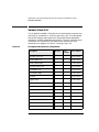
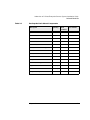
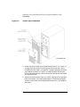
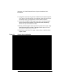
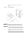
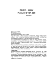
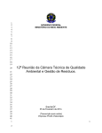
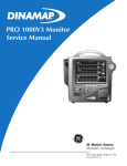
Addendum to D Class Enterprise Servers
Installation and User’s Guide
Third Edition
HP 9000 Series 800t Computers
Manufacturing Part Number: Z7634-96002
February 2000
Communications Infrastructure Computer Operation
© Copyright 2000 Hewlett-Packard Company
Notice
The information contained in this document is subject to change without
notice.
HEWLETT-PACKARD MAKES NO WARRANTY OF ANY KIND WITH
REGARD TO THE MATERIAL, INCLUDING, BUT NOT LIMITED TO
THE IMPLIED WARRANTIES OF MERCHANTABILITY AND
FITNESS FOR A PARTICULAR PURPOSE. Hewlett-Packard shall not
be liable for errors contained herein or for incidental or consequential
damages in connection with the furnishing, performance, or use of this
material.
Hewlett-Packard assumes no responsibility for the use or reliability of its
software on equipment that is not furnished by Hewlett-Packard.
This document contains proprietary information which is protected by
copyright. All rights are reserved. No part of this document may be
photocopied, reproduced, or translated to another language without the
prior written consent of Hewlett-Packard Company.
© Copyright 1997, 1998, 2000 Hewlett-Packard Company
2
Printing History
The Printing History below identifies the edition of this manual and any
updates that are included. Periodically, update packages are distributed
which contain replacement pages to be merged into the manual,
including an updated copy of this printing history page. Also, the update
may contain write-in instructions.
Each reprinting of this manual will incorporate all past updates;
however, no new information will be added. Thus, the reprinted copy will
be identical in content to prior printings of the same edition with its
user-inserted update information. New editions of this manual will
contain new information, as well as all updates.
Printing History
First Edition
May 1997
Second Edition
May 1998
Third Edition
February 2000
About This Manual
The HP 9000 family of products embraces the D Class Enterprise Server
line which includes Series 800t, a NEBS-compatible version. This
document explains how to install the seismic rack and DC power supply
which provide NEBS compatibility for the system.
4
Contents
1. Addendum to D Class Enterprise Servers System Installation
Guide
Contents . . . . . . . . . . . . . . . . . . . . . . . . . . . . . . . . . . . . . . . . . . . . . . . . . . . .8
Purpose of this Addendum . . . . . . . . . . . . . . . . . . . . . . . . . . . . . . . . . . . . .9
Tools Needed . . . . . . . . . . . . . . . . . . . . . . . . . . . . . . . . . . . . . . . . . . . . . . .9
Seismic Rack Kit . . . . . . . . . . . . . . . . . . . . . . . . . . . . . . . . . . . . . . . . . . . .10
Site Hazard Considerations . . . . . . . . . . . . . . . . . . . . . . . . . . . . . . . . . .12
Installation. . . . . . . . . . . . . . . . . . . . . . . . . . . . . . . . . . . . . . . . . . . . . . . . .13
DC Power Supply . . . . . . . . . . . . . . . . . . . . . . . . . . . . . . . . . . . . . . . . . . . .21
Connections. . . . . . . . . . . . . . . . . . . . . . . . . . . . . . . . . . . . . . . . . . . . . . .21
Safety Grounding Procedures . . . . . . . . . . . . . . . . . . . . . . . . . . . . . . . .23
Specifications . . . . . . . . . . . . . . . . . . . . . . . . . . . . . . . . . . . . . . . . . . . . .24
Replacement Power Supply . . . . . . . . . . . . . . . . . . . . . . . . . . . . . . . . . .24
A. Regulatory/Safety Statements
FCC Statement (USA Only) . . . . . . . . . . . . . . . . . . . . . . . . . . . . . . . . . . .26
IEC Statement (Worldwide). . . . . . . . . . . . . . . . . . . . . . . . . . . . . . . . . .26
International . . . . . . . . . . . . . . . . . . . . . . . . . . . . . . . . . . . . . . . . . . . . . . .27
VCCI Class A Statement (Japan Only) . . . . . . . . . . . . . . . . . . . . . . . . .27
Spécification ATI Classe A (France seulement) . . . . . . . . . . . . . . . . . .27
Product Noise Declaration (Germany Only) . . . . . . . . . . . . . . . . . . . . .28
EMC Regulatory . . . . . . . . . . . . . . . . . . . . . . . . . . . . . . . . . . . . . . . . . . . .29
EMC Certification . . . . . . . . . . . . . . . . . . . . . . . . . . . . . . . . . . . . . . . . .29
EMC Labels . . . . . . . . . . . . . . . . . . . . . . . . . . . . . . . . . . . . . . . . . . . . . .29
Safety . . . . . . . . . . . . . . . . . . . . . . . . . . . . . . . . . . . . . . . . . . . . . . . . . . .29
Safety Certification . . . . . . . . . . . . . . . . . . . . . . . . . . . . . . . . . . . . . . .29
Safety Labels . . . . . . . . . . . . . . . . . . . . . . . . . . . . . . . . . . . . . . . . . . . .29
5
Contents
6
1
Addendum to D Class
Enterprise Servers System
Installation Guide
7
Addendum to D Class Enterprise Servers System Installation Guide
Contents
Contents
• Purpose of this Addendum
• Seismic Rack Kit
• Installation
• DC Power Supply
8
Chapter 1
Addendum to D Class Enterprise Servers System Installation Guide
Purpose of this Addendum
Purpose of this Addendum
This addendum provides information and procedures for installation of a
Hewlett-Packard 9000 Series 800t D Class Server in a Central Office. It
provides information about differences between this computer and the
Hewlett-Packard D Class Enterprise Server, and contains the following
procedures not found in the D Class Enterprise Servers System
Installation Guide:
• Earthquake mounting of an HP9000 Series 800t D Class Server in a
Central Office equipment frame
• Connecting DC Power to an HP9000 Series 800t D Class Server
Tools Needed
• Phillips head screw drivers, size # 3 and # 1
• Nut driver (or socket or open-end) size 3/8 in.
• Star-point Torx drivers, size 15 and 25
• Needle-nose pliers
Chapter 1
9
Addendum to D Class Enterprise Servers System Installation Guide
Seismic Rack Kit
Seismic Rack Kit
The HP 9000 Series 800t D Class Server can be fitted with a seismic rack
mount kit for installation in a 19-inch open relay rack. This earthquake
rack fulfills Bellcore requirements for Telecommunication equipment
installed in a NEBS-compatible central office. Table 1-1 shows the parts
included for this installation, and identification numbers for each
component as it appears on Figure 1-1 through Figure 1-6.
Table 1-1
Earthquake Rack-Mount Components
Description
Quantity
Item
Number
Part Number
Assembly, Top Cover
1
1
Z7616-60008
Bracket, Main, Left
1
2
Z7616-00009
Bracket, Main, Right
1
3
Z7616-00010
Assembly, Panel Latch
1
4
Z7616-60005
Bezel Mount, Left
1
5
Z7616-00012
Bezel Mount, Right
1
6
Z7616-00013
Pan, Base
1
7
Z7616-00014
Support, Bezel
1
8
Z7616-00015
Bracket, Rear
2
9
Z7630-00001
Plate, Cover
2
10
Z7630-00016
Assembly, Slide, Left
1
11
Z7616-60003
Assembly, Slide, Right
1
12
Z7616-60004
Weldment, Mounting Tray
1
13
A3262-60024
Assembly, Rack, Bezel
1
14
A3262-60036
Label, Lock
1
15
Z7616-80005
Pan Screw (12-24 x .62”)
20
16
2940-0289
10
Chapter 1
Addendum to D Class Enterprise Servers System Installation Guide
Seismic Rack Kit
Table 1-1
Earthquake Rack-Mount Components
Description
Quantity
Item
Number
Part Number
Split Lock Washer, #12
10
17
2190-0631
Flat Washer, #12
10
18
3050-0103
Screw 10-32 x, 38” Torx Pan
28
19
2680-0281
Flat Washer, #10
8
20
3050-0226
Nut w/lock, 10-32
8
21
2740-0003
Screw, 6-32 thread-forming
3
22
0624-0727
Screw, 6-32 X .38” Pozi flat
4
23
2360-0196
Screw, 12-24 X .38” Pozi flat
6
24
2940-0297
Screw, 6-32 X. 38’ Torx Pan
5
25
C2260-20001
Ass’y, Cable Retractor
1
26
Z7616-60009
Cable Tie, 11" long
10
27
1400-0482
Clip, Bezel Attach
2 + (2 opt)
28
C2786-40002
Screw, M4 x 0.7 X 8 Torx Pan
2 + (2 opt)
29
0515-0433
Receptacle, Clip on
2
30
1390-1090
Chapter 1
11
Addendum to D Class Enterprise Servers System Installation Guide
Seismic Rack Kit
Site Hazard Considerations
Hewlett Packard recommends the following environmental and
mechanical factors for review and compliance prior to installation of
equipment.
85° F Tmra - Manufacturer’s maximum recommended ambient temp.
1. Elevated Operating Ambient Temp. - If installed in a multi-unit
rack assembly, consider air conditioning or ventilation to avoid
exceeding 85° F.
2. Reduced Air Flow - Installation of equipment in a rack should be
such that the amount of air flow required for safe operation is not
compromised.
3. Mechanical Loading - Mounting of equipment in a rack should be
such that no hazard exists due to uneven mechanical loading.
4. Circuit Overloading - Please refer to the note on page 23.
5. Reliable Earthing - Please refer to the topic “Safety Grounding
Procedures” on page 23.
12
Chapter 1
Addendum to D Class Enterprise Servers System Installation Guide
Installation
Installation
Install the seismic rack kit and the HP 9000 Series 800t D Class Server
into an open relay rack using the following steps. References to item
numbers in these steps pertain to the item numbers listed in Table 1-1
on page 10.
1. Unpack the rack-mount kit and check the hardware, using the parts
list in Table 1-1 and the illustrations in this procedure to ensure that
all the required parts are present.
2. Remove the standard front bezel (narrow) that was shipped installed
on the computer. It is hinged at the top and secured by split molded
posts which fit into openings in the metal-work. It can be removed by
pulling outward at the bottom edge and lifting the top edge off the
hinges.
3. Remove the emblem insert and the door from the standard bezel.
These items will be transferred to the wide bezel in a later step.
• The molded plastic emblem insert has three tapered split-post
protrusions on the back, which insert into matching holes on the
cover and spread apart when inserted to provide an interference
fit. A convenient tool for compressing the split retainers is a pair of
needle-nose pliers. Start at one end and push out on the emblem
insert as you compress each split-post retainer from the rear.
• The plastic door is pivoted in each corner on its left edge. Open the
door and flex it carefully, forming a slight bow near the center on
the inside edge, to pop the molded plastic pin on the bezel out of
the molded socket on the bottom of the door. See Figure 1-1 on
page 14.
4. To locate the position within the rack for installing the seismic rack
kit, allow 5/8 in. above the top-most hole in the vertical channels
needed for attaching the main bracket panels. For example, to install
the kit so that the top edge of its front bezel is flush with the bottom
edge of existing equipment in the rack, measure 5/8 in. below that
bottom edge and note the corresponding hole in the vertical channel.
Chapter 1
13
Addendum to D Class Enterprise Servers System Installation Guide
Installation
Figure 1-1
Seismic Rack Installation
D Class Server
5. Attach the right and left main bracket panels (items 2, 3 in Figure 1-2
on page 15) to the vertical mounting rails of the relay rack, using
hardware item 24, Table 1-1 on page 10. The bracket panel is oriented
top to bottom as shown in Figure 1-2. Align the upper counter-sunk
hole on the panel with the hole in the vertical channel that was noted
in the previous step.
6. Attach the rear brackets (Figure 1-2, item 9, 2 places) to the right and
left main brackets, using item 19 hardware in three places as shown.
Attach to rear of relay rack using hardware items 16, 17, and 18 (4 pls
each side).
14
Chapter 1
Addendum to D Class Enterprise Servers System Installation Guide
Installation
7. Assemble base pan (Figure 1-2, item 7) to lower row of holes on main
brackets, but do not tighten the hardware yet. With pan positioned
between the main bracket panels from the rear, raise it to align the
holes as needed. Use item 19 hardware in four places on each bracket.
Use the item 16, 17, 18 hardware to fasten each side of the pan to the
vertical channel (2 pls).
Figure 1-2
Seismic Rack Installation
Chapter 1
15
Addendum to D Class Enterprise Servers System Installation Guide
Installation
8. Using item 16 screws (only) attach the bezel mount brackets (items 5,
6 in Figure 1-3) to the vertical rails as shown. Attach the two clip-on
receptacles (item 30) at the bottom of the brackets as shown.
9. For full GR-63-CORE NEBS compliance, attach only the two bezel
clips at the top of the brackets using item 29 screws. (Optionally
attach two clips at the bottom as well.)
10. Attach the bezel support (item 8) to lower area of vertical rails using
item 16 screws (only) as shown. Top edge of bezel support is flush
with bottom of bezel mount brackets.
11. Position top cover (item 1) in upper area as shown. Install but don’t
tighten screws.
Figure 1-3
Seismic Rack Installation
16
Chapter 1
Addendum to D Class Enterprise Servers System Installation Guide
Installation
12. Attach cable retractor (item 26, Figure 1-3) to right main bracket as
shown.
13. Attach the slide assemblies to the main brackets using the top row of
holes (above the base pan). Do not tighten the hardware (items 20, 21)
yet.
NOTE
These two assemblies are mirror image; ensure that they are oriented as
shown.
14. Position the base pan, installed in step 6, to support the slides by
exerting forceful upward pressure on the base pan; then secure all
fasteners including on the slides.
15. Extend slides until they lock and position the mounting tray (Figure
1-4, item 13) to the front extensions as shown. Engage alignment pins
for proper location and secure with item 19 hardware. Test for proper
installation by sliding to full extent of travel in and out. (Slide release
buttons are on sides of slide channels near front.)
Chapter 1
17
Addendum to D Class Enterprise Servers System Installation Guide
Installation
Figure 1-4
WARNING
Seismic Rack Installation
The HP 9000 D Class Enterprise Server weighs about 49.5 kg
(110 lbs).Use Two people to lift the D Class server cabinet.
16. With tray extended hoist computer into position, aligning base with
locator pins in tray. Slide tray and computer into rack and secure at
three places with thread-forming screws (hardware item 22) at rear of
tray.
17. With the computer positioned into the rack, fasten knurled screws in
latch panel to lower tabs in bezel mount brackets. NOTE: tighten
securely.
18
Chapter 1
Addendum to D Class Enterprise Servers System Installation Guide
Installation
18. Attach the latch panel (item 4) to front of mounting tray using five
screws.
19. With the computer securely engaged within the rack assembly, check
alignment of top cover (refer to Step 10) and tighten all fasteners.
Figure 1-5
Seismic Rack Installation
D Class Server
20. Install the emblem insert and door removed from the standard bezel
(refer to Step 3) onto the wide bezel (Figure 1-6, item 14).
21. Remove handles from the wide bezel and position it onto the bezel
mounts attached to the rack.
22. Apply lock label (item 15) to the front door where shown.
Chapter 1
19
Addendum to D Class Enterprise Servers System Installation Guide
Installation
23. Secure the bezel to the bezel mounts with the cover plates (item 10, 2
places) shown in Figure 1-6.
Figure 1-6
Seismic Rack Installation
24. Route all cables to allow unrestricted movement of the assembly
when sliding in and out. Attach wires to cable retractor (Figure 1-3,
item 26) using cable ties (Figure 1-3, item 27).
20
Chapter 1
Addendum to D Class Enterprise Servers System Installation Guide
DC Power Supply
DC Power Supply
The HP 9000 Series 800t D Class Server contains a NEBS-compatible
direct current (DC) power supply, rather than the alternating current
(AC) power supply furnished with the standard HP 9000 D Class
computer. This switching power supply is designed to work on DC by
replacing the AC input module with a DC-to-DC converter module.
This DC power supply directly replaces the standard AC supply for the
purpose of operating this computer from a telephone central office
negative 48 volt battery or negative 60 volt battery input.
WARNING
A shock hazard exists! Do not attempt to power-up the power
supply system outside the computer system chassis. The power
supply requires a load and other enabling signals to operate
properly.
This DC power option provides a D Class computer server compatible to
NEBS requirements for operation in a Central Office environment where
equipment is powered from 48VDC batteries.
The power supply also provides alarm outputs in the form of relay
contact closures to indicate a power supply failure. An additional feature
provides a remote control input, which can be used to turn off the power
supply for the purposes of resetting the computer system.
Connections
The DC Power Supply comes with a 9-pin Universal Mate-N-Lock
connector for power, alarm, and control circuits. A mating 9-pin plug
with a 15-foot cable is supplied with the unit. The other end of the cable
is bare wire to be connected to the battery plant on the site.
CAUTION
The power wire assembly has been evaluated for use as internal wire
only and therefore needs to be installed in a cabinet for the system to
retain its safety regulatory markings.
Chapter 1
21
Addendum to D Class Enterprise Servers System Installation Guide
DC Power Supply
Table 1-2 shows the pinouts for the site end of this cable. Figure 1-5
shows a diagram of the pins. The user/installer must make connections
to the site installation using this information. Connect the 9-pin
connector on the supplied cable to the negative 48/60 volt power supply
at the rear of the system chassis.
Table 1-2
DC Power Cable Pinouts
Function
Color
Pin No
-48V (14 AWG)
Black
1
Power Supply Status (Open-OK)
White
2
Shield
WARNING
3
-48V (14 AWG)
Black
4
Fan Status (Open-OK
Red
5
Alarm Common
Green
6
-48V RTN (14 AWG)
Red
7
-48V RTN (14 AWG)
Red
8
Remote Reset (Close-reset)
Black
9
1.) The power supply cable is used as the main disconnect device
for this equipment. The key switch on front of SPU does NOT
disconnect the input to power supply.
2.) Make sure that all central office safety precautions are
carefully observed when connecting the power supply to
primary power source.
3.) This product is to be installed only in Restricted Access Areas
(dedicated equipment rooms, equipment closets or the like) in
accordance with Articles 110-16 to 110-18 of National Electrical
Code, ANSI/NFFA 70.
22
Chapter 1
Addendum to D Class Enterprise Servers System Installation Guide
DC Power Supply
NOTE
To protect the equipment from overload or short circuits that may cause
equipment damage or fire, the power supply is fused internally. For
added safety and integrity in the Central Office, the circuit which
connects to power supply should be protected with a 30 Amp over-current
fuse.
Figure 1-7
DC Power Cable Pin Diagram
1
2
3
4
5
6
7
8
9
Front
Safety Grounding Procedures
Connect an earth ground cable to the grounding stud provided on the
power supply chassis. Attach the cable to the stud using the lockwasher
and nut provided. Preferably use at least a 10 AWG cable with a round
eyelet crimp-lug.
WARNING
The computer system should at all times be connected to chassis
ground. The stud has been provided near the input power
connector for this purpose. Failure to connect an earth ground
wire to the ground stud on the computer system will in essence
leave the chassis floating, which could be hazardous to an
operator because of the potential of electric shock.
Chapter 1
23
Addendum to D Class Enterprise Servers System Installation Guide
DC Power Supply
Specifications
Table 1-3
DC Power Specifications
Specification
Data
Input
-48V, 20A max under full load
-60V
Shutdown Thresholds
-72V (input over-voltage)
-40V (input under-voltage)
Power
650W
Outputs (* = remote sense provided)
3.3V*, 25A (maximum)
5V*, 55A (maximum)
12.V, 10A (maximum)
Aux5V, 55A (maximum)
Temperature Ranges:
5° to 40° C (41° to 104° F)
Operating:
-40° to 45°C (-40° to 113°F)
Non-operating:
-5° to 50°C (23° to 122°F)
Short-term Operating:
Remote (switched ground) RESET signal:
-48V, 50mA (minimum)
500mA (maximum)
Alarm signals:
Input out of tolerance
Output out of tolerance
Dry relay contact closure
for all alarms
Fused circuits:
Power Input
(Not field replaceable)
30A
Replacement Power Supply
To order a replacement DC Power Supply, order replacement part
number Z7634-67003.
24
Chapter 1
A
Regulatory/Safety Statements
25
Regulatory/Safety Statements
FCC Statement (USA Only)
FCC Statement (USA Only)
The Federal Communications Commission (in 47 CFR 15.105) has
specified that the following notice be brought to the attention of the users
of this product.
This equipment has been tested and found to comply with the limits for a
Class A digital device, pursuant to Part 15 of the FCC Rules. These
limits are designed to provide reasonable protection against harmful
interference when the equipment is operated in a commercial
environment. This equipment generates, uses, and can radiate radio
frequency energy and, if not installed and used in accordance with the
instruction manual, may cause harmful interference to radio
communications. Operation of this equipment in a residential area is
likely to cause harmful interference in which case the user will be
required to correct the interference at his own expense. The end user of
this product should be aware that any changes or modifications made to
this equipment without the approval of Hewlett-Packard could result in
the product not meeting the Class A limits, in which case the FCC could
void the user's authority to operate the equipment.
IEC Statement (Worldwide)
This is a Class A product. In a domestic environment this product may
cause radio interference in which case the user may be required to take
adequate measures.
26
Appendix A
Regulatory/Safety Statements
International
International
VCCI Class A Statement (Japan Only)
Spécification ATI Classe A (France seulement)
DECLARATION D'INSTALLATION ET DE MISE EN EXPLOITATION
d'un matériel de traitement de l'information (ATI), classé A en fonction
des niveaux de perturbations radioélectriques émis, définis dans la
norme européenne EN 55022 concernant la Compatibilité
Electromagnétique.
Cher Client,
Conformément à la Réglementation Française en vigueur l'installation
ou le transfert d'installation, et l'exploitation de cet appareil de classe A,
doivent faire l'objet d'une déclaration (en deux exemplaires)
simultanément auprès des services suivants:
Comité de Coordination des Télécommunications 20, avenue de Ségur - 75700
PARIS
Préfecture du département du lieu d'exploitation
Le formulaire à utiliser est disponible auprès des préfectures.
La déclaration doit être faite dans les 30 jours suivant la mise en
exploitation.
Le non respect de cette obligation peut être sanctionné par les peines
prévues au code des Postes et Télécommunications et celles indiquées
dans la loi du 31 mai 1993 susvisée.
Appendix A
27
Regulatory/Safety Statements
International
Arrêté du 27 Mars 1993, publié au J.O. du 28 Mars - ATI
Product Noise Declaration (Germany Only)
Acoustic Noise Emissions
LpA: 57 dB
At bystander position per ISO 7779.
All data are the results from type tests of the product configuration
having the highest acoustic emissions: 8 disk drives.
All other configurations have lower emission levels.
Refer to the environmental specification section of the manual for
details.
Geräuschemission
LpA: 57 dB
Am fiktiven Arbeitsplatz nach DIN 45635 T. 19.
Die Daten sind die Ergebnisse von Typprüfungen an
Gerätekonfigurationen mit den höchsten Geräuschemissionen: 8
Plattenlaufwerke.
Alle andere Konfigurationen haben geringere Geräuschpegel.
Für weitere Angaben siehe unter Umgebungsbedingungen.
28
Appendix A
Regulatory/Safety Statements
EMC Regulatory
EMC Regulatory
EMC Certification
prEN 55024-2
prEN 55024-3
prEN 55024-4
For USA, FCC Class A, part 15
For Europe, CISPR-22 Level A
For Japan, VCCI Class A
EMC Labels
CE MarkFCC Statement
Canadian EMC Statement
Japanese VCCI Statement
Safety
Safety Certification
UL 1950, 2nd Edition
CSA 22.2 No. 950-93
IEC 950, 1991 2nd Edition Am. 1 and Am. 2
EMOKO-TUE (74) DK203
TUV EN60950 1992, 2nd Edition
SS-EN 60950 & EMKO-TSE (74-SEC)203.93
SSIFS 1980:2 or SS-EN 60825
EN 60950 1992, 2nd Edition Am. 1 and Am. 2
Safety Labels
UL Mark listed
UL Mark recognized for component
CSA Mark
TUV/GS Mark
Appendix A
29
Regulatory/Safety Statements
EMC Regulatory
DECLARATION OF CONFORMITY
according to ISO/IEC Guide 22 and EN 45104
Manufacturer’s Name:
Hewlett-Packard Company
Manufacturer’s Address:
8000 Foothills Blvd.
Roseville, CA 95747, USA
declares that the product:
Product Name:
PA-RISC Computer System
Model Numbers:
HP 9000, Models Dxyz (x, y, z is any number 0-9)
and Z76xy (x, y is any number from 0 to 9)
Product Options:
All
conforms to the following Product Specifications:
Safety:
IEC950:1991+ A1, A2, A3 / EN 60950:1992 + A1,A2, A3
GR-63-CORE:1995, Seismic Zone 4
EMC:
CISPR 22:1993/EN 55022:1994 - Class A2
EN 50082-1:1992
IEC 801-2:1991/prEN 55024-2:1992 4 kV CD, 8kV AD
IEC 801-3:1984/prEN 55024-3:1991 3 V/m
IEC 801-4:1988/pr EN55024-4:1992 0.5 kV Signal Lines
1 kV Power Lines
Supplementary Information:
The product herewith complies with the requirements of the Low Voltage Directive
73/23/EEC and the EMC Directive 89/336/EEC and carries the CE marking accordingly.
1) Product models where y is equal to 0 through 5 meet the EMC directive as attested to in Certificate
Number RFI/CBC1/3397A.
2) The product was tested in a typical configuration with Hewlett-Packard computer peripherals.
Roseville, June 25, 1997
_________________________________
Frank Dembski, Quality Manager
European Contact:Your local Hewlett-Packard Sales/Service Office or Hewlett-Packard GmbH,
Department TRE, Herrenberger Strasse 130, D-71034 Boblingen, Germany (FAX: + 49-7031-14-3143)
30
Appendix A