1
HP OpenView Storage Data Protector
Administrator’s Guide
Manual Edition: May 2003
Manufacturing Part Number: B6960-90078
Release A.05.10
© Copyright Hewlett-Packard Development Company, L.P.2003.
Legal Notices
Hewlett-Packard makes no warranty of any kind with regard to this
manual, including, but not limited to, the implied warranties of
merchantability and fitness for a particular purpose. Hewlett-Packard
shall not be held liable for errors contained herein or direct, indirect,
special, incidental or consequential damages in connection with the
furnishing, performance, or use of this material.
Warranty. A copy of the specific warranty terms applicable to your
Hewlett-Packard product and replacement parts can be obtained from
your local Sales and Service Office.
Restricted Rights Legend. All rights are reserved. No part of this
document may be photocopied, reproduced, or translated to another
language without the prior written consent of Hewlett-Packard
Company. The information contained in this document is subject to
change without notice.
Use, duplication or disclosure by the U.S. Government is subject to
restrictions as set forth in subparagraph (c) (1) (ii) of the Rights in
Technical Data and Computer Software clause at DFARS 252.227-7013
for DOD agencies, and subparagraphs (c) (1) and (c) (2) of the
Commercial Computer Software Restricted Rights clause at FAR 52.22719 for other agencies.
Hewlett-Packard Company
United States of America
Copyright Notices. ©Copyright 1983-2003 Hewlett-Packard
Development Company, L.P. all rights reserved.
Reproduction, adaptation, or translation of this document without prior
written permission is prohibited, except as allowed under the copyright
laws.
©Copyright 1979, 1980, 1983, 1985-93 Regents of the University of
California
This software is based in part on the Fourth Berkeley Software
Distribution under license from the Regents of the University of
California.
©Copyright 1986-1992 Sun Microsystems, Inc.
ii
©Copyright 1985-86, 1988 Massachusetts Institute of Technology
©Copyright 1989-93 The Open Software Foundation, Inc.
©Copyright 1986-1997 FTP Software, Inc. All rights reserved
©Copyright 1986 Digital Equipment Corporation
©Copyright 1990 Motorola, Inc.
©Copyright 1990, 1991, 1992 Cornell University
©Copyright 1989-1991 The University of Maryland
©Copyright 1988 Carnegie Mellon University
©Copyright 1991-1995 by Stichting Mathematisch Centrum,
Amsterdam, The Netherlands
©Copyright 1999, 2000 Bo Branten
Trademark Notices. UNIX® is a registered trademark in the United
States and other countries, licensed exclusively through X/Open
Company Limited.
X Window System is a trademark of the Massachusetts Institute of
Technology.
Motif is a trademark of the Open Software Foundation, Inc. in the U.S.
and other countries.
Windows NT™ is a U.S. trademark of Microsoft Corporation. Microsoft®,
MS-DOS®, Windows® and MS Windows® are U.S. registered
trademarks of Microsoft Corporation.
Oracle®, SQL*Net®, and Net8® are registered U.S. trademarks of
Oracle Corporation, Redwood City, California. Oracle Reports™,
Oracle8™, Oracle8 Server Manager™ and Oracle8 Recovery Manager™
are trademarks of Oracle Corporation, Redwood City, California.
Java™ is a U.S. trademark of Sun Microsystems, Inc.
Adobe® and Acrobat® are trademarks of Adobe Systems Incorporated.
ARM® is a registered trademark of ARM Limited.
X/Open® is a registered trademark, and the X device is a trademark of X/
Open Company Ltd. in the UK and other countries.
VisiCalc® is a U.S. registered trademark of Lotus Development Corp.
iii
HP-UX Release 11.00 and later (in both 32- and 64-bit configurations) on
all HP 9000 computers are Open Group UNIX 95 branded products.
Netscape and Netscape Navigator are U.S. trademarks of Netscape
Communications Corporation.
OpenView® is a registered U.S. trademark of Hewlett-Packard
Company.
© 2003 Bristol Technology, Inc., Bristol Technology, Wind/U, HyperHelp
and Xprinter are registered trademarks of Bristol Technology Inc.
Other reserved names are trademarks of the respective companies.
iv
Contents
1. Introducing Data Protector
In This Chapter . . . . . . . . . . . . . . . . . . . . . . . . . . . . . . . . . . . . . . . . . . . . . . . . . . . . . . . . . 2
The Data Protector Cell Environment . . . . . . . . . . . . . . . . . . . . . . . . . . . . . . . . . . . . . . . 3
How a Backup Session Works . . . . . . . . . . . . . . . . . . . . . . . . . . . . . . . . . . . . . . . . . . . . 4
How a Restore Session Works . . . . . . . . . . . . . . . . . . . . . . . . . . . . . . . . . . . . . . . . . . . . 4
Using the Data Protector User Interface . . . . . . . . . . . . . . . . . . . . . . . . . . . . . . . . . . . . . 6
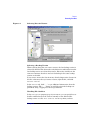
Graphical User Interface . . . . . . . . . . . . . . . . . . . . . . . . . . . . . . . . . . . . . . . . . . . . . . . . 7
The Command-Line Interface . . . . . . . . . . . . . . . . . . . . . . . . . . . . . . . . . . . . . . . . . . . 11
Data Protector Online Resources . . . . . . . . . . . . . . . . . . . . . . . . . . . . . . . . . . . . . . . . . 12
Using Microsoft Management Console (MMC) . . . . . . . . . . . . . . . . . . . . . . . . . . . . . . 13
Overview of Tasks to Set Up Data Protector . . . . . . . . . . . . . . . . . . . . . . . . . . . . . . . . . 15
2. Configuring and Using Backup Devices
In This Chapter . . . . . . . . . . . . . . . . . . . . . . . . . . . . . . . . . . . . . . . . . . . . . . . . . . . . . . . .
Configuring Backup Devices . . . . . . . . . . . . . . . . . . . . . . . . . . . . . . . . . . . . . . . . . . . . . .
Configuring Standalone Devices . . . . . . . . . . . . . . . . . . . . . . . . . . . . . . . . . . . . . . . . . . .
Configuring File Devices . . . . . . . . . . . . . . . . . . . . . . . . . . . . . . . . . . . . . . . . . . . . . . . . .
Configuring Library Devices . . . . . . . . . . . . . . . . . . . . . . . . . . . . . . . . . . . . . . . . . . . . . .
Configuring Libraries with Multiple Systems . . . . . . . . . . . . . . . . . . . . . . . . . . . . . . . .
Configuring Magazine Devices . . . . . . . . . . . . . . . . . . . . . . . . . . . . . . . . . . . . . . . . . . . .
Configuring Stacker Devices . . . . . . . . . . . . . . . . . . . . . . . . . . . . . . . . . . . . . . . . . . . . . .
Configuring a Library for Mixed Media . . . . . . . . . . . . . . . . . . . . . . . . . . . . . . . . . . . . .
Configuring Devices for Direct Backup. . . . . . . . . . . . . . . . . . . . . . . . . . . . . . . . . . . . . .
Configuration Procedure . . . . . . . . . . . . . . . . . . . . . . . . . . . . . . . . . . . . . . . . . . . . . . .
Support of New Devices . . . . . . . . . . . . . . . . . . . . . . . . . . . . . . . . . . . . . . . . . . . . . . . . . .
Using Several Drive Types in a Library . . . . . . . . . . . . . . . . . . . . . . . . . . . . . . . . . . . . .
Shared Devices in the SAN Environment . . . . . . . . . . . . . . . . . . . . . . . . . . . . . . . . . . .
Locking Devices Used Exclusively by Data Protector . . . . . . . . . . . . . . . . . . . . . . . .
Locking Devices Used by Multiple Applications . . . . . . . . . . . . . . . . . . . . . . . . . . . . .
Direct Library Access Concept . . . . . . . . . . . . . . . . . . . . . . . . . . . . . . . . . . . . . . . . . . .
Indirect Library Access Concept . . . . . . . . . . . . . . . . . . . . . . . . . . . . . . . . . . . . . . . . .
Configuration Overview . . . . . . . . . . . . . . . . . . . . . . . . . . . . . . . . . . . . . . . . . . . . . . . .
Shared Devices and MC/ServiceGuard . . . . . . . . . . . . . . . . . . . . . . . . . . . . . . . . . . . .
Drive Cleaning . . . . . . . . . . . . . . . . . . . . . . . . . . . . . . . . . . . . . . . . . . . . . . . . . . . . . . . . .
Configuring Automatic Drive Cleaning . . . . . . . . . . . . . . . . . . . . . . . . . . . . . . . . . . . .
Testing the Drive Cleaning Configuration . . . . . . . . . . . . . . . . . . . . . . . . . . . . . . . . .
Busy Drive Handling . . . . . . . . . . . . . . . . . . . . . . . . . . . . . . . . . . . . . . . . . . . . . . . . . . . .
Activating Barcode Support . . . . . . . . . . . . . . . . . . . . . . . . . . . . . . . . . . . . . . . . . . . . . .
18
20
23
26
29
32
34
35
37
38
39
41
42
44
46
46
47
47
47
58
61
62
63
65
66
v
Contents
Activating Cartridge Memory Support . . . . . . . . . . . . . . . . . . . . . . . . . . . . . . . . . . . . . .
Disabling a Backup Device . . . . . . . . . . . . . . . . . . . . . . . . . . . . . . . . . . . . . . . . . . . . . . .
Removing a Backup Device . . . . . . . . . . . . . . . . . . . . . . . . . . . . . . . . . . . . . . . . . . . . . .
Renaming a Backup Device . . . . . . . . . . . . . . . . . . . . . . . . . . . . . . . . . . . . . . . . . . . . . . .
Device Locking . . . . . . . . . . . . . . . . . . . . . . . . . . . . . . . . . . . . . . . . . . . . . . . . . . . . . . . . .
Device Concurrency, Segment Size, and Block Size . . . . . . . . . . . . . . . . . . . . . . . . . . . .
68
70
72
73
74
76
3. Configuring Users and User Groups
In This Chapter . . . . . . . . . . . . . . . . . . . . . . . . . . . . . . . . . . . . . . . . . . . . . . . . . . . . . . . .
Data Protector User Rights . . . . . . . . . . . . . . . . . . . . . . . . . . . . . . . . . . . . . . . . . . . . . . .
Predefined Data Protector User Groups. . . . . . . . . . . . . . . . . . . . . . . . . . . . . . . . . . . . .
Adding or Deleting a User Group . . . . . . . . . . . . . . . . . . . . . . . . . . . . . . . . . . . . . . . . . .
Adding a User Group . . . . . . . . . . . . . . . . . . . . . . . . . . . . . . . . . . . . . . . . . . . . . . . . . .
Deleting a User Group . . . . . . . . . . . . . . . . . . . . . . . . . . . . . . . . . . . . . . . . . . . . . . . . .
Adding or Deleting a User . . . . . . . . . . . . . . . . . . . . . . . . . . . . . . . . . . . . . . . . . . . . . . . .
Modifying a User . . . . . . . . . . . . . . . . . . . . . . . . . . . . . . . . . . . . . . . . . . . . . . . . . . . . . . .
Changing User Properties . . . . . . . . . . . . . . . . . . . . . . . . . . . . . . . . . . . . . . . . . . . . . .
Moving a User to Another User Group . . . . . . . . . . . . . . . . . . . . . . . . . . . . . . . . . . . .
Changing User Group Rights . . . . . . . . . . . . . . . . . . . . . . . . . . . . . . . . . . . . . . . . . . . . .
Example User Configurations . . . . . . . . . . . . . . . . . . . . . . . . . . . . . . . . . . . . . . . . . . . . .
Allowing Users to Restore Their Own Files . . . . . . . . . . . . . . . . . . . . . . . . . . . . . . . .
Enabling Users to Back Up Their Systems . . . . . . . . . . . . . . . . . . . . . . . . . . . . . . . . .
82
83
86
88
88
89
90
92
92
92
93
94
94
94
4. Managing Media
In This Chapter . . . . . . . . . . . . . . . . . . . . . . . . . . . . . . . . . . . . . . . . . . . . . . . . . . . . . . . . 98
Overview of Data Protector Media Management . . . . . . . . . . . . . . . . . . . . . . . . . . . . . . 99
Media Life Cycle . . . . . . . . . . . . . . . . . . . . . . . . . . . . . . . . . . . . . . . . . . . . . . . . . . . . . 100
Creating a Media Pool . . . . . . . . . . . . . . . . . . . . . . . . . . . . . . . . . . . . . . . . . . . . . . . . . . 102
Properties of a Media Pool . . . . . . . . . . . . . . . . . . . . . . . . . . . . . . . . . . . . . . . . . . . . . 103
Adding Media to a Media Pool. . . . . . . . . . . . . . . . . . . . . . . . . . . . . . . . . . . . . . . . . . . . 107
Formatting Media . . . . . . . . . . . . . . . . . . . . . . . . . . . . . . . . . . . . . . . . . . . . . . . . . . . . . 108
Formatting Media in a Magazine. . . . . . . . . . . . . . . . . . . . . . . . . . . . . . . . . . . . . . . . 110
Recognizing Other Data Formats . . . . . . . . . . . . . . . . . . . . . . . . . . . . . . . . . . . . . . . 111
Importing Media . . . . . . . . . . . . . . . . . . . . . . . . . . . . . . . . . . . . . . . . . . . . . . . . . . . . . . 113
Importing the Catalog from Media . . . . . . . . . . . . . . . . . . . . . . . . . . . . . . . . . . . . . . 114
Importing Media in a Magazine Device. . . . . . . . . . . . . . . . . . . . . . . . . . . . . . . . . . . 115
Appending Backups to Media . . . . . . . . . . . . . . . . . . . . . . . . . . . . . . . . . . . . . . . . . . . . 117
Using a Pre-Allocation List of Media for Backup . . . . . . . . . . . . . . . . . . . . . . . . . . . . . 119
vi
Contents
Selecting Media for Backup . . . . . . . . . . . . . . . . . . . . . . . . . . . . . . . . . . . . . . . . . . . . . .
Media Selection . . . . . . . . . . . . . . . . . . . . . . . . . . . . . . . . . . . . . . . . . . . . . . . . . . . . . .
Setting Data Protection for Media . . . . . . . . . . . . . . . . . . . . . . . . . . . . . . . . . . . . . . . .
Recycling Media . . . . . . . . . . . . . . . . . . . . . . . . . . . . . . . . . . . . . . . . . . . . . . . . . . . . . .
Moving Media to Another Pool . . . . . . . . . . . . . . . . . . . . . . . . . . . . . . . . . . . . . . . . . . .
Exporting Media from Data Protector . . . . . . . . . . . . . . . . . . . . . . . . . . . . . . . . . . . . .
Modifying Media Locations . . . . . . . . . . . . . . . . . . . . . . . . . . . . . . . . . . . . . . . . . . . . . .
Modifying Media Descriptions. . . . . . . . . . . . . . . . . . . . . . . . . . . . . . . . . . . . . . . . . . . .
Verifying Data on a Medium . . . . . . . . . . . . . . . . . . . . . . . . . . . . . . . . . . . . . . . . . . . . .
Scanning Media in a Device . . . . . . . . . . . . . . . . . . . . . . . . . . . . . . . . . . . . . . . . . . . . .
Checking the Condition of a Medium . . . . . . . . . . . . . . . . . . . . . . . . . . . . . . . . . . . . . .
Factors Influencing the Condition of Media . . . . . . . . . . . . . . . . . . . . . . . . . . . . . . .
Changing How Media Condition Is Calculated . . . . . . . . . . . . . . . . . . . . . . . . . . . . .
Searching for and Selecting a Medium . . . . . . . . . . . . . . . . . . . . . . . . . . . . . . . . . . . . .
Entering a Medium into a Device . . . . . . . . . . . . . . . . . . . . . . . . . . . . . . . . . . . . . . . . .
Ejecting a Medium from a Device . . . . . . . . . . . . . . . . . . . . . . . . . . . . . . . . . . . . . . . . .
Scheduled Eject of Media . . . . . . . . . . . . . . . . . . . . . . . . . . . . . . . . . . . . . . . . . . . . . .
Vaulting Media . . . . . . . . . . . . . . . . . . . . . . . . . . . . . . . . . . . . . . . . . . . . . . . . . . . . . . . .
Configuring Vaults . . . . . . . . . . . . . . . . . . . . . . . . . . . . . . . . . . . . . . . . . . . . . . . . . . .
Moving Media to a Vault . . . . . . . . . . . . . . . . . . . . . . . . . . . . . . . . . . . . . . . . . . . . . .
Restoring from Media in a Vault . . . . . . . . . . . . . . . . . . . . . . . . . . . . . . . . . . . . . . . .
Copying Media . . . . . . . . . . . . . . . . . . . . . . . . . . . . . . . . . . . . . . . . . . . . . . . . . . . . . . . .
Automated Media Copying . . . . . . . . . . . . . . . . . . . . . . . . . . . . . . . . . . . . . . . . . . . . .
Detection of Write-Protected Media . . . . . . . . . . . . . . . . . . . . . . . . . . . . . . . . . . . . . . .
Using Different Media Format Types . . . . . . . . . . . . . . . . . . . . . . . . . . . . . . . . . . . . . .
Modifying Views in the Media Management Window . . . . . . . . . . . . . . . . . . . . . . . . .
120
120
122
123
124
125
126
127
128
129
131
132
134
135
136
137
138
140
141
141
141
143
145
147
148
149
5. Backup
In This Chapter . . . . . . . . . . . . . . . . . . . . . . . . . . . . . . . . . . . . . . . . . . . . . . . . . . . . . . .
Configuring a Backup . . . . . . . . . . . . . . . . . . . . . . . . . . . . . . . . . . . . . . . . . . . . . . . . . .
Creating a Backup Specification . . . . . . . . . . . . . . . . . . . . . . . . . . . . . . . . . . . . . . . .
Backing Up UNIX Systems . . . . . . . . . . . . . . . . . . . . . . . . . . . . . . . . . . . . . . . . . . . . . .
Backing Up UNIX Filesystems . . . . . . . . . . . . . . . . . . . . . . . . . . . . . . . . . . . . . . . . .
Backing Up Clients Using Disk Discovery . . . . . . . . . . . . . . . . . . . . . . . . . . . . . . . .
Backing Up Disks Using NFS . . . . . . . . . . . . . . . . . . . . . . . . . . . . . . . . . . . . . . . . . .
Backing Up UNIX Disks as Disk Image Objects . . . . . . . . . . . . . . . . . . . . . . . . . . .
Backing Up Windows Systems . . . . . . . . . . . . . . . . . . . . . . . . . . . . . . . . . . . . . . . . . . .
Backing Up Filesystems (Logical Disk Drives) . . . . . . . . . . . . . . . . . . . . . . . . . . . . .
152
153
154
161
161
163
164
166
168
168
vii
Contents
Backing Up CONFIGURATION . . . . . . . . . . . . . . . . . . . . . . . . . . . . . . . . . . . . . . . .
Backing Up Windows Clients Using Disk Discovery . . . . . . . . . . . . . . . . . . . . . . . .
Backing Up Windows Shared Disks . . . . . . . . . . . . . . . . . . . . . . . . . . . . . . . . . . . . .
Backing Up Windows Disks as Disk Image Objects . . . . . . . . . . . . . . . . . . . . . . . . .
Backing Up Novell NetWare Systems. . . . . . . . . . . . . . . . . . . . . . . . . . . . . . . . . . . . . .
Backing Up Novell NetWare Filesystems (Volumes) . . . . . . . . . . . . . . . . . . . . . . . .
Client Backup with Disk Discovery . . . . . . . . . . . . . . . . . . . . . . . . . . . . . . . . . . . . . .
Backing Up NetWare Directory Services (NDS) . . . . . . . . . . . . . . . . . . . . . . . . . . .
Backing Up OpenVMS Systems . . . . . . . . . . . . . . . . . . . . . . . . . . . . . . . . . . . . . . . . . .
Backing Up OpenVMS Filesystems . . . . . . . . . . . . . . . . . . . . . . . . . . . . . . . . . . . . . .
Backing Up in a Direct Backup Environment . . . . . . . . . . . . . . . . . . . . . . . . . . . . . . .
Backup Specification Configuration Procedure . . . . . . . . . . . . . . . . . . . . . . . . . . . .
Starting Direct Backup Using the CLI . . . . . . . . . . . . . . . . . . . . . . . . . . . . . . . . . . .
Scheduling Unattended Backups . . . . . . . . . . . . . . . . . . . . . . . . . . . . . . . . . . . . . . . . .
Starting Backups on Specific Dates. . . . . . . . . . . . . . . . . . . . . . . . . . . . . . . . . . . . . .
Starting Periodic Backups . . . . . . . . . . . . . . . . . . . . . . . . . . . . . . . . . . . . . . . . . . . . .
Editing Your Backup Schedule. . . . . . . . . . . . . . . . . . . . . . . . . . . . . . . . . . . . . . . . . .
Skipping Backups During Holidays. . . . . . . . . . . . . . . . . . . . . . . . . . . . . . . . . . . . . .
Configuring Backup Options When Scheduling Backups . . . . . . . . . . . . . . . . . . . .
Running Consecutive Backups. . . . . . . . . . . . . . . . . . . . . . . . . . . . . . . . . . . . . . . . . .
Selecting a Backup Type: Full or Incremental . . . . . . . . . . . . . . . . . . . . . . . . . . . . . . .
Using Backup Templates . . . . . . . . . . . . . . . . . . . . . . . . . . . . . . . . . . . . . . . . . . . . . . .
Data Protector Default Backup Templates . . . . . . . . . . . . . . . . . . . . . . . . . . . . . . . .
Options Offered by Templates . . . . . . . . . . . . . . . . . . . . . . . . . . . . . . . . . . . . . . . . . .
Using a Backup Template When Creating a New Backup Specification. . . . . . . . .
Applying a Backup Template . . . . . . . . . . . . . . . . . . . . . . . . . . . . . . . . . . . . . . . . . . .
Creating a New Template. . . . . . . . . . . . . . . . . . . . . . . . . . . . . . . . . . . . . . . . . . . . . .
Modifying an Existing Template . . . . . . . . . . . . . . . . . . . . . . . . . . . . . . . . . . . . . . . .
Groups of Backup Specifications . . . . . . . . . . . . . . . . . . . . . . . . . . . . . . . . . . . . . . . . . .
Using Backup Options . . . . . . . . . . . . . . . . . . . . . . . . . . . . . . . . . . . . . . . . . . . . . . . . . .
Most Frequently Used Backup Options. . . . . . . . . . . . . . . . . . . . . . . . . . . . . . . . . . .
List of Data Protector Backup Options . . . . . . . . . . . . . . . . . . . . . . . . . . . . . . . . . . .
Device Backup Options. . . . . . . . . . . . . . . . . . . . . . . . . . . . . . . . . . . . . . . . . . . . . . . .
Pre- and Post-Exec Commands . . . . . . . . . . . . . . . . . . . . . . . . . . . . . . . . . . . . . . . . . . .
Pre- and Post- Exec Commands on Windows Systems . . . . . . . . . . . . . . . . . . . . . . .
Pre- and Post- Exec Commands on UNIX Systems . . . . . . . . . . . . . . . . . . . . . . . . .
Managing Failed Backups . . . . . . . . . . . . . . . . . . . . . . . . . . . . . . . . . . . . . . . . . . . . . . .
Warnings When Backing Up System Disks . . . . . . . . . . . . . . . . . . . . . . . . . . . . . . .
viii
173
183
185
190
194
194
198
199
201
201
204
205
206
207
209
209
210
211
211
212
213
216
216
216
218
218
220
220
222
225
227
236
249
250
251
257
263
263
Contents
Preventing Backup Failure . . . . . . . . . . . . . . . . . . . . . . . . . . . . . . . . . . . . . . . . . . . . 264
Restarting Failed Backups . . . . . . . . . . . . . . . . . . . . . . . . . . . . . . . . . . . . . . . . . . . . . 266
6. Restore
In This Chapter . . . . . . . . . . . . . . . . . . . . . . . . . . . . . . . . . . . . . . . . . . . . . . . . . . . . . . .
Restoring Your Data. . . . . . . . . . . . . . . . . . . . . . . . . . . . . . . . . . . . . . . . . . . . . . . . . . . .
Standard Restore Procedure . . . . . . . . . . . . . . . . . . . . . . . . . . . . . . . . . . . . . . . . . . .
Restoring Disk Images . . . . . . . . . . . . . . . . . . . . . . . . . . . . . . . . . . . . . . . . . . . . . . . .
Restoring Your Data to a Shared Disk . . . . . . . . . . . . . . . . . . . . . . . . . . . . . . . . . . .
Restoring UNIX Systems. . . . . . . . . . . . . . . . . . . . . . . . . . . . . . . . . . . . . . . . . . . . . . . .
Restoring Windows Systems . . . . . . . . . . . . . . . . . . . . . . . . . . . . . . . . . . . . . . . . . . . . .
Restoring the Windows CONFIGURATION . . . . . . . . . . . . . . . . . . . . . . . . . . . . . . .
Restoring the Windows 2000/XP/Server 2003 System State . . . . . . . . . . . . . . . . . .
Restoring the Windows Registry . . . . . . . . . . . . . . . . . . . . . . . . . . . . . . . . . . . . . . . .
Restoring Windows 2000/XP/Server 2003 Services . . . . . . . . . . . . . . . . . . . . . . . . .
Restoring DFS . . . . . . . . . . . . . . . . . . . . . . . . . . . . . . . . . . . . . . . . . . . . . . . . . . . . . . .
Restoring Windows User Profiles and Event Logs . . . . . . . . . . . . . . . . . . . . . . . . . .
Restoring Windows TCP/ IP Services . . . . . . . . . . . . . . . . . . . . . . . . . . . . . . . . . . . .
Restoring Novell Netware Filesystems. . . . . . . . . . . . . . . . . . . . . . . . . . . . . . . . . . . . .
Restoring Namespace Information and Volume Space Restrictions . . . . . . . . . . . .
Restoring File Ownerships and Trustees . . . . . . . . . . . . . . . . . . . . . . . . . . . . . . . . .
Restoring the Novell NetWare CONFIGURATION . . . . . . . . . . . . . . . . . . . . . . . . .
Restoring Novell NDS. . . . . . . . . . . . . . . . . . . . . . . . . . . . . . . . . . . . . . . . . . . . . . . . .
Restoring OpenVMS Filesystems . . . . . . . . . . . . . . . . . . . . . . . . . . . . . . . . . . . . . . . . .
What is Restored? . . . . . . . . . . . . . . . . . . . . . . . . . . . . . . . . . . . . . . . . . . . . . . . . . . . .
Restore Options . . . . . . . . . . . . . . . . . . . . . . . . . . . . . . . . . . . . . . . . . . . . . . . . . . . . . . .
List of Restore Options . . . . . . . . . . . . . . . . . . . . . . . . . . . . . . . . . . . . . . . . . . . . . . . .
Restore Techniques . . . . . . . . . . . . . . . . . . . . . . . . . . . . . . . . . . . . . . . . . . . . . . . . . . . .
Restoring Files to Different Paths . . . . . . . . . . . . . . . . . . . . . . . . . . . . . . . . . . . . . . .
Restoring Files in Parallel . . . . . . . . . . . . . . . . . . . . . . . . . . . . . . . . . . . . . . . . . . . . .
Viewing Files Not in the IDB . . . . . . . . . . . . . . . . . . . . . . . . . . . . . . . . . . . . . . . . . . .
Restoring Files in Use . . . . . . . . . . . . . . . . . . . . . . . . . . . . . . . . . . . . . . . . . . . . . . . .
Restoring by Query . . . . . . . . . . . . . . . . . . . . . . . . . . . . . . . . . . . . . . . . . . . . . . . . . . .
Skipping Files for Restore . . . . . . . . . . . . . . . . . . . . . . . . . . . . . . . . . . . . . . . . . . . . .
Selecting Only Specific Files (Matching) for Restore . . . . . . . . . . . . . . . . . . . . . . . .
Restoring Files and Directories Manually. . . . . . . . . . . . . . . . . . . . . . . . . . . . . . . . .
268
269
269
273
275
276
277
280
281
282
283
285
285
286
287
287
288
288
289
291
291
294
294
299
299
300
301
302
302
304
304
305
ix
Contents
7. Monitoring, Reporting, Notifications, and the Event Log
In This Chapter . . . . . . . . . . . . . . . . . . . . . . . . . . . . . . . . . . . . . . . . . . . . . . . . . . . . . . .
Monitoring Sessions . . . . . . . . . . . . . . . . . . . . . . . . . . . . . . . . . . . . . . . . . . . . . . . . . . . .
Viewing Currently Running Sessions . . . . . . . . . . . . . . . . . . . . . . . . . . . . . . . . . . . .
Viewing Finished Sessions . . . . . . . . . . . . . . . . . . . . . . . . . . . . . . . . . . . . . . . . . . . . .
Responding to Mount Requests . . . . . . . . . . . . . . . . . . . . . . . . . . . . . . . . . . . . . . . . .
Restarting Failed Backups . . . . . . . . . . . . . . . . . . . . . . . . . . . . . . . . . . . . . . . . . . . . .
Aborting Running Sessions . . . . . . . . . . . . . . . . . . . . . . . . . . . . . . . . . . . . . . . . . . . .
Changing the Amount of Messages Shown . . . . . . . . . . . . . . . . . . . . . . . . . . . . . . . .
Monitoring Several Cells Simultaneously . . . . . . . . . . . . . . . . . . . . . . . . . . . . . . . . . .
Data Protector Reporting . . . . . . . . . . . . . . . . . . . . . . . . . . . . . . . . . . . . . . . . . . . . . . .
Report Types. . . . . . . . . . . . . . . . . . . . . . . . . . . . . . . . . . . . . . . . . . . . . . . . . . . . . . . . . .
Backup Specification Reports. . . . . . . . . . . . . . . . . . . . . . . . . . . . . . . . . . . . . . . . . . .
Configuration Reports . . . . . . . . . . . . . . . . . . . . . . . . . . . . . . . . . . . . . . . . . . . . . . . .
IDB Reports. . . . . . . . . . . . . . . . . . . . . . . . . . . . . . . . . . . . . . . . . . . . . . . . . . . . . . . . .
Pools and Media Reports . . . . . . . . . . . . . . . . . . . . . . . . . . . . . . . . . . . . . . . . . . . . . .
Sessions in Timeframe Reports . . . . . . . . . . . . . . . . . . . . . . . . . . . . . . . . . . . . . . . . .
Single Session Report . . . . . . . . . . . . . . . . . . . . . . . . . . . . . . . . . . . . . . . . . . . . . . . . .
Report Formats . . . . . . . . . . . . . . . . . . . . . . . . . . . . . . . . . . . . . . . . . . . . . . . . . . . . . .
Report Send Methods. . . . . . . . . . . . . . . . . . . . . . . . . . . . . . . . . . . . . . . . . . . . . . . . . . .
Email Send Method . . . . . . . . . . . . . . . . . . . . . . . . . . . . . . . . . . . . . . . . . . . . . . . . . .
Broadcast Message Send Method . . . . . . . . . . . . . . . . . . . . . . . . . . . . . . . . . . . . . . .
Log to File Send Method. . . . . . . . . . . . . . . . . . . . . . . . . . . . . . . . . . . . . . . . . . . . . . .
SNMP Send Method . . . . . . . . . . . . . . . . . . . . . . . . . . . . . . . . . . . . . . . . . . . . . . . . . .
External Send Method . . . . . . . . . . . . . . . . . . . . . . . . . . . . . . . . . . . . . . . . . . . . . . . .
Configuring Reports Using the Data Protector GUI . . . . . . . . . . . . . . . . . . . . . . . . . .
Configuring Report Groups and Adding Reports . . . . . . . . . . . . . . . . . . . . . . . . . . .
Running Reports and Report Groups Using the Data Protector GUI. . . . . . . . . . . . .
Running Individual Reports. . . . . . . . . . . . . . . . . . . . . . . . . . . . . . . . . . . . . . . . . . . .
Running Report Groups . . . . . . . . . . . . . . . . . . . . . . . . . . . . . . . . . . . . . . . . . . . . . . .
Running Reports and Report Groups Using the Command-Line Interface . . . . . . . .
Data Protector Notifications . . . . . . . . . . . . . . . . . . . . . . . . . . . . . . . . . . . . . . . . . . . . .
Notification Types. . . . . . . . . . . . . . . . . . . . . . . . . . . . . . . . . . . . . . . . . . . . . . . . . . . .
Notification Send Methods . . . . . . . . . . . . . . . . . . . . . . . . . . . . . . . . . . . . . . . . . . . . .
Configuring Notifications . . . . . . . . . . . . . . . . . . . . . . . . . . . . . . . . . . . . . . . . . . . . . .
Configuring Reports and Notifications on the Web . . . . . . . . . . . . . . . . . . . . . . . . . . .
Copying Data Protector Java Programs to the Web Server . . . . . . . . . . . . . . . . . . .
Restricting Access to Web Reporting . . . . . . . . . . . . . . . . . . . . . . . . . . . . . . . . . . . . .
x
308
309
309
310
310
311
312
312
314
315
317
317
320
321
324
326
328
329
331
331
332
332
332
334
335
335
338
338
338
339
342
342
347
351
353
354
354
Contents
Generating the Reports . . . . . . . . . . . . . . . . . . . . . . . . . . . . . . . . . . . . . . . . . . . . . . .
Configuring Notifications . . . . . . . . . . . . . . . . . . . . . . . . . . . . . . . . . . . . . . . . . . . . . .
Configuring Report Groups . . . . . . . . . . . . . . . . . . . . . . . . . . . . . . . . . . . . . . . . . . . .
Data Protector Event Log . . . . . . . . . . . . . . . . . . . . . . . . . . . . . . . . . . . . . . . . . . . . . . .
355
355
355
356
8. Manager-of-Managers Environment
In This Chapter . . . . . . . . . . . . . . . . . . . . . . . . . . . . . . . . . . . . . . . . . . . . . . . . . . . . . . .
Manager-of-Managers . . . . . . . . . . . . . . . . . . . . . . . . . . . . . . . . . . . . . . . . . . . . . . . . . .
Configuring the Manager-of-Managers. . . . . . . . . . . . . . . . . . . . . . . . . . . . . . . . . . . . .
Setting Up MoM Manager . . . . . . . . . . . . . . . . . . . . . . . . . . . . . . . . . . . . . . . . . . . . .
Importing Data Protector Cells . . . . . . . . . . . . . . . . . . . . . . . . . . . . . . . . . . . . . . . . .
Adding a MoM Administrator . . . . . . . . . . . . . . . . . . . . . . . . . . . . . . . . . . . . . . . . . .
Restarting Data Protector Services . . . . . . . . . . . . . . . . . . . . . . . . . . . . . . . . . . . . . .
Centralized Media Management Database (CMMDB) . . . . . . . . . . . . . . . . . . . . . . . .
Configuring a Centralized Media Management Database . . . . . . . . . . . . . . . . . . . . .
Configuring the CMMDB on the MoM Manager . . . . . . . . . . . . . . . . . . . . . . . . . . .
Configuring the CMMDB on the Client Cell . . . . . . . . . . . . . . . . . . . . . . . . . . . . . . .
Centralized Licensing . . . . . . . . . . . . . . . . . . . . . . . . . . . . . . . . . . . . . . . . . . . . . . . . . .
Setting Up Centralized Licensing . . . . . . . . . . . . . . . . . . . . . . . . . . . . . . . . . . . . . . .
Moving Licenses in the MoM Environment . . . . . . . . . . . . . . . . . . . . . . . . . . . . . . .
Deactivating Centralized Licensing. . . . . . . . . . . . . . . . . . . . . . . . . . . . . . . . . . . . . .
Working with a MoM Environment . . . . . . . . . . . . . . . . . . . . . . . . . . . . . . . . . . . . . . .
Importing and Exporting Data Protector Cells. . . . . . . . . . . . . . . . . . . . . . . . . . . . .
Moving Client Systems Among Cells. . . . . . . . . . . . . . . . . . . . . . . . . . . . . . . . . . . . .
Distributing the MoM Configuration. . . . . . . . . . . . . . . . . . . . . . . . . . . . . . . . . . . . .
Configuring Data Protector Users . . . . . . . . . . . . . . . . . . . . . . . . . . . . . . . . . . . . . . .
Managing Devices and Media for a Specific Cell . . . . . . . . . . . . . . . . . . . . . . . . . . .
Restoring, Monitoring, and Reporting in an Enterprise Environment . . . . . . . . . . . .
360
361
362
363
363
364
364
366
368
369
370
372
372
375
376
377
377
378
378
379
379
380
9. Managing the Data Protector Internal Database
In This Chapter . . . . . . . . . . . . . . . . . . . . . . . . . . . . . . . . . . . . . . . . . . . . . . . . . . . . . . .
About the Data Protector Internal Database . . . . . . . . . . . . . . . . . . . . . . . . . . . . . . . .
The IDB Architecture . . . . . . . . . . . . . . . . . . . . . . . . . . . . . . . . . . . . . . . . . . . . . . . . . .
Configuring the IDB . . . . . . . . . . . . . . . . . . . . . . . . . . . . . . . . . . . . . . . . . . . . . . . . . . .
Allocating Disk Space for Future Use . . . . . . . . . . . . . . . . . . . . . . . . . . . . . . . . . . . .
Preparing for IDB Recovery . . . . . . . . . . . . . . . . . . . . . . . . . . . . . . . . . . . . . . . . . . . .
Configuring the Database Reports and Notifications. . . . . . . . . . . . . . . . . . . . . . . .
Maintaining the IDB . . . . . . . . . . . . . . . . . . . . . . . . . . . . . . . . . . . . . . . . . . . . . . . . . . .
382
383
384
388
388
390
400
402
xi
Contents
Reducing the IDB Growth . . . . . . . . . . . . . . . . . . . . . . . . . . . . . . . . . . . . . . . . . . . . .
Reducing the IDB Size . . . . . . . . . . . . . . . . . . . . . . . . . . . . . . . . . . . . . . . . . . . . . . . .
Purging Obsolete Filenames . . . . . . . . . . . . . . . . . . . . . . . . . . . . . . . . . . . . . . . . . . .
Extending the Database Size . . . . . . . . . . . . . . . . . . . . . . . . . . . . . . . . . . . . . . . . . . .
Checking the Database Size . . . . . . . . . . . . . . . . . . . . . . . . . . . . . . . . . . . . . . . . . . . .
Checking the Consistency of the Database . . . . . . . . . . . . . . . . . . . . . . . . . . . . . . .
Moving the Database to a Different Cell Manager . . . . . . . . . . . . . . . . . . . . . . . . . .
Restoring the IDB . . . . . . . . . . . . . . . . . . . . . . . . . . . . . . . . . . . . . . . . . . . . . . . . . . . . .
Restoring the IDB to a Temporary Directory . . . . . . . . . . . . . . . . . . . . . . . . . . . . . .
Moving the IDB to the Original Location . . . . . . . . . . . . . . . . . . . . . . . . . . . . . . . . .
Recovering the IDB . . . . . . . . . . . . . . . . . . . . . . . . . . . . . . . . . . . . . . . . . . . . . . . . . . . .
Overview of IDB Recovery Methods . . . . . . . . . . . . . . . . . . . . . . . . . . . . . . . . . . . . .
Identifying the Level of Database Corruption . . . . . . . . . . . . . . . . . . . . . . . . . . . . .
Performing Guided Autorecovery. . . . . . . . . . . . . . . . . . . . . . . . . . . . . . . . . . . . . . . .
Handling Minor Database Corruption in the DCBF Part . . . . . . . . . . . . . . . . . . . .
Handling Major Database Corruption in the Filenames Part . . . . . . . . . . . . . . . . .
Recovering the IDB Using IDB Recovery File and Changed Device . . . . . . . . . . . .
Recovering the IDB Without the IDB Recovery File . . . . . . . . . . . . . . . . . . . . . . . .
Recovering the IDB from a Specific IDB Session . . . . . . . . . . . . . . . . . . . . . . . . . . .
Replaying IDB Transaction Logs . . . . . . . . . . . . . . . . . . . . . . . . . . . . . . . . . . . . . . .
Recovering the IDB to a Different Disk Layout . . . . . . . . . . . . . . . . . . . . . . . . . . . .
Updating the IDB by Importing Media . . . . . . . . . . . . . . . . . . . . . . . . . . . . . . . . . . .
405
406
408
408
410
411
412
414
414
415
417
417
419
421
422
423
424
426
428
430
431
433
10. Disaster Recovery
In This Chapter . . . . . . . . . . . . . . . . . . . . . . . . . . . . . . . . . . . . . . . . . . . . . . . . . . . . . . .
Introduction . . . . . . . . . . . . . . . . . . . . . . . . . . . . . . . . . . . . . . . . . . . . . . . . . . . . . . . . . .
Preparing for a Disaster Recovery . . . . . . . . . . . . . . . . . . . . . . . . . . . . . . . . . . . . . . . .
Planning . . . . . . . . . . . . . . . . . . . . . . . . . . . . . . . . . . . . . . . . . . . . . . . . . . . . . . . . . . .
Consistent and Relevant Backup . . . . . . . . . . . . . . . . . . . . . . . . . . . . . . . . . . . . . . . .
Updating the System Recovery Data (SRD) . . . . . . . . . . . . . . . . . . . . . . . . . . . . . . .
Assisted Manual Disaster Recovery of a Windows System . . . . . . . . . . . . . . . . . . . . .
Requirements . . . . . . . . . . . . . . . . . . . . . . . . . . . . . . . . . . . . . . . . . . . . . . . . . . . . . . .
Limitation . . . . . . . . . . . . . . . . . . . . . . . . . . . . . . . . . . . . . . . . . . . . . . . . . . . . . . . . . .
Preparation . . . . . . . . . . . . . . . . . . . . . . . . . . . . . . . . . . . . . . . . . . . . . . . . . . . . . . . . .
Recovery . . . . . . . . . . . . . . . . . . . . . . . . . . . . . . . . . . . . . . . . . . . . . . . . . . . . . . . . . . .
Disk Delivery Disaster Recovery of a Windows Client . . . . . . . . . . . . . . . . . . . . . . . .
Requirements . . . . . . . . . . . . . . . . . . . . . . . . . . . . . . . . . . . . . . . . . . . . . . . . . . . . . . .
Limitations . . . . . . . . . . . . . . . . . . . . . . . . . . . . . . . . . . . . . . . . . . . . . . . . . . . . . . . . .
xii
436
437
443
443
444
445
450
451
451
451
456
459
459
460
Contents
Preparation . . . . . . . . . . . . . . . . . . . . . . . . . . . . . . . . . . . . . . . . . . . . . . . . . . . . . . . . .
Recovery . . . . . . . . . . . . . . . . . . . . . . . . . . . . . . . . . . . . . . . . . . . . . . . . . . . . . . . . . . .
Enhanced Automated Disaster Recovery of a Windows System . . . . . . . . . . . . . . . . .
Requirements . . . . . . . . . . . . . . . . . . . . . . . . . . . . . . . . . . . . . . . . . . . . . . . . . . . . . . .
Limitations . . . . . . . . . . . . . . . . . . . . . . . . . . . . . . . . . . . . . . . . . . . . . . . . . . . . . . . . .
Preparation . . . . . . . . . . . . . . . . . . . . . . . . . . . . . . . . . . . . . . . . . . . . . . . . . . . . . . . . .
Recovery . . . . . . . . . . . . . . . . . . . . . . . . . . . . . . . . . . . . . . . . . . . . . . . . . . . . . . . . . . .
One Button Disaster Recovery of a Windows System . . . . . . . . . . . . . . . . . . . . . . . . .
Requirements . . . . . . . . . . . . . . . . . . . . . . . . . . . . . . . . . . . . . . . . . . . . . . . . . . . . . . .
Limitations . . . . . . . . . . . . . . . . . . . . . . . . . . . . . . . . . . . . . . . . . . . . . . . . . . . . . . . . .
Preparation . . . . . . . . . . . . . . . . . . . . . . . . . . . . . . . . . . . . . . . . . . . . . . . . . . . . . . . . .
Recovery . . . . . . . . . . . . . . . . . . . . . . . . . . . . . . . . . . . . . . . . . . . . . . . . . . . . . . . . . . .
Automated System Recovery . . . . . . . . . . . . . . . . . . . . . . . . . . . . . . . . . . . . . . . . . . . . .
Requirements . . . . . . . . . . . . . . . . . . . . . . . . . . . . . . . . . . . . . . . . . . . . . . . . . . . . . . .
Limitations . . . . . . . . . . . . . . . . . . . . . . . . . . . . . . . . . . . . . . . . . . . . . . . . . . . . . . . . .
Preparation . . . . . . . . . . . . . . . . . . . . . . . . . . . . . . . . . . . . . . . . . . . . . . . . . . . . . . . . .
Recovery . . . . . . . . . . . . . . . . . . . . . . . . . . . . . . . . . . . . . . . . . . . . . . . . . . . . . . . . . . .
Restoring the Data Protector Cell Manager Specifics . . . . . . . . . . . . . . . . . . . . . . . .
Making IDB consistent (all methods) . . . . . . . . . . . . . . . . . . . . . . . . . . . . . . . . . . . .
Enhanced Automated Disaster Recovery Specifics. . . . . . . . . . . . . . . . . . . . . . . . . .
One Button Disaster Recovery Specifics . . . . . . . . . . . . . . . . . . . . . . . . . . . . . . . . . .
Automated System Recovery Specifics . . . . . . . . . . . . . . . . . . . . . . . . . . . . . . . . . . .
Advanced Recovery Tasks . . . . . . . . . . . . . . . . . . . . . . . . . . . . . . . . . . . . . . . . . . . . . . .
Restoring the Microsoft Cluster Server Specifics . . . . . . . . . . . . . . . . . . . . . . . . . . .
Restoring Internet Information Server (IIS) Specifics . . . . . . . . . . . . . . . . . . . . . . .
Manual Disaster Recovery of an HP-UX Client . . . . . . . . . . . . . . . . . . . . . . . . . . . . . .
Concept . . . . . . . . . . . . . . . . . . . . . . . . . . . . . . . . . . . . . . . . . . . . . . . . . . . . . . . . . . . .
Using Custom Installation Medium . . . . . . . . . . . . . . . . . . . . . . . . . . . . . . . . . . . . .
Using System Recovery Tools. . . . . . . . . . . . . . . . . . . . . . . . . . . . . . . . . . . . . . . . . . .
Disk Delivery Disaster Recovery of an UNIX Client . . . . . . . . . . . . . . . . . . . . . . . . . .
Limitations . . . . . . . . . . . . . . . . . . . . . . . . . . . . . . . . . . . . . . . . . . . . . . . . . . . . . . . . .
Preparation . . . . . . . . . . . . . . . . . . . . . . . . . . . . . . . . . . . . . . . . . . . . . . . . . . . . . . . . .
Recovery . . . . . . . . . . . . . . . . . . . . . . . . . . . . . . . . . . . . . . . . . . . . . . . . . . . . . . . . . . .
Manual Disaster Recovery of an UNIX Cell Manager . . . . . . . . . . . . . . . . . . . . . . . .
Limitation . . . . . . . . . . . . . . . . . . . . . . . . . . . . . . . . . . . . . . . . . . . . . . . . . . . . . . . . . .
Preparation . . . . . . . . . . . . . . . . . . . . . . . . . . . . . . . . . . . . . . . . . . . . . . . . . . . . . . . . .
Recovery . . . . . . . . . . . . . . . . . . . . . . . . . . . . . . . . . . . . . . . . . . . . . . . . . . . . . . . . . . .
Troubleshooting Disaster Recovery on Windows . . . . . . . . . . . . . . . . . . . . . . . . . . . . .
460
461
463
464
465
466
470
472
473
474
475
477
480
481
482
483
486
487
487
487
488
489
490
490
496
498
498
499
503
507
507
507
510
512
512
512
512
514
xiii
Contents
General Troubleshooting . . . . . . . . . . . . . . . . . . . . . . . . . . . . . . . . . . . . . .
Troubleshooting Assisted Manual Disaster Recovery . . . . . . . . . . . . . . .
Troubleshooting Disk Delivery Disaster Recovery . . . . . . . . . . . . . . . . . .
Troubleshooting EADR and OBDR . . . . . . . . . . . . . . . . . . . . . . . . . . . . . .
........
........
........
........
514
515
515
516
In This Chapter . . . . . . . . . . . . . . . . . . . . . . . . . . . . . . . . . . . . . . . . . . . . . . . . . . . . . . .
Global Options File . . . . . . . . . . . . . . . . . . . . . . . . . . . . . . . . . . . . . . . . . . . . . . . . . . . .
Most Often Used Variables. . . . . . . . . . . . . . . . . . . . . . . . . . . . . . . . . . . . . . . . . . . . .
Using Omnirc Options . . . . . . . . . . . . . . . . . . . . . . . . . . . . . . . . . . . . . . . . . . . . . . . . . .
Firewall Support . . . . . . . . . . . . . . . . . . . . . . . . . . . . . . . . . . . . . . . . . . . . . . . . . . . . . .
Limiting the Range of Port Numbers . . . . . . . . . . . . . . . . . . . . . . . . . . . . . . . . . . . .
Port Usage in Data Protector . . . . . . . . . . . . . . . . . . . . . . . . . . . . . . . . . . . . . . . . . . .
Examples of Configuring Data Protector in Firewall Environments. . . . . . . . . . . .
522
523
523
525
528
528
531
535
11. Customizing the Data Protector Environment
12. Troubleshooting
In This Chapter . . . . . . . . . . . . . . . . . . . . . . . . . . . . . . . . . . . . . . . . . . . . . . . . . . . . . . .
Before Calling Your Support Representative . . . . . . . . . . . . . . . . . . . . . . . . . . . . . . . .
Data Protector Log Files . . . . . . . . . . . . . . . . . . . . . . . . . . . . . . . . . . . . . . . . . . . . . . . .
Location of Data Protector Log Files . . . . . . . . . . . . . . . . . . . . . . . . . . . . . . . . . . . . .
Format of Data Protector Log Files . . . . . . . . . . . . . . . . . . . . . . . . . . . . . . . . . . . . . .
Log Files and Their Contents. . . . . . . . . . . . . . . . . . . . . . . . . . . . . . . . . . . . . . . . . . .
Debugging. . . . . . . . . . . . . . . . . . . . . . . . . . . . . . . . . . . . . . . . . . . . . . . . . . . . . . . . . . . .
Limiting the Maximum Size of Debugs . . . . . . . . . . . . . . . . . . . . . . . . . . . . . . . . . . .
Ways of Debugging . . . . . . . . . . . . . . . . . . . . . . . . . . . . . . . . . . . . . . . . . . . . . . . . . . .
Debug Syntax . . . . . . . . . . . . . . . . . . . . . . . . . . . . . . . . . . . . . . . . . . . . . . . . . . . . . . .
Trace File Name . . . . . . . . . . . . . . . . . . . . . . . . . . . . . . . . . . . . . . . . . . . . . . . . . . . . .
INET Debug on UNIX . . . . . . . . . . . . . . . . . . . . . . . . . . . . . . . . . . . . . . . . . . . . . . . .
INET Debug on Windows . . . . . . . . . . . . . . . . . . . . . . . . . . . . . . . . . . . . . . . . . . . . . .
CRS Debug on Windows . . . . . . . . . . . . . . . . . . . . . . . . . . . . . . . . . . . . . . . . . . . . . .
CRS Debug in the Microsoft Cluster Environment . . . . . . . . . . . . . . . . . . . . . . . . .
Sample Debugging . . . . . . . . . . . . . . . . . . . . . . . . . . . . . . . . . . . . . . . . . . . . . . . . . . .
Browsing Troubleshooting Messages . . . . . . . . . . . . . . . . . . . . . . . . . . . . . . . . . . . . . .
When You Cannot Access Online Troubleshooting . . . . . . . . . . . . . . . . . . . . . . . . . . .
Description of Common Problems . . . . . . . . . . . . . . . . . . . . . . . . . . . . . . . . . . . . . . . . .
Troubleshooting Networking and Communication . . . . . . . . . . . . . . . . . . . . . . . . . . .
Hostname Resolution Problems . . . . . . . . . . . . . . . . . . . . . . . . . . . . . . . . . . . . . . . . .
Client Fails with “Connection Reset by Peer” . . . . . . . . . . . . . . . . . . . . . . . . . . . . . .
xiv
548
549
550
550
550
551
553
553
554
555
556
557
557
557
558
558
561
562
564
565
565
567
Contents
Troubleshooting Data Protector Services and Daemons . . . . . . . . . . . . . . . . . . . . . . . 569
Problems Starting Data Protector Services on Windows . . . . . . . . . . . . . . . . . . . . . 569
Problems Starting Data Protector Daemons on UNIX . . . . . . . . . . . . . . . . . . . . . . . 571
Data Protector Processes . . . . . . . . . . . . . . . . . . . . . . . . . . . . . . . . . . . . . . . . . . . . . . 573
Troubleshooting Devices and Media . . . . . . . . . . . . . . . . . . . . . . . . . . . . . . . . . . . . . . . 574
Cannot Access Exchanger Control Device on Windows 2000/XP/Server 2003 . . . . 574
Device Open Problem . . . . . . . . . . . . . . . . . . . . . . . . . . . . . . . . . . . . . . . . . . . . . . . . . 575
Using Unsupported SCSI Adapters on Windows . . . . . . . . . . . . . . . . . . . . . . . . . . . 575
Medium Quality Statistics . . . . . . . . . . . . . . . . . . . . . . . . . . . . . . . . . . . . . . . . . . . . . 575
Medium Header Sanity Check . . . . . . . . . . . . . . . . . . . . . . . . . . . . . . . . . . . . . . . . . . 577
Cannot Use Devices After Upgrading to Data Protector A.05.10 . . . . . . . . . . . . . . 578
Other Common Problems . . . . . . . . . . . . . . . . . . . . . . . . . . . . . . . . . . . . . . . . . . . . . . 579
Troubleshooting Backup and Restore Sessions . . . . . . . . . . . . . . . . . . . . . . . . . . . . . . 580
Filenames Are Not Displayed Correctly in GUI . . . . . . . . . . . . . . . . . . . . . . . . . . . . 580
Full Backups Are Performed Instead of Incrementals . . . . . . . . . . . . . . . . . . . . . . . 580
Unexpected Mount Request for a Standalone Device . . . . . . . . . . . . . . . . . . . . . . . . 581
Unexpected Mount Request for a Library Device . . . . . . . . . . . . . . . . . . . . . . . . . . . 582
Unexpected Mounted Filesystems Detected . . . . . . . . . . . . . . . . . . . . . . . . . . . . . . . 583
Data Protector Fails to Start a Scheduled Session . . . . . . . . . . . . . . . . . . . . . . . . . . 584
Data Protector Fails to Start an Interactive Session . . . . . . . . . . . . . . . . . . . . . . . . 585
Poor Backup Performance on Novell NetWare Server . . . . . . . . . . . . . . . . . . . . . . . 585
Data Protector Fails to Start Parallel Restore Media Agent on Novell NetWare Clients
585
Backup Protection Expiration . . . . . . . . . . . . . . . . . . . . . . . . . . . . . . . . . . . . . . . . . . 586
Troubleshooting Application Database Restores . . . . . . . . . . . . . . . . . . . . . . . . . . . 586
Problems with non-ASCII Characters in Filenames . . . . . . . . . . . . . . . . . . . . . . . . 587
Troubleshooting Data Protector Installation . . . . . . . . . . . . . . . . . . . . . . . . . . . . . . . . 588
Problems with Remote Installation of Windows Clients . . . . . . . . . . . . . . . . . . . . . 588
Name Resolution Problems when Installing the Windows Cell Manager. . . . . . . . 589
Troubleshooting User Interface Startup . . . . . . . . . . . . . . . . . . . . . . . . . . . . . . . . . . . 590
Inet Is Not Responding on the Cell Manager . . . . . . . . . . . . . . . . . . . . . . . . . . . . . . 590
No Permissions to Access the Cell Manager . . . . . . . . . . . . . . . . . . . . . . . . . . . . . . . 590
Connection to a Remote System Refused on Windows or Novell NetWare . . . . . . . 591
Connection to Windows 98 Clients Fails . . . . . . . . . . . . . . . . . . . . . . . . . . . . . . . . . . 591
Troubleshooting the IDB . . . . . . . . . . . . . . . . . . . . . . . . . . . . . . . . . . . . . . . . . . . . . . . 592
Problems During the Upgrade of the IDB on Solaris . . . . . . . . . . . . . . . . . . . . . . . . 592
Problems While Running the User Interface . . . . . . . . . . . . . . . . . . . . . . . . . . . . . . 595
Libraries (Executables) Missing . . . . . . . . . . . . . . . . . . . . . . . . . . . . . . . . . . . . . . . . 595
Data Files (Directories) Missing . . . . . . . . . . . . . . . . . . . . . . . . . . . . . . . . . . . . . . . . 596
xv
Contents
Temporary Directory Missing . . . . . . . . . . . . . . . . . . . . . . . . . . . . . . . . . . . . . . . . . .
Problems During Backup and Import . . . . . . . . . . . . . . . . . . . . . . . . . . . . . . . . . . . .
Performance Problems . . . . . . . . . . . . . . . . . . . . . . . . . . . . . . . . . . . . . . . . . . . . . . . .
MMDB and CDB Are Not Synchronized . . . . . . . . . . . . . . . . . . . . . . . . . . . . . . . . . .
Troubleshooting Reporting and Notifications . . . . . . . . . . . . . . . . . . . . . . . . . . . . . . .
Troubleshooting Data Protector Online Help. . . . . . . . . . . . . . . . . . . . . . . . . . . . . . . .
Troubleshooting Online Help on Windows . . . . . . . . . . . . . . . . . . . . . . . . . . . . . . . .
Troubleshooting Online Help on UNIX . . . . . . . . . . . . . . . . . . . . . . . . . . . . . . . . . . .
Check Whether Data Protector Functions Properly . . . . . . . . . . . . . . . . . . . . . . . . . .
Data Protector Checking and Maintenance Mechanism . . . . . . . . . . . . . . . . . . . . .
The User Check Failed Notification. . . . . . . . . . . . . . . . . . . . . . . . . . . . . . . . . . . . . .
Overview of Items to Be Checked . . . . . . . . . . . . . . . . . . . . . . . . . . . . . . . . . . . . . . .
597
598
599
600
602
603
603
603
605
605
606
607
13. Integrations with Other Applications
In This Chapter . . . . . . . . . . . . . . . . . . . . . . . . . . . . . . . . . . . . . . . . . . . . . . . . . . . . . . .
Cluster Integrations with Data Protector. . . . . . . . . . . . . . . . . . . . . . . . . . . . . . . . . . .
Cluster Concepts and Terminology . . . . . . . . . . . . . . . . . . . . . . . . . . . . . . . . . . . . . .
Cluster-Aware Databases and Applications . . . . . . . . . . . . . . . . . . . . . . . . . . . . . . .
Microsoft Cluster Server Integration . . . . . . . . . . . . . . . . . . . . . . . . . . . . . . . . . . . . . .
Cell Manager on Microsoft Cluster Server . . . . . . . . . . . . . . . . . . . . . . . . . . . . . . . .
Clients on Microsoft Cluster Server. . . . . . . . . . . . . . . . . . . . . . . . . . . . . . . . . . . . . .
Backing Up Data in a Cluster (MSCS) . . . . . . . . . . . . . . . . . . . . . . . . . . . . . . . . . . .
Managing Cluster-Aware Backups . . . . . . . . . . . . . . . . . . . . . . . . . . . . . . . . . . . . . .
MC/ServiceGuard Integration . . . . . . . . . . . . . . . . . . . . . . . . . . . . . . . . . . . . . . . . . . . .
Cell Manager on MC/ServiceGuard . . . . . . . . . . . . . . . . . . . . . . . . . . . . . . . . . . . . . .
Clients on MC/ServiceGuard . . . . . . . . . . . . . . . . . . . . . . . . . . . . . . . . . . . . . . . . . . .
Backing Up Data in a Cluster (MC/SG) . . . . . . . . . . . . . . . . . . . . . . . . . . . . . . . . . .
Veritas Cluster Integration . . . . . . . . . . . . . . . . . . . . . . . . . . . . . . . . . . . . . . . . . . . . . .
Clients on Veritas Cluster . . . . . . . . . . . . . . . . . . . . . . . . . . . . . . . . . . . . . . . . . . . . .
Novell NetWare Cluster Integration. . . . . . . . . . . . . . . . . . . . . . . . . . . . . . . . . . . . . . .
Clients on Novell NetWare Cluster . . . . . . . . . . . . . . . . . . . . . . . . . . . . . . . . . . . . . .
Data Source Integration (DSI) . . . . . . . . . . . . . . . . . . . . . . . . . . . . . . . . . . . . . . . . . . .
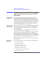
Application Response Measurement (ARM) Integration . . . . . . . . . . . . . . . . . . . . . . .
ManageX Integration . . . . . . . . . . . . . . . . . . . . . . . . . . . . . . . . . . . . . . . . . . . . . . . . . . .
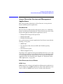
Access Points for System and Management Applications . . . . . . . . . . . . . . . . . . . . . .
Introduction. . . . . . . . . . . . . . . . . . . . . . . . . . . . . . . . . . . . . . . . . . . . . . . . . . . . . . . . .
Data Protector Access Points . . . . . . . . . . . . . . . . . . . . . . . . . . . . . . . . . . . . . . . . . . .
Examples . . . . . . . . . . . . . . . . . . . . . . . . . . . . . . . . . . . . . . . . . . . . . . . . . . . . . . . . . . .
xvi
612
613
613
616
617
618
618
619
620
627
627
637
638
640
640
642
642
644
646
648
649
649
649
653
Contents
14. ADIC/GRAU DAS and STK ACS Libraries
In This Chapter . . . . . . . . . . . . . . . . . . . . . . . . . . . . . . . . . . . . . . . . . . . . . . . . . . . . . . .
ADIC/GRAU DAS and STK ACS Integrations . . . . . . . . . . . . . . . . . . . . . . . . . . . . . . .
Configuration Basics. . . . . . . . . . . . . . . . . . . . . . . . . . . . . . . . . . . . . . . . . . . . . . . . . .
Media Management Basics . . . . . . . . . . . . . . . . . . . . . . . . . . . . . . . . . . . . . . . . . . . .
The ADIC/GRAU DAS Library Device . . . . . . . . . . . . . . . . . . . . . . . . . . . . . . . . . . . . .
Direct Access to the Library: Installation and Configuration . . . . . . . . . . . . . . . . .
Connecting Library Drives . . . . . . . . . . . . . . . . . . . . . . . . . . . . . . . . . . . . . . . . . . . . .
Preparing for Installation. . . . . . . . . . . . . . . . . . . . . . . . . . . . . . . . . . . . . . . . . . . . . .
Installing the DAS Media Agent . . . . . . . . . . . . . . . . . . . . . . . . . . . . . . . . . . . . . . . .
Using the Data Protector GUI . . . . . . . . . . . . . . . . . . . . . . . . . . . . . . . . . . . . . . . . .
Indirect Access to the DAS Library: Installation and Configuration . . . . . . . . . . .
Using Data Protector to Access the ADIC/GRAU Library . . . . . . . . . . . . . . . . . . . .
The STK ACS Library Device . . . . . . . . . . . . . . . . . . . . . . . . . . . . . . . . . . . . . . . . . . . .
Direct Access to the Library: Installation and Configuration . . . . . . . . . . . . . . . . .
Media Management Basics . . . . . . . . . . . . . . . . . . . . . . . . . . . . . . . . . . . . . . . . . . . .
Connecting Library Drives . . . . . . . . . . . . . . . . . . . . . . . . . . . . . . . . . . . . . . . . . . . . .
Installing the ACS Media Agent to Use the StorageTek Library . . . . . . . . . . . . . .
Using Data Protector to Configure the STK ACS Library . . . . . . . . . . . . . . . . . . . .
Indirect Access to the Library: Installation and Configuration . . . . . . . . . . . . . . . .
Using Data Protector to Access the STK ACS Library. . . . . . . . . . . . . . . . . . . . . . .
Troubleshooting Library Installation and Configuration . . . . . . . . . . . . . . . . . . . . . .
656
657
659
659
662
662
662
662
664
669
670
671
680
680
680
681
681
686
686
687
697
A. Further Information
In This Appendix . . . . . . . . . . . . . . . . . . . . . . . . . . . . . . . . . . . . . . . . . . . . . . . . . . . . . . .A-2
Backing Up and Restoring UNIX Specifics . . . . . . . . . . . . . . . . . . . . . . . . . . . . . . . . . .A-3
VxFS Snapshot . . . . . . . . . . . . . . . . . . . . . . . . . . . . . . . . . . . . . . . . . . . . . . . . . . . . . . .A-3
Data Protector Commands . . . . . . . . . . . . . . . . . . . . . . . . . . . . . . . . . . . . . . . . . . . . . . .A-7
Performance Considerations . . . . . . . . . . . . . . . . . . . . . . . . . . . . . . . . . . . . . . . . . . . . . .A-8
The Infrastructure . . . . . . . . . . . . . . . . . . . . . . . . . . . . . . . . . . . . . . . . . . . . . . . . . . . .A-8
Configuring Backups and Restores . . . . . . . . . . . . . . . . . . . . . . . . . . . . . . . . . . . . . .A-10
Example of Scheduled Eject of Media . . . . . . . . . . . . . . . . . . . . . . . . . . . . . . . . . . . . . .A-14
Schedule the Report Group . . . . . . . . . . . . . . . . . . . . . . . . . . . . . . . . . . . . . . . . . . . .A-14
Add the Report to the Report Group and Configure It . . . . . . . . . . . . . . . . . . . . . . .A-14
Copy the Script to the Specified Directory . . . . . . . . . . . . . . . . . . . . . . . . . . . . . . . .A-15
Examples of Pre-Exec and Post-Exec Commands for UNIX . . . . . . . . . . . . . . . . . . . .A-20
Disaster Recovery:
Move Kill Links on HP-UX 11.x . . . . . . . . . . . . . . . . . . . . . . . . . . . . . . . . . . . . . . . . . .A-25
xvii
Contents
Creating a libaci.o on AIX . . . . . . . . . . . . . . . . . . . . . . . . . . . . . . . . . . . . . . . . . . . . . . .A-26
Example of the Package Configuration File . . . . . . . . . . . . . . . . . . . . . . . . . . . . . . . . .A-28
Example of the Package Control File . . . . . . . . . . . . . . . . . . . . . . . . . . . . . . . . . . . . . .A-38
Data Protector Log Files Example Entries. . . . . . . . . . . . . . . . . . . . . . . . . . . . . . . . . .A-44
debug.log . . . . . . . . . . . . . . . . . . . . . . . . . . . . . . . . . . . . . . . . . . . . . . . . . . . . . . . . . . .A-44
sm.log. . . . . . . . . . . . . . . . . . . . . . . . . . . . . . . . . . . . . . . . . . . . . . . . . . . . . . . . . . . . . .A-46
inet.log . . . . . . . . . . . . . . . . . . . . . . . . . . . . . . . . . . . . . . . . . . . . . . . . . . . . . . . . . . . . .A-46
media.log . . . . . . . . . . . . . . . . . . . . . . . . . . . . . . . . . . . . . . . . . . . . . . . . . . . . . . . . . . .A-46
upgrade.log . . . . . . . . . . . . . . . . . . . . . . . . . . . . . . . . . . . . . . . . . . . . . . . . . . . . . . . . .A-47
Windows Manual Disaster Recovery Preparation Template . . . . . . . . . . . . . . . . . . . .A-49
Changing Block Size on Windows Media Agent. . . . . . . . . . . . . . . . . . . . . . . . . . . . . .A-51
Glossary
Index
xviii
Printing History
The manual printing date and part number indicate its current edition.
The printing date will change when a new edition is printed. Minor
changes may be made at reprint without changing the printing date. The
manual part number will change when extensive changes are made.
Manual updates may be issued between editions to correct errors or
document product changes. To ensure that you receive the updated or
new editions, you should subscribe to the appropriate product support
service. See your HP sales representative for details.
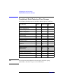
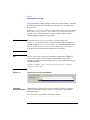
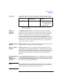
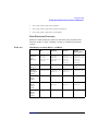
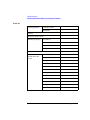
Table 1
Edition History
Part Number
Manual Edition
Product
B6960-90057
August 2002
Data Protector Release
A.05.00
B6960-90078
May 2003
Data Protector Release
A.05.10
xix
xx
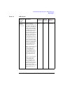
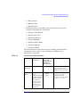
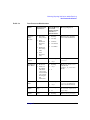
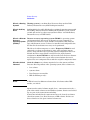
Conventions
The following typographical conventions are used in this manual.
Table 2
Convention
Italic
Meaning
Example
Book or manual
titles, and manual
page names
Refer to the HP OpenView
Storage Data Protector
Integration Guide for more
information.
Provides emphasis
You must follow these steps.
Specifies a variable
that you must supply
when entering a
command
At the prompt type:
rlogin your_name where
you supply your login name.
Bold
New terms
The Data Protector Cell
Manager is the main ...
Computer
Text and items on the
computer screen
The system replies: Press
Enter
Command names
Use the grep command ...
File and directory
names
/usr/bin/X11
Process names
Check to see if Data
Protector Inet is
running.
Window/dialog box
names
In the Backup Options
dialog box...
Text that you must
enter
At the prompt, type: ls -l
Keyboard keys
Press Return.
Keycap
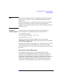
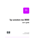
xxi
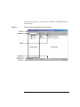
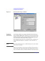
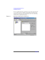
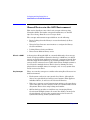
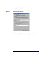
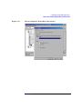
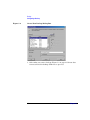
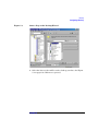
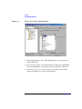
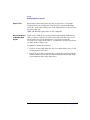
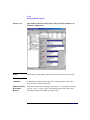
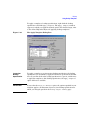
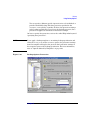
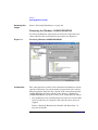
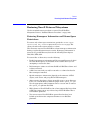
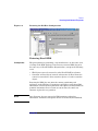
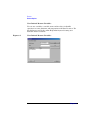
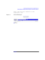
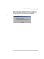
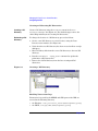
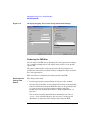
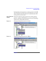
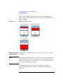
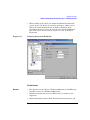
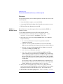
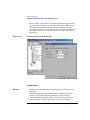
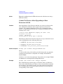
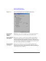
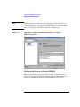
Data Protector provides a cross-platform (Windows and UNIX) graphical
user interface.
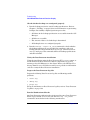
Figure 1
Data Protector Graphical User Interface
xxii
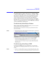
Contact Information
General
Information
General information about Data Protector can be found at
http://www.hp.com/go/dataprotector
Technical Support Technical support information can be found at the HP Electronic
Support Centers at
http://support.openview.hp.com/support.jsp
Information about the latest Data Protector patches can be found at
http://support.openview.hp.com/patches/patch_index.jsp
For information on the Data Protector required patches, refer to the HP
OpenView Storage Data Protector Software Release Notes.
HP does not support third-party hardware and software. Contact the
respective vendor for support.
Documentation
Feedback
Your comments on the documentation help us to understand and meet
your needs. You can provide feedback at
http://ovweb.external.hp.com/lpe/doc_serv/
Training
Information
For information on currently available HP OpenView training, see the
HP OpenView World Wide Web site at
http://www.openview.hp.com/training/
Follow the links to obtain information about scheduled classes, training
at customer sites, and class registration.
xxiii
xxiv
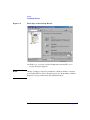
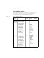
Data Protector Documentation
Data Protector documentation comes in the form of manuals and online
Help.
Manuals
Data Protector manuals are available in printed format and in PDF
format. Install the PDF files during the Data Protector setup procedure
by selecting the User Interface component on Windows or the
OB2-DOCS component on UNIX. Once installed, the manuals reside in the
<Data_Protector_home>\docs directory on Windows and in the
/opt/omni/doc/C/ directory on UNIX. You can also find the manuals in
PDF format at http://ovweb.external.hp.com/lpe/doc_serv/
HP OpenView Storage Data Protector Administrator’s Guide
This manual describes typical configuration and administration tasks
performed by a backup administrator, such as device configuration,
media management, configuring a backup, and restoring data.
HP OpenView Storage Data Protector Installation and Licensing
Guide
This manual describes how to install the Data Protector software, taking
into account the operating system and architecture of your environment.
This manual also gives details on how to upgrade Data Protector, as well
as how to obtain the proper licenses for your environment.
HP OpenView Storage Data Protector Integration Guide
This manual describes how to configure and use Data Protector to back
up and restore various databases and applications. There are two
versions of this manual:
• HP OpenView Storage Data Protector Windows Integration Guide
This manual describes integrations running the Windows operating
systems, such as Microsoft Exchange, Microsoft SQL, Oracle, SAP
R/3, Informix, Sybase, NetApp Filer, HP OpenView Network Node
Manager, and Lotus Domino R5 Server.
xxv
• HP OpenView Storage Data Protector UNIX Integration Guide
This manual describes integrations running on the UNIX operating
system, such as Oracle, SAP R/3, Informix, Sybase, NetApp Filer,
IBM DB2 UDB, HP OpenView Network Node Manager, and Lotus
Domino R5 Server.
HP OpenView Storage Data Protector Concepts Guide
This manual describes Data Protector concepts and provides background
information on how Data Protector works. It is intended to be used with
the task-oriented HP OpenView Storage Data Protector Administrator’s
Guide.
HP OpenView Storage Data Protector EMC Symmetrix
Integration Guide
This manual describes how to install, configure, and use the EMC
Symmetrix integration. It is intended for backup administrators or
operators.
It describes the integration of Data Protector with the EMC Symmetrix
Remote Data Facility and TimeFinder features for Symmetrix Integrated
Cached Disk Arrays. It covers the backup and restore of file systems and
disk images, as well as online databases, such as Oracle and SAP R/3.
HP OpenView Storage Data Protector HP StorageWorks Disk
Array XP Integration Guide
This manual describes how to install, configure, and use the integration
of Data Protector with HP StorageWorks Disk Array XP. It is intended
for backup administrators or operators. It covers the backup and restore
of Oracle, SAP R/3, Microsoft Exchange, and Microsoft SQL.
HP OpenView Storage Data Protector EVA/VA/MSA Integration
Guide
This manual describes how to install, configure, and use the integration
of Data Protector with HP StorageWorks Virtual Array, HP
StorageWorks Enterprise Virtual Array or HP StorageWorks Modular
SAN Array 1000. It is intended for backup administrators or operators.
It covers the backup and restore of Oracle, SAP R/3, Microsoft Exchange,
and Microsoft SQL.
xxvi
HP OpenView Storage Data Protector Integration Guide for HP
OpenView
This manual describes how to install, configure, and use the integration
of Data Protector with HP OpenView Service Information Portal, HP
OpenView Service Desk, and HP OpenView Reporter. It is intended for
backup administrators. It discusses how to use the OpenView
applications for Data Protector service management.
HP OpenView Storage Data Protector MPE/iX System User Guide
This manual describes how to install and configure MPE/iX clients, and
how to back up and restore MPE/iX data.
HP OpenView Storage Data Protector Integration Guide for HP
OpenView Operations
This manual describes how to monitor and manage the health and
performance of the Data Protector environment with HP OpenView
Operations (OVO), HP OpenView Service Navigator, and HP OpenView
Performance (OVP).
HP OpenView Storage Data Protector Software Release Notes
This manual gives a description of new features of HP OpenView Storage
Data Protector A.05.10. It also provides information on supported
configurations (devices, platforms and online database integrations,
SAN, and ZDB), required patches, and limitations, as well as known
problems and workarounds. An updated version of the supported
configurations is available at
http://www.openview.hp.com/products/datapro/spec_0001.html.
Online Help
Data Protector provides context-sensitive (F1) help and Help Topics for
Windows and UNIX platforms.
xxvii
xxviii
In This Book
The HP OpenView Storage Data Protector Administrator’s Guide
describes how to configure and use the Data Protector network backup
product. You must properly install Data Protector before you can
configure it.
NOTE
This manual describes Data Protector functionality without specific
information on particular licensing requirements. Some Data Protector
functionality is subject to specific licenses. The related information is
covered in the HP OpenView Storage Data Protector Installation and
Licensing Guide.
Audience
This manual is intended for network administrators responsible for
maintaining and backing up systems on the network.
Conceptual information can be found in the HP OpenView Storage Data
Protector Concepts Guide, which is recommended in order to fully
understand the fundamentals and the model of Data Protector.
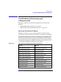
xxix
Organization
The manual is organized as follows:
Chapter 1
“Introducing Data Protector” on page 1.
Chapter 2
“Configuring and Using Backup Devices” on page 17.
Chapter 3
“Configuring Users and User Groups” on page 81.
Chapter 4
“Managing Media” on page 97.
Chapter 5
“Backup” on page 151.
Chapter 6
“Restore” on page 267.
Chapter 7
“Monitoring, Reporting, Notifications, and the Event
Log” on page 307.
Chapter 8
“Manager-of-Managers Environment” on page 359.
Chapter 9
“Managing the Data Protector Internal Database” on
page 381.
Chapter 10
“Disaster Recovery” on page 435.
Chapter 11
“Customizing the Data Protector Environment” on
page 521.
Chapter 12
“Troubleshooting” on page 547.
Chapter 13
“Integrations with Other Applications” on page 611.
Chapter 14
“ADIC/GRAU DAS and STK ACS Libraries” on page
655.
Appendix A
“Further Information” on page A-1.
Glossary
Definition of terms used in this manual.
xxx
1
Introducing Data Protector
Chapter 1
1
Introducing Data Protector
In This Chapter
In This Chapter
This chapter contains some general principles on how Data Protector
works, covered in these sections:
“The Data Protector Cell Environment” on page 3
“Using the Data Protector User Interface” on page 6
“Overview of Tasks to Set Up Data Protector” on page 15
2
Chapter 1
Introducing Data Protector
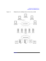
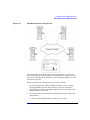
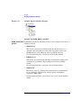
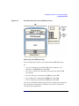
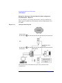
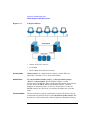
The Data Protector Cell Environment
The Data Protector Cell Environment
The Data Protector cell is a network environment containing a Cell
Manager, clients, and backup devices. The Cell Manager has the
main Data Protector control software installed and is the central point
from which the cell is administered and backup and restore operations
are controlled. Systems that are to be backed up can be added to the cell
and set up as Data Protector clients. When Data Protector performs a
backup of data from these clients, it saves the data to media (such as
magnetic tapes, or hard disks) contained within backup devices.
The Data Protector Internal Database (IDB) keeps track of the files
backed up, making it is easy to browse and restore them, either singly or
collectively.
The Cell Manager is the main control center for the cell and contains
the IDB. It runs the core Data Protector software and the Session
Manager, which starts and stops backup and restore sessions and writes
session information to the IDB.
Any system within a chosen cell environment can be set up as a Data
Protector client. Essentially, a client is a system that can be backed up,
a system connected to a backup device with which the backup data can
be saved, or both. The role of the client depends on whether it has a Disk
Agent or a Media Agent installed.
A client that will be backed up using Data Protector must have a Disk
Agent installed. Data Protector controls the access to the disk. The Disk
Agent lets you back up information from, or restore information to, the
client system.
A client system with connected backup devices must have a Media
Agent installed. This software controls the access to the backup device.
The Media Agent controls reading from and writing to a backup device’s
media.
A backup device performs the actual recording of backup data to a
recording medium, and the retrieval of restore data from a medium.
The physical object upon which the data is recorded, such as a DAT tape
or a hard disk, is called the backup medium.
Chapter 1
3
Introducing Data Protector
The Data Protector Cell Environment
NOTE
For further information on these terms, or on the principles of Data
Protector operation, see the HP OpenView Storage Data Protector
Concepts Guide.
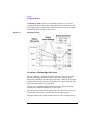
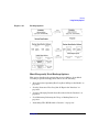
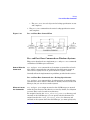
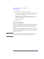
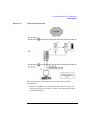
How a Backup Session Works
A backup session starts either when a backup is requested through the
user interface, or when a scheduled backup is initiated. During this
session, Data Protector backs up the requested filesystems and disks to
the specified media.
1. The Cell Manager determines the type of session that has been
requested (backup) and starts the appropriate Session Manager.
2. The Session Manager reads the backup specification and determines
what needs to be backed up and which devices to use.
3. The Session Manager then starts a Media Agent for each media drive
that will be used and a Disk Agent for each disk that will be read.
4. The Monitor window appears. This window lets you respond to mount
requests and view the progress of a backup session.
5. The Disk Agents start sending data to the Media Agent.
6. If more than one Disk Agent is used, the Disk Agents send data to the
Media Agent concurrently and the Media Agent places the data on
the medium.
7. As each block of data is written to the medium, the Media Agent
sends information to the Session Manager about what has been
backed up. The Session Manager uses this information to update the
catalog of backed-up files in the IDB.
How a Restore Session Works
A restore session starts when a restore is requested. During this session,
Data Protector performs a restore of requested files and disks from the
media.
1. You specify which filesystems to restore and how to restore them,
using the Data Protector user interface.
4
Chapter 1
Introducing Data Protector
The Data Protector Cell Environment
2. The Cell Manager determines the type of session that has been
requested (restore), and starts the appropriate Session Manager.
3. The Session Manager then determines which filesystems or
directories to restore, which devices to use, and what restore options
have been specified.
4. The Session Manager starts the appropriate Disk Agent and Media
Agent. For example, a Media Agent is started for the media (tape)
drive that will be used and a Disk Agent is started for the disk to
which the data will be restored.
5. The Monitor window appears. This window lets you respond to
mount requests and view the progress of a restore session.
6. The Media Agent starts sending data to the Disk Agent.
7. The Session Manager then updates the IDB and the Disk Agent
writes the data to the disk.
Chapter 1
5
Introducing Data Protector
Using the Data Protector User Interface
Using the Data Protector User Interface
There is one Data Protector user interface, available on Windows and
UNIX platforms. It consists of the Data Protector graphical user
interface (GUI) and the command-line interface.
Using the Data Protector user interface, you can perform all Data
Protector tasks.
Figure 1-1
HP OpenView Storage Data Protector Graphical User Interface
6
Chapter 1
Introducing Data Protector
Using the Data Protector User Interface
Graphical User Interface
The Data Protector graphical user interface (GUI) uses features such as
buttons and text boxes to enhance usability. Whenever possible,
drop-down lists are provided to allow you to select from a list instead of
typing in your selection. In addition, a comprehensive online Help
system provides information about each window and each task.
Depending on the user rights, you can either use the GUI to access the
complete Data Protector functionality or to access only specific contexts.
For more information on user rights, refer to “Data Protector User
Rights” on page 83.
For more information on Data Protector contexts, refer to “Context List”
on page 9.
Starting GUI on
Windows
Platforms
To start the Data Protector GUI on Windows platforms, do one of the
following:
• Click Start on the Windows desktop and click Data Protector
Manager from the HP OpenView Storage Data Protector program
group to start the GUI for the complete Data Protector functionality.
• Use the manager command to start the GUI for the complete Data
Protector functionality.
Context-specific options for this command enable you to start one or
more Data Protector contexts. For example, the command
manager -backup -restore
starts the Data Protector Backup and Restore contexts.
To specify the Cell Manager you want to connect to, use the following
command: manager -server <Cell Manager_name>.
For more information on these commands, refer to the omnigui man
page.
Starting GUI on
UNIX Platforms
To use the Data Protector GUI on UNIX platforms, enter:
xomni
to start the GUI with the complete Data Protector
functionality
xomniadmin
to start the administration (configuration) of clients,
users, reports, and the IDB GUI
xomnibackup
to start the backup GUI
Chapter 1
7
Introducing Data Protector
Using the Data Protector User Interface
xomnicellmon to start the MoM cell monitoring GUI
xomnimm
to start the media and devices management GUI
xomnimonitor to start the monitoring a single cell GUI
xomnirestore to start the restore GUI
xomniinstrec To start the instant recovery GUI. A special license is
needed to start this GUI. Refer to the HP OpenView
Storage Data Protector HP StorageWorks Disk Array
XP Integration Guide for more information on the
instant recovery functionality and to the HP OpenView
Storage Data Protector Installation and Licensing
Guide for more information on Data Protector licenses.
xomnimom
to start the Manager-of-Managers GUI
For more information on these commands, refer to the omnigui man
page.
Printing from the Data Protector Graphical User Interface
Data Protector lets you print from the GUI. You can print session
messages, reports, event logs, and various lists (for example, lists of
configured clients and devices). Generally, you can print anything
displayed as a list in the Results Area, and the online Help topics.
However, you are not able to print any of the Properties. Instead, you
can use the Data Protector reporting functionality to configure various
reports about your backup environment. For more information on
reporting, refer to “Data Protector Reporting” on page 315.
Prerequisite
You must have a printer already configured on your system.
When you click Print on HP-UX, you can choose among predefined
printers. Note that if you do not have a proper printer driver installed,
you are not able to print. In that case, choose a PS printer and select the
Print to file option. You can then send the generated file to the PS
printer using the UNIX lp command from the UNIX terminal.
On Windows, however, a displayed printer in the Select Printer
window means that the printer is already configured on your system and
you are able to print.
For detailed steps on printing, refer to online Help, index keyword
“printing from GUI”.
8
Chapter 1
Introducing Data Protector
Using the Data Protector User Interface
Elements of the Data Protector Graphical User Interface
For the visual representation of the GUI elements, refer to Figure 1-1 on
page 6.
Context List
The Context List is a drop-down list, from which you can select the
management contexts described below:
Clients
Controls all of the client systems in
the current Data Protector cell. You
can add, delete, and monitor any
client within the cell.
Users
Adds and removes users, user groups
and their rights.
Devices & Media
Controls device and media
maintenance and access to media
which store the data.
Backup
Controls which data is to be backed
up, where, and how.
Restore
Controls which data is to be restored,
where, and how.
Instant Recovery
Controls the split mirror instant
recovery processes. A special license
is needed to display this context.
Refer to the HP OpenView Storage
Data Protector HP StorageWorks Disk
Array XP Integration Guide for more
information on the instant recovery
functionality and to the HP
OpenView Storage Data Protector
Installation and Licensing Guide for
more information on Data Protector
licenses.
Reporting
Allows you to get information on your
cell configuration, backup
specifications, media and media
pools, as well as on specific sessions
and objects.
Chapter 1
9
Introducing Data Protector
Using the Data Protector User Interface
Internal Database
Allows you to get information on the
IDB storage capacity, database
objects, and sessions.
Monitor
Allows you to monitor sessions that
are in progress.
Scoping Pane
The Scoping Pane provides a tree of items that can be selected to open
a view. Selecting an item in the Scoping Pane displays information in the
Results Area.
Results Area
Selecting an item in the Scoping Pane displays corresponding
information in the Results Area. If you click Clients in the Scoping
Pane, the Results Area displays a list of all the clients within your cell.
Navigation Tabs
Navigation Tabs appear at the bottom of the Scoping Pane. These tabs
allow you to switch between the two possible item list views in the
Scoping Pane: Objects and Tasks. Not every Scoping Pane has these
views.
Results Tab
Tab Name
What the Tab Displays in the Scoping Pane
Objects
A hierarchical presentation of data, similar to the
directory tree in Windows Explorer. For example, in
the Devices & Media context, the Scoping Pane will
display the list of devices and media configured with
Data Protector.
Tasks
A list of tasks that you can perform. Clicking a task
displays a wizard that will walk you through an entire
task, such as backing up a file.
The name on the Results Tab corresponds to the name of the item
currently selected in the Scoping Pane. You can click the Pin icon on the
toolbar to make this view "stick" and keep it available for the future. For
example, if you need to use the GUI to look up some other information,
but you want to continue with the previous view later, you can access
this view by selecting the "pinned" tab.
You can remove one or more tabs by right-clicking the area and selecting
Remove Tab or Remove Other Tabs.
10
Chapter 1
Introducing Data Protector
Using the Data Protector User Interface
The Command-Line Interface
The command-line interface (CLI) follows the standard UNIX format for
commands and options and provides complete Data Protector
functionality. You can use these commands in scripts to speed up your
commonly performed tasks.
The omniintro man page lists all supported Data Protector commands,
as well as differences between commands on the UNIX and Windows
platforms.
See also “Data Protector Commands” on page A-7.
Chapter 1
11
Introducing Data Protector
Using the Data Protector User Interface
Data Protector Online Resources
Information about Data Protector is available in this manual and in the
online Help system. This manual contains the information you need to
plan and administer your Data Protector network, and information on
some more commonly performed tasks. The online Help system contains
the information you need to perform all available tasks.
The following Data Protector online resources are available:
Help Topics
Online Help with task instructions
and reference information. You can
select topics by using the contents
list, index, or search facility.
Help Navigator
Context-sensitive Help that provides
detailed help on the current task.
Online Documentation
Online manuals in PDF format that
can be read with the Adobe Acrobat
Reader.
Data Protector on the Web
Opens your Web browser to the Data
Protector homepage, where more
information about Data Protector can
be found.
Online Support
Opens your Web browser to the HP
OpenView interactive Online Support
service page.
About
Displays version and copyright
information for Data Protector, as
well as licensing information.
You can access the online resources by either using the Help drop-down
menu or the Help buttons provided on the Data Protector windows.
Hyperlinks (cross-references) to additional information and definitions
help you navigate through online Help. You click the hyperlinked word
or phrase to jump to the new topic. Hyperlinked words and phrases are
marked with either solid underlining or different color.
Starting and Using the Help Navigator
The Help Navigator provides context-sensitive online Help, which can be
used to find information about the current GUI panel or task.
12
Chapter 1
Introducing Data Protector
Using the Data Protector User Interface
If the GUI concerned is running on Windows, the Help Navigator is
dynamic: Once it is started, its contents automatically change as you go
to the next page of the wizard or to another view in the Data Protector
user interface.
To start the Help Navigator, either:
• Press F1
• Click Help Navigator from the Help menu, or
• Click the Help Navigator icon (the question mark) on the button bar
Using the Online Manuals
Data Protector provides online manuals in PDF format that can be read
using the Adobe Acrobat Reader. Once installed, the online manuals
reside in the <Data_Protector_home>\docs directory (Windows) or
the /opt/omni/doc/C directory (HP-UX or Solaris) on the Cell Manager
system.
Using Microsoft Management Console (MMC)
On Windows systems, it is possible to integrate the Data Protector GUI
with the Microsoft Management Console.
The Microsoft Management Console (MMC) is a Graphical User
Interface (GUI) that lets you manage and run your administrative tools
within a common interface environment. You can add already installed
software, hardware, or network management applications to the console,
where the primary type of tool that can be added to the console is called a
snap-in.
The Data Protector snap-in, known as OB2_Snap, provides a basic
integration of Data Protector and the MMC. Using OB2_Snap, you can
go to the Data Protector home page or to Data Protector Web/Java
Reporting. You can also start the Data Protector GUI on Windows from
the MMC.
Proceed as follows to add OB2_Snap to the MMC.
1. Download the MMC software from
http://www.microsoft.com/downloads/.
2. From the Windows desktop, click Start, and then select Run.
Chapter 1
13
Introducing Data Protector
Using the Data Protector User Interface
3. In the Open text box, enter mmc to open the Microsoft Management
Console window.
4. From the Console menu, select Add/Remove Snap-in. In the
Standalone property page of the Add/Remove Snap-in window, click
Add.
5. In the Add Standalone Snap-in window, select HP OpenView
Storage Data Protector. Click Close to exit the window, then click
OK to get back to the Microsoft Management Console window.
The HP OpenView Storage Data Protector item will be displayed
under Console Root. Once you have added the applications to MMC,
save the file as <Console_Name>.msc.
14
Chapter 1
Introducing Data Protector
Overview of Tasks to Set Up Data Protector
Overview of Tasks to Set Up Data Protector
Although configuring Data Protector is easy, some advanced planning
will help you configure the environment and optimize your backups. This
section provides an overview of the global tasks to set up a backup
environment.
Depending on the size and complexity of your environment, you may not
need to go through all these steps.
1. Analyze your network and organizational structure. Decide which
systems need to be backed up.
For more information refer to the HP OpenView Storage Data
Protector Concepts Guide.
2. Check whether there are any special applications and databases
which you want to back up, such as Microsoft Exchange, Microsoft
SQL, Oracle, SAP R/3, or others. Data Protector provides specific
integrations with these products.
Refer to the HP OpenView Storage Data Protector Integration Guide
for instructions on how to configure the integrations.
3. Decide on the configuration of your Data Protector cell, such as the
following:
• System to be your Cell Manager
• Systems on which you want to install the user interface
• Type of backup - local backup versus network backup
• Systems to control backup devices
4. Purchase the required Data Protector licenses for your setup. This
way you obtain the passwords you need to have installed.
Alternatively, you can operate Data Protector using an instant-on
password. However, this is valid only for 60 days from the date of
installation. Refer to the HP OpenView Storage Data Protector
Installation and Licensing Guide for details.
5. Decide how you want to structure your backups:
• Which media pools would you like to have, and how will they be
used?
Chapter 1
15
Introducing Data Protector
Overview of Tasks to Set Up Data Protector
• Which devices will be used, and how?
• Which user groups do you want to have, and what will they do?
• How many backup specifications do you want to have, and how
should they be grouped?
6. Install the Data Protector Cell Manager and Installation Server(s).
Then use the Data Protector GUI to distribute Data Protector agents
to other systems. Also, connect the devices (tape drives) to the
systems that will control them. See the HP OpenView Storage Data
Protector Installation and Licensing Guide for detailed instructions.
7. Configure the device(s). See Chapter 2, “Configuring and Using
Backup Devices,” on page 17.
8. Configure the pools and optionally prepare the media. See Chapter 4,
“Managing Media,” on page 97.
9. Set up the backup specifications, including scheduling. See Chapter 5,
“Backup,” on page 151.
10. Configure the IDB. See Chapter 9, “Managing the Data Protector
Internal Database,” on page 381.
11. Configure reports, if required. See Chapter 7, “Monitoring, Reporting,
Notifications, and the Event Log,” on page 307.
12. Consider preparing for disaster recovery if your disk fails. See
Chapter 10, “Disaster Recovery,” on page 435.
13. Become familiar with tasks such as:
• How to work with failed backups
• Performing restores
• Testing disaster recovery
• IDB maintenance
16
Chapter 1
2
Configuring and Using Backup
Devices
Chapter 2
17
Configuring and Using Backup Devices
In This Chapter
In This Chapter
This chapter includes information on the following topics:
“Configuring Backup Devices” on page 20
“Configuring Standalone Devices” on page 23
“Configuring File Devices” on page 26
“Configuring Library Devices” on page 29
“Configuring Libraries with Multiple Systems” on page 32
“Configuring Magazine Devices” on page 34
“Configuring Stacker Devices” on page 35
“Configuring a Library for Mixed Media” on page 37
“Configuring Devices for Direct Backup” on page 38
“Support of New Devices” on page 41
“Using Several Drive Types in a Library” on page 42
“Configuring Magazine Devices” on page 34
“Shared Devices in the SAN Environment” on page 44
“Drive Cleaning” on page 61
“Busy Drive Handling” on page 65
“Activating Barcode Support” on page 66
“Activating Cartridge Memory Support” on page 68
“Disabling a Backup Device” on page 70
“Removing a Backup Device” on page 72
“Device Locking” on page 74
“Device Concurrency, Segment Size, and Block Size” on page 76
18
Chapter 2
Configuring and Using Backup Devices
In This Chapter
NOTE
Backup devices (like tape drives) are subject to specific Data Protector
licenses. See the HP OpenView Storage Data Protector Installation and
Licensing Guide for details.
Chapter 2
19
Configuring and Using Backup Devices
Configuring Backup Devices
Configuring Backup Devices
Preparation of a backup device consists of connecting the device to the
system and knowing which of the (working) associated device files (SCSI
address) is to be used. To configure a device:
1. Connect the device to a computer. Refer to the documentation that
comes with the device.
2. Make sure that you have done the following:
UNIX
Systems
Create or find the device filename for a device
connected to a UNIX system. For detailed steps, refer
to the online Help index keyword “creating device
filenames” or “finding device filenames”. For further
information, refer to Appendix B of the HP OpenView
Storage Data Protector Installation and Licensing
Guide.
Windows
Systems
Provide a SCSI II address and load the driver that
will be used with a device connected to a Windows
system.
For tape drives, the Windows native tape driver can
be:
• unloaded (preferred) or
• loaded
The device filename depends on whether a
Windows native tape driver is used with a
particular tape drive.
On how to obtain the SCSI II address, refer to the
online Help index keyword “creating SCSI addresses”.
For further information, refer to Appendix B of the
HP OpenView Storage Data Protector Installation and
Licensing Guide.
20
Chapter 2
Configuring and Using Backup Devices
Configuring Backup Devices
Windows
Robotics
Drivers
On Windows, disable the Removable Storage Service
or Windows medium changer (robotics) driver before
you configure the robotics device with Data Protector.
For detailed steps, refer to the online Help index
keyword “robotics drivers”. For further information,
refer to Appendix B of the HP OpenView Storage Data
Protector Installation and Licensing Guide.
Cartridge
Memory
If your backup device is connected to a Windows
system and uses media with Cartridge Memory, make
sure that your SCSI II card supports execution of
16-byte CDB SCSI II commands. On the UNIX and
Novell platforms, you need a tape driver which
supports the respective SCSI II commands.
3. Boot the system to have the device recognized by the system.
4. Configure the device, as described in the following sections, so that
you can use it with Data Protector.
5. Prepare the media that you want to use with your backups. On how to
format media, refer to “Formatting Media” on page 108.
A default media pool is used with each device so that you do not have
to create one. If you want to create your own media pool, refer to
“Creating a Media Pool” on page 102.
Figure 2-1 shows the relationship between the backup specification,
devices, and media pools. The devices are referred to in the backup
specification, while each device is linked to a default media pool. This
media pool can be changed in the backup specification.
Chapter 2
21
Configuring and Using Backup Devices
Configuring Backup Devices
Figure 2-1
How Backup Specifications, Devices, and Media Pools Relate
22
Chapter 2
Configuring and Using Backup Devices
Configuring Standalone Devices
Configuring Standalone Devices
What Are
Standalone
Devices?
Standalone devices are simple backup devices with one drive that reads
from or writes to one medium at a time. They are used for small-scale
backups. When a medium is full, the operator has to manually replace it
with a new medium so that the backup can proceed. Standalone devices
are not appropriate for large, unattended backups.
Data Protector provides simple configuration and management of media
used in standalone backup devices.
How to Configure
a Standalone
Device
Once you have prepared the device for configuration as described in
“Configuring Backup Devices” on page 20, configure a standalone device
so that you can use it with Data Protector. In the Devices & Media
context, right-click Devices and click Add Device. In the Add Device
wizard, specify the Standalone device type. Refer to Figure 2-2.
For detailed steps and examples, refer to the online Help index keyword
“configuring standalone devices”.
Data Protector supports a specific set of backup devices. Refer to the HP
OpenView Storage Data Protector Software Release Notes for a detailed
list of supported devices and their corresponding media types.
In case you want to use a device that is not in the list of supported
devices, refer to “Support of New Devices” on page 41.
TIP
You can also let Data Protector automatically configure most common
devices. You still need to prepare the media for a backup session, but
Data Protector determines the name, policy, media type, media policy,
and the device’s SCSI II address or device file. For detailed steps, refer to
the online Help index keyword “autoconfiguring backup devices”.
Chapter 2
23
Configuring and Using Backup Devices
Configuring Standalone Devices
Figure 2-2
Specifying Device Type and Name
Configuring
Device Chains
Data Protector allows you to configure standalone devices of the same
type into device chains. When a medium in one device becomes full, the
backup automatically continues on the medium in the next device in the
device chain. Device chains are possible for only one Media Agent, that
is, you can connect a device chain to only one system.
The configuration is the same as for a standalone device, except that you
enter multiple SCSI addresses (on Windows) or device filenames (on
UNIX).
NOTE
The order in which the devices are added determines the order in which
Data Protector uses them.
When all of the media in a device chain are full, Data Protector issues a
mount request. The operator must replace the medium in the first device
with a new medium, format it, and then confirm the mount request. Data
24
Chapter 2
Configuring and Using Backup Devices
Configuring Standalone Devices
Protector can immediately use media that are recognized and
unprotected. Data Protector can also use blank media, so that you do not
have to format them.
Chapter 2
25
Configuring and Using Backup Devices
Configuring File Devices
Configuring File Devices
What Are File
Devices?
A file device is a file in a specified directory to which you back up data
instead of writing it to a tape. File devices are available for standalone
devices and Jukebox devices simulation. The file device functionality is
available on the Windows, HP-UX, Solaris, AIX, and Linux operating
systems.
The default capacity of a file device is 100 MB for data and 10 MB for the
catalog. The default segment size (for a 100 MB file device) is 30 MB.
The recommended segment sizes for specific file device sizes is:
Table 2-1
The Recommended Segment Sizes for Specific Device File Sizes
File size (GB)
Segment size (MB)
< 10
100
< 100
500
< 200
1000
< 300
1500
< 400
2000
< 500
2500
Data Protector never measures the amount of free space on the
filesystem; it takes either the default or the specified capacity as the file
size limit. If the disk on which the file device resides runs out of space,
the backup will fail. The largest capacity specified for a file is 500 GB on
Windows and 4 GB on UNIX systems.
Data Protector does not support using compressed files for file devices.
You can change the default file size by changing the
FileMediumCapacity parameter in the
<Data_Protector_home>\Config\Options\global file on the
Windows Cell Manager or in the /etc/opt/omni/options/global file
on the HP-UX or Solaris Cell Manager.
26
Chapter 2
Configuring and Using Backup Devices
Configuring File Devices
You specify the capacity of a file device when you first format the
medium. When you reformat the medium, you can specify a new size;
however, the originally specified size will be used. You can change the
capacity of a file device only by deleting the file from the system.
The path to a file device can be anywhere, whether it is an internal drive
or an external portable hard drive.
Handling Mount
Requests
Media are handled differently from physical devices. When a standalone
file device (medium) becomes full, Data Protector tries to write to the
same file again. Data Protector does not recognize that any other file
exists, so it issues a mount request.
When the mount request occurs, the existing file has to be moved or
renamed (for example, by exchanging the ZIP media). The original file
should no longer exist after the move. You then need to confirm the
mount request. Data Protector will recreate the original file with the
default file capacity. After the backup is finished, the file created by Data
Protector contains the last part of the backup.
For Jukebox file devices, Data Protector issues a mount request when all
media (files) are full.
Prerequisite
Before you configure a file device on a Windows system, disable the file
compression option. This can be done using Windows Explorer.
Right-click the file, select Properties and deselect Compress under
Attributes. If Compress is selected, Data Protector will not be able to
write to the file device.
IMPORTANT
Do not use the name of an existing file for configuring a file device,
because the existing file will be overwritten.
Do not use the same filename for configuring several file devices, because
every time a file device accesses the file, it will be overwritten.
How to Configure
File Devices
To create a standalone file device, specify the Standalone device type in
the Add Device wizard. Refer to Figure 2-2. As a device address, specify
a pathname for the file device, for example, C:\My_Backup. Refer to
Figure 2-3. For detailed steps, refer to the online Help index keyword
“configuring file devices”.
Chapter 2
27
Configuring and Using Backup Devices
Configuring File Devices
To create a jukebox file device, specify the Jukebox device type in the Add
Device wizard. As device addresses, specify different pathnames that
will simulate jukebox slots. For detailed steps, refer to the online Help
index keyword “configuring file devices”.
Figure 2-3
Specifying a Pathname for a File Device
28
Chapter 2
Configuring and Using Backup Devices
Configuring Library Devices
Configuring Library Devices
What Are Library
Devices?
SCSI-II library devices, also called autoloaders, are large backup devices.
They contain a number of media cartridges in a device’s repository and
can have multiple drives handling multiple media at the same time.
Most library devices also allow you to configure automatic drive cleaning,
which is performed by Data Protector when the drive gets dirty. Refer to
“Drive Cleaning” on page 61.
A library device has a SCSI ID for each drive in the device, and one for
the library robotic mechanism. This mechanism moves media from slots
to drives and back again. For example, a library with four drives has five
SCSI IDs, four for the drives and one for the robotic mechanism.
Slot Number
Each slot in the device’s repository holds one medium. Data Protector
assigns a number to each slot, starting from 1. When managing a library,
you refer to the slots using their numbers. For example, a library with 48
repository slots has slot numbers 1, 2, 3, 4, 5, 6...47, 48.
Drive Index
The drive index identifies the mechanical position of the drive in the
library. Refer to Figure 2-4.
The index number is relevant for the robotics control. The robot knows
only index numbers and has no information about the SCSI address of
the drive. The drive index is a sequential integer (starting from 1) which
has to be coupled with the SCSI address of this drive. For example, for a
four-drive library, the drive indexes are 1,2,3,4.
If you have only one drive in the library, the drive index is 1.
Drive SCSI
Address
The drive index must match the corresponding SCSI address. This
means that you need to configure the pairs as follows:
SCSI address_A for index 1,
SCSI address_B for index 2, and so on.
Chapter 2
29
Configuring and Using Backup Devices
Configuring Library Devices
NOTE
It is not necessary to configure all drives for use with Data Protector. You
can configure one media pool for all drives, or have an independent
media pool for each drive. It is recommended that you use the default
media pool when configuring a device.
Figure 2-4
Drive Index to SCSI Address Mapping
How to Configure
a Library Device
Once you have prepared the device for configuration as described in
“Configuring Backup Devices” on page 20, configure a library device,
including its drive(s). The Add Device wizard guides you through both
configurations. For detailed steps and examples, refer to the online Help
index keyword “configuring SCSI libraries”.
TIP
You can also have Data Protector automatically configure the library
devices for you. You still need to prepare the media for a backup session,
but Data Protector determines the name, policy, media type, media
30
Chapter 2
Configuring and Using Backup Devices
Configuring Library Devices
policy, and the device file or SCSI address of the device, and also
configures the drive and slots. For detailed steps, refer to the online Help
index keyword “autoconfiguring backup devices”.
To verify the device configuration, right-click the created drive, and
choose Scan Medium. If the device is configured correctly, Data Protector
will be able to load, read, and unload media in the slots.
What’s Next?
If you have configured all the backup devices you want to use with Data
Protector, do the following:
• Add media to the media pools that you will use with the newly
configured device. Refer to “Adding Media to a Media Pool” on
page 107.
• If you want to configure a cleaning tape, refer to “Drive Cleaning” on
page 61.
• If your device uses barcodes, refer to “Activating Barcode Support” on
page 66.
• Configure a backup for your data. Refer to Chapter 5, “Backup,” on
page 151.
Chapter 2
31
Configuring and Using Backup Devices
Configuring Libraries with Multiple Systems
Configuring Libraries with Multiple Systems
You can configure a library so that each drive receives data from a
different system running a Data Protector Media Agent. The library
robotics control is still performed by one system. This improves
performance in high-end environments by allowing local backup, instead
of having to move the data over the network.
Prerequisites
• Each client system that you want to use with the drives in the library
must have the Data Protector Media Agent component installed.
• You need to have connected the backup device to the system, and a
working device file (SCSI address) must exist before you can
configure the device for use with Data Protector.
For more information on multi-drive support, see the HP OpenView
Storage Data Protector Concepts Guide.
How to Configure
Libraries with
Multiple Systems
Configure a library as described in “Configuring Library Devices” on
page 29. When you are prompted to configure drives in the library,
specify the client system that you want to use with each drive. For
detailed steps, refer to the online Help index keyword “configuring
libraries for multiple systems”.
TIP
To verify the device configuration, select a range of slots from the library
and then click Scan from the Actions menu. If the device is configured
correctly, Data Protector will be able to load, read, and unload media
back into the slots.
What’s Next?
If you have configured all the backup devices you want to use with Data
Protector, do the following:
• Add media to the media pools that you will use with the newly
configured device. See “Adding Media to a Media Pool” on page 107.
• If you want to configure a cleaning tape, see “Drive Cleaning” on
page 61.
• If your device uses barcodes, see “Activating Barcode Support” on
page 66.
32
Chapter 2
Configuring and Using Backup Devices
Configuring Libraries with Multiple Systems
• Configure a backup. See Chapter 5, “Backup,” on page 151.
Chapter 2
33
Configuring and Using Backup Devices
Configuring Magazine Devices
Configuring Magazine Devices
What Are
Magazine
Devices?
Magazine devices group a number of media into a single unit called a
magazine. A magazine allows you to handle large amounts of data more
easily than when using many individual media.
Data Protector allows you to perform media management tasks on
magazines as sets, or on a single medium.
Prerequisite
Create at least one media pool with the Magazine Support option set.
See “Adding Media to a Media Pool” on page 107.
How to Configure Magazines must be configured as libraries. Select the SCSI-II Library
a Magazine Device device type in the Add Device wizard. The media pool to which
magazines belong needs to have the Magazine Support option selected.
For detailed steps, refer to the online Help index keyword “configuring
SCSI libraries”.
TIP
You can also let Data Protector automatically configure your device for
you. You still need to prepare the media for a backup session, but Data
Protector determines the name, policy, media type, media policy, and the
device file or SCSI address of the device, and also configures the drive
and slots. For detailed steps, refer to the online Help index keyword
“autoconfiguring backup devices”.
To verify the device configuration, right-click the created drive, and then
choose Scan. If the device is configured correctly, Data Protector will be
able to load, read, and unload media in the slots.
What’s Next?
If you have configured all the backup devices you want to use with Data
Protector, do the following:
• If you want to configure a cleaning tape, refer to “Drive Cleaning” on
page 61.
• If your device uses barcodes, refer to “Activating Barcode Support” on
page 66.
• Configure a backup for your data. Refer to Chapter 5, “Backup,” on
page 151.
34
Chapter 2
Configuring and Using Backup Devices
Configuring Stacker Devices
Configuring Stacker Devices
What Are Stacker
Devices?
A stacker is a single device with one drive and sequentially accessed
media. Using stacker devices requires more human media management
than using a small library. Data Protector provides simple configuration
and management of media used in stacker backup devices.
How to Configure
a Stacker Device?
To create a stacker device, specify the Stacker device type in the Add
Device wizard. For detailed steps, refer to the online Help index keyword
“configuring stacker devices”.
Stacker Device
Media
Management
The operations scan, verify, or format have to be run separately on each
medium in a stacker device. When performing these operations, use the
Eject medium after operation option, in order to have each medium
loaded automatically (only the first medium should be loaded manually).
When all the tapes in the stacker magazine are used, the magazine must
be unmounted manually and the next one inserted.
Stackers load media in sequential order, therefore a Loose media
allocation policy is recommended. A Strict policy would require media
to be loaded in the same order as they are to be used.
Example
1. Manually load the first medium.
2. Run format/verify/scan (with Eject after operation enabled) -(next tape will be loaded automatically).
3. Repeat step 2 until all tapes are finished.
4. When all the tapes in the stacker magazine are used, unmount the
magazine manually and insert the next one.
NOTE
If a medium is not properly loaded, Data Protector will abort the medium
session.
Chapter 2
35
Configuring and Using Backup Devices
Configuring Stacker Devices
Backup and
Restore with
Stacker Devices
Only the first medium has to be manually loaded. When a tape is full, it
is ejected and the next tape is loaded automatically. When all the tapes
are used in a stacker magazine, the magazine has to be unmounted
manually and the next one has to be inserted. Again the first tape has to
be loaded manually into the drive.
NOTE
A backup or restore session will not be aborted if media are not present,
but a mount request will be issued instead. The whole session will not be
aborted if a user does not change stacker magazines within a time out
period.
36
Chapter 2
Configuring and Using Backup Devices
Configuring a Library for Mixed Media
Configuring a Library for Mixed Media
A mixed media library contains media of several types, such as DLT and
magneto-optical. It uses identical robotics to move all the media
(regardless of media type) between slots and drives.
In order to use this library functionality, configure several (sub)libraries:
one library definition per media type.
To take full advantage of this feature, perform the following steps:
• Configure at least one media pool (or use the default pool) per media
type.
• Configure the library robotics once per media type, including the slot
range for that media type. Make sure the robotics control (SCSI path
on Windows systems or device file on UNIX systems) for each of the
library robotic definitions resides on the same host and that they are
identical.
• Configure all the drives for a media type and link them to the related
library robotic and media pool. Make sure the drive index is unique
for each physical device, regardless of media type.
Chapter 2
37
Configuring and Using Backup Devices
Configuring Devices for Direct Backup
Configuring Devices for Direct Backup
This section provides the configuration steps for backup devices used in a
direct backup environment. Refer to the HP OpenView Storage Data
Protector Concepts Guide for a more detailed information on direct
backup concepts.
Direct backup is a Data Protector backup solution in a SAN
environment. Please read the section “Shared Devices in the SAN
Environment” on page 44 for general information on SAN environments.
Note that the direct backup device configuration steps differ from the
configuration steps described in the mentioned section, and are given in
this section.
A direct backup environment consists of the following:
• a SAN network
• internal or external Fibre Channel bridge(s) (FC bridge)
• backup device(s) connected to FC bridge(s) (standalone or SCSI-II
library)
• physical XCopy engine(s) (present on an FC Bridge)
• disk array(s) assuring point-in-time stability of data (HP
StorageWorks Disk Array XP or HP StorageWorks Virtual Array)
• application system(s) connected to the disk array original disk(s)
• backup system(s) connected to the disk array mirror disk(s) and
controlling the SCSI-II library robotics and SCSI-II
library/standalone device drives
An internal FC bridge is embedded in the backup device, whereas an
external FC bridge resides at any point in the SAN.
A backup device used in the direct backup environment is identified by
the World Wide Name (WWN) of the Fibre Channel bridge that it is
connected to or embedded in the backup device, and by the device
(standalone device) or drive (SCSI-II library) Logical Unit Number
(LUN) as seen on the SAN. If a SCSI-II library is used, its robotics does
not have to be connected to a FC bridge.
38
Chapter 2
Configuring and Using Backup Devices
Configuring Devices for Direct Backup
Backup Device
Auto-detection
The XCopy engine must reside on the FC bridge to which the backup
device or drive is connected (external FC bridge), or on the internal FC
bridge. A backup device that is used with direct backup functionality is
auto-detected whenever a direct backup session is started. If
auto-detection is not used, the WWN and the LUN parameters must be
entered manually; the LUN must be reconfigured every time the LUN
changes.
XCopy Engine
There can be more than one physical XCopy engine in a direct backup
environment. Each of these physical XCopy engines can have more
logical XCopy engines configured and assigned. Which of these logical
XCopy engines will be used in a direct backup session is specified in the
direct backup specification by specifying the backup device(s) to be used
and assigning them a logical XCopy engine. The physical XCopy engine
behind the logical XCopy engine specified in the backup specification
must be configured for the backup system specified in the backup
specification.
The following types of backup devices are supported for a Data Protector
direct backup:
• standalone devices
• SCSI-II libraries
Configuration Procedure
Refer to the following online Help index keywords and perform any
necessary steps before configuring backup devices as described later in
this section:
• online Help index keyword “preparing backup devices”
• online Help index keyword “configuring direct backup environment”
Configuring a backup device for direct backup consists of the following:
1. Configuring a standalone device or SCSI-II library.
2. Configuring XCopy engines.
3. If direct library access will be used, configuring the libtab file.
Chapter 2
39
Configuring and Using Backup Devices
Configuring Devices for Direct Backup
Configuring Standalone Devices
Refer to the online Help index keyword “configuring standalone devices
for direct backup” for detailed information on how to configure a
standalone device for a direct backup.
Configuring SCSI-II Libraries
Refer to the online Help index keyword “configuring SCSI-II libraries for
direct backup” for detailed information on how to configure a SCSI-II
library for a direct backup.
Configuring XCopy Engines
Refer to the online Help index keyword “configuring XCopy engine” for
detailed information on how to configure an XCopy engine.
Configuring the libtab File
Configuration of the libtab file is necessary only if direct library access
is to be used.
Refer to the “Manually Configuring the libtab Files” on page 56 for
detailed information on how to configure the libtab file.
40
Chapter 2
Configuring and Using Backup Devices
Support of New Devices
Support of New Devices
To use a device that is not listed as supported in the HP OpenView
Storage Data Protector Software Release Notes, download the latest
software package for the scsitab file from the HP OpenView World
Wide Web site at http://www.hp.com/go/dataprotector.
IMPORTANT
Modifying the scsitab file is not supported.
After you have downloaded the scsitab software package, follow the
installation procedure provided with it.
The scsitab file must be located on the system to which the device is
connected, in the following location:
• <Data_Protector_home>\scsitab on Windows platforms
• /opt/omni/scsitab on HP-UX and Solaris platforms
• /usr/omni/scsitab on other UNIX platforms
If you receive an error message while configuring your device, please
contact HP Support to get information about when the device will be
supported.
Chapter 2
41
Configuring and Using Backup Devices
Using Several Drive Types in a Library
Using Several Drive Types in a Library
Using several drive types of a similar technology like DLT
4000/7000/8000 (the same is true within the DDS family) in the same
library can lead to problems when you use the media in any drive, but do
not ensure a common format on all media.
For example, at restore time, a DLT 4000 cannot read a tape that has
been written with a DLT 8000 (highest density). Compressed and
non-compressed media cannot be used interchangeably.
To avoid these kind of problems, you can either use a common density
setting for all your media, or you can separate your media pools. Both of
these solutions are described in the following sections.
Same Density
Setting
This method uses a common format on all media, which allows you to use
all media interchangeably in any drive.
For devices used on Windows systems, consult the drive documentation
for information about using a specific write density.
On UNIX systems, you can set the density for drives by selecting the
related device filenames and using them in the device definitions. The
density must be set at the same value. For example, in case of DLT 4000
and DLT 7000 drives, the DLT 4000 drive density should be set.
Make sure the block size setting of the devices used is the same. This
setting in the device definition must be used at the time the media are
formatted.
The free pool concept can be used as desired.
During a restore, any drive can be used with any media.
On HP-UX, you can set the density of a drive when creating the device
filename. See Appendix B, “Creating the Device Files on HP-UX”, in the
HP OpenView Storage Data Protector Installation and Licensing Guide
for more information.
Different Media
Pools (on UNIX
and Windows)
This method separates the media used by one group of drives from the
media used by another group of drives, allowing you to better optimize
drive and media usage.
42
Chapter 2
Configuring and Using Backup Devices
Using Several Drive Types in a Library
On Windows and UNIX systems, you can configure separate media pools
for different groups of drives. This allows you to use different density
settings for different drive types. For example, you could create a DLT
4000 pool and a DLT 8000 pool.
The related setting in the device definition must be used at the time the
media are formatted. For example, the media in the pool for the DLT
8000 highest density must be formatted by a DLT 8000 in highest
density setting.
The free pool concept cannot be used across such pools. This would not
identify media from the other pool to the devices correctly; they would be
seen as “foreign” media. The free pool concept can at most be used only in
a single pool (like the DLT 8000 pool), in case the same media type (DLT)
is written in an incompatible way.
Care must be taken during restore, since media from a given pool can
only be used with related devices.
To configure new media pools, refer to the online Help index keyword
“configuring media pools”.
To modify media pool settings for a drive, modify the drive properties.
For detailed steps, refer to the online Help index keyword “modifying,
media pools”.
Chapter 2
43
Configuring and Using Backup Devices
Shared Devices in the SAN Environment
Shared Devices in the SAN Environment
This section describes some of the basic concepts of Storage Area
Networks (SANs). For further conceptual information, see the HP
OpenView Storage Data Protector Concepts Guide.
The concepts and instructions provided here are the following:
• Device locking when the library is accessed exclusively by Data
Protector
• Using the Data Protector user interface to configure the library
robotics and drives
• Locking library robotics and drives
• Direct versus indirect library access
What Is a SAN?
A Storage Area Network (SAN) is a network dedicated to data storage,
based on high-speed Fibre Channel technology. A SAN lets you offload
storage operations from application servers to a separate network. Data
Protector supports this technology by enabling multiple hosts to share
storage devices connected over a SAN, which allows multiple systems to
be connected to multiple devices. This is done by defining the same
physical device multiple times, for example, once on every system that
needs access to the device.
Key Concepts
There are some key concepts to consider when using Data Protector in a
SAN environment:
• Each system can have its own (pseudo-)local device, although the
devices are typically shared among several systems. This applies to
individual drives, as well as to the robotics in libraries.
• Take care to prevent several systems from writing to the same device
at the same time. Access to devices needs to be synchronized between
all systems. This is done using locking mechanisms.
• SAN technology provides an excellent way of managing library
robotics from multiple systems. It creates the ability to manage the
robotics directly, as long as the requests sent to the robotics are
synchronized among all the systems involved.
44
Chapter 2
Configuring and Using Backup Devices
Shared Devices in the SAN Environment
Figure 2-5
Multiple System to Multiple Device Connectivity in SAN
Chapter 2
45
Configuring and Using Backup Devices
Shared Devices in the SAN Environment
Using FC-AL SANs Using tape devices in Fibre Channel Arbitrated Loops (FC-ALs) may
with LIP
cause certain anomalies that could abort a backup session. This problem
arises because the FC-AL performs a Loop Initialization Protocol (LIP)
whenever a new FC link is connected or disconnected, or whenever a
system connected to the FC-AL is rebooted. This re-initialization of the
FC-AL causes running backups to be aborted. Such terminated jobs
should be restarted.
When a LIP occurs on the FC-AL Loop, any utility with an active I/O
process shows an I/O error. For backup utilities attempting to use a
shared tape, an I/O error causes failure of the current backup session,
causing active tapes to be rewound and unloaded, and the backup session
to abort.
To avoid these problems, take the following precautions:
• Do not add new devices or remove devices from the Arbitrated Loop
while backup sessions are running.
• Do not touch FC components while backup sessions are running. The
static charge can cause a LIP.
• Do not use discovery on Windows or ioscan on HP-UX system since
these also cause a LIP.
Locking Devices Used Exclusively by Data Protector
If Data Protector is the only application that uses a drive, but that same
drive needs to be used by several systems, Device Locking has to be used.
If Data Protector is the only application that uses a robotics control from
several systems, Data Protector handles this internally, provided that
the library control is in the same cell as all the systems that need to
control it. In such a case, all synchronization of access to the device is
managed by Data Protector internal control.
Locking Devices Used by Multiple Applications
If Data Protector and at least one other application want to use the same
device from several systems, the same (generic) device locking
mechanism has to be used by each application. This mechanism needs to
work across several applications. This mode is not currently supported
by Data Protector. Should this be required, operational rules must
ensure exclusive access to all devices from only one application at a time.
46
Chapter 2
Configuring and Using Backup Devices
Shared Devices in the SAN Environment
Direct Library Access Concept
With direct library access, every system sends control commands directly
to the library robotics. Therefore, a system does not depend on any other
system in order to function.
With direct library access , when multiple systems send commands to the
same library, the sequence of such communication has to be coordinated.
Therefore, every library definition is associated by default with a host
controlling the library robotics. If another host requests that a medium
be moved, Data Protector will first access the system specified in the
library definition for performing the move. If the system is not available,
direct access from the local host to the library robotics is used if the
libtab file is set. All of this is done in a transparent manner within Data
Protector.
Indirect Library Access Concept
With indirect library access, only one system (the default robotics control
system) sends robotic control commands that are initiated from Data
Protector. Any other system that requests a robotics function forwards
the request to the robotics control system, which then sends the actual
command to the robotics. This is the default setting, and is done in a
transparent manner within Data Protector for all requests from Data
Protector.
Configuration Overview
This section provides an overview of the steps involved in configuring
your system. It includes the following topics:
• Configuration goals
This section specifies the mixed SAN environment to be configured.
• Configuration methods
This section outlines the configuration methods that need to be
performed for UNIX, Windows, and mixed SAN environments.
• Autoconfiguring the devices
This section outlines the device autoconfiguration specifics in a SAN
environment.
• Manually configuring the robotics
Chapter 2
47
Configuring and Using Backup Devices
Shared Devices in the SAN Environment
This section describes how you can manually configure the library
robotics so that they can be used in a SAN environment.
• Manually configuring the devices
This section describes the steps that need to be performed to
configure the drives. It also explains when Lock Names and direct
access should be used.
• Manually configuring the libtab file
This section describes the purpose and usage of the libtab file.
Examples of libtab files are also provided.
• Simplified configuration using the SANconf tool
This section describes the SANconf tool, which simplifies
configuration on Windows, HP-UX, and Solaris systems in a SAN
environment.
Configuration Goals
The SAN environment can range from one host using a library to several
hosts using several libraries. The hosts can run on several operating
system platforms. In the example below, the SAN environment is made
up of the following systems:
• two Windows NT systems (the Windows NT system dupin is used as
the default host to control the library robotics)
• one Windows 2000 system
• one HP-UX 11.11 system
• one bridge
• one switch
• one library with 4 HP LTO Ultrium drives and 40 slots
48
Chapter 2
Configuring and Using Backup Devices
Shared Devices in the SAN Environment
Figure 2-6
SAN Environment Configuration
Because the library is attached to several systems that can access its
drives directly, you need to configure as many drives on each host as you
want to use from that host. In this case, all four physical drives are to be
used from each host.
From a Data Protector perspective, the goal is as follows.
• On each host that is to share the library robotics, create a library
robotics definition for each host. If there is only one host that is
controlling the robotics, the library definition is created only for the
default robotics control host.
• On each host that is to participate in sharing the same (tape) drives
in the library:
✓ Create a device definition for each device to be used.
Chapter 2
49
Configuring and Using Backup Devices
Shared Devices in the SAN Environment
✓ Use a lock name if the (physical) device will be used by another
host as well (shared device).
✓ Optionally, select direct access if you want to use this
functionality. If you use it, ensure that the libtab file is set up on
that host.
Configuration Methods
There are three configuration methods that depend on the platforms that
participate in the SAN configuration:
• You can use the Data Protector device autoconfiguration functionality
to configure devices and libraries in a SAN using the GUI. Device
autoconfiguration is available on the following operating systems:
Windows, HP-UX, Solaris, Linux, NetWare, and Tru64. Refer to
“Device Autoconfiguration” on page 50.
• If your environment consists only of Windows, HP-UX, and Solaris
systems, you can use the SANconf tool for autoconfiguring devices
and libraries using the command line. For more information, refer to
“Configuration Using the SANconf Tool” on page 51.
• If your environment contains systems that do not support device
autoconfiguration, use the manual configuration. For more
information, refer to “Manually Configuring the Library” on page 51.
Device Autoconfiguration
The Data Protector autoconfiguration functionality provides automated
device and library configuration on multiple hosts in a SAN
environment.
Limitations
Autoconfiguration cannot be used to configure the following devices in a
SAN environment:
• mixed media libraries
• DAS or ACSLS libraries
• NDMP devices
Data Protector discovers the backup devices connected to your
environment. For library devices, Data Protector determines the number
of slots, the media type, and which drives belong to the library. Data
50
Chapter 2
Configuring and Using Backup Devices
Shared Devices in the SAN Environment
Protector then configures the device by setting up a logical name, a Lock
Name, the media type, and the device file or SCSI address of the device,
as well as the drive and slots.
During the autoconfiguration procedure, you can choose which libraries
and devices you want to be configured on which hosts. In case different
hosts use tape drives in one library, this library will be visible from each
host, multiple hosts can share tape devices, and one host (Control Host)
will control the robotics.
For detailed steps, refer to the online Help index keyword
“autoconfiguring backup devices”.
Configuration Using the SANconf Tool
For the Windows, HP-UX, and Solaris environments, the configuration
task is automated by using the command-line utility, the SANconf tool.
The tool performs:
• configuration of the default robotic control host
• configuration of the devices (tape drives) on all hosts by simply
providing a list of hosts. This includes configuration of Lock Names
and libtab files.
For details about how to use the SANconf tool, refer to the SANconf tool
Readme File, which can be found on the Data Protector Windows
installation CD (\Product_Information\Whitepapers & Service
Deployment\SANconf_tool_readme.pdf).
Manually Configuring the Library
You first need to configure the library robotics control on a host, which
acts as the default robotics control system. This host will be used to
manage media movements, regardless of which other host requests a
media move.
This is done in order to prevent conflicts in the robotics if several hosts
request a media move at the same time. Only if the hosts fail, and direct
access is enabled, is the robotics control performed by the local host
requesting the media move.
Chapter 2
51
Configuring and Using Backup Devices
Shared Devices in the SAN Environment
Prerequisite
Before configuring Data Protector devices in a SAN environment, the
Data Protector Media Agent must be installed on each host that needs to
communicate with the shared library. See the HP OpenView Storage
Data Protector Installation and Licensing Guide for more information on
installing a Media Agent.
Configuring the
Library Robotics
To create the library itself, refer to “Configuring Library Devices” on
page 29 or to the online Help topic “Configuring Devices in a SAN
Environment”.
For robotics control, you can use any host within the SAN; here the
system dupin.company.com is used. The library robotics will be
controlled by that host, unless the host is unavailable and direct access is
enabled as explained in detail in “Enabling Direct Access” on page 55.
Configuring the
Library Robotics
in a Cluster
If you want the robotic control to be managed by a cluster, you need to
make sure that:
• The robotics control exists on each cluster node.
• The virtual cluster name is used in the library robotics configuration.
• The common robotics and device filenames are installed either using
the mksf command or using the libtab file. For information on how
to configure the libtab file, refer to “Manually Configuring the libtab
Files” on page 56.
After you have configured the library robotics, create the drives.
Manually Configuring the Devices (Drives)
You need to configure each device (tape drive) on each host from which
you want to use the device.
Lock Names must be used to prevent the same device from being used by
several hosts at the same time. Optionally, the “direct access” mode can
be selected.
Configuring Drives As will be seen shortly, it helps to follow a drive naming convention
similar to the following:
LibraryLogicalName_DriveIndex_Hostname, for example
SAN_LIB_2_computer_1.
52
Chapter 2
Configuring and Using Backup Devices
Shared Devices in the SAN Environment
The drive naming convention shows its benefits during backup
specification creation. Whenever you configure a backup on any host, all
you have to do now is to use the drive that is configured on that host,
since the drive includes the host name in its name.
Table 2-2
Defining Lock
Names
Device Locking for Drives
Environment Conditions
Required Action
The drive is used by only one system
and Data Protector only
No locking is necessary.
Leave the fields blank, for
example, Lock Name =
blank
The drive is used by several systems
(SAN), Data Protector is the only
application accessing the drive
Use device locking (define a
Lock Name) as described in
the section “Device Locking”
on page 74
The drive is used by several systems
and several applications (not only by
Data Protector)
Use device locking (define a
Lock Name) and ensure
that operational rules
provide exclusive access to
all devices from only one
application at a time
Using Lock Names is necessary in a SAN environment. This prevents
collisions on the device caused by several systems talking to it at the
same time. It is recommended to use the following convention for Lock
Names:
LibraryLogicalName_DdriveIndex, for example SAN_LIB_D1.
Chapter 2
53
Configuring and Using Backup Devices
Shared Devices in the SAN Environment
Figure 2-7
Setting Advanced Options
When you are setting the locking name of a drive, use the same lock
name for the same physical drive when using it in the device definition
on another host.
54
Chapter 2
Configuring and Using Backup Devices
Shared Devices in the SAN Environment
Figure 2-8
Summary of Device Definitions Using Lock Names
Enabling Direct
Access
The Direct Access mechanism always uses the default robotics control
host first for media movements, but if this fails, Data Protector uses
direct access, if enabled.
To enable direct access, select the Use direct library access option
(see Figure 2-9 on page 56) and configure the libtab file on every host
on which you want to use direct access.
Chapter 2
55
Configuring and Using Backup Devices
Shared Devices in the SAN Environment
Figure 2-9
Selecting Direct Access
Manually Configuring the libtab Files
The purpose of the libtab files is to map the library robotic control
access so that it also works on the “direct access requesting system”,
since here the local control path is likely to be different from the one used
on the default library robotic control system.
You need to create a libtab file for every Windows and UNIX system
client host that needs “direct access” to the library robotics, and is not
identical to the system configured as the default library robotics control
system.
On each system requesting direct access, a plain text file with the
following format must be provided:
<FullyQualifiedHostname> <DeviceFile | SCSIPath>
<DeviceName>
• <FullyQualifiedHostname> is the name of the client host
demanding direct access control for the library robotics. If the host is
part of a cluster, the node name should be used.
56
Chapter 2
Configuring and Using Backup Devices
Shared Devices in the SAN Environment
• <DeviceFile | SCSIPath> is the control path to the library robotic
driver on this client host.
• <DeviceName> is the name of the device definition used on this client
host.
You need one line per device for which you request direct access.
The libtab file is located on:
• <Data_Protector_home>\libtab on Windows systems
• /opt/omni/.libtab on HP-UX and Solaris systems
• /usr/omni/.libtab on other UNIX systems
Example files follow for all systems involved. Definitions are separated
by blank lines, which are ignored. Since the default library robotics are
defined on the host dupin.company.com, no libtab file is needed on this
system.
TIP
It is possible to have only one libtab file that includes definitions for all
systems involved and is distributed to all such systems. In this case,
when a specific system needs “direct access” to the library robotic, the
definitions for other systems are ignored and only the definitions for the
system are used.
Example libtab
file on zala
Example of the libtab file on host zala.company.com (Windows):
zala.company.com scsi:2:0:2:0 SAN_LIB_1_zala
zala.company.com scsi:2:0:2:0 SAN_LIB_2_zala
zala.company.com scsi:2:0:2:0 SAN_LIB_3_zala
zala.company.com scsi:2:0:2:0 SAN_LIB_4_zala
Example libtab
file on oda
Example of the libtab file on host oda.company.com (HP-UX):
oda.company.com /dev/spt/lib SAN_LIB_1_computer_2
oda.company.com /dev/spt/lib SAN_LIB_2_computer_2
oda.company.com /dev/spt/lib SAN_LIB_3_computer_2
oda.company.com /dev/spt/lib SAN_LIB_4_computer_2
Chapter 2
57
Configuring and Using Backup Devices
Shared Devices in the SAN Environment
Example libtab
file on donat
Example of the libtab file on host donat.company.com (Solaris):
donat.company.com /dev/rsst6 SAN_LIB_1_sample
donat.company.com /dev/rsst6 SAN_LIB_2_sample
donat.company.com /dev/rsst6 SAN_LIB_3_sample
donat.company.com /dev/rsst6 SAN_LIB_4_sample
NOTE
If the host is part of a cluster, <FullyQualifiedHostname> must be the
virtual host name, and <DeviceFile | SCSIPath> must refer to the
local node.
Shared Devices and MC/ServiceGuard
If you are using Data Protector with MC/ServiceGuard for clustering,
you can implement the integration in a SAN environment. Since
clustering is based on sharing resources such as network names, disks,
and tapes among nodes, Fibre Channel and SAN are well suited as
enabling technologies for storage device sharing. ATS (Advanced Tape
Services) is an integrated part of HP MC/ServiceGuard 11.05 that
manages tape resources and enables the use of Data Protector in a SAN
environment.
This section explains how to create the necessary device files, how to
configure the virtual host, how to configure static and floating drives,
and how to use the Data Protector GUI to configure the integration for
use in a SAN environment.
Configuration Basics
Nodes in a cluster can share SAN-connected devices in order to perform a
"LAN-free" backup of an application running in a cluster. Cluster-aware
applications can, at any time, run on any node in a cluster since they run
on the virtual host. In order to perform a LAN-free local backup of such
an application, you need to configure the logical device with a virtual
hostname instead of a real node name.
You can configure as many logical devices for a single physical device as
you need, but you have to use the same Lock Name for all devices.
58
Chapter 2
Configuring and Using Backup Devices
Shared Devices in the SAN Environment
In order to share a device among multiple systems, configure one logical
device for each system on which you want to use the device locally.
NOTE
Before the ATS component can be configured, the MC/ServiceGuard
configuration has to be completed and a cluster has to exist.
Refer to the following documents for detailed information:
• B3936-90032 Using Advanced Tape Services (MC/ServiceGuard
documentation)
• B3935-90015 MC/ServiceGuard Version A.11.05 Release Notes
• B3936-90026 Managing MC/ServiceGuard, Sixth Edition
Creating the ATS Configuration Files
Run the stquerycl command to gather the configuration of all attached
tape devices and robotic control. This will create the configuration file.
The configuration file includes the following new device file names and a
usage policy for all devices:
• dev/rmt/st#m
for tape device files
• dev/rac/sac#
for robotic control devices
The configuration files should be the same on all nodes for the same
physical device. Both the robotics and drive files should be included.
Configuring Drives
Floating Drives
Drives that should be accessible from both hosts, depending on which
host the package is running, have to be configured based on the virtual
host.
Table 2-3
How to Configure a Floating Drive
Hostname
node_Appl
Device Control Path
/dev/rmt/st3m
Chapter 2
59
Configuring and Using Backup Devices
Shared Devices in the SAN Environment
Table 2-3
How to Configure a Floating Drive
Lock Name
Libl_Drive_1
Static Drives
The drives can still be used in the standard way using the static
hostname and the local device file. (You can use the local HP-UX or ATS
device file.) The local drives should be configured on the node. For
example:
Table 2-4
How to Configure a Static Drive
Hostname
Host_A
Device Control Path
/dev/rmt/0m
Lock Name
Lib1_Drive_1
The previous examples for floating and static drives show the device
identified by /dev/rmt/0m and /dev/rmt/st3m. Both device files refer to
the same physical devices, and therefore the lock name (Lib1_Drive_1)
is identical.
60
Chapter 2
Configuring and Using Backup Devices
Drive Cleaning
Drive Cleaning
There are several methods for cleaning dirty drives:
• Library built-in cleaning mechanism
Some tape libraries have a functionality for cleaning drives
automatically when a drive requests head cleaning. When the library
detects a dirty drive, it automatically loads a cleaning tape. However,
Data Protector is not notified of this action. This interrupts any active
session, causing it to fail.
This hardware-managed cleaning procedure is not recommended,
since it is not compatible with Data Protector. Use automatic drive
cleaning managed by Data Protector instead.
• Automatic drive cleaning managed by Data Protector
Data Protector provides automatic cleaning for most devices using
cleaning tapes. For SCSI-II libraries and magazine devices, you can
define which slots contain cleaning tapes. A dirty drive sends the
cleaning request, and Data Protector uses the cleaning tape to clean
the drive.
This method prevents failed sessions due to dirty drives, provided
that suitable media are available for backup. Refer to “Configuring
Automatic Drive Cleaning” on page 62.
• Manual cleaning
If automatic drive cleaning is not configured, you need to clean the
dirty drive manually. If Data Protector detects a dirty drive, a
cleaning request appears in the session monitor window. You then
have to manually insert a cleaning tape into the drive.
A special tape-cleaning cartridge with slightly abrasive tape is used to
clean the head. Once loaded, the drive recognizes this special tape
cartridge and starts cleaning the head.
Limitations
• Data Protector does not support the diagnostic vendor-unique SCSI
command for performing drive cleaning with cleaning tapes stored in
one of the special cleaning tape storage slots. These special cleaning
tape storage slots are not accessible using the normal SCSI
commands, and therefore cannot be used with the automatic drive
cleaning managed by Data Protector. Configure the standard slot(s)
Chapter 2
61
Configuring and Using Backup Devices
Drive Cleaning
to store cleaning tape(s).
• Detection and use of cleaning tapes depends on the system platform
where the Media Agent is running. See the HP OpenView Storage
Data Protector Software Release Notes for further information.
• You should not use another kind of device management application if
you configure automatic drive cleaning managed by Data Protector,
as this may cause unexpected results. This is due to the “cleanme”
request being cleared as it is read, depending on the specific device
type and vendor.
• Automatic drive cleaning for logical libraries with a shared cleaning
tape is not supported. Each logical library needs to have its specific
cleaning tape configured.
Conditions for
Automatic
Cleaning
Automatic drive cleaning is supported for libraries with barcode support,
as well as for those without barcode support.
The following conditions must be met for automatic cleaning:
• In a library without barcode support, a cleaning-tape slot has been
configured in the Data Protector device definition and contains a
cleaning-tape cartridge. The cleaning-tape slot must be configured
together with the other library slots.
• In a library with barcode support, the cleaning tape has a barcode
label with “CLN” as its prefix. Further, barcode support must be
enabled. Refer to “Activating Barcode Support” on page 66.
• The configured drive has the Detect Dirty Drive option enabled.
When Data Protector receives notification that the drive needs cleaning,
it automatically loads the cleaning tape, cleans the drive, and then
resumes the session.
All cleaning activities are logged in the following file:
• on Windows: <Data_Protector_home>\log\cleaning.log
• on UNIX: /var/opt/omni/log/cleaning.log
Configuring Automatic Drive Cleaning
The configuration of automatic drive cleaning is performed in two steps:
62
Chapter 2
Configuring and Using Backup Devices
Drive Cleaning
1. Enable dirty drive detection. This needs to be done for all device types
(standalone and libraries). This enables Data Protector to recognize
the event issued by the drive.
2. Configure a slot for the cleaning tape in the library or magazine
device.
Enabling Dirty
Drive Detection
To enable dirty drive detection, select the Detect dirty drive
advanced option in the Settings property page for the drive. For
detailed steps, refer to the online Help index keyword “configuring drive
cleaning”.
Configuring a Slot To configure a slot for a cleaning tape in a SCSI-II library, click the
for Cleaning Tape Cleaning Slot option and select an existing slot in the drop-down list in
the Repository property page for the device. For detailed steps, refer to
the online Help index keyword “configuring drive cleaning”.
Testing the Drive Cleaning Configuration
To test if drive cleaning has been successfully configured, do the
following:
Preparation
1. Log on to the system where the Media Agent for the drive is installed.
2. Change to the Data Protector tmp directory:
• on HP-UX and Solaris systems: /var/opt/omni/tmp/
• on other UNIX systems: /usr/omni/tmp/
• on Windows systems: <Data_Protector_home>\tmp\
• on Novell NetWare systems: \usr\omni\tmp\
3. Create an ASCII file named simtab on Windows systems or .simtab
on UNIX systems. Consider the following when creating this file:
• The field separators should be a single ASCII character (tab or
space)
• The logical device name cannot be quoted and cannot contain
spaces (e.g. “test drive”)
The content of the simtab/.simtab file should be the following:
CLEANME
Chapter 2
<file_name> <drive_name>
63
Configuring and Using Backup Devices
Drive Cleaning
Where <file_name> is the name of the file you will use to simulate a
dirty drive, and <drive_name> is the name of the drive you want to
test.
You can add multiple entries for various drives. Do not add any
directories in front of the name of the file.
Testing the
Configuration
In order to test your configuration, do the following:
1. In the Data Protector tmp directory, create an empty file that will be
used to simulate a dirty drive. Use the same name as in the simtab or
.simtab file.
2. Start a backup using the drive you are testing.
Data Protector behaves as though the selected drive were dirty and
performs the cleaning action.
To stop simulating dirty drive behavior for the specific drive, delete the
file used for simulation.
64
Chapter 2
Configuring and Using Backup Devices
Busy Drive Handling
Busy Drive Handling
Data Protector expects drives to be empty, i.e., there should not be a
medium in the drive unless a restore or backup is currently active.
Several factors can cause a medium to still be in a drive, for instance, if
the medium was used with a different application and not removed, or if
the system writing the data to the tape (Media Agent) failed during the
backup. The next backup using this drive has to deal with this situation.
Data Protector can respond automatically in several ways. The response
is configurable via the library option Busy Drive Handling.
The following options are available:
Abort
The backup will be aborted (default).
Eject
Data Protector will eject the medium from the drive
and put it in any empty slot.
Eject to mail slot Data Protector will eject the medium from the drive
and put it in the library mailslot (CAP).
If the backup continues automatically, select Eject. Because the tape is
moved to an unknown slot, the library should be scanned before the next
backup.
Chapter 2
65
Configuring and Using Backup Devices
Activating Barcode Support
Activating Barcode Support
If a SCSI library device uses media with barcodes, Data Protector can
use barcodes by providing the following support:
• Recognition of cleaning tapes with a CLN prefix.
• Reference to media by their barcodes. Data Protector adds the media
barcode to the Data Protector media label.
• Quickly scanning the media in the slots of the library repository using
media barcodes. This is considerably faster than scanning a
repository without the barcode functionality. In the Action menu,
click Barcode Scan to scan the library repository for media.
Activate barcode support by selecting the Barcode reader support
option from the Control property page of the device. Refer to Figure 2-10
on page 67. For detailed steps, refer to the online Help index keyword
“activating barcode reader support”.
NOTE
All barcodes in a cell should be unique, regardless of the type of media or
the fact that there are multiple libraries.
66
Chapter 2
Configuring and Using Backup Devices
Activating Barcode Support
Figure 2-10
Activating Barcode Reader Support
Chapter 2
67
Configuring and Using Backup Devices
Activating Cartridge Memory Support
Activating Cartridge Memory Support
Cartridge memory support can be activated for drives with the
LTO-Ultrium media type. It provides the following:
• Updating or changing media management information, such as
medium label, medium location and pool name, and media usage
information. The latter includes date of last access, date of last write,
and number of writes.
• Importing of media that include information stored in Cartridge
Memory.
• Listing all Cartridge Memory contents for the specific medium.
• Reformatting Cartridge Memory of a specific medium from the GUI
and CLI in cases where medium header information in Cartridge
Memory is not synchronized with the medium header on the medium.
• Recognizing media used by other applications.
Activate Cartridge Memory support for a drive by setting the Advanced
options from the Settings property page of the drive. Refer to Figure
2-11.
Limitations
Cartridge Memory operations on LTO devices are not supported in the
following cases:
• On Novell NetWare platforms
• On AIX platforms
68
Chapter 2
Configuring and Using Backup Devices
Activating Cartridge Memory Support
Figure 2-11
Cartridge Memory Support Activation for a Drive
Chapter 2
69
Configuring and Using Backup Devices
Disabling a Backup Device
Disabling a Backup Device
Disabling a backup device is useful when the device is damaged or in
maintenance mode.
If you disable a backup device, all subsequent backups skip this device.
The next available device defined in the list of devices for the backup
specification is used, provided that load balancing has been selected. All
devices using the same lock name as the disabled device are also
disabled.
This lets you avoid backups that fail due to a device needing service,
while keeping other devices available (and configured) for backup.
How to Disable a
Device
Disable a backup device by selecting the Disable device option in the
Settings property page of the device or drive. Refer to Figure 2-12. For
detailed steps, refer to the online Help index keyword “disabling backup
devices”.
How to Restart the To resume using the device for backups, deselect the Disable device
Device
option.
70
Chapter 2
Configuring and Using Backup Devices
Disabling a Backup Device
Figure 2-12
Disable Device
Chapter 2
71
Configuring and Using Backup Devices
Removing a Backup Device
Removing a Backup Device
By removing a backup device from the Data Protector configuration, you
stop using this device for backup or restore. Make sure that you remove
the device from all backup specifications that use the device. Otherwise
the backup or restore will fail.
TIP
Also, if you are not using a certain backup device with Data Protector
anymore, you may want to delete the Data Protector Media Agent
software from the system. This can be done using the Client context.
How to Remove a
Backup Device
To remove a backup device, delete it from the Devices & Media context.
For detailed steps, refer to the online Help index keyword “deleting
backup devices”.
72
Chapter 2
Configuring and Using Backup Devices
Renaming a Backup Device
Renaming a Backup Device
When you rename a backup device, the device is no longer used under its
old name for backup or restore.
IMPORTANT
Make sure that you remove the device's old name from all backup
specifications that use the device. Otherwise, Data Protector tries to back
up to or restore from a device that does not exist, and the session fails.
How to Rename a
Backup Device
Rename a backup device in the General property page of the device. For
detailed steps, refer to the online Help index keyword “renaming backup
devices”.
Chapter 2
73
Configuring and Using Backup Devices
Device Locking
Device Locking
Internal Locking
The internal locking of backup devices prevents two Data Protector
sessions from accessing the same physical device at the same time. For
example, if one backup session is using a particular device, all other
backup/restore sessions must wait for this device to become free before
starting to use it. When a backup or restore session starts, the Data
Protector locks the device, the drive, and the slot used for that session.
Media sessions performing media operations such as initialization,
scanning, verifying, copying, or importing also lock devices. During that
time, no other operations can lock and use the device. If a media session
cannot obtain a lock, the operation fails, and you have to retry the
operation at a later time.
Locking When a
Mount Request Is
Issued
During a mount request of a backup or restore session, Data Protector
allows the device to be used for media management operations, such as
formatting a new medium.
When the mount request is confirmed, the backup or restore session
locks the device again and continues with the session.
Locking with Data
Protector
You can configure the same physical device many times with different
characteristics, simply by configuring devices with different device
names.
Since the internal locking operates on logical devices rather than on
physical devices, a collision can occur if you specify one device name in
one backup specification and another device name for the same physical
device in another backup specification. Depending on the backup
schedule, this may result in Data Protector trying to use the same
physical device in several backup sessions at the same time. This can
also happen when two device names are used in other operations, such as
backup and restore, backup and scan, and so on.
To prevent this collision, you can specify a virtual lock name in both
device configurations. Data Protector then uses this lock name to check if
the device is available, thus preventing collisions.
If you configure two Data Protector backup devices that actually point to
the same physical device, you are advised to specify the Lock Name in the
advanced options for the two logical devices. Lock Name is the name that
74
Chapter 2
Configuring and Using Backup Devices
Device Locking
Data Protector recognizes in order to lock the device before starting
backup and restore sessions. Both logical devices need to have the same
lock name. Refer to “Shared Devices in the SAN Environment” on
page 44 for example on how to use Lock Name.
How to Lock a
Device
Lock a backup device by selecting the Use Lock Name advanced option
from the Settings property page for the device, and then entering the
lock name of your choice. For detailed steps, refer to the online Help
index keyword “locking backup devices”.
Chapter 2
75
Configuring and Using Backup Devices
Device Concurrency, Segment Size, and Block Size
Device Concurrency, Segment Size, and Block
Size
Streaming
To maximize a device’s performance, it has to be kept streaming. A device
is streaming if it can feed enough data to the medium to keep it moving
forward continuously. Otherwise, the tape has to be stopped, the device
waits for more data, reverses the tape a little and resumes writing to the
tape, and so on. In other words, if the data rate written to the tape is less
than or equal to the data rate which can be delivered to the device by the
computer system, the device is streaming. Device streaming is also
dependent on other factors such as network load and the block size of the
data written to the backup device in one operation.
For additional information on device concurrency, segment size, and
block size, see the Media Management chapter in the HP OpenView
Storage Data Protector Concepts Guide.
Changing
Concurrency
Data Protector provides a default number of Disk Agents that are
started for each device. Increasing the number of Disk Agents sending
data to a Media Agent at the same time improves device streaming.
In the Advanced Options dialog box of a specific device, set the
Concurrency to the maximum number of Disk Agents allowed to feed
data to each Media Agent. See Figure 2-13 on page 77. For detailed steps,
refer to the online Help index keyword “concurrency”.
Concurrency can also be set in the backup specification. The concurrency
set in the backup specification will take precedence over the concurrency
set in the device definition. See Figure 2-14 on page 78. For detailed
steps, refer to the online Help index keyword “concurrency”.
76
Chapter 2
Configuring and Using Backup Devices
Device Concurrency, Segment Size, and Block Size
Figure 2-13
Advanced Options Dialog Box: Concurrency
Chapter 2
77
Configuring and Using Backup Devices
Device Concurrency, Segment Size, and Block Size
Figure 2-14
Device Properties Dialog Box: Concurrency
Changing
Segment Size
Segment size is related to the size of data areas which Data Protector
uses in writing data to the media. It is user-configurable for each device.
Note that a smaller segment size consumes media space because each
segment has a file mark which takes up space on a medium. A larger
number of file marks results in faster restores, because the Media Agent
can quickly locate the segment containing the data to be restored.
Optimal segment size depends on the media type used in the device and
the kind of data to be backed up. The average number of segments per
tape is 50. The default segment size can be calculated by dividing the
native capacity of a tape by 50. The maximum catalog size is limited to a
fixed number (12 MB) for all media types.
Data Protector finishes a segment when the first limit is reached. When
backing up a large number of small files, the media catalog limit is
reached faster, which can result in smaller segment sizes.
78
Chapter 2
Configuring and Using Backup Devices
Device Concurrency, Segment Size, and Block Size
You can change the segment size in the Advanced Options dialog box of
a specific device. For detailed steps, refer to the online Help index
keyword “segment size”.
Changing the
Data Protector Media Agents and Disk Agents use memory buffers
Number of Buffers during data transfer. Memory is divided into a number of buffer areas.
Values from 1 - 32 may be specified.
Each buffer area consists of 8 Disk Agent buffers, which are of the same
size as the block size configured for the device. The default device block
size is 64 KB.
You can change the number of buffers by changing the Advanced Option
properties of the selected drive. For detailed steps, refer to the online
Help index keyword “number of Disk Agent buffers”.
Block Size
When a device receives data, it processes it using a device-type-specific
(DDS, DLT) block size.
NOTE
Each backup device (drive) has a block size. A restore adjusts to block
size.
Before Changing
Block Size in Data
Protector
Data Protector uses a default device block size for each device type. The
block size applies to all devices created by Data Protector and to Media
Agents running on the different platforms.
The device block size is written on a media header so that Data Protector
knows the size to be used. If the device block size differs from the
medium’s block size, an error occurs.
You can change the device block size in the Data Protector GUI.
However, before changing the block size you need to check the supported
block size of the host adapter.
The minimum block size for old SCSI cards, such as the Adaptec 2940,
was 56 KB. Currently, the minimum block size that is mainly used with
newer SCSI cards is 64 KB.
You can increase the maximum block size on a Windows Media Agent
client by modifying its Registry. For information on how to modify the
block size, see the example in “Changing Block Size on Windows Media
Agent” on page A-51.
Chapter 2
79
Configuring and Using Backup Devices
Device Concurrency, Segment Size, and Block Size
Before changing the block size for a particular SCSI card, refer to the
SCSI vendor documentation or contact the vendor support.
Changing the
Block Size in Data
Protector
You can set the block size in the Advanced Options dialog box of a
specific device. For detailed steps, refer to the online Help index keyword
“block size”.
80
Chapter 2
3
Configuring Users and User
Groups
Chapter 3
81
Configuring Users and User Groups
In This Chapter
In This Chapter
This chapter explains how to configure both user groups and individual
users. It contains information about the following subjects:
“Data Protector User Rights” on page 83
“Predefined Data Protector User Groups” on page 86
“Adding or Deleting a User Group” on page 88
“Adding or Deleting a User” on page 90
“Modifying a User” on page 92
“Changing User Group Rights” on page 93
“Example User Configurations” on page 94
82
Chapter 3
Configuring Users and User Groups
Data Protector User Rights
Data Protector User Rights
Data Protector users have the user rights of the user group they belong
to. For example, all members of the Admin user group have the rights of
the Data Protector Admin user group.
When configuring a Windows NT or a Windows 2000 user in a Data
Protector cell running the Cell Manager on the HP-UX or Solaris
platform, the user has to be configured with the Domain Name or the
wildcard group "*".
The Data Protector user rights are described below:
Clients configuration
Allows the user to install and update
Data Protector software on client
systems.
User configuration
Allows the user to add, delete, and
modify users and user groups. Note
that this is a powerful right.
Device configuration
Allows the user to create, configure,
delete, modify, and rename devices.
This includes the ability to add a
mount request script to a logical
device.
Media configuration
Allows the user to manage media
pools and the media in the pools and
to work with media in libraries,
including ejecting and entering
media.
Reporting and notifications
Allows the user to create Data
Protector reports. To use Web
Reporting you also need a Java user
under the Applet domain in the
Admin user group.
Start backup
Allows users to back up their own
data as well as monitor and abort
their own sessions.
Chapter 3
83
Configuring Users and User Groups
Data Protector User Rights
Start backup specification
Allows the user to perform a backup
using a backup specification, so that
the user can back up objects listed in
any backup specification and can also
modify existing backups.
Save backup specification
Allows the user to create, schedule,
modify, and save any backup
specification.
Back up as root
Allows the user to back up any object
with the rights of the root login on
UNIX clients. This user right is
effective only for UNIX clients. It is
required to run any backup on Novell
NetWare clients.
Switch session ownership
Allows the user to specify the owner
of the backup specification under
which the backup is started. By
default, the owner is the user who
started the backup. Scheduled
backups are started as root on a
UNIX Cell Manager and under the
Cell Manager account on Windows
systems. This user right is
appropriate if the Start backup
specification user right is enabled.
See “Ownership: Who Will Be Able to
Restore?” on page 235 for more
details.
Monitor
Allows the user to view information
about any active session in the cell
and to access the IDB to view past
sessions.
Abort
Allows the user to abort any active
session in the cell.
Mount request
Allows the user to respond to mount
requests for any active session in the
cell.
84
Chapter 3
Configuring Users and User Groups
Data Protector User Rights
Start restore
Allows users to restore their own
data as well as monitor and abort
their own restore sessions. Users that
have this user right are able to view
their own objects and public objects
on the Cell Manager.
Restore to other clients
Allows the user to restore an object to
a system other than the one from
where the object was backed up.
Restore from other users
Allows the user to restore objects
belonging to another user. It is
effective only for UNIX clients.
Restore as root
Allows the user to restore objects
with the rights of the root UNIX user.
Note that this is a powerful right that
can affect the security of your system.
This user right is required to run any
restore on Novell NetWare clients.
See private objects
Allows the user to view and restore
objects that were backed up as
private.
Chapter 3
85
Configuring Users and User Groups
Predefined Data Protector User Groups
Predefined Data Protector User Groups
The following default groups are provided: Admin, Operator, and User.
TIP
User Rights
Admin
Operator
Clients configuration
Y
User configuration
Y
Device configuration
Y
Media configuration
Y
Reporting and notifications
Y
Start backup
Y
Y
Start backup specification
Y
Y
Save backup specification
Y
Back up as root
Y
Switch session ownership
Y
Y
Monitor
Y
Y
Abort
Y
Y
Mount request
Y
Y
Start restore
Y
Y
Restore to other clients
Y
Restore from other users
Y
Restore as root
Y
See private objects
Y
User
Y
Y
Y
Y
To see the exact user rights for each user group, select the group,
right-click it, and select Properties from the menu.
86
Chapter 3
Configuring Users and User Groups
Predefined Data Protector User Groups
The user rights you have set on the Cell Manager determine the
availability of the Data Protector Cell Manager GUI or GUI contexts to
the computer from which you connect to the Cell Manager. For example,
if you have only the Start Restore user right set, then only the Restore
context is available when you install the User Interface component.
After the initial installation, all default user groups are empty except for
the Admin group. Data Protector adds the following users to the Admin
group:
• root:sys on HP-UX or Solaris
• The Cell Manager account as typed in during setup on Windows
• The java user, which enables Web Reporting
You do not have to add any other users if you do all the tasks as one of
these users. Default user groups have been chosen so that the product
can be operated smoothly and they should reflect the average
configuration. They should be modified only if there is a good reason.
Typically the operator group will be modified.
IMPORTANT
Admin capabilities are very powerful. A member of the Data Protector
Admin user group has system administrator capabilities for the whole
cell.
Chapter 3
87
Configuring Users and User Groups
Adding or Deleting a User Group
Adding or Deleting a User Group
The default Data Protector user groups are sufficient for most needs. It is
recommended that you verify and, if necessary, modify the default user
group rights to better fit your requirements.
Adding a User Group
1. In the Data Protector Manager, switch to the Users context.
2. In the Scoping Pane, right-click Users, and then click Add User
Group. The Add User Group wizard appears.
3. Follow the wizard. For further information, press F1.
Figure 3-1
Adding New User Groups
88
Chapter 3
Configuring Users and User Groups
Adding or Deleting a User Group
Deleting a User Group
1. In the Data Protector Manager, switch to the Users context.
2. In the Scoping Pane, expand Users to dispaly the user groups.
3. Right-click the user group to be deleted and click Delete.
4. Confirm the action.
Chapter 3
89
Configuring Users and User Groups
Adding or Deleting a User
Adding or Deleting a User
After the product installation, the following users are configured in the
Admin user group:
• UNIX root user on UNIX systems
• Windows administrator on Windows systems
• The user performing the installation
By adding a new user to one of the Data Protector user groups you assign
this user the rights of that particular group. See “Data Protector User
Rights” on page 83 for a description of the user rights.
NOTE
Before you can start using the Data Protector GUI on the client system,
add a user from that system to an appropriate Data Protector user group
on the Cell Manager.
You can configure users from both UNIX and Windows environments.
UNIX users are defined by their login name, UNIX user group, and the
system from which they log on. A wildcard (*) may be used.
Windows NT and Windows 2000 users are defined by their logon name,
Windows user group (domain), and the system from which they log on. A
wildcard (*) can be used.
To add a user, do the following:
1. In the Data Protector Manager, switch to the Users context.
2. In the Scoping Pane, expand Users.
3. Right-click the group to which you want to add a user, or from which
you want to delete a user, and then click Add/Delete Users to open
the wizard.
90
Chapter 3
Configuring Users and User Groups
Adding or Deleting a User
Figure 3-2
Adding New Users
For further information, press F1.
Chapter 3
91
Configuring Users and User Groups
Modifying a User
Modifying a User
You can change the properties of an existing user, or move the user from
one user group to another.
NOTE
You cannot change user rights for individual users, but only for the
entire user group.
Changing User Properties
To modify a user’s properties, follow these steps:
1. In the Data Protector Manager, switch to the Users context.
2. In the Scoping Pane, expand Users, and click the user group to which
the user belongs.
3. Right-click the user and click Properties to open the user’s property
page.
For further information, press F1.
Moving a User to Another User Group
To change the user rights of an individual user, move the user to another
user group.
1. In the Data Protector Manager, switch to the Users context.
2. In the Scoping Pane, expand Users, and click the user group to which
the user belongs.
3. In the Results Area, right-click the user and click Move.
For further information, click Help.
92
Chapter 3
Configuring Users and User Groups
Changing User Group Rights
Changing User Group Rights
Users have the rights of the groups to which they belong. So, changing
the user rights of the user group changes the user rights for all users in
that group. You can change the rights of user groups and, in doing so,
change the rights of each user within that group. You cannot change the
rights of the Admin user group, however.
NOTE
You can also modify the properties of each user within a group, for
example the domain to which the user belongs, the user’s real name, and
the user’s user group.
The following steps explain how to change user group rights, and
consequently, the rights of each user in the group:
1. In the Data Protector Manager, switch to the Users context.
2. Browse for and select the user group whose rights you want to
change.
NOTE
If you select a group that does not have any users in it, the Results Area
will display the properties for the group. If you select a group that has
users in it, the Results Area will list the users in the group. You can also
modify properties of each user in a user group by clicking on the user
whose properties you want to modify.
3. Right-click the user group you selected, and then click Properties.
The properties for the user group appear in the Results Area.
4. Click the User Rights tab to display the list of rights available to
this group.
For further information, press F1.
Chapter 3
93
Configuring Users and User Groups
Example User Configurations
Example User Configurations
This section gives some examples of typical user configurations.
Allowing Users to Restore Their Own Files
This restore policy allows all or just selected users to restore their own
data. It provides sufficient security and may relieve the backup operator
from doing a number of restore operations.
When to Use This
Policy
• When the users have sufficient knowledge to handle restores. You
need to provide some way of training the users on basic backup
concepts and restore operations.
• You use library backup devices with media of all most recent
backups. The Data Protector User group by default does not allow
users to handle mount requests for needed media. The users will still
need an intervention from the backup operator in case of a mount
request.
What Needs to Be
Done?
1. Add the users who will be allowed to restore their own data to the
Data Protector users user group. For additional security, you may
limit the access to Data Protector for these users to a specific system
only.
2. Install the Data Protector User Interface on the systems the users are
using. Data Protector automatically checks the user rights and allows
restore functionality only.
3. When you configure backup of the user systems, make backups
visible to the users by setting it to public.
Enabling Users to Back Up Their Systems
Data Protector differentiates between the user’s right to configure a
backup and the user’s right to run an already configured backup.
To create rights for a user to run their own backup, follow these steps:
1. Create a new user group or modify the existing group so that it has
the Start backup user right.
94
Chapter 3
Configuring Users and User Groups
Example User Configurations
2. Add the users who will be able to configure their own backups to this
user group.
3. Change the owner of the backup configuration so that the users will
be able to start these backups. See Figure 3-1 on page 88.
Chapter 3
95
Configuring Users and User Groups
Example User Configurations
96
Chapter 3
4
Managing Media
Chapter 4
97
Managing Media
In This Chapter
In This Chapter
This chapter gives detailed information on how to manage your media,
including:
“Overview of Data Protector Media Management” on page 99
“Creating a Media Pool” on page 102
“Adding Media to a Media Pool” on page 107
“Formatting Media” on page 108 and “Importing Media” on page 113
“Appending Backups to Media” on page 117
“Using a Pre-Allocation List of Media for Backup” on page 119
“Selecting Media for Backup” on page 120
“Setting Data Protection for Media” on page 122
“Recycling Media” on page 123
“Moving Media to Another Pool” on page 124
“Exporting Media from Data Protector” on page 125
“Modifying Media Locations” on page 126 and “Modifying Media
Descriptions” on page 127
“Verifying Data on a Medium” on page 128
“Scanning Media in a Device” on page 129
“Checking the Condition of a Medium” on page 131
“Searching for and Selecting a Medium” on page 135
“Entering a Medium into a Device” on page 136 and “Ejecting a
Medium from a Device” on page 137
“Vaulting Media” on page 140
“Copying Media” on page 143
“Detection of Write-Protected Media” on page 147
“Using Different Media Format Types” on page 148
“Modifying Views in the Media Management Window” on page 149
98
Chapter 4
Managing Media
Overview of Data Protector Media Management
Overview of Data Protector Media
Management
Data Protector provides a powerful media managing functionality that
allows simple and efficient management of a large number of media.
NOTE
Data Protector recognizes and uses different format types to write data
to media. For limitations incurred, refer to “Using Different Media
Format Types” on page 148.
• Grouping media into logical groups called media pools, which allow
you to manage large sets of media without having to worry about each
individual medium.
• Data Protector keeps track of all media and the status of each
medium, including data protection expiration time, availability of
media for backup, and a catalog of what has been backed up to each
medium.
• Fully automated operation. If Data Protector has control of enough
media in the library devices, the media management functionality
allows backups to run without the need for an operator to handle the
media.
• Automated media rotation policies, so that you do not have to enforce
policies manually.
• The ability to explicitly define which media and which devices you
want to use for a certain backup.
• Optimized media management for specific device types, such as
standalone, magazine, library devices, and large silo devices.
• Automatic recognition of Data Protector media and other popular
tape formats.
• Recognition and support of barcodes on large library and silo devices
with barcode support.
• Recognition, tracking, viewing, and handling of media used by Data
Protector in large library and silo devices.
Chapter 4
99
Managing Media
Overview of Data Protector Media Management
• The ability to store information about media in a central place and
share this information among several Data Protector cells.
• Support for media vaulting, also known as archiving or off-site
storage.
• Creation of additional copies of media. Media copying can be either
manually started or automated.
Information about the media used is stored in the IDB.
For more information on media management, see the HP OpenView
Storage Data Protector Concepts Guide.
Figure 4-1 indicates the relationship among the components, backup
specification, devices, and media pools. The pool is used during a backup
session. A default pool is part of the device definition. However, a
different pool can be specified in the backup specification.
Figure 4-1
How the Media Pool Relates to Other Components
Media Life Cycle
A typical media life cycle consists of the following steps:
1. Preparing media for backup. This includes formatting media for use
with Data Protector and assigning media to a media pool. The media
pool is used to track these media. See the following topics for detailed
information:
100
Chapter 4
Managing Media
Overview of Data Protector Media Management
“Creating a Media Pool” on page 102.
“Adding Media to a Media Pool” on page 107.
2. Using media for backups. This includes how the media are selected
for a backup, what media condition factors are checked (for example,
the number of overwrites), how new backups are appended to the
media, and when data on the media can be overwritten.
3. Vaulting media to a safe place (vault).
4. Recycling media once data on the media is not needed anymore.
These media can then be reused.
5. Retiring Media. Once the medium has expired (according to its
maximum usage criteria), it is marked as Poor and no longer used by
Data Protector. See “Factors Influencing the Condition of Media” on
page 132 for more information.
Details are explained in the following sections.
Chapter 4
101
Managing Media
Creating a Media Pool
Creating a Media Pool
What Is a Media
Pool?
A media pool represents a set of media of the same type (for example
DLT) used for backup, with the same usage policy and properties. For
example, you may have one media pool for regular backup, one for
archive backup, and one for each department.
What Is a Free
Pool?
A free pool is an auxiliary source of media of the same type (for example,
DLT) for use when all free media in a regular pool run out. This helps to
avoid failed backups due to unavailable media.
Media are moved between regular and free pools in two events:
• Allocation. Media are moved from a free pool to a regular pool.
• Deallocation. Media are moved from a regular pool to a free pool. You
can specify in the GUI whether deallocation is performed
automatically.
Protected (allocated, used) media belong to a specific regular pool (such
as a SAP pool), while free Data Protector media can be automatically
moved to a free pool. This free pool is later used for allocation of free
media to a specific regular pool during backup, when needed.
See the HP OpenView Storage Data Protector Concepts Guide for more
information on media pools.
Default Media
Pools
Data Protector provides default media pools for each media type that you
can use in your initial configuration, for example: Default_DDS.
If you do not want to create a media pool at this time and to use the
default media pools instead, go to “Adding Media to a Media Pool” on
page 107 for instructions.
How to Create a
Media Pool
Create a new media pool in the Devices & Media context using the Add
Media Pool wizard. For detailed steps, refer to the online Help index
keyword “adding media pools”.
What’s Next?
The next step is to add media that you want to use for backup to the
media pool. See “Adding Media to a Media Pool” on page 107 for
instructions.
102
Chapter 4
Managing Media
Creating a Media Pool
Properties of a Media Pool
This section describes the properties of a media pool. You specify them
when you are configuring the media pool. Some of the properties can be
modified later.
Pool Name
A media pool name identifies a media pool. It can be up to 32 characters
long, including spaces. You should assign a meaningful name that will
help you identify the media pool later, for example, your department
name.
Description
A description is optional and helps you to identify the media pool. It can
contain any characters and can be up to 80 characters long.
Media Type
Data Protector shows you a list of available media types for your
configuration.
You can select among DDS, DLT, ExaByte, AIT, QIC,
T3480/T4890/T9490, T9840, T9940, T3590, SD-3, Tape, Optical (which
stands for magneto-optical media), File, LTO-Ultrium and SuperDLT.
Once you select the media type, Data Protector calculates the available
space on the media for that media pool. This calculation is based on the
selected media type.
Media Allocation
Policy
The media allocation policy defines the order in which media are
accessed within a media pool, so that media wear out evenly.
For more information on how Data Protector selects media for backup,
see “Selecting Media for Backup” on page 120.
Strict
Directs Data Protector to require a specific medium.
The medium has to be already formatted for use with
Data Protector. If this policy is used, Data Protector
does not format media. This allocation policy should be
used with library devices to prevent accidental
overwrite of non-Data Protector media in the library
and where even usage of media has priority.
Loose
Directs Data Protector to accept any suitable medium
in the pool except a medium in poor condition or a
protected medium. This option is combined with the
Allocate unformatted media first option.
Chapter 4
103
Managing Media
Creating a Media Pool
If InitOnLoosePolicy is set to 1 (by default, it is set to
0) media that are unrecognized by Data Protector (new
media) are automatically formatted. This policy is
preferred if you want unattended backup to succeed, as
it maximizes the number of media Data Protector can
choose from.
Unformatted media first This is a modification of the Loose policy. If
selected, this policy directs Data Protector to give
preference to unknown media, even if unprotected
media are available in the library. This is
recommended if Data Protector is the only application
using the library and you want to have even usage of
all media.
Use free pool
Directs Data Protector to search in the free pool for
suitable media in addition to the regular pool. By
default, this option is OFF.
See “Selecting Media for Backup” on page 120 for detailed information.
See the HP OpenView Storage Data Protector Concepts Guide for more
information on free pools.
Media Usage
Policy
Media usage policy controls how new backups are added to already used
media.
Appendable
NonAppendable
A backup session starts writing data to the space
remaining on the last medium used in the previous
backup session. Subsequent media needed in this
session are written from the beginning of the tape,
hence only unprotected or new tapes can be used. Data
may be appended from any backup specification to any
other backup specification. Appending media conserves
media space but can add complexity to a restore
operation, because one medium can contain data from
several backup sessions.
A backup session writes data beginning at the first
position on the first available medium for backup.
Appendable on incrementals only The first medium used in a
backup session is appended to only if an incremental
backup is performed. If several appendable media are
available in the pool, the least recently written to
104
Chapter 4
Managing Media
Creating a Media Pool
medium is used first. If additional media are needed
during the same backup session, they must be free and
not contain any protected backups. This media usage
policy will create media which will contain a full
backup, followed by any number of incremental
backups.
NOTE
If you use the append functionality and the backup requires more than
one medium, only the first medium used can contain backed up data
from a previous session. Subsequently, Data Protector will use empty or
unprotected media only.
See “Appending Backups to Media” on page 117 and “Selecting Media for
Backup” on page 120 for more information.
Magazine Support
Magazine support allows you to use a set of media configured as
magazines. A backup device used with these media must have support
for magazines, such as the HP 12000e.
You can set this option when you configure a new media pool.
See the following sections for more information:
• “Configuring Magazine Devices” on page 34 for instructions on how to
configure a magazine device.
• “Formatting Media” on page 108 for instructions on how to format a
full magazine or a single medium in the magazine.
• “Importing Media” on page 113 for instructions on how to import a
full magazine or a single medium.
Media Condition
Factors
Media condition factors define the status of the media, thus determining
how long media can be reliably used for backup. If a pool uses the free
pool option, the media condition factors are inherited from the free pool.
Data Protector calculates the status of media in use via media condition
factors. The two media condition factors you can select are:
Medium valid for The age of a medium is calculated as the number of
months that have elapsed since it was formatted. Once
a medium is older than the threshold number of
months, it is marked as poor. The default threshold is
36 months.
Chapter 4
105
Managing Media
Creating a Media Pool
Maximum number of overwrites The usage of a medium is defined
as the number of overwrites from the beginning of the
medium. Once the medium has more than the
threshold number of overwrites, it is marked as poor.
The default threshold is 250 overwrites, except for DDS
tapes, for which it is 100 overwrites.
For more information on how media condition factors are calculated, see
“Changing How Media Condition Is Calculated” on page 134.
106
Chapter 4
Managing Media
Adding Media to a Media Pool
Adding Media to a Media Pool
Once you have created a media pool, you have to add the media that you
want to use for backup to this media pool.
How to Add the
Unused Media
To add unused media to the media pool, see “Formatting Media” on
page 108. If your media allocation policy for the media pool is set to
loose, formatting media as a separate step is not required. If
InitOnLoosePolicy is set to 1 (by default, it is set to 0), the media are
formatted before the backup session in which they are used. See “Media
Usage Policy” on page 104 for more information.
How to Add Used
Media
To import previously used Data Protector media without overwriting
them, see “Importing Media” on page 113.
To add used non-Data Protector media to the media pool, you have to
reformat them. See “Formatting Media” on page 108.
For more information on how Data Protector handles media used by
other applications, see “Recognizing Other Data Formats” on page 111.
Labeling Media
Data Protector labels each medium with a unique media label and
medium ID. Both are stored in the IDB and allow Data Protector to
manage the medium. The medium ID is assigned by Data Protector. The
media label is a combination of the user-defined description and the
barcode of the medium (if the medium has a barcode and the Barcode
Reader Support option is enabled). For example, [CW8279]Default
DLT_1 is a media label with the Default DLT_1 description and the
CW8279 barcode.
In the Data Protector GUI, you can sort media by media label. You do
this by clicking the Media label field in the Results Area.
What’s Next?
Once you have added media to the media pool, you can select data that
you want to back up. Refer to Chapter 5, “Backup,” on page 151 for
instructions.
Chapter 4
107
Managing Media
Formatting Media
Formatting Media
What Is Formatting Formatting media prepares them for use with Data Protector by saving
Media?
the information about the media (media IDs, description and location) in
the IDB, and also writes this information on the medium itself (medium
header). When you format media, you also specify to which media pool
the media belong.
NOTE
Certain media management operations (initialize, scan, enter, and eject)
can be performed during backup or restore. Data Protector uses
“advisory locking” to ensure that a backup or restore will not fail if the
device cannot be locked. Other operations (backup, restore, import, and
copy) require device locking to proceed with backup or restore.
When to Format
Media
You need to format media before the media can be used for backup. If the
media are not formatted before backup and the Loose media allocation
policy is defined for the media pool, and the global variable
InitOnLoosePolicy is set to 1 (default is 0) Data Protector
automatically formats new media when they are selected for backup. In
this case, the media are labelled with default values.
Non-Data Protector media must be formatted before backup.
Recognition of
Other Formats
Data Protector recognizes common media formats, if the medium was
already in use. See “Recognizing Other Data Formats” on page 111 for
detailed information.
Formatting with
Padding Blocks
You can extend the size of the medium header and fill it up with
incompressible data, padding blocks. This becomes useful when creating
media copies. The padding blocks are not copied to the target medium.
This way you make sure that the target medium does not reach the end
of the tape before the source medium.
Tape padding is disabled by default. To enable it, set the
OB2BLKPADDING_n variable in the omnirc file on the system with the
backup device connected. For more information, see “Using Omnirc
Options” on page 525.
108
Chapter 4
Managing Media
Formatting Media
How to Format
Media
To format media, browse for the specific device, media pool, or library
slot in the Devices & Media context, right-click it and click Format. For
detailed steps, refer to the online Help index keyword “formatting
media”.
If you use library devices, you can select multiple slots using the Ctrl
key and format several media in a single step. For detailed steps, refer to
the online Help index keyword “formatting media in library devices”.
TIP
To format media used by other applications, use the Force Operation
option. Data Protector protected media cannot be re-formatted using this
option. You have to first remove the protection. See “Recycling Media” on
page 123 for more information.
NOTE
When selecting the Medium Size option, choose between Default and
Specify MB. If you have chosen the Default medium size, the estimated
and not the real size of the media is shown. Be aware that the total
media size is set for non-compressed media. Hardware compression of
the device may double the space on the media. The correct media size is
shown when the media are full.
Cartridge Memory
Data Initialization
When using Cartridge Memory enabled LTO drive(s) with Cartridge
Memory enabled media, Cartridge Memory data is formatted
automatically at the time the medium is formatted.
Cartridge Memory
Reformat
To synchronize header segment information in the Cartridge Memory
with header segment information on the medium, use the Cartridge
Memory Reformat action. The information is then updated in the IDB.
You can reformat the Cartridge Memory for a specified slot or Data
Protector medium. Refer to Figure 4-2.
Chapter 4
109
Managing Media
Formatting Media
Figure 4-2
Cartridge Memory Reformat for Specific Slot
What’s Next?
Once you have formatted your media, you may use the media for backup.
See Chapter 5, “Backup,” on page 151 for more information on how to
configure backups.
Formatting Media in a Magazine
If you are using a device with magazine support, Data Protector allows
you to format all media or a single medium in the magazine.
How to Format a
Full Magazine
To format a full magazine, browse for the media pool used for the device,
right-click it and click Format Magazine. For detailed steps, refer to the
online Help index keyword “formatting media in magazines”.
How to Format a
To format a single medium in a magazine, browse for the media pool
Single Medium in a used for the device, right-click it and click Format. For detailed steps,
Magazine
refer to the online Help index keyword “formatting a single medium in
magazines”.
110
Chapter 4
Managing Media
Formatting Media
TIP
To format media used by other applications, use the Force Operation
option. Data Protector protected media cannot be re-formatted using this
option. You have to first remove the protection. See “Recycling Media” on
page 123 for more information.
What’s Next?
Once you have formatted your media, you may use these media for
backup. See Chapter 5, “Backup,” on page 151 for more information on
how to configure backups.
Recognizing Other Data Formats
Recognized
Formats
To prevent accidental overwrite of data already written to the media,
Data Protector recognizes a number of different tape formats:
Table 4-1
Data Protector Media Format Categories
Media Format
Data Protector Behavior
unknown or new
media written with compression,
now used without compression
Loose Policy: formatted and
used for backup only if the
global variable
InitOnLoosePolicy is set to 1
media written without
compression, now used with
compression
Strict Policy: not used for
backup
foreign Data Protector (from
another cell)
not used for backup unless
imported or formatted with the
Force Operation option
tar, cpio, OmniStorage, OmniBack
I, ANSI label, filesystem
not used for backup unless
formatted with the Force
Operation option
Data Protector unprotected media
used for backup
Data Protector protected media
used for appending backups
Chapter 4
111
Managing Media
Formatting Media
NOTE
Do not rely on Data Protector to recognize other media types, as
recognition depends on the platforms you use.
Cartridge Memory
Enabled
Recognition
With Cartridge Memory enabled LTO drive(s) used with Cartridge
memory enabled media, Cartridge Memory provides the attributes for
giving specific ownership information. Data Protector uses this ability to
recognize media under ownership of other applications.
NOTE
If you try to read from a medium that was written using hardware
compression with a device that does not support hardware compression,
Data Protector cannot recognize the medium and read the data.
Therefore, the medium will be treated as unknown or new.
112
Chapter 4
Managing Media
Importing Media
Importing Media
Importing media adds media already used by Data Protector to a media
pool, without losing the data on the media. Media used by Data Protector
are media that were formatted by Data Protector, but exported from the
Data Protector cell.
Importing a medium writes detailed information about backed up data
on the medium to the IDB, so that you can later browse it for a restore.
Use media import when moving your media between Data Protector
cells.
This operation is not available for media in free pools.
NOTE
Attribute information such as object or media size will not be
reconstructed during import. Thus the size of the imported objects will be
shown as 0 KB.
Importing can take a considerable amount of time, depending on the
device and media used.
IMPORTANT
Import all media used in one backup session at once. If you add only
some media from the backup session, you will not be able to restore data
spanning to other media.
How to Import
Media
To import media, browse for the specific device, media pool or library
slot in the Devices & Media context, right-click it and click Import. For
detailed steps, refer to the online Help index keyword “importing
media”.
If you use library devices, you can select multiple slots using the Ctrl
key and import several media in a single step. Refer to Figure 4-3. For
detailed steps, refer to the online Help index keyword “importing media
in library devices”.
Chapter 4
113
Managing Media
Importing Media
Figure 4-3
Import Multiple Media
Importing the Catalog from Media
Importing the catalog from a medium writes the information about file
versions into the IDB, enabling you to browse files and directories for
restore.
Use Import Catalog if the catalog protection for a particular object has
expired and you can no longer browse its files and directories.
This operation is not available for media in free pools.
How to Import the
Catalog from
Media
To import the catalog from a medium, browse for the specific medium,
device or library slot in the Devices & Media context, right-click it and
click Import Catalog. Refer to Figure 4-4. For detailed steps, refer to the
online Help index keyword “importing catalogs from media”.
114
Chapter 4
Managing Media
Importing Media
Figure 4-4
Import Catalog
Importing Media in a Magazine Device
If you use a device with magazine support, Data Protector allows you to
import all media or a single medium into the magazine.
Prerequisite
The media pool for the magazine device must be configured with the
Magazine Support option enabled.
How to Import All
Media
To import all media in a magazine device, expand the media pool used
for that device in the Devices & Media context, right-click the
Magazines item and then click Import Magazine. Refer to Figure 4-5.
For detailed steps, refer to the online Help index keyword “importing
media in magazines”.
Chapter 4
115
Managing Media
Importing Media
Figure 4-5
Import Magazine
How to Import a
Single Medium
into a Magazine
To import a single medium into a magazine device, expand the media
pool used for that device in the Devices & Media context, select the
specific magazine, right-click the Media item and then click Import. For
detailed steps, refer to the online Help index keyword “importing a single
medium in a magazine”.
What’s Next?
Once you have imported the media, you may use these media for backup.
See Chapter 5, “Backup,” on page 151 for more information on how to
configure backups.
116
Chapter 4
Managing Media
Appending Backups to Media
Appending Backups to Media
Data Protector allows you to add new backups to media which already
contain backups. This method conserves media space.
Limitation
Backups cannot be appended on media used in Travan devices.
The appendable media usage policy can be selected when configuring a
media pool. Appendable media contain some currently protected objects;
the media must be in good condition and must not be full.
If several devices are used with load balancing, the appendable concept
applies on a per device basis, that is, each device uses an appendable
medium (if available) as the first medium in a backup session. The
backup sessions appending data on the same medium do not have to use
the same backup specification.
Two alternatives of appendable media usage policies are available:
• Appendable: The first medium used in a backup session uses the
space remaining on the medium from the previous backup session. If
several appendable media are available in the pool, the least recently
used medium is used first. If additional media are needed during the
same backup session, they must be free and not contain any protected
backups. For this media usage policy, the type of backup (full or
incremental backup) can be mixed in any order on the media.
• Appendable on incrementals only: The first medium used in a
backup session is appended to only if an incremental backup is
performed. If several appendable media are available in the pool, the
least recently used medium is used first. If additional media are
needed during the same backup session, they must be free and not
contain any protected backups. This media usage policy will create
media which will contain a full backup, followed by any number of
incremental backups.
TIP
If you want to create tapes which contain only one full backup and the
incremental backups related to the same client, configure Data Protector
as follows:
• Configure one pool per client with the media usage policy Appendable
on Incrementals only.
Chapter 4
117
Managing Media
Appending Backups to Media
• Link a different pool to each client in the backup specification, or
create a separate backup specification per client.
This is a method to create media containing restore chains. Be aware
that occasionally media will be created which contain incremental
backups only.
See “Media Usage Policy” on page 104 for a description of media usage
policy options like Appendable.
See “Selecting Media for Backup” on page 120 for more information on
how the media usage policy influences how media are selected for
backup.
To modify the settings later, open the properties for the media pool.
118
Chapter 4
Managing Media
Using a Pre-Allocation List of Media for Backup
Using a Pre-Allocation List of Media for
Backup
You can specify the order in which media from a media pool will be used
for backup. This order is called a pre-allocation list. You specify the
pre-allocation list when configuring a backup. The purpose of a
pre-allocation list is to control which media will be used for a backup
session. You have to match the pre-allocation list with the available
media before each backup.
Depending on the allocation policy of the media pool, Data Protector
behaves in two different ways:
• If the pre-allocation list is used in combination with the Strict
media allocation policy, Data Protector expects the media in a backup
device to be available in that order. If the media are not available,
Data Protector issues a mount request. If the media mentioned in the
pre-allocation list are loaded in a SCSI-II exchanger, Data Protector
handles the media sequence automatically.
• If the pre-allocation list is used in combination with the Loose media
allocation policy, media in the pre-allocation list are used first. If the
media are not available, any suitable media in the library are used.
Preallocating
Media for Backup
On how to preallocate media for backup, refer to the online Help index
keyword “preallocating media”.
Chapter 4
119
Managing Media
Selecting Media for Backup
Selecting Media for Backup
Data Protector media management automatically selects the most
appropriate media for backup. This section explains various factors that
influence how media are selected for backup.
Media Allocation
Policy
You can influence how media are selected for backup using the media
allocation policy. You can specify a Loose policy where any suitable
media are used for backup, or a Strict policy where specific media have
to be available in a predefined order.
See “Media Allocation Policy” on page 103 for more information.
Pre-Allocating
Media
You can specify the order in which media from a media pool will be used
for backup. This order is called a pre-allocation list. For more
information, see “Using a Pre-Allocation List of Media for Backup” on
page 119.
Media Condition
The condition of the media also influences which media are selected for
backup. For example, media in good condition are used for backup before
media in fair condition. Media in poor condition are not used for backup.
CAUTION
Media that are marked as fair will only be used if there are no protected
objects on the media. Otherwise, a mount request is issued, and data
might be lost before backup completes.
See “Factors Influencing the Condition of Media” on page 132 for more
information.
Media Usage
The media usage policy also influences which media are selected for
backup. See “Media Usage Policy” on page 104 and “Appending Backups
to Media” on page 117 for a detailed description.
Media Selection
This section describes the criteria Data Protector uses to select media for
backup.
120
Chapter 4
Managing Media
Selecting Media for Backup
Media in poor condition are not used for backup. Media in fair condition
are used only if no media in good condition are available. Media in good
condition are sorted to use the one with the least number of overwrites
first.
Media are always selected first from the specified pool and (optionally)
from the free pool.
Table 4-2
How Media Are Selected for Backup
Allocation
Policy
Allocate
Unformatted
Media First
Data Protector Selection Order
Loose
OFF
1. Pre-allocation list (if specified)
2. Appendable (as set in usage
policy)
3. Unprotected Data Protector
media
4. Unformatted media
5. Fair media
Loose
ON
1. Pre-allocation list (if specified)
2. Appendable (as set in usage
policy)
3. Unformatted media
4. Unprotected Data Protector
media
5. Fair media
Strict
(Not
applicable)
1. Pre-allocation list (if specified)
2. Appendable (as set in usage
policy)
3. Unprotected Data Protector
media
4. Fair media
Chapter 4
121
Managing Media
Setting Data Protection for Media
Setting Data Protection for Media
Data Protector keeps track of data on every medium used. When
configuring a backup, you can protect your data from being overwritten
by newer backups for a specified time. This protection is on a session
basis: if data from several sessions is on the same media, the longest
protection defines protection of the media. See “Data Protection:
Specifying How Long Data Is Kept on the Media” on page 228 for
detailed information.
You can also re-use the media by removing their protection. See
“Recycling Media” on page 123 for more information.
122
Chapter 4
Managing Media
Recycling Media
Recycling Media
Data Protector keeps track of data on every medium used. When
configuring a backup, you protect your data from being overwritten by
newer backups for a specified time. See Chapter 5, “Backup,” on page 151
for detailed information.
Keep in mind that on all media there may be data from several backup
sessions. Each session can contain data from several backup objects (file
systems).
Recycling removes the data protection from all backed up data on the
medium, thus allowing Data Protector to overwrite it during one of the
next backups. Recycling does not actually change the data on the
medium, it only tells Data Protector that this data is not protected
anymore. This option is not available for media in free pools.
For instructions on how to change the protection of a specific session or
an object, see Chapter 9, “Managing the Data Protector Internal
Database,” on page 381.
How to Recycle
Media
In the Devices & Media context, browse for a medium, right-click it and
click Recycle. For detailed steps, refer to the online Help index keyword
“recycling media”.
Chapter 4
123
Managing Media
Moving Media to Another Pool
Moving Media to Another Pool
Data Protector lets you move a medium from one media pool to another
media pool of the same media type.
You need this feature if you want to reorganize the backups and
rearrange the purpose of each pool. It is also useful when you want to use
the medium in a device which is the default device of another media pool.
How to Move
Media to Another
Pool
In the Devices & Media context, browse for a medium, right-click it and
click Move to Pool. For detailed steps, refer to the online Help index
keyword “moving media”.
Moving Media
Using a Free Pool
When using a free pool, media are moved in two instances:
• When media are selected (allocated) for backup, they are moved from
a free pool to a regular pool.
• When the media protection has expired, media are moved from a
regular pool to a free pool.
This behavior depends on the free pool options selected.
For further information see “Creating a Media Pool” on page 102.
124
Chapter 4
Managing Media
Exporting Media from Data Protector
Exporting Media from Data Protector
What Is Exporting
Media?
Exporting (removing) a medium removes the information about the
medium and its contents from the IDB. Data Protector no longer
recognizes that this medium exists. The medium and the data it contains
remain unchanged. You can import the medium later, thus re-reading
the information about data on the medium back to the IDB. See
“Importing Media” on page 113 for instructions.
When to Export
Media
If you want to move media to another cell, you have to export the media
from one cell and import them to another.
Media that contain protected data cannot be removed. You have to
recycle the media first. See “Recycling Media” on page 123 for
instructions.
TIP
Export all the media from a backup session. If a backup session spans
several media and you do not remove all of them, you will not be able to
restore data; Data Protector still recognizes that data exists on the
media, but the media will not be available anymore.
How to Export
Media
In the Devices & Media context, browse for a medium, right-click it and
click Export. For detailed steps, refer to the online Help index keyword
“exporting media”.
What’s Next?
See “Adding Media to a Media Pool” on page 107 if you want to add media
to another pool or move them to another cell.
See “Importing Media” on page 113 if you want to import media into
another cell.
Chapter 4
125
Managing Media
Modifying Media Locations
Modifying Media Locations
What Is a
Location?
The media location helps you to physically locate the media. You enter
the location when you format the media. The initial location information
is written on the media and to the IDB.
You should modify the location whenever you move media to a different
place, such as to off-site storage, for example, “Shelf 4-Box 3”. The
revised location information is only written to the IDB.
Data Protector allows you to create a list of pre-defined locations to
simplify vaulting and archiving (also known as off-site storage). See
“Vaulting Media” on page 140 for more information.
NOTE
When you modify a location, Data Protector modifies the location in the
IDB and not on the medium itself.
If you export and import media again, the location information in the
IDB is replaced with the location stored on the media.
TIP
You can modify the location of multiple media at the same time. This is
useful for vaulting (archiving) purposes. See “Vaulting Media” on
page 140.
How to Modify
Media Location
Modify media location in the General property page for the medium. For
detailed steps, refer to the online Help index keyword “modifying media
location”.
126
Chapter 4
Managing Media
Modifying Media Descriptions
Modifying Media Descriptions
What Is a
Description?
The media description helps you identify media. You can define a media
description when you format new media. The initial description is
written on the media and to the IDB.
If media were auto-formatted during backup, you may want to change
the automatically-created description to something better suited to your
needs. The revised description information will only be written to the
IDB.
NOTE
When you modify a media description, Data Protector modifies the
description in the IDB and not on the medium itself.
Therefore, if you export and import media that have note been updated,
the description in the IDB is replaced with the description from the
media.
Media Label
The media label is composed of the user-defined description and the
barcode of the medium (if the medium has a barcode and the Barcode
Reader Support option is enabled). For example, [CW8279]Default
DLT_1 is the media label with the Default DLT_1 description and the
CW8279 barcode. If the media description is changed, the descriptive
part of the media label is changed too, but the barcode part remains the
same.
How to Modify a
Modify a media description in the General property page for the medium.
Media Description For detailed steps, refer to the online Help index keyword “modifying,
media descriptions”.
Using Cartridge
Memory
With Cartridge Memory enabled LTO drive(s) used with Cartridge
Memory enabled media, you can also update the medium description on
the medium Cartridge Memory. This way, the description is not lost
when you export or import the medium (it will be retrieved from the
Cartridge Memory).
Chapter 4
127
Managing Media
Verifying Data on a Medium
Verifying Data on a Medium
What Is Verifying? Verifying a medium shows whether the data on the medium is valid. It
also updates the information about the medium in the IDB, such as
medium condition.
Data Protector performs the following:
• Checks the Data Protector headers with information about the
medium (medium ID, description, and location.)
• Reads all blocks on the medium.
• If the CRC (Cyclic Redundancy Check) option was used while writing
to the medium, Data Protector recalculates the CRC and compares it
to the one stored on the medium.
If the CRC option was not used, and the verify operation passed, this
means that all the data on the medium has been read. The medium
did not cause a read error, so the hardware status of the tape is at the
very least acceptable. This level of check can be viewed as partial.
Additionally, if the CRC option was used, the backup data itself is
consistent within each block. This level of check has a high level of
reliability.
NOTE
Depending on the backup devices and media you use, this task can take a
considerable amount of time to complete.
When to Verify
Media
If errors were reported during backup, you can verify the medium to
check whether the backup is usable.
How to Verify Data In the Devices & Media context, browse for a medium, right-click it, and
on a Medium
click Verify. For detailed steps, refer to the online Help index keyword
“verifying media”.
128
Chapter 4
Managing Media
Scanning Media in a Device
Scanning Media in a Device
What Is Scanning? You scan a device to update Data Protector information about the media
in the device or library.
• In a standalone device, you scan a medium in a drive.
• In a library device, you scan media in the selected slots.
• With Cartridge Memory enabled drives, Data Protector can check the
library inventory very quickly.
When to Scan the
Device
You have to scan the device when you change the location of media
(enter, eject) manually without using the Data Protector commands. This
creates inconsistencies with the information in the IDB, because Data
Protector cannot track the actual location of the media.
Scanning loads media from all the selected slots into a drive, checks the
format of media, displays the media header information, and updates the
information about the repository in the IDB.
NOTE
Depending on the number of selected slots, scanning may take a
considerable amount of time. Data Protector has to load a medium from
each slot into a drive and read the medium header with information
about the medium.
How to Scan
Media in a Device
Scan media in a device by selecting the device and clicking Scan from the
Actions menu. For detailed steps, refer to the online Help index keyword
“scanning backup devices”.
If you are using a library device, you can scan several media in a single
action. However, you can only use one drive. For detailed steps, refer to
the online Help index keyword “scanning drives in library devices”.
Barcode Scan
To scan a library with barcode support, use the Barcode Scan option.
Data Protector only checks the barcode on the medium and updates the
information in the IDB.
Chapter 4
129
Managing Media
Scanning Media in a Device
List Cartridge
Memory
List Cartridge Memory, available for Cartridge Memory enabled drives,
is equivalent to a standard Data Protector scan, with the difference that
the information is retrieved from Cartridge Memory instead of tape. It
does not require the loading or unloading of tape and is faster.
However, using this method to synchronize the repository with the IDB
is not recommended. Use the standard scan instead. You can perform a
Cartridge Memory list for a specific slot. Refer to Figure 4-6.
Figure 4-6
List Cartridge Memory for Specific Slots
NOTE
Certain media management operations (such as initialize, scan, enter,
and eject) can be performed during backup or restore. Therefore, Data
Protector uses “advisory locking” to ensure that backup or restore will
not fail if the device cannot be locked. Other operations (such as backup,
restore, import, and copy) require device locking to proceed with backup
or restore.
130
Chapter 4
Managing Media
Checking the Condition of a Medium
Checking the Condition of a Medium
Data Protector allows you to view information about the usage and
condition of a medium. The condition of the medium affects the ability to
write to the medium and read the data contained on it. This helps you
determine when the medium has to be replaced. See “Factors Influencing
the Condition of Media” on page 132 for a description of when to change
your media.
Use the Info property page of a medium to view information about the
medium quality (condition). Refer to Figure 4-7.
Figure 4-7
Information on Media
Selection of
Backup Media
Media condition influences how media are selected for backup. Media in
good condition are selected before media in fair condition. Media in poor
condition are never selected. See “Selecting Media for Backup” on
page 120 for details.
Chapter 4
131
Managing Media
Checking the Condition of a Medium
Cartridge Memory
List
To view some additional information about Cartridge Memory enabled
media, you can use the Cartridge Memory List feature. This lets you view
the contents of Cartridge Memory for the medium.
Information stored in the IDB is not related to the information stored in
the Cartridge Memory.
Factors Influencing the Condition of Media
Data Protector uses media condition factors to calculate the condition
of the media. The condition of the media in a media pool determines the
condition of the media pool. For example, as soon as one medium in a
pool is poor, the whole media pool is poor. When media that are in poor
condition are removed from the pool, the pool status reverts to either
fair or good status.
The condition of a media pool indicates the reliability of that media pool
for backups. For example, a backup to old or worn media is more likely to
have read/write errors.
Media Condition
Factors
The two media condition factors you can select are:
Medium valid for. The age of a medium is calculated as the number of
months that have elapsed since the medium was
formatted. Once a medium is older than the threshold
number of months, it is marked as poor. The default
threshold is 36 months.
Maximum number of overwrites. The usage of a medium is defined
as the number of overwrites at the beginning of the
medium. Once the medium has more than the
threshold number of overwrites, it is marked as poor.
The default threshold is 250 overwrites, except for
DDS, which is set up with a default of 100 overwrites.
Device Error and
Media Condition
If a device fails during backup, the media used for backup in this device
are marked as poor. This prevents future errors if the problem was
caused by the bad media.
If this error was due to a dirty drive, clean the drive and verify the
medium to reset its condition.
It is recommended that you investigate if media marked poor appear in
a pool. You can use Verify to get more information on each medium’s
condition. It is not recommended to simply recycle the medium.
132
Chapter 4
Managing Media
Checking the Condition of a Medium
Statuses of Media
and Media Pools
Media or media pools can have three statuses, based on the media
condition factors:
Good.
Less than 80% of the threshold for age or usage.
Fair.
81 to 100% of the threshold for age or usage.
Poor.
Exceeds 100% of the threshold for age or usage, or
read/write errors have occurred on this medium.
See below for information on how to change the media condition factors.
Chapter 4
133
Managing Media
Checking the Condition of a Medium
Changing How Media Condition Is Calculated
When you add a medium to a media pool, you can define the media
condition factors that are used to calculate the condition of the medium.
IMPORTANT
For Data Protector to accurately calculate the condition of the media, use
new media when adding media to the media pool.
Change the media condition factors using the Condition property page
for the media pool. These condition factors are set for the entire media
pool.
Figure 4-8
The Media Condition Property Page
134
Chapter 4
Managing Media
Searching for and Selecting a Medium
Searching for and Selecting a Medium
Use this function to locate and select specific media without having to
browse through the entire list of media.
Media selection is especially useful for vaulting purposes, for example,
selecting all media older than 14 days and moving them to a vault. See
“Vaulting Media” on page 140 for more information
How to Search for
and Select Media
In the Devices & Media context, browse for a media pool or a library
device, right-click it, and click Select Media. For detailed steps, refer to
the online Help index keyword “searching for media”.
Chapter 4
135
Managing Media
Entering a Medium into a Device
Entering a Medium into a Device
Data Protector allows you to physically enter media into a library device.
You can select the slot that you want to use. Entering and ejecting media
does not affect the media pool to which they belong.
IMPORTANT
It is recommended that you use Data Protector to handle the media in
the device. This keeps the information about the media in the IDB up to
date. If you enter media into the device manually using the device’s
controls, the information in the IDB is not consistent, and you have to
scan the device to update this information. See “Scanning Media in a
Device” on page 129 for instructions.
TIP
You can enter multiple media into a device in a single action. See the
instructions below.
How to Enter
Media into a
Device
1. In the Data Protector Manager, switch to the Devices & Media
context.
2. In the Scoping Pane, click Devices. The list of configured devices is
displayed in the Results Area.
3. In the list of configured devices, click the name of the library, then
expand it to display the Drives and Slots items.
4. Click Slots to display the list of slots.
5. Right-click the slot (or multiple slots) where you want to enter the
media, and then click Enter Medium.
A session starts that will prompt you to insert additional media into
the device as needed.
What’s Next?
If you want to add media to a media pool, see “Adding Media to a Media
Pool” on page 107 for more information.
136
Chapter 4
Managing Media
Ejecting a Medium from a Device
Ejecting a Medium from a Device
Data Protector allows you to physically eject media from the device.
When used with library devices, media are moved to the specified slot.
You can select the slot that you want to use.
IMPORTANT
It is recommended that you use Data Protector to handle the media in
the device. This keeps the information about the media in the IDB up to
date. If you eject media from the device manually using the device’s
controls, the information in the IDB is not consistent, and you have to
scan the device to update this information. See “Scanning Media in a
Device” on page 129 for instructions.
Bulk Eject of
Media
You can eject multiple media from a library in a single action. Data
Protector instructs you to remove media from a mail slot when the mail
slot becomes full, to free up space for other media selected for ejection.
Predefined Eject of Some operations include the possibility of ejecting the media
Media
automatically when the session finishes. For example, when you copy
media, you can specify whether the media will be ejected after the
session.
When media cannot be ejected because the mail slot is full, Data
Protector retries the operation until the mail slot becomes free or until
the predefined time limit expires. During this retry, the robotics are
accessible to other sessions.
During the eject execution, none of the specified media can be used by
other sessions.
Limitation
On Novell NetWare, Bulk Eject functionality is not supported.
How to Eject
Media
In the Devices & Media context, eject media by right-clicking a medium/
slot (or multiple media/slots) and then clicking Eject. For detailed steps,
refer to the online Help index keyword “ejecting media”.
Chapter 4
137
Managing Media
Ejecting a Medium from a Device
TIP
Ejecting of media can be scheduled. Refer to “Scheduled Eject of Media”
on page 138 for details.
What’s Next?
If you want to put media in a vault, see “Vaulting Media” on page 140 for
more information.
Scheduled Eject of Media
Data Protector allows you to schedule the ejection of specific media
through the reporting mechanism. The scheduled ejection of media is
linked to a specific report made using the external send method. This
method enables you to send the report to a user-definable external script,
which can then parse the report and execute the ejection of media (using
omnimm -eject command).
Prerequisite
A program or script must be created on the Cell Manager to perform the
ejection, and any applicable interpreters must also be installed on the
Cell Manager. A Perl script is used in this example.
Overview
You can set up and schedule a report group so that it creates a report and
sends it as an input to a script. Such a report group should be set up so
that it lists the media you want to eject (for example, the List of Media
Report) by specifying the report parameters, so that the report contains
only the media you want to eject. When the Report Group is started (as
the result of a schedule or as triggered by a notification, for example the
End of Session notification), Data Protector starts the script with the
report result as an input for the script. The script then parses the report
and performs the ejection of the specified media by using the Data
Protector omnimm CLI command.
Notification on
Mail Slots Full
By default, the Event Log Viewer will notify you if you need to remove
media from mail slots in order to continue the eject operation. This
situation will arise when there are more media to be ejected than there
are empty mail slots in a library. Refer to Chapter 7, “Monitoring,
Reporting, Notifications, and the Event Log,” on page 307 for more
information on Data Protector notifications.
138
Chapter 4
Managing Media
Ejecting a Medium from a Device
If media are not removed from the mail slots after a default time span,
and there are still media to be ejected, the omnimm command aborts the
operation. You can change the default time span in the .omnirc file.
Refer to “Using Omnirc Options” on page 525.
For an example of configuring scheduled ejection of media, refer to
Appendix, “Example of Scheduled Eject of Media,” on page A-14.
Chapter 4
139
Managing Media
Vaulting Media
Vaulting Media
What Is Vaulting?
Vaulting is a process of moving media with important information to a
safe place where they are kept for a specified period of time. The safe
place for media is often called a vault. This is also known as off-site
storage.
Vaulting and Data
Protector
Data Protector supports vaulting on various levels:
• Allows setting up of data protection and catalog protection policies.
• Allows easy selection and ejection of media from the library.
• The media location function tells you the physical location where the
media are stored.
• A report shows media used for backup within a specified time frame.
• A report shows which backup specifications have used specified
media during the backup.
• A report shows media stored at a specific location with data
protection expiring at a specific time.
• Displays a list of media needed for a restore and the physical
locations where the media are stored.
• Allows filtering of media from the media view based on specific
criteria, such as time written to the media or media with expired
protection.
Implementing
Vaulting
How you implement vaulting depends on your company’s backup
strategy and policies for handling data and media. Generally, it consists
of the following steps:
1. Specify the desired data protection and catalog protection policies
when configuring the backup of data.
2. Configure a vault in Data Protector. Essentially, this means
specifying a name for the vault that you will use for the media, such
as Vault_1.
3. After a backup is done, copy the media, if desired. You can use either
manually started or automated media copying. For more details, refer
to “Copying Media” on page 143.
140
Chapter 4
Managing Media
Vaulting Media
4. Select the media that you want to store in the vault, change the
location of the media, eject the media, and store them in the vault.
5. Select the media that you want to remove from the vault, such as
media with expired data protection. You can get a list of such media
using the List of Media report. For how to generate this report, see
“Running Individual Reports” on page 338.
6. Enter the media into the library, scan them, and then change the
location field.
7. Establish the appropriate media maintenance policy for media in the
vault.
Configuring Vaults
Data Protector allows you to create a list of pre-defined vault locations
that you often use. This simplifies entering locations when you move
media to the vault.
In the Devices & Media context, click Locations from the Edit menu.
For detailed steps, refer to the online Help index keyword “configuring
lists of vaults”.
Moving Media to a Vault
Depending on your company’s policies, you can move the original media
to a vault directly, or you can create copies and move the copies.
Moving media to a vault consists of two steps:
1. Select media that you want to move and change the location for the
media. See “Modifying Media Locations” on page 126.
2. Eject the media from the device and move them to the vault. See
“Ejecting a Medium from a Device” on page 137.
Restoring from Media in a Vault
Restoring media from a vault is no different from restoring from any
other media. Depending on how your data and catalog protection policies
are defined, you may need to take some additional steps:
1. Identify the media needed for restore.
Chapter 4
141
Managing Media
Vaulting Media
2. Take the media from a vault, enter the media in the library, and scan
them.
3. If the catalog protection for the media is still valid, restore data by
selecting what you want to restore, using the Data Protector user
interface.
If the catalog protection for the media has expired, Data Protector
may not have detailed information about the backed up data. You can
restore by manually specifying the files or directories that you want
to restore, or use the List from media functionality.
TIP
To re-read the detailed information about files and directories from the
media once the catalog protection has expired, export the media and
import them back, specifying that you want to read the detail catalog
data. Now you will be able to browse files and directories in the Data
Protector user interface again.
142
Chapter 4
Managing Media
Copying Media
Copying Media
What Is Media
Copying?
Data Protector enables copying of backed up data to a second set of
media. You can move either the copies or the original media to a safe
place for archiving/vaulting purposes, and keep the other set of media on
site for restore purposes. For how to configure Data Protector for
vaulting, see “Vaulting Media” on page 140. For more information on
vaulting, refer to the HP OpenView Storage Data Protector Concepts
Guide.
Besides manually started media copying, Data Protector also offers
automated media copying. For more information, see “Automated Media
Copying” on page 145.
How to Copy
Media
In the Devices & Media context, browse for a medium, right-click it and
click Copy. For detailed steps, refer to the online Help index keyword
“copying media”.
You need two devices with the same media type, one as a source
medium, one as a target medium. A source medium is the medium
being copied, while a target medium is the medium to which data is
copied.
You can specify the protection period for the target medium, during
which the data on the medium cannot be overwritten. The default
protection is the same as for the original. Other options are Permanent
and Until (specified date). A medium is protected until the end of the
longest protection period of one of the objects on the medium.
You need to start the copying of each medium separately, as only one
medium can be copied in a copying session. The copy operation is not
available for media in free pools.
What Is the
Result?
The result of copying media is that you have two sets of media with the
same data, the original media and the copies.
After the source medium has been copied, Data Protector marks it as
non-appendable to prevent appending new backups. (This would result
in the original being different from its copy.) The copy is also marked as
non-appendable.
You can make multiple copies of the original media. You cannot,
however, make copies of copies, also known as second generation copies.
Chapter 4
143
Managing Media
Copying Media
NOTE
When copying media, it is possible that the target medium reaches the
end of the tape before the source medium. This may happen if the source
medium was written in streaming mode and you make a copy on a busy
system or through a loaded network, which can create blank space where
the tape has stopped and started again. You can prevent this by enabling
tape padding when you format media. See “Formatting Media” on
page 108.
Moving Copies
Typically, you want to move the copies of the media to a safe place. See
“Vaulting Media” on page 140 and “Ejecting a Medium from a Device” on
page 137 for more information.
Exporting Copies
Exporting a medium removes all information regarding this medium
from the IDB. If you export the original medium, but one or more copies
of the medium exist, one of the copies becomes the original.
If you try to import the removed copy, but the original media are not in
the IDB, you have to import these media using the force option. See
“Importing Media” on page 113 for instructions.
Restoring from a
Copy
When you restore data, Data Protector prefers restoring from the
original media. However, if the original media are not available, but a
copy is available, the copy will be used for the restore.
If neither the original nor a copy is available in the device during restore,
Data Protector issues a mount request, displaying both the original and
the copy as the media required for restore. You can use any one of these.
If you perform a restore using a standalone device, you can choose to
restore from the copy rather than from the original. To do this, insert the
copy in the device that will be used for the restore, or select the device
containing the copy. However, if you perform a restore using a library
device and the original is in the library, Data Protector will use it for the
restore.
For detailed instructions on how to restore data from the media archive,
see “Vaulting Media” on page 140.
144
Chapter 4
Managing Media
Copying Media
Automated Media Copying
What Is Automated Automated media copying is an automated process that creates copies of
Media Copying?
the media containing backups.
Data Protector offers two types of automated media copying:
post-backup media copying and scheduled media copying.
What Is
Post-Backup
Media Copying?
Post-backup media copying takes place after the completion of a backup
session. It copies all media used in that particular session.
Configuring
Post-Backup
Media Copying
In the Devices & Media context, right-click Automated Operations and
click Add Post-Backup Media Operation. For detailed steps, refer to
the online Help index keyword “post-backup media copying”.
What Is Scheduled Scheduled media copying takes place at a user-defined time. Media used
Media Copying?
in different backup specifications can be copied in a single session. You
create an automated media copy specification to define which media will
be copied.
Configuring
Scheduled Media
Copying
In the Devices & Media context, right-click Automated Operations and
click Add Scheduled Media Operation. For detailed steps, refer to the
online Help index keyword “scheduled media copying”.
You can configure scheduled media copying to run on specific dates at
specific times, or to run periodically. You can reset, disable, or enable a
schedule, and disable or enable automated media copying on holidays.
For details, refer to the online Help index keyword “automated media
copying”.
Limitations
• You cannot use standalone devices for automated media copying; only
library devices can be used.
• The source medium and the target medium must be of the same type.
• You cannot copy NDMP media.
First you create an automated media copy specification. When the
How Does
Automated Media automated media copy session begins, Data Protector generates a list of
Copying Operate? media, referred to as source media, based on the parameters specified
in the automated media copy specification. For each source medium, a
Chapter 4
145
Managing Media
Copying Media
target medium is selected to which the data will be copied. The target
media are selected from the same media pool as the source media, from a
free pool, or from the blank media in a library.
Selection and Use
of Devices
For each source medium, Data Protector selects a pair of devices from the
devices that you specified in the automated media copy specification. The
automated media copy functionality provides its own balancing. Data
Protector tries to make optimum use of the available devices by using as
many devices as possible and selecting local devices if they are available.
Devices are locked at the beginning of the session. The devices that are
not available at that time cannot be used in the session, as device locking
after the beginning of the session is not possible. Note that at least a pair
of devices must be available for each media type for the entire session to
complete successfully. If the minimum number of devices necessary for
the session cannot be locked, the session fails.
If a media error occurs, the device with errors will be avoided within that
automated media copy session. However, if there are no other devices
available, it will be reused.
Destination Pool
of the Copies
The source medium defines the destination pool of the target medium.
This means that the copied media will belong to the same pool as the
original media.
Data Protection of
the Copies
The default protection period for the copy is the same as the protection
for the original. You can set a different protection period when creating
or modifying the automated media copy specification.
Mount and
Cleanme Request
Handling
The automated media copy functionality does not handle mount or
cleanme requests. If a mount request is received, the media pair
concerned is aborted, but the session continues. You can manually copy
the media that were not copied after the automated media copy session
finishes.
For examples of use, refer to the HP OpenView Storage Data Protector
Concepts Guide.
146
Chapter 4
Managing Media
Detection of Write-Protected Media
Detection of Write-Protected Media
Data Protector can detect and handle media that has been mechanically
protected by setting the write protection switch on.
NOTE
It is recommended not to use write-protected media with Data Protector.
The following operations can detect and handle write-protected media:
• Read-only operations, such as: list, scan, and verify.
Read-only operations detect the write-protected media and proceed
without any warnings.
• Write operations, such as: initialize, erase, and backup.
Write operations detect the write-protected media and either abort
the session or skip the write-protected media. Backup sessions treat
write-protected media as unusable media and behave according to the
media allocation policy. If the allocation policy is strict, a mount
request is issued. If the allocation policy is loose, the medium is
skipped.
The detection of a write-protected medium and all changes to the
write-protection state of the medium are logged to the media.log file.
Chapter 4
147
Managing Media
Using Different Media Format Types
Using Different Media Format Types
Data Protector recognizes and uses two different format types to write
data to media:
• Data Protector (for backup devices that are under direct Data
Protector control)
• NDMP (for backup devices that are connected to NDMP servers)
Both format types use different Data Protector Media Agent components
to communicate with backup devices.
Limitations
Take into account the following limitations, when using different media
format types:
• Media that are written by one format type will be recognized as blank
or as foreign in a backup device that uses a different format type.
• You cannot back up objects using different format types on the same
medium.
• You cannot have two different Data Protector Media Agent
components installed on the same system.
• It is strongly recommended that you use different media pools for
different media format types.
148
Chapter 4
Managing Media
Modifying Views in the Media Management Window
Modifying Views in the Media Management
Window
You can customize the information you see about the media in the Media
Management window. This enables you to always see the information
you need.
To customize your view, do the following:
1. Open the global options file.
On the UNIX Cell Manager:
/etc/opt/omni/options/global
On the Windows Cell Manager:
<Data_Protector_home>\config\options\Global
2. Customize the attributes that are to be displayed in the library or
media management view by specifying the corresponding token
strings.
Chapter 4
149
Managing Media
Modifying Views in the Media Management Window
150
Chapter 4
5
Backup
Chapter 5
151
Backup
In This Chapter
In This Chapter
This chapter explains how to back up your data. It also describes some
advanced Data Protector features.
“Configuring a Backup” on page 153
“Backing Up UNIX Systems” on page 161
“Backing Up Windows Systems” on page 168
“Backing Up Novell NetWare Systems” on page 194
“Backing Up OpenVMS Systems” on page 201
“Backing Up in a Direct Backup Environment” on page 204
“Scheduling Unattended Backups” on page 207
“Selecting a Backup Type: Full or Incremental” on page 213
“Using Backup Templates” on page 216
“Groups of Backup Specifications” on page 222
“Using Backup Options” on page 225
“Pre- and Post-Exec Commands” on page 250
“Managing Failed Backups” on page 263
For information on how to back up database applications such as Oracle,
SAP R/3, MS Exchange, MS SQL, Informix, IBM DB2 UDB or Sybase,
refer to the HP OpenView Storage Data Protector Integration Guide.
For information on how to back up the Data Protector internal database
(IDB), see “Configuring the Database Backup” on page 398.
For information on how to install and configure Data Protector
management applications, see Chapter 13, “Integrations with Other
Applications,” on page 611.
NOTE
Backup devices (such as tape drives) are subject to specific Data
Protector licenses. See the HP OpenView Storage Data Protector
Installation and Licensing Guide for details.
152
Chapter 5
Backup
Configuring a Backup
Configuring a Backup
A backup is a process that creates a copy of system data on backup
media. This copy is stored and kept for future use in case the original is
destroyed or corrupted.
Prerequisites
• You need to have a Disk Agent installed on every system that is to be
backed up, unless you use NFS (on UNIX) or Network Share Backup
(on Windows) for backing up these systems.
• You need to have at least one backup device configured in the Data
Protector cell.
• You need to have media prepared for your backup.
• You need to have appropriate user rights for performing a backup.
Backup
Configuration
Configuring a backup consists of the following steps:
1. Selecting what to back up - the data sources on the Disk Agent
clients.
2. Selecting where to back up to - the backup devices connected to the
Media Agent clients.
3. Selecting how to back up - backup options.
4. Optionally, you can schedule an unattended backup.
You specify these options when creating a backup specification. Refer
to “Creating a Backup Specification” on page 154.
At a specified time, Data Protector starts the backup session based on
the backup specification. A backup object is any data selected for a
backup, such as a disk, a file, a directory, a database, or a part of the
database. During the backup session, Data Protector reads the objects,
transfers data through the network, and writes them to the media
residing in the devices.
The backup specification defines the devices to be used and, optionally,
the media pools. If no media pool is specified, the default media pool,
which is a part of the device specification, is used.
A backup specification can be as simple as backing up one disk to a
standalone DDS drive, or as complex as specifying a backup for 40 large
servers to a tape library with 8 drives.
Chapter 5
153
Backup
Configuring a Backup
A backup session is based on the backup specification, and can be
started interactively. During the backup session, Data Protector reads
the backup objects, transfers their data through the network, and writes
them to the media residing in the devices.
Figure 5-1
Backup Session
Creating a Backup Specification
You can configure a backup specification using the Data Protector user
interface. A backup specification defines the client systems, drives,
directories, and files to be backed up, the devices or drives to be used, the
backup options for all objects in the specification, and the days and times
that you want backups to be performed.
You can create multiple backup specifications by copying an existing
specification and then modifying one of the copies.
Data Protector provides default options that are suitable for most cases.
To customize the behavior, use Data Protector backup options.
Keep the following key points in mind when you run a backup session:
154
Chapter 5
Backup
Configuring a Backup
Key Points
• The backup type (full or incremental) is the same for the whole
backup session. All data in a group is backed up using the same
backup type.
• A backup object can be added to multiple backup specifications. For
example, you may have one backup specification for full backups, one
for incremental backups, one for a departmental backup, and one for
the archive backup. You can give a description for each object. It is
important that you choose the description carefully, because this lets
you differentiate among various backups from the same filesystem.
• Objects or clients can be grouped into one backup specification if the
media and the backups are managed in the same way, or if media are
put into a vault.
• If many backup specifications exist or are planned, you should
structure them in groups of backup specifications. If the groups are
structured along common option settings (how to back up), then you
can apply the backup templates efficiently.
• The Data Protector GUI can display a limited number of backup
specifications. The number of backup specifications depends on the
size of their parameters (name, group, ownership information and
information about whether the backup specification is load balanced
or not). This size should not exceed 80 Kb.
Example of Creating a Backup Specification
The following example shows how to create a backup specification for a
filesystem and how to start the backup interactively.
1. In the HP OpenView Storage Data Protector Manager window,
switch to the Backup context.
2. In the Scoping Pane, expand Backup, and then double-click Backup
Specifications.
3. In the Results Area, right-click Filesystem, and then click Add
Backup. The Create New Backup dialog box appears.
4. In the Create New Backup dialog box, select the Blank Filesystem
Backup template, and then click OK to start the Backup wizard. See
Figure 5-2 on page 156.
Chapter 5
155
Backup
Configuring a Backup
Figure 5-2
Create New Backup Dialog Box
5. Select what you want to back up. Figure 5-3 on page 157 shows data
sources selected for backup. Click Next to proceed.
156
Chapter 5
Backup
Configuring a Backup
Figure 5-3
Source Page of the Backup Wizard
6. Select the device(s) that will be used to back up your data. See Figure
5-4 on page 158. Click Next to proceed.
Chapter 5
157
Backup
Configuring a Backup
Figure 5-4
Device Page of the Backup Wizard
7. Select backup options. See “Using Backup Options” on page 225 for
details. Click Next.
8. In the Schedule page, you can schedule the backup. See “Scheduling
Unattended Backups” on page 207 for more information. Click Next.
9. In the Backup Object Summary page, you can review the backup
options. See Figure 5-5 on page 159. Click Next.
158
Chapter 5
Backup
Configuring a Backup
Figure 5-5
Backup Object Summary Page
10. In the final page of the Backup wizard, you can save the backup
specification, start the interactive backup, or preview the backup. See
Figure 5-6 on page 160.
It is recommended to save the backup specification so that you can
schedule or modify it later.
Chapter 5
159
Backup
Configuring a Backup
Figure 5-6
Final Page of the Backup Wizard
11. Click Start Backup to run the backup interactively. The Start
Backup dialog box appears.
NOTE
During a backup, you may be prompted to add more media to continue
your backup. This is called a mount request. See “Responding to Mount
Requests” on page 310 for more detailed information.
160
Chapter 5
Backup
Backing Up UNIX Systems
Backing Up UNIX Systems
You can install a Disk Agent on every UNIX system in order to back it
up. Alternatively, you may use the Network Filesystem (NFS) to back up
data from systems that do not have a Disk Agent.
See “Backing Up Disks Using NFS” on page 164 for details.
See the HP OpenView Storage Data Protector Installation and Licensing
Guide or online Help for instructions on how to install a Disk Agent.
See the HP OpenView Storage Data Protector Software Release Notes for
a complete list of supported platforms.
Backing Up UNIX Filesystems
Limitations
The maximum size of the files you can back up depends on operating
system and filesystem limitations. Data Protector has no file size
limitations on the following UNIX systems: HP-UX, Solaris, AIX, IRIX,
and Linux. On other UNIX systems Data Protector backs up files of up to
2 GB.
Data Protector backs up the directory structure, regular files, and special
files. Special files are character device files, block device files, UNIX
domain sockets, FIFO files, HP-UX network special files, and XENIX
specially-named files.
Softlinks and mountpoints are not followed, and are backed up as
softlinks and ordinary empty directories, respectively.
If there are multiple hardlinks referencing the same file, the file is
backed up only once. You can change this by setting the Backup
hardlinks as files option, as explained in “List of Data Protector
Backup Options” on page 236.
All file attributes, including file permissions, access times, and Access
Control Lists (ACLs) on HP-UX and AIX are backed up together with the
files. The time of the last access to each file is saved before reading the
file and then returned to the original value after the file is backed up.
This behavior can be changed by setting the Do not preserve access
time attributes option, as explained in “Using Backup Options” on
page 225.
Network share backup is not supported.
Chapter 5
161
Backup
Backing Up UNIX Systems
Data Protector provides a sophisticated mechanism for incremental
backups. To determine which files have changed, the Data Protector Disk
Agent checks when each was last modified. This method keeps Data
Protector from detecting moved files, as moving the file does not change
the modification time.
NOTE
During a backup session, each file being backed up is opened and read.
Therefore, the access time of the file is changed after the backup. Unless
the Do not preserve access time attributes backup option is set,
the access time attribute is set to its original value. OFF is the default
value. If this option is set, moved files on UNIX clients are included in
the incremental backup, because detection is based on the inode
modification time.
Selecting Specific For each filesystem, you can restrict the backup to specific directory
Files or Directories trees. For each directory tree you can:
• Exclude any sub-tree or file
• Back up files that match a specific wildcard pattern
• Skip files that match a specific wildcard pattern
Some files are permanently in use, for example, by database
applications. These files should be excluded from ordinary filesystem
backup and should be backed up in a special way. This is also true for the
IDB itself.
Therefore, exclude the IDB directories /var/opt/omni/db and
/etc/opt/omni on UNIX Cell Managers from standard filesystem
backups to ensure the consistency of data.
For detailed information on how to back up the IDB, see “Configuring the
Database Backup” on page 398.
You should also exclude temporary directories.
How to Back Up
UNIX Files
Back up UNIX files using the procedure described in “Example of
Creating a Backup Specification” on page 155.
See also “Using Backup Options” on page 225 for information on using
and structuring your backup options.
162
Chapter 5
Backup
Backing Up UNIX Systems
Backing Up Clients Using Disk Discovery
How Are Disks
Discovered?
If you specify a client backup with disk discovery, Data Protector
contacts the client at backup time and finds all filesystems on the disks
that are attached to that system. Only mounted disks are identified
using the mount command. Then Data Protector backs up each
filesystem identified as a regular filesystem, except for NFS, CD
mounted filesystems, and removable volumes. The description for each
filesystem object is generated and the filesystem mountpoint is appended
to the description of the client backup.
When to Use Disk
Discovery
This backup type is recommended under the following conditions:
• If you back up workstations with relatively small disks that are
frequently mounted or unmounted.
• If you would like to back up the data following a mountpoint into one
directory, regardless of how many filesystems are mounted. For
example, /home/data, where /home/data/disk1 and
/home/data/newdisk/disk2 can be mounted or unmounted
frequently and independently of each other.
You can use disk discovery by specifying the client as a data source. If
another disk is mounted later, it will be included in the backup.
In contrast to a filesystem backup, where you have to specify any newly
added disk or mounted filesystem that is not yet specified in the backup
specification, this is unnecessary if you use disk discovery.
To create a backup specification that will define a disk discovery backup,
follow the procedure described in “Example of Creating a Backup
Specification” on page 155.
Once you get to the Source property page of the Backup wizard, click the
check box next to the client. This selects the entire client to be backed up,
as shown in Figure 5-7.
Chapter 5
163
Backup
Backing Up UNIX Systems
Figure 5-7
Selecting an Entire Client to Be Backed Up
NOTE
Selecting all of the client’s drives is not the same as selecting the check
box next to the client name, which is the procedure for a Disk Discovery
backup.
When you perform a client backup, all the files and directories that
belong to the root (/) mountpoint are automatically backed up. Therefore,
you cannot exclude the root in the backup specification. If you want to
exclude the root, perform a filesystem backup.
To check the configured backup type, see the Backup Object Summary
property page. Under the Type label, you will see Client System if you
have configured a Disk Discovery backup and Filesystem if only the
drives have been selected.
Also see “Using Backup Options” on page 225 for information on
structuring your backup specifications.
Backing Up Disks Using NFS
What Is NFS?
NFS (Network Filesystem) is a communication protocol that allows a
computer to access files over a network as though they were on its local
disks.
Figure 5-8 shows a typical configuration. You want to back up the
filesystem /home/special from system wiz, which is not part of the
Data Protector cell and has no Data Protector software installed. But the
filesystem is mounted as /nfs/wiz/home/special on a Data Protector
client bserv.
164
Chapter 5
Backup
Backing Up UNIX Systems
To back up this filesystem using NFS, follow the same procedure as if
you were backing up any other filesystem on bserv, except that you have
to manually type /nfs/wiz/home/special as a mountpoint. Only local
filesystems can be browsed.
Figure 5-8
NFS Environment
Limitations
• You can use NFS only if backing up files on HP-UX clients. You can
not back up soft links, or character and device files.
• ACL attributes are not preserved. NFS does not support ACLs on
remote files. Individual manual entries specify the behavior of
various system calls, library calls, and commands. When transferring
a file with optional entries over the network or manipulating a
remote file, the optional entries may be unexpectedly deleted.
Chapter 5
165
Backup
Backing Up UNIX Systems
NOTE
It is recommended to have root permission on mounted NFS filesystems.
When to Use NFS
Backup
Use NFS backup in either of the following situations:
• A system to be backed up is not a part of the Data Protector cell.
• You want to back up system platforms that are not supported by Data
Protector.
To back up a filesystem using NFS, follow the procedure described in
“Example of Creating a Backup Specification” on page 155 until you get
to the Backup Object Summary page of the wizard. Proceed as follows:
1. In the Backup Object Summary page, click Manual Add.
2. Click the UNIX Filesystem button, and then click Next.
3. In the General Selection page, select a client and manually add the
mount point in the Mountpoint text box. See online Help for details.
Backing Up UNIX Disks as Disk Image Objects
What Is a Disk
Image Backup?
A disk image backup is a high-speed backup of disks, disk partitions,
or logical volumes without tracking the file and directory structure
stored on these data sources. Data Protector stores the disk image
structure at the character level.
When to Use a
Disk Image
Backup
Use a disk image backup in any of the following situations:
• You have lots of small files and a high backup speed is required.
• A full disk backup is needed, for example, for disaster recovery or
before a major software update.
• A direct disk-to-disk connection is not possible and you want to
duplicate a filesystem to another disk. The latter must be identical to
the original disk.
Where to Find
Rawdisk Sections
On the HP-UX and Solaris systems, the rawdisk sections are usually
listed in the /dev/rdsk directory. On HP-UX, raw logical volumes can be
found in /dev/vg<XX>. The first letter of the new logical volume must be
r, for instance /dev/vg01/rlvol2.
166
Chapter 5
Backup
Backing Up UNIX Systems
IMPORTANT
Unmount a disk before a disk image backup and mount it later. You can
use pre- and post- exec commands for this purpose. See Appendix,
“Examples of Pre-Exec and Post-Exec Commands for UNIX,” on
page A-20.
To back up a disk image object, follow the procedure described in
“Example of Creating a Backup Specification” on page 155 until you get
to the Backup Object Summary page of the wizard. Proceed as follows:
1. In the Backup Object Summary page, click Manual Add.
2. Click the Disk image object button, and then click Next.
3. In the General Selection page, select a client and manually add the
mount point in the Mountpoint text box. See online Help for details.
Chapter 5
167
Backup
Backing Up Windows Systems
Backing Up Windows Systems
Prerequisites
You have to install a Disk Agent on at least one Windows computer in
the Data Protector cell. This computer then becomes a Disk Agent client.
Files that do not reside on Disk Agent clients can be backed up if they
share their disks with Disk Agent clients. It is better to install a Disk
Agent on every Windows system that you want to back up.
See “Backing Up Windows Shared Disks” on page 185 for details.
See the HP OpenView Storage Data Protector Installation and Licensing
Guide or online Help for instructions on how to install a Disk Agent.
See the HP OpenView Storage Data Protector Software Release Notes for
a complete list of supported system platforms.
Limitations
• Files of up to 128 GB can be backed up on NTFS. Moved files cannot
be detected during an incremental backup.
• To run a VSS filesystem backup, your system must have at least one
NTFS filesystem.
Backing Up Filesystems (Logical Disk Drives)
Selecting Backup
Objects
Select a file, a directory, or a logical disk drive for backup in the Backup
wizard.
See “Example of Creating a Backup Specification” on page 155 and
“Using Backup Options” on page 225 for details.
What Is Backed
Up?
A filesystem backup of a disk drive involves reading the directory
structure and the contents of the files on the selected disk drive. The
following data is also backed up along with the data in the file:
• Full Unicode filenames
• FAT16, FAT32, VFAT, and NTFS attributes
Once a file is backed up, its archive attribute is cleared. You can
change this behavior by setting the Do not use archive attribute
option among the Advanced filesystem backup options in the backup
specification. See online Help for details.
168
Chapter 5
Backup
Backing Up Windows Systems
• NTFS alternate data streams
• NTFS security data
NOTE
The sharing properties of a folder are not stored in the filesystem and are
not backed up within filesystem backup. Information about shares is
stored in the registry and is backed up and restored within
CONFIGURATION backup object.
What Is Not
Backed Up?
In the backup specification, you can specify the files to be excluded from
or skipped by the backup. The list of these files is also known as a
private exclusion list.
See “Object Options” on page 239 and online Help for more information
on how to exclude or skip files and directories.
In addition to the private exclusion list, Data Protector by default
excludes the following:
• The <Data_Protector_home>\log and
<Data_Protector_home>\tmp directories from a Windows client or
Cell Manager backup.
• The <Data_Protector_home>\db40 directory from a Windows Cell
Manager backup.
For example, the <Data_Protector_home>\db40 directory is
excluded from the Cell Manager backup even though it was selected
in the backup specification. This is because the
<Data_Protector_home>\db40 directory contains the IDB, which
must be backed up in a special way to ensure data consistency. See
“Configuring the Database Backup” on page 398 for details.
The skipped file is the Pagefile.sys system file. Before starting a
backup, Data Protector reads the list of excluded and skipped files from
the following Registry keys:
HKEY_LOCAL_MACHINE\SOFTWARE\Hewlett-Packard\OpenView
\\OmniBack II\Agents\FileSystem\Exclude
HKEY_LOCAL_MACHINE\SOFTWARE\Hewlett-Packard\OpenView
\\OmniBack II\Agents\FileSystem\Skip
Chapter 5
169
Backup
Backing Up Windows Systems
NTFS 3.x
Filesystem
Features
The NTFS 3.x filesystem has introduced new file attributes and
concepts, which can be summarized as follows:
• The NTFS 3.x filesystem supports reparse points. The volume
mount points, Single Instance Storage (SIS), and directory
junctions are based on the reparse point concept. See “Glossary” for
details.
• The NTFS 3.x filesystem supports sparse files as an efficient way of
reducing the amount of allocated disk space.
• The NTFS 3.x filesystem supports the Object IDs that are backed up
by Data Protector along with other alternate data streams.
• Some of the NTFS 3.x filesystem-specific features are controlled by
system services that maintain their own data records. These data
structures are backed up as a part of CONFIGURATION.
See “Backing Up CONFIGURATION” on page 173 and “Backing Up
the Windows 2000/XP/Server 2003 Services” on page 179 for details.
• The Microsoft-encrypted NTFS 3.x files are backed up and restored
encrypted, but their contents can only be properly viewed when they
are decrypted. Refer to the HP OpenView Storage Data Protector
Software Release Notes for details about related limitations.
VSS Filesystem
Backup
Volume Shadow Copy service (VSS) is implemented on the Windows
Server 2003 operating system. This service provides an additional
Windows filesystem backup, where the level of data integrity is slightly
increased compared to traditional backup of active volume.
To prepare for creation of the shadow copy, all I/O activity is stopped by
the VSS mechanism. When the shadow copy is created, Data Protector
starts its normal backup procedure, except that the source volume is
replaced by the newly created shadow copy. If the shadow copy creation
fails, Data Protector can proceed with the normal filesystem backup, if
the Allow Fallback option was specified in the backup specification.
During the VSS filesystem backup the consistency of data is improved in
comparison with the non-VSS filesystem backup. VSS allows you to
create shadow copy backups of volumes and exact point-in-time copies of
files, including all open files. In this way, the files changed during the
backup are copied correctly.
170
Chapter 5
Backup
Backing Up Windows Systems
The advantages of the VSS filesystem backup are the following:
• A computer can be backed up while applications and services are
running. Therefore, the applications can continue writing data to the
volume during a backup.
• Open files are no longer skipped during the backup process, because
they appear closed on the shadow copy volume at the time of the
shadow copy creation.
• Backups can be performed at any time without locking out users.
• There is little or no impact on performance of the application system
during the backup process.
For VSS filesystem backup related options, refer to “Using Backup
Options” on page 225. Also refer to the HP OpenView Storage Data
Protector Concepts Guide for details on the VSS concepts.
Reparse Points
Basically, reparse points are plain filesystem objects with a unique tag
attached, known as a reparse point ID. The NTFS 3.x directories or files
can contain a reparse point, which typically imitates the contents by
directing to data from another location.
When Data Protector encounters reparse points, the reparse point IDs
are not followed by default, what is also known as backing up raw
reparse points. This affects the way you configure your backups:
✓ If you configure a backup using Disk Delivery, all data will be backed
up once.
✓ If you back up filesystems or drives containing reparse points, ensure
that the data pointed to by a reparse point gets backed up. For
example, the Windows 2000/XP/Server 2003 directory junctions
reparse points are not followed, so the junctions have to be backed up
separately. SIS reparse points are exceptions.
The Single Instance Storage (SIS) service regularly checks the
files on a disk. If the service detects several identical files, it replaces
them with the reparse points and stores the data into a common
repository. In this way, the disk space usage is reduced.
Reparse points let you mount logical volumes as disk drives. Data
Protector treats the mounted volumes as though they were ordinary
drives, so that they are visible as selectable objects for backup.
Chapter 5
171
Backup
Backing Up Windows Systems
Sparse Files
Sparse files contain many zero data sets as opposed to, for example,
compressed files. At backup time, Data Protector automatically skips
zero-parts, so that the media space on the backup device is allocated for
non-zero parts only.
UNIX and Windows sparse files are not compatible.
Manual Definition
of Multiple Disk
Agents
If you want to back up one mount point through multiple Disk Agents
(DA), you have to specify each object separately using the Manual add
functionality. Give a new description to each object and use the
Trees/Exclude option in the Manual add wizard to specify the path for
an object. Refer to Figure 5-9.
In addition, consider the following:
• You have to manually define the data area split, taking care to avoid
overlapping the same data.
• If more than one DA is concurrently accessing the same mount point,
which is defined as one disk, the data transfer speed will drop. This
can be different when using disk arrays.
172
Chapter 5
Backup
Backing Up Windows Systems
Figure 5-9
Specifying Objects Using Manual Add
For detailed steps, refer to the online Help index keyword “concurrency”.
Backing Up CONFIGURATION
The Data Protector CONFIGURATION object is a set of data structures
maintained by the Windows operating system that are not treated as a
part of a filesystem backup when you, for example, select logical drives
such as C: or D: for the backup.
Windows NT
CONFIGURATION
CONFIGURATION consists of the following objects:
• EventLog
• Profiles
• Registry
• SystemRecoveryData
• EISA Utility Partition
• WINS, DHCP (on the Windows NT TCP/IP protocol servers)
Chapter 5
173
Backup
Backing Up Windows Systems
Figure 5-10
Windows NT CONFIGURATION
TIP
The SystemRecoveryData file is only needed for Windows disaster
recovery. If a backup version is not used for disaster recovery, clear the
SystemRecoveryData check boxes when backing up CONFIGURATION.
Windows
2000/XP/Server
2003
CONFIGURATION
The items listed at “Windows NT CONFIGURATION” on page 173 also
belong to the Windows 2000/XP/Server 2003 CONFIGURATION. The
following Windows 2000/XP/Server 2003-specific parts are also part of
CONFIGURATION:
• QuotaInformation, RemovableStorageManagementDatabase, and
FileReplicationService.
• The System State services
See “Backing Up the Windows 2000/XP/Server 2003 System State” on
page 176.
• DNSServerDatabase
174
Chapter 5
Backup
Backing Up Windows Systems
See “Backing Up WINS, DHCP, and DNS” on page 178.
• SysVol
SysVol is a shared directory that stores the server copy of the
domain's public files, which are replicated among all domain
controllers in the domain.
• IIS
Microsoft Internet Information Server is a network file and
application server that supports multiple protocols. Primarily, IIS
transmits information in Hypertext Markup Language (HTML) pages
by using the Hypertext Transport Protocol (HTTP).
Figure 5-11
Windows 2000/XP/Server 2003 CONFIGURATION
CONFIGURATION varies among Windows NT Workstation, Windows NT
Server, Windows 2000/XP Professional/XP 64-bit edition, Windows 2000
Server and Windows Server 2003 systems.
Chapter 5
175
Backup
Backing Up Windows Systems
Backing Up
CONFIGURATION
Only one CONFIGURATION backup can run on a system at the time. You
have to expand a client and select its CONFIGURATION in the Backup
wizard.
See “Example of Creating a Backup Specification” on page 155, Figure
5-10 and Figure 5-11.
Backing Up the Windows 2000/XP/Server 2003 System State
The Windows System State consists of several elements related to
various aspects of Windows. They are structured under their respective
Windows backup object. The Windows System State includes the
following:
• Registry and ComPlusDatabase
• The following boot files: Ntldr.exe, Ntdetect.com and boot.ini
• The System Volume Information directory, which keeps data
accessed by the System File Protection (SFP) service.
Provided that the services were installed and configured, the System
State data of a Windows Server system also includes:
• ActiveDirectoryService
• CertificateServer
• TerminalServiceDatabase
See “Example of Creating a Backup Specification” on page 155 for a
detailed backup procedure. Figure 5-12 shows how to select System
State in the Backup wizard.
176
Chapter 5
Backup
Backing Up Windows Systems
Figure 5-12
System State on Windows 2000/XP/Server 2003
Backing Up the Windows Registry
The database repository of information containing the Windows system
configuration is known as the Registry. The Windows Registry is
important for the system operation, and must be backed up regularly.
The Registry can be backed up as a part of CONFIGURATION, or
separately by selecting the Registry folder as shown in Figure 5-13.
Chapter 5
177
Backup
Backing Up Windows Systems
Figure 5-13
Backing Up the Windows Registry
Backing Up WINS, DHCP, and DNS
WINS, DHCP, DNS
Servers
In TCP/IP networks, the following services can be configured and run on
Windows servers:
• WINS Server
This service, also known as Windows Internet Name Service, is a
dynamic replicated database service that can register and resolve
NetBIOS names to IP addresses used on a TCP/IP network.
To back up this database, select WINS in the Backup wizard.
• DHCP Server
This service provides dynamic IP address assignment and network
configuration for Dynamic Host Configuration Protocol (DHCP)
clients.
To back up this database, select DHCP in the Backup wizard.
• DNS Server
This service runs on a Domain Name System server and maintains
its own database. A DNS Server answers queries and updates
requests for DNS names.
To back up this database, select DNSServerDatabase in the Backup
wizard.
178
Chapter 5
Backup
Backing Up Windows Systems
Backing Up the Windows 2000/XP/Server 2003 Services
Backing up the Windows 2000/XP/Server 2003 services means backing
up the data structures used by these services. A particular database is
exported (dumped) into a file, which is then backed up. The Windows
2000/XP/Server 2003 services are always backed up if CONFIGURATION
was selected in the Backup wizard.
NOTE
A Windows 2000/XP/Server 2003 service has to be up and running so
that Data Protector can detect it and show it as a selectable item in the
Backup wizard. If a service is not running at backup time, the
corresponding backup object will fail. See “Managing Failed Backups” on
page 263 for more information.
To back up a specific service, you can select the corresponding folder
under the CONFIGURATION backup object.
Figure 5-14
Backing Up Windows 2000/XP/Server 2003 Services
See also “Example of Creating a Backup Specification” on page 155 for a
step-by-step procedure.
Data Protector can detect and back up the following Windows
2000/XP/Server 2003 services:
• COM+ Event System
Chapter 5
179
Backup
Backing Up Windows Systems
This service provides automatic distribution of events to subscribing
COM+ components. To back up this database, select the
ComPlusDatabase in the Backup wizard.
• Removable Storage
This service manages removable media, drives, and libraries. To back
up this database, select RemovableStorageManagementDatabase in
the Backup wizard.
IMPORTANT
You can back up the Removable Storage database, but this service is not
used for Data Protector media management. The native robotics driver
used with robotics media changers has to be disabled before a device is
configured by Data Protector.
Refer to the HP OpenView Storage Data Protector Installation and
Licensing Guide for details.
• Active Directory Service
Active Directory Service is the Windows 2000 directory service that
enables you to manage data structures distributed over a network.
For example, Active Directory Service stores information about user
accounts, passwords, phone numbers, profiles, and installed services.
It provides the methods for storing directory data and making this
data available to network users and administrators.
To back up the Active Directory data structures that are stored on the
local system, select ActiveDirectoryService in the Backup wizard.
• Terminal Services
These services provide a multi-session environment that allows client
systems to access a virtual Windows 2000/XP/Server 2003 desktop
session and Windows-based programs running on the server.
To back up this database, select TerminalServiceDatabase in the
Backup wizard.
• Certificate Services
These services issue, revoke, and manage certificates employed in
public key-based cryptography technologies. To back up this
database, select CertificateServer in the Backup wizard.
180
Chapter 5
Backup
Backing Up Windows Systems
For example, if you use Active Directory to publish Certificate
Revocation Lists (CLRs), back up the Active Directory services along
with the Certificate Services.
• Remote Storage Service
Remote Storage Service (RSS) is used to automatically move
infrequently accessed files from local to remote storage. Remote files
are recalled automatically when the file is opened. Although RSS
databases are part of System State data, you must back them up
manually. Refer to “Backing Up a Remote Storage Service Database”
on page 181.
• System File Protection Service
System File Protection (SFP) service scans and verifies the versions
of all protected system files after you restart your computer. If the
SFP service discovers that a protected file has been overwritten, it
retrieves the correct version of the file and then replaces the incorrect
file. Data Protector enables you to back up and then restore protected
files without overwriting them. The protected files can be backed up
using the Move Busy Files option in a standard filesystem backup
procedure.
• DNS, DHCP, and WINS
See “Backing Up WINS, DHCP, and DNS” on page 178.
Backing Up the DFS
Data Protector backs up the Windows 2000/XP/Server 2003 Distributed
File System (DFS) as part of one of the following:
• Windows 2000/XP/Server 2003 Registry, if the DFS is configured in a
standalone mode.
• Windows 2000/XP/Server 2003 Active Directory, if the DFS is
configured in a domain mode.
Backing Up a Remote Storage Service Database
Data Protector allows you to back up the Remote Storage Server (RSS)
database by following the standard filesystem backup procedure. The
RSS databases must be backed up offline. You can stop and restart the
Remote Storage Service using pre- and post-exec scripts, or you can
perform this manually before and after the backup. Use the following
commands:
Chapter 5
181
Backup
Backing Up Windows Systems
net stop/start “Remote Storage Engine”
net stop/start “Remote Storage File”
The RSS databases are located in the following directories:
<%SystemRoot%>\System32\RemoteStorage
<%SystemRoot%>\System32\NtmsData
Backing Up Windows User Profiles, Event Logs, and User Disk
Quotas
User Profiles
A User Profile contains information about a user configuration. This
includes the profile components, such as desktop settings, screen colors,
and network connections. When a user logs on, the user profile is loaded
and the Windows environment is set accordingly.
The user profile data resides in the following directory:
• <%SystemRoot%>\Profiles on Windows NT
• \Documents and Settings on Windows 2000/XP/Server 2003
These directories contain all user profiles that are configured on the
system and backed up by Data Protector. If a system is configured for
multiple users, a separate user profile belongs to each defined user. For
example, the All Users and Default User profiles contain the profile
components common to all defined users and those assigned to a newly
created user.
Data Protector reads the location of the profiles from the following
Registry keys:
HKEY_USERS\.DEFAULT\Software\Microsoft\Windows\\
CurrentVersion\Explorer\Shell Folders
where information about common profile components resides.
HKEY_USERS\.DEFAULT\Software\Microsoft\Windows\\
CurrentVersion\Explorer\User Shell Folders
NOTE
If you back up CONFIGURATION and the whole Windows system partition
as a filesystem, the Profiles are backed up twice; as part of a filesystem
backup and as part of CONFIGURATION. To avoid this, exclude the profile
data (see above for location) from the filesystem backup.
182
Chapter 5
Backup
Backing Up Windows Systems
See also “Warnings When Backing Up System Disks” on page 263.
Event Logs
Event logs are files where the Windows operating system saves
information about events, such as starting and stopping services or the
logging on and logging off of a user.
User Disk Quotas
User Disk Quotas enable enhanced tracking and control over disk space
usage on Windows 2000.
Data Protector backs up user disk quotas on the whole system and for all
configured users at a time.
Event Logs, User Profiles, and User Disk Quotas are always backed up if
CONFIGURATION was selected in the Backup wizard.
See Figure 5-11, “Windows 2000/XP/Server 2003 CONFIGURATION.”,
and refer to “Example of Creating a Backup Specification” on page 155
for a step-by-step procedure.
Backing Up Windows Clients Using Disk Discovery
You can use disk discovery by specifying the client as a data source. If
another disk is added later, it will be included in the backup.
How Are Disks
Discovered?
If you specify a client backup with disk discovery, Data Protector contacts
the client and discovers all logical disk drives that belong to physical
disks on the client, except for CDs and removable drives. Then it backs
up the CONFIGURATION folder and each discovered logical drive as a
regular filesystem. The description text of each filesystem object will be
generated by appending the drive letter in square brackets to the
description of the Client Backup.
When to Use Disk
Discovery
This backup type is recommended under the following circumstances:
• When backing up systems with relatively small disks
• When performing a whole system backup to prepare for disaster
recovery
• When the number of disks connected to the system varies.
For a client backup with disk discovery, it is not possible to select only
specific directory trees, because this implies a single logical drive
backup. It is, however, possible to exclude any directory from the backup.
Chapter 5
183
Backup
Backing Up Windows Systems
How to Perform a
Backup
To perform a Windows client backup, you have to create a backup
specification as described in “Example of Creating a Backup
Specification” on page 155.
In the Source property page of the Backup wizard, select the check box
next to the client name to obtain the disk discovery functionality. Then,
follow the wizard.
NOTE
Selecting all of the client’s drives is not the same as selecting the check
box next to the client name, which is the procedure for a Disk Discovery
backup.
To check the configured backup type, see the Backup Object Summary
property page. Under the Type label, you will see Client System if you
have configured a Disk Discovery backup or Filesystem if only the disks
have been selected.
Figure 5-15
Selecting the Client
184
Chapter 5
Backup
Backing Up Windows Systems
See “Using Backup Options” on page 225 for information on using and
structuring your backup specifications.
Backing Up Windows Shared Disks
Data Protector allows you to back up data on Windows shared disks. You
have to use a regular Disk Agent client, which can then be used to back
up other remote systems via shared disks. Then you can configure a
backup specification.
NOTE
Backup using the shared disk method is a workaround for backing up
systems which cannot be backed up otherwise. It is better not to use it as
the main backup approach.
When to Use
Shared Disks
Backup
Use shared disks backup in either of the following situations:
• The remote system does not belong to the Data Protector cell and does
not have the Data Protector Disk Agent installed.
• The platform to be backed up is not directly supported by Data
Protector, for example, Windows 3.11.
TIP
To reduce the network load, the Disk Agent client should be the Media
Agent client as well. Otherwise, data is transferred over the network
twice.
You can use one Windows client to manage backups and restores
involving shared disks or other remote systems. Backup performance
may be reduced if you start too many backups at a time, since one Disk
Agent is started for each backed up disk. In this case, you should
configure additional Disk Agent clients to increase the backup speed.
Limitation
Backing up writers that store their data on network shared volumes
using the VSS functionality is not supported.
Chapter 5
185
Backup
Backing Up Windows Systems
IMPORTANT
The Disk Agent client must have the Inet service configured using an
account with access to the shared disks. This must be a specific user
account, not the system account. See “Setting the User Account for the
Data Protector Inet Service” on page 187 for more information on how to
use the appropriate logon account.
Once you have set the user account for the Inet service, you can back up
the shared disks as though they were residing on the local system.
How to Perform a
Windows Shared
Disks Backup
1. In the Data Protector Manager, switch to the Backup context.
2. Expand the Backups item, and then double-click Backup
Specifications.
3. Right-click Filesystem, and then Add Backup.
4. In the Create New Backup dialog box, select one of the available
templates, and then click OK to open the wizard.
5. On the first page of the wizard, in the drop-down list, select Network
Share Backup.
IMPORTANT
You have to map the shared drives using the Backup wizard.
If you are using the GUI on a UNIX system, it is not possible for the
system to confirm the existence of a Windows shared drive, or to browse
it. Therefore, when specifying a Windows shared drive/directory, you
must confirm yourself that it is available and correctly specified, or the
backup will fail.
6. Click Map Network Share. The Browse Network Shares dialog box
opens.
7. In the Client System drop-down list, select the client with the Disk
Agent that will be used to back up the remote system.
8. Select the shared disk. It appears in the Share Name text box.
IMPORTANT
Share names containing spaces are not supported.
186
Chapter 5
Backup
Backing Up Windows Systems
9. Enter the required information. See online Help for details.
Setting the User Account for the Data Protector Inet Service
The following procedure describes how to change the user account used
by the Data Protector Inet service to access disks that belong to
remote computers. This account must have permission to access both the
local client and the remote shared disks. It must be a specific user
account, not the system account.
Windows NT
Proceed as follows to change the user account on a Windows NT Disk
Agent client:
1. On Windows NT, click the Start button, then Settings, and
Control Panel.
In the Control Panel window, double-click Services. The Services
dialog box appears.
2. Scroll down the list of services, select Data Protector Inet, then
click Stop.
3. Click Startup. The Service dialog box appears.
4. In the Log On As area, select the This Account radio button.
5. Enter or browse for the account that has the correct permission to
access the shared disks that you want to back up.
6. Enter and confirm the password.
Chapter 5
187
Backup
Backing Up Windows Systems
Figure 5-16
Inet Logon Option on Windows NT
7. Click OK to return to the Services dialog box.
8. Ensure that Data Protector Inet is still selected, and then click
Start.
9. Click Close to confirm and exit this dialog.
Data Protector is now able to access all disks to which the account you
entered has access.
Windows
2000/XP/Server
2003
Proceed as follows to change the user account on a Windows
2000/XP/Server 2003 Disk Agent client:
1. In the Control Panel, click Administrative Tools, and then
double-click Services.
2. Scroll down the list of services and select Data Protector Inet.
3. Under the General property page, click Stop. Then select the Log On
tab.
188
Chapter 5
Backup
Backing Up Windows Systems
Figure 5-17
Inet General Property Page on Windows 2000/XP/Server 2003
4. In the Log On As area, select the This Account button.
5. Enter or browse for the account that has the correct permission to
access the shared disks you want to back up.
6. Enter the password, then confirm it.
Chapter 5
189
Backup
Backing Up Windows Systems
Figure 5-18
Inet Logon option on Windows 2000/XP/Server 2003
7. Click Apply to apply the changes and then restart the service by
clicking the Start button in the General property page.
Backing Up Windows Disks as Disk Image Objects
What Is a Disk
Image Backup?
A disk image backup is a high-speed backup of disks, disk partitions, or
logical volumes without tracking the file and directory structure stored
on these data sources.
When to Use a
Disk Image
Backup
Use a disk image backup in the following situations:
• You have lots of small files and a high backup speed is required.
• A full disk backup is needed, for example, for disaster recovery or
before a major software update.
• A direct disk-to-disk connection is not possible and you want to
duplicate a filesystem to another disk. The latter must be identical to
the original disk.
190
Chapter 5
Backup
Backing Up Windows Systems
How to Specify a
Disk Image
Section
You can specify a disk image section in two ways. In case of a zero
downtime backup (snapshot or split mirror), you must use the second
way.
• \\.\<drive_letter>, for example: \\.\E:
• \\.\PHYSICALDRIVE#,
where # is the current number of the disk you want to back up.
For example: \\.\PHYSICALDRIVE3
Where to Find a
Disk Number
(Physical Drive
Number)
On Windows 2000/XP/Server 2003 systems, you can find the current
numbers of your disks (as well as the drive letters) by clicking Control
Panel, Administrative Tools, Computer Management, Storage, Disk
Management.
On Windows NT systems, you can find the current numbers of your disks
(as well as the drive letters) by clicking Start, Programs,
Administrative Tools, Disk Administrator.
Chapter 5
191
Backup
Backing Up Windows Systems
Figure 5-19
The Numbers Representing Disks (Physical Drive Number) on
Windows 2000 System
NOTE
The numbers representing disks can change if the system is rebooted.
Limitation
A disk image backup fails if a file on the target system is open, since
Data Protector cannot lock the file.
How to Perform a
Disk Image
Backup
To perform a disk image backup, use the Manual add function from the
Backup Object Summary page. For detailed steps, refer to the online
Help index keyword “backing up, disk images”.
192
Chapter 5
Backup
Backing Up Windows Systems
Figure 5-20
The Manual Add Functionality
Chapter 5
193
Backup
Backing Up Novell NetWare Systems
Backing Up Novell NetWare Systems
This section describes how to back up Novell NetWare filesystems and
NetWare Directory Services (NDS).
Backing Up Novell NetWare Filesystems (Volumes)
Prerequisites
To back up data on a Novell NetWare system, install the Novell NetWare
Disk Agent on the Novell NetWare system. See the HP OpenView
Storage Data Protector Installation and Licensing Guide for instructions.
To use backup devices connected to a Novell NetWare system with Data
Protector, install the Novell NetWare Media Agent on the Novell
NetWare system. See the HP OpenView Storage Data Protector
Installation and Licensing Guide for instructions.
How to Back Up a
Novell NetWare
System
To back up Novell Netware filesystems, proceed as follows:
1. In the HP OpenView Storage Data Protector Manager, switch to
the Backup context.
2. Expand Backups, right-click Backup Specifications, and then click
Add Backup.
3. In the Create New Backup dialog box, select one of the available
templates, and then click OK to open the wizard.
4. In the drop-down list, select Filesystem Backup.
5. Expand the client whose data you want to back up.
6. Select the backup objects. Follow the wizard to select a backup device.
7. In the next wizard page, click the Advanced Filesystem Options
tab to open the Filesystem Options dialog box. Click the NetWare
Options tab to set backup options. Refer to “Object Options” on
page 239 for a description of the options.
8. Follow the wizard and then save and start your backup.
What Is Backed
Up?
The directory structure and the files are backed up as well as the
following filesystem information:
• Four Name Space information: DOS, Mac, NFS, Long
194
Chapter 5
Backup
Backing Up Novell NetWare Systems
• Trustee information
• Inherited right mask
• File and directory attributes
• Time attributes (creation date/time, modification date/time, last
accessed date/time, last modified date/time, last archived date)
• Owner
• Owning name space
• Search mode
• Volume or directory space restrictions. To back up volume
restrictions, select the whole volume object for backup.
Server Specific Information is backed up separately as a part of
CONFIGURATION mount point.
After backing up each file, the file’s archive flag is cleared and the
archive time is set.
The Novell NetWare filesystem provides file compression transparently
to NLMs and clients. By default, Data Protector backs up and
consequently restores such files in their compressed format. Thus, they
will be restored to Novell NetWare platforms. To restore Novell NetWare
compressed files to non-Novell NetWare platforms, use the Uncompress
NetWare compressed files option at a backup time.
What Is Not
Backed Up?
Files that are opened for shared access with the Denied read option
enabled cannot be backed up by Data Protector. You can set the Number
of retries option to increase the probability of the file being backed up.
This option is only useful if the applications operate in such a mode that
they use a certain file and then release it after a certain time.
• System files that are in Queue directories are not backed up.
• All files that belong to NDS are skipped. You can back up NDS
separately.
• Extended attributes (which can be installed as a NetWare addition)
are not backed up.
Limitations
The following features are unavailable for NetWare backups:
• Pre-exec and post-exec options
Chapter 5
195
Backup
Backing Up Novell NetWare Systems
• The Compress option
• The omit_deleted_files option (restore option)
Files of up to 4 GB are backed up on NetWare 4.X.
NOTE
To allow users to run backups on the Novell NetWare system, grant
them the Backup as Root user right. See Chapter 3, “Configuring Users
and User Groups,” on page 81 for details on how to change user rights.
Data Protector cannot back up moved files during incremental backup
sessions.
What Is Included
in an Incremental
Backup?
In order to determine which files have changed, the Data Protector Disk
Agent checks the last modification time for each file. This method
prevents Data Protector from detecting moved files, as moving the file
does not change the modification time.
See the HP OpenView Storage Data Protector Concepts Guide for details
about incremental backups.
Selecting Specific For each filesystem, you can restrict the backup to specific directory
Files or Directories trees. For each directory tree you can do the following:
• Exclude any sub-tree or file
• Back up files that match a specific wildcard pattern
• Skip files that match a specific wildcard pattern
Backing Up CONFIGURATION
Data Protector enables you to back up a special data structure known as
CONFIGURATION, which consists of the following components, as shown in
Figure 5-21 (NetWare 4.x, 5.x and 6.0).
CONFIGURATION
Components
• Server Specific Info
• Schema
• Root
To back up the CONFIGURATION item or part of it, follow the procedure
“How to Back Up a Novell NetWare System” on page 194, selecting the
appropriate item in the Source page of the backup wizard.
196
Chapter 5
Backup
Backing Up Novell NetWare Systems
Figure 5-21
Backing Up NetWare 4.x and NetWare 5.x Configuration
Chapter 5
197
Backup
Backing Up Novell NetWare Systems
Client Backup with Disk Discovery
You can discover disks (volumes) on NetWare just as you can for UNIX
or Windows systems.
How Are Disks
Discovered?
If you specify a client backup with disk discovery, Data Protector first
contacts the client and discovers all volumes that belong to the client.
Then it backs up the CONFIGURATION item and each discovered volume as
a regular filesystem. The description text for each filesystem object is
generated by appending the volume name, in square brackets, to the
description of the client backup.
For client backup with disk discovery, it is not possible to select only
specific directory trees, because this implies single volume backup. But it
is possible to exclude any directory from the backup.
How to Perform a
NetWare Client
Backup
1. In the Data Protector Manager, switch to the Backup context.
2. Expand the Backup item, and then double-click Backup
Specifications.
3. In the Results Area, right-click Filesystem, and then click Add
Backup.
4. In the Create New Backup dialog box, select one of the available
templates.
5. Click OK to open the wizard.
6. Click the check box next to the client. This selects the entire client to
be backed up, similar to what is shown in Figure 5-15.
See “Using Backup Options” on page 225 for information on using and
structuring your backup specifications.
198
Chapter 5
Backup
Backing Up Novell NetWare Systems
Backing Up NetWare Directory Services (NDS)
Data Protector backs up NDS using Novell NetWare Storage
Management Services (SMS). Data Protector backs up and restores all
extensions to the NDS Schema.
NOTE
Incremental backup of the NDS database is not possible. A full backup of
the NDS database is always performed.
To successfully back up NDS, follow the instructions in the HP OpenView
Storage Data Protector Installation and Licensing Guide and ensure
that:
• TSANDS.NLM is loaded
• HPLOGIN.NLM is loaded and access information is given to Data
Protector
Backing Up NDS
Back up NDS as you would a UNIX or Windows filesystem, except that
the mountpoint has to be the CONFIGURATION item.
Adding NDS Objects to a Backup Specification
Data Protector offers advanced functionality to back up only a part of
NDS. However, unless you understand why some parts can be excluded,
it is advisable to back up everything.
Each object in the NDS tree has its own fully distinguished name. For
example, leaf object CN=Admin, which resides in the container object
O=HSL, has its fully distinguished name as seen by the SMS
(TSANDS.NLM):
.CN=Admin.O=HSL.[Root]
Data Protector uses the fully distinguished name to build the tree
structure of the NDS as follows:
• The fully distinguished name is reversed.
• The dot-symbol (.) separator is replaced with the slash-symbol
separator (/).
For example, the fully distinguished name
.CN=Admin.O=HSL.[Root]
Chapter 5
199
Backup
Backing Up Novell NetWare Systems
has its counterpart used by Data Protector, containing forward slashes,
which are used for Windows as well:
/[Root]/O=HSL/CN=Admin
Except for this naming rule, the Data Protector backup specification
syntax is the same as for Novell NetWare or UNIX filesystem objects.
NOTE
NDS objects (container and leaf objects) are represented and backed up
as directories. These objects can be skipped using the skip option or
backed up using the only option. Data Protector views the [Root] object
as a non-containment object, so the [Root] object cannot be excluded.
The Mountpoint Configuration File TSANDS.CFG
For the best protection of your NDS data, you should perform a full
directory backup of the NDS Schema and all containers in the tree
starting with the [Root] object. However, there are situations where you
might prefer to begin backing up NDS from a container other than the
[Root] object, but a configured user does not have sufficient rights to
browse through to the starting container's context.
To facilitate backing up portions of the NDS tree, Novell has provided a
text file, SYS:SYSTEM\TSA\TSANDS.CFG file, that allows you to specify
the names of containers where you want backups to begin. This file is
located on the server where TSANDS.NLM is loaded.
To begin your NDS backup from the HSL container, create a TSANDS.CFG
file containing the line:
.O=HSL.[Root]
An additional mountpoint becomes available to the backup
configuration.
200
Chapter 5
Backup
Backing Up OpenVMS Systems
Backing Up OpenVMS Systems
This section describes how to back up OpenVMS filesystems.
Backing Up OpenVMS Filesystems
Prerequisites
To back up data on a OpenVMS system, install the OpenVMS Disk
Agent on the OpenVMS system. See the HP OpenView Storage Data
Protector Installation and Licensing Guide for instructions.
To use backup devices connected to an OpenVMS system with Data
Protector, install the OpenVMS Media Agent on the OpenVMS system.
See the HP OpenView Storage Data Protector Installation and Licensing
Guide for instructions.
How to Back Up an To back up an OpenVMS filesystem, proceed as follows:
OpenVMS System
1. In the HP OpenView Storage Data Protector Manager, switch to
the Backup context.
2. Expand Backups, right-click Backup Specifications, and then click
Add Backup.
3. In the Create New Backup dialog box, select one of the available
templates, and then click OK to open the wizard.
4. In the drop-down list, select Filesystem Backup.
5. Expand the client whose data you want to back up.
6. Select the backup objects. Follow the wizard to select a backup device.
7. Select backup options. See “Using Backup Options” on page 225 for
details.
8. Follow the wizard and then save and start your backup.
What Is Backed
Up?
The directory structure and the files are backed up, together with the
following filesystem information:
• File and directory attributes
• ACL (Access Control List)
Chapter 5
201
Backup
Backing Up OpenVMS Systems
Files can be backed up from mounted FILES-11 ODS-2 or ODS-5
volumes only.
Limitations
• Any file specifications that are entered into the GUI or passed to the
CLI must be in UNIX style syntax:
/disk/directory1/directory2/filename.ext.n
— The string should begin with a slash, followed by the disk,
directories, and filename, separated by slashes.
— Do not place a colon after the disk name.
— A period should be used before the version number instead of a
semi-colon.
— File specifications for OpenVMS files are case insensitive.
For example:
An OpenVMS file specification of:
$1$DGA100:[USERS.DOE]LOGIN.COM;1
must be specified in the form:
/$1$DGA100/Users/Doe/Login.Com.1
• There is no implicit version number. You always have to specify a
version number. Only file versions selected for the backup will be
backed up. If you wish to include all versions of the file, select them
all in the GUI window, or, using the CLI, include the file
specifications under the Only (-only) option, including wildcards for
the version number, as follows
/DKA1/dir1/filename.txt.*
• If the Do not preserve access time attributes (-touch) option
is enabled during a backup, the last accessed date will be updated
with the current date and time on ODS-5 disks. On ODS-2 disks, this
option has no effect, and all the dates remain unchanged.
• Rawdisk backups are not available on OpenVMS. There is no
equivalent to a “BACKUP/PHYSICAL”.
• The Backup POSIX hard links as files (-hlink), Software
compression (-compress), and Encode (-encode) options are not
available on OpenVMS.
202
Chapter 5
Backup
Backing Up OpenVMS Systems
Files with multiple directory entries are only backed up once using
the primary path name. The secondary path entries are saved as soft
links. During a restore, these extra path entries will also be restored.
There is no support for an equivalent to BACKUP/IMAGE. To
make a restored copy of an OpenVMS system disk bootable, the
OpenVMS WRITEBOOT utility has to be used to write a boot block
on to the restored disk.
• Files being backed up are always locked regardless of whether the
Lock files during backup (-lock) option is enabled or disabled.
With the -lock option enabled any file opened for write is not backed
up. With the -lock option disabled any open file is backed up as well.
• The default device and directory for pre- and post-exec command
procedures is /omni$root/bin. To place the command procedure
anywhere else the file specification must contain the device and
directory path in UNIX style format: For
example:/SYS$MANAGER/DP_SAVE1.COM
• When specifying wildcards for Skip (-skip) or Only (-only)
filters, use ‘*’ for multiple characters and ‘?’ for single characters.
Chapter 5
203
Backup
Backing Up in a Direct Backup Environment
Backing Up in a Direct Backup Environment
This section provides the steps for the configuration of a direct backup
backup specification. Please refer to HP OpenView Storage Data
Protector Concepts Guide for a complete information on direct backup
concepts.
Prerequisites
• The application and backup systems must be configured for split
mirror or snapshot backup, depending on the disk array used. Refer
to the HP OpenView Storage Data Protector HP StorageWorks Disk
Array XP Integration Guide or to the HP OpenView Storage Data
Protector EVA/VA/MSA Integration Guide.
• If backing up an Oracle8i server on the application system, the
application system must be configured for the Oracle8i split mirror or
snapshot backup, depending on the disk array used. Refer to the HP
OpenView Storage Data Protector HP StorageWorks Disk Array XP
Integration Guide or to the HP OpenView Storage Data Protector
EVA/VA/MSA Integration Guide.
• The XCopy engine must be configured in the same SAN zone as the
source (mirror disk connected to the backup system) and the
destination (backup device connected to a Fibre Channel bridge). In
other words, the XCopy engine must have SAN access to both the
mirror disk connected to the backup system and to backup device
connected to a Fibre Channel bridge.
• You need to have HP StorageWorks Disk Array XP agent or HP
StorageWorks Virtual Array agent installed on every system that is
to be backed up (application system). Refer to HP OpenView Storage
Data Protector Installation and Licensing Guide.
• You need to have Media Agent and HP StorageWorks Disk Array XP
agent or HP StorageWorks Virtual Array agent installed on every
system that controls a backup device (backup system). Refer to HP
OpenView Storage Data Protector Installation and Licensing Guide.
• You need to have at least one backup device configured for direct
backup in the Data Protector cell. Refer to “Configuring Devices for
Direct Backup” on page 38.
• You need to have prepared media for your backup. Refer to Chapter 4,
“Managing Media,” on page 97.
204
Chapter 5
Backup
Backing Up in a Direct Backup Environment
• You need to have appropriate user rights for performing a backup.
Refer to Chapter 3, “Configuring Users and User Groups,” on page 81.
Limitations
• The systems in the direct backup environment must be HP-UX 11.0.
• The min and max options for the load balancing option are ignored
for direct backup. All devices selected in the backup specification are
load balanced, if load balancing is used. Consequently, it is not
possible to set the order in which the selected devices are used using
the Order devices functionality.
• The pre-exec and post-exec options for backup objects are not possible
for raw logical volumes direct backup. They are possible for Oracle8i
direct backup.
• The backup device must be either attached to an external FC bridge
with the XCopy engine, or must have the FC bridge with the XCopy
engine embedded internally.
• Backup and restore of striped logical volumes are not supported.
• The CRC check option is ignored with direct backup.
• The disk agent Concurrency option is ignored with direct backup.
• The Block size option is FC bridge dependent.
• The Segment size and Disk agent buffers options are ignored
with direct backup.
Restore
The data backed up in a direct backup environment can be:
• Restored from a backup medium over the LAN directly to the
application system following the Data Protector rawdisk or Oracle8
restore procedure. Refer to “Restoring Disk Images” on page 273
(rawdisk restore) or HP OpenView Storage Data Protector Integration
Guide (Oracle8 restore).
• Restored using the Data Protector instant recovery functionality.
Refer to the HP OpenView Storage Data Protector HP StorageWorks
Disk Array XP Integration Guide or to the HP OpenView Storage Data
Protector EVA/VA/MSA Integration Guide.
Backup Specification Configuration Procedure
A direct backup backup specification can be configured for the following
objects:
Chapter 5
205
Backup
Backing Up in a Direct Backup Environment
• rawdisks
• Oracle8i databases (online)
• Oracle8i databases (offline)
Backing Up Rawdisks
Please refer to the online Help index keyword “configuring direct backup
specifications” for detailed information on how to configure a rawdisk
direct backup specification.
Backing Up Oracle8i Online and Offline
Please refer to the online Help index keyword “configuring direct backup
specifications” for detailed information on how to configure an Oracle8i
online or offline direct backup specification.
Starting Direct Backup Using the CLI
After a direct backup specification has been configured, you can start the
direct backup session using the GUI as described in the previous section,
or using the CLI as follows:
• for rawdisks
omnib -datalist <Name>
• for Oracle8i Online and Offline
omnib -oracle8_list <Name>
where <Name> is the name of the direct backup specification.
206
Chapter 5
Backup
Scheduling Unattended Backups
Scheduling Unattended Backups
Data Protector allows you to configure unattended backups by
scheduling backups of your systems at specific times.
The configuration and your scheduling policies can significantly
influence the effectiveness and performance of your backup.
Key Points
• To simplify scheduling, Data Protector provides backup specifications
for group clients. All clients configured in one backup specification are
backed up at the same time in a single backup session.
• Be sure to have sufficient media and devices to run unattended
backups smoothly. See Chapter 7, “Monitoring, Reporting,
Notifications, and the Event Log,” on page 307 for details on
monitoring running sessions and setting up e-mail or other
notifications for a mount request.
• When the scheduled backup is started, Data Protector tries to
allocate all the needed resources, such as licenses, devices, and access
to IDB. If one of the needed resources is not available, the session is
marked as queued. Data Protector will try to find the needed
resources for the queued session once every minute until the time-out
period is reached.
Once Data Protector finds the resources, one of the queued sessions is
started. The queued sessions are not started in the order they are
displayed.
• To prevent Cell Manager overload, a maximum of up to five backup
sessions can be started at the same time. If more are scheduled at the
same time, the sessions are queued.
• For each individual or periodic scheduled backup, you can specify the
following options: Backup type (full or incremental), Network load,
and Backup protection. With split mirror or snapshot backup, in
the case of ZDB disk or ZDB disk/tape backups (instant recovery
enabled), you specify the Split mirror/snapshot backup option.
For split mirror and snapshot backups, the backup type is ignored (it
is set to full).
Chapter 5
207
Backup
Scheduling Unattended Backups
• Each backup specification can be scheduled multiple times with
different option values. Within one backup specification, you can
schedule both ZDB disk and ZDB disk/tape backups, and specify a
different data protection period for each individual or periodic
scheduled backup.
• Data and catalog protection settings determine the period that data is
kept on a medium (data protection) and in IDB (catalog protection).
See “Data Protection: Specifying How Long Data Is Kept on the
Media” on page 228 and “Catalog Protection: How Long Info Is Kept
in the Database” on page 230 for details.
• When applying a backup template, the schedule settings of the
template override the schedule settings of the backup specification.
After applying the template, you can still modify the backup
specification and set a different schedule.
NOTE
You can schedule backups up to a year in advance. Periodic backups do
not have a defined time limit. Weekly periodic backups can be configured
only if the time between two recurring backups is at most four weeks.
Handling
Scheduling
Conflicts
When scheduling periodic backups, it can happen that the chosen backup
start time is already occupied by another scheduled backup in the same
backup specification. In that case, Data Protector prompts you that there
are scheduling conflicts, and asks if you wish to continue. If you click
Yes, the new schedule will be applied where possible (on the days when
the time slot is still free). If you click No, the new schedule will be
discarded.
Planning Your
Scheduling
Policies
See the HP OpenView Storage Data Protector Concepts Guide for
answers to questions such as:
• How do I plan a scheduling policy for my environment?
• How does the amount of data influence my scheduling policy?
• How long will the backup take?
• How many media do I need for the backup?
• How do I plan for a disaster recovery?
208
Chapter 5
Backup
Scheduling Unattended Backups
Starting Backups on Specific Dates
Data Protector allows you to define the date and time when you want
your unattended backup to start. You usually want to back up on specific
dates when configuring exceptions to your regular periodic backups, for
example, if you want to back up some data before a specific event.
How to Configure
Backups on
Specific Dates
To configure a backup on a specific date, you can create a new backup
specification, or modify an existing one. For detailed steps, refer to the
online Help index keyword “scheduling backups on specific dates and
times”.
Starting Periodic Backups
Periodic backups are based on a time period after a specific date. For
example, you may configure periodic backups so that a full backup is
done on Sunday at 3 a.m. and repeated every two days. The next full
backup would be at 3 a.m. the following Tuesday. Periodic backups
simplify backup configuration for regularly scheduled backups.
Data Protector provides predefined backup schedules to simplify the
configuration.
Predefined Backup Schedules
The predefined backup schedules provided can be used to simplify your
configuration. You can modify the schedules later. Schedule types
include those described in the following sections:
Daily intensive
Data Protector runs a full backup at midnight and two additional
incremental backups at 12:00 (noon) and 18:00 (6 p.m.) every day. This
backup type is intended for database transaction servers and other
environments with intensive backup requirements.
Daily full
Data Protector runs a full backup every day at 21:00 (9 p.m.). This is
intended for backups of single workstations or servers.
Weekly full
Data Protector runs a full backup every Friday and Incr1 backups every
day from Monday to Friday at 21:00 (9 p.m.). This is intended for small
environments.
Chapter 5
209
Backup
Scheduling Unattended Backups
Fortnightly full
Data Protector runs a full backup every second Friday. Between these
backups, Data Protector runs Incr1 backups every Monday to Thursday,
all at 21:00 (9 p.m.).
Monthly full
Data Protector runs a full backup on the first of every month, an Incr1
backup every week, and an incremental backup every other day. This is
intended for relatively static environments.
How to Use a
Predefined
Schedule
To configure a backup using a predefined schedule, you can create a new
backup specification, or modify an existing one. For detailed steps, refer
to the online Help index keyword “scheduling periodic backups”.
Configuring a Recurring Backup
You can schedule a backup so that it starts at a specific time and date on
a set schedule. For example, you could schedule a full backup to take
place every Friday at 21:00 (9 p.m.) for the next six months.
How to Configure
a Recurring
Backup
To configure a recurring backup, you can create a new backup
specification, or modify an existing one. For detailed steps, refer to the
online Help index keyword “scheduling periodic backups”.
Editing Your Backup Schedule
Clearing a Schedule
To eliminate a schedule that you have already set up, click Reset in the
Schedule property page.
When you clear a schedule, you clear all the schedule settings of a
specified mode for the current year.
Undoing the Clear
To undo the schedule clearing, click Undo in the Schedule property page.
Changing the Start Date
To change the start date, follow the procedure for setting up a backup for
a specific date. See “Starting Backups on Specific Dates” on page 209.
Disabling a Schedule
210
Chapter 5
Backup
Scheduling Unattended Backups
To disable a backup schedule, select the Disable Schedule option in the
Schedule property page. The backup will not be performed until you
deselect this option.
Disabling backup schedules does not influence currently running backup
sessions.
Skipping Backups During Holidays
By default, Data Protector runs backups on holidays.
If you do not wish to run your backups on holidays, set the Holidays
option to ON in the Schedule page of the Backup wizard. You can
identify holidays from the Holidays file or as red dates on the Schedule
Calendar.
To set different holidays, edit the Holidays file, located in the following
directory:
• on UNIX: /etc/opt/omni/Holidays
• on Windows: <Data_Protector_home>\Config\Holidays
How you configure your scheduling policies strongly influences the
effectiveness and performance of your backup. For example, if the date
January 1 is registered as a holiday, Data Protector will not back up on
that date. If you have scheduled a full backup for January 1st and an
incremental for January 2nd, Data Protector will skip running the full
backup on January 1st but will run the incremental backup scheduled
for January 2nd. The incremental backup will be based on the last full
backup.
Configuring Backup Options When Scheduling
Backups
When scheduling a backup, you can set further options. These options
are only valid for scheduled backups and not for those started
interactively. Data protection that is specified in the Schedule Backup
dialog overrides protection settings anywhere else in the backup
specification.
How to Set
Schedule Backup
Options
You can set schedule backup options when creating a new backup
specification, or when modifying an existing one. For detailed steps, refer
to the online Help index keyword “setting schedule backup options”.
Chapter 5
211
Backup
Scheduling Unattended Backups
Running Consecutive Backups
You can start a backup after one is finished. For example, you can start a
backup of an Oracle database after a filesystem backup is finished. For
detailed steps, refer to the online Help index keyword “running
consecutive backups”.
For details on pre- and post-exec scripts on UNIX systems, refer to the
Appendix, “Examples of Pre-Exec and Post-Exec Commands for UNIX,”
on page A-20.
212
Chapter 5
Backup
Selecting a Backup Type: Full or Incremental
Selecting a Backup Type: Full or Incremental
To save time and media during a backup, you can combine full and
incremental backups. For example, you can create a second-level
incremental backup based on a previous first-level incremental backup, a
third-level incremental backup based on a previous second-level
incremental backup, and so on.
The backup type (full or incremental) applies to the entire backup
specification and only to filesystem objects.
The backup type is ignored for zero downtime backup sessions (split
mirror or snapshot backup). It is set to full.
To combine full and incremental backups, make sure that the backup
object has exactly the same:
• client name
• drive/mountpoint
• description
The description can be set for the whole backup specification or for a
specific object. Refer to “Backup Specification Options” on page 236
and “Object Options” on page 239.
• owner
Backup ownership can be set for the whole backup specification.
Refer to “Ownership: Who Will Be Able to Restore?” on page 235.
Backup Types
• Full backup
A full backup consists of all backup objects, even if they have been
backed up before. The first backup of an object is always a full
backup. Any subsequent backup will be completed as full if no
protected full backups with the same ownership are available at the
backup time.
• Incr backup
This backup type is based on any previous, still protected backup
chain, either a full or an incremental backup. An incremental backup
includes only the files that have changed since the last still protected
Chapter 5
213
Backup
Selecting a Backup Type: Full or Incremental
backup. Even if the previous backup was an incremental (Incr or
Incr1, Incr2, ...) backup, the subsequent incremental backup
includes only those files that changed in the interim.
• Incr1 backup
This backup type refers to the most recent still protected full backup
with the same ownership. It does not depend on any previous
incremental backups. The files that have changed since the most
recent still protected full backup are included in the backup.
• Incr2 backup
This backup type refers to the most recent still protected full backup,
provided that there is no Incr1 done afterwards. If there are several
Incr1 backups available, it refers to the most recent one. All files that
have changed since the reference backup was done are backed up.
• Incr1-9 backup
The description above explains the concept of incremental levels,
which can be extended up to Incr9.
Table 5-1 shows the relative referencing of backup runs with various
backup types. See the text following the table for a full explanation.
Table 5-1
Relative Referencing of Backup Runs
1
Full
<----
Incr1
2
Full
<----
<----
<----
Incr2
3
Full
<----
Incr1
<----
Incr2
4
Full
<----
Incr
5
Full
<----
Incr1
<----
Incr
6
Full
<----
Incr1
<----
Incr2
<----
Incr
7
Full
<----
Incr1
<----
Incr
<----
Incr
8
Full
<----
Incr1
<----
Incr3
9
Full
<----
Incr1
<----
Incr2
<----
Incr3
10
Full
<----
<----
<----
Incr2
<----
Incr3
11
Full
<----
<----
<----
<----
<----
Incr3
214
Chapter 5
Backup
Selecting a Backup Type: Full or Incremental
How to Read Table • The rows in Table 5-1 are independent of each other and show
5-1
different situations.
• The age of the backups increases from right to left, so that the far left
is the oldest and the far right is the most recent backup.
• The full and IncrX represent still-protected objects of the same owner.
Any existing IncrX that is not protected can be used for restore, but is
not considered for referencing on subsequent backup runs.
Examples:
• In the second row, there is a full, still protected backup and an Incr2
is running. There is no Incr1, so the backup is executed as an Incr1.
• In the fifth row, there is a full backup, an Incr1 and another
incremental is running. Data Protector references the currently
running backup to the previous incremental, that is Incr1.
• In the eighth row, the Incr3 is executed as Incr2, and in the eleventh
row, the Incr3 is executed as Incr1.
How to Select the
Backup Type
If you perform an interactive backup, you are prompted to select the
backup type. When scheduling a backup, you specify the backup type in
the Schedule Backup dialog. You can, for example, create a schedule
that runs the same backup specification as full on Saturday and as Incr1
on all working days.
Backup Type and
the Restore
Process
Keep in mind that full backups enable a simple and efficient restore, but
require many media that can hold multiple versions of the entire backed
up data. The time required to complete a backup is rather long.
Incremental backups require fewer media resources, but have a more
complex restore algorithm. Compare the following two examples:
1. full ; Incr ; Incr ; Incr ; Incr
(-> time)
This example requires a shorter backup time and the media space
required is lower. The restore process is more complex; many media
need to be accessed, and the required time is longer if you want to
restore to the state of the last Incr.
2. full ; Incr1 ; Incr1 ; Incr1 ; Incr1
(-> time)
This example requires more time for backup and the media space
consumption is a bit higher if compared to the first example. The
restore process is simple; few media are needed, and the time spent
on performing a restore is shorter than in the first example.
Chapter 5
215
Backup
Using Backup Templates
Using Backup Templates
Overview
Data Protector backup templates are a powerful tool that can help you
simplify your backup configuration. A template has a set of clearly
specified options for a backup specification, which you can use as a base
for creating and modifying backup specifications. Data Protector enables
you to apply a group of options offered by the template.
A template can be used in two ways:
• It can be used to create a new backup specification.
• It can be applied to existing backup specifications to modify these
specifications.
Backup templates are created and modified similarly to backup
specifications, except that objects and the backup application
configuration are not selected within the backup template.
Data Protector Default Backup Templates
Data Protector offers you default templates for different types of data
(Filesystem, Oracle8/SAP, and so on) to configure a filesystem or an
application backup. The templates provide typical settings, which can be
used as a basis for your backup specifications.
Blank Backup
Templates
In blank backup templates, such as Blank Filesystem Backup, Blank
Informix Backup, and so on, there are no objects or devices selected.
Backup specification options and object options have Data Protector
default values, and there is no backup schedule. You can separately
select the Load balanced option, enabling Data Protector to
automatically balance the usage of devices selected for the backup.
Options Offered by Templates
When using a backup template for creating or modifying a backup
specification, you can select or deselect options offered by the template.
216
Chapter 5
Backup
Using Backup Templates
Figure 5-22
Options Offered by Templates
Destination
Backup device settings specified in your template apply
to your backup specification.
Backup specification Backup specification options specified in the
template apply to your backup specification.
Filesystem
Filesystem options specified in the template apply to
all filesystem objects of your backup specification.
Force to defaults Filesystem object options specified in the template
apply to all filesystem objects of your backup
specification. These are the options in the Backup
Object Summary page.
Trees
Trees options specified in the template apply to your
backup specification.
Schedule
Schedule settings specified in the template apply to
your backup specification.
Once you have applied the template options, you can still modify your
backup specification and change any setting.
For more information on these options, refer to “Using Backup Options”
on page 225.
Load balanced This option directs how data is distributed to devices.
See “Load Balancing: Balancing the Usage of Backup
Devices” on page 232 for details about the Load
balancing options.
Chapter 5
217
Backup
Using Backup Templates
Using a Backup Template When Creating a New
Backup Specification
When creating a new backup specification, Data Protector offers you a
set of backup templates, either default templates or templates you have
created. Select an appropriate template, or optionally, select or deselect
some groups of options, and then proceed with the Backup wizard.
To create a backup specification without predefined settings, select
Blank Filesystem Backup.
Figure 5-23
Using Templates When Creating New Backup Specifications
Applying a Backup Template
Data Protector allows you to apply a backup template to saved backup
specifications. When applying a template to backup specifications, you
can select which option groups should be applied. Refer to “Options
Offered by Templates” on page 216.
The result of applying an option group is that all related options in this
group are set to the state specified in the template.
218
Chapter 5
Backup
Using Backup Templates
To apply a template to backup specifications, right-click the backup
specification and click Apply Template. The Apply Template window
appears, in which you apply the desired options. For detailed steps, refer
to the online Help index keyword “applying backup templates”.
Figure 5-24
The Apply Template Dialog Box
Integration
Backup
Specification
To apply a template to an integration backup specification, the backup
specification you would like to apply should not be opened in the Results
Area. If you first click on the backup specification to open it, and then try
to apply the template to this backup specification, the Apply Template
option will not be available.
IMPORTANT
If you select the Force to defaults option, the options specified in your
template apply to all filesystem objects of your backup specification for
which you changed options in the Backup Object Summary page.
Chapter 5
219
Backup
Using Backup Templates
Creating a New Template
You can create new templates and use them for creating or modifying
backup specifications.
To create a new template, use the Backup context. For detailed steps,
refer to the online Help index keyword “creating backup templates”.
For more information on individual options, refer to “Using Backup
Options” on page 225.
Figure 5-25
Creating a New Template
Modifying an Existing Template
You can modify Data Protector default templates, as well as templates
that you have created.
To modify an existing template, open the properties of the template. For
detailed steps, refer to the online Help index keyword “modifying backup
templates”.
220
Chapter 5
Backup
Using Backup Templates
For more information on individual options, refer to “Using Backup
Options” on page 225.
Chapter 5
221
Backup
Groups of Backup Specifications
Groups of Backup Specifications
Data Protector offers you the ability to organize backup specifications
into different groups. The purpose of grouping is to organize the
specifications of multiple backups.
For example, backup specifications for “Corporation X” can be classified
into three different groups:
• USER_FILES: This group contains backup specifications that
perform weekly, full backups for all users in each of the ten
departments. This is the main production backup.
• SERVERS_DR: This group contains backup specifications for the
company's servers to prepare for disaster recovery. Each time a new
server is installed or an existing server is upgraded, a new backup
specification is created and added to this group.
• END_USER: This group is used to save backup specifications that
are made as a result of an end-user request. For example, end users
who want to free up some disk space have to archive their own hard
disk first.
See Figure 5-26 on page 223.
Such a configuration can result in many backup specifications, often as
many as 50, which are hard to manage if they are viewed together.
Grouping the backup specifications into meaningful groups can facilitate
finding and maintaining single backup specifications. This allows you to
apply common options settings from a template to the entire group.
For example, if you want to change the list of devices to all backup
specifications in the group, you can selectively apply the device settings
of a template.
222
Chapter 5
Backup
Groups of Backup Specifications
Figure 5-26
Example of Backup Specification Groups
How to View and
Create Groups
The following procedure describes how to view the available backup
groups and how to create a new one:
1. In the Data Protector Manager, switch to the Backup context.
2. In the View menu, click By Group. The list of available backup groups
appears under the Backup Specifications item. Clicking a group
lists the backup specifications within that group.
3. Right-click the Backup Specifications item, and then click Add
Group. The Add New Group dialog box appears.
4. In the Name text box, enter a name for your new group, and then click
OK. Your new group will appear under the Backup Specifications
item.
How to Save a
Backup
Specification in a
Group
While saving the backup specification, you are also adding it to a group
of backup specifications. If you do not specify the name of the group, a
backup specification will be added to the Default group.
Chapter 5
223
Backup
Groups of Backup Specifications
How to Delete a
Group
Before deleting a group, you have to empty it first. One way of doing this
is to move the backup specifications into other groups. See online Help
for details.
224
Chapter 5
Backup
Using Backup Options
Using Backup Options
Data Protector offers a comprehensive set of backup options to help you
fine-tune your backups. All options have default values that are
appropriate for most cases.
The availability of backup options depends on the type of data being
backed up. For example, not all backup options available for a filesystem
backup are available for a disk image backup. Common and specific
application options for Exchange, SQL, and so on, are described in the
HP OpenView Storage Data Protector Integration Guide.
Additionally, the User defined variables function lets you specify a
variable name and its value for flexible operation on some platforms and
integrations, for example, for backing up MPE platforms.
The backup options can be grouped as follows:
• Backup specification options, such as Load balancing, Ownership,
and pre- and post-exec options for the whole backup specification.
• Object options specifying how different backup objects, such as
filesystems or disk images, are backed up.
It is important to understand that object options can be set on two
levels. First, you can set the default object options for all filesystems
and for all disk image objects in the backup specification separately.
Then you can set them differently for a specific object. These settings
will override the defaults. For example, to compress data from all
clients except for one with a slow CPU, set compression to ON when
setting filesystem options. Then, select the slow client and set
compression to OFF for this client.
• Device options define the behavior of backup devices. If you do not set
the device options, the values are read from the device definition.
• Schedule options define the backup type, network load, and data
protection for each individual or periodic scheduled backup. With
split mirror or snapshot backup, in the case of ZDB disk or ZDB
disk/tape backups (instant recovery enabled), you specify also the
Split mirror/snapshot backup option.
Chapter 5
225
Backup
Using Backup Options
For split mirror and snapshot backups, the backup type is ignored (it
is set to full). Data protection that is specified in the Schedule
Backup dialog overrides protection settings anywhere else in the
backup specification.
See Figure 5-27 for a graphic scheme of how some of these options work.
You can use backup templates to apply the same group of options to a
number of backup specifications. Applying a template changes the
backup specification according to the template. If you later change the
template, you have to apply it again if you want the changes to take
effect.
You can selectively apply schedule, device, and object options and the
private exclusion list.
See also “Using Backup Templates” on page 216 for details about the
backup templates.
226
Chapter 5
Backup
Using Backup Options
Figure 5-27
Backup Options
Most Frequently Used Backup Options
This section describes the options that are most likely to be modified
according to specific backup policies. These are the following:
• “Data Protection: Specifying How Long Data Is Kept on the Media” on
page 228
• “Catalog Protection: How Long Info Is Kept in the Database” on
page 230
• “Logging: Changing Details About Data Stored in the Database” on
page 231
• “Load Balancing: Balancing the Usage of Backup Devices” on
page 232
• “Ownership: Who Will Be Able to Restore?” on page 235
Chapter 5
227
Backup
Using Backup Options
Data Protection: Specifying How Long Data Is Kept on the Media
Configuring protection policies is extremely important for the safety of
your data and for successful management of your environment. See the
HP OpenView Storage Data Protector Concepts Guide for more detailed
information on how to define these policies.
Based on your company data protection policies, you have to specify how
long your backed up data is kept on the medium. For example, you may
decide that data is out of date after three weeks and can be overwritten
during a subsequent backup.
NOTE
Due to operating system limitations, the latest protection date that can
be set is Jan 18th, 2038.
You can specify data protection in different places. Different
combinations are available, depending on whether you are running an
interactive backup, starting a saved backup specification, or scheduling a
backup. The default value is Permanent.
• Interactive backups
When configuring an interactive backup, you can change the default
data protection for the entire backup. See Figure 5-28 on page 229.
Additionally, you can specify different data protection periods for
individual backup objects. The protection that is specified on the
backup object level overrides the default protection setting. See
Figure 5-29 on page 230.
• Backups using a saved backup specification
When starting saved backups using the GUI, the data protection is
applied as described for interactive backups.
When starting saved backups using the CLI, you can also specify data
protection. This will override all data protection settings in the
backup specification.
• Scheduled backups
228
Chapter 5
Backup
Using Backup Options
You can specify a different period of protection for each individual or
periodic scheduled backup. The data protection specified in the
Schedule Backup dialog overrides all other data protection settings
in the backup specification. If you leave the default protection, data
protection is applied as described for interactive backups.
On how to specify data protection, refer to the online Help index keyword
“specifying data protection”.
NOTE
If you apply a backup template to an existing backup specification and
select the Filesystem and/or Schedule options, the protection settings
from the template will replace the previous data protection settings in
the respective parts of the backup specification. For more information,
refer to “Options Offered by Templates” on page 216.
Figure 5-28
Backup Options: Protection
Chapter 5
229
Backup
Using Backup Options
Figure 5-29
Backup Object Properties - Options: Protection
Catalog Protection: How Long Info Is Kept in the Database
Besides the Protection option, which controls how long data is
protected on media, you can set the Catalog Protection option, which
controls the time for which information about backed up files and
directories is kept in IDB. Catalog protection and data protection can be
set independently. Catalog protection has no effect if the log level is Log
None.
The default value for catalog protection is Same as data protection.
This means that you can browse and select files or directories as long as
the media are available for restore.
NOTE
If data protection expires, the catalog protection is cancelled. That is,
when the data protection ends and a medium is overwritten, the catalogs
for the objects are removed regardless of the catalog protection.
230
Chapter 5
Backup
Using Backup Options
Even when catalog protection expires, you are still able to restore, but
you must specify filenames manually.
Be aware that catalog protection, together with logging level, has a very
big impact on the growth of the IDB. Therefore, it is very important to
define a catalog protection policy appropriate to your environment. Refer
to the IDB section in the HP OpenView Storage Data Protector Concepts
Guide for more information on catalog protection and usage
recommendations.
NOTE
Due to operating system limitations, the latest protection date that can
be set is Jan 18th, 2038.
Logging: Changing Details About Data Stored in the Database
The logging level determines the volume of detail on files and directories
written to the IDB during backup. Note that you can restore your data
regardless of the logging level used during backup. Data Protector
provides the following four logging levels:
Table 5-2
Log All
This is the default logging level. All detailed
information about backed up files and directories
(names, versions, and attributes) is logged to the IDB.
You can browse directories and files before restoring
and in addition look at file attributes. Data Protector
can fast position on the tape when restoring a specific
file or directory.
Log Files
When this logging level is selected, detailed
information about backed up files and directories
(names and versions) is logged to the IDB. You can
browse directories and files before restoring, and Data
Protector can fast position on the tape when restoring
a specific file or directory. The information does not
occupy much space, since not all file details (file
attributes) are logged to the database.
Chapter 5
231
Backup
Using Backup Options
Table 5-2
Log
Directories
When this logging level is selected, all detailed
information about backed up directories (names,
versions, and attributes) is logged to the IDB. You can
browse only directories before restoring. However,
during the restore Data Protector still performs fast
positioning because a file is located on the tape near
the directory where it actually resides. This option is
suitable for filesystems with many auto-generated
files, such as news and mail systems.
No Log
When this logging level is selected, no information
about backed up files and directories is logged to the
IDB. You will not be able to search and browse files
and directories before restoring.
The different logging level settings influence the IDB growth, backup
speed, and the convenience of browsing data for restore.
To be able to select the most appropriate logging level setting, it is
important to understand the consequences. Refer to the HP OpenView
Storage Data Protector Concepts Guide for more information on logging
level and usage recommendations.
Load Balancing: Balancing the Usage of Backup Devices
What Is Load
Balancing?
By default, Data Protector automatically balances the usage of backup
devices specified for backup. This is also called load balancing, and it
ensures equal usage of the devices. When you run backup with the Load
Balancing option, Data Protector uses devices in the order they are
specified in the load balanced backup specification.
NOTE
If you disable the Load Balancing option, you have to select the backup
device which is used to back up each object in the backup specification. If
a device becomes unavailable, then the objects that should be backed up
to the device will not be backed up.
See the HP OpenView Storage Data Protector Concepts Guide for more
information on load balancing.
232
Chapter 5
Backup
Using Backup Options
When to Use Load It is recommended that you use the Load Balancing option when you
Balancing
want to back up a large number of objects to a number of available
devices, and you would like Data Protector to keep all the devices busy
all of the time. You should use Load Balancing to minimize the impact
of unavailable devices on the backup. A device may become unavailable
because it:
• failed during a backup
• stopped during a backup
• is in use by another session
• cannot be started at all
When Not to Use
Load Balancing
Deselecting the Load Balancing option is recommended when
• you want to back up a small number of objects
• objects are backed up on simple devices, such as DDS
• you want to manually select the devices to which objects will be
backed up
• you want to know on which medium/media objects will be backed up
How Are the
The Load Balancing option has MIN and MAX parameters:
Parameters Used?
MIN specifies the minimum number of backup devices out of the list of
devices in the backup specification that can be used immediately. It
means that they are not used by some other backup session and that you
have enough licenses.
MAX specifies the maximum number of devices that are used at the same
time, even if there are more devices defined in the backup specification.
The rest are used if needed.
For example, assume that there are four devices in the backup
specification and MIN and MAX are both configured at two. The backup
session will queue until any of those two devices can be used. If any of
them fail, one of the two devices in reserve will be used.
How Are Objects
Assigned to an
Available Device?
The first device from the list of devices is started. The number of selected
objects for a device is defined by its concurrency. The next device is
started and objects are selected until there are no more objects in the list
or the maximum number of devices are running.
Objects to be backed up are assigned according to the following criteria:
Chapter 5
233
Backup
Using Backup Options
• Objects that reside on the client connected to the backup device have
a higher priority.
• Objects are selected so that the number of Disk Agents per client is
kept as low as possible.
The size of objects does not play a role in assigning an object to a device.
If a device becomes unavailable, the following happens:
• All objects backed up to the device before the failure time are actually
backed up.
• All objects that are being backed up to the device at failure time are
aborted.
• All objects pending to be backed up to the device will be backed up to
some other available device specified in the backup specification, if
the maximum number of devices has not been used.
Example
For example, assume that there are 100 objects configured for backup to
four devices with concurrency set to three and with load balancing
parameters MIN and MAX both configured at two. If at least two devices
are available, the session will start with three objects being backed up in
parallel to each of the first two available devices. The other 94 objects
will be pending and will not be assigned to a particular device at that
time.
Once a backup of a particular object is done, the next pending object is
started and assigned to the device that has less than three concurrent
objects being backed up. Load balancing ensures that the two devices are
running in parallel as long as there are still pending objects to be backed
up. If a device fails during backup, one of the two devices in reserve is
used. The objects that were being backed up to the failed device are
aborted, while the next three pending objects are assigned to the new
device. This means that each failure of a device can cause a maximum of
three objects to be aborted, provided that other devices are available for
the backup session to continue.
The following rules should be considered when applying device options
from a template:
• If the load balancing option is not selected in the template, the device
options are not used with the backup specification.
• If the load balancing option is selected in both the template and the
backup specification, the device options are applied.
234
Chapter 5
Backup
Using Backup Options
• If load balancing is only selected in the template, the device options
are applied only if the backup specification has no devices.
For more information on failed backups, refer to “Managing Failed
Backups” on page 263.
Ownership: Who Will Be Able to Restore?
Who Is a Backup
Session Owner?
A user who starts an interactive backup is the session owner. If a user
starts an existing backup specification without modifying it, the backup
session is not considered interactive.
If a modified backup specification is started by a user, the user is the
owner unless the following conditions apply:
• The user has the Switch Session Ownership user right.
• The backup session owner is explicitly defined in the backup
specification, where the username, group or domain name, and the
system name are specified. In that case, the backup session owner is
the user specified in the backup specification.
If a backup is scheduled on a UNIX Cell Manager, the session owner is
root:sys, unless the above conditions apply.
If a backup is scheduled on a Windows Cell Manager, the session owner
is the user specified at installation time, unless the above conditions
apply.
Who Can Restore
a Private Object?
The following users can restore a private object:
• Members of the Admin and Operator user group.
• The backup session owner who has the Start Restore user right.
Other user rights may be required, such as Restore to Another
Client.
• Users who have the See Private Objects user right.
Why Change the
Backup Owner?
Sometimes, you may want to change the backup owner. For example, if
the administrator configures and schedules a backup specification,
operators are allowed to run it, but they cannot modify or save it. If the
Private backup option is set for all objects, the operators are not able to
restore anything, but can still manage backups and restart failed
sessions.
Chapter 5
235
Backup
Using Backup Options
Changing the owner works only for saved backup specifications. If the
backup configuration is changed and not saved, the backup is treated as
an interactive backup and the owner is not changed. This could result in
a different kind of backup than expected. For example, if you
interactively start an incremental backup and you are not the owner of
the full backup, you will get another full backup instead of an
incremental one.
List of Data Protector Backup Options
This section describes three sets of backup options. The options are
ordered alphabetically within each set.
Backup Specification Options
Setting Options for 1. Select the backup specification whose options you want to set.
a Backup
2. Click the Options tab.
Specification
3. Under Backup Specification Options, click Advanced. The Backup
Options window appears.
4. Select the options for General, Other, and Clustering. The EMC and
the StorageWorks tabs appear only if you have the respective devices
connected and configured.
Ignore Clustering if you do not have the MC/Service Guard or the
Microsoft Cluster Server installed and configured.
5. Click OK to confirm and exit the Backup Options window. Refer to
online Help for details.
236
Chapter 5
Backup
Using Backup Options
Figure 5-30
Backup Specification Options - General and Other
Available Backup
Specification
Options
Description
You can type in any text to describe the purpose or contents of the
backup specification. This text has no effect on the backup session.
Load Balancing
If this option is set, Data Protector dynamically assigns backup objects to
available devices. This means that devices are evenly used, and if one
fails, a backup continues on other available devices. If it is not set, the
backup objects are backed up to devices assigned to them in the exact
order specified.
The default value is ON.
See “Load Balancing: Balancing the Usage of Backup Devices” on
page 232 for more information.
Ownership
The session owner is the user who started the interactive backup, unless
the owner is specified in the backup specification. Otherwise, the owner
is:
Chapter 5
237
Backup
Using Backup Options
• root on UNIX Cell Managers
• the user specified at installation time on Windows Cell Managers
The default value is not specified.
See “Ownership: Who Will Be Able to Restore?” on page 235 for more
information.
You can change the session owner by using the following steps:
1. In the HP OpenView Storage Data Protector Manager, switch to
the Backup context.
2. Double-click Backup Specifications, then right-click on the backup
specification you want to modify.
3. Choose Properties, Options, then, under Backup Specification
Options, choose Advanced. Choose the Other tab.
4. Modify session ownership as necessary. Use uppercase on Windows
systems.
NOTE
Make sure to specify the information as it was specified when the user
was configured.
Pre-Exec
The command specified in this field is run on a specified client before any
object is backed up. If the client is not defined, the command is run on
the Cell Manager.
See “Pre- and Post- Exec Commands on Windows Systems” on page 251
for details of specifying pre-exec commands on Windows.
See “Pre- and Post- Exec Commands on UNIX Systems” on page 257 for
details of specifying pre-exec commands on UNIX.
See Appendix, “Examples of Pre-Exec and Post-Exec Commands for
UNIX,” on page A-20 for some sample scripts on UNIX.
The default value is not specified.
Post-Exec
The command specified in this field is run on a specified client after all
objects have been backed up. If the client is not defined, the command
runs on the Cell Manager.
238
Chapter 5
Backup
Using Backup Options
See “Pre- and Post- Exec Commands on Windows Systems” on page 251
for details of specifying post-exec commands on Windows.
See “Pre- and Post- Exec Commands on UNIX Systems” on page 257 for
details of specifying pre-exec commands on UNIX.
See Appendix, “Examples of Pre-Exec and Post-Exec Commands for
UNIX,” on page A-20 for some sample scripts on UNIX.
Default value is not specified.
Reconnect Broken Connections
When this option is set, Data Protector reconnects the Backup Session
Manager and Disk Agents or Media Agents in the event of short-term
network problems. Otherwise, the session is aborted.
This setting is useful if you have the Cell Manager on one LAN and Disk
Agents or Media Agents on another. Assuming that the connection
between these two LANs is unreliable (WAN connections), Data
Protector tries to reconnect for 1200 seconds. This can be set in the
omnirc variable OB2RECONNECT_RETRY.
The default value is OFF.
Object Options
Setting the
Filesystem
Options
1. Select the backup specification and from the Options property page,
under Filesystem Options, click Advanced.
NOTE
On the Options tab, if specifying Pre- and/or Post- exec command names,
you may or may not have to specify the full paths for the commands.
2. Select the options to be set from the Options, Other, WinFS
Options, or Netware Options tabs.
See “Pre- and Post- Exec Commands on Windows Systems” on page 251
for details of specifying pre-exec commands on Windows.
See “Pre- and Post- Exec Commands on UNIX Systems” on page 257 for
details of specifying pre-exec commands on UNIX.
3. Click OK to confirm and exit this dialog box.
See online Help for specific help on each option.
Chapter 5
239
Backup
Using Backup Options
Figure 5-31
Filesystem Options
Setting the Disk
Image Options
1. Select the backup specification.
2. Select the Options property page.
3. Under Disk Image Options, click Advanced.
4. Click either the Options or the Other tab, and specify the options as
desired. For a description of each option, click Help in the dialog box.
NOTE
On the Options tab, if specifying Pre- and/or Post- exec command names,
you may or may not have to specify the full paths for the commands.
240
Chapter 5
Backup
Using Backup Options
See “Pre- and Post- Exec Commands on Windows Systems” on page 251
for details of specifying pre-exec commands on Windows.
See “Pre- and Post- Exec Commands on UNIX Systems” on page 257 for
details of specifying pre-exec commands on UNIX.
Figure 5-32
Disk Image Options
5. Click OK to confirm and exit the dialog box.
Setting the Object
Specific Options
1. Select the backup specification whose options you want to set.
2. Select the Backup Object Summary property page.
3. Right-click the backup object, then select Properties. The contents
of the Object Properties window depend on the type of backup
object you selected. This can be a UNIX filesystem, a Windows
filesystem, or a UNIX disk image.
The Object Properties window for a Windows filesystem
contains the General, Options, Other, Trees/Filters, and the
WinFS Options tabs. Options, Other, and WinFS Options are the
same as shown in Figure 5-31, while General and Trees/Filters
are shown in Figure 5-33.
Chapter 5
241
Backup
Using Backup Options
Figure 5-33
Object Properties - General and Trees/Filters
The Object Properties window for a UNIX filesystem contains
the General, Options, Other, and the Trees/Filters tabs. Options
and Other are the same as shown in Figure 5-31, while General and
Trees/Filters are the same as in Figure 5-33, except that Object
type is described as Filesystem [UNIX].
The Object Properties window for a disk image object contains
the General, Options, Other, and the Disk Image Options tabs.
Options and Other are the same as for the backup specification
shown in Figure 5-32, while General and Disk Image Options are
shown in Figure 5-34.
242
Chapter 5
Backup
Using Backup Options
Figure 5-34
Object Properties - General and Disk Image Options
4. Set the options and click OK to confirm the selection. See below for
details on a particular option.
Allow Fallback (Windows-Specific Options)
If the Use Shadow Copy option is specified, but the shadow copy creation
on the system where the VSS filesystem backup is running fails, the
backup also fails by default. However, you can avoid backup failure by
specifying the Fallback to legacy option. In this case, the backup will
continue as a non-VSS backup.
Backup Files of Size
Use this option to specify the size of backed up files. You can back up All
Files (default), Files Bigger Than, Smaller Than, or files within a
specified size range in kilobytes.
Backup POSIX Hard Links as Files
This option is only relevant for UNIX filesystems.
A hard link is a directory entry that actually points to a physical file. If
this option is not set, Data Protector traverses the directory trees twice.
In the first traverse, a table of all hard links that point to the same files
Chapter 5
243
Backup
Using Backup Options
is made. In the second traverse, only one hard link is backed up with the
file contents, while all the others are backed up as hard links. The first
traverse also allows Data Protector to estimate the size of the backup.
If set, Data Protector backs up the entire file contents for each hard link.
Data Protector traverses the filesystem tree only once, thus significantly
speeding up the backup process.
Use this option when there are no hard links in your directory. When
this option is set, Data Protector cannot estimate the size of the backup
or display the percentage of the backup finished.
The default value is OFF.
Catalog Protection
The default Catalog Protection value is Same as data protection. It
can be changed by specifying the None, Until, Days, and Weeks values.
Refer to “Catalog Protection: How Long Info Is Kept in the Database” on
page 230 for more information.
Do Not Preserve Access Time Attributes
When this option is not set, the access time attributes remain as they
were before the backup. (They are reset to their original values after
each file is backed up.) When this option is set, the access time values are
set to the moment of backup.
See also “Backing Up UNIX Systems” on page 161.
The default value is OFF.
Do Not Use Archive Attribute (Windows-Specific Option)
Data Protector clears the archive attribute after each backup (after the
file has been read). If you have other applications that make specific use
of this attribute, you should use this option.
The default value is OFF.
Detect NTFS Hardlinks (Windows-Specific Option)
This option is similar to Backup hardlinks as files except that it is
only valid for NTFS and the default value is OFF, meaning that hardlinks
are backed up as ordinary files. The default value is OFF because the
NTFS hardlinks are not often used and setting this option decreases
backup performance.
244
Chapter 5
Backup
Using Backup Options
Encode
Open Systems and public networking make data security in large
enterprises essential. Data Protector lets you encode file and disk image
data so that it becomes unreadable. Data is encoded before it is
transferred over the network and written to the media. Data Protector
uses a fixed, built-in algorithm for this purpose.
The default value is OFF.
Expand Sparse Files (Novell Netware Specific)
By default, Data Protector backs up Novell NetWare sparse files in their
compressed format. Though this approach speeds up the backup process,
it makes it impossible to restore the Novell NetWare sparse files to any
non-NetWare platform. When this option is selected, Novell NetWare
sparse files are expanded before being backed up. Files backed up in this
form can be restored to non-NetWare platforms.
Lock Files During Backup
If set, files are locked while being backed up, preventing them from being
modified during the backup. Mandatory locking is used.
The default value is OFF.
With the option set for the NetWare Storage Management Service (SMS)
integration, the Disk Agent attempts to open files in the Deny Write
mode. If this attempt fails, the file is locked. If the file cannot be locked,
then it will not be backed up.
Logging
The default logging level is Log All. It can be changed to No Log, Log
Directories, or Log Files.
For more information on each logging level, see “Logging: Changing
Details About Data Stored in the Database” on page 231.
Number of Retries (Novell NetWare Specific)
The number that you enter in the Number of Retries text box is the
number of Data Protector’s attempts to back up a file. If a backup cannot
be made within this number of retries, Data Protector issues an error
message. If you use applications that open and release files, you can use
this option to increase the probability that the files are backed up.
The default value is 1.
Chapter 5
245
Backup
Using Backup Options
Open Files (Windows-Specific Option)
This option controls what Data Protector does when it encounters open
Windows files. If the Number of retries value is specified, this number
defines how many times Data Protector tries to back up an open or busy
file. The Time out value is the amount of time in seconds during which
Data Protector waits before retrying to back up an open or busy file.
Protection (Data Protection)
This option enables you to set the protection level for backed up data. In
this way, you prevent the backup media from being overwritten for the
specified period. The Protection values are None, Until, Days,
Weeks, and Permanent.
The default value is Permanent.
Public/Private
This option lets you set the access rights for restoring data that you back
up. If a filesystem is backed up with the Private setting, it can be
restored only by you or users who are part of the Data Protector Admin
group.
Setting the value to Public lets anyone with the Start Restore user
right restore the data.
The default value is Private.
Report Level
This option defines the level of errors that are reported during a backup
session. Setting a level means errors of this level and higher are
reported. You can choose from Warning, Minor, Major, and Critical
report level.
For example, when the value Minor is set, all errors graded as Minor,
Major, and Critical are reported in the Messages field. Messages keyed
as Normal always appear in the Messages field. The default value is
Warning.
NOTE
The number of messages per backup system stored in the IDB is limited
to 3000.
246
Chapter 5
Backup
Using Backup Options
Report Open Locked Files As (Windows-Specific Option)
This option sets the report level for files that are opened and locked at
the time Data Protector attempts to back them up. Data Protector
reports such files as per the regard to the Report Level setting. The
default value is Warning.
Software Compression
Data Protector can compress data on a Disk Agent client before sending
it to a Media Agent client. This feature is also known as software
compression. Select Software compression in the Other property page
of the Object Properties window to enable software compression. In
this way, you reduce traffic over the network, as well as number of media
needed and thus improve overall backup performance. Depending on the
data type, compression ranges from 30% to 70% and is based on the
Lempel-Ziv 4.3 compression algorithm, which is compatible with the
standard UNIX compress utility. The progress indication on the monitor
is not accurate if this option is used.
The default value is OFF.
NOTE
Most modern backup devices provide built-in hardware compression that
can be set when you create a device file or SCSI address in the device
configuration procedure. Do not use software and hardware compression
at the same time, since double compression decreases performance
without giving better compression results. See HP OpenView Storage
Data Protector Installation and Licensing Guide for details on how to
enable hardware compression.
HP Ultrium LTO devices do not let you disable automatic hardware
compression. Keep the default software compression value (OFF) when
you configure an HP Ultrium LTO drive with Data Protector.
Uncompress NetWare Compressed Files (Novell Netware Specific)
By default, Data Protector backs up Novell NetWare compressed files in
their compressed format. Though this approach speeds up the backup
process, it makes it impossible to restore the Novell NetWare compressed
files to any non-NetWare platforms. When this option is selected, Novell
NetWare compressed files are uncompressed before being backed up.
Files backed up in this form can be restored to non-NetWare platforms.
Chapter 5
247
Backup
Using Backup Options
Use Shadow Copy (Windows-Specific Option)
When performing filesystem backup on Windows Sever 2003 systems,
Data Protector uses MS Volume Shadow Copy service (VSS) for
coordinating the point-in-time backup. VSS allows you to create shadow
copy backups of volumes and exact point-in-time copies of files, including
all open files. This means that the VSS mechanism commits all pending
I/O operations and holds incoming writing requests during the
preparation of a shadow copy volume. In this way all files on the
filesystem are closed and unlocked during the shadow copy creation.
User Defined Backup Variables
Set user defined backup variables (a variable name and its value) to
enable flexible operation on some platforms and integrations with Data
Protector. For detailed steps, refer to the online Help index keyword
“setting user definable backup variables”.
The list of variables and their values that are configurable with Data
Protector is dynamic and comes with Data Protector patches.
Figure 5-35
User Defined Variables
248
Chapter 5
Backup
Using Backup Options
Device Backup Options
You can select the options listed below for each backup device in use.
None of the settings are needed, because CRC Check, Concurrency, and
Media Pool use the default values that are set when the device is
configured. The Prealloc List value is specified along with the media
pool settings.
CRC Check
Set this option to have Data Protector calculate the CRC (Cyclic
Redundancy Check) when a backup runs. CRC is an enhanced checksum
function that lets you later confirm using the Verify option whether or
not data has been written correctly to the medium.
The default value is OFF.
Concurrency
Concurrency allows more than one Disk Agent to write to one backup
device. Data Protector can then keep the devices streaming if data can be
accepted faster than a Disk Agent can send it. The maximum
concurrency value is 32.
Data Protector provides default values for all supported devices.
Media Pool
This option selects the media pool with the media you will use for a
backup. If not defined, a default pool, which is a part of device
specification, is used.
Prealloc List
The Prealloc List is a subset of media in the media pool used for a
backup. It specifies the order in which the media will be used. When
using the Prealloc List and the Strict media allocation policy with the
backup device, Data Protector expects the sequence of the media in the
device to correspond with that specified in the Prealloc List. If the
media are not available in this sequence, Data Protector issues a mount
request. If no media are specified in this list, then the Data Protector
allocation procedure is used to allocate media.
Chapter 5
249
Backup
Pre- and Post-Exec Commands
Pre- and Post-Exec Commands
Before a backup or restore session begins, an additional action is
sometimes necessary. For example, you may want to check the number of
files to back up, stop some transaction processing, or shut down a
database. Such actions are performed using pre- and post-exec
commands. Pre- and post-exec commands are not supplied by Data
Protector. Depending on your needs, you have to write your own
executables to perform the required actions.
For backup, pre- and post-exec commands can be configured on two
levels:
Backup Specification
The pre-exec command is executed before the backup
session starts. The post-exec command is executed
when the backup session stops. You specify these
commands as backup options for the entire backup
specification. By default, pre- and post-exec
commands for the session are executed on the Cell
Manager, but you can choose another system.
Specific Backup Object
The pre-exec command for a specific backup object
starts before the object is backed up. The post-exec
command for the backup object is executed after the
object is backed up. You specify these commands as
backup options that apply for all objects, or for
individual objects. Pre- and post-exec commands for
the object are executed on the system where the Disk
Agent that backs up the object is running.
Pre- and post-exec commands are run in the following order:
1. The pre-exec command for the entire backup specification starts and
completes.
2. For each object in the backup specification:
a. The pre-exec starts and completes.
b. The object is backed up.
250
Chapter 5
Backup
Pre- and Post-Exec Commands
c. The post-exec (for each object in the backup specification) starts
and completes.
3. The post-exec command for the entire backup specification starts
and completes.
Figure 5-36
Pre- and Post-Exec Control Flow
Pre- and Post- Exec Commands on Windows Systems
This section describes how to implement pre- and post-exec commands
on Windows Cell Managers and clients.
How to Write the
Commands
Pre- and post-exec commands can be written as executables or batch
files. All the commands that run within the batch file must return an
exit code 0 to signify success or greater than 0 to signify a failure.
Carefully follow the implementation guidelines provided in this section.
Pre- and Post-Exec Commands for a Backup Specification
Pre- and post-exec commands for a backup session are started before
and after the session. These commands are usually executed on the Cell
Manager, but you can choose another system.
Where to Locate
the Commands
Pre- and post-exec scripts executed on the Cell Manager are started
under the Data Protector Inet Service account (by default, Local System
account). They can be located in any directory.
For scripts located in the <Data_Protector_home>\bin directory and
executed on the Cell Manager, you can specify only the filename. For
scripts located in the <Data_Protector_home>\bin directory and
executed on the system other than Cell Manager, you must specify only
Chapter 5
251
Backup
Pre- and Post-Exec Commands
the filename. For scripts that are not located in the
<Data_Protector_home>\bin directory, you must specify a full path
name of the script.
How to Specify the In the backup specification, click the Options tab. Under Backup
Filename or
Specification Options, click Advanced. Write the filename or
Pathname
pathname in the Pre-exec and/or Post-exec text box.
When entering a full pathname, if your directory names are longer than
8 characters, write the pathname either in quotes or in the short 8.3
MS-DOS compatible form.
IMPORTANT
If you use quotes ("") to specify a pathname, do not use the combination
of backslash and quotes (\"). If you need to use a trailing backslash at
the end of the pathname, use the double backslash (\\).
Environment
Variables
The following environment variables are set by Data Protector, and can
be used only in pre- and post-exec scripts for a backup specification on
the Cell Manager:
DATALIST
The name of a backup specification.
MODE
Backup operation type, such as full, incremental,
incremental1, incremental2.
OWNER
Owner of the session.
The contents of this variable are in the same format as
in the database (case-sensitive):
<user>.<group>@<hostname> for UNIX
<DOMAIN>\<user>@<hostname> for Windows
PREVIEW
252
The value is 1 if a preview is running and 0 if a backup
is running. Use this variable to modify your commands
so that they are executed only during a backup and not
during a preview. By default, the pre- or post-exec
commands are not executed for preview. You can
enable them by setting the global option
ExecScriptOnPreview.
Chapter 5
Backup
Pre- and Post-Exec Commands
RESTARTED
Set to 1 if this is a restarted backup session, otherwise
set to 0. The post-exec can use this variable to
prevent an additional restart in the case that SMEXIT
equals 0.
SESSIONID
Is used to identify a finished session and is recorded in
the database. You cannot use this to preview a session
(use SESSIONKEY).
SESSIONKEY Is used to identify a running session. You may, for
example, abort a backup session before it is started if
something is wrong.
SMEXIT
Table 5-3
Key Points
The exit code of the Session Manager is the same as the
exit code of the omnib command. You can only use this
variable with the post-exec command. Agents can
refer to Disk Agents, Media Agents, Application
Agents, Symmetrix Agents, and so on.
SMEXIT VALUES
Value
Description
0
All files were successfully backed up.
10
All Agents completed successfully, but not all files
were saved.
11
One or more Agents failed or there was a database
error.
12
None of the Agents completed the operation.
13
Session was aborted.
✓ The pre- and post-exec commands for a backup specification have
to be executables or batch files. It is important to specify a filename
extension on Windows.
✓ The pre- and post-exec commands can be located in any directory
on the system where the Disk Agent is running. If they are located in
a directory other than <Data_Protector_home>\bin a full
pathname must be specified.
Chapter 5
253
Backup
Pre- and Post-Exec Commands
✓ The execution of pre- and post-exec commands is implemented
using the Windows pipe mechanism. All processes started in the preor post-exec functions must finish before processing continues.
✓ A pre- or post-exec command must return a non-negative value
upon successful completion.
✓ If a pre-exec command fails (returns a value less than 0), the status
of the backup session is set to Failed and the session is aborted.
✓ If a post-exec command fails (returns a value less than 0), the
backup session status is set to Completed with errors.
✓ The pre- and post-exec commands for a backup specification are by
default NOT executed during a preview of the backup. This behavior
is defined by the ExecScriptOnPreview variable in the global options
file. See “Global Options File” on page 523 for details on how to
modify these values.
✓ Pre- and post-exec commands are handled in the same way as
commands entered at the DOS prompt. Therefore, special characters,
such as the pipe ( | ) and the redirect symbols (>, <) are not allowed.
✓ While pre- or post-exec commands are running, the backup session
cannot be aborted.
✓ The pre- and post-exec commands run in the background mode.
Therefore, do not use any commands that require user interaction.
✓ Standard output of the pre- and post-exec commands is written to
the IDB as messages and shown on the monitor screen of the Data
Protector GUI.
✓ You can disable a session’s pre- and post-exec command execution
on the Cell Manager by setting SmDisableScript global option to 1.
✓ You can disable remote session pre- and post-exec command
execution on any client by adding OB2REXECOFF=1 into the omnirc file
on the specific client.
✓ You can secure the client by specifying which Cell Managers are
allowed to access the client. Only permitted Cell Managers will be
able to execute pre- and post-exec commands on the client. For
more information on securing a client, refer to the HP OpenView
Storage Data Protector Installation and Licensing Guide.
254
Chapter 5
Backup
Pre- and Post-Exec Commands
Pre- and Post-Exec Commands for a Specific Backup Object
Pre- and post-exec commands for an object are executed before and
after the backup of the object, respectively. You can specify these
commands for all objects in a backup specification, or for each individual
object. When backing up integrations, for example Oracle, the database
is considered as an object, so the commands are executed before and after
the database backup. These commands are executed on the system
where the Disk Agent is running.
Where to Locate
the Commands
Pre- and post-exec scripts for a backup object are started under the
Data Protector Inet Service account (by default, Local System account)
and can be located in any directory, except for host backup object. For
host backups they must reside in the <Data_Protector_home>\bin
directory on the system where the Disk Agent is running. For scripts
located in the <Data_Protector_home>\bin directory you specify only
the filename, otherwise a full path name of the script must be specified.
How to Specify the To apply pre- and post-exec commands to all objects in the backup
Filename or
specification, click the Options tab in the backup specification. Under
Pathname
Filesystem Options (Disk Image Options in a saved backup
specification for disk image backup), click Advanced.
To apply pre- and post-exec commands to individual objects only, click
the Backup Object Summary tab in the backup specification. Right-click
an object and click Properties. In the Object Properties dialog box,
click the Options tab.
To apply pre- and post-exec commands to an integration object, click
the Options tab in the backup specification. Under Application
Specific Options, click Advanced.
Write the filename or pathname in the Pre-exec and/or Post-exec text
box.
When entering a full pathname, if your directory names are longer than
8 characters, write the pathname either in quotes or in the short 8.3
MS-DOS compatible form.
Environment
Variables
BDACC
The Disk Agent sets its exit code (0 is successful) to the BDACC
environment variable. This variable can be checked in the post- exec
command, thus making the post-exec command dependent upon
successful termination of the Disk Agent.
Chapter 5
255
Backup
Pre- and Post-Exec Commands
NOTE
If you perform a host backup, the pre-exec script is started once, before
the first filesystem backup for the particular system, while the
post-exec script is started after the backup. In this case, BDACC
cannot be exported because the variable is related to a single filesystem
object, not to a whole client.
Key Points
✓ The pre- and post-exec commands for a backup object have to be
executable or batch files. It is important to specify the filename
extension on Windows.
✓ The pre- and post-exec commands can be located in any directory
on the system where the Disk Agent is running except for host
backups. If they are located in a directory other than
<Data_Protector_home>\bin a full pathname must be specified.
✓ If a pre-exec command fails (returns a non-zero value), the backup of
this object is aborted. The status of the object is set to aborted and the
backup Disk Agent stops processing. No backup of the object exists.
✓ If a post-exec command fails (returns a non-zero value), the backup
object status is set to aborted. The backup of the object exists and
data can be restored.
✓ The pre- and post-exec commands are handled in the same way as
commands entered at the DOS prompt. Therefore, special batch
characters such as the pipe ( | ) and the redirect symbols (>, <) are
not allowed.
✓ While pre- or post-exec commands are running, the backup session
cannot be aborted.
✓ The pre- and post-exec processes run in the background mode.
Therefore, do not use any commands that require user interaction.
✓ Standard output of the pre- and post-exec commands is written to
the IDB as messages and shown on the monitor screen of the Data
Protector GUI.
✓ The pre- and post-exec scripts have to send some output at least
every 15 minutes by default, or the sessions waiting for the scripts
are aborted. You can change this time interval by modifying the
ScriptOutputTimeout variable in the global options file.
256
Chapter 5
Backup
Pre- and Post-Exec Commands
✓ Time-out is provided. If no message is received within the specified
time-out in seconds, the session is aborted.
✓ You can disable a pre- and post-exec script by adding the line
OB2OEXECOFF=1 in the omnirc file on any client.
✓ You can secure the client by specifying which Cell Managers are
allowed to access the client. Only permitted Cell Managers will be
able to execute pre- and post-exec commands on the client. For
more information on securing a client, refer to the HP OpenView
Storage Data Protector Installation and Licensing Guide.
Pre- and Post- Exec Commands on UNIX Systems
This section describes how to implement pre- and post-exec commands
on UNIX Cell Managers and clients.
How to Write the
Commands
Pre- and post-exec commands can be written as shell scripts.
See Appendix, “Examples of Pre-Exec and Post-Exec Commands for
UNIX,” on page A-20.
Pre- and Post-Exec Commands for a Backup Specification
Pre- and post-exec commands for a backup session are started before
and after the backup session, respectively. These commands are usually
executed on the Cell Manager, but you can choose another system as
well.
Where to Locate
the Commands
Pre- and post-exec commands for backup specifications on UNIX
systems are started by the backup session owner, unless the backup
session owner has the Back up as root permission and the commands
are then started under root.
On a UNIX Cell Manager, the exec commands for backup specifications
can reside in any directory, but the full pathname must be specified when
defining the backup specification.
On a remote UNIX client the exec commands for backup specifications
must be located as follows:
• Solaris 7/8, HP-UX: /opt/omni/lbin
• Solaris 2.6, other UNIX systems: /usr/omni/bin
In this case, the command filename can be specified without the path.
Chapter 5
257
Backup
Pre- and Post-Exec Commands
How to Specify the For information on how to specify the commands, refer to the online Help
Filename or
index keyword “pre- and post-exec commands for backup specifications”.
Pathname?
Environment
Variables
The following environment variables are exported, and can be used in
pre- and post-exec scripts for a backup specification session on any
host:
DATALIST
The name of the backup specification.
MODE
Backup operation type, such as full, incremental,
incremental1, and so on.
OWNER
Owner of the session.
The content of this variable is in the same format as in
the database (case-sensitive):
<user>.<group>@<hostname> for UNIX and
<DOMAIN>\<user>@<hostname> for Windows NT.
PREVIEW
Set to 1, if the preview is running. Set to 0, if a backup
is running. Use this variable to modify your commands
so that they are executed only during a backup and not
during a preview. By default, pre- and post-exec
commands are not executed for preview. You can
enable this with global option ExecScriptOnPreview.
RESTARTED
Set to 1 if this is a restarted Backup session, otherwise
set to 0. The post-exec can use this variable to
prevent an additional restart if SMEXIT equals 0.
SESSIONID
Is used to identify a finished session and is recorded in
the database. You cannot use this to preview a session
(use SESSIONKEY).
SESSIONKEY Is used to identify a running session. You may, for
example, abort a backup session before it is started if
something is wrong.
SMEXIT
258
The exit code of the Session Manager is the same as the
exit code of the omnib command. You can only use this
variable with the post-exec command. Agents can
refer to Disk Agents, Media Agents, Application
Agents, and Symmetrix Agents. Refer to Table 5-3 on
page 253 for details on SMEXIT values.
Chapter 5
Backup
Pre- and Post-Exec Commands
Key Points
Check the following before configuring pre- and post- exec commands
for a backup specification on a local or remote host:
✓ If a pre-exec command fails (returns a non-zero value), the backup
status of the session is set to failed and the session is aborted.
✓ If a post-exec command fails (returns a non-zero value), the backup
of the session is set to completed with errors.
✓ The pre- and post-exec commands for a backup specification are by
default NOT executed during a preview of a backup. This behavior is
defined by the ExecScriptOnPreview variable in the global options
file. See “Global Options File” on page 523 for details.
✓ While the pre- or post-exec commands are running, the backup
session cannot be aborted.
✓ The pre- and post-exec processes operate in the background mode.
Therefore, do not use any interactive commands for pre- and postexec processing.
✓ The pre- and post-exec scripts have to send some output at least
every 15 minutes by default, or the sessions waiting for the scripts
are aborted. You can change this time interval by modifying the
ScriptOutputTimeout variable in the global options file.
✓ Time-out is provided. If no message is received within the specified
time-out in seconds, the session is aborted.
✓ If there is no executable script on the host or if the path of the script
is wrong, Data Protector displays an error message that the script
failed and the session is aborted.
✓ If a command writes any text to stdout, this text is sent to the
Session Manager and written to the database. A stderr is redirected
to /dev/null. You can redirect it to stdout to get error messages
logged to the database.
NOTE
A pre- or post-exec script may hang because it did not close all file
descriptors before forking a new process. If the new process runs in the
background and does not exit, such as, for example, the database server
process (dbstart), the scripts hang. You can use the detach command.
The source of the detach command is provided in the detach.c file, but
is officially unsupported. For example:
Chapter 5
259
Backup
Pre- and Post-Exec Commands
/opt/omni/lbin/utilns/detach pre_script [arguments...]
• You can disable a session’s pre- and post-exec command execution
on the Cell Manager by setting the SmDisableScript global option to
1.
• You can disable remote session pre- and post-exec command
execution on any client by adding OB2REXECOFF=1 into the omnirc file
on the specific client.
• You can secure the client by specifying which Cell Managers are
allowed to access the client. Only permitted Cell Managers will be
able to execute pre- and post-exec commands on the client. For
more information on securing a client, refer to the HP OpenView
Storage Data Protector Installation and Licensing Guide.
Pre- and Post-Exec Commands for a Specific Backup Object
Pre- and post-exec commands for an object are executed before and
after the backup of the object, respectively. You can specify these
commands for all objects in a backup specification, or for each individual
object. When backing up integrations, for example Oracle, the database
is considered as an object, so the commands are executed before and after
the database backup. These commands are executed on the system
where the Disk Agent is running.
Where to Locate
the Commands
Pre- and post-exec commands for backup objects on UNIX systems are
started by the backup session owner, unless the backup session owner
has the Back up as root permission and the commands are then
started under root.
On UNIX Cell Managers and clients, the exec commands for backup
objects can reside in any directory, and the full pathname must be
specified when defining the backup specification. However, for host
backups the exec commands must reside in the /opt/omni/lbin
directory on HP-UX or in /usr/omni/bin on other UNIX systems. In this
case, only the filename can be specified. The commands have to be
located on the system where the Disk Agent is running.
How to Specify the For information on how to specify the commands, refer to the online Help
index keyword “pre- and post-exec commands for backup objects”.
Filename or
Pathname
260
Chapter 5
Backup
Pre- and Post-Exec Commands
Environment
Variables
The following environment variables are exported, and can be used in
the pre- and post-exec scripts for an object on the system where the
Disk Agent is running:
BDACC
The Disk Agent sets its exit code (0 is successful) to the BDACC
environment variable. This variable can be checked in the post-exec
script, thus making the post-exec command dependent on the
successful termination of the Disk Agent.
NOTE
If you perform a host backup, the pre-exec script is started once, before
the first filesystem backup for the particular system, while the
post-exec script is started after the backup. In this case, BDCACC
cannot be exported because the variable is related to a single filesystem
object, not to a whole client.
Key Points
Check the following key points before configuring the pre- and
post-exec commands:
✓ The pre- and post-exec commands for an object are executed during
the preview of a backup. Therefore, you may want to preview your
backup first and then add the pre- and post-exec commands, or
check the PREVIEW environment variable in your scripts.
✓ If a pre-exec command for an object fails (returns a non-zero value),
the backup status of the object is set to Aborted and the Disk Agent
stops processing. No backup of the object exists.
✓ If a post-exec command fails (returns a non-zero value), the backup
status of the object is set to Aborted. A backup of the object exists and
data can be restored.
✓ The pre- and post-exec commands should send some output to the
Disk Agent at least every 120 minutes by default, or the backup of the
object is aborted. This time period can be changed by modifying the
SmDaIdleTimeout variable in the global options file.
✓ Pre- and post-exec commands are handled in the same way as
commands entered at the shell prompt. Special shell characters, such
as the pipe (|) and the redirect symbols (>,<) are not allowed.
✓ While the pre- and post-exec commands are running, the backup
session cannot be aborted.
Chapter 5
261
Backup
Pre- and Post-Exec Commands
✓ The pre- and post-exec processes operate in background mode.
Therefore, do not use any interactive commands for the pre- and
post-exec processing.
✓ If a command writes any text to stdout, this text is received by the
Disk Agent, sent to the Session Manager, and written to the
database. A stderr is redirected to /dev/null. You can redirect it to
stdout to get error messages logged to the database.
✓ The pre- and post-exec commands for an object have to be located
on the client where the Disk Agent is running.
✓ The pre- and post-exec commands must be executable and specified
with the full pathname.
✓ You can disable pre- and post-exec scripts by adding the line
OB2OEXECOFF=1 into the omnirc file on any client.
✓ You can secure the client by specifying which Cell Managers are
allowed to access the client. Only permitted Cell Managers will be
able to execute pre- and post-exec commands on the client. For
more information on securing a client, refer to the HP OpenView
Storage Data Protector Installation and Licensing Guide.
262
Chapter 5
Backup
Managing Failed Backups
Managing Failed Backups
During a backup, some systems may not be available because they were
shut down, there were some networking problems, or similar
occurrences. This results in some systems not being backed up entirely.
Setup Notification
Data Protector lets you configure a notification so that you are informed
about unexpected events, such as a mount request or a device error
during a backup session. You can choose among the methods that most
suit your needs, for example e-mail, or a broadcast message to your
Windows display.
See Chapter 7, “Monitoring, Reporting, Notifications, and the Event
Log,” on page 307 for details.
Checking Failed
Backups
One of the most important aspects of managing backups is the regular
checking of the backup status. Data Protector provides a comprehensive
reporting functionality that allows you to view reports on the backup
status. See “Monitoring Sessions” on page 309 for details on the
reporting functionality.
Warnings When Backing Up System Disks
Data Protector issues warnings when backing up the system disk on
Windows systems. This is because certain files on the system disk are
always busy and cannot be opened by any application, including the Disk
Agent. The contents of these files can only be backed up as a part of
CONFIGURATION.
When these files are accessed by a filesystem backup, such as when the
whole system disk is backed up, Data Protector fails to open them and
reports warnings or errors, depending on the backup options. See “Using
Backup Options” on page 225.
While this behavior is correct from the filesystem backup point of view, it
can create a manageability problem. Due to the large number of
warnings that are always reported, it is likely that a failure of another
file may be overlooked.
These specific files can only be backed up through a CONFIGURATION
backup. Knowing this, you can exclude them from a filesystem backup to
avoid warnings.
Chapter 5
263
Backup
Managing Failed Backups
The following example is a list of files that cannot be opened on an active
Windows NT 4.0 system with the Windows NT software installed on the
C: drive:
<%SystemRoot%>\system32\config\default
<%SystemRoot%>\system32\config\default.LOG
<%SystemRoot%>\system32\config\SAM
<%SystemRoot%>\system32\config\SAM.LOG
<%SystemRoot%>\system32\config\SECURITY
<%SystemRoot%>\system32\config\SECURITY.LOG
<%SystemRoot%>\system32\config\software
<%SystemRoot%>\system32\config\software.LOG
<%SystemRoot%>\system32\config\system
<%SystemRoot%>\system32\config\SYSTEM.ALT
For each user who is logged on, the following files also cannot be opened:
<%SystemRoot%>\Profiles\<user>\NTUSER.DAT
<%SystemRoot%>\Profiles\<user>\ntuser.dat.LOG
IMPORTANT
When performing a filesystem backup of a system disk, the previously
listed files are not backed up. Excluding them only solves the problem of
managing the session reports. You should perform a CONFIGURATION
backup to back up the contents of these specific files.
When backing up an inactive system disk (for example in a dual-boot
situation) the previously listed files are not a part of the currently active
CONFIGURATION. These files can be backed up in a filesystem backup, and
should not be excluded.
Preventing Backup Failure
Data Protector provides a set of features that improve backup
robustness, thus lessening the chance that a backup could fail.
264
Chapter 5
Backup
Managing Failed Backups
If a backup of an object fails to start, Data Protector tries to back up this
object again at the end of the backup session. If it fails again, the object
is not backed up, and the status of the object and the session is set to
Failed. A backup is repeated when it is scheduled. If some objects finish
properly, the session status is completed with failures.
Clients that are not up and running when they are scheduled to be
backed up are retried after the rest of the objects are completed. Before
the first failed object is retried, the backup session is suspended for 30
seconds. This waiting time can be changed using the WaitBeforeRetry
global option. See “Global Options File” on page 523 for information on
how to change global options.
IMPORTANT
If you have an infrequent backup schedule, this may result in a period of
time when there is no recent backup of your data.
NOTE
Data Protector always needs one full backup of data. If no protected full
backup is available, a full backup will be done next time, even though an
incremental backup was scheduled. To avoid this, run a full backup of
the failed system interactively before you schedule a backup.
For details on full and incremental backup behavior, see the HP
OpenView Storage Data Protector Concepts Guide.
When you configure a backup, you can use the Reconnect Broken
Connection option. When this option is set, Data Protector reconnects
the Backup Session Manager and Disk or Media Agents in the case of
short-term network problems during a backup session. This often
happens on unreliable LAN networks.
Enabling Wake ONLAN Support
If you have any machines that support remote power-up (Wake
ONLAN), you can use the Data Protector Wake ONLAN support. When
a Backup Session Manager fails to connect to a client that is configured
to use Wake ONLAN support, it sends a wake-up request according to
the Wake ONLAN protocol, and retries connecting to the client. This
allows the full use of the power-saving features of desktop systems,
which would otherwise interfere with the backup process.
Chapter 5
265
Backup
Managing Failed Backups
NOTE
You can enable Wake ONLAN support for computers equipped with a
Wake ONLAN-compatible LAN interface, such as the HP
NightDIRECTOR series. The Wake ONLAN (WOL) option is available in
the BIOS setup.
When you install a Disk Agent on a Windows client and add it to a cell,
the client’s Mac address is automatically discovered. You can also
manually change the Mac address in the same section where you enable
the Wake ONLAN (WOL) option, as shown below.
Use the following steps to enable Wake ONLAN support for the Windows
client:
1. In the Data Protector Manager, switch to the Clients context.
2. In the Scoping Pane, right-click the client whose WOL option you
want to enable, and then click Properties.
3. Click the Advanced tab.
4. Under the Magic Packet section, select the Enable Magic Packet
check box, and then click Apply.
Restarting Failed Backups
Data Protector provides a simple way of restarting the backup of failed
objects only. This can be done as follows:
1. In the Data Protector Manager, switch to the Internal Database
context.
2. Under Internal Database, expand the Sessions item.
3. In the Results Area, search for your backup.
You can sort your sessions using the buttons on the top of each of the
columns.
4. Right-click the failed session, and then select Restart Session.
A dialog box appears asking you to confirm that you want to restart
the session. Click Yes.
266
Chapter 5
6
Restore
Chapter 6
267
Restore
In This Chapter
In This Chapter
This chapter describes restore topics, such as how to restore specific data
and how to use restore options to achieve a desired restore behavior.
“Restoring Your Data” on page 269
“Restoring UNIX Systems” on page 276
“Restoring Windows Systems” on page 277
“Restoring Novell Netware Filesystems” on page 287
“Restoring OpenVMS Filesystems” on page 291
“Restore Options” on page 294
“Restore Techniques” on page 299
For information on how to restore database applications such as Oracle,
SAP R/3, MS Exchange, MS SQL, Informix, IBM DB2 UDB or Sybase,
refer to the HP OpenView Storage Data Protector Integration Guide.
For information on how to restore the IDB, refer to Chapter 9, “Managing
the Data Protector Internal Database,” on page 381 and “Recovering the
IDB” on page 417.
268
Chapter 6
Restore
Restoring Your Data
Restoring Your Data
A restore is a process that recreates the original data from a backup copy
on a disk. This process consists of the preparation and actual restore of
the data, and optionally some post-restore actions that make the data
ready for use.
Data Protector includes an internal database (IDB) that keeps track of
data, including what files from which system are kept on a particular
medium. The IDB provides fast and convenient access to the data to be
restored.
Data Protector offers you some special restore features:
• The ability to restore on different levels: session, client, object,
directory, specific file, or specific file version
• The option to specify an alternative location to restore your data
• Cross-platform restore
• Parallel restore of multiple objects from a session, on a client, or in a
cell
Depending on the platform, the way you specify these features and
available options can vary.
Standard Restore Procedure
Prerequisite
In order to perform a restore, you need to have the appropriate user
rights. These rights are defined according to the user group.
What You Need to
Do to Perform a
Restore
As part of the standard restore procedure, you need to do the following:
• Select the data to be restored
• Find the media needed
• Start the restore session
Other Settings
Other settings are already predefined according to the backup process,
but can be modified. If you want to change these predefined settings, you
can specify the following:
• The backup version you want to restore
Chapter 6
269
Restore
Restoring Your Data
• The location you want to restore data to
• The device to restore from
• How to handle file conflicts with existing files
• Restore options, such as locking files during restore
For detailed steps of standard restore tasks, refer to the online Help
index keyword “standard restore procedure”.
Selecting Your Data for Restore
The Data Protector Restore context offers two possible ways of browsing
objects for restore:
• Restore Objects with a list of backed up objects classified by client
systems in the cell and by different data types, such as Filesystem,
Disk Image, Internal Database, and so on.
• Restore Sessions with a list of filesystem sessions with all objects
backed up in these sessions. You can choose to view only sessions
from the last year, last month, or last week. By default, all filesystem
sessions are listed. You cannot perform restore of the online database
integrations from a specific backup session.
You can select either one object to perform a single restore, or multiple
objects to perform a parallel restore. For more information on parallel
restore, refer to “Restoring Files in Parallel” on page 300.
You can also specify a Search Interval and browse only objects backed
up within a specific timeframe.
Data Protector offers the Restore by Query task, which searches for
files and directories you want to restore and restores them. Refer to
“Restoring by Query” on page 302.
270
Chapter 6
Restore
Restoring Your Data
Figure 6-1
Selecting Data for Restore
Selecting a Backup Version
When selecting data that you want to restore, the last backup version is
selected by default. This means that only directories and/or files from the
last backup session are selected for restore. Directories and files in the
same tree structure that have not been backed up in the same backup
session are shaded.
If you want to restore the data from any other backup session, browse for
the file or directory that you want to restore, right-click it, and click
Restore Version.
In the Version tab, click “...” to get additional information about the
backup versions. The “...” button is available only if the backup was
performed using a logging level that logs attributes.
Handling File Conflicts
In the Description property page of your restore, you can specify how to
handle conflicts between the version currently on the disk and the
backup version of a file. File Conflict Handling offers you three
Chapter 6
271
Restore
Restoring Your Data
possible options: Keep most recent, No overwrite, and Overwrite. For
more information on these options, refer to “Restore Options” on
page 294.
Specifying Restore Location
By default, Data Protector restores data to the same client and directory
from which it was backed up. You can change these default settings in
the Destination property page by specifying where to restore your data
to:
• With the appropriate user rights, you can restore to another client.
• You can restore to another directory.
This specification can be set on a per-object basis.
Additionally, Data Protector offers the Restore As/Into option for
specifying a different location for individual files and directories from the
same backup object. This specification can be set on a per-object basis or
for the individual files.
For more information on specifying restore location, refer to “Restoring
Files to Different Paths” on page 299.
Setting Restore Options
Set restore options in the Options property page of your restore. These
are available according to the type of data being restored. For example,
not all restore options available for a filesystem restore are available for
a disk image restore. For more information on restore options, refer to
“Restore Options” on page 294.
Restoring Under Another Device
By default, the device used for restore is the same device as the one the
backup was made to. You can restore your data from any device
configured in the same Data Protector cell. To specify a new device, click
the Change button in the Devices property page of your restore. The new
device will be used for this session only.
272
Chapter 6
Restore
Restoring Your Data
NOTE
With some database integrations, you can set the changed device as a
default restore device for all Data Protector integration restore sessions
(regardless of the type of integration), by clicking the Save as default
button.
Finding Needed Media
To get a list of the media on which your data is stored, go to the Media
property page after you select data for restore.
You can also find the media needed for the restore by clicking the Needed
Media button in the Start Session/Preview Session dialog box. This
dialog box appears when you start or preview the restore.
Previewing and Starting a Restore
Ensure that the media are loaded properly before starting the restore.
Otherwise, the media will not be detected.
If restoring objects selected in the Source property page of your restore,
use the Start or Preview buttons.
If also restoring objects selected in the Scoping Pane, click Start
Restore or Preview Restore from the Actions menu.
Aborting a Restore
Aborting a restore session stops the restore. Data processed before the
session was aborted is restored to the specified location.
To abort a restore session, click Abort in the Actions menu.
You can also abort restore sessions in the Data Protector Monitor
context.
Restoring Disk Images
A disk image restore is a sector-by-sector restore of a disk image backup.
Data Protector restores a complete image of the disk that was backed up
(as a disk image) at a certain point in time. This method is particularly
fast. It is available for Windows and UNIX systems.
Chapter 6
273
Restore
Restoring Your Data
Prerequisites
You need to meet the following prerequisites in order to perform a disk
image restore:
• The disk must have been backed up using the disk image backup.
• To restore a disk image on a disk other than the disk from which you
backed it up, the new disk must be of the same size or larger.
• On UNIX systems, unmount the disk before a disk image restore and
then mount it back afterwards.
Limitation
On Windows systems, disk image restore fails if a file or section is in use.
Procedure
To restore a disk image backup, expand the disk image object under the
Restore context as shown in Figure 6-2 on page 274, and then use the
standard restore procedure. Refer to “Standard Restore Procedure” on
page 269.
Figure 6-2
Disk Image Objects
274
Chapter 6
Restore
Restoring Your Data
Restoring Your Data to a Shared Disk
Data Protector allows you to restore UNIX and Windows data to a
Windows shared disk, even if the data was not originally backed up from
the shared disk. The Data Protector user account and its Inet service
must have permission to access the remote computer and permission on
the Disk Agent client. Refer to “Setting the User Account for the Data
Protector Inet Service” on page 187 for more information on how to use
the appropriate logon account.
Here are some cases in which one would restore a UNIX or Windows
filesystem to a Windows shared disk:
• If the system is not part of the Data Protector cell and does not have
the Data Protector Disk Agent installed.
• If you are restoring to platforms not directly supported by Data
Protector, such as Windows for Workgroups or Windows 3.1 systems.
• If you want to make the data available from several systems.
NOTE
When you restore your data to a different filesystem type than it was
backed up from (UNIX to Windows), filesystem-specific attributes may
be lost.
How to Restore to
a Shared Disk
In the Destination property page of your restore, you can specify the
target client and a Windows shared disk as a new location for the data
you want to restore. For detailed steps, refer to the online Help index
keyword “shared disks, restoring to”.
Chapter 6
275
Restore
Restoring UNIX Systems
Restoring UNIX Systems
What Is Restored? When restoring files to the original location from which the backup was
performed, Data Protector restores the files, including file attributes.
System-specific data, such as ACL (Access Control List) on UNIX, is
restored only on the same filesystem type and operating system from
which the backup was made.
Restoring Regular Use the standard restore procedure to restore UNIX files and directories.
UNIX Files
Refer to “Standard Restore Procedure” on page 269.
Restoring VxFS
When restoring VxFS data backed up to a temporary directory, use the
Restore As option and restore it to the desired location. Refer to
“Restoring Files to Different Paths” on page 299 for information on how
to use the Restore As option.
Restoring
OmniStorage
Backups
Beside restoring backed up data into an OmniStorage controlled file
system (MFS), Data Protector A.05.10 offers the possibility to restore
OmniStorage filesystem data backed up with OmniBack II or Data
Protector, using a normal filesystem restore on HP-UX 11.x. In this case,
the “migration attributes” of OmniStorage, like migration policies, will
be lost.
OmniStorage files can be restored to any filesystem on HP-UX, but in
order to retain the VxFS specific file attributes it is recommended that
the target filesystem is of JFS type with a VxFS3 or later layout.
Restoring Disk
Images
Refer to “Restoring Disk Images” on page 273.
Restoring to a
Shared Disk
Refer to “Restoring Your Data to a Shared Disk” on page 275.
276
Chapter 6
Restore
Restoring Windows Systems
Restoring Windows Systems
What Is Restored? When restoring a Windows filesystem, Data Protector restores the data
within the files and directories, as well as Windows-specific information
about the files and directories.
Consider the filesystem restore limitations when restoring to a different
filesystem from the one where the backup was performed. See
“Filesystem Limitations” on page 278.
The following Windows-specific information is restored:
• Full Unicode filenames
• FAT16, FAT32, VFAT, and NTFS attributes
Once a file has been backed up, its archive attribute is cleared. You
can change this behavior by setting the Do not use archive
attribute option in the Advanced filesystem backup options in the
backup specification.
• NTFS alternate data streams
For example, Object IDs on Windows 2000 are backed up as sets of
alternate data streams.
• NTFS security data
Additionally, the following applies on Windows systems, using NTFS 3.x:
• The NTFS filesystem supports reparse points.
The volume mount points, Single Instance Storage (SIS), and
directory junctions are based on the reparse point concept. These
reparse points are selected like any other filesystem object.
• The NTFS filesystem supports sparse files as an efficient way of
reducing the amount of allocated disk space.
These files are backed up as sparse to save tape space. Sparse files
are backed up and restored as sparse to the NTFS 3.x filesystem only.
• Some of the NTFS filesystem specific features are controlled by the
system services, which maintain their own data records. These data
structures are backed up as a part of CONFIGURATION.
• Encrypted files.
Chapter 6
277
Restore
Restoring Windows Systems
Filesystem
Limitations
You can select a different target filesystem from the one where the
backup was performed. This functionality has limitations that should be
taken into consideration. See Table 6-1.
Table 6-1
Windows Filesystem Restore Limitations
TO
FROM
FAT32
FAT16
CDFS
UDF
NTFS
1.1a
NTFS
3.0b
NTFS
3.1c
FAT32
FC
FC
N/A
N/A
FC
FC
FC
FAT16
FC
FC
N/A
N/A
FC
FC
FC
CDFS
FC
FC
N/A
N/A
FC
FC
FC
UDF
FC
FC
N/A
N/A
FC
FC
FC
NTFS
1.1a
*
*
N/A
N/A
FC
FC
FC
NTFS
3.0b
***
***
N/A
N/A
**
FC
FC
NTFS
***
***
N/A
N/A
**
FC
FC
3.1
How to Read This
Table
c
a
Also called NTFS 4.0. It is used by Windows NT.
b
Also called NTFS 5.0. It is used by Windows 2000.
c
Also called NTFS 5.1. It is used by Windows XP/Server
2003.
FC
Full Compatibility, meaning that the file attributes are
entirely preserved.
*
Files are restored without security information and
alternate data streams.
**
Reparse points, sparse files and encrypted files are not
restored.
***
Combines * and **.
278
Chapter 6
Restore
Restoring Windows Systems
Table 6-1 shows that NTFS 3.x filesystem objects can only be adequately
restored to the NTFS 3.x filesystem. The filesystem-specific attributes
and alternate data streams are lost when restoring into a different or
older filesystem version.
• A Windows 2000/XP/Server 2003 reparse point, such as a directory
junction or a volume mountpoint, can only be restored to an NTFS 3.x
filesystem. UNIX reparse points cannot be restored to an NTFS 3.x
filesystem.
NOTE
When you restore an NTFS 3.x filesystem that contains SIS reparse
points, a full disk condition may occur. This happens if the original file is
restored into multiple target files, which can take up more space than
available.
• Sparse files are restored as sparse to the NTFS 3.x filesystem only.
• User Disk Quotas cannot be restored using Data Protector.
• If a user attempts to restore a sparse file to a non-NTFS 3.x
filesystem, Data Protector will issue a warning. A sparse file restored
to a filesystem other than NTFS 3.x will not include zero sections.
• Microsoft encrypted NTFS 3.x files can only be restored to the NTFS
3.x filesystem, because other filesystem drivers cannot decrypt them.
Restoring Regular Use the standard restore procedure to restore Windows files and
Windows Files and directories. Refer to “Standard Restore Procedure” on page 269.
Directories
Restoring Shared
Disks
Objects that were backed up as shared disks are associated with the Disk
Agent client that was used to back them up. If the environment has not
changed, you can restore the shared disk as you would a local Windows
filesystem. By default, the same Disk Agent client that was used to back
up the shared disk is used to restore the data to the original location.
For information on how to choose and configure the Disk Agent client
that restores the shared disks, refer to “Backing Up Windows Shared
Disks” on page 185.
For information on restoring a UNIX or Windows filesystem to a shared
disk, refer to “Restoring Your Data to a Shared Disk” on page 275.
Chapter 6
279
Restore
Restoring Windows Systems
Restoring Disk
Images
Refer to “Restoring Disk Images” on page 273.
Restoring the Windows CONFIGURATION
To restore the Windows CONFIGURATION, select the CONFIGURATION
object and follow the standard restore procedure. See Figure 6-3.
Figure 6-3
Restoring Windows CONFIGURATION
Prerequisites
The CONFIGURATION consists of data structures that influence system
operation. Therefore, the system must be prepared for such a restore.
The prerequisites depend on the contents of the CONFIGURATION item
and the Windows operating system version. Refer to “Backing Up
CONFIGURATION” on page 173. They can be summarized as follows:
• User profiles that are currently being used cannot be restored. The
login account has to be changed or the relevant service has to be
stopped.
Refer to “Restoring Windows User Profiles and Event Logs” on
page 285 for details.
280
Chapter 6
Restore
Restoring Windows Systems
• You have to boot the system in the Active Directory restore mode to
restore the Active Directory.
Refer to “Restoring Windows 2000/XP/Server 2003 Services” on
page 283 for details.
When the whole CONFIGURATION is restored, restart the system to read
the restored data in the Registry. Refer to “Restoring the Windows
Registry” on page 282 for details.
Restoring the SysVol
You can perform a restore of SysVol directory in one of three modes:
• Nonauthoritative restore
If at least one domain controller in the domain is available and
working, files are restored to their original location. The restored data
is not propagated to other domain controllers.
• Authoritative restore
Perform an authoritative restore if critical SysVol data is deleted
from the local domain controller and the deletion is propagated to
other domain controllers.
• Primary restore
If all domain controllers in the domain are lost and you want to
rebuild a domain controller from backup, the FRS is informed that
you are restoring primary files, and files are restored to their original
location.
Restoring the Windows 2000/XP/Server 2003 System
State
Prerequisites
If you use Active Directory, which is always a part of the System State,
you have to start the system in the Active Directory restore mode.
Refer to “Restoring Windows 2000/XP/Server 2003 Services” on page 283
for details on Active Directory modes.
You restore the System State by selecting the following objects in the
Restore wizard:
Chapter 6
281
Restore
Restoring Windows Systems
1. System State objects that belong to CONFIGURATION. Refer to
“Backing Up the Windows 2000/XP/Server 2003 System State” on
page 176 for a list of these objects.
2. The SystemVolumeInformation folder and the boot files. These are
located on the system drive.
Figure 6-4
Selecting System State Items
NOTE
From the Data Protector point of view, the System State consists of
ordinary filesystem objects and CONFIGURATION objects. As opposed to
selecting objects in the Backup wizard, different objects for restore are
selected in separate Restore wizards.
Once the restore session is completed, restart the system.
Restoring the Windows Registry
To restore the Windows Registry, expand the CONFIGURATION item and
select only the Registry item.
282
Chapter 6
Restore
Restoring Windows Systems
Once the restore session is completed, restart the system.
NOTE
If you select the whole Windows 2000/XP/Server 2003 Registry for a
restore, some of the Registry keys are not restored, and others are
treated in a special way during a restore. This is because certain keys are
being used by the operating system. You can find them under the
following Registry key:
\HKEY_LOCAL_MACHINE\SYSTEM\CurentControlSet\Control\BackupRe
store\KeysNotToRestore
Restoring Windows 2000/XP/Server 2003 Services
To restore Windows 2000/XP/Server 2003 services, expand
CONFIGURATION and select the service you want to restore.
Prerequisites
The following information that belongs to Windows 2000/XP/Server 2003
services can be selected under CONFIGURATION:
• COMPlusDatabase
• FileReplicationService
• RemovableStorageManagementDatabase
• ActiveDirectoryService
• TerminalServiceDatabase
• CertificateServer
• DHCP, WINS, and DNSServerDatabase
For a detailed explanation of these terms, refer to “Glossary”.
The list below describes specifics related to restoring a particular
Windows 2000/XP/Server 2003 service.
Active Directory
Restore
If you want to restore the Active Directory service, restart the system
using the Directory Services Restore Mode start-up option.
When the system is started in the Directory Services Restore Mode,
the domain user accounts cannot be used. Configure the Data
Protector Inet and the crs service (for a Cell Manager) to log on using
Chapter 6
283
Restore
Restoring Windows Systems
the local system account and then restart the services. Refer to “Setting
the User Account for the Data Protector Inet Service” on page 187 for
more details.
Select Active Directory, and set a replication mode by choosing among
the Windows 2000 specific options: Primary, Nonauthoritative,
Authoritative. For information on these options, refer to “Active
Directory Specific Options” on page 297.
NOTE
To perform an Authoritative restore, you also need to run
ntdsutil.exe after the restore session has finished. For example, to
perform a typical authoritative restore, at a command prompt enter
ntdsutil, then authoritative restore, then restore database.
Restart the server and wait for replication to take place.
TIP
You can also create a post-exec command to perform the additional
action needed for the Active Directory authoritative restore. For
example, to perform an authoritative restore of an entire directory, use
the following line:
ntdsutil "popups off" "authoritative restore" "restore
database" quit quit
Figure 6-5
Active Directory Restore Modes
Certificate
Services Restore
Certificate Server Services are restored offline. You have stop them
before you can start a restore. Authoritative is the only possible
replication mode.
Once the restore has finished, restart the system.
284
Chapter 6
Restore
Restoring Windows Systems
Remote Storage
Service Restore
Although the RSS databases are part of System State data, you restore
them manually. The RSS database must be restored offline. You can
provide pre- and post-exec scripts to stop and restart the service, or you
can stop and restart it manually before and after the restore,
respectively.
Select the following directories for restore:
• <%SystemRoot%>\System32\RemoteStorage
• <%SystemRoot%>\System32\NtmsData
Restoring DFS
Data Protector restores the configuration of the Windows
2000/XP/Server 2003 Distributed File System (DFS) as part of one of the
following:
• Windows 2000/XP/Server 2003 Registry, if the DFS is configured in a
standalone mode.
• Windows 2000/XP/Server 2003 Active Directory, if the DFS is
configured in a domain mode.
Restoring Windows User Profiles and Event Logs
To restore the Windows User Profiles and Event Logs, expand the
CONFIGURATION object and select the items you want to restore.
User Profiles
Data Protector will not restore any files that are currently accessed. You
have to log off the system and stop all the services that are running
under the user account whose profiles you want to restore.
The restore session can be started from another system or by logging on
the restore target system as a different user.
Deleted User
Profiles
A user profile can only be restored when its location is already defined on
the system. Individual files of existing user profiles or deleted profiles
can be still restored as long as they exist among the system’s profiles.
Otherwise, you need to recreate them before restoring the files. Proceed
as follows:
1. Log on as the user whose profile you want to restore in order to create
a default user profile.
Chapter 6
285
Restore
Restoring Windows Systems
2. To keep the restored files unmerged, you can delete the files in the
newly created profile before running a restore session.
3. Log off and start the restore session by logging on as a different user
or by using another system.
The system may assign a different name to the user. In this case, use the
Restore As option to restore the files to the newly assigned location.
When the restore has finished, restart the system.
User Disk Quotas
User Disk Quotas cannot be restored using Data Protector. The backed
up information can be restored using Microsoft utilities.
Restoring Windows TCP/ IP Services
WINS, DHCP, DNS
Servers
On a Windows Server that runs a Microsoft TCP/IP protocol and is
configured as a WINS Server, a DHCP Server, or a DNS Server, you
can restore the services that manage network communication.
To restore Windows TCP/IP services, expand the CONFIGURATION item
and select WNS, DHCP, or DNSServerDatabase.
Each of these services is automatically stopped before the restore.
When the restore has finished, restart the system.
286
Chapter 6
Restore
Restoring Novell Netware Filesystems
Restoring Novell Netware Filesystems
Use the standard restore procedure to restore Novell NetWare
filesystems. Refer to “Standard Restore Procedure” on page 269.
Restoring Namespace Information and Volume Space
Restrictions
To restore only volume space restrictions, specify the Volume space
restrictions only restore option in the Destination page. The
object selected for the restore must be a volume.
Data Protector restores Novell NetWare volume namespace information
during a regular filesystem restore session. Namespace information is
restored on a per-file/directory basis for the following Name Spaces:
DOS, Mac, NFS, OS/2.
To restore files or directories, note the following:
• Backed up namespace information will be successfully restored only if
the same Name Spaces are installed on the volume where you are
attempting to restore the data.
• DOS namespace exists on each installed Novell NetWare volume and
is always restored.
• A Mac's resource fork can only be restored to a volume that has the
Mac namespace installed.
• Specific namespace information depends on the existence of NDS
objects, such as user and group IDs in NFS namespace.
• After restoring the Queue objects, manually create a queue directory
in the SYS:SYSTEM directory with the proper name <queue_ID>.qdr.
Use the appropriate utility (NWADMIN.EXE or SYSCON.EXE) to retrieve
the <queue_ID>.qdr from the NDS.
• NSS volumes on Novell NetWare 5.0 or later support files larger than
4 GB. You cannot restore any of these large Novell NetWare files to
non-NetWare platforms.
• You cannot restore Novell NetWare sparse files that have been
backed up in their native compressed format to non-NetWare
platforms.
Chapter 6
287
Restore
Restoring Novell Netware Filesystems
• You cannot restore Novell NetWare files that have been backed up in
their compressed format to non-NetWare platforms.
Restoring File Ownerships and Trustees
Data Protector restores owner and trustee information on a
per-file/directory basis. The owner and trustees of the file or directory are
restored correctly if the relevant objects exist in the NDS database
(Novell NetWare 4.X).
At restore time, select Trustee only restore and the appropriate
Trustee Conflict Handling option in the Destination page of the
Restore context.
Restoring the Novell NetWare CONFIGURATION
Data Protector enables you to restore the special data structure known
as CONFIGURATION, which consists of the following components:
CONFIGURATION
Components
• Server Specific Info
• Schema
• Root
To restore a component of the CONFIGURATION item, select the
CONFIGURATION object and follow the standard restore procedure. Refer
to Figure 6-6.
288
Chapter 6
Restore
Restoring Novell Netware Filesystems
Figure 6-6
Restoring the NetWare Configuration
Restoring Novell NDS
Prerequisites
The prerequisites for performing a successful restore are the same as for
a backup of the NDS database. Data Protector restores NDS objects in
the same way as Novell NetWare filesystem data, except in the following
cases:
• NDS objects cannot be restored to other Novell NetWare volumes.
• Container and leaf objects (treated as directories by Data Protector)
cannot be restored into other container objects or as other container
objects.
Restoring the NDS does not affect the current partitioning and
replication in the NDS tree. If partitions and replicas exist when NDS
information is restored, those partitions and replicas are fully utilized. If
partition information does not exist at restore time, the entire tree
structure is placed in one partition.
NOTE
Data Protector does not restore the NDS partitions and replica
information. Partitions and replicas have to be manually reestablished.
Chapter 6
289
Restore
Restoring Novell Netware Filesystems
For Novell NDS restore you can specify how to handle conflicts between
the version currently on the disk and the backup version of a file. File
Conflict Handling offers you three possible options: Keep most
recent, No overwrite, and Overwrite. For more information on these
options, refer to “Restore Options” on page 294.
Restoring NDS
Schema and NDS
Objects
Data Protector allows single NDS object restore. Within a Data Protector
restore session, it is possible to:
• Restore the trees of the NDS using the -trees option
• Exclude a subtree of the NDS using the -exclude option
• Skip NDS objects using the -skip option
• Overwrite existing NDS objects using the -overwrite option
Troubleshooting
Sometimes an NDS restore session is completed successfully but some of
the objects are not correctly restored and are marked as unknown. This
happens when the NDS container object is deleted from NDS after the
backup session. To solve this problem, restore this object again using the
-overwrite option.
290
Chapter 6
Restore
Restoring OpenVMS Filesystems
Restoring OpenVMS Filesystems
Use the standard restore procedure to restore OpenVMS filesystems.
Refer to “Standard Restore Procedure” on page 269.
What is Restored?
The directory structure and the files are restored, together with the
following filesystem information:
• The directory and file attributes.
• ACL (Access Control List) if available (see Limitations below).
• Secondary file entries.
Files with multiple directory entries are backed up once using the
primary path name. Secondary path entries are saved as soft links.
During a restore, these extra path entries are restored. Refer to
“Limitations” in “Backup Specification Configuration Procedure” on
page 205.
Files can be restored to mounted FILES-11 ODS-2 or ODS-5 volumes
only.
Limitations
• For files and directories saved on any other operating system
platform not all file attributes are restored and no ACL will be
restored in this case.
• Directories that are created during a restore but have not been
included in a save will get the attributes of the first file restored in
the directory unless disabled by the –no_protection option.
• Any file specifications that are entered into the GUI or passed to the
CLI must be in UNIX style syntax:
/disk/directory1/directory2/filename.ext.n
— The string should begin with a slash, followed by the disk,
directories, and filename, separated by slashes.
— Do not place a colon after the disk name.
— A period should be used before the version number instead of a
semi-colon.
Chapter 6
291
Restore
Restoring OpenVMS Filesystems
— File specifications for OpenVMS files are case insensitive.
For example:
An OpenVMS file specification of:
$1$DGA100:[USERS.DOE]LOGIN.COM;1
must be specified in the form:
/$1$DGA100/Users/Doe/Login.Com.1
• There is no implicit version number. You always have to specify a
version number. Only file versions selected for the backup will be
restored. If you wish to include all versions of the file, select them all
in the GUI window, or, using the CLI, include the file specifications
under the Only (-only) option, including wildcards for the version
number, as follows
/DKA1/dir1/filename.txt.*
• If you restore to a location other that the original location, only the
disk device and starting directory are changed. The original directory
path is added to the destination path to form the new restore location.
• If the Restore Time Attributes (-notouch) option is disabled
during a restore, the last accessed date will be updated with the
current date and time on ODS-5 disks. On ODS-2 disks, the original
dates will be set on the files.
• A file saved as a soft link will be restored using the equivalent of a
“DCL SET FILE/ENTER” command. No data will be restored in this
case. The soft link entered points to the primary path/filename for
this file from the time the file was saved. If the primary path/filename
does not exist or was not restored, the creation of the soft link will
fail.
To make a restored copy of an OpenVMS system disk bootable, the
OpenVMS WRITEBOOT utility has to be used to write a boot block
after the disk has been restored.
• The Move Busy Files (-move) and Restore Sparse Files
(-sparse) options are not available on OpenVMS.
• Files backed up from an ODS-5 disk on an OpenVMS system that
have extended filesystem names (i.e. upper and lower case letters,
Unicode characters, etc) may not be restored to an ODS-2 disk.
• Files being restored are always locked regardless of whether the Lock
292
Chapter 6
Restore
Restoring OpenVMS Filesystems
Files during Restore (-lock) option is enabled or disabled.
• The default device and directory for pre- and post-exec command
procedures is /omni$root/bin. To place the command procedure
anywhere else the file specification must contain the device and
directory path in UNIX style format: For
example:/SYS$MANAGER/DP_SAVE1.COM
• If the Restore Protection Attributes (-no_protection) option
is disabled, the files are created with the default owner, protection
and ACL.
• When specifying wildcards for Skip (-skip) or Only (-only)
filters, use ‘*’ for multiple characters and ‘?’ for single characters.
Chapter 6
293
Restore
Restore Options
Restore Options
Data Protector offers a set of comprehensive restore options that allow
fine-tuning of a restore. All these options have default values which are
appropriate in most cases.
Restore options depend on the data being restored. For example, restore
options for a filesystem are different from those for a disk image restore.
List of Restore Options
The following list of restore options can be set for a particular object.
They apply to all the data restored from the backed up object.
General Restore
Options
Target Client
By default, you restore to the same client system from
which the data was backed up. You can select another
system in your cell from the drop-down list. The Disk
Agent is started on the selected client system and the
data is restored there. You need to have the Restore
to other clients user right to be able to restore to
another client system.
Omit Deleted Files This option removes files that were deleted
between a full and an incremental backup. It recreates
the state of your disk or directory as it was at the time
when the last incremental was run. It does not apply to
files that were created after the incremental backup.
By default, this option is disabled.
WARNING
If, between the full and incremental backup, a user has created
files with the same name as those that have been deleted, the
newly created files are also deleted.
When using the Restore As functionality, a file on the new
location will be deleted if it was removed from the original
location between the full and incremental backup and its
modification time is older than the time of the last incremental
backup.
294
Chapter 6
Restore
Restore Options
The time on the Cell Manager and clients must be synchronized
for the Omit Deleted Files option to function properly.
Move Busy Files This option is relevant if a file on the disk is being
used by an application when a restore wants to replace
this file. The option is used with the Keep most
recent or Overwrite options. By default, this option is
disabled.
On UNIX systems, Data Protector moves the busy file
filename to #filename (adds a hash in front of the
filename). The application will keep using the busy file
until it closes the file. Subsequently, the restored file is
used.
On Windows systems, the file is restored as
filename.001. All applications keep using the old file.
When the system is rebooted, the old file is replaced
with the restored file.
List Restored Data When this option is enabled, Data Protector
displays the names of the files and directories in the
monitor window as the objects are being restored. By
default, this option is disabled.
Display Statistical Information When this option is enabled, Data
Protector reports statistical information (such as size
and performance) for each object that is restored. You
can view the information in the monitor window. By
default, this option is disabled.
Omit Unrequired Incrementals This option enables repositioning
within a medium when restoring individual files of a
specific object. The Media Agent restores a specific
item, repositions itself directly on the next requested
item, and continues the restore. This improves restore
performance when restoring multiple single files. Note
that several Disk Agents may be started per object.
Disable this option if you intend to restore empty
directories. By default, this option is enabled.
Chapter 6
295
Restore
Restore Options
Restore Sparse Files This option restores sparse files in their original
compressed form. This is important because sparse
files can consume additional disk space unless they are
restored in their original form. By default, this option
is disabled.
This option applies to UNIX sparse files only. Windows
sparse files are always restored as sparse.
Lock Files During Restore This option denies access to files during
the restore. By default, this option is disabled.
Restore Time Attributes This option preserves the time attribute
values of each restored file. When this option is
disabled, Data Protector sets the time attributes of the
restored objects to the current date and time. By
default, this option is enabled.
Restore Protection Attributes This option preserves the original
protection attributes of each restored file. If this option
is disabled, Data Protector applies the protection
attributes of the current restore session. By default,
this option is enabled.
On Windows systems, this option applies to file
attributes only. Security information is always
restored, even when this option is disabled.
Pre- and
Post-Exec
Commands
For general information on pre- and post-exec commands, refer to
“Pre- and Post-Exec Commands” on page 250. For examples of these
commands on UNIX, refer to “Examples of Pre-Exec and Post-Exec
Commands for UNIX” on page A-20. Note that pre- and post-exec
commands are executed before and after the restore of each object, and
not the entire restore session.
Pre-Exec
296
This option allows you to enter a command to be
executed before the restore of each object is initiated.
This command must return success for Data Protector
to proceed with the restore. The pre-exec command is
executed on the client system where the Disk Agent is
running. On how to specify the command, refer to
online Help.
Chapter 6
Restore
Restore Options
Post-Exec
File Conflict
Handling Options
Active Directory
Specific Options
This option allows you to enter a command to be
executed after the restore of each object is completed.
The post-exec command is executed on the client
system where the Disk Agent is running. On how to
specify the command, refer to online Help.
Keep Most Recent If this option is selected, the most recent versions of
files are kept. If a file on the disk is newer than the
backed up version, the file is not restored. If a file on
the disk is older than the backed up version, the file is
overwritten with the newer version from the backup.
By default, this option is enabled.
No Overwrite
If this option is selected, files that exist on the disk are
preserved. This means that they are not overwritten by
other versions of these files from the backup. Only
non-existing files are restored from the backup. By
default, this option is disabled.
Overwrite
If this option is selected, existing files on the disk are
replaced with files from the backup. By default, this
option is disabled.
Authoritative
The Active Directory database is not updated after the
restore, and the restored data overwrites the existing
data in the target destination. An authoritative restore
can only be performed by running ntdsutil.exe from
the command prompt after the restore session has
finished.
Nonauthoritative The Nonauthoritative replication mode is the
default option. The Active Directory database is
updated after the restore using standard replication
techniques.
Primary
Chapter 6
The Primary replication mode allows you to keep the
NT Directory Service online, and is used when you
restore FileReplicationService along with the
Active Directory service. This option must be used
when all replication partners for a replicated share
have been lost. With regard to the Certificate Server
and the Active Directory Server, Primary is the same
as Authoritative.
297
Restore
Restore Options
User Defined Restore Variables
You can use variables (a variable name and its value) for flexible
operations on some platforms and integrations with Data Protector. For
detailed steps, refer to the online Help index keyword “setting user
definable restore variables”.
Figure 6-7
User Defined Restore Variables
298
Chapter 6
Restore
Restore Techniques
Restore Techniques
The following restore techniques apply to the UNIX and Windows
platforms.
Restoring Files to Different Paths
By default, Data Protector restores data to the same client and directory
from which it was backed up. You can restore your data to a different
client system and directory. For individual files and directories, you can
specify a different path and different name.
Different Location
for an Object
In the Destination page of your restore, you can specify a different
restore location for an object selected for restore:
• With appropriate user rights you can restore to a different client
system by selecting the client system in the Target client
drop-down list. By default, Data Protector restores the object using
the same directory structure. For example, if the object was originally
backed up from the C:\temp directory on system A, it will restore
the data to the C:\temp directory on system B.
• You can restore to a different directory by selecting the Restore to
new location option, and then entering or browsing for a new path
in the text box. The original path is appended to the new one. For
example, if data was backed up from the C:\sound\songs directory
and you enter \users\bing as the new path, the data is restored to
the C:\users\bing\sound\songs directory.
For detailed steps, refer to the online Help index keyword “location
options for restore”.
Different Location The individual location specified under the Restore As/Into option
for Individual Files overrides the default destination specified in the Destination property
page.
You can restore individual files and directories to different paths and
under a different name using the Restore As/Into option available
from the Source property page of your restore.
Chapter 6
299
Restore
Restore Techniques
This capability is available for the initially selected tree node (directory)
and for tree nodes that are not hierarchically dependent on any already
selected tree nodes. A selected tree node is indicated by a blue check
mark, and a dependent tree node is indicated by a black check mark.
Restore Into appends the source path to the new one entered under
Location. For example, if the colors.mp3 file was backed up from the
C:\sound\songs directory and you enter \users\bing as the new path,
the file is restored to the C:\users\bing\sound\songs directory.
Restore As replaces the source path with the one entered under
Location. The destination path can be a new directory or an existing
one. You can rename the files and directories as you restore them. For
example, if the colors.mp3 file was backed up from the C:\sound\songs
directory and you enter \users\bing\colors.mp3 as the new path, the
file is restored to the C:\users\bing directory.
CAUTION
Consider the risk of deleting data with the Overwrite option enabled
when:
• Specifying restore under a name that already exists
• Entering an existing path without specifying the file or directory
name
For example, when you enter the new path \users\bing in the
Location text box when restoring the file colors.mp3, but you do not
enter the name of the file, then the colors.mp3 file will be restored as
bing. What used to be the bing directory is deleted and substituted with
the restored file.
Restoring Files in Parallel
What Is Parallel
Restore?
Parallel restore lets you restore files to multiple disks at the same time,
assuming that the disks have been backed up to the same device using a
concurrency higher than 1. This improves the speed of the restore. This
behavior is complementary to a parallel backup, where files from
multiple disks are backed up concurrently to the same device.
300
Chapter 6
Restore
Restore Techniques
Figure 6-8
Restoring Files in Parallel
The figure shows an example of restoring files in parallel from one
medium. Each object uses a different DA.
How to Run a
Parallel Restore
Select the data that you want to restore to different disks and start the
restore. Data Protector asks you if you want to perform a parallel or
single restore. Choosing parallel restore enables multiple Data Protector
Disk Agents to run in parallel. Refer to See “Selecting Your Data for
Restore” on page 270.
Viewing Files Not in the IDB
Data Protector allows you to view and restore data directly from backup
media even though the information about this data is no longer in the
IDB.
When to Restore
Directly from
Media
The following must apply in this case:
• You have removed information about backed up data or media from
the IDB.
Chapter 6
301
Restore
Restore Techniques
• The catalog protection has expired. Refer to “Most Frequently Used
Backup Options” on page 227 for more information about data and
catalog protection.
• The media are not from the same Data Protector cell and, as such, are
not recognized in the IDB of the cell. In this case, you need to import
it first.
Prerequisite
A large amount of memory on the Cell Manager is required. The amount
of memory needed can be estimated by using the following formula:
number_of_files multiplied by 200 bytes.
Limitations
• You cannot list database application objects from the media.
• Files that span several media cannot be restored directly fro media.
All media needed to restore the file have to be imported, and then the
file can be restored using the List From Database option.
How to Restore
Directly from
Media
To restore data directly from media, click List From Media in the
Actions menu of your restore context, and follow the Restore from
media wizard. For detailed steps, refer to the online Help index keyword
“restoring directly from media”.
Restoring Files in Use
Data Protector allows you to back up and restore files, such as databases
or word processing documents, that are in use (opened) by other
applications.
Data Protector provides restore options that allow you to specify the
behavior when files being restored are in use by setting the Lock Files
During Restore and the Move Busy Files options. Refer to “Restore
Options” on page 294.
Restoring by Query
Data Protector provides the Restore by Query task, which searches for
files and directories you want to restore and restores them.
302
Chapter 6
Restore
Restore Techniques
Figure 6-9
Restore by Query
To search for a file or a directory, you need to know at least a part of its
name. The Restore by Query task enables you to search for files and
directories backed up from a specific client system in a specified
timeframe, or for files and directories with specific criteria (using
wildcards: *, ?).
When to Restore
by Query
You may want to use this task in the following cases:
• You do not know the full path where a file or directory that you want
to restore is located.
• You do not know on which system (object) the file or directory you are
looking for is located.
Chapter 6
303
Restore
Restore Techniques
How to Restore by Start the Restore by Query task from the Restore context of the Data
Query
Protector Manager. Use the Tasks navigation tab. See Figure 6-9. For
detailed steps, refer to the online Help index keyword “restore by query”.
Skipping Files for Restore
Data Protector allows you to skip certain files during restore. By using
wildcards (* or ?), you can skip files matching specific criteria. For
example, entering *.exe skips the files that end in .exe.
How to Skip Files
for Restore
In the Source property page of your restore, select the tree node to be
restored and right-click it to open its properties. In the Skip property
page, specify the criteria to match the files to be skipped. For detailed
steps, refer to the online Help index keyword “skipping files”.
Figure 6-10
Skipping Files for Restore
Selecting Only Specific Files (Matching) for Restore
Data Protector allows you to restore only specific files. By using
wildcards (* or ?), you can restore files matching specific criteria. For
example, entering *.exe restores only the files that end in .exe.
How to Match Files In the Source property page of your restore, select the tree node to be
for Restore
restored and right-click it to open its properties. In the Restore Only
property page, specify the criteria to match the files to be restored. For
detailed steps, refer to the online Help index keyword “selecting only
specific files for restore”.
304
Chapter 6
Restore
Restore Techniques
Figure 6-11
Matching Files for Restore
Restoring Files and Directories Manually
You need to restore a file or a directory manually when you can no longer
browse for the file or directory. This happens when the catalog protection
for your data has expired, or when backup was done using the No log
option.
Prerequisite
To add a file or a directory manually, you need to know the exact path
and the name of the file or the directory. The file and path names are
case sensitive.
How to Add Files
and Directories
Manually
In the Restore Summary page of your restore, write the exact path and
name of the file or the directory, and then click Add. For detailed steps,
refer to the online Help index keyword “manually restoring files or
directories”.
Chapter 6
305
Restore
Restore Techniques
306
Chapter 6
7
Monitoring, Reporting,
Notifications, and the Event Log
Chapter 7
307
Monitoring, Reporting, Notifications, and the Event Log
In This Chapter
In This Chapter
This chapter consists of the following sections:
“Monitoring Sessions” on page 309
“Monitoring Several Cells Simultaneously” on page 314
“Data Protector Reporting” on page 315
“Configuring Reports Using the Data Protector GUI” on page 335
“Running Reports and Report Groups Using the Command-Line
Interface” on page 339
“Data Protector Notifications” on page 342
“Configuring Reports and Notifications on the Web” on page 353
“Data Protector Event Log” on page 356
You can monitor several cells at the same time using the
Manager-of-Managers functionality. See Chapter 8,
“Manager-of-Managers Environment,” on page 359 for more information.
If you do not have access to the Data Protector user interface, you can
still view reports and set notifications using your Web browser. See
“Configuring Reports and Notifications on the Web” on page 353 for
information on how to do this.
308
Chapter 7
Monitoring, Reporting, Notifications, and the Event Log
Monitoring Sessions
Monitoring Sessions
Data Protector allows you to manage running sessions and to respond to
mount requests. You can view the status of sessions, their type, owner,
session ID, and start time, as well as the names of the corresponding
backup specifications.
When you run an interactive backup, restore, or media management
session, a monitor window opens, showing the objects and backup
devices used, and the messages generated during the session. Note that
even if the user interface is closed, the session continues.
You can change the level of reported messages during a backup or
restore session by changing the Report level option when configuring a
backup specification or when starting a restore session.
NOTE
Only the Data Protector users in the Admin group and those granted the
Monitor user rights are given access to the Data Protector monitoring
functionality.
Viewing Currently Running Sessions
Currently running sessions are available in the Data Protector GUI, in
the Monitor context. As soon as the sessions finish or are aborted, they
disappear from the current view. To learn how to view finished sessions,
see the next section.
NOTE
You can view currently running sessions only if the pre-exec script has
finished. If no sessions appear in the window, there are no running
sessions or they are still in the pre-exec stage.
Use the following steps to monitor currently running sessions:
1. In the Data Protector Manager, switch to the Monitor context.
Chapter 7
309
Monitoring, Reporting, Notifications, and the Event Log
Monitoring Sessions
The progress and status of current sessions appear in the Results
Area. You can sort the sessions by clicking the column headings in
the Results Area.
TIP
To view the details of a running session, double click the session. The
detailed monitor view of the session appears.
Viewing Finished Sessions
As soon as a session is finished or is aborted, it is no longer displayed in
the Data Protector GUI, Monitor context. The finished session is moved
to the Internal Database context.
Use the following steps to view finished sessions:
1. In the Data Protector GUI, switch to the Internal Database context.
If you are running the Manager-of-Managers, select Monitor in the
Context List, and then select a Cell Manager of your choice. From the
Tools menu, select Database Administration to open a new Data
Protector GUI with the Internal Database context selected.
2. Expand Sessions to display all the sessions stored in the IDB.
The sessions are sorted by date.
To view details on a specific session, double-click the session.
Responding to Mount Requests
Data Protector issues a mount request in the following cases:
• The end of the currently used medium has been reached and Data
Protector needs a free medium.
• A mail slot is open. In this case, shut the mail slot.
You respond to a mount request to confirm that the needed medium is in
a device. Use the following procedure to respond to the mount request
while monitoring the session:
1. In the Context List, select Monitor.
310
Chapter 7
Monitoring, Reporting, Notifications, and the Event Log
Monitoring Sessions
2. Insert the needed medium into the device. If you have a library
device, it is not necessary to use the slot requested by the mount
request.
3. In the Results Area, double-click the session with the mount request
status to display details about the session.
4. Select the device with the mount request status.
5. In the Actions menu, click Confirm Mount Request. The status of
the session and device changes to Running.
TIP
You can also right-click the device with the mount request status and
select Confirm Mount Request.
Restarting Failed Backups
During backup, some systems may not be available because they were
shut down, there were some networking problems, and so on. This
results in some systems not being backed up or being backed up just
partially - some objects failed.
This section gives you detailed instructions on how to restart failed
backup sessions. For more information on how to manage failed backups,
see “Managing Failed Backups” on page 263.
You cannot restart failed sessions that are the result of an unsaved
backup specification.
After you have resolved the related problems, restart a failed session, as
follows:
1. In the Data Protector Manager, switch to the Internal Database
context.
If you are running the Manager-of-Managers, select Clients in the
Context List, and then expand Enterprise Clients. Select a Cell
Manager with the failed backup. From the Tools menu, select
Database Administration to open a new Data Protector window
with the Internal Database context displayed.
2. Under the Internal Database item, expand the Sessions item.
3. In the Results Area, search for your backup.
Chapter 7
311
Monitoring, Reporting, Notifications, and the Event Log
Monitoring Sessions
You can sort your sessions using the buttons on the top of each of the
columns.
4. Right-click on your failed session, and then select Restart Failed
Object.
5. Click Yes to confirm.
Aborting Running Sessions
You can abort a session if you want to stop a backup, restore, or media
management operation. A backup copy or restored data will exist only for
data that was backed up or restored before you aborted the session.
1. In the Context List, click Monitor. The progress and status of current
sessions appear in the Results Area.
If you are running the Manager-of-Managers, expand the Enterprise
Monitor in the Scoping Pane, and then select the Cell Manager you
want to monitor. The progress and status of current sessions appear
in the Results Area.
2. Click the column headings to sort the sessions.
3. Right-click the session that you wish to abort and select Abort.
If you abort a backup session while it is still determining the sizes of the
disks that you have selected for the backup, it does not abort
immediately. The backup is aborted once the size determination
(treewalk) is completed.
TIP
If you started a backup, restore, or media management session
interactively, you can also abort the session in the Data Protector
Backup, Restore, or Devices & Media context respectively.
Changing the Amount of Messages Shown
You can change the level of reported messages for backup and restore
sessions by changing the Backup and Restore options.
See “Using Backup Options” on page 225 for information on which
backup options affect your displayed messages.
312
Chapter 7
Monitoring, Reporting, Notifications, and the Event Log
Monitoring Sessions
See “Restore Options” on page 294 for information on which restore
options affect your displayed messages.
Chapter 7
313
Monitoring, Reporting, Notifications, and the Event Log
Monitoring Several Cells Simultaneously
Monitoring Several Cells Simultaneously
You can monitor several cells at the same time using the
Manager-of-Managers functionality.
See Chapter 8, “Manager-of-Managers Environment,” on page 359 for
more information.
314
Chapter 7
Monitoring, Reporting, Notifications, and the Event Log
Data Protector Reporting
Data Protector Reporting
What Is
Reporting?
Data Protector reports provide various information on your backup
environment. For example, you can check the status of the last backup,
check which systems in your network are not configured for backup,
check the status of devices, and more.
Data Protector reporting represents a powerful, customizable, and
flexible tool for managing and planning your backup environment.
You can configure reports and report groups using the Data Protector
GUI or any Web browser with Java support.
NOTE
Only the Data Protector users in the Admin group and those granted the
Reporting, notifications and event log user rights are given
access to the Data Protector reporting functionality.
Prerequisite
The Data Protector user under whose account the CRS service is running
should not be removed. This user is configured by default at installation
time. On a Windows Cell Manager, this is the user under whose account
the installation was performed. On a UNIX Cell Manager, this is the root
user of the Cell Manager.
Report Groups
You can gather various reports in a report group, which can be
scheduled, started interactively, or triggered by a notification.
Starting Reports
Reports can be started using the Data Protector GUI, the Data Protector
command-line interface, the Data Protector Web reporting interface, the
Data Protector scheduler, a notification event, or a post-exec script that
includes a Data Protector command-line interface command.
Reports on
Multiple Cells
Reporting is also available for a multiple cell configuration when you use
the Manager-of-Managers functionality.
Report Parameters Reports can be customized by configuring optional input parameters
(optional selections). Some input parameters allow multiple selections.
Chapter 7
315
Monitoring, Reporting, Notifications, and the Event Log
Data Protector Reporting
If no optional input parameters (optional selections) are specified when
configuring a report, a default value is set, which is <all> in case of
objects and <no time limit> in case of time frames.
To configure a report or report group, you need to provide the following
information:
• name of the report
• type of report
• send method
• recipient(s)
• format
All other input parameters (selections) depend on the type of the report.
Report Formats
Output of the reports is provided in various formats and optionally
displays input parameters (selections), too. Refer to “Report Formats” on
page 329.
Report Send
Methods
Reports can be sent using various methods. Refer to “Report Send
Methods” on page 331.
316
Chapter 7
Monitoring, Reporting, Notifications, and the Event Log
Report Types
Report Types
Data Protector provides various types of reports, as shown in Table 7-1:
Table 7-1
Backup
Specifications
Provides information on backups, such as
average size of backed up objects, schedule
of backups, filesystems not configured for
backup, and so on.
Configuration
Provides information on the configuration of
the Data Protector cell, on devices not
configured for backup, on systems not
configured for backup, and so on.
IDB
Provides information on the size of the IDB
and on the results of the database purge
sessions.
Pools and Media
Provides information on media pools and
used media.
Sessions in Time
Frame
Provides information on backup sessions
that have run in a specified period of time.
Single Session
Provides detailed information on a specific
session.
Backup Specification Reports
The following table lists the Backup specification reports. Backup
specification reports provide information on backups, such as average
size of backed up objects, schedule of backups, filesystems not configured
for backup, and so on.
Chapter 7
317
Monitoring, Reporting, Notifications, and the Event Log
Report Types
For supported formats, refer to “Report Formats” on page 329.
Table 7-2
Backup Specification Reports
Report and
omnirpt
Option
Description
Required
Selections
Optional
Selections
Supported
Formats
Trees in
Backup
Specification
Lists all trees in the
specified backup
specification. It also
shows names of
drives and the
name of a tree.
none
• Backup
all formats
Lists all objects
that are part of a
backup
specification and do
not have a valid
backup
(successfully
completed backup,
the protection has
not yet expired).
none
Lists all objects for
each specified
backup
specification,
together with the
last full and the
last incremental
backup time.
none
Displays the
average size of an
object in the
specified backup
specification. It
displays the size of
the full and the
incremental backup
of the object.
none
dl_trees
Objects
without
Backup
obj_nobackup
Object’s
Latest Backup
obj_lastbackup
Average
Object Size
obj_avesize
318
Specifications
• Backup
Specification
Group
• Backup
all formats
Specifications
• Backup
Specification
Group
• Number of
Days1
• Backup
all formats
Specifications
• Backup
Specification
Group
• Number of
Days1
• Backup
all formats
Specifications
• Backup
Specification
Group
• Number of
Days1
Chapter 7
Monitoring, Reporting, Notifications, and the Event Log
Report Types
Table 7-2
Backup Specification Reports
Report and
omnirpt
Option
Description
Required
Selections
Optional
Selections
Supported
Formats
Not
Configured
Filesystems
Lists all disks
(filesystems) that
are not configured
in any of the
selected backup
specifications.
none
• Backup
all formats
Shows the following
information:
backup
specification name,
type, group, owner,
and pre & post exec
commands for all
specified backup
specifications.
none
Lists the next
backup time for
each specified
backup
specification.
none
fs_not_conf
Backup
Specification
Information
dl_info
Backup
Specification
Schedule
dl_sched
Specifications
• Backup
Specification
Group
• Backup
all formats
Specifications
• Backup
Specification
Group
• Backup
all formats
Specifications
• Backup
Specification
Group
1. Counted from the moment of starting the report backwards.
Chapter 7
319
Monitoring, Reporting, Notifications, and the Event Log
Report Types
Configuration Reports
The following table lists the Configuration reports. Configuration reports
provide information on the configuration of the Data Protector cell,
devices, systems not configured for backup, and so on. For supported
formats, refer to “Report Formats” on page 329.
Table 7-3
Configuration Reports
Report and
omnirpt
Option
Description
Required
Selections
Optional
Selections
Supported
Formats
Cell
Information
Lists Data Protector
cell related
information (number
of clients, backup
specifications, media
management server,
licensing server).
none
none
all formats
none
none
all formats
hosts_unused
Lists all configured
clients that are not
used for backup and
do not have any
device configured.
Configured
Devices Not
Used by Data
Protector
Lists configured
devices that are not
used for backup at
all.
none
none
all formats
Lists backup
specifications that
are scheduled to start
in the next specified
number of days.
Number of
Days
none
all formats
Lists clients in the
selected domains that
are not part of the
current cell.
Network
Ranges
none
all formats
Lists all licenses with
their total and
available amount.
none
none
all formats
cell_info
Configured
Clients Not
Used by Data
Protector
dev_unused
Look up
Schedule
lookup_sched
Clients Not
Configured for
Data Protector
hosts_not_conf
Licensing
licensing
320
Chapter 7
Monitoring, Reporting, Notifications, and the Event Log
Report Types
Table 7-3
Configuration Reports
Report and
omnirpt
Option
Description
Required
Selections
Optional
Selections
Supported
Formats
Client Backup
Lists information
about the specified
clients such as:
filesystems not
configured, all
objects, and all
objects with a valid
backup. Reports also
list times and
average sizes.
Host Name
none
all formats
host
IDB Reports
The following table lists the IDB reports. IDB reports provide
information on the size of the IDB and on the results of the database
purge sessions. For supported formats, refer to “Report Formats” on
page 329.
Table 7-4
IDB Reports
Report and
omnirpt
Option
Description
Required
Selections
Optional
Selections
Supported
Formats
IDB Size
Provides a table that
contains information about
the Media Management DB,
Catalog DB, DB extension
files, statistics for DC
binary files, SMBF, and
SIBF and low DB disk
space.
none
none
all formats
Lists all purged sessions
together with the following
information: start time, end
time, duration, inactivity
time, and number of the file
name records and the
amount of Mb read.
none
none
all formats
db_size
IDB Purge
db_purge
Chapter 7
321
Monitoring, Reporting, Notifications, and the Event Log
Report Types
Table 7-4
IDB Reports
Report and
omnirpt
Option
Description
Required
Selections
Optional
Selections
Supported
Formats
Purge
Preview
Lists the following
information: overall number
of filenames in database (in
thousands), estimated
number of obsolete
filenames in database (in
thousands) and estimated
duration of database purge
(in seconds).
none
none
all formats
db_purge_
preview
322
Chapter 7
Monitoring, Reporting, Notifications, and the Event Log
Report Types
Table 7-4
IDB Reports
Report and
omnirpt
Option
Description
Required
Selections
Optional
Selections
Supported
Formats
System
Dynamics
Lists for each Data
Protector client in the cell:
the number of filenames (in
thousands) in the IDB, the
number of active filenames
(in thousands) in the IDB,
the IDB filenames growing
ratio (new filenames per
day), the number of deleted
filenames in the IDB per
day, active growth per year,
and a dynamics indicator
(medium/high/low/critical).
none
none
all formats
db_system
The filenames that are not
active are filenames of the
backed up files in the IDB
that have no associated file
versions in the IDB. The
active growth per year is
calculated in two ways:
If there is no Data Protector
database purge session
recorded in the Data
Protector database, the
active growth per year is
calculated on the basis of
data in last 11 days and
then extrapolated to one
year.
If there is a Data Protector
database purge session
recorded in the Data
Protector database, the
active growth per year is
calculated on the basis of
data in the time span since
the last Data Protector
database purge session and
then extrapolated to one
year.
Chapter 7
323
Monitoring, Reporting, Notifications, and the Event Log
Report Types
Pools and Media Reports
The following table lists the Pools and Media reports. Pools and media
reports provide information on media pools and used media. For
supported formats, refer to “Report Formats” on page 329.
Table 7-5
Pools and Media Reports
Report and
omnirpt
Option
Description
Required
Selections
Optional
Selections
Supported
Formats
Extended
List of Media
Lists all media
matching the specified
search criteria. For
each medium, the
following information
is provided: medium
ID, medium label,
medium location,
medium condition,
medium protection,
used and total space
(MB), time when
medium was last
accessed, media pool
and media type, and
the backup
specifications that
have used this medium
during the backup.
none
• Description
all formats
Lists all pools
matching the specified
search criteria. For
each pool the following
information is
provided: pool name,
description, media
type, total number of
media, number of full
and appendable media
containing protected
data, number of free
media containing no
protected data,
number of poor, fair
and good media.
none
media_list
_extended
List of Pools
pool_list
324
• Locations
• Poolnames
• Media
Types
(DDS, DLT
and so
forth)
• Condition
• Expiration1
• Timeframe2
• Library
Devices
• Pool Names
all formats
• Locations
• Media
Types
(DDS, DLT,
and so
forth)
• Library
Devices
• Timeframe2
Chapter 7
Monitoring, Reporting, Notifications, and the Event Log
Report Types
Table 7-5
Pools and Media Reports
Report and
omnirpt
Option
Description
Required
Selections
Optional
Selections
Supported
Formats
Media
Statistics
Reports the statistics
on the media matching
the search criteria.
The following
information is
provided: number of
media; number of
scratch media; number
of protected, good, fair
and poor media;
number of appendable
media; and total, used,
and free space on
media.
none
• Description
all formats
media_statistics
• Locations
• Poolnames
• Media
Types
(DDS, DLT
and so
forth)
• Status
• Expiration1
• Timeframe2
• Library
Devices
List of Media
media_list
Lists all media
matching the specified
search criteria. For
each medium, the
following information
is provided: medium
ID, medium label,
medium location,
medium condition,
medium protection,
used and total space
(MB), time when
medium was last
accessed, and media
pool and media type.
none
• Description
all formats
• Locations
• Poolnames
• Media
Types
(DDS, DLT
and so
forth)
• Condition
• Expiration1
• Time
frame2
• Library
Devices
1. The following are possible:
Don’t care / Unprotected / Protected; the last with the following
suboptions:
Chapter 7
325
Monitoring, Reporting, Notifications, and the Event Log
Report Types
Number of remaining days in which the data protection will expire,
counted from the moment of starting the report / Never
2. Timeframe in which the medium was used for a backup.
Relative time: the first parameter sets the starting point of the
timeframe (number of hours counted from the moment of starting the
report backwards), the second parameter sets the end point of the
timeframe (number of hours counted from the starting point).
Absolute time: the first parameter sets the starting point of the
timeframe (date), the second parameter sets the end point of the
timeframe (date).
Sessions in Timeframe Reports
The following table lists the Data Protector Sessions in Timeframe
reports. Sessions in Timeframe reports provide information on backup
sessions that have run in a specific period of time. For supported
formats, refer to “Report Formats” on page 329.
Table 7-6
Sessions in Timeframe Reports
Report and
omnirpt
Option
Description
Required
Selections
Optional
Selections
Supported
Formats
List of
Backup
Sessions
Lists all sessions in
the specified
timeframe.
TimeFrame1
• Backup
all formats
Specifications
• Backup
list_sessions
Session
Flow
session_flow
326
Specification
Group
Graphically
presents the
duration of each
session for the
specified
timeframe. A flow
chart of the backup
sessions matching
the search criteria
is shown.
TimeFrame1
• Backup
HTML
Specifications
• Backup
Specification
Group
Chapter 7
Monitoring, Reporting, Notifications, and the Event Log
Report Types
Table 7-6
Sessions in Timeframe Reports
Report and
omnirpt
Option
Description
Required
Selections
Optional
Selections
Supported
Formats
Device Flow
Graphically
presents the usage
of each medium. A
flow chart of the
backup sessions
matching the
search criteria is
shown.
TimeFrame1
• Backup
HTML
Lists media that
have been used
during the backup
sessions in the
specified
timeframe, together
with their
statistics.
TimeFrame1
Lists clients and
their backup status
statistics. Only the
clients that match
the search criteria
are listed.
TimeFrame1
device_flow
Used Media
used_media
Client
Statistics
host_statistics
Specifications
• Backup
Specification
Group
• Backup
all formats
Specifications
• Backup
Specification
Group
• Backup
all formats
Specifications
• Backup
Specification
Group
• Hostnames
Backup
Statistics
backup_
statistics
Backup
Errors
backup_errors
Shows statistics
about backup
status in the
selected timeframe.
TimeFrame1
• Backup
all formats
Specifications
• Backup
Specification
Group
Displays a list of
messages that
occurred during
backup. The
messages are
grouped by client.
TimeFrame1
• Backup
all formats
Specifications
• Backup
Specification
Group
• Hostnames
• Message
Level
Chapter 7
327
Monitoring, Reporting, Notifications, and the Event Log
Report Types
Table 7-6
Sessions in Timeframe Reports
Report and
omnirpt
Option
Description
Required
Selections
Optional
Selections
Supported
Formats
Extended
Report on
Used Media
Provides extended
information about
all media that were
used in the selected
session.
TimeFrame1
• Backup
all formats
used_media
_extended
Specifications
• Backup
Specification
Group
1. Timeframe in which the medium was used for a backup.
Relative time: the first parameter sets the starting point of the
timeframe (number of hours counted from the moment of starting the
report backwards), the second parameter sets the end point of the
timeframe (number of hours counted from the starting point).
Absolute time: the first parameter sets the starting point of the
timeframe (date), the second parameter sets the end point of the
timeframe (date).
Single Session Report
The following table lists the Data Protector Single Session Reports. For
supported formats, refer to “Report Formats” on page 329.
Table 7-7
Single Session Reports
Report and
omnirpt
Option
Description
Required
Selections
Optional
Selections
Supported
Formats
Single Session
Displays all relevant
information about a
single Data Protector
backup session.
Session ID
Message
Level
all formats
Lists all backup objects
and their statistics that
took part in a selected
session.
Session ID
none
all formats
single_session
Session Objects
session_objects
328
Chapter 7
Monitoring, Reporting, Notifications, and the Event Log
Report Types
Table 7-7
Single Session Reports
Report and
omnirpt
Option
Description
Required
Selections
Optional
Selections
Supported
Formats
Session per
Client
Provides information
about each client that
took part in the selected
session. Using the
Generate multiple
reports option, this
report can be split into
smaller reports, one for
each client.
Session ID
Message
Level
all formats
Provides information
about all devices that
were used in the
selected session.
Session ID
none
all formats
Provides information
about all media that
were used in the
selected session.
Session ID
none
all formats
session_hosts
Session Devices
session_devices
Session Media
session_media
Report Formats
Data Protector reports can be produced in various formats.
If you view each report individually, the report is displayed in the Data
Protector Manager and you do not have to choose the report format.
If you group reports into report groups so that you can send reports on a
specific event or schedule the reports, you also need to specify the format
and the recipients of each report.
The following is a list of report formats:
ASCII
A report is generated as plain text.
HTML
A report is generated in HTML format. This format is
useful for viewing using a Web browser. For example,
you can check if your systems have been backed up by
clicking a link and viewing the report on the intranet.
Chapter 7
329
Monitoring, Reporting, Notifications, and the Event Log
Report Types
IMPORTANT
TIP
When sending an HTML report on a Windows Cell Manager using the
email send method, how the report is displayed will depend on the email
client used to open it. Many email clients will display the report as plain
ASCII text. To ensure the report displays correctly as HTML, open it in a
Web browser.
Short
A report is generated as plain text, but in a short,
summary form, showing the most important
information. This is the suggested format for broadcast
messages.
Tab
A report is generated with fields separated with tabs.
The Tab format is useful to import the reports into some other
applications or scripts for further analysis, such as Microsoft Excel.
The following command creates a list of media used in the last 24 hours
in a Microsoft Excel spreadsheet:
omnirpt -report used_media -timeframe 24 24 -log
used_media.xls -tab
330
Chapter 7
Monitoring, Reporting, Notifications, and the Event Log
Report Send Methods
Report Send Methods
Report Send
Methods
Reports can be sent using various methods:
• Email send method
• Broadcast message send method
• SNMP send method
• External send method
• Log to file send method
The following sections describe specifics of each method.
Email Send Method
The email send method allows you to send or receive an email with the
output of the report.
IMPORTANT
When sending an HTML report on a Windows Cell Manager using the
e-mail send method, how the report is displayed will depend on the email
client used to open it. Many email clients will display the report as plain
ASCII text. To ensure the report displays correctly as HTML, open it in a
Web browser.
To send e-mail reports from a Windows system with Microsoft Exchange,
create a Data Protector Exchange profile called OmniBack on this system
(usually the Data Protector Cell Manager).
Creating a New
Microsoft
Exchange Profile
To create a Data Protector user profile on the system that will be sending
the email messages, follow the steps below:
1. In the Windows Control Panel, click the Mail and Fax icon.
2. In the Properties dialog box, click Show Profiles. The Mail and
Fax dialog box appears.
3. Click Add to start the Microsoft Exchange Setup wizard.
4. Select Use the following information services.
Chapter 7
331
Monitoring, Reporting, Notifications, and the Event Log
Report Send Methods
5. In the information services list, select Microsoft Exchange Server.
6. Click Next to display the Profiles page.
7. In the Profile Name text box, enter OmniBack, and then click Next.
The Microsoft Exchange Server page appears.
8. In the Microsoft Exchange Server text box, enter the name of the
server.
9. In the Mailbox text box, enter the name that you want to appear in
email messages. This is usually Data Protector or the administrator’s
name.
10. The remaining information is optional. Follow the on-screen
instructions, and then click Finish to complete the wizard. You will
then have a new MS Exchange profile for Data Protector.
Broadcast Message Send Method
The broadcast message send method allows you to send a broadcast
message with the output of the report to specified systems.
Broadcast messages can be sent to Windows systems only, by specifying
the system to which the broadcast message should be sent. Broadcast
messages are limited in length, so the short format is preferred. The
reports are limited to 1000 characters.
Log to File Send Method
The log to file send method allows you to post a log file with the output of
the report to a specified file.
The log file is posted to the Cell Manager system. Specify the name of the
file to which you want to post the report. The file will be overwritten if it
exists.
SNMP Send Method
SNMP send method allows you to send an SNMP trap with the output of
the report. The SNMP trap can be further processed by applications
using SNMP traps.
332
Chapter 7
Monitoring, Reporting, Notifications, and the Event Log
Report Send Methods
NOTE
On a UNIX Cell Manager, SNMP traps are sent to the systems
configured in the notification.
On a Windows Cell Manager, SNMP traps are sent to the systems
configured in the Windows SNMP traps configuration.
Windows NT
To configure Windows NT SNMP traps, proceed as follows:
1. On the Cell Manager, click Control Panel, Network, and then
Services. If there is no SNMP Service entry in the list of network
services under the Services tab, perform step 2. If there is, skip step
2.
2. Click Add and select SNMP Service. Click OK. Insert the Windows
NT installation CD, or provide an alternative path to the requested
files. Click Continue.
3. Select SNMP Service and click Properties. Select the Traps tab
and enter public in the Community Name drop-down list. Click Add
next to the Community Name drop-down list.
4. Click Add under Trap Destinations text box and enter the
hostname of the VPO Management Server. Click Add. Repeat this
step to add any number of VPO Management Servers.
5. Click OK. Click Close.
6. Start omnisnmp.
Windows
2000/XP/Server
2003
To configure Windows 2000/XP/Server 2003 SNMP traps, proceed as
follows:
1. On the Cell Manager, click Settings, and then Network and
Dial-up Connections.
2. In the Advanced menu, select Optional Networking Components
to start the wizard.
3. In the wizard, select Management and Monitoring tools and click
Next.
4. Follow the wizard to install the Management and Monitoring tools.
5. Open Control Panel, Administrative Tools and then
Services.
Chapter 7
333
Monitoring, Reporting, Notifications, and the Event Log
Report Send Methods
6. Right-click SNMP Service and select Properties.
a. Select the Traps tab and enter public in the Community name
text box and the hostname of the VPO Management Server in the
Trap Destinations text box.
b. Select the Security tab. Under Accepted community names,
select the community public, click Edit and set Community
rights to READ CREATE.
c. Confirm your settings.
7. Start omnisnmp.
External Send Method
The external send method allows you to process the output of the report
in your own script. The script receives the output as standard input
(STDIN). The recommended format for script processing is the tab
format.
The script, which is located on the Cell Manager system, must reside in
the /opt/omni/lbin (UNIX systems) or <Data_Protector_home>\bin
(Windows systems) directory. You need to provide only the name of the
script, not the entire path.
TIP
You can use this delivery method to perform a scheduled eject of the
specified media. Refer to “Scheduled Eject of Media” on page 138.
334
Chapter 7
Monitoring, Reporting, Notifications, and the Event Log
Configuring Reports Using the Data Protector GUI
Configuring Reports Using the Data Protector
GUI
This section describes how to configure Data Protector reports using the
Data Protector GUI.
NOTE
To display the input parameters (selections) in the output of a report,
select the Show selection criteria in report option in the Report
Wizard. The Show selection criteria in report is not available for
the reports that have no required or optional input parameters
(selections). The output of the report displays only required parameters
and optional parameters with the changed default values.
Configuring Report Groups and Adding Reports
Report Groups
You can start Data Protector reports individually (interactively) or you
can group them into report groups and then start the report group. You
can add individual reports to an already configured report group.
Using the Data Protector GUI, a report group allows you to:
• Start all the reports at once (interactively).
• Schedule the group to start the reports at a specified time.
• Start the group when triggered by a notification.
Examples
These are some examples of the use of reports:
• A backup operator wants to receive an email with the status of the
backup performed on the previous night.
• Administrators of specific departments want to receive a broadcast
message with information on the backup of the systems they are
responsible for.
• A full report with tab delimited data is posted as a log file and is used
by an application that records backup statistics.
Chapter 7
335
Monitoring, Reporting, Notifications, and the Event Log
Configuring Reports Using the Data Protector GUI
Administrators can configure a report group and add a separate report
for each of the requirements. They can schedule the report group to be
executed early enough in the morning, so that all recipients receive the
reports before coming to work.
NOTE
The Mount Request Report and Device Error Report can only be used in
a report group and are not available as interactive reports.
To configure a report group, do the following:
1. In the Data Protector Manager, switch to the Reporting context.
2. Click the Objects tab below the Scoping Pane to switch to the Objects
view.
3. Right-click Reports and then select Add Report Group. The Add
Report Group wizard appears.
Follow the wizard. You will go through the following steps:
a. Name the report group.
b. Optionally schedule when the group should be started. For more
information on how to use the Scheduler, see “Scheduling
Unattended Backups” on page 207.
c. Choose and configure a report for the group. For each report, you
must configure a format used to deliver a report, recipients for
each report, and a send method. See “Report Formats” on page 329
for more information on report formats. See “Data Protector
Notifications” on page 342 for more information on various send
methods.
IMPORTANT
When sending an HTML report on a Windows Cell Manager using the
email send method, how the report is displayed will depend on the email
client used to open it. Many email clients will display the report as plain
ASCII text. To ensure the report displays correctly as HTML, open it in a
Web browser.
336
Chapter 7
Monitoring, Reporting, Notifications, and the Event Log
Configuring Reports Using the Data Protector GUI
NOTE
To trigger a report group by a notification, you first need to configure a
report group and then configure the notification to use the Use Report
Group send method.
4. The report group is created and displayed in the Scoping Pane.
5. To add multiple reports to the group, right-click the group and then
select Add Report.
Chapter 7
337
Monitoring, Reporting, Notifications, and the Event Log
Running Reports and Report Groups Using the Data Protector GUI
Running Reports and Report Groups Using
the Data Protector GUI
Data Protector reports can be run individually, or they can be grouped
into report groups and then run.
Running Individual Reports
To run each report individually, do the following:
1. In the Data Protector Manager, switch to the Reporting context.
2. Click the Tasks tab below the Scoping Pane to switch to the tasks
context. Browse the provided reports and select the one that you
want.
3. Follow the Report Wizard to configure and run the report.
Running Report Groups
To run a configured report group, do the following:
1. In the Data Protector Manager, switch to the Reporting context.
2. In the Scoping Pane, browse for and right-click the report group you
want to run and then click Start.
3. Click Yes to confirm.
338
Chapter 7
Monitoring, Reporting, Notifications, and the Event Log
Running Reports and Report Groups Using the Command-Line Interface
Running Reports and Report Groups Using
the Command-Line Interface
Data Protector reports can be generated using the command-line
interface. The command-line interface allows you to include Data
Protector reports in some other configuration scripts you are using. It
allows you to generate individual reports, run report groups, and define
report formats and send methods.
The omnirpt command is used to generate reports. For a detailed
description of the command, see the omnirpt man page.
Here are some examples of omnirpt usage:
omnirpt -rptgroup <ReportGroup>
Runs the report group named <ReportGroup>.
NOTE
You first need to configure a report group using the Data Protector GUI
or Web reporting interface before running it using the Data Protector
command-line interface.
omnirpt -report host -host <Hostname> -html
This generates a Client Backup Report for system <System_Name> in the
HTML format.
IMPORTANT
When sending an HTML report on a Windows Cell Manager using the
email send method, how the report is displayed will depend on the email
client used to open it. Many email clients will display the report as plain
ASCII text. To ensure the report displays correctly as HTML, open it in a
web browser.
Example 1
The following command creates a Session Flow Report for the last 24
hours and logs it to the file in HTML format, as shown in Figure 7-1 on
page 340:
Chapter 7
339
Monitoring, Reporting, Notifications, and the Event Log
Running Reports and Report Groups Using the Command-Line Interface
omnirpt -report session_flow -timeframe 24 24 -log
session_flow.html -html
Figure 7-1
A Session Flow Report
Example 2
The following command creates a Media Statistics Report on media in
poor condition and logs it in the file in the ASCII format, as shown in
Figure 7-2 on page 340:
omnirpt -report media_statistics -status poor -log
media_statistics.txt -ascii
Figure 7-2
A Media Statistics Report
Example 3
The following command creates a Device Flow Report for the last 24
hours and sends it via email in HTML format, as shown in Figure 7-3 on
page 341:
340
Chapter 7
Monitoring, Reporting, Notifications, and the Event Log
Running Reports and Report Groups Using the Command-Line Interface
omnirpt -report device_flow -timeframe 24 24 -email
[email protected] -html
Figure 7-3
A Device Flow Report
Chapter 7
341
Monitoring, Reporting, Notifications, and the Event Log
Data Protector Notifications
Data Protector Notifications
What Are
Notifications?
The Data Protector notification functionality allows you to receive
notifications when specific events occur. For example, when a backup
session is completed, you can receive an email with a status of the
session.
You can set up a notification so that it triggers a report. For more
information about Data Protector reports, refer to “Data Protector
Reporting” on page 315.
NOTE
Only the Data Protector users in the Admin group and those granted the
Reporting, notifications and event log user rights are given
access to Data Protector notification functionality.
Configuring
Notifications
Notifications can be configured using the Data Protector user interface
or any Web browser with Java support.
Notifications can be customized by configuring input parameters.
All notifications have the following common input parameters:
• Name (a name for the notification)
• Message Level (the default value depends on the notification and is
listed for each notification in the table below)
• Send Method (the default value is Data Protector Event Log)
Notification Types
There are two main types of notifications:
• Notifications that are triggered when an event occurs:
✓ Alarm
✓ Backup Error
✓ Database Corrupted
✓ Device Error
342
Chapter 7
Monitoring, Reporting, Notifications, and the Event Log
Data Protector Notifications
✓ End of Session
✓ Mail Slots Full
✓ Mount Request
• Notifications that are scheduled and started by the Data Protector
checking and maintenance mechanism:
✓ Database Purge Needed
✓ Database Space Low
✓ Health Check Failed
✓ License Will Expire
✓ Not Enough Free Media
✓ Unexpected Events
✓ User Check Failed
For more information on the Data Protector checking and maintenance
mechanism, refer to “Data Protector Checking and Maintenance
Mechanism” on page 605.
Table 7-8
Data Protector Notifications
Name
Optional Input
Parameters
Default Message
Level and
Optional Input
Parameter
Default Values
Message Displayed
Database
Corrupted
none
• Critical
Corruption in the
<DB_part> part of the
internal database has been
detected <error_message>
Backup
Error
Single Message
Level
(<Any>/Warning/M
inor/Major/Critical/
Normal - only the
Data Protector
messages of the
specified level of
messages and
above trigger this
notification)
• Major
Backup session
<session_ID> of the
backup specification
<backup_spec> has errors:
<number_of_errors>
Chapter 7
• Major
343
Monitoring, Reporting, Notifications, and the Event Log
Data Protector Notifications
Table 7-8
Data Protector Notifications
Name
Optional Input
Parameters
Default Message
Level and
Optional Input
Parameter
Default Values
Message Displayed
Unexpected
Events
Number of Events
(threshold value
for the number of
events in the Data
Protector Event
Log that triggers
this notification)
• Warning
Data Protector Event log
increased for <Number of
Events> unexpected events
in last day
Health
Check
Failed
none
Critical
Health check message:
<healthcheck_command>
failed, check
HealthCheck.log file.
User Check
Failed
Command Path
• Major
User check failed with exit
code
<error_code>:<error_de
scription>
End of
Session
• Datalist
• Warning
• Session Status
• All
• 20
• none
• Completed
with Errors
Device Error
Device
• Critical
• <Any>
Database
Space Low
• Maximum Size
• Major
of
filenames.dat
[MB]
• 250 MB
• Disk Free for
• 250 MB
Session <session_ID> of
backup specifications
<Datalist> completed
with overall status
<Session Status>
Error on device <Device>
occurred
Internal database is running
out of space
• 50 MB
Internal
Database [MB]
• DCBF Size
Limit [MB]
344
Chapter 7
Monitoring, Reporting, Notifications, and the Event Log
Data Protector Notifications
Table 7-8
Data Protector Notifications
Name
Optional Input
Parameters
Default Message
Level and
Optional Input
Parameter
Default Values
Message Displayed
Database
Purge
Needed
• Days Last
• Warning
Filename purge should be
run for Internal Database
Purge [days])
• Num.
Estimated
Filenames
[mio]
• Estimated
• 180 days
• 6 million
• 120 minutes
• 100 million
Time Purge
[min]
• Num.
Filenames
[mio]
• Warning
Mount
request
Device
Not Enough
Free Media
• Media Pool
• Warning
• Number of
• <Any>
• <Any>
Free Media
(threshold
value for the
lowest number
of free media
that triggers
this
notification)
• 2
Mount request on device
<Device>
Media pool <Media Pool>
contains only
<number_of_media> free
media
All mail slots of library
<Device> are full. Please
remove them immediately
Mail Slots
Full
• Device
License Will
Expire
License expires in
days
• Warning
• 10
The first license will expire
in <License expires in
days> days
Alarm
none
• Warning
Alarm: <Alarm_message>
Chapter 7
• Warning
• <Any>
345
Monitoring, Reporting, Notifications, and the Event Log
Data Protector Notifications
Explanation of Some Notifications
Alarm The Alarm notification is used to display critical Data Protector
messages triggered by Data Protector internal conditions.
Database Purge Needed By default, once per day Data Protector will
check the Database Purge Needed condition as a part of Data Protector
checking and maintenance mechanism and trigger the notification if:
• For any Data Protector client in the cell, the number of days since the
last IDB filename purge is larger than the <Days Last Purge
[days]> input parameter and at least one of the following two
conditions is true:
✓ The number of filename records likely to be purged is larger than
the <Num. Estimated Filenames [mio]> input parameter.
✓ It is estimated that more than <Estimated Time Purge
[sec]> seconds will be needed to finish the purge.
• The number of filenames in the IDB is larger than the <Num.
Filenames [mio]> input parameter.
For more information on the Data Protector checking and maintenance
mechanism, refer to “Data Protector Checking and Maintenance
Mechanism” on page 605.
Database Space Low By default, once per day Data Protector will
check the Database Space Low condition, and will trigger notification if
the allocated space for CDB extension files is running low, if any of the
disks containing the IDB are running out of space, or if the allocated
space for all DC directories is running low. In other words, the
notification will be triggered if any of the following is true:
• The difference between the maximum size of all CDB extension files,
(the sum of all CDB extension files maximum sizes) and the current
size of all CDB extension files drops below the <Maximum Size of
filenames.dat [MB]> input parameter.
• The free disk space on any of the disks containing the IDB drops
below the <Disk Free for Internal Database [Mb]> input
parameter.
• The difference between the maximum size of all DC directories and
the current size of all DC directories drops below the <DCBF Size
Limit [MB]> input parameter.
346
Chapter 7
Monitoring, Reporting, Notifications, and the Event Log
Data Protector Notifications
For more information on the Data Protector checking and maintenance
mechanism, refer to “Data Protector Checking and Maintenance
Mechanism” on page 605.
Health Check Failed As a part of the Data Protector checking and
maintenance mechanism, Data Protector will by default once per day
start the Health Check, which starts the omnihealthcheck command
and triggers the notification if the omnihealthcheck command fails. For
more information on the omnihealthcheck command, refer to the
omnihealthcheck man page. The omnihealthcheck command checks:
• whether the Data Protector services (rds, crs, mmd, omnitrig, and
OmniInet) are active
• whether the Media Management database is consistent
• whether at least one backup of the IDB exists
The exit code of the command is 0 (OK) only if all three checks completed
successfully (exit code for every check was 0). Exit values other than 0
indicate that one of the checks failed. For more information on exit codes,
refer to the omnihealthcheck man page.
User Check Failed By default, once per day Data Protector will start
the User Check, which executes the script/command specified as the
<script/command pathname> input parameter. Create the
command/script in the /opt/omni/lbin (HP-UX and Solaris) or
<Data_Protector_home>\bin (Windows) directory of the application
system. Enter the filename here. The notification is triggered if the
script/command exits with the return value other than 0.
For more information on the User Check Failed notification, refer to “The
User Check Failed Notification” on page 606.
End of Session The End of Session notification is triggered when a
Data Protector session for the backup specification(s) specified by the
<Datalist> input parameter ends with the status specified by the
<Session Status> input parameter. The default value is Completed
with Errors.
Notification Send Methods
Notifications can be sent using various methods:
• Email send method
Chapter 7
347
Monitoring, Reporting, Notifications, and the Event Log
Data Protector Notifications
• Broadcast message send method
• SNMP send method
• External send method
• Log to file send method
• Use Report Group send method
• Data Protector Event Log send method
NOTE
By default, all notifications are configured to be sent to the Data
Protector Event Log. In order to send an additional notification using
some other send method, an additional notification has to be configured.
Email Send Method
Email notifications allow you to receive an email with desired
information when a specified event occurs.
TIP
To send email notifications from a Windows system with Microsoft
Exchange, create a Data Protector Exchange profile called OmniBack on
the Data Protector Cell Manager. On UNIX systems, no additional
configuration is needed.
Creating a New
Microsoft
Exchange Profile
To create a Data Protector user profile on the system that will be sending
the email messages, follow the steps below:
1. In the Windows Control Panel, click the Mail and Fax icon.
2. In the Properties dialog box, click Show Profiles. The Mail and
Fax dialog box appears.
3. Click Add to start the Microsoft Exchange Setup wizard.
4. Select Use the following information services.
5. In the information services list, select Microsoft Exchange Server.
6. Click Next to display the Profiles page.
348
Chapter 7
Monitoring, Reporting, Notifications, and the Event Log
Data Protector Notifications
7. In the Profile Name text box, enter OmniBack, and then click Next.
The Microsoft Exchange Server page appears.
8. In the Microsoft Exchange Server text box, enter the name of the
server.
9. In the Mailbox text box, enter the name that you want to appear in
email messages. This is usually Data Protector or the administrator’s
name.
10. The remaining information is optional. Follow the on-screen
instructions, and then click Finish to complete the wizard. You will
then have a new MS Exchange profile for Data Protector.
Broadcast Message Send Method
Broadcast message notifications allow you to send a broadcast message
to systems when a specified event occurs.
Broadcast messages can be sent to Windows systems only, by specifying
the system to which the broadcast message should be sent. Broadcast
messages are limited in length, so the short format is preferred. The
reports are limited to 1000 characters.
Log to File Send Method
Log to file notifications allow you to post a log file with desired
information when a specified event occurs.
The log file is posted to the Cell Manager system. Specify the name of the
file to which you want to post the report.
SNMP Send Method
SNMP traps notifications allow you to send an SNMP trap with desired
information when a specified event occurs. The SNMP trap can be
further processed by applications using SNMP traps.
NOTE
On a UNIX Cell Manager, SNMP traps are sent to the systems
configured in the notification.
On a Windows Cell Manager, SNMP traps are sent to the systems
configured in the Windows SNMP traps configuration.
Chapter 7
349
Monitoring, Reporting, Notifications, and the Event Log
Data Protector Notifications
Windows NT
To configure Windows NT SNMP traps, proceed as follows:
1. On the Cell Manager, open Control Panel, Network, Services. If
there is no SNMP Service entry in the list of network services under
the Services tab, perform step 2. If there is, skip step 2.
2. Click Add and select SNMP Service. Click OK. Insert the Windows
NT installation CD, or provide an alternative path to the requested
files. Click Continue.
3. Select SNMP Service and click Properties. Select the Traps tab
and enter public in the Community Name drop-down list. Click Add
next to the Community Name drop-down list.
4. Click Add under Trap Destinations text box and enter the
hostname of the VPO Management Server. Click Add. Repeat this
step to add any number of VPO Management Servers.
5. Click OK. Click Close.
6. Start omnisnmp.
Windows
2000/XP/Server
2003
To configure Windows 2000/XP/Server 2003 SNMP traps, proceed as
follows:
1. On the Cell Manager, open Settings, Network and Dial-up
Connections.
2. In the Advanced menu, select Optional Networking Components
to start the wizard.
3. In the wizard, select Management and Monitoring tools and click
Next.
4. Follow the wizard to install the Management and Monitoring tools.
5. Open Control Panel, Administrative Tools, Services.
6. Right-click SNMP Service and select Properties.
a. Select the Traps tab and enter public in the Community name
text box and the hostname of the VPO Management Server in the
Trap Destinations text box.
b. Select the Security tab. Under Accepted community names,
select the community public, click Edit and set Community
rights to READ CREATE.
c. Confirm your settings.
350
Chapter 7
Monitoring, Reporting, Notifications, and the Event Log
Data Protector Notifications
7. Start omnisnmp.
External Send Method
External script notification allows you to process the output of the report
in your own script. The script receives the output as standard input
(STDIN). The recommended format for script processing is the tab
format.
The script, which is located on the Cell Manager, must reside in the
/opt/omni/lbin (HP-UX and Solaris systems) or
<Data_Protector_home>\bin (Windows systems) directories. You
need to provide only the name of the script, not the whole path.
TIP
You can use this delivery method to perform a scheduled eject of the
specified media. Refer to “Scheduled Eject of Media” on page 138.
Use Report Group Send Method
Report group notification allows you to start a report group when a
specified event occurs. See “Configuring Reports Using the Data
Protector GUI” on page 335 for more information on report groups.
Data Protector Event Log Send Method
By default, all notifications are sent to the Data Protector Event Log.
The Data Protector Event Log is accessible only for Data Protector users
in the Admin group and to Data Protector users that are granted the
Reporting, notifications and event log user rights. You can view
or delete all events in the Data Protector Event Log. Refer to “Data
Protector Event Log” on page 356.
Configuring Notifications
To configure a notification, do the following:
1. In the Data Protector Manager, switch to the Reporting context.
2. Click the Objects tab below the Scoping Pane to switch to the Objects
view.
3. Right-click Notifications and then select Add Notification. The
Add Notification wizard appears. Follow the wizard.
Chapter 7
351
Monitoring, Reporting, Notifications, and the Event Log
Data Protector Notifications
TIP
To trigger a report group by a notification, configure a report group and
then configure the notification to use the Use Report Group send method.
4. The notification is created and displayed in the Scoping Pane.
352
Chapter 7
Monitoring, Reporting, Notifications, and the Event Log
Configuring Reports and Notifications on the Web
Configuring Reports and Notifications on the
Web
You can use your Web browser to view Data Protector reports and
notifications.
Using the web reporting and notifications interface, you can view,
configure, and start Data Protector reports and notifications from any
system on your network. You can configure reports and notifications that
are delivered using various reporting methods and formats.
All reporting and notifications functionality accessible using the Data
Protector GUI is also accessible using Data Protector web reporting and
notifications. See below for the limitations.
When you install the Data Protector Cell Manager, the web reporting
user (called Java) is automatically created. By default, no password is
needed to use the Data Protector web reporting and notifications. By
configuring a Web user password you restrict the access to the Data
Protector web reporting and notifications functionality.
Limitations
The following is a list of Data Protector web reporting and notifications
interface limitations:
• You cannot edit, view, or delete the saved reports using the web
reporting and notifications interface.
• You cannot start a report group using the web reporting and
notifications interface.
• Whenever multiple input parameters (selections) are to be typed in
the web reporting and notifications interface, every parameter
(selection) has to be enclosed in double quotes if it contains spaces.
To use Data Protector web reporting and notifications, do the following:
1. Have a system with a configured and running web server. Data
Protector works with all popular web servers.
2. Copy Data Protector Java programs to the web server. The system
does not have to be a Data Protector client. The steps are described
below.
Chapter 7
353
Monitoring, Reporting, Notifications, and the Event Log
Configuring Reports and Notifications on the Web
3. Optionally, configure a password to limit access to Web reports. The
steps are described below.
Copying Data Protector Java Programs to the Web
Server
To allow access to Data Protector Web reporting and notifications
interface from a browser from any system, copy Data Protector Java
reporting programs to the web server.
From the system with the Data Protector user interface installed, copy
the following directory with all subdirectories:
• On Windows: <Data_Protector_home>\java
• On UNIX:/opt/omni/java
Access the \bin\WebReporting.html (Windows systems) or the
/bin/webreporting.html (UNIX systems) file from the copied java
folder in a browser to display the Data Protector reporting. Make this file
available to the users of the web reporting in the full URL form. For
example, you can put a link to this file from your intranet site.
Restricting Access to Web Reporting
When you install the Data Protector Cell Manager, the web reporting
and notifications user (called java) is automatically created. By default,
no password is needed to use the Data Protector web reporting and
notifications. By configuring a web user password, you restrict the access
to Data Protector web reporting and notifications functionality. Any user
using web reporting and notifications will have to provide this password
to browse the Data Protector reports on the web.
To change the password for the Data Protector web reporting and
notifications interface, do the following:
1. In the Data Protector Manager, switch to the Users context.
2. Choose Action, Set Web User Password. A dialog box appears,
where you change the password.
Any user using web reporting and notifications interface will have to
provide this password to browse the Data Protector reports on the
web.
354
Chapter 7
Monitoring, Reporting, Notifications, and the Event Log
Configuring Reports and Notifications on the Web
Generating the Reports
To generate reports using the Data Protector Web reporting and
notifications interface, you have to access this interface. The actual steps
depend on your configuration. Once you are logged on the Cell Manager,
you can generate various types of reports. See “Data Protector
Reporting” on page 315 for more information on report types.
To view a report, click the report and provide the needed information.
When the report is displayed, you can print the report or save it. When
you save the report, you can also add this report to an existing or a new
report group. See the next section for more information.
Configuring Notifications
To configure notifications using the Data Protector Web reporting and
notifications interface, you have to access this interface. The actual steps
depend on your configuration. Once you are logged on the Cell Manager,
you can configure notifications. See “Data Protector Notifications” on
page 342 for more information on notifications.
To configure a notification, select Notifications and click Add
Notification. Provide the needed information and save the notification.
Configuring Report Groups
Report Groups
See “Configuring Report Groups and Adding Reports” on page 335 for
more information on report groups.
In the web reporting and notifications interface, you can create a new
report group when you save the report:
1. Choose the report you want to generate.
2. Enter the needed information.
3. Once the report is displayed, click Save. Enter the report name and a
new or an existing report group to which you want to add the report.
Chapter 7
355
Monitoring, Reporting, Notifications, and the Event Log
Data Protector Event Log
Data Protector Event Log
The Data Protector Event Log represents a centralized event
management mechanism, dealing with specific events that occurred
during the Data Protector operation. The events are logged in the
<Data_Protector_home>\log\Ob2EventLog.txt (Windows systems)
or in the /var/opt/omni/log/Ob2EventLog.txt (HP-UX and Solaris
systems) file on the Cell Manager. Viewing the Data Protector Event Log
using the Data Protector GUI helps you troubleshoot possible problems.
The events are logged by the notifications functionality. Refer to “Data
Protector Notifications” on page 342 for more information on
notifications.
NOTE
Only the Data Protector users in the Admin group and those granted the
Reporting, notifications and event log user rights are given
access to Data Protector Event Log functionality.
Event Log
To access the Event Log, select the Reporting context in the Data
Protector GUI and expand Reporting. Select Event Log to display
events.
NOTE
The Data Protector Event Log is not refreshed automatically. If you want
to view new messages, refresh it manually by pressing F5.
Deleting Event Log Right-click Event Log and select Empty Event Log. This will delete all
Contents
entries in the Event Log.
NOTE
Deleting the Event Log contents will not delete the
<Data_Protector_home>\log\Ob2EventLog.txt (Windows systems)
or the /var/opt/omni/log/Ob2EventLog.txt (HP-UX and Solaris
systems) file.
356
Chapter 7
Monitoring, Reporting, Notifications, and the Event Log
Data Protector Event Log
When the Data Protector graphical user interface is started by a user, if
there are new notifications that have not been seen by this user in the
Data Protector Event Log, the following message is displayed:
Figure 7-4
The Event Log Message
Chapter 7
357
Monitoring, Reporting, Notifications, and the Event Log
Data Protector Event Log
358
Chapter 7
8
Manager-of-Managers
Environment
Chapter 8
359
Manager-of-Managers Environment
In This Chapter
In This Chapter
This chapter shows you how to configure and use the Data Protector
Manager-of-Managers, which is used to control an enterprise backup
environment. It consists of the following sections:
“Manager-of-Managers” on page 361
“Configuring the Manager-of-Managers” on page 362
“Centralized Media Management Database (CMMDB)” on page 366
“Configuring a Centralized Media Management Database” on
page 368
“Centralized Licensing” on page 372
“Working with a MoM Environment” on page 377
“Restoring, Monitoring, and Reporting in an Enterprise
Environment” on page 380
NOTE
MoM is subject to specific Data Protector licenses. See the HP OpenView
Storage Data Protector Installation and Licensing Guide for details.
360
Chapter 8
Manager-of-Managers Environment
Manager-of-Managers
Manager-of-Managers
The Data Protector Manager-of-Managers (MoM) allows administrators
to centrally manage a large environment consisting of several Data
Protector cells, also known as MoM clients, from a single point. Refer to
the HP OpenView Storage Data Protector Concepts Guide for further
details about the enterprise environment.
NOTE
Each MoM client and the MoM Manager need to run the same version of
Data Protector.
The Data Protector MoM is flexible enough to expand the backup
environment as the enterprise grows. It provides the following features:
Centralized management of all tasks
Enables configuration, management, and control over
the enterprise environment from a single point. This
includes configuring backup, media management,
restoring, and monitoring; and reporting about the
status of the whole backup environment.
Centralized Media Management Database
Optionally, all the cells in the environment can share a
common, central database to manage devices and
media within the enterprise. The Centralized Media
Management Database (CMMDB) enables you to share
high-end devices between cells. This means that any
device in a cell using the CMMDB is available to all
cells using the CMMDB.
Centralized licensing
Data Protector enables you to configure centralized
licensing for the whole MoM environment. All Data
Protector licenses are installed and kept on the MoM
Manager and can be allocated to specific cells as
needed.
Chapter 8
361
Manager-of-Managers Environment
Configuring the Manager-of-Managers
Configuring the Manager-of-Managers
To configure the MoM environment, you need to do the following:
• Set up the MoM Manager. See “Setting Up MoM Manager” on
page 363.
• Import Data Protector cells into MoM environment. See “Importing
Data Protector Cells” on page 363.
• Create a Data Protector user in the Admin user group on every cell in
the environment (MoM administrator). See “Adding a MoM
Administrator” on page 364.
• Restart Data Protector services. See “Restarting Data Protector
Services” on page 364.
Optionally, you can also:
• Configure the Centralized Media Management Database. See
“Configuring a Centralized Media Management Database” on
page 368.
• Configure centralized licensing. See “Centralized Licensing” on
page 372.
• Distribute the MoM configuration. See “Distributing the MoM
Configuration” on page 378.
Prerequisites
Choose the system you will configure as your MoM Manager. Follow the
guidelines below:
• The MoM Manager system should be highly reliable.
• The system has to already be a Data Protector Cell Manager with the
software installed. See the HP OpenView Storage Data Protector
Installation and Licensing Guide for more information on how to
configure the Data Protector Cell Manager system.
Install the required licenses on the MoM cell and every prospective MoM
client cell.
362
Chapter 8
Manager-of-Managers Environment
Configuring the Manager-of-Managers
Setting Up MoM Manager
To set up an enterprise environment, configure one of your Cell
Managers as a MoM Manager.
1. In the Data Protector Manager, click Clients in the Context List.
2. In the Actions menu, click Configure CM as Manager-of-Managers
Server.
3. Stop and restart Data Protector services. Refer to the section
“Restarting Data Protector Services” on page 364.
TIP
On Windows, you can also use the Control Panel to stop the Data
Protector services. See “Setting the User Account for the Data Protector
Inet Service” on page 187 for details.
4. Run the MoM graphical user interface:
• On Windows: from the Start menu select
Manager-of-Managers in the HP OpenView Storage Data
Protector program group.
• On UNIX: run the /opt/omni/bin/xomnimom command.
Importing Data Protector Cells
Once you have configured the MoM Manager, you can start adding
(importing) the Data Protector cells to the MoM environment. To import
a Data Protector cell to the MoM environment, proceed as follows:
1. In the Data Protector Manager-of-Managers, click Clients in the
Context List.
2. Right-click Enterprise Clients, and then click Import Cell
Manager.
IMPORTANT
In order to import a Cell Manager into the MoM as an Enterprise Client,
you must be a member of the admin user group on that Cell Manager. If
you are not, the import will fail.
Chapter 8
363
Manager-of-Managers Environment
Configuring the Manager-of-Managers
3. Enter, or browse for, the name of the Cell Manager that you want to
import, and then click Finish. The selected Cell Manager is now a
part of your MoM environment.
NOTE
If you are adding a Cell Manager installed on a cluster to the MoM cell,
ensure that you enter its virtual server name.
Adding a MoM Administrator
A MoM administrator can perform administration tasks in all cells in the
enterprise environment.
You need to have a certain user that is in the Admin user group on every
Cell Manager in the MoM environment. For example, you may have a
user called MoM_Admin. This user will be the MoM administrator.
1. Using the Data Protector Manager, connect to each Cell Manager in
the MoM environment as an Admin user.
2. Add the user that will be the MoM Administrator to the Data
Protector Admin user group.
On how to add users, see “Adding or Deleting a User” on page 90.
Restarting Data Protector Services
When you have configured the MoM environment, you will be notified to
restart the Data Protector services.
If the Windows Service Control Manager is used to start and stop
services on the Cell Manager, only the current and previous copies of the
database log are kept. Using the omnisv -stop and the omnisv -start
commands will save all previous database logs.
1. Stop all Data Protector services by entering the following command:
• on Windows: <Data_Protector_home>\bin\omnisv -stop
• on UNIX: /opt/omni/sbin/omnisv -stop
MC/ServiceGuard
If the Cell Manager is configured on MC/SG, stop the Data Protector
package using the following command:
364
Chapter 8
Manager-of-Managers Environment
Configuring the Manager-of-Managers
cmhaltpkg <pkg_name>
where <pkg_name> is the name of the Data Protector cluster package.
2. Restart the Data Protector services by entering the following
command:
• on Windows: <Data_Protector_home>\bin\omnisv -start
• on UNIX: /opt/omni/sbin/omnisv -start
MC/ServiceGuard
If the Cell Manager is configured on MC/SG, restart the Data
Protector package using the following command:
cmrunpkg -n <node_name> <pkg_name>
Chapter 8
365
Manager-of-Managers Environment
Centralized Media Management Database (CMMDB)
Centralized Media Management Database
(CMMDB)
The IDB is an embedded database that keeps information about backup,
restore, and media management sessions, devices, and media. It consists
of five parts that are located on the Cell Manager.
• MMDB - Media Management Database
• CDB - Catalog Database
• DCBF - Detail Catalog Binary Files
• SMBF - Session Messages Binary Files
• SIBF - Serverless Integrations Binary Files
In a typical cell-oriented environment, all parts are located on the Cell
Manager system and each keeps information on devices, media, and
backup information for that cell. For security reasons, it is impossible to
access and use this data from another Data Protector cell. Therefore,
media and devices used in that cell cannot be accessed and used in some
other cell without moving them to that cell.
In larger multi-cell environments with high-end backup devices, you
may want to share these devices and media among several cells. This can
be achieved by having one centralized MMDB database for all the cells
and keeping an individual CDB for each cell. This allows media and
device sharing while preserving the security capabilities of the multi-cell
structure.
With the CMMDB, media are owned by the Data Protector cell that
performed the first backup on the media. The media owner is displayed
in the media view. While media are protected, only backups from that
cell can be appended on the media. Therefore, media can only be owned
by one cell at a time. Once the protection expires, the media become
available to other cells again.
366
Chapter 8
Manager-of-Managers Environment
Centralized Media Management Database (CMMDB)
NOTE
A backup anywhere in the enterprise environment will not run if the cell
running the backup does not have access to the CMMDB. For example,
this happens if a network failure occurs between the cell and the MoM
cell.
Figure 8-1
The Central Media Management Database
Chapter 8
367
Manager-of-Managers Environment
Configuring a Centralized Media Management Database
Configuring a Centralized Media Management
Database
It is not required to set up a Centralized Media Management Database
(CMMDB). If you do not set up a CMMDB, Data Protector will work in a
multi-cell environment, but each cell will have its own IDB. See
“Centralized Media Management Database (CMMDB)” on page 366 for
more information on this functionality.
This section describes how to configure a Centralized Media
Management Database for the whole multi-cell environment. If it is
needed, this process will merge the local Media Management Database
into the CMMDB. You can decide for each cell if it will use the CMMDB
or its own local MMDB.
IMPORTANT
The CMMDB has a major effect on licensing. Immediately after the
MMDB is changed from local to remote, all the licenses associated with
libraries and devices are taken (validated) from the MoM Manager and
can be removed from client cells.
When the CMMDB is used, it does not have to reside on the MoM
Manager system. The CMMDB can reside on any Cell Manager in the
MoM environment. The Cell Manager on which the CMMDB is located is
specified in the file mmdb_server in the following directory:
• On Windows: <Data_Protector_home>\config\cell
• On UNIX: /etc/opt/omni/cell
Each medium with protected data on it has information showing which
cell currently owns the data. Once this protection has expired, any cell
can reuse the medium. If a tape has been initialized by one cell, any
other cell can use it, as long as it does not have any protected data on it.
If a tape is loaded in a library and not yet initialized, any cell can
initialize it, assuming that there is a loose media allocation policy and
no other tapes are available.
The media allocation rules apply in exactly the same way to shared
tapes, except that appendable media can only be appended by the cell
that owns it.
368
Chapter 8
Manager-of-Managers Environment
Configuring a Centralized Media Management Database
On the MoM, add one cell at a time to the CMMDB.
Prerequisites
• Data Protector Cell Managers in all cells have to have the same
version of Data Protector installed and running.
• Check that there are no backup, restore, or media management
sessions running on any of the cells to be added to the multi-cell
environment.
How to Configure
the CMMDB
To configure the CMMDB in the MoM environment, two phases are
required:
• Configuration of the CMMDB on the MoM Manager. See “Configuring
the CMMDB on the MoM Manager” on page 369.
• Configuration of the CMMDB on the client cell. See “Configuring the
CMMDB on the Client Cell” on page 370.
NOTE
Once you have configured the CMMDB and start using it, it is not
possible to split it back into local MMDBs. It is not recommended to
recover the old state of a MMDB. Instead, you should create a new
MMDB from scratch.
Configuring the CMMDB on the MoM Manager
Log on to the MoM Manager and perform the following steps:
1. Copy the following directory to a temporary location for safety
reasons:
• On Windows: <Data_Protector_home>\db40\datafiles\mmdb
• On UNIX: /var/opt/omni/db40/datafiles/mmdb
2. Run the following command to merge the local MMDB into the
CMMDB:
• On Windows: <Data_Protector_home>\bin\omnidbutil
-mergemmdb <Cell_Server_Hostname>
• On UNIX: /opt/omni/sbin/omnidbutil -mergemmdb
<Cell_Server_Hostname>
Chapter 8
369
Manager-of-Managers Environment
Configuring a Centralized Media Management Database
TIP
If you are configuring a new cell, (and you do not yet have devices and
media configured) there is no need to merge the database. You only want
to merge cells with the CMMDB that already have devices and media
configured.
3. Run the following command to synchronize the local CDB:
• On Windows: <Data_Protector_home>\bin\omnidbutil
-cdbsync <Cell_Server_Hostname>
• On UNIX: /opt/omni/sbin/omnidbutil -cdbsync
<Cell_Server_Hostname>
4. On the MoM Server, edit the duplicated names of media pools and
devices (in the user interface). The duplicated names have a “_N”
appended to their name, where N represents a number. This always
happens to default pools if they exist on both cells. In this case,
manually change the backup specifications that use these devices to
use the new device names. It would be a good idea to add a line to the
media pool’s description to say from which cell the pool has come.
Repeat the steps 2 to 4 for all client cells that you want to add to the
CMMDB.
Configuring the CMMDB on the Client Cell
On each MOM client cell, perform the following:
1. Log on to the Cell Manager of the client cell as Administrator or
root.
2. Create the file containing the name of the MMDB Server (fully
qualified):
• On Windows:
<Data_Protector_home>\config\cell\mmdb_server
Save the file as Unicode.
• On UNIX: /etc/opt/omni/cell/mmdb_server
3. Stop and restart the Data Protector services. See “Restarting Data
Protector Services” on page 364.
4. Update configuration files by running the following command:
370
Chapter 8
Manager-of-Managers Environment
Configuring a Centralized Media Management Database
• On Windows: <Data_Protector_home>\bin\omnicc
-update_mom_server
• On UNIX: /opt/omni/bin/omnicc -update_mom_server
Chapter 8
371
Manager-of-Managers Environment
Centralized Licensing
Centralized Licensing
It is not required to set up centralized licensing. Individual licenses can
be installed on each Cell Manager. Without centralized licensing, these
individual licenses are restricted to the cell on which they are installed,
and all licensing administration tasks have to be performed locally.
NOTE
If you have clusters configured in the MoM cell, make sure you identify a
cluster client with its virtual hostname.
Why Use
Centralized
Licensing?
Data Protector allows you to configure centralized licensing for the whole
MoM environment. All licenses are installed and kept on the MoM
Manager system and can be allocated to specific cells as needed.
Centralized licensing simplifies license management. Licensing
administration is performed by the MoM administrator for all cells in the
MoM environment. This also includes the distribution and moving of the
licenses.
When licenses are installed locally on the Cell Managers, they cannot be
moved among the cells without the approval of the HP Password Delivery
Center. See the HP OpenView Storage Data Protector Installation and
Licensing Guide for instructions on how to move licenses.
Setting Up Centralized Licensing
Prerequisite
If you are consolidating existing Data Protector cells into a MoM
environment, send a request to HP Password Delivery Center to move the
licenses from the existing Cell Managers to the new MoM Manager.
Configuring
Centralized
Licensing
1. Log on to the MoM Manager and create the licdistrib.dat file:
On Windows:
<Data_Protector_home>\config\cell\licdistrib.dat
On UNIX: /etc/opt/omni/cell/licdistrib.dat
2. Log on to each client Cell Manager in the MoM environment and
create the lic_server file with the name of the MoM Manager:
372
Chapter 8
Manager-of-Managers Environment
Centralized Licensing
On Windows: <Data_Protector_home>\config\cell\lic_server
On UNIX: /etc/opt/omni/cell/lic_server
3. Stop and restart Data Protector services on each Cell Manager where
you made the changes. See “Restarting Data Protector Services” on
page 364.
4. In the Data Protector Manager-of-Managers, click Clients in the
Context List.
5. In the Scoping Pane, right-click the Cell Manager that has the
licensing information you want to change, and then click Configure
Licensing to open the wizard. The types and numbers of licenses
available to your selected Cell Manager are displayed.
The USED column shows the number of licenses assigned to that
particular Cell Manager. Increasing the number in this column will
correspondingly decrease the number of available licenses, and
vice-versa.
The AVAILABLE column shows the number of licenses available to
the entire enterprise. This is the number of licenses not taken by any
cell within the enterprise environment.
The TOTAL column shows the total number of licenses both used
and available in the entire enterprise.
6. Click the Remote option to change the licensing from local to remote.
Note that USED column is changed into ALLOCATED.
7. Modify the license configuration. Note that only ALLOCATED
column is available during the modification process.
Releasing
Licenses
To release (give up) a license type, thus increasing the number
available, reduce its corresponding number in the ALLOCATED
column.
Assigning
Licenses
To assign a license type, increase its corresponding number in the
ALLOCATED column by double-clicking it.
8. Click Finish to apply the configuration.
9. Repeat the steps for all Cell Managers for which you want to set up
the centralized licensing.
Chapter 8
373
Manager-of-Managers Environment
Centralized Licensing
NOTE
Data Protector checks the license configuration with the MoM Manager
every hour. The licensing status is kept for 72 hours. In case of a
communication problem, after this 72 hour period, local licenses are
used.
374
Chapter 8
Manager-of-Managers Environment
Centralized Licensing
Moving Licenses in the MoM Environment
If you have not configured centralized licensing, you cannot move
licenses between cells without the approval of the HP Password Delivery
Center. This is, however, possible in the MoM environment with
configured centralized licensing, where the MoM administrator allocates
licenses as needed.
In the example below, assume that the clients from one cell were moved
to another. This resulted in the need to move the licenses.
Enterprise
Environment
Before the
Reorganization
Assume that two Cell Managers, Aztec and Mayan, are configured in the
enterprise environment with centralized licensing. Aztec is an HP-UX
Cell Manager with a Cell Manager for UNIX - Single Drive license. There
is also an NDMP server connected in the cell that requires an NDMP
Server Backup Extension license. Mayan is also an HP-UX Cell Manager
with one Cell Manager for UNIX - Single Drive license.
Reorganization of
the Enterprise
Environment
The Aztec cell needs to be reorganized, with most of the clients and the
NDMP server being transferred to the Mayan cell. Mayan now needs the
NDMP Server Backup Extension license. Follow the procedure described
below to move the license:
1. In the Data Protector Manager-of-Managers, click Clients in the
Context List.
2. Right-click the Aztec Cell Manager and then click Configure
Licensing. The types and numbers of licenses available to the Aztec
Cell Manager are displayed. Remove the NDMP Server Backup
Extension license.
3. Click Finish to apply the configuration.
4. Right-click the Mayan Cell Manager and then click Configure
Licensing. Add the NDMP Server Backup Extension license.
5. Click Finish to apply the configuration.
The Aztec Cell Manager now has one Cell Manager for UNIX - Single
Enterprise
Environment After Drive license and the Mayan Cell Manager has a Cell Manager for UNIX
the Reorganization - Single Drive license and an NDMP Server Backup Extension license for
the NDMP server.
For more information on Data Protector licensing policies, see the HP
OpenView Storage Data Protector Installation and Licensing Guide.
Chapter 8
375
Manager-of-Managers Environment
Centralized Licensing
Deactivating Centralized Licensing
Centralized licensing can be deactivated and changed back to local
licensing.
Deactivation
Procedure
1. In the Data Protector Manager-of-Managers, click Clients in the
Context List.
2. In the Scoping Pane, right-click the Cell Manager for which you want
to deactivate centralized licensing, then click Configure Licensing
to open the wizard. The types and numbers of licenses available to
your selected Cell Manager are displayed.
3. Click the Local option to change licensing from remote to local.
4. Click Finish to apply the configuration.
5. Repeat the steps for all Cell Managers for which you want to
deactivate centralized licensing.
6. Log on to the MoM Manager and mount the following directory:
On Windows systems <Data_Protector_home>\config\cell
On UNIX systems /etc/opt/omni/cell
7. Rename the licdistrib.dat file, for example, to licdistrib.old.
The changes will take effect after you stop and restart Data Protector
services on the MoM Manager and each Cell Manager where you made
the changes. See “Restarting Data Protector Services” on page 364.
376
Chapter 8
Manager-of-Managers Environment
Working with a MoM Environment
Working with a MoM Environment
The Manager-of-Managers interface enables you to configure, manage,
and control an enterprise backup environment from a single point.
In the MoM user interface, you can import and export cells, move clients
among cells, and distribute the MoM configuration to other cells in the
environment.
Other tasks are performed on the MoM Manager in the same way as if
you were a local administrator. Follow the standard procedure to
configure backup and restore, manage devices and media for a specific
cell, configure Data Protector users and user groups, add clients, monitor
running sessions and the status of the backup environment, and
configure reporting and notifications.
Importing and Exporting Data Protector Cells
Importing a cell into a MoM environment allows it to be centrally
managed using the MoM Manager. Exporting a cell will remove it from
the enterprise environment.
NOTE
Cluster clients identify themselves to the MoM Manager with their
virtual server names. If you import or export a cluster in a MoM
environment, use only its virtual server name.
Importing a Cell
Manager
1. In the Data Protector Manager-of-Managers, click Clients in the
Context List.
2. Right-click Enterprise Clients, and then click Import Cell
Manager.
3. Select a Cell Manager you want to import and click Finish.
Exporting a Cell
Manager
1. In the Data Protector Manager-of-Managers, click Clients in the
Context List.
2. In the Scoping Pane, right-click the Cell Manager you want to
export, and then click Export Cell Manager.
3. Confirm your choice.
Chapter 8
377
Manager-of-Managers Environment
Working with a MoM Environment
Moving Client Systems Among Cells
Data Protector allows you to move systems among cells. During the
process, Data Protector:
• Checks whether the system to be moved is configured in any backup
specification and leads you through the steps to reconfigure the
backup of this system in the new cell.
• Checks whether there are any devices configured on the system and
leads you through the steps to move devices to another system.
• Checks whether there are media used in the devices on this system
and leads you through the steps to move media.
Moving Clients
1. In the Data Protector Manager-of-Managers, click Clients in the
Context List.
2. Expand the Cell Manager that has the system that you want to move
to another cell.
3. Right-click the client system and then click Move Client System to
Other Cell to open the wizard.
4. Select the target Cell Manager and click Finish to move the client.
Distributing the MoM Configuration
Data Protector allows you to create a common user class specification,
holidays file settings, global options file settings, and vaulting on all Cell
Managers in a MoM environment.
How to Distribute
the MoM
Configuration
To distribute the MoM configuration, follow these steps:
1. In the Data Protector Manager-of-Managers click Clients in the
Context List, right-click Enterprise Clients, and then click
Distribute Configuration.
2. In the Distribute Configuration dialog box, select the type of
configuration and the Cell Managers to which you want to distribute
the selected configuration.
3. Click Finish to distribute the configuration.
378
Chapter 8
Manager-of-Managers Environment
Working with a MoM Environment
Configuring Data Protector Users
You can add users or user groups to a MoM environment as you would
for a single Cell Manager. This procedure updates all Cell Managers
with the new users. See Chapter 3, “Configuring Users and User
Groups,” on page 81 for more information about users and user groups.
To configure Data Protector users or user groups, follow these steps:
1. In the Data Protector Manager-of-Managers, click Users in the
Context List.
2. Select a Cell Manager to which you want to add users.
3. In the Edit menu, click Add and select Users if you want to add a new
user, or User Group if you want to add a new user group.
4. Enter the required information and click Finish.
Managing Devices and Media for a Specific Cell
You can configure devices and media for specific devices and media
anywhere within your enterprise environment. To do so, follow these
steps:
1. In the Data Protector Manager-of-Managers, click Clients in the
Context List.
2. Select the cell that has the devices or media that you want to manage.
3. In the Tools menu, click Device & Media Administration. In the
Device and Media context, configure devices and media as if you
were a local administrator.
Chapter 8
379
Manager-of-Managers Environment
Restoring, Monitoring, and Reporting in an Enterprise Environment
Restoring, Monitoring, and Reporting in an
Enterprise Environment
Restoring data in an enterprise environment is the same as restoring
data in a single cell environment.
Select data from the appropriate source and restore as described in
Chapter 6, “Restore,” on page 267.
Data Protector allows you to monitor currently running or previously run
sessions for any cell in the enterprise environment. When you use Web
Reporting, you can also get reports on the entire enterprise environment
using the MULTICELL item in the Scoping Pane.
See Chapter 7, “Monitoring, Reporting, Notifications, and the Event
Log,” on page 307 for more information on how to use these features in
an enterprise environment.
380
Chapter 8
9
Managing the Data Protector
Internal Database
Chapter 9
381
Managing the Data Protector Internal Database
In This Chapter
In This Chapter
This chapter provides information about the Data Protector internal
database (IDB) and tasks related to managing the database. It is
organized as follows:
“About the Data Protector Internal Database” on page 383
“The IDB Architecture” on page 384
“Configuring the IDB” on page 388
“Maintaining the IDB” on page 402
“Restoring the IDB” on page 414
“Recovering the IDB” on page 417
382
Chapter 9
Managing the Data Protector Internal Database
About the Data Protector Internal Database
About the Data Protector Internal Database
What Is the Data
Protector Internal
Database (IDB)?
The Data Protector internal database (IDB) is an embedded database,
located on the Cell Manager, which keeps information regarding what
data is backed up; on which media it resides; the result of backup,
restore, and media management sessions; and what devices and libraries
are configured.
Why Is the IDB
Used?
There are three key reasons for using the IDB:
• Fast and convenient restore
The information stored in the IDB enables you to browse the files and
directories to be restored. You can quickly find the media required for
a restore and therefore make the restore much faster.
• Backup management
The information stored in the IDB enables you to verify the result of
backup sessions.
• Media management
The information stored in the IDB enables you to allocate media
during backup, track media management operations and media
attributes, group media in different media pools, and track media
location in tape libraries.
How to Manage
the IDB
One of the important steps in setting up your Data Protector backup
environment is to configure the IDB. Once the IDB is configured as
described in “Configuring the IDB” on page 388, you will be notified if
you need to perform any of the IDB maintenance tasks.
The IDB maintenance tasks, and the cases when they need to be
performed, are described in “Maintaining the IDB” on page 402.
If you receive error messages, refer to “Troubleshooting the IDB” on
page 592 and “Recovering the IDB” on page 417.
For information on IDB limitations, refer to the HP OpenView Storage
Data Protector Software Release Notes.
Chapter 9
383
Managing the Data Protector Internal Database
The IDB Architecture
The IDB Architecture
The IDB consists of the following parts:
• MMDB (Media Management Database)
• CDB (Catalog Database)
• DCBF (Detail Catalog Binary Files)
• SMBF (Session Messages Binary Files)
• SIBF (Serverless Integrations Binary Files).
384
Chapter 9
Managing the Data Protector Internal Database
The IDB Architecture
Figure 9-1
IDB Architecture
Each of the IDB parts stores specific Data Protector information
(records), influences the IDB size and growth in different ways, and is
located in a separate directory on the Cell Manager.
MMDB
The Media Management Database stores information
about the following:
• Configured devices, libraries, library drives, and
slots.
• Data Protector media used for backup.
• Configured media pools and media magazines.
CDB
Chapter 9
The Catalog Database stores information about the
following:
385
Managing the Data Protector Internal Database
The IDB Architecture
• Backup sessions and restore sessions. This is the
copy of the information sent to the Data Protector
Monitor window.
• Backed up objects and their versions.
• Pathnames of backed up files (filenames) together
with client system names. Filenames are stored
only once per client system. The filenames created
between backups are added to the CDB.
• Positions of backed up objects on media. For each
backed up object, Data Protector stores information
about the media and data segments used for the
backup.
DCBF
The Detail Catalog Binary Files part stores file version
information. This is information about backed up files,
such as file size, modification time,
attributes/protection, and so on.
One DC (Detail Catalog) binary file is created for each
Data Protector medium used for backup. When the
medium is overwritten, the old binary file is removed
and a new one is created.
SMBF
The Session Messages Binary Files part stores session
messages generated during backup sessions and
restore sessions. One binary file is created per session.
The files are grouped by year and month.
SIBF
The Serverless Integrations Binary Files part stores
raw NDMP restore data. This data is necessary for
restore of NDMP objects.
The MMDB and CDB parts are implemented using an embedded
database consisting of tablespaces. This database is controlled by the rds
database server process. All changes to the MMDB and CDB are updated
using transaction logs. CDB (objects and positions) and MMDB present
the core part of IDB.
The DCBF, SMBF, and SIBF parts of the IDB consist of binary files.
Updates are direct (no transactions).
In the Manager-of-Managers (MoM) environment, the MMDB can be
moved to a central system to create the Central Media Management
Database (CMMDB).
386
Chapter 9
Managing the Data Protector Internal Database
The IDB Architecture
For additional information on each of the IDB parts, refer to the HP
OpenView Storage Data Protector Concepts Guide.
Chapter 9
387
Managing the Data Protector Internal Database
Configuring the IDB
Configuring the IDB
The IDB configuration helps to manage the following:
• the size of the IDB and available disk space
• the location of the IDB directories
• transaction log usage
• the IDB backup necessary in case of IDB corruption or a disaster
• configuration of the IDB reports and notifications
Once the IDB is configured, it should be maintained only when you are
notified about the need.
General Procedure This is the general procedure for IDB configuration:
1. Allocate disk space for future needs.
Refer to “Allocating Disk Space for Future Use” on page 388.
2. Prepare for the IDB recovery.
Refer to “Preparing for IDB Recovery” on page 390.
3. Set the appropriate reports and notifications about the IDB.
Refer to “Configuring the Database Reports and Notifications” on
page 400.
Allocating Disk Space for Future Use
Over time, the IDB can occupy a considerable amount of disk space on
the Cell Manager. You need to plan in advance and consider the
allocation of the disk space for future IDB needs.
Prerequisites
• You need to understand the key factors influencing the IDB growth,
such as number of files, file dynamics, environment growth, and so
on. Refer to the HP OpenView Storage Data Protector Concepts Guide
for additional information.
• You need to set logging level and catalog protection polices according
to your environment requirements and available disk space. To get
this information, together with the usage recommendations for
logging level and catalog protection settings, refer to the HP
OpenView Storage Data Protector Concepts Guide.
388
Chapter 9
Managing the Data Protector Internal Database
Configuring the IDB
• You need to estimate future IDB size (disk space necessary for future
IDB needs). Refer to the HP OpenView Storage Data Protector
Concepts Guide for the IDB size estimation.
How Much Disk
Space Is Needed?
The disk space needed to accommodate the IDB varies significantly as a
function of many configuration aspects and policies used in defining and
operating backups.
The following simplified scenario of an environment requires about 900
MB of disk space for the IDB after 3 months, with very little growth
afterwards:
• 100 systems to be backed up (10,000 files each; without mail-servers)
• 350 GB total data volume
• filesystem backups with typical dynamics of 3% of new files per
month
• one full backup and four incremental backups per week
• logging level set to Log all (to allow convenient browsing of filenames
before restore). This is the most demanding logging option.
• catalog protection setting of three months for the full backups and
two weeks for the incremental backups.
Note that large configurations or long catalog protection periods in the
IDB can require more than 20 GB for the IDB.
A detailed estimation can be performed using the IDB Capacity Planning
Tool located on the Cell Manager:
• On UNIX: /opt/omni/doc/C/IDB_capacity_planning.xls
• On Windows:
<Data_Protector_home>\docs\IDB_capacity_planning.xls
What to Plan for in Typically the IDB grows rapidly in the beginning, until the catalog
Advance
retention periods have been reached. After that, the growth of the IDB is
mainly determined by the dynamics of systems that have a large
percentage of new files per month and the growth of the environment
itself (new systems to be backed up).
It is important to understand the various IDB growth functions:
Chapter 9
389
Managing the Data Protector Internal Database
Configuring the IDB
• The filenames part of the IDB is proportional to the total number of
filenames in the cell (but not the data volume and the number of
backups). Typically the filename growth is moderate, with the
exception of some mail servers or other systems with a large amount
of automatically generated files.
• The file versions part of the IDB grows with the number of backups,
the number of files in the cell, and the duration of the catalog
protection.
• Using the IDB transaction log files requires additional disk space.
Size prediction is not simple. Dominating factors influencing the size
are the number of new filenames being backed up and the total
backup activities (or weeks, if scheduled backups are the main
operation) between IDB backups.
Preparing for IDB Recovery
You need to make advance preparations in order to be able to recover the
IDB at any point in time. The IDB recovery restores information stored
in the IDB and is essential for the restore of backed up data in case the
Cell Manager crashes.
Prepare for IDB recovery by:
• Considering recommendations for optimizing robustness. Refer to
“Robustness Considerations” on page 390.
• Relocating IDB directories. Refer to “The IDB Directories” on
page 391.
• Enabling of transaction logs. Refer to “Enabling Transaction Logs” on
page 396.
• Configuring the IDB backup and backing it up regularly.
Refer to “Configuring the Database Backup” on page 398.
Robustness Considerations
This section outlines some aspects and recommendations you should
consider to optimize robustness and reliability of the IDB.
• The core part of the IDB, which contains CDB (objects & positions)
and MMDB, is essential for the operation of Data Protector.
390
Chapter 9
Managing the Data Protector Internal Database
Configuring the IDB
• The DCBF and SMBF parts of the IDB are not required for basic
operation of Data Protector, such as backup and restore. However, if
they are not present, restore becomes less convenient (no filename
browsing) and the session messages are lost.
• If the IDB recovery file and the IDB transaction logs are lost, normal
operation would not be affected, but IDB restore would be
considerably more difficult, and replaying the IDB data generated
since the last IDB backup would not be possible. Instead, the used
media would need to be reimported.
Recommendations • Ensure that the IDB recovery file and the transaction logs do not
to Optimize
reside on the same physical disk as the core part of the IDB.
Robustness
This is to ensure a fast and simple restore of the IDB in case the
physical disk A crashes. It also for the replay of the transactions that
happened since the last IDB backup. Refer to Figure 9-2.
• Relocating the DCBF, SMBF, and SIBF parts to a disk other than the
one that holds the core part of the IDB is also recommended, but less
important. If this is done, the load on disk A is reduced significantly
and IDB space management is easier, because these parts are usually
the largest part of the IDB.
TIP
Following the recommendations to optimize robustness will also increase
performance, allowing for more backup activities on the Cell Manager
system.
The IDB Directories
The IDB is located on the Cell Manager. In order to improve space
management, you may want to relocate some IDB directories.
Limitations
• On Windows NT 4.0 systems, it is not possible to change the location
of the IDB directories.
• The IDB files can be located only on locally attached disks (not using
NFS or on shared disks).
Chapter 9
391
Managing the Data Protector Internal Database
Configuring the IDB
• If the IDB is installed in a cluster, it must be installed on disks in the
cluster group (Microsoft Cluster Server) or cluster package
(MC/ServiceGuard).
Table 9-1
Location of IDB Directories on Windows
IDB
Location on Windows
Tablespaces (CDB
and MMDB)
<Data_Protector_home>\db40\datafiles
Binary files
(DCBF, SMBF,
SIBF)
• <Data_Protector_home>\db40\dcbf
• <Data_Protector_home>\db40\msg
• <Data_Protector_home>\db40\meta
Table 9-2
Transaction logs
<Data_Protector_home>\db40\logfiles\
syslog
IDB recovery file
<Data_Protector_home>\db40\logfiles\
rlog
Location of IDB Directories on UNIX
IDB
Location on UNIX
Tablespaces (CDB
and MMDB)
/var/opt/omni/db40/datafiles
Binary files
(DCBF, SMBF,
SIBF)
• /var/opt/omni/db40/dcbf
• /var/opt/omni/db40/msg
• /var/opt/omni/db40/meta
Transaction logs
/var/opt/omni/db40/logfiles/syslog
IDB recovery file
/var/opt/omni/db40/logfiles/rlog
392
Chapter 9
Managing the Data Protector Internal Database
Configuring the IDB
Figure 9-2
Recommended Location of IDB Directories
Relocating the IDB Directories
You can change the location of any of the following IDB directories:
the
• datafiles directory, containing CDB (objects, positions, and
filenames) and MMDB parts of the IDB
• the logfiles directory, containing transaction logs and the IDB
recovery file
• the dcbf directory, containing the DCBF part of the IDB
• the msg directory, containing the SMBF part of the IDB
• the meta directory, containing the SIBF part of the IDB
You can also modify the directory path for the dcbf directory (using the
Data Protector user interface) and for the msg and meta directories
(using the global options file).
Chapter 9
393
Managing the Data Protector Internal Database
Configuring the IDB
NOTE
On UNIX, you can use symbolic links to relocate the directories, but the
links are not allowed beneath the /var/opt/omni/db40/datafiles
directory.
Follow the described below to relocate the IDB directories:
1. Stop all backups and other Data Protector activities and run the
omnisv -stop command to stop the Data Protector services:
• On Windows: <Data_Protector_home>\bin\omnisv -stop
• On UNIX: /opt/omni/sbin/omnisv -stop
If the IDB is installed on MC/ServiceGuard, run the cmhaltpkg
<pkg_name> command on the active node to stop the Data Protector
package, where <pkg_name> is the name of the Data Protector cluster
package.
2. Rename the <IDB_dir> directory that you want to move to
<IDB_dir>.save. For example, to relocate the transaction logs and
the IDB recovery file, rename
<Data_Protector_home>\db40\logfiles to
<Data_Protector_home>\db40\logfiles.save (on Windows), or
/var/opt/omni/db40/logfiles to
/var/opt/omni/db40/logfiles.save (on UNIX).
3. Create a new empty directory with the same relative path, for
example <Data_Protector_home>\db40\logfiles on Windows
systems, or /var/opt/omni/db40/logfiles on UNIX systems.
4. On Windows, add a new disk or mount a new volume at an NTFS
folder as <Data_Protector_home>\db40\<IDB_dir>. For example,
mount it as <Data_Protector_home>\db40\logfiles.
On UNIX, add a new disk or create a new logical volume and mount it
as /var/opt/omni/db40/<IDB_dir>. For example, mount it as
/var/opt/omni/db40/logfiles.
5. Copy the contents of <IDB_dir>.save into <IDB_dir> on the new
disk or new volume.
6. Run the omnisv -start command to start the Data Protector
services:
• On Windows: <Data_Protector_home>\bin\omnisv -start
394
Chapter 9
Managing the Data Protector Internal Database
Configuring the IDB
• On UNIX: /opt/omni/sbin/omnisv -start
If the IDB is installed on MC/ServiceGuard, run the cmrunpkg
<pkg_name> command on the active node to start the Data Protector
package.
Creating an Additional Copy of the IDB Recovery File
Creating an additional copy of the IDB recovery file prevents you from
losing important data for IDB recovery.
Use the following steps to make another copy of the IDB recovery file:
1. Stop all backups and other Data Protector activities and run the
omnisv -stop command to stop the Data Protector services.
• On Windows: <Data_Protector_home>\bin\omnisv -stop
• On UNIX: /opt/omni/sbin/omnisv -stop
If the IDB is installed on MC/ServiceGuard, run the cmhaltpkg
<pkg_name> command on the active node to stop the Data Protector
package, where <pkg_name> is the name of the Data Protector cluster
package.
If the IDB is installed on Microsoft Cluster Server, take the
OBVS_VELOCIS cluster group offline using the Cluster Administrator
utility on the active node.
2. Edit the global options file by setting the value for the
RecoveryIndexDir variable: specify an additional location where
Data Protector makes a copy of the IDB recovery file, obrindex.dat.
It is recommended to specify a different physical disk.
3. Run the omnisv -start command (on UNIX, located in the
/opt/omni/sbin directory) to start the Data Protector services.
• On Windows: <Data_Protector_home>\bin\omnisv -start
• On UNIX: /opt/omni/sbin/omnisv -start
If the IDB is installed on MC/ServiceGuard, run the cmrunpkg
<pkg_name> command on the active node to start the Data Protector
package.
If the IDB is installed on Microsoft Cluster Server, bring the
OBVS_VELOCIS and OBVS_MCRS cluster groups online using the
Cluster Administrator utility.
Chapter 9
395
Managing the Data Protector Internal Database
Configuring the IDB
Creating or Relocating DC Directories
Creating a DC
Directory
Create a DC directory using the Database context in the Data
Protector Manager. See Figure 9-3. For detailed steps, refer to the
online Help index keyword “creating DC directories”.
Relocating a DC
Directory
To change the location of a DC directory, proceed as follows:
1. Create a new DC directory on a new location, using the Data
Protector user interface. See Figure 9-3.
2. Verify that the new DC directory has been created and has enough
disk space.
3. Move DC binary files from the source DC directory to the new DC
directory.
4. Run the omnidbutil -remap_dcdir command to update the
pathnames of DC binary files.
5. Remove the old DC directory from the list of configured DC
directories.
Figure 9-3
Creating a DC Directory
Enabling Transaction Logs
Transaction logs used by the MMDB and CDB parts of the IDB are
created in the following directory:
• On Windows: <Data_Protector_home>\db40\logfiles\syslog
• On UNIX: /var/opt/omni/db40/logfiles/syslog
396
Chapter 9
Managing the Data Protector Internal Database
Configuring the IDB
By default, transaction logging is disabled. If enabled, transaction logs
from the latest IDB backup are kept until the next backup. If a
transaction log file reaches 2 MB, a new one is created. An IDB backup
removes all existing transaction logs, except for the currently active one,
and starts to create new ones.
Why Enable
In order to perform the most convenient IDB recovery method, guided
Transaction Logs? autorecovery, with replaying logs, you need to have available the
transaction log files created after the last IDB backup.
Disk Space
Considerations
The disk space used for the transaction logs depends on the amount of
backups done between two IDB backups. If the filenames are already in
the IDB, the amount is fairly small and the reserved space of 100 MB
should be enough for most cases. If new filenames are backed up, the
disk space usage is considerable (estimation is 200 bytes per filename). It
is recommended to enable transaction logs after the first full backup of
the environment (when all filenames are stored in the IDB).
How to Enable the To enable transaction logs, proceed as follows:
Transaction Logs
1. Stop all backups and other Data Protector activities and run the
omnisv -stop command to stop Data Protector services:
• On Windows: <Data_Protector_home>\bin\omnisv -stop
• On UNIX: /opt/omni/sbin/omnisv -stop
2. Ensure that there is enough disk space in the following directory:
• On Windows:
<Data_Protector_home>\db40\logfiles\syslog
• On UNIX: /var/opt/omni/db40/logfiles/syslog
3. Edit the velocis.ini file and set the value of the Archiving
parameter to 1.
• On Windows:
<Data_Protector_home>\db40\datafiles\catalog\
velocis.ini
• On UNIX:
/var/opt/omni/db40/datafiles/catalog/velocis.ini
4. Start the Data Protector services using the omnisv -start
command:
Chapter 9
397
Managing the Data Protector Internal Database
Configuring the IDB
• On Windows: <Data_Protector_home>\bin\omnisv -start
• On UNIX: /opt/omni/sbin/omnisv -start
Configuring the Database Backup
An essential part in the IDB configuration is to configure the backup of
the IDB itself. Once the IDB backup is performed regularly, the most
important preparation for recovery in case of a disaster is done. The IDB
recovery is essential for restore of other backed up data in the event that
the Cell Manager crashes.
How to Configure
the IDB Backup
Configure the IDB backup like any standard backup, but be sure to
select the Internal Database object and specify the object options in
the Backup Object Summary page of the IDB backup specification. For
detailed steps, see the Data Protector online Help index keyword
“configuring IDB backups”.
Figure 9-4
Selecting the Internal Database Object
Recommended
IDB Backup
Configuration
We recommend the following when configuring the IDB backup:
• Create a separate backup specification for the IDB. This simplifies
scheduling and restoring in case of a disk crash. To create an IDB
backup specification, follow the standard backup procedure, but
select the Internal Database object.
• Schedule the IDB backup to be performed once per day. This ensures
that you always have an almost up-to-date backup of the IDB.
398
Chapter 9
Managing the Data Protector Internal Database
Configuring the IDB
• Perform the IDB backup using a separate media pool on separate
media, on a specific device. Make sure you know which media you use
for the IDB backup. You can configure a Session Media Report to be
informed about the media used for the backup. This greatly simplifies
eventual restore. If possible, use a device locally connected to the Cell
Manager. Refer to “Data Protector Reporting” on page 315.
• Set data protection and catalog protection to a few days only. Set
these options such that you have at least the last two IDB backup
versions protected.
• Always have the Check Internal database option enabled (default).
See Figure 9-5.
• Do not overwrite the previous IDB backup with the new one (keeping
several copies is suggested).
What Happens
During the IDB
Backup
During the IDB backup, Data Protector does the following:
• Checks the consistency of the IDB, thus preventing the backing up
and later restoring a corrupted IDB. For this check to happen, you
need to have the Check Internal database option enabled (default).
The check operation takes approximately 1.5 hours for a 10 GB
database with a fnames.dat file size of 1 GB.
• Backs up the IDB online (while the IDB is in use). Therefore, other
backup or restore sessions can run while the IDB backup runs. But, if
possible, back up the IDB when no other backup and restore activities
are in progress.
• Backs up all Data Protector configuration data, including the data on
devices, backup specifications, and schedules. This simplifies recovery
in case of a disaster.
NOTE
Only one IDB backup can run at a time.
Disabling the
Automatic Check
Before Backup
By default, Data Protector automatically checks the consistency of the
IDB before the database is backed up. You can enable or disable the
automatic consistency check. It is strongly recommended that you keep
the automatic IDB check enabled.
Chapter 9
399
Managing the Data Protector Internal Database
Configuring the IDB
In environments where the Cell Manager is used heavily and the time
needed to perform the check of the IDB creates a problem, you may need
to disable the Check Internal database option. In such cases, consider
the following suggestions:
• Schedule the IDB backup with the IDB check option enabled to be
performed when the automatic check activity is acceptable.
• Schedule the daily IDB backup with the IDB check option disabled.
• Keep at least the most recent checked IDB backup.
For detailed steps, refer to the online Help index keyword “disabling
automatic IDB checks”.
Figure 9-5
The Check Internal database Option (enabled by default)
Configuring the Database Reports and Notifications
Configure the IDB reports and notifications so that you are notified if
you need to perform IDB maintenance tasks such as purging the IDB,
extending the size of the IDB, and so forth.
IDB Reports
The following list presents the IDB reports:
IDB Purge
Preview
Report
Lists the number of filenames per client, the
estimated number of obsolete filenames per client,
and the estimated duration of the filename purge
session per client.
Report on
System
Dynamics
Reports on the dynamics of the growth of
filenames on a particular client.
IDB Purge
Report
Lists the filenames that have been removed from
the IDB.
400
Chapter 9
Managing the Data Protector Internal Database
Configuring the IDB
IDB Size
Report
Lists the sizes of the individual parts of the IDB.
There are also other Data Protector reports to be considered. For
example, the List of Sessions report shows the number of files backed
up in one session. Refer to “Data Protector Reporting” on page 315 for
more information.
IDB Notifications
The following list presents IDB notifications:
Low Database
Space
Informs you if the IDB is running out of space.
Database
Purge Needed
Informs you if you need to run the filename purge of
the IDB.
Database
Corrupted
Informs you if any kind of IDB corruption is
detected.
For detailed information on each report and notification, refer to “Report
Types” on page 317.
Procedure for
Configuring IDB
Reports and
Notifications
Configure the IDB reports and notifications using the Reporting context
in the Data Protector Manager. For detailed steps, refer to the online
Help index keywords “configuring IDB reports” and “configuring IDB
notifications”.
What’s Next?
Once you have configured the IDB reports and notifications, you have
completed the last step in IDB configuration. If you need to perform any
IDB maintenance task, you will be notified by Data Protector. Now, you
can continue to set up your environment.
Chapter 9
401
Managing the Data Protector Internal Database
Maintaining the IDB
Maintaining the IDB
Once you have configured the IDB, you need to perform IDB
maintenance tasks in the following cases:
• the IDB is running out of space
If configured, the Low Database Space notification informs you
about this.
• the IDB needs a file version purge
With the OmniBack II A.03.50/A.03.51 and earlier databases, the
level of the granularity of the purge was at the object level. Now, the
granularity of the purge is the complete medium. This means that the
catalog protection for all object versions on the medium must expire
before the file version records are purged. Then, the related medium
binary file containing the detail catalog is removed. This purges many
file versions in a very short time. This happens automatically on a
daily basis. Obsolete sessions and messages are also purged
automatically.
• the IDB needs a filenames purge
Purging filenames was a regular maintenance task in OmniBack II
A.03.50/A.03.51 and earlier versions. With the OmniBack II A.04.10
release, the frequency is reduced to once per year in an environment
that can generate 100,000 obsolete filenames per day. You will be
notified automatically if the filenames purge is needed. Filenames
purge can be executed selectively on a per host basis. The operation
must run exclusively, so no backups can run concurrently. This purge
takes more time to execute than in the previous version of Data
Protector.
• the dynamics of the client system are high or critical
If configured, the System Dynamics report informs you about this.
• you want to move the IDB to a different Cell Manager
• you want to check the size of the IDB
The Database Size report informs you of the size of the IDB.
• the IDB does not work properly (might be corrupted) and you want to
check its consistency
402
Chapter 9
Managing the Data Protector Internal Database
Maintaining the IDB
The Database Corrupted notification informs you about IDB
corruption.
Refer to Table 9-3 for information on which of the maintenance tasks you
can perform in which cases.
Chapter 9
403
Managing the Data Protector Internal Database
Maintaining the IDB
Table 9-3
IDB Maintenance Tasks
Situation
Which Task Can
You Perform?
Reference
The IDB is
running out of
space
• Extend the size
of the IDB
• “Extending the
Database Size” on
page 408
• Purge the IDB
filenames
• Reduce the
growth of the
IDB
• Reduce the
current size of
the IDB
• “Purging Obsolete
Filenames” on
page 408
• “Reducing the IDB
Growth” on page 405
• “Reducing the IDB
Size” on page 406
Obsolete
filenames in the
IDB
• Purge IDB
filenames
• “Purging Obsolete
Filenames” on
page 408
The dynamics of
a client system
are high or
critical
• Reduce the
growth of the
IDB
• “Reducing the IDB
Growth” on page 405
You want to
check the size of
the IDB
• Check the size of
the IDB
• “Checking the
Database Size” on
page 410
The IDB does not
work properly
(might be
corrupted)
• Check the
consistency of
the IDB
• “Checking the
Consistency of the
Database” on page 411
You want to
move the IDB to
a different Cell
Manager
• Move the IDB to
a different Cell
Manager on the
same platform
• “Moving the Database
to a Different Cell
Manager” on page 412
404
• Extend the size
of the IDB
• “Extending the
Database Size” on
page 408
Chapter 9
Managing the Data Protector Internal Database
Maintaining the IDB
Reducing the IDB Growth
You can reduce the growth of the IDB by reducing the logging level and
catalog protection settings of your backup specifications. These actions
do not influence the current size of the IDB, but they do influence its
future growth.
The effect of reducing the logging level is a reduction in browse comfort
at restore time.
The effect of reducing the catalog protection is that browsing is not
possible for some restores (namely of those backups that have exceeded
the catalog protection).
Refer to the HP OpenView Storage Data Protector Concepts Guide for
information on key factors and tunable parameters for IDB growth and
performance, as well as for usage recommendations.
How to Reduce the Modify the backup specifications by changing the logging level and
IDB Growth
catalog protection settings using the Data Protector Backup context in
the Data Protector Manager. See Figure 9-6. For detailed steps, refer
to the online Help index keyword “reducing IDB growth”.
By reducing the logging level settings for a backup specification, you
reduce the amount of data (files/directories) that will be stored in the
IDB (Log all -> Log files -> Log directories -> No log).
By reducing the catalog protection, you reduce the protection for the
(restore browse) information in the IDB only. The information is still
stored on media.
Chapter 9
405
Managing the Data Protector Internal Database
Maintaining the IDB
Figure 9-6
Changing Logging Level and Catalog Protection Settings
Reducing the IDB Size
You can reduce the IDB size by changing the catalog protection settings
for a complete backup session (all objects in the session) or for specific
objects only.
The effect of reducing the catalog protection is that browsing is not
possible for some restores (namely of those backups that have exceeded
the catalog protection).
This action does not influence the future growth of the IDB.
When Does the
Change Take
Effect?
The change takes effect:
• If catalog protection is removed from all objects on the medium.
• Once per day (by default, at noon) when Data Protector automatically
removes obsolete data from the IDB. The time can be specified in the
DailyMaintenanceTime global options variable, using the
twenty-four hour clock notation. Refer to “Global Options File” on
page 523.
You can start the purge immediately by running the omnidbutil
-purge -dcbf command. Refer to the omnidbutil man page for
information on removing other obsolete items from the IDB.
406
Chapter 9
Managing the Data Protector Internal Database
Maintaining the IDB
By changing the catalog protection, you change protection in the IDB
only. The information is still stored on media. Therefore, if you export
media and import it back, Data Protector rereads information about
catalog protection from the media.
How to Reduce the Change the logging level and catalog protection settings using the
IDB Size
Internal Database context in the Data Protector Manager. See
Figure 9-7 and Figure 9-8. For detailed steps, refer to the online Help
index keyword “reducing IDB current size”.
Figure 9-7
Changing Catalog Protection for a Session
Figure 9-8
Changing Catalog Protection for an Object
Chapter 9
407
Managing the Data Protector Internal Database
Maintaining the IDB
Purging Obsolete Filenames
During the purge process, Data Protector automatically checks for and
purges obsolete filenames from the IDB to free up space for new
information. A filename becomes obsolete when there are no file versions
for the filename in the IDB.
Use the Internal Database Purge Preview Report and Internal
Database Purge Report to get more information about the purge. Refer
to “Configuring the Database Reports and Notifications” on page 400.
How to Purge
Obsolete IDB
Filenames
Purge the IDB when no other backups are running on the Cell Manager.
Run the following command:
omnidbutil -purge -filenames
You can limit the purge to one or more clients by running the following
command:
omnidbutil -purge -filenames <host_1 ... host_n>
Data Protector skips purging filenames on the clients that have fewer
than 1,000,000 obsolete filenames. In order to purge filenames on these
clients as well, use the -force subcommand.
Extending the Database Size
It is required to extend the IDB size for the following reasons:
• The space for the filenames is consumed and another fnames.dat file
is needed.
• More disk space is needed for the detail part of the IDB (file versions
and attributes)
You can extend the size of the IDB in either of two ways:
• By creating new DC (Detail Catalog) directories and, possibly,
locating them on different disks.
• By creating additional fnames.dat files.
Creating New DC Directories
You create a new DC directory using the Internal Database context in
the Data Protector Manager. See Figure 9-3 on page 396. For detailed
steps, refer to the online Help index keyword “creating DC directories”.
408
Chapter 9
Managing the Data Protector Internal Database
Maintaining the IDB
Creating New fnames.dat Files
What Are
fnames.dat
Files?
The fnames.dat files contain information on the names of backed up
files. Typically, these files occupy about 20% of the IDB. The default size
of a fnames.dat file is 2 GB; the maximum size is 32 GB.
How to Create
fnames.dat Files
You add new fnames.dat files using the Internal Database context in
the Data Protector Manager. See Figure 9-9. For detailed steps, refer
to the online Help index keyword “creating fnames.dat files”.
On Windows Cell Managers, it is recommended that the extension files
are created on the same logical disk as the IDB.
The IDB extension files are backed up as a part of the IDB backup and
are restored using the IDB recovery.
Figure 9-9
Creating a New fnames.dat File
Chapter 9
409
Managing the Data Protector Internal Database
Maintaining the IDB
Checking the Database Size
You can check the current size of the IDB parts using the Data Protector
GUI.
Also, if configured, the Database Size Report and Low Database Size
notifications report on the IDB size.
How to Check IDB
Size
Check the size of the IDB parts, CDB, MMDB, DCBF, SMBF, and SIBF
using the Internal Database context in the Data Protector Manager.
See Figure 9-10. For detailed steps, refer to the online Help index
keyword “checking, IDB size”.
Figure 9-10
Checking the Size of the fnames.dat File (CDB Part)
410
Chapter 9
Managing the Data Protector Internal Database
Maintaining the IDB
Checking the Consistency of the Database
Data Protector by default checks the consistency of the IDB before the
IDB is backed up. This is extremely important for recovering the IDB
and backed up data in case of a disaster.
Additionally, you can manually perform the following IDB checks:
Check of the
core part of
the IDB
Checks the MMDB (Media Management Database)
and CDB (Catalog Database) parts without
information about filenames. It takes approximately
5-10 minutes for a medium size IDB. To perform it, run
the omnidbcheck -core command.
Filenames
check
Checks IDB information about filenames. It takes
approximately one hour for a medium size IDB. To
perform it, run the omnidbcheck -filename
command.
Simple
check of the
DCBF part
Checks if the DC binary files exist and what their size
is. It takes approximately 10-30 seconds for a medium
size IDB. To perform it, run the omnidbcheck -bf
command.
Complete
check of the
DCBF part
Checks the consistency of media positions and the DC
binary files. It takes approximately 10 minutes for
each GB of the DCBF part. To perform it, run the
omnidbcheck -dc command.
Check of the
SMBF part
Checks for the presence of session messages binary
files. It takes approximately 5-10 minutes. To perform
it, run the omnidbcheck -smbf command.
Check of the
SIBF part
Checks the consistency of object versions and
Serverless Integrations Binary Files. It takes
approximately 10 minutes for each GB of the SIBF
part. To perform it, run the omnidbcheck -sibf
command.
Quick check
Checks the core part (MMDB and CDB), filenames,
and the DCBF part. It takes approximately two and a
half hours for a medium size IDB. To perform it, run
the omnidbcheck -quick command.
Chapter 9
411
Managing the Data Protector Internal Database
Maintaining the IDB
Extended
check
Checks the critical part (MMDB and CDB), filenames,
the DCBF part, and the DC part. To perform it, run the
omnidbcheck -extended command.
If you run into problems using the IDB, refer to the troubleshooting
section “Troubleshooting the IDB” on page 592 and “Recovering the IDB”
on page 417.
Moving the Database to a Different Cell Manager
You can move the IDB to a different Cell Manager that runs on the same
operating system by following the steps below:
1. Stop all Data Protector services on the source and target systems
using the omnisv -stop command:
• On Windows: <Data_Protector_home>\bin\omnisv -stop
• On UNIX: /opt/omni/sbin/omnisv -stop
If the IDB is installed on MC/ServiceGuard, run the cmhaltpkg
<pkg_name> command on the active node to stop the Data Protector
package, where <pkg_name> is the name of the Data Protector cluster
package.
If the IDB is installed on Microsoft Cluster Server, take the
OBVS_VELOCIS cluster group offline using the Cluster Administrator
utility on the active node.
2. Copy the following IDB files to the target system:
• Tablespaces to the same relative pathname:
On Windows systems:
<Data_Protector_home>\db40\datafiles to
<Data_Protector_home>\db40\datafiles
On UNIX systems: /var/opt/omni/db40/datafiles to
/var/opt/omni/db40/datafiles
• Extension files to the same full pathname as they were on the
source system. You can get a list of the files by using the
omnidbutil -extendinfo command.
• SMBF files to the same relative pathname:
412
Chapter 9
Managing the Data Protector Internal Database
Maintaining the IDB
On Windows systems: <Data_Protector_home>\db40\msg to
<Data_Protector_home>\db40\msg
On UNIX systems: /var/opt/omni/db40/msg to
/var/opt/omni/db40/msg
• SIBF files to the same relative pathname:
On Windows systems: <Data_Protector_home>\db40\meta
to <Data_Protector_home>\db40\meta
On UNIX systems: /var/opt/omni/db40/meta to
/var/opt/omni/db40/meta
• DC directories to the same or other locations. You can get the list
of DC directories using the omnidbutil -list_dcdir command.
3. Start Data Protector services on the target system using the omnisv
-start command:
• On Windows: <Data_Protector_home>\bin\omnisv -start
• On UNIX: /opt/omni/sbin/omnisv -start
If the IDB is installed on MC/ServiceGuard, run the cmrunpkg
<pkg_name> command on the active node to start the Data Protector
package.
If the IDB is installed on Microsoft Cluster Server, bring the
OBVS_VELOCIS and OBVS_MCRS cluster groups online using the
Cluster Administrator utility.
4. Run the omnidbutil -change_cell_name command.
5. Relocate DC directories on the target system.
6. Run the omnidbutil -remap_dcdir command for Data Protector to
refresh the new locations of the DC directories.
Chapter 9
413
Managing the Data Protector Internal Database
Restoring the IDB
Restoring the IDB
If you have backed up the IDB using the standard procedure, you can
restore it using the methods described in this section.
For a detailed description of how to handle the IDB recovery in case of a
disaster, refer to “Recovering the IDB” on page 417.
Restoring the IDB consists of two phases:
1. Restoring the IDB to a temporary location.
IMPORTANT
This step is necessary because the IDB is in use during the restore. If you
try to restore the IDB to the original location, you will corrupt the IDB.
2. Moving the IDB to the original location.
Ensure that you have enough disk space before you begin.
Restoring the IDB to a Temporary Directory
To restore the IDB files to a temporary location, proceed as follows:
1. In the Data Protector Manager, switch to the Restore context.
2. Expand the Internal Database item.
3. Expand the client system with the IDB backup and then click the
database object to open the Source property page.
4. In the Source property page, select the IDB directories that you want
to restore. By default, the last backup version is selected for restore.
If you want to restore any other version, right-click the selected
directory and click Restore Version. From the Backup version
drop-down list, select the backup version that you want to be
restored. Click OK.
5. In the Destination property page select Restore to new
location option and select the temporary directory for IDB files (for
example, the temp directory).
414
Chapter 9
Managing the Data Protector Internal Database
Restoring the IDB
NOTE
You should not select the <Data_Protector_home> directory, as this
directory is the original location of the IDB.
If you want to restore to a different system, specify the new Cell
Manager’s name.
6. Click Restore.
Moving the IDB to the Original Location
After you have restored the IDB to a temporary location, you need to
move the IDB directories to their original location. Proceed as follows:
On an UNIX Cell
Manager
1. Stop all running Data Protector sessions and close the Data Protector
GUI. This prevents access to the IDB.
2. Stop all Data Protector processes by running:
/opt/omni/sbin/omnisv -stop
3. Move the existing IDB directories:
/var/opt/omni/db40 and /etc/opt/omni
This prevents merging of old and new files.
4. Copy the IDB directories from the temporary directory to the original
directories
/var/opt/omni/ and /etc/opt/omni
If your extension files were located on some other directory, be sure to
copy them to the original disk and directory as well.
5. Restart the Data Protector processes by running:
/opt/omni/sbin/omnisv -start
On a Windows Cell 1. Stop all running Data Protector sessions and close the Data Protector
Manager
GUI. This prevents access to the IDB.
2. Stop all Data Protector services by running:
<Data_Protector_home>\bin\omnisv -stop
Chapter 9
415
Managing the Data Protector Internal Database
Restoring the IDB
3. Move the existing IDB directories (db40 and config) from the
<Data_Protector_home> directory. This prevents merging of old
and new files.
4. Copy the IDB directories from the temporary directory to the original
directory <Data_Protector_home>.
If your extension files were located on some other directory, be sure to
copy them to the original disk and directory as well.
5. Restart the Data Protector services by running:
<Data_Protector_home>\bin\omnisv -start
TIP
You can check the consistency of the IDB after the restore. See “Checking
the Consistency of the Database” on page 411 for more information.
416
Chapter 9
Managing the Data Protector Internal Database
Recovering the IDB
Recovering the IDB
When Is Recovery
Needed?
IDB recovery is needed if all or some of the IDB files are not available or
are corrupted.
There are three levels of IDB issues, each with its own techniques for
repair:
• Troubleshoot the IDB problems that are caused by OS configuration
issues, such as not mounted filesystems, nameservice problems, and
so on. Refer to the troubleshooting section “Troubleshooting the IDB”
on page 592.
• Omit or remove non-core parts (binary files or filenames part) of the
IDB that contain problems. This is possible if the identified level of
IDB corruption is minor or major (meaning the corruption is not in
the core part of the IDB).
• Perform a complete recovery. This consists of restoring the IDB and
updating information that has been modified since the last IDB
backup. This is a must if the identified level of IDB corruption is
critical (meaning the corruption is in the core part).
Complete
Recovery
Complete recovery consists of two phases:
1. IDB restore, which gets the IDB to the last (available) consistent
state.
2. Updating the IDB from the last consistent state up to the last
moment when the IDB was still operational.
Depending on how well you prepared for IDB recovery before problems
occurred (availability of IDB recovery file, IDB backup, original device
and transaction logs), the recovery procedure can differ. If all these are
available, you can use a very convenient IDB recovery method, guided
autorecovery.
Overview of IDB Recovery Methods
Several recovery methods are available for recovering the IDB.
Depending on the identified level of corruption, your requirements, and
the availability of the IDB recovery file and the original device and
transaction logs, the recovery procedure can differ.
Chapter 9
417
Managing the Data Protector Internal Database
Recovering the IDB
The Most
Convenient
Complete
Recovery
When the complete IDB is missing or the core part is corrupted, the
corruption level is critical. If the IDB recovery file and the original device
used for the IDB backup are available, you can perform the Guided
Autorecovery (IDB Restore and Replay Logs). Refer to “Performing
Guided Autorecovery” on page 421. Otherwise, follow one of the methods
given under “More Recovery Methods” on page 418.
The guided autorecovery method guides you through restoring the IDB
and replaying transaction logs. If transaction logs are not available, you
can still update the IDB by importing all media since the last IDB
backup.
Omitting
(Removing)
Corrupted IDB
Parts
If the identified level of corruption is major or minor (corruption is not in
the core part), you can consider omitting (removing) the missing or
corrupted parts of the IDB or perform the complete IDB recovery
instead.
When the filename tablespace is corrupted, the corruption level is major.
Refer to “Handling Major Database Corruption in the Filenames Part” on
page 423.
When the DC binary files are missing or corrupted, the corruption level
is minor. Refer to “Handling Minor Database Corruption in the DCBF
Part” on page 422.
More Recovery
Methods
These recovery procedures are adapted to specific situations. They
assume that you want to recover the complete IDB, but for some reason
you cannot perform the guided autorecovery method. The recovery
consists of restoring the IDB and updating the IDB.
Table 9-4
Restoring the IDB
Current
situation
Remark
Recovery
Procedure
The IDB
recovery file is
available but
the original
device used for
the IDB
backup has
changed.
The method is essentially
the same as the guided
autorecovery method, but
less guided, and more
complex and time
consuming.
“Recovering the IDB
Using IDB Recovery
File and Changed
Device” on page 424.
418
Chapter 9
Managing the Data Protector Internal Database
Recovering the IDB
Table 9-4
Restoring the IDB
Current
situation
Remark
Recovery
Procedure
The IDB
recovery file is
not available.
The method is essentially
the same as the guided
autorecovery method, but
less guided, and more
complex and time
consuming.
“Recovering the IDB
Without the IDB
Recovery File” on
page 426.
You want to
recover the
IDB from a
specific IDB
backup (not the
latest one).
This method does not
provide the latest state of
the IDB as a result.
“Recovering the IDB
from a Specific IDB
Session” on page 428.
You want to
recover to a
different disk
layout.
This method is equivalent to
disaster recovery from a
Data Protector
configuration where you lost
the IDB transaction logs,
the IDB recovery file, and
the media.log file. It is far
more complex than the
guided autorecovery and
does not provide the latest
state of the IDB as a result.
“Recovering the IDB
to a Different Disk
Layout” on page 431.
If the transaction logs are available, the recovery procedures in Table 9-4
guide you through replaying the IDB transaction logs. Refer to
“Replaying IDB Transaction Logs” on page 430.
If the transaction logs are not available, you can update the IDB by
importing media. Refer to “Updating the IDB by Importing Media” on
page 433.
Identifying the Level of Database Corruption
IDB Corruption
Levels
There are three levels of IDB corruption: critical, major, and minor. The
level depends on the part of the IDB where the corruption occurs.
Chapter 9
419
Managing the Data Protector Internal Database
Recovering the IDB
You can use the IDB consistency check to determine which part of the
IDB is corrupted. Depending on the level of corruption, the IDB recovery
procedure differs.
Figure 9-11
IDB Corruption Levels
How to Identify the Identify the level of IDB corruption using the omnidbcheck -extended
Corruption Level
command:
NOTE
The extended check may take several hours. To avoid an extended period
of system downtime, you can run subparts of the omnidbcheck command
instead. For example, run the omnidbcheck -core to determine whether
the core part of the IDB is corrupted.
After identifying the level of corruption, perform the appropriate
recovery procedure. Refer to “Overview of IDB Recovery Methods” on
page 417.
420
Chapter 9
Managing the Data Protector Internal Database
Recovering the IDB
Performing Guided Autorecovery
Guided autorecovery is the most convenient IDB recovery method. You
can perform it if the IDB recovery file and the original device used for the
IDB backup together with the IDB backup medium are available.
This method guides you through restoring the IDB and replaying
transaction logs since the last IDB backup. If the transaction logs are not
available, you can still update the IDB since the last IDB backup by
importing media.
Transaction replay updates the core part of the IDB. Binary files are not
updated and changes to binary files are lost.
The following are not available for the backups that were running from
the last IDB backup before the IDB corruption:
• Session messages
• Browsing of file versions (restores of complete objects are possible).
Import the catalog on the media used by the backups to recover the
changes.
• SIBF updates. Export and import the media used by the backups to
recover the changes.
Prerequisites
Ensure the following before performing guided autorecovery:
• Mount a disk of the same size as before the disaster on the same
directories as at the IDB backup time (on Windows systems, the same
drive letters must be assigned). If this cannot be ensured, follow the
procedure for recovering the IDB to a different disk/volume layout.
You can use the -preview option of the omnidbrestore command
to see where the files will be restored.
• Verify that Data Protector is installed on the Cell Manager and the
system where a device is attached (preferably, the device used for the
IDB backup).
• If the IDB is installed on MC/ServiceGuard, run the cmhaltpkg
<pkg_name> command on the active node before performing the
guided autorecovery, to stop the Data Protector package. When the
guided autorecovery has finished, run the cmrunpkg <pkg_name>
command on the active node to start the Data Protector package,
where <pkg_name> is the name of the Data Protector cluster
package.
Chapter 9
421
Managing the Data Protector Internal Database
Recovering the IDB
• If the IDB is installed on Microsoft Cluster Server, take the
OBVS_VELOCIS cluster group offline using the Cluster Administrator
utility on the active node before performing the guided autorecovery.
When the guided autorecovery has finished, bring the OBVS_VELOCIS
and OBVS_MCRS cluster groups online using the Cluster
Administrator utility.
Recovery
Procedure
To recover the IDB, run the omnidbrestore -autorecover command.
The command reads the IDB recovery file and if IDB backups are logged
to the file, it stops the services and starts restore of the IDB back in
place. All the options are generated automatically using data from the
IDB recovery file.
Once the restore is complete, the omnidbrestore checks if transaction
logs are available to be replayed. If logs are available, you are asked to
confirm the replay of the logs. If this step is cancelled or transaction logs
are not available, output describes how to update the IDB since the last
IDB backup by:
• importing media
• finding the transaction logs and replaying them later
Once you replay logs or import media to update the IDB, the full IDB
should be successfully recovered.
Handling Minor Database Corruption in the DCBF
Part
If you detect that the IDB corruption is of minor severity, it means that
some DC binary files are missing or corrupted. If this is the case, there is
no need for complete IDB recovery. You can easily recreate the binary
files by importing catalog from media. Choose the recovery procedure
depending on the corruption type.
Recovering if DC
Binary Files Are
Missing
DC binary files are organized so that one binary file exists for each
medium. If some DC binary files are missing, media positions of some
media point to the non-existent files. An error message is displayed when
browsing the relevant filesystems. Proceed as follows:
1. From the omnidbcheck -bf output, identify the Medium ID of the
missing binary file. Run the omnimm -media_info <Medium>
command to get other attributes of the medium, such as medium
422
Chapter 9
Managing the Data Protector Internal Database
Recovering the IDB
label and media pool.
2. Run the omnidbutil -fixmpos command to establish consistency
between media positions (mpos) and binary files.
3. Import the catalog from the media to recreate the binary files. Refer
to “Importing the Catalog from Media” on page 114.
Recovering if DC
Binary Files Are
Corrupted
If some DC binary files are corrupted, you can remove the DC binary
files and recreate them. The only effect of removing the files is that some
media positions point to the non-existent binary files, and thus an error
message is displayed when browsing the relevant filesystems. Proceed as
follows:
1. From the omnidbcheck -dc output, identify the Medium ID of the
corrupted DC binary file. Run the omnimm -media_info <Medium>
command to get other attributes of the medium, such as medium
label and media pool.
2. Identify the DC binary file for the affected medium. DC binary files
are named: <Medium>_<TimeStamp>.dat (in the <Medium>, and
colons ":" are replaced with underscores "_").
3. Remove the corrupted DC binary files.
4. Run the omnidbutil -fixmpos command to establish consistency
between media positions (mpos) and binary files.
5. Import the catalog from the media to recreate the binary files. Refer
to “Importing the Catalog from Media” on page 114.
Handling Major Database Corruption in the
Filenames Part
If you detect that the corruption is of major severity, which means that a
filename tablespace is corrupted, you can remove the detail catalogs
(filenames and DC binary files) instead of recovering the whole IDB.
The procedure is fast and results in an IDB without detail catalogs (as
though all backups were done with the No log option). The IDB is still
fully operational in terms of all backups, restores, and media
management operations, except that browsing is not possible
(information about backed up data should be read from media).
Since all detail catalogs are lost, this method of recovery is only
applicable if:
Chapter 9
423
Managing the Data Protector Internal Database
Recovering the IDB
• The catalogs created by subsequent backups are good enough.
• There is no IDB backup available.
Recovery
Procedure
Proceed as follows:
1. Run the command:
omnidbutil -writedb -no_detail -cdb <Directory> -mmdb
<Directory>
to write the IDB without detail catalogs to ASCII files.
2. Run the command:
omnidbutil -readdb -cdb <Directory> -mmdb <Directory>
to read the IDB from the ASCII files.
The operation lasts approximately 5-20 minutes.
After the detail catalogs are removed, all DC binary files can be deleted,
although the DC directories are still registered. Subsequent backups will
store the file versions in the DC binary files.
Recovering the IDB Using IDB Recovery File and
Changed Device
Use this procedure to recover the IDB if the IDB recovery file
(obrindex.dat) is available but the original device used for the IDB
backup is different from the one to be used for recovery, or the medium is
located in a different slot.
Prerequisites
Ensure the following before performing the database recovery:
• Mount a disk of the same size as before the disaster on the same
directories as at the IDB backup time (on Windows systems, the same
drive letters must be assigned). If this cannot be ensured, follow the
procedure for recovering the IDB to a different disk/volume layout.
You can use the -preview option of the omnidbrestore command
to see where the files will be restored.
• If possible, move the media.log file from the previous installation to
a safe place. It will provide you with the information about the media
used since the last IDB backup. This is very helpful for updating the
IDB if transaction logs are not available.
424
Chapter 9
Managing the Data Protector Internal Database
Recovering the IDB
• Verify that Data Protector is installed on the Cell Manager and the
system where a device is attached (preferably, the device used for the
IDB backup).
• If the IDB is installed on MC/ServiceGuard, run the cmhaltpkg
<pkg_name> command on the active node before performing the
guided autorecovery, to stop the Data Protector package. When the
guided autorecovery has finished, run the cmrunpkg <pkg_name>
command on the active node to start the Data Protector package,
where <pkg_name> is the name of the Data Protector cluster
package.
• If the IDB is installed on Microsoft Cluster Server, take the
OBVS_VELOCIS cluster group offline using the Cluster Administrator
utility on the active node before performing the guided autorecovery.
When the guided autorecovery has finished, bring the OBVS_VELOCIS
and OBVS_MCRS cluster groups online using the Cluster
Administrator utility.
Recovery
Procedure
1. Run the following command to create a text file with the restore job
options:
omnidbrestore -logview -autorecover -skiprestore -save
C:\TEMP\restjob.txt
IMPORTANT
The specified -logview command lists first transaction logs, next to the
session IDs. Remember the first transaction log for the session you want
to restore, because you will need it in order to update the IDB after the
restore. For example, from the output 2001/02/09-2 AAAAAAH, you
would remember the first transaction log AAAAAAH in order to restore the
2001/02/09-2 session.
The created restjob.txt file has the information on original devices
and on slots in which media were originally located (at IDB backup
time).
For example, if the IDB backup was done on a DDS drive with the SCSI
address scsi0:0:0:0, a file like this is created:
-name LDEV
-policy 1
-type 1
Chapter 9
425
Managing the Data Protector Internal Database
Recovering the IDB
-dev scsi0:0:0:0
-mahost goedl.hermes
-maid 0100007f:3a486bd7:0410:0001
-position 3:0
-daid 977824764
2. Modify the restjob.txt file to specify the current device or the slot
in which the media are currently located.
For example, if the DDS drive that had the SCSI address
scsi0:0:0:0 at backup time has the SCSI address scsi0:0:1:0 at
restore time, the restjob.txt file should be modified accordingly:
-name LDEV
-policy 1
-type 1
-dev scsi0:0:1:0
-mahost cm.dom.com
-maid 0100007f:3a486bd7:0410:0001
-position 3:0
-daid 977824764
3. Run the restore with the omnidbrestore -read
C:\TEMP\restjob.txt command.
The command guides you through restoring the IDB and replaying
transaction logs since the last IDB backup.
If the transaction logs are not available, you can still update the IDB by
importing all media used since the last IDB backup. In this case, refer to
“Updating the IDB by Importing Media” on page 433.
Recovering the IDB Without the IDB Recovery File
Use this procedure to recover the IDB if the IDB recovery file
(obrindex.dat) is not available.
Prerequisites
Ensure the following before performing the database recovery:
• Mount a disk of the same size as before the disaster on the same
directories as at the IDB backup time (on Windows systems, the same
426
Chapter 9
Managing the Data Protector Internal Database
Recovering the IDB
drive letters must be assigned). If this cannot be ensured, follow the
procedure for recovering the IDB to a different disk/volume layout.
You can use the -preview option of the omnidbrestore command
to see where the files will be restored.
• If possible, move the media.log file from the previous installation to
a safe place. It will provide you with the information about the media
used since the last IDB backup. This is very helpful for updating the
IDB if transaction logs are not available.
• Verify that Data Protector is installed on the Cell Manager and the
system where a device is attached (preferably, the device used for the
IDB backup).
• If the IDB is installed on MC/ServiceGuard, run the cmhaltpkg
<pkg_name> command on the active node before performing the
guided autorecovery, to stop the Data Protector package. When the
guided autorecovery has finished, run the cmrunpkg <pkg_name>
command on the active node to start the Data Protector package,
where <pkg_name> is the name of the Data Protector cluster
package.
• If the IDB is installed on Microsoft Cluster Server, take the
OBVS_VELOCIS cluster group offline using the Cluster Administrator
utility on the active node before performing the guided autorecovery.
When the guided autorecovery has finished, bring the OBVS_VELOCIS
and OBVS_MCRS cluster groups online using the Cluster
Administrator utility.
Recovery
Procedure
1. Configure the device using the Data Protector Manager.
2. Find the medium with the latest IDB backup.
3. Insert the medium into the device and use the following command to
display the contents of the medium:
omnimlist -dev <LogicalDevice>
The information you need for the IDB restore is the Medium ID and
Disk Agent ID for the backup session you want to restore.
4. Use the following command to display the information on the device
configuration:
omnidownload -dev <LogicalDevice>
The information you need for the IDB restore is the following:
Chapter 9
427
Managing the Data Protector Internal Database
Recovering the IDB
• Mahost (Media Agent host)
• Policy (number)
A policy number can be obtained using the following translation: 1
for Standalone devices, 3 for Stacker devices, 10 for SCSI-II
Libraries, and 5 for Jukebox devices.
• Media type (number)
A media type number can be obtained using the following
translation: 1 for DDS, 3 for ExaByte, 10 for DLT, or 7 for File.
• SCSI address
• Robotics SCSI address (only if using Exchanger library devices)
5. Run the omnidbrestore command using the obtained information:
omnidbrestore -policy <log. device policy> -type <log.
device_type> [-ioctl <RoboticsDevice>] -dev <PhysicalDevice>
-mahost <DeviceHostname> -maid <mediumID> -daid <DAID>
For example, you would use the following command to restore the
IDB from a backup session with the medium ID
0100007f:3a486bd7:0410:0001 and the Disk Agent ID 977824764,
performed using a standalone device of the type DLT, connected to
the system cm.dot.com and with the SCSI address scsi0:1:2:0:
omnidbrestore -policy 1 -type 10 -dev scsi0:1:2:0 -mahost
cm.dom.com -maid 0100007f:3a486bd7:0410:0001 -daid 977824764
The command guides you through restoring the IDB and replaying
transaction logs since the last IDB backup.
If the transaction logs are not available, you can still update the IDB by
importing all media used since the last IDB backup. In this case, refer to
“Updating the IDB by Importing Media” on page 433.
Recovering the IDB from a Specific IDB Session
Use this procedure to recover the IDB from a backup other than the
latest one if the IDB recovery file (obrindex.dat) is available.
Prerequisites
Ensure the following before performing the database recovery:
• Mount a disk of the same size as before the disaster on the same
directories as at the IDB backup time (on Windows systems, the same
drive letters must be assigned). If this cannot be ensured, follow the
428
Chapter 9
Managing the Data Protector Internal Database
Recovering the IDB
procedure for recovering the IDB to a different disk/volume layout.
You can use the -preview option of the omnidbrestore command
to see where the files will be restored.
• If possible, move the media.log file from the previous installation to
a safe place. It will provide you with the information about the media
used since the last IDB backup. This is very helpful for updating the
IDB if transaction logs are not available.
• Verify that Data Protector is installed on the Cell Manager and the
system where a device is attached (preferably, the device used for the
IDB backup).
• If the IDB is installed on MC/ServiceGuard, run the cmhaltpkg
<pkg_name> command on the active node before performing the
guided autorecovery, to stop the Data Protector package. When the
guided autorecovery has finished, run the cmrunpkg <pkg_name>
command on the active node to start the Data Protector package,
where <pkg_name> is the name of the Data Protector cluster
package.
• If the IDB is installed on Microsoft Cluster Server, take the
OBVS_VELOCIS cluster group offline using the Cluster Administrator
utility on the active node before performing the guided autorecovery.
When the guided autorecovery has finished, bring the OBVS_VELOCIS
and OBVS_MCRS cluster groups online using the Cluster
Administrator utility.
Recovery
Procedure
1. Check all backups using the following command:
omnidbrestore -autorecover -logview -skiprestore
2. Choose the backup session you want to restore from and perform the
restore by running the omnidbrestore -autorecover -session
<sessionID> command.
For example, if you choose to restore from the backup session
2000/12/26-1 and the original device used for the IDB backup exists,
run:
omnidbrestore -autorecover -session 2000/12/26-1
The command guides you through restoring the IDB and replaying
transaction logs since the last IDB backup. If the transaction logs are not
available, you can still update the IDB by importing all media used since
the last IDB backup. In this case, refer to “Updating the IDB by
Importing Media” on page 433.
Chapter 9
429
Managing the Data Protector Internal Database
Recovering the IDB
Replaying IDB Transaction Logs
In a successful omnidbrestore -autorecover, transaction logs are
already replayed. Use this procedure only if you need to retry replaying
of transaction logs or you postponed it before.
Replaying transaction logs after the IDB restore is completed recovers
the IDB to the same state as before the crash, except that binary files are
not updated and changes to binary files are lost.
The following are not available for the backups that were running from
the last IDB backup until the IDB corruption:
• Session messages.
• Browsing of file versions (restores of complete objects are possible).
Perform the import catalog on the media used by the backups, to
recover the changes.
• SIBF updates. Export and import the media used by the backups to
recover the changes.
Limitation
Replay of the transaction logs can only be done if archiving of the
transaction logs is enabled. (The archiving parameter in the
velocis.ini file must be set to 1.)
Prerequisites
• Transaction logs must be available. For more information on
transaction logs, refer to “Preparing for IDB Recovery” on page 390.
You can verify that the transaction logs are available by listing the
directory: /db40/logfiles/syslog
If transaction logs are not available, refer to “Updating the IDB by
Importing Media” on page 433.
• If the IDB is installed on MC/ServiceGuard, run the cmhaltpkg
<pkg_name> command on the active node before running the
omnidbrestore command in the procedure below, to stop the Data
Protector package. Before running the omnidbcheck command in the
procedure below, run the cmrunpkg <pkg_name> command on the
active node to start the Data Protector package, where <pkg_name>
is the name of the Data Protector cluster package.
• If the IDB is installed on Microsoft Cluster Server, take the
OBVS_VELOCIS cluster group offline using the Cluster Administrator
utility on the active node before running the omnidbrestore command
in the procedure below. Before running the omnidbcheck command in
430
Chapter 9
Managing the Data Protector Internal Database
Recovering the IDB
the procedure below, bring the OBVS_VELOCIS and OBVS_MCRS
cluster groups online using the Cluster Administrator utility.
How to Replay
Transaction Logs
Proceed as follows:
1. Run the following command to replay the transaction logs:
omnidbrestore -replay_only -firstlog
<FirstTransactionLog>
where <first_trans_log> is the first transaction log that was
created just after the IDB backup was started.
At the end of the omnidbrestore -autorecover output, Data
Protector displays the exact command you should use to replay the
transaction logs, giving you the name of the first transaction log.
For example, the command could be:
omnidbrestore -replay_only -firstlog AAAAAC
where AAAAAC is the first transaction log created after the IDB
backup was started.
2. Run the omnidbcheck command.
This completes the recovery procedure.
Recovering the IDB to a Different Disk Layout
You can restore the IDB to a disk of a different size than before the
disaster, and to different directories than at the backup time.
Prerequisites
Ensure the following before recovering the IDB to a different disk layout:
• If possible, store the media.log file from the previous installation to
a safe place. It will provide you with information about the media
used since the last IDB backup.
• Verify that Data Protector is installed on the Cell Manager and the
system where a device is attached. (Preferably, this device was used
for the IDB backup.)
• Import the media with the IDB backup.
Recovery
Procedure
After you meet the prerequisites, proceed as follows to recover the IDB:
Chapter 9
431
Managing the Data Protector Internal Database
Recovering the IDB
1. In the Data Protector Manager, browse the Internal Database
backup object and select it for restore. Refer to “Selecting Your Data
for Restore” on page 270.
2. For the db40/datafiles directory, use the Restore As/Into option
to specify a restore location other than the default one. Refer to
“Restoring Files to Different Paths” on page 299.
You may want to restore the Detail Catalog and Session Messages
Binary Files to a different restore location. In this case, also use the
Restore As/Into option.
3. Start the IDB restore. Refer to “Previewing and Starting a Restore”
on page 273.
4. Move the db40/datafiles directory back in place and start the Data
Protector services using the omnisv -start command.
• On Windows: <Data_Protector_home>\bin\omnisv -start
• On UNIX: /opt/omni/sbin/omnisv -start
If the IDB is installed on MC/ServiceGuard, run the cmrunpkg
<pkg_name> command on the active node to start the Data Protector
package, where <pkg_name> is the name of the Data Protector cluster
package.
If the IDB is installed on Microsoft Cluster Server, bring the
OBVS_VELOCIS and OBVS_MCRS cluster groups online using the
Cluster Administrator utility.
5. If you restored the Detail Catalog and Session Messages Binary Files
to a different restore location, you need to do the following:
a. Create a new DC directory and remove the old one. Refer to
“Creating a DC Directory” on page 396.
b. Run the omnidbutil -remap_dcdir command to update the
pathnames of DC binary files.
6. Verify that you have all files back by running the omnidbcheck
command.
What’s Next?
After you have restored the IDB, you need to update the IDB by
importing media if the media.log file is available. Refer to “Updating
the IDB by Importing Media” on page 433.
432
Chapter 9
Managing the Data Protector Internal Database
Recovering the IDB
Updating the IDB by Importing Media
To successfully complete the IDB recovery, you need to update the IDB
changes after the IDB is restored.
If transaction logs are not available, update the changes by importing all
media since the last IDB backup. Do this once the IDB restore has
finished.
To verify that transaction logs are available, or to update the changes
using transaction logs, refer to “Replaying IDB Transaction Logs” on
page 430.
To update the changes by importing media, proceed as follows:
1. Start the Data Protector processes and services using the omnisv
-start command:
• On Windows: <Data_Protector_home>\bin\omnisv -start
• On UNIX: /opt/omni/sbin/omnisv -start
2. Increase the session counter to 200 using the following command:
omnidbutil -set_session_counter 200
If necessary, you can now start with backups.
3. Export and import the media with the last IDB backup. This creates
consistent information about the last IDB backup.
4. Import (export if already in IDB) the media used between the last
IDB backup and the time of the IDB recovery. See the
/var/opt/omni/log/media.log (on UNIX systems) or
<Data_Protector_home>\log\media.log (on Windows systems)
file for a list of media.
5. Run the omnidbcheck command.
The complete IDB should be successfully recovered.
NOTE
If recovering an IDB that encompasses a CMMDB or a remote MMDB to
a different disk layout, you need to run the omnidbutil -cdbsync
command after updating the IDB.
Chapter 9
433
Managing the Data Protector Internal Database
Recovering the IDB
434
Chapter 9
10
Disaster Recovery
Chapter 10
435
Disaster Recovery
In This Chapter
In This Chapter
This chapter provides an overview of disaster recovery on Windows
UNIX clients and Cell Managers. The following sections are included:
“Introduction” on page 437
“Preparing for a Disaster Recovery” on page 443
“Assisted Manual Disaster Recovery of a Windows System” on page 450
“Disk Delivery Disaster Recovery of a Windows Client” on page 459
“Enhanced Automated Disaster Recovery of a Windows System” on
page 463
“One Button Disaster Recovery of a Windows System” on page 472
“Automated System Recovery” on page 480
“Restoring the Data Protector Cell Manager Specifics” on page 487
“Advanced Recovery Tasks” on page 490
“Manual Disaster Recovery of an HP-UX Client” on page 498
“Disk Delivery Disaster Recovery of an UNIX Client” on page 507
“Manual Disaster Recovery of an UNIX Cell Manager” on page 512
“Troubleshooting Disaster Recovery on Windows” on page 514
436
Chapter 10
Disaster Recovery
Introduction
Introduction
This section explains the basic terms used in the Disaster Recovery
chapter. For overview and concepts of the available disaster recovery
methods as well as table outlining the possible combinations of disaster
recovery methods and operating system, please see the Disaster
Recovery section in the HP OpenView Storage Data Protector Concepts
Guide.
Table 10-1
Supported Disaster Recovery Methods and Operating Systems
Windows
NT/2000
Cell Manager
Client
• “Assisted Manual
Disaster Recovery
of a Windows
System” on
page 450
• “Assisted Manual
Disaster Recovery
of a Windows
System” on
page 450
• “Enhanced
Automated Disaster
Recovery of a
Windows System”
on page 463
• “Disk Delivery
Disaster Recovery
of a Windows
Client” on page 459
• “One Button
Disaster Recovery
of a Windows
System” on
page 472
Chapter 10
• “Enhanced
Automated Disaster
Recovery of a
Windows System”
on page 463
• “One Button
Disaster Recovery
of a Windows
System” on
page 472
437
Disaster Recovery
Introduction
Table 10-1
Supported Disaster Recovery Methods and Operating Systems
32-bit Windows
XPa/Server 2003
Cell Manager
Client
• “Assisted Manual
Disaster Recovery
of a Windows
System” on
page 450
• “Assisted Manual
Disaster Recovery
of a Windows
System” on
page 450
• “Automated System
Recovery” on
page 480
• “Disk Delivery
Disaster Recovery
of a Windows
Client” on page 459
• “Automated System
Recovery” on
page 480
64-bit Windows
XP/Server 2003
• “Assisted Manual
Disaster Recovery
of a Windows
System” on
page 450
• “Automated System
Recovery” on
page 480
HP UX 11.x
Solaris 7/8
438
• “Manual Disaster
Recovery of an
UNIX Cell
Manager” on
page 512
• “Manual Disaster
Recovery of an
HP-UX Client” on
page 498
• “Manual Disaster
Recovery of an
UNIX Cell
Manager” on
page 512
• “Disk Delivery
Disaster Recovery
of an UNIX Client”
on page 507
• “Disk Delivery
Disaster Recovery
of an UNIX Client”
on page 507
Chapter 10
Disaster Recovery
Introduction
Table 10-1
Supported Disaster Recovery Methods and Operating Systems
Cell Manager
Tru64/AIX
Client
• “Disk Delivery
Disaster Recovery
of an UNIX Client”
on page 507
a. ASR is not available on Windows XP Home Edition, therefore
it is not supported.
What Is a
Computer
Disaster?
A computer disaster refers to any event that renders a computer
system unbootable, whether due to human error, hardware or software
failure, virus, natural disaster, etc. In these cases it is most likely that
the boot or system partition of the system is not available and the
environment needs to be recovered before the standard restore operation
can begin. This includes repartitioning and/or reformatting the boot
partition and recovery of the operating system with all the configuration
information that defines the environment. This has to be completed in
order to recover other user data.
What Is an Original Original system refers to the system configuration backed up by Data
System?
Protector before a computer disaster hit the system.
What Is a Target
System?
Target system refers to the system after the computer disaster has
occurred. The target system is typically in a non-bootable state and the
goal of Data Protector disaster recovery is to restore this system to the
original system configuration. The difference between the crashed and
the target system is that the target system has all faulty hardware
replaced.
What Are Boot and
System
Disks/Partitions/
Volumes?
A boot disk/partition/volume refers to the disk/partition/volume that
contains the files required for the initial step of the boot process, whereas
the system disk/partition/volume refers to the disk/partition/volume
that contains the operating system files.
NOTE
Microsoft defines the boot partition as the partition that contains the
operating system files and the system partition as one that contains the
files required for the initial step of the boot process.
Chapter 10
439
Disaster Recovery
Introduction
What Is a Hosting
System?
Hosting system is a working Data Protector client used for Disk
Delivery Disaster Recovery with Disk Agent installed.
What Is Auxiliary
Disk?
Auxiliary disk is a bootable disk that has a minimal operating system with
networking and Data Protector Disk Agent installed. It can be carried
around and used to boot the target system in Phase 1 of Disk Delivery
Disaster Recovery of UNIX clients.
What Is a Disaster
Recovery
Operating System
(DR OS)?
Disaster recovery operating system (DR OS) is operating system
environment where the process of disaster recovery is running. It
provides Data Protector a basic runtime environment (disk, network,
tape and filesystem access). It has to be installed and configured before
the Data Protector disaster recovery can be performed.
DR OS can be either temporary or active. Temporary DR OS is used
exclusively as a host environment for some other operating system
restore along with the target operating system configuration data. It is
deleted after the target system is restored to the original system
configuration. Active DR OS not only hosts the Data Protector disaster
recovery process but is also a part of the restored system because it
replaces it’s own configuration data with the original configuration data.
What Are Critical
Volumes?
Critical volumes are volumes required to boot the system and Data
Protector files. Regardless of the operating system, these volumes are:
• boot volume
• system volume
• Data Protector executables
• IDB (Cell Manager only)
NOTE
If IDB is located on different volumes than all volumes where IDB
resides, are critical.
Apart from the critical volumes stated above, CONFIGURATION is also a
part of the critical volumes set for Windows systems. Services are backed
up as a part of the CONFIGURATION backup.
Some items included in the CONFIGURATION can be located on volumes
other than system, boot, Data Protector or IDB volumes. In this case
these volumes are also part of critical volumes set:
440
Chapter 10
Disaster Recovery
Introduction
• user profiles volume
• Certificate Server database volume on Windows Server
• Active Directory Service volume on domain controller on Windows
Server
• quorum volume on Microsoft Cluster Server.
What is Online
Recovery?
Online recovery is performed when Cell Manager is accessible. In this
case most of Data Protector functionalities are available (Cell Manager
runs the session, restore sessions are logged in the IDB, you can monitor
the restore progress using GUI, etc.).
What is Offline
Recovery?
Offline recovery is performed if the Cell Manager is not accessible (for
example, due to network problems, Cell Manager has experienced a
disaster, online recovery has failed, etc.). Only standalone and SCSI-II
Library devices can be used for offline recovery. Note that recovery of
Cell Manager is always offline.
What is
Local/Remote
Recovery?
Remote recovery is performed if all Media Agent hosts specified in SRD
file are accessible. If any of them fails, disaster recovery process fails
over to local mode. This means that the target system is searched for
locally attached devices. If only one device is found, it is automatically
used. Otherwise Data Protector prompts you to select the device which
will be used for restore. Note that offline OBDR is always local.
Disaster is always serious, however the following factors can exacerbate
the situation:
• The system has to be returned to online status as quickly and
efficiently as possible.
• Administrators are not familiar with the required steps to perform
the disaster recovery procedure.
• The available personnel to perform the recovery may only have
fundamental system knowledge.
Disaster recovery is a complex task that involves extensive planning and
preparation before execution. You have to have a well-defined,
step-by-step process in place to prepare for, and recover from, disastrous
situations.
Chapter 10
441
Disaster Recovery
Introduction
The Recovery
Process
The disaster recovery process consists of 4 phases with the Phase 0
(preparation) being the prerequisite for a successful disaster recovery. In
Phase 1, DR OS is installed and configured, which usually includes
repartitioning and reformatting of the boot partition, since the boot or
system partition of the system are not always available and the
environment needs to be recovered before normal restore operations can
resume. Operating system with all the configuration information that
defines the environment with Data Protector (as it was) is restored in
Phase 2. Only after this step is completed, is the restore of applications
and user data possible (Phase 3). A well-defined, step-by-step process has
to be followed to ensure fast and efficient restore.
442
Chapter 10
Disaster Recovery
Preparing for a Disaster Recovery
Preparing for a Disaster Recovery
Carefully follow the instructions in this section to prepare for a disaster
recovery and to ensure fast and efficient restore. Preparation does not
depend on the disaster recovery method, however, it does include
developing a detailed disaster recovery plan, performing consistent and
relevant backups and updating the SRD file on Windows.
Planning
Developing a detailed disaster recovery plan has a major impact on the
success of a disaster recovery. To deploy disaster recovery in a large
environment with many different systems, proceed as follows:
1. Plan
Planning must be prepared by IT administration and should include
the following:
• Determine the systems that need to be recovered as well as the
time and level of recovery. Critical systems are all systems
required for network to function properly (DNS servers, domain
controllers, gateways, etc.), Cell Managers and Media Agent
clients.
• Determine a recovery method to be used (impacts the required
preparations).
• Determine a method to obtain the required information at
recovery time, such as the media that holds the IDB, location of
updated SRD file and location and labels of Cell Manager backup
media.
• Create a step-by-step detailed checklist to guide you through the
process.
• Create and execute a test plan to confirm that the recovery will
actually work.
2. Prepare for recovery
Depending on the recovery method to be used, the preparation should
include:
Chapter 10
443
Disaster Recovery
Preparing for a Disaster Recovery
On UNIX systems:
• Creation of tools, such as the auxiliary disk with the minimum
operating system, network resources, and the Data Protector Disk
Agent installed.
• Creation of pre-execution scripts, which collect the storage
structure and other client-specific preparations.
On Windows systems:
• Updating System Recovery Data (SRD) and storing it to a safe
place. You should restrict access to SRD files due to security
reasons.
On all systems:
• Performing regular and consistent backups.
3. Perform recovery procedures
Follow the procedures and checklists you have tested to recover the
crashed system.
Consistent and Relevant Backup
In the case of a disaster, the target system should be put back into the
state it was at the time of the last valid known backup. Additionally, the
system should function as it had functioned just before the last valid
backup performance.
NOTE
On UNIX systems, some daemons or processes are active as soon as the
system finishes booting, for various reasons (HP-UX example: License
server at run level-2). Such an early process may even read the data into
memory and write a “dirty flag” into some file while it runs. A backup
taken at the standard operating stage (the standard run level-4) cannot
be expected to yield a problem-free restart of such an application. To
follow the example, the license server, if started after such a pseudo
recovery, will realize that the data read from the file is inconsistent and
will refuse to run the service as expected.
444
Chapter 10
Disaster Recovery
Preparing for a Disaster Recovery
On Windows, while the system is up and running, many system files
cannot be replaced because the system keeps them locked. For example,
the user profiles that are currently being used cannot be restored. The
login account has to be changed or the relevant service has to be stopped.
Data consistency of an application can be violated depending on what is
active on the system when the backup runs, thereby causing re-start and
execution issues after recovery.
How to Create a
Consistent and
Relevant Backup?
✓ Ideally, you would perform a backup with the relevant partition(s) set
off-line, which is usually not possible.
✓ Examine the activity on the system during the backup. Only
operating system related processes and database services which are
backed up online can remain active during the backup execution.
✓ None of the low-level (UNIX) or background-level (Windows)
application specific services should be running.
Updating the System Recovery Data (SRD)
What Is SRD?
System recovery data (SRD) is a Unicode text file that contains
information required for the configuration and restore of the Windows
target system. A SRD file is generated when CONFIGURATION backup is
performed on a Windows client and then stored in
<Data_Protector_home>\Config\dr\srd (Windows Cell Manager) or
in /etc/opt/omni/dr/srd/ (UNIX Cell Manager).
IMPORTANT
When IDB is not available, information about objects and media is stored
only in SRD file.
The SRD filename on the Cell Manager is identical to the hostname of
the computer where it was generated - for example
computer.company.com.
After the CONFIGURATION backup, the SRD contains only system
information required for installation of the DR OS. In order to perform a
disaster recovery, additional information about backup objects and
Chapter 10
445
Disaster Recovery
Preparing for a Disaster Recovery
corresponding media must be added to the SRD. The SRD can be
updated only on a Windows client. The name of the updated SRD file is
recovery.srd.
How to Update
SRD?
There are three different methods possible for updating the SRD file:
• Update SRD File Wizard
• omnisrdupdate command as a standalone utility
• omnisrdupdate command as a backup session post-exec script
Using SRD Update To update the SRD file using the Update SRD File Wizard:, proceed as
Wizard
follows:
1. In the Data Protector Manager switch to the Restore context and
then click the Tasks Navigation tab.
2. In the Scoping Pane of the Tasks Navigation tab, check the
Disaster Recovery.
3. In the Results Area, check the SRD File Update option button,
select the client and click Next.
4. For each of the critical objects, select an object version and click Next.
5. Type the destination directory where the updated SRD file is to be
placed and click Finish.
IMPORTANT
Because the SRD file is saved on the Cell Manager system, it is not
accessible if the Cell Manager fails. As a result, you need an additional
copy of the Cell Manager’s SRD which should be stored in a vault.
In addition to the Cell Manager, you should save the updated SRD file to
several secure locations as a part of the disaster recovery preparation
policy. See “Preparation” on page 451.
Using
omnisrdupdate
It is also possible to update the SRD file using the omnisrdupdate
command as a standalone command. The omnisrdupdate command is
located in the <Data_Protector_home>\bin directory.
446
Chapter 10
Disaster Recovery
Preparing for a Disaster Recovery
Omnisrdupdate requires a session_ID to update an existing SRD file
with backup object information belonging to the given session. Using this
value, omnisrdupdate will update the SRD file with the backup object
information which belongs to the passed session_ID value. After the
SRD is updated it will be saved back on the Cell Manager.
This procedure will only succeed if all critical backup objects (as specified
in the SRD file) were actually backed up during the specified session. To
view which objects are considered as critical for the SRD update, open
the SRD file in a text editor and find the objects section. All critical
objects for the SRD update are listed there. Note that the database is
represented as “/”.
Here is an example of an objects section of the SRD file:
-section objects
-objcount 3
-object /C -objtype 6 -objpurpose 283
-endobject /C
-object / -objtype 3 -objpurpose 32
-endobject /
-object /CONFIGURATION -objtype 6 -objpurpose 4
-endobject /CONFIGURATION
-endsection objects
In this case, there are 3 critical objects: /C, / (database) and
/CONFIGURATION.
TIP
To obtain the session ID, execute the omnidb command with the option
-session. To obtain the latest session ID, at the command prompt type
omnidb -session -latest.
The updated SRD file should be kept in a safe place so that it is not lost
in the case of disaster. To locate where the updated SRD file will be
saved, use the -location option with the omnisrdupdate command.
There can be more than one -location parameters specified (including
network shares on which you have write permission), each of which will
receive an updated copy of the SRD file. See “Preparation” on page 451.
Chapter 10
447
Disaster Recovery
Preparing for a Disaster Recovery
To determine for which hostname the SRD file from the Cell Manager
should be updated, use the option -host with the command
omnisrdupdate. If you don’t specify the hostname, the local host is
assumed. SRD file on the Cell Manager is not updated.
Example
To update the SRD file with the backup object information which belongs
to a session 2002/05/02-5 for the client with the hostname
computer.company.com and to store an updated copy of the SRD file on
the floppy disk and in the SRDfiles share on computer with the
hostname computer2, type omnisrdupdate -session 2002/05/02-5
-host computer.company.com -location a: -location
\\computer2\SRDfiles
Make sure that you have the write permission on that share.
Using a Post-Exec Another method to update the SRD is using the omnisrdupdate
Script
command as a backup post-exec script. To do so you have to either
modify an existing backup specification or create a new one. Perform the
following steps to modify a backup specification so that the SRD file is
updated with information about backed up objects when the backup
session stops:
1. In the Backup context, expand the Backup Specifications item
and then Filesystem.
2. Select the backup specification that you would like to modify (it must
include all backup objects marked as critical in the SRD file,
otherwise the update will fail. It is recommended to perform the
client backup with disk discovery) and click Options in the Results
Area.
3. Click the Advanced button under the Backup Specification
Options.
4. Type omnisrdupdate.exe in the post-exec text box.
5. In the On client drop down list, select the client on which this
post-exec script will be executed and confirm with OK. This should be
the client that was marked for backup on the source page.
When omnisrdupdate command is executed as a post-exec utility, the
session ID is obtained automatically from the environment and the user
is not required to specify the session ID.
All other options can be specified the same way as with the standalone
utility (-location <path>, -host <name>).
448
Chapter 10
Disaster Recovery
Preparing for a Disaster Recovery
IMPORTANT
You should restrict access to SRD files due to security reasons.
Chapter 10
449
Disaster Recovery
Assisted Manual Disaster Recovery of a Windows System
Assisted Manual Disaster Recovery of a
Windows System
The following sections explain how to prepare and execute an Assisted
Manual Disaster Recovery on Windows systems. For details on
supported operating systems, refer to the HP OpenView Storage Data
Protector Software Release Notes.
Assisted Manual Disaster Recovery is an elementary method that
consists of the following steps:
1. Installing the Windows NT operating system temporarily (temporary
DR OS) or installing other Windows systems to its original location
(active DR OS). This includes the creation and formatting of the boot
and system partition, needed for the Windows installation.
2. Creating and formatting additional partitions as they existed on the
crashed system, including original drive letter assignments.
3. Executing the Data Protector drstart.exe command, which will
install a temporary Data Protector suite and start the restore of the
system critical volumes.
4. Booting the system and deleting the Windows NT temporary
installation.
5. Recovering the vendor-specific partition, if it existed before the
disaster.
NOTE
The preparation and recovery procedure are different for the recovery of
a Data Protector client and of a Data Protector Cell Manager. The
differences are marked in the text.
Note that Windows provide additional possibilities to recover a system
before deciding on a disaster recovery. This can be done by booting the
system in the safe mode or from the recovery floppy disks and trying to
resolve problems. Another option is to start the computer using the last
known good configuration.
450
Chapter 10
Disaster Recovery
Assisted Manual Disaster Recovery of a Windows System
Requirements
• The partitions have to be the same size or larger than the partitions
on the failed disk. This way the information stored on the failed disk
can be restored to the new one. Also, the type of filesystem and
compression attributes of the volumes must match (FAT, NTFS).
• The hardware configuration of the target system must be the same as
of the original system. This includes SCSI BIOS settings (sector
remapping).
Limitation
• Internet Information Server (IIS) Database, Terminal Services
Database and Certificate Server Database are not restored
automatically during Phase 2. They can be restored on the target
system using the standard Data Protector restore procedure.
• Boot and system partition on Windows NT 4.0 must be physically
bellow the first 7,8 GB due to the operating system limitations. Refer
to MSDN Q224526 for more information and workaround for the
problem.
Preparation
To prepare for a successful disaster recovery, you should follow the
instructions related to the general preparation procedure together with
the specific method requirements. Advance preparation is essential to
perform the disaster recovery fast and efficiently. You should also give
special attention to the disaster recovery preparation of the Cell
Manager.
WARNING
It is too late to prepare for a disaster recovery once a disaster
has occurred.
See also “Preparing for a Disaster Recovery” on page 443, in addition to
completing the steps listed in this section. To recover from a disaster
quickly and efficiently, consider the following steps and prepare your
environment accordingly:
Chapter 10
451
Disaster Recovery
Assisted Manual Disaster Recovery of a Windows System
1. You need a Windows bootable installation CD-ROM to enable your
system to start from the CD-ROM. If you do not have a bootable
CD-ROM, use the standard procedure for booting the computer from
diskettes.
2. Ensure that you have drivers for the system you want to recover. You
may need to install some drivers, such as network, HBA and SCSI
drivers during Windows Setup.
3. To recover the crashed system, you need the following information
about the system before the disaster (stored also in the SRD file):
• If DHCP was not used before the disaster, the TCP/IP properties
(IP address, Default gateway, Subnet mask and DNS order)
• Client properties (Hostname)
4. Ensure that the following is true:
• You should have a successful full client backup. See “Backing Up
Filesystems (Logical Disk Drives)” on page 168 and “Backing Up
CONFIGURATION” on page 173.
• You should have a SRD file updated with information about
backed up objects in the chosen successful backup session. See
“Updating the System Recovery Data (SRD)” on page 445.
• In the case of a Cell Manager recovery, you need a successful IDB
backup of the Cell Manager. Refer to “Preparing for IDB
Recovery” on page 390 for more information on how to perform a
IDB backup.
• The disk with the boot partition requires free disk space that is
needed for:
✓ On Windows NT: the Data Protector disaster recovery
installation (15 MB) and temporary DR OS installation (150
MB). Additionally, you need as much free space, as required for
the restore of the original system. If you had applied the
Compress Drive on the original partition, its size will be
doubled when restored.
✓ On other Windows systems: the Data Protector disaster
recovery installation (15 MB) and active DR OS installation.
Additionally, you also need as much free space, as required for
the restore of the original system.
5. Copy the contents of <Data_Protector_home>\Depot\DRSetup or
452
Chapter 10
Disaster Recovery
Assisted Manual Disaster Recovery of a Windows System
\i386\tools\DRSetup (located on Data Protector installation
medium) for 32 bit Windows Client or Cell Manager on two floppy
disks (drsetup diskettes) or
<Data_Protector_home>\Depot\DRSetup64 or
\i386\tools\DRSetup64 (Data Protector installation medium) for
64 bit Windows systems on three floppy disks. In case of a disaster,
save the updated SRD file of the crashed client to the first floppy disk
(disk1). Only one set of drsetup diskettes is required per site for all
Windows systems, but you must always copy an updated SRD file of
the crashed client on the first floppy disk. If multiple SRD files are
found, Data Protector will ask you to select the appropriate version.
6. In order to re-create disk partitions to their initial state prior to the
crash, record the following information for each partition (it will be
needed during the recovery process):
• partitions length and order
• drive letters assigned to the partitions
• partitions filesystem type
This information is stored in the SRD file. The -type option in the
diskinfo section of the SRD file shows the partition filesystem type for
a particular partition:
Table 10-2
How to Determine the Filesystem Type from the SRD File
Type number
Filesystem
1
Fat12
4 and 6
Fat32
5 and 15
Extended partition
7
NTFS
11 and 12
Fat32
18
EISA
66
LDM partition
Chapter 10
453
Disaster Recovery
Assisted Manual Disaster Recovery of a Windows System
The table on the next page is an example of the preparation for the
disaster recovery. Note that data in the table belongs to a specific system
and cannot be used on any other system. Refer to the Appendix A,
“Windows Manual Disaster Recovery Preparation Template,” on page
A-49 for an empty template which can be used when preparing for the
Assisted Manual Disaster Recovery.
454
Chapter 10
Disaster Recovery
Assisted Manual Disaster Recovery of a Windows System
Table 10-3
client properties
computer name
ANDES
hostname
andes.company.com
drivers
hpn.sys, hpncin.dll
Windows Service Pack
Windows NT SP6
TCP/IP properties
IP address
3.55.61.61
default gateway
10.17.250.250
subnet mask
255.255.0.0
DNS order
11.17.3.108, 11.17.100.100
medium label / barcode number
partition
information and
order
“andes - disaster recovery”
/ [000577]
1st disk label
1st partition length
31 MB
1st drive letter
1st filesystem
EISA
2nd disk label
BOOT
2nd partition length
1419 MB
2nd drive letter
C:
2nd filesystem
NTFS/HPFS
3rd disk label
3rd partition length
3rd drive letter
3rd filesystem
Chapter 10
455
Disaster Recovery
Assisted Manual Disaster Recovery of a Windows System
Recovery
Follow the procedure below to recover a Windows system using Assisted
Manual Disaster Recovery. If you are performing advanced recovery
tasks (such as disaster recovery of a Cell Manager or IIS), see also
“Advanced Recovery Tasks” on page 490.
1. Install the Windows system from the CD-ROM and install additional
drivers if needed. The Windows operating system has to be installed
on the same partition as prior to the disaster. Do not install the
Internet Information Server (IIS) during the installation of the
system. Refer to “Restoring Internet Information Server (IIS)
Specifics” on page 496 for more details.
IMPORTANT
If Windows has been installed using the Windows unattended setup, use
the same script now to install Windows to ensure that the
<$SystemRoot$> and \Documents and Settings folders are installed
to the same position.
2. When the Windows Partition Setup screen appears, proceed as
follows:
• If an vendor-specific partition (e.g. EISA Utility Partition) existed
on the system before the crash, create (if it does not exist due to
the crash) and format a “dummy” FAT partition using the EUP
information gathered from the SRD file. The EUP will be later on
recovered to the space occupied by the “dummy” partition. Create
and format a boot partition immediately after the “dummy”
partition. To do this, you need the data as described in
“Preparation” on page 451.
• If an EUP did not exist on the system before the crash, create (if
the boot partition does not exist due to the crash) and format the
boot partition as it existed on the disk before the crash. To do this,
you need the data as described in “Preparation” on page 451.
Windows NT
When the Windows NT setup prompts you for the Windows NT
installation directory, specify any new directory on the boot partition
that is not the location where the original Windows NT installation
resided (for example, DPWINNT). A new directory has to be specified
because temporary DR OS is used to recover Windows NT.
456
Chapter 10
Disaster Recovery
Assisted Manual Disaster Recovery of a Windows System
Other Windows
Systems
NOTE
If you are recovering a Windows system other than Windows NT,
install Windows into its original location, i.e. the same drive letter
and directory as in the original system before the disaster. This
information is stored in the SRD file.
During the installation, do not add the system to the previous location
where the Windows domain resided, but add the system to a workgroup
instead.
3. Install TCP/IP protocol. If DHCP was not used before the disaster,
configure the TCP/IP protocol as prior to the disaster by providing the
following information: hostname of the crashed client, its IP address,
default gateway, subnet mask and DNS server. Make sure that the
field labeled Primary DNS suffix of this computer contains
your domain name
WARNING
By default, Windows 2000/XP/Server 2003 install the Dynamic
Host Configuration Protocol (DHCP) during the Windows
2000/XP/Server 2003 setup.
4. Create a temporary disaster recovery account in the Administrators
group. See “Adding or Deleting a User” on page 90. Note that the
account must not had existed on the system before the disaster and
that it will be removed at a later time during this procedure.
5. Log off and log in to the system using the newly created account.
6. If you are recovering a Windows NT system, install SP4 or later. No
service packs are required for a successful disaster recovery of other
Windows systems.
7. Execute the drstart.exe command from the
<Data_Protector_home>\Depot\drsetup\Disk1 (Windows Cell
Manager) or \i386\tools\drsetup\Disk1 (Data Protector
installation medium) directories.
If you have prepared the drsetup diskettes (see “Preparation” on
page 451), you can also execute the drstart.exe command from the
first diskette.
8. Drstart.exe first scans the current working directory, floppy and
Chapter 10
457
Disaster Recovery
Assisted Manual Disaster Recovery of a Windows System
CD drives for the location of disaster recovery setup files (Dr1.cab
and omnicab.ini). If the required files are found, the drstart
utility installs the disaster recovery files in the
<%SystemRoot%>\system32\OB2DR directory. Otherwise enter
their path in the DR Installation Source text box or browse for
the files.
9. If the recovery.srd file is saved in the same directory as dr1.cab
and omnicab.ini files, then drstart.exe copies recovery.srd
file to the <%SystemRoot%>\system32\OB2DR\bin directory and
the omnidr utility is started automatically. Otherwise, you can enter
the location of SRD file (recovery.srd) in the SRD Path field or
browse for the file and click Next.
If multiple SRD files are found on the floppy disk, Data Protector will
ask you to select an appropriate version of the SRD file.
After omnidr successfully finishes, all critical objects required for a
proper boot of the system are restored.
10. Reboot the computer, log on and verify that the restored applications
are running.
11. If you are recovering a Cell Manager, perform the procedure
described in “Restoring the Data Protector Cell Manager Specifics” on
page 487
12. Use Data Protector to restore user and application data.
The temporary DR OS will be deleted after the first login except in the
following cases:
• You have interrupted the Disaster Recovery Wizard during the 10
seconds pause after it has found the DR installation and SRD file on
the backup medium, and have selected the Use Debugs option.
• You have manually started the omnidr command with the no_reset
or debug options.
• Disaster recovery fails.
458
Chapter 10
Disaster Recovery
Disk Delivery Disaster Recovery of a Windows Client
Disk Delivery Disaster Recovery of a Windows
Client
To perform the Disk Delivery Disaster Recovery, use a working Data
Protector client (Data Protector disaster recovery host) to create the new
disk while connected to this client. The administrator has to ensure
before the disaster that enough data is collected to correctly format and
partition the disk. However, Data Protector automatically stores the
relevant information as part of the configuration backup.
The recovered partitions are:
• the boot partition
• the system partition
• the partitions containing Data Protector
Any remaining partitions can be recovered by using the standard Data
Protector recovery procedure.
For details on supported operating systems, refer to the HP OpenView
Storage Data Protector Software Release Notes.
TIP
This method is specially useful with hot swap hard disk drives, because
you can disconnect a hard disk drive from a system and connect a new
one while the power is still on and the system is operating.
Requirements
• The partitions have to be the same size or larger than the partitions
on the failed disk. This way the information stored on the failed disk
can be restored to the new one. Also, the type of filesystem format has
to match (FAT, NTFS).
• The system on which the disk is created and the system in which the
disk is used have to use the same sector mapping/addressing (SCSI
BIOS enabled/disabled; EIDE: both systems have to use the same
addressing mode: LBA, ECHS, CHS).
Chapter 10
459
Disaster Recovery
Disk Delivery Disaster Recovery of a Windows Client
Limitations
• Disk Delivery Disaster Recovery is not supported for Microsoft
Cluster Server.
• RAID is not supported. This includes software RAIDs (fault-tolerant
volumes and dynamic disks).
• Internet Information Server (IIS) Database, Terminal Services
Database and Certificate Server Database are not restored
automatically during Phase 2. They can be restored on the target
system using the standard Data Protector restore procedure.
• Boot and system partition on Windows NT 4.0 must be physically
bellow the first 7,8 GB due to the operating system limitations. Refer
to MSDN Q224526.
Preparation
Complete a few steps in order to prepare for disaster recovery. Read and
follow the section, “Preparing for a Disaster Recovery,” in addition to
completing the steps listed in this section.
IMPORTANT
You have to prepare for disaster recovery before a disaster occurs.
In order to recover from a disaster quickly, efficiently and effectively, you
need the following:
• The last valid known full backup of the client that you want to
recover.
• A new hard disk to replace your crashed disk.
• A Data Protector hosting system, which has to be of the same
operating system as the crashed client and must have the same
hardware I/O path required to connect the new disk.
In order to re-create disk partitions to their initial state prior to the
crash, record the following information for each partition (it will be
needed during the recovery process):
• partitions length and order
• drive letters assigned to the partitions
460
Chapter 10
Disaster Recovery
Disk Delivery Disaster Recovery of a Windows Client
• partitions filesystem type
You can refer to Table 10-3 on page 455 as an example of the preparation
for the Disk Delivery disaster recovery. Refer to the Appendix A,
“Windows Manual Disaster Recovery Preparation Template,” on page
A-49 for an empty template which can be used when preparing for the
Disaster Recovery.
Recovery
This section provides the procedure for recovering your Windows client
using the Disk Delivery method. See also “Advanced Recovery Tasks” on
page 490
With the Disk Delivery method on Windows, use a Data Protector
disaster recovery host (DR host) to restore the last valid known full
backup of your crashed disk to a new hard disk connected to the client.
Then replace your crashed disk on the faulty system with this new hard
disk.
Disk Delivery
The actual Disk Delivery Disaster Recovery procedure consists of the
Disaster Recovery following steps:
Procedure
1. Connect the new disk to a DR host.
2. Reboot the DR host to recognize the new disk.
3. Use Data Protector GUI on disaster recovery host and switch to the
Restore context and click the Tasks tab. Select the Disaster
Recovery item in the Scoping Pane, select the client from the drop
down list and check the Disaster recovery with disk delivery
in the Results Area.
4. For each of the critical objects, select an object version that will be
restored and click Next.
5. If partitioning has not already been done, partition the new disk
using the Disk Administrator. Use the partition information you have
gathered as part of the preparation for Disk Delivery disaster
recovery.
6. When partitioning the system, you have to assign partitions in the
same order as prior to the time that the full backup was performed.
This simplifies drive letter reassignment after the restore and
prevents a possibility of failure at system restart because of an
inappropriate path to the system partition in the boot.ini file.
Chapter 10
461
Disaster Recovery
Disk Delivery Disaster Recovery of a Windows Client
IMPORTANT
You have to assign drive letters for Windows 2000/XP/Server 2003
mountpoints. In this case you must have enough unassigned drive letter
available in order to be able to assign a drive letter for each mount point.
7. Perform all necessary drive letter mappings by right clicking on the
original drive letter. This is necessary because drive letters on
hosting and original system can be different.
8. Press Finish.
9. Remove the new disk from the DR host, and then connect it to the
target system.
10. Power on the target system.
11. Use the standard Data Protector restore procedure to restore user
and application data. This completes the recovery of the client.
Disk Delivery can also be a valuable method in case one of disks in a
multi boot system has crashed, and the user can still boot at least one
configuration.
NOTE
Data Protector does not restore volume-compression flag after recovery.
All files, that were compressed at backup time, will be restored as
compressed but you will have to manually set volume compression if you
want any new files created to be compressed as well.
462
Chapter 10
Disaster Recovery
Enhanced Automated Disaster Recovery of a Windows System
Enhanced Automated Disaster Recovery of a
Windows System
Enhanced Automated Disaster Recovery (EADR) is a fully automated
Data Protector recovery method for Windows clients and Cell Manager,
where user intervention is reduced to minimum. For details on supported
operating systems, refer to the HP OpenView Storage Data Protector
Software Release Notes.
The EADR procedure for Windows platforms collects all relevant
environment data automatically at backup time. During configuration
backup, data required for temporary DR OS setup and configuration is
packed in a single large DR OS image file and stored on the backup
tape (and optionally on Cell Manager) for each backed up client in the
cell.
In addition to this image file, a Phase 1 startup information (stored in
the P1S file), required for correct formatting and partitioning of the disk
is stored on the Cell Manager. When a disaster occurs, EADR Wizard is
used to restore the DR OS image from the backup medium (if it has not
been saved on the Cell Manager during the full backup) and convert it to
a disaster recovery CD ISO image. CD ISO image can then be burned
on a CD using any burning tool and used to boot the target system.
Data Protector then automatically installs and configures DR OS,
formats and partitions the disks and finally recovers the original system
with Data Protector as it was at the time of backup.
IMPORTANT
You have to perform a new backup and prepare a new DR CD after each
hardware, software or configuration change. This also applies to any
network configuration changes, such as change of IP address or DNS
server.
The recovered volumes are:
• the boot partition
• the system partition
• the partitions containing Data Protector
Chapter 10
463
Disaster Recovery
Enhanced Automated Disaster Recovery of a Windows System
Any remaining partitions can be recovered using the standard Data
Protector recovery procedure.
The following sections explain the limitations, preparation, and recovery
that pertains to EADR of the Windows clients. See also “Advanced
Recovery Tasks” on page 490.
Before selecting this method of disaster recovery, consider the following
requirements and limitations:
Requirements
• The Data Protector Automatic Disaster Recovery component must be
installed on clients for which you want to enable recovery using this
method and on the system, where the DR CD ISO image will be
prepared. See HP OpenView Storage Data Protector Installation and
Licensing Guide.
• The hardware configuration of the target system must be the same as
of the original system. This includes SCSI BIOS settings (sector
remapping).
• Replacement disks have to be attached to the same host bus adapter
on the same bus.
• Boot partition has to be larger than 100 MB or disaster recovery will
fail.
• An additional 200 MB of free disk space is required on the boot
partition at backup time. If this disk space is not available, the
disaster recovery fails. If you had applied the Compress Drive on the
original partition, you must have 400 MB free.
• All drivers required for boot must be installed under <%SystemRoot%>
folder.
• Network must be available when you boot the system in Safe Mode
with Networking or in Directory Services Restore Mode (Domain
Controller only), but you must do the backup of the system after it
was booted with normal boot process.
• The system’s BIOS must support bootable CD extensions as defined
in the El-Torito standard and read/write access to hard disk drive
using LBA addressing via INT13h function XXh. The BIOS options
can either be checked in the user’s manuals of the system or by
inspecting the system setup before the boot.
464
Chapter 10
Disaster Recovery
Enhanced Automated Disaster Recovery of a Windows System
• When backing up the client, the default 64 kB block size should be
used to write to the device if you plan to perform an offline restore.
This is the only default block size available on Windows when
performing disaster recovery. To verify that the default 64 kB block
size is set, choose Advanced in the Properties box, as shown in
Figure 10-1:
Figure 10-1
Verifying the Default Block Size
Limitations
General
• The disaster recovery CD for a Windows 2000 client or Cell Manager
should be created on a Windows 2000 system.
• Multiboot systems that do not use Microsoft's boot loader are not
supported.
• Internet Information Server (IIS), Terminal Services Database and
Chapter 10
465
Disaster Recovery
Enhanced Automated Disaster Recovery of a Windows System
Certificate Server Database are not restored automatically during
Phase 2. They can be restored on the target system using the
standard Data Protector restore procedure.
Disk and Partition
Configuration
• With fault-tolerant disk drives on the OS level for Windows NT
systems, mirror set is supported while stripe and volume set are not.
Dynamic disks are not supported on Windows 2000 (including mirror
set upgraded from Windows NT).
• New disk has to be the same size or bigger than the crashed disk. If it
is larger than the original disk, the difference will remain
unallocated.
• Boot and system partition on Windows NT 4.0 must be physically
bellow the first 7,8 GB due to the operating system limitations. Refer
to MSDN Q224526.
• Only vendor specific partitions of type 0x12 (including EISA) and
0xFE are supported for Enhanced Automated Disaster Recovery.
Preparation
Complete the steps described in the section “Preparing for a Disaster
Recovery” on page 443 in order to prepare for disaster recovery in
addition to completing the steps listed in this section. See also “Advanced
Recovery Tasks” on page 490.
IMPORTANT
You have to prepare for disaster recovery before a disaster occurs.
Prerequisite
Full client backup (including the configuration) is prerequisite for
successful EADR. See “Backing Up Filesystems (Logical Disk Drives)” on
page 168 and “Backing Up CONFIGURATION” on page 173.
DR Image File
Data required for temporary DR OS installation and configuration (DR
image) is packed in a single large file and stored on the backup medium
and optionally on the Cell Manager during a full client backup. If you
want to save the full disaster recovery image file to the Cell Manager for
all clients in the backup specification, perform the following steps:
1. In the Context List, select Backup.
466
Chapter 10
Disaster Recovery
Enhanced Automated Disaster Recovery of a Windows System
2. In the Scoping pane, expand the Backup Specifications and then
Filesystem.
3. Select the backup specification you will use for a full client backup
(create it if you have not created it already).
4. In the Results Area, click Options.
5. Under Filesystem Options click Advanced.
6. Click the WinFS Options and check the Copy full DR image to
disk check box.
Figure 10-2
WinFS Options Tab
If you want to copy the DR image files only for particular clients in the
backup specification, perform the following steps:
1. In the Context List, select Backup.
2. In the Scoping pane, expand the Backup Specifications and then
Filesystem.
3. Select the backup specification you will use for a full client backup
Chapter 10
467
Disaster Recovery
Enhanced Automated Disaster Recovery of a Windows System
(create it if you have not created it already).
4. In the Results Area, click Backup Object Summary.
5. Select the client for which you would like to store its DR image file
onto the Cell Manager and click Properties.
6. Click the WinFS Options and check the Copy full DR image to
disk check box.
If the disaster recovery image is saved to the Cell Manager during
backup, it is stored into <Data_Protector_home>\Config\dr\p1s
(Windows Cell Manager) or into /etc/opt/omni/dr/p1s (UNIX Cell
Manager) with the name <client name>.img. This is useful if you are
going to prepare a disaster recovery CD ISO image on the Cell Manager,
because it is much faster to obtain DR image from disk than from the
backup medium.
TIP
If you do not have enough free disk space in the destination directory,
you can create a link to another volume on UNIX or create a mount point
on Windows.
Phase 1 Startup
File (P1S)
In addition to the DR image file, a Phase 1 Startup file (P1S) is created
during full backup. It is saved on backup medium and on the Cell
Manager into <Data_Protector_home>\Config\dr\p1s directory
(Windows Cell Manager) or into /etc/opt/omni/dr/p1s directory
(UNIX Cell Manager) with the filename equal to the hostname (for
example, computer.company.com). It is a Unicode UTF-8 encoded file
that contains information on how to format and partition all disks
installed in the system, whereas the updated SRD file contains only
system information and data about backup objects and corresponding
media.
After a disaster occurs, you can use the EADR Wizard to merge DR
image, SRD and P1S files with disaster recovery installation into a
disaster recovery CD ISO image, which can be burned on a CD using
any CD burning tool. This disaster recovery CD can then be used to
perform automated disaster recovery. Note that disaster recovery CD
has to be prepared in advance for the Cell Manager. Additional steps are
required if you are preparing disaster recovery CD of a Microsoft Cluster
node. See “Restoring the Microsoft Cluster Server Specifics” on page 490.
468
Chapter 10
Disaster Recovery
Enhanced Automated Disaster Recovery of a Windows System
IMPORTANT
It is recommended to restrict access to backup media, DR images, SRD
files and disaster recovery CDs due to security reasons.
Preparing DR CD
ISO Image
To prepare a DR CD ISO image, perform the following steps:
1. In the Context List, select Restore.
2. Click the Tasks navigation tab and select Disaster Recovery in the
Scoping Pane.
3. From the drop down list in the Results Area, select the client you
would like to recover.
4. Click Enhanced Automated Disaster Recovery and then Next.
5. For each critical object select an appropriate object version and click
Next.
6. If you have saved the DR image file on the Cell Manager, specify its
location, otherwise click Restore from backup medium. Click Next.
7. Select the destination directory where you want to place the ISO CD
image (recovery.iso) and click Finish to create the ISO CD image.
WARNING
If you place a new ISO CD image to a location where a
recovery.iso is already located, the old ISO CD image will be
overwritten by the new one without a warning.
8. Burn the disaster recovery ISO CD image on a CD using any CD
burning tool.
IMPORTANT
You have to perform a new backup and prepare a new DR CD after each
hardware, software or configuration change. This also applies to any
network configuration changes, such as change of IP address or DNS
server.
Chapter 10
469
Disaster Recovery
Enhanced Automated Disaster Recovery of a Windows System
Recovery
You need the following to successfully perform a disaster recovery on the
crashed system:
• A new hard disk to replace your crashed disk.
• A successful full client backup of the client that you want to recover.
• The Data Protector disaster recovery CD.
EADR of a
Windows Client
The following is a step-by-step procedure for performing EADR of a
Windows system:
1. Boot from the disaster recovery CD of the original system.
2. Press F12 when the following message is displayed: To start
recovery of the machine <HOSTNAME> press F12.
3. Select the scope of recovery and press Enter. There are 5 different
scopes of recovery:
• No recovery: Disaster recovery is not performed and the
computer is rebooted.
• Default Recovery: Critical volumes are recovered. All other
disks are not partitioned and formatted and are ready for Phase 3.
• Minimal Recovery: Only system and boot disks are recovered
(available for EADR and OBDR only).
• Full Recovery: (For future releases).
• Full with Shared Volumes: Available for MSCS only. This
option should be used if all nodes in the MSCS have crashed and
you are performing Enhanced Automated Disaster Recovery of the
first node. It will recover all volumes in the Restore Set including
cluster shared volumes that were locked by the backed-up node at
backup time.
If at least one node is up and the MSCS service is running, than
shared volumes will not be restored because the node keeps them
locked. In this case, you should use Default Recovery.
4. After you have selected the scope of the recovery, Data Protector
starts setting up the DR OS directly to the hard disk. You can monitor
the progress and, when the DR OS is set up, the system reboots.
5. Wait for 10 seconds when prompted To start recovery of the
470
Chapter 10
Disaster Recovery
Enhanced Automated Disaster Recovery of a Windows System
machine <HOSTNAME> press F12, to boot from the hard disk and
not from the CD.
6. Data Protector will then reestablish the previous storage structure
within the selected scope of recovery and restore all critical volumes.
The temporary DR OS will be deleted after the first login, except in
the following cases:
• Minimal Recovery is selected.
• You have interrupted the Disaster Recovery Wizard during the 10
seconds pause after it has found the DR installation and SRD file
on the backup medium, and have selected the Use Debugs option.
• You have manually started the omnidr command with the
no_reset or debug options.
• Disaster recovery fails.
7. Additional steps are required if you are recovering a Cell Manager or
performing advanced recovery tasks. See “Advanced Recovery Tasks”
on page 490 for more information.
8. Restore user and application data using the standard Data Protector
restore procedure.
NOTE
Data Protector does not restore the volume-compression flag after
recovery. All files that were compressed at backup time will be restored
as compressed, but you will have to manually set the volume
compression if you want any new files created to be compressed as well.
Chapter 10
471
Disaster Recovery
One Button Disaster Recovery of a Windows System
One Button Disaster Recovery of a Windows
System
One Button Disaster Recovery (OBDR)is a fully automated Data
Protector recovery method for Windows clients and Cell Manager, where
user intervention is reduced to minimum. For details on supported
operating systems, refer to the HP OpenView Storage Data Protector
Software Release Notes.
OBDR collects all relevant environment data automatically at backup
time. During backup, data required for temporary DR OS setup and
configuration is packed in a single large OBDR image file and stored on
the backup tape. When a disaster occurs, OBDR device (backup device,
capable of emulating CD-ROM) is used to boot the target system directly
from the tape which contains the OBDR image file with disaster recovery
information.
Data Protector then installs and configures the disaster recovery
operating system (DR OS), formats and partitions the disks and finally
restores the original operating system with Data Protector as it was at
the time of backup.
IMPORTANT
You have to perform a new backup after each hardware, software or
configuration change. This also applies to any network configuration
changes, such as change of IP address or DNS server.
The recovered volumes are:
• the boot partition
• the system partition
• the partitions containing Data Protector
Any remaining partitions can be recovered using the standard Data
Protector recovery procedure.
The following sections explain the requirements, limitations,
preparation and recovery pertaining to One Button Disaster Recovery on
Windows systems. See also “Advanced Recovery Tasks” on page 490.
472
Chapter 10
Disaster Recovery
One Button Disaster Recovery of a Windows System
Requirements
• Data Protector Automatic Disaster Recovery and User Interface
components must be installed on the systems for which you want to
enable recovery using this method. See HP OpenView Storage Data
Protector Installation and Licensing Guide.
• It is essential to have an OBDR capable computer configuration: the
system’s BIOS must support bootable CD extensions as defined in the
El-Torito standard and read/write access to hard disk drive using
LBA addressing via INT13h function XXh. The OBDR device must
conform to the same standard when emulating the CD-ROM. The
BIOS options can either be checked in the user’s manuals of the
system or by inspecting the system setup before the boot.
For more information about supported systems, devices and media,
please refer to the HP StorageWorks Tape Hardware Compatibility
Table on the World Wide Web:
http://www.openview.hp.com/products/datapro/spec_0001.html. Also
see the HP OpenView Storage Data Protector Software Release Notes.
• The hardware configuration of the target system must be the same as
of the original system. This includes SCSI BIOS settings (sector
remapping).
• Replacement disks have to be attached to the same host bus adapter
on the same bus.
• An additional 200 MB of free disk space is required on the boot
partition at backup time. If this disk space is not available, the
disaster recovery fails. If you had applied the Compress Drive on the
original partition, you must have 400 MB free.
• All drivers, required for boot must be installed under the
<%SystemRoot%> folder.
• Network must be available when you boot the system in Safe Mode
with Networking or in Directory Services Restore Mode (Domain
Controller only), but you must do the backup of the system after it
was booted with normal boot process.
• A media pool with a Non-appendable media usage policy and Loose
media allocation policy has to be created for the OBDR capable
device. Only the media from such pool can be used for disaster
recovery.
Chapter 10
473
Disaster Recovery
One Button Disaster Recovery of a Windows System
• When backing up the client, the default 64 kB block size should be
used to write to the device if you plan to perform an offline restore.
This is the only default block size available on Windows when
performing disaster recovery. To verify that the default 64 kB block
size is set, choose Advanced in the Properties box, as shown in
Figure 10-3:
Figure 10-3
Verifying the Default Block Size
Limitations
General
• Multiboot systems that do not use Microsoft's boot loader are not
supported.
• Internet Information Server (IIS) Database, Terminal Services
Database and Certificate Server Database are not restored
automatically during Phase 2. They can be restored on the target
system using the standard Data Protector restore procedure.
474
Chapter 10
Disaster Recovery
One Button Disaster Recovery of a Windows System
• One Button Disaster Recovery backup session can only be performed
for one selected client or Cell Manager on the same OBDR device at a
time. This has to be done on a single, locally attached OBDR capable
device.
Disk and Partition
Configuration
• With fault-tolerant disk drives on the OS level for Windows NT
systems, mirror set is supported while stripe and volume set are not.
Dynamic disks are not supported on Windows 2000 (including mirror
set upgraded from Windows NT).
• New disk has to be the same size or bigger than the crashed disk. If it
is larger than the original disk, the difference will remain
unallocated.
• Boot and system partition on Windows NT 4.0 must be physically
bellow the first 7,8 GB due to the operating system limitations.
• Only vendor specific partitions of type 0x12 (including EISA) and
0xFE are supported for OBDR.
Preparation
Complete the steps described in the section “Preparing for a Disaster
Recovery” on page 443 in order to prepare for disaster recovery in
addition to completing the steps listed in this section. See also “Advanced
Recovery Tasks” on page 490.
IMPORTANT
You have to prepare for disaster recovery before a disaster occurs.
Create a media pool for DDS or LTO media with Non-appendable media
usage policy (to ensure that this will be the only backup on tape) and
Loose media allocation policy (because the tape is formatted during
OBDR backup). In addition, the media pool must be selected as a default
media pool for the OBDR device. Refer to “Creating a Media Pool” on
page 102 for more information. Only media from such pool can be used
for OBDR.
OBDR Backup
Use the following steps to perform OBDR backup locally on the system,
for which you want to enable recovery using OBDR:
1. In the Context List, select Backup.
Chapter 10
475
Disaster Recovery
One Button Disaster Recovery of a Windows System
2. Click Tasks navigation tab and check One Button Disaster
Recovery Wizard in the Scoping Pane.
3. From the drop-down list in the Results Area, select the client for
which you would like to perform OBDR backup and click Next.
4. All critical objects are already selected (including the IDB in case of
the Cell Manager OBDR backup) and can not be deselected. Manually
select any other partitions you want to keep, because during the
recovery procedure, Data Protector deletes all partitions from your
system. Click Next.
5. Select the locally attached OBDR device you are going to use for
backup and click Next.
6. Select backup options. See “Using Backup Options” on page 225 for
details.
7. Click Next to proceed to the Scheduler page, which can be used to
schedule the backup. See “Scheduling Unattended Backups” on
page 207 for more information.
8. Click Next to display the Backup Object Summary page, in which you
can review the backup options.
NOTE
In the Summary page, you cannot change a previously selected backup
device or the order in which the backup specifications follow one another
(move up and move down functionalities are not available). Only OBDR
non-essential backup objects can be deleted as well as general object
properties can be viewed.
However, a backup object’s description can be changed.
9. In the final page of the Backup wizard, you can save the backup
specification, start the interactive backup, or preview the backup.
It is recommended to save the backup specification so that you can
schedule or modify it later.
Modifying an
OBDR Backup
Specification
Once a backup specification is saved, you can edit it. Right-click the
backup specification and select Properties. You are offered to treat
the modified backup specification as a standard Data Protector
backup specification or as an OBDR backup specification. Save it as
476
Chapter 10
Disaster Recovery
One Button Disaster Recovery of a Windows System
an OBDR backup specification to keep it in the original One Button
Disaster Recovery format. If saved as a standard backup
specification, it is not usable for OBDR purposes.
10. Click Start Backup to run the backup interactively. The Start
Backup dialog box appears. Click OK to start the backup.
A bootable image file of the system, containing all information required
for installation and configuration of temporary DR OS, will be written at
the beginning of the tape to make it bootable.
IMPORTANT
You have to perform a new backup and prepare a bootable backup
medium after each hardware, software or configuration change. This also
applies to any network configuration changes, such as change of IP
address or DNS server.
IMPORTANT
It is recommended to restrict access to backup media due to security
reasons.
Recovery
You need the following to successfully perform a disaster recovery on the
crashed system:
• A new hard disk to replace your crashed disk (if needed).
• A bootable backup medium with all critical objects of the client that
you want to recover.
• An OBDR device connected locally to the target system.
OBDR Procedure
The following is a step-by-step procedure for performing a One Button
Disaster Recovery of a Windows system:
1. Insert the tape containing the image file and your backed up data into
an OBDR device.
2. Shut down the target system and power off the tape device.
3. Power on the target system and while it is being initialized, press the
eject button to the tape device and power it on. For details see the
Chapter 10
477
Disaster Recovery
One Button Disaster Recovery of a Windows System
device documentation.
4. In the screen that appears, select the scope of recovery and press
Enter. There are 5 different scopes of recovery:
• No recovery: Disaster recovery is not performed and the
computer is rebooted.
• Default Recovery: Critical volumes are recovered. All other
disks are not partitioned and formatted and remain empty and
ready for Phase 3.
• Minimal Recovery: Only system and boot disks are recovered
(available for EADR and OBDR only).
• Full Recovery: (For future releases).
• Full with Shared Volumes: Available for MSCS only. This
option should be used if all nodes in the MSCS have crashed and
you are performing One Button Disaster Recovery of the first
node. It will recover all volumes in the Restore Set including
cluster shared volumes that were locked by the backed-up node at
backup time.
TIP
To enable automatic restore of all shared disk volumes in the MSCS,
move all volumes temporarily to the node, for which you are preparing
OBDR boot tape. It is namely impossible to collect enough information to
configure disks in Phase 1 for shared disk volumes that are locked by
another node at backup.
If at least one node is up and running than shared volumes will
not be restored because the node keeps them locked. In this case,
you should use Default Recovery.
5. After you have selected the scope of recovery, Data Protector starts
setting up the DR OS directly to the hard disk. You can monitor the
progress and, when the DR OS is set up, the system reboots.
6. Data Protector will then reestablish the previous storage structure
and restore all critical volumes. The temporary DR OS will be deleted
after the first login, except in the following cases:
• Minimal Recovery is selected.
478
Chapter 10
Disaster Recovery
One Button Disaster Recovery of a Windows System
• You have interrupted the Disaster Recovery Wizard during the 10
seconds pause after it has found the DR installation and SRD file
on the backup medium, and have selected the Use Debugs option.
• You have manually started the omnidr command with the
no_reset or debug options.
• Disaster recovery fails.
7. Additional steps are required if you are recovering a Cell Manager or
performing advanced recovery tasks. See “Advanced Recovery Tasks”
on page 490 for more information.
8. Restore user and application data using the standard Data Protector
restore procedure.
NOTE
Data Protector does not restore the volume-compression flag after
recovery. All files that were compressed at backup time will be restored
as compressed, but you will have to manually set the volume
compression if you want any new files created to be compressed as well.
Chapter 10
479
Disaster Recovery
Automated System Recovery
Automated System Recovery
Automated System Recovery (ASR) is an automated system on Windows
systems, which reconfigures a disk to its original state (or resizes the
partitions if the new disk is larger than the original disk) in the case of a
disaster. This includes disk partitioning and logical volume configuration
(file formats, drive letter assignments, volume mountpoints, and volume
characteristics). ASR thus enables the Data Protector drstart.exe
command to install the active DR OS which provides Data Protector
disk, network, tape and file system access.
Data Protector then recovers the target system to the original system
configuration and finally restores all user data.
For details on supported operating systems, refer to the HP OpenView
Storage Data Protector Software Release Notes.
IMPORTANT
You have to perform a full client backup after each hardware, software or
configuration change and to update the ASR diskettes. This also applies
to any network configuration changes, such as change of the IP address
or DNS server.
IMPORTANT
You have to create the ASR set for the Cell Manager in advance, because
you will not be able to obtain the ASR archive file after the disaster. ASR
sets for other systems can be created using Cell Manager when a disaster
occurs.
The recovered volumes are:
• the boot partition
• the system partition
• the partitions containing Data Protector
Any remaining partitions can be recovered using the standard Data
Protector recovery procedure.
480
Chapter 10
Disaster Recovery
Automated System Recovery
The following sections explain the requirements, limitations,
preparation, and recovery pertaining to Automated System Recovery on
Windows systems. See also “Advanced Recovery Tasks” on page 490.
Requirements
• Data Protector Automatic Disaster Recovery component must be
installed on systems for which you want to enable recovery using
ASR. See the HP OpenView Storage Data Protector Installation and
Licensing Guide.
Hardware
Configuration
• The hardware configuration of the target system must be identical to
that of the original system, except for hard disk drives, video cards
and network interface cards. If you have replaced a network card or a
video card, you will have to manually configure it.
• Floppy disk drive must be installed.
• Floppy and CD drives must be connected to IDE or SCSI controllers.
External devices such as USB or PCMCIA devices are not supported.
Hard Disk Drives
• The target system must have the same number of physical disks with
critical volumes as the original system.
• Replacement disks must be attached to the same host bus adapter on
the same bus.
• The storage capacity of each replacement disk on the target system
must be bigger than or equal to the capacity of the corresponding disk
on the original system. In addition, disk geometry of the replacement
disk must be the same as on the replaced disk.
• All disks on the target system must have 512 bytes-per-sector.
• All disks used in ASR must be accessible to the system (hardware
RAID must be configured, SCSI disks must be correctly terminated,
etc.)
• When backing up the client, the default 64 kB block size should be
used to write to the device if you plan to perform an offline restore.
This is the only default block size available on Windows when
performing disaster recovery. To verify that the default 64 kB block
size is set, choose Advanced in the Properties box, as shown in
Figure 10-4:
Chapter 10
481
Disaster Recovery
Automated System Recovery
Figure 10-4
Verifying the Default Block Size
Limitations
• Windows XP Home Edition does not support ASR.
• Multiboot systems that do not use Microsoft's boot loader are not
supported.
• Internet Information Server (IIS) Database, Terminal Services
Database, and Certificate Server Database are not restored
automatically during Phase 2. They can be restored on the target
system using the standard Data Protector restore procedure.
• Data stored on vendor specific partitions is not automatically restored
during ASR. The partitions will be recreated during the ASR but you
will have to restore the data manually using the vendor specific
procedure for restoring data. However, you can restore data on EISA
utility partition using the standard Data Protector restore procedure.
482
Chapter 10
Disaster Recovery
Automated System Recovery
• Only those local backup devices are supported, that can be installed
by Windows during OS installation (no additional drivers are
required).
Preparation
Complete the steps described in the section “Preparing for a Disaster
Recovery” on page 443 in addition to completing the steps listed in this
section. See also “Advanced Recovery Tasks” on page 490 in order to
prepare for disaster recovery.
IMPORTANT
You have to prepare for disaster recovery before a disaster occurs.
Prerequisite
A full client backup (including the configuration) is a prerequisite for
successful ASR. See “Backing Up Filesystems (Logical Disk Drives)” on
page 168 and “Backing Up CONFIGURATION” on page 173.
After you have performed the full client backup you have to prepare an
ASR set. An ASR set is a collection of files stored on two or three
diskettes, required for proper reconfiguration of the replacement disk
(disk partitioning and logical volume configuration) and automatic
recovery of the original system configuration and user data that was
backed up during the full client backup. These files are stored as an ASR
archive file on the Cell Manager (in
<Data_Protector_home>\Config\dr\asr on a Windows Cell Manager
or in /etc/opt/omni/dr/asr/ on a UNIX Cell Manager) as well as on
the backup medium. ASR archive file is extracted to two diskettes for
32-bit Windows system or three diskettes for 64-bit Windows system
after a disaster occurs. You need these diskettes to perform ASR.
NOTE
You have to create the ASR set for the Cell Manager in advance, because
you will not be able to obtain the ASR archive file after the disaster.
Creation of ASR
Set
Perform the following steps to create an ASR set:
1. Perform a full client backup.
2. Insert a diskette in the floppy drive.
Chapter 10
483
Disaster Recovery
Automated System Recovery
3. In the HP OpenView Storage Data Protector Manager, switch
to the Restore context.
4. Click the Tasks navigation tab and select Disaster Recovery in the
Scoping Pane.
5. From the drop down list in the Results Area, select the client for
which you would like to create an ASR set.
6. Click Create Automated System Recovery set and then click Next.
Figure 10-5
Data Protector will obtain the ASR archive file from the Cell
Manager. If it is not saved on the Cell Manager, the Disaster
Recovery wizard will offer you to recover it from the backup medium.
7. For each critical object, select the appropriate object version and click
Next.
8. ASR archive file created during a full client backup is downloaded
from the Cell Manager. Select the destination location where you
want your ASR archive file extracted and select the Copy DR
484
Chapter 10
Disaster Recovery
Automated System Recovery
installation check box to copy DR installation files to the same
location. The recommended destination is your floppy drive because
you will need these files stored on diskettes (ASR set) to perform
ASR.
Data Protector will create two diskettes for a 32 bit Windows system
and three diskettes for a 64 bit Windows system. ASR set for the Cell
Manager has to be prepared in advance, while you can prepare ASR
diskettes for other systems using the Cell Manager when a disaster
occurs.
Once the ASR set is created, you have to update only the first diskette
(which contains ASR information) after each hardware, software or
configuration change. This also applies to any network configuration
changes, such as a change of the IP address or DNS server. In order to
update the first diskette from the ASR set, repeat the whole procedure,
but you do not have to select the Copy DR installation check box. This
option copies the DR installation files (to a selected destination), which
do not need to be updated.
IMPORTANT
It is recommended to restrict access to ASR diskettes due to security
reasons.
Local Devices
If you are using a locally attached device for ASR, test if it is supported.
To do so, perform the following steps:
1. Run devbra -dev from the command prompt (from
<Data_Protector_home>\bin).
2. Rename the scsitab file (located in <Data_Protector_home>) and
run devbra -dev from the command prompt again.
3. Compare the both outputs of the devbra -dev command. If they are
identical, ASR using this device is possible, otherwise copy the
scsitab file to the first ASR diskette. You have to copy the scsitab
file only the first time you are preparing the ASR set. You do not have
to copy it when you are only updating the ASR set. Refer to the
“Support of New Devices” on page 41 for more information.
4. Rename the scsitab file back to the original name.
Chapter 10
485
Disaster Recovery
Automated System Recovery
Recovery
To successfully perform a disaster recovery of the crashed system, you
need the following:
• A new hard disk to replace your crashed disk.
• A successful full client backup of the client that you want to recover.
• Updated ASR set.
• Windows installation medium.
ASR Procedure
The following is a step-by-step procedure for performing ASR:
1. Boot from the Windows installation medium.
2. Press F2 during the start of the OS setup to enter the ASR mode.
3. Provide the first (updated) diskette from the ASR set.
4. After reboot, Disaster Recovery Wizard pops-up and requires input
for the DR installation source and SRD Path. DR installation
and SRD file are both located on the first diskette of the ASR set
(a:\).
5. Change diskette(s) when prompted.
Original storage structure will be automatically reestablished and all
critical data automatically restored based on the information in the
ASR set.
6. Reboot the system when prompted and remove the Windows
installation medium and ASR diskette.
7. Restore user and application data using the standard Data Protector
restore procedure.
486
Chapter 10
Disaster Recovery
Restoring the Data Protector Cell Manager Specifics
Restoring the Data Protector Cell Manager
Specifics
This section explains additional steps for particular methods that should
be performed when restoring Windows Cell Manager.
Making IDB consistent (all methods)
The procedure described in this section should only be used after you
have performed the general disaster recovery procedure.
To make the IDB consistent, you have to import the medium with the
last backup so that the information about the backed up objects is
imported to the database. In order to do so, you have to perform the
following steps:
1. Using the Data Protector GUI, recycle the medium or media with the
backup of the partitions that remain to be restored for enabling the
medium or media to be imported in the IDB. Refer to “Recycling
Media” on page 110 for more information on how to do this.
Sometimes it is not possible to recycle a medium since Data Protector
keeps it locked. In such a case stop Data Protector processes and
delete the \tmp directory by running the following commands:
<Data_Protector_home>\bin\omnisv -stop
del <Data_Protector_home>\tmp\*.*
<Data_Protector_home>\bin\omnisv -start
2. Using the Data Protector GUI, export the medium or media with the
backup of the partitions that remain to be restored. Refer to
“Exporting Media from Data Protector” on page 112 for more
information on how to do this.
3. Using the Data Protector GUI, import the medium or media with the
backup of the partitions that remain to be restored. Refer to
“Importing Media” on page 100 for more information on how to do
this.
Enhanced Automated Disaster Recovery Specifics
Two additional steps are required in Phase 0 if you are recovering
Windows Cell Manager using Enhanced Automated Disaster Recovery:
Chapter 10
487
Disaster Recovery
Restoring the Data Protector Cell Manager Specifics
• Disaster recovery CD for the Cell Manager should be prepared in
advance.
IMPORTANT
You have to perform a new backup and prepare a new DR CD after each
hardware, software or configuration change. This also applies to any
network changes, such as change of IP address or DNS server.
• In addition to the Cell Manager, you should save the updated SRD
file of the Cell Manager on several secure locations as a part of the
disaster recovery preparation policy, because the SRD file is the only
file in Data Protector where information about objects and media is
stored, when IDB is not available. If the SRD file is saved only on the
Cell Manager, it is not accessible if the Cell Manager fails. See
“Preparation” on page 451.
IMPORTANT
It is recommended to restrict access to backup media, DR images, SRD
files and disaster recovery CDs.
One Button Disaster Recovery Specifics
Since the IDB is not available if the Cell Manager has crashed, you have
to know the location of OBDR bootable medium.
IMPORTANT
You have to perform a new OBDR backup and prepare a new bootable
medium after each hardware, software or configuration change. This also
applies to any network changes, such as change of IP address or DNS
server.
IMPORTANT
It is recommended to restrict access to backup media.
488
Chapter 10
Disaster Recovery
Restoring the Data Protector Cell Manager Specifics
Automated System Recovery Specifics
An additional step is required in Phase 0 if you are recovering Windows
Cell Manager using Automated System Recovery (ASR):
• ASR diskette for the Cell Manager should be prepared in advance.
IMPORTANT
You have to perform a new backup and update the ASR diskette after
each hardware, software or configuration change. This also applies to
any network changes, such as change of IP address or DNS server.
IMPORTANT
It is recommended to restrict access to backup media and ASR diskettes.
Chapter 10
489
Disaster Recovery
Advanced Recovery Tasks
Advanced Recovery Tasks
This section provides explanation of the steps you will need to take if you
want to perform advanced recovery tasks such as restoring Microsoft
Cluster Server and Internet Information Server.
Restoring the Microsoft Cluster Server Specifics
This section provides explanation of the steps you will need to take if you
want to perform disaster recovery of a Microsoft Cluster Server (MSCS).
For concepts and general information please refer to the clustering
section in the HP OpenView Storage Data Protector Concepts Guide and
“Cluster Integrations with Data Protector” on page 613 in the HP
OpenView Storage Data Protector Administrator’s Guide.
Select the disaster recovery method that is appropriate for your cluster
and include it in your disaster recovery plan. Consider the limitations
and requirements pertaining to disaster recovery methods before
deciding which method to use. Execute tests from the test plan.
Possible Scenarios
There are two possible scenarios for disaster recovery of a MSCS:
• at least one of the nodes is up and running
• all nodes in the cluster have experienced a disaster
IMPORTANT
MSCS can be recovered using any disaster recovery method except for
Disk Delivery Disaster Recovery. All specifics, limitations and
requirements pertaining a particular disaster recovery method you are
going to use also apply for the disaster recovery of a MSCS. For details
on supported operating systems, refer to the HP OpenView Storage Data
Protector Software Release Notes.
All prerequisites for disaster recovery (i.e. consistent and up-to-date
backup, updated SRD file, all faulty hardware replaced...) must be met to
recover MSCS.
Consistent backup for MSCS should include:
490
Chapter 10
Disaster Recovery
Advanced Recovery Tasks
• all nodes
• administrative virtual server (defined by the administrator)
• if Data Protector is configured as a cluster aware application, then
Cell Manager virtual server and IDB should be included in the
backup specification.
Disaster Recovery of a Secondary Node
This is the basic scenario for disaster recovery of a MSCS. The following
must be true in addition to other prerequisites for disaster recovery:
• at least one of the cluster nodes is functioning properly
• the cluster service is running on that node
• all physical disk resources must be online (i.e. owned by the cluster)
• all normal cluster functionality is available (the cluster
administration group is online)
• the Cell Manager is online
In this case, the disaster recovery of a cluster node is the same as the
disaster recovery of a Data Protector client. You should follow the
instructions for the specific disaster recovery method that you will use to
restore the secondary node.
NOTE
Only local disks are restored, because all shared disks are online and
owned by the working node(s) during recovery and locked.
After the secondary node has been recovered, it will join the cluster after
boot.
You can restore the MSCS database after all nodes have been recovered
and have joined the cluster to ensure its coherency. The MSCS database
is part of the CONFIGURATION on Windows. See “Restoring the Windows
CONFIGURATION” on page 280.
Disaster Recovery of the Primary Node
In this case all nodes in the MSCS are unavailable and the cluster
service is not running.
Chapter 10
491
Disaster Recovery
Advanced Recovery Tasks
Merging P1S files
of all nodes for
EADR
Another step is required for EADR after backup has been performed.
Information on shared cluster volumes in P1S files for all nodes in the
MSCS has to be merged so that P1S file of each node contains
information on shared cluster volumes configuration. It is namely
impossible to collect enough information to configure the disk in Phase 1
for shared disk volumes that are locked by another node at backup.
Merging P1S files is necessary to enable restore of all cluster shared
disks if all nodes in the cluster have experienced a disaster. To merge the
P1S files of all nodes, execute the mmerge.cmd command from the
<Data_Protector_home>\bin\drim\bin:
mmerge p1sA_path ... p1sX_path
Where p1sA is the full path of the first node’s P1S file and p1sX is the full
path of the P1S file of the last node in the MSCS. Merged P1S files will
be saved in the same directory as the source P1S files with the .merged
appended to their filename (for example,
computer.company.com.merged). Rename the merged P1S files back to
the original name (delete the .merged extension).
The mmerge.cmd command works only on Windows systems with Data
Protector Automatic Disaster Recovery component installed. If you are
using an UNIX Cell Manager, copy the P1S files to a Windows client
which has Automatic Disaster Recovery component installed and merge
the files. Rename the merged P1S files back to the original name and
copy them back to the Cell Manager.
Example for merging P1S files for MSCS with 2 nodes: mmerge
<Data_Protector_home>\config\dr\p1s\node1.company.com
<Data_Protector_home>\config\dr\p1s\node2.company.com. You
have to enclose the path in quotes on Windows if the path contains a
space character. The merged files will be node1.company.com.merged
and node2.company.com.merged. Rename the files back to their original
names (you will have to rename the source P1S files first):
node1.company.com and node2.company.com.
You can avoid merging P1S files after backup by moving all shared
cluster volumes temporarily to the node which you are going to back up.
In this case all required information about all shared cluster volumes
can be collected. In this case only that node can be the primary node.
The following must be true in addition to other prerequisites for disaster
recovery:
• the primary node must have write access to the quorum disk (the
quorum disk must not be locked)
492
Chapter 10
Disaster Recovery
Advanced Recovery Tasks
• the primary node must have write access to all IDB volumes, when
recovering the Cell Manager
• all other nodes must be shut down until all physical disk resources
are online
In this case, you have to restore the primary node with the quorum disk
first. The IDB has to be restored as well if the Cell Manager has been
installed in the cluster. Optionally you can restore the MSCS database.
After the primary node has been restored, you can restore all remaining
nodes.
NOTE
The MSCS service uses a hard disk signature written into the MBR of
every hard disk to identify physical disks. If the shared cluster disks
have been replaced, this means that the disk signatures were changed
during Phase 1 of disaster recovery. As a consequence, the Cluster
Service will not recognize the replaced disks as valid cluster resources,
and cluster groups depending on those resources will fail. See “Restoring
Hard Disk Signatures On Windows” on page 495 for more information.
Perform the following steps to restore the primary node:
1. Perform disaster recovery of the primary node (including the quorum
disk).
• Assisted Manual Disaster Recovery: All user and application data
on the quorum disk will be restored automatically by the drstart
command. (-full_clus option)
• EADR and OBDR: When you are asked to select the scope of
recovery, select Full with Shared Volumes to restore quorum
disk.
• Automated System Recovery: All user and application data on the
quorum disk will be automatically restored.
Chapter 10
493
Disaster Recovery
Advanced Recovery Tasks
TIP
To enable automatic restore of all shared disk volumes in the MSCS
using OBDR method, move all volumes temporarily to the node for which
you are preparing OBDR boot tape. It is namely impossible to collect
enough information to configure the disk in Phase 1 for shared disk
volumes that are locked by another node.
2. Reboot the computer.
3. Restore the cluster database. MSCS database is part of the
CONFIGURATION on Windows. See “Restoring the Windows
CONFIGURATION” on page 280.
NOTE
The MSCS service must be running in order to be able to restore the
MSCS database. Therefore it can not be restored automatically during
Phase 2 of disaster recovery. However, the cluster database can be
restored at the end of Phase 2 using the standard Data Protector restore
procedure.
4. Make the IDB consistent if you are recovering a Cell Manager. See
“Making IDB consistent (all methods)” on page 487.
5. The quorum and IBD volumes are restored. All other volumes are left
intact and are claimed by the recovered primary node if they are not
corrupted.
If they are corrupted you have to:
a. disable the cluster service and cluster disk driver (the steps
required to do so are described in MSDN Q176970)
b. reboot the system
c. reestablish the previous storage structure
d. enable the cluster disk driver and cluster service
e. reboot the system
f. restore user and application data
6. Restore the remaining nodes. See “Disaster Recovery of a Secondary
Node” on page 491.
494
Chapter 10
Disaster Recovery
Advanced Recovery Tasks
Restoring Hard Disk Signatures On Windows
The MSCS service uses a hard disk signature written into the MBR of
every hard disk to identify physical disks. If the shared cluster disks
have been replaced, this means that the disk signatures were changed
during Phase 1 of disaster recovery. As a consequence, the Cluster
Service will not recognize the replaced disks as valid cluster resources,
and cluster groups depending on those resources will fail. This applies
only to the restore of the active node, since shared cluster resources are
operational as long as at least one of the nodes is up and running and
claims ownership of the resources. This problem does not apply to EADR
and OBDR critical disks because the original disk signatures of all
EADR/OBDR critical disks are automatically recovered. In case you have
replaced any other disks, you will have to restore their hard disk
signatures as well.
The most critical shared disk is the cluster quorum resource. If it has
been replaced, than the original disk signature must be restored, or the
cluster service will not start.
During Phase 2, the MSCS Database is restored into the
\TEMP\ClusterDatabase directory on the system volume. After the
system is rebooted, the cluster service will not be running, because the
quorum resource will not be identified due to the changed hard disk
signature in Phase 1. This can be resolved by running the clubar utility
(located in the <Data_Protector_home>\bin\utilns), which restores
the original hard disk signature. After clubar successfully finishes, the
cluster service is automatically started.
Example
At the command prompt type clubar r c:\temp\ClusterDatabase
force q: to restore a MSCS Database from c:\temp\ClusterDatabase.
For more information on clubar usage and syntax, see the clubar.txt
file located in the <Data_Protector_home>\bin\utilns.
If the Data Protector shared disk on the Cell Manager is different from
the quorum disk, it has to be restored as well. To restore the signature of
the Data Protector shared disk and any other application disk, you
should use the dumpcfg.exe utility included in the Windows 2000
Resource Kit. For details on using dumpcfg.exe, run dumpcfg /? or see
the Windows 2000 Resource Kit documentation. For more information on
the problems with hard disk signatures on Windows 2000, see MSDN
article Q280425.
Chapter 10
495
Disaster Recovery
Advanced Recovery Tasks
There is no simple procedure for recovering the disk signatures on
Windows NT. MSDN article Q243195 describes a complicated procedure
that includes manual modifying of the registry, and should be followed to
recover disk signatures. Note that using Registry Editor incorrectly may
cause serious problems that may require you to reinstall your operating
system. On the other hand, EADR automatically recovers disk
signatures of all EADR critical volumes and is therefore the preferred
method to be used to restore the MSCS.
You can obtain the original hard disk signatures from the SRD files. The
signature is a number following the volume keyword in the SRD file.
Example
-volume 5666415943 -number 0 -letter C -offslow 32256
-offshigh 0 -lenlow 320430592 -lenhigh 2 -fttype 4 -ftgroup
0 -ftmember 0
-volume 3927615943 -number 0 -letter Q -offslow 320495104
-offshigh 2 -lenlow 1339236864 -lenhigh 0 -fttype 4 -ftgroup
0 -ftmember 0
The number following the -volume keyword is the signature of the hard
disk. In this case the SRD file stores information about a local hard disk
(with drive letters C) and quorum disk (with drive letter Q). The
signature of the quorum disk is stored only in the SRD file of the active
node (at backup time), because it keeps the quorum disk locked and thus
prevents other nodes from accessing the quorum disk. It is therefore
recommended to always back up the whole cluster, because you need the
SRD files of all nodes in the cluster, since only all SRD files together
include enough information to configure the disk in Phase 1 for shared
disk volumes. Note that a hard disk signature stored in the SRD file is
represented as a decimal number, whereas dumpcfg requires
hexadecimal values.
Restoring Internet Information Server (IIS) Specifics
Internet Information Server (IIS) is not supported for disaster recovery.
To perform Assisted Manual Disaster Recovery of an IIS, follow these
steps (in addition to the steps required for Assisted Manual disaster
recovery):
1. Do not install the IIS during clean installation of the system.
2. Stop or uninstall the IIS Admin Service, if it is running.
3. Run the drstart command.
496
Chapter 10
Disaster Recovery
Advanced Recovery Tasks
4. The IIS Database is restored as a plain file (with the filename
DisasterRecovery) into the default IIS location
(%SystemRoot%\system32\inetsrv).
5. After the successful boot, restore the IIS Database using the standard
Data Protector restore procedure or IIS Backup/Restore snap-in. Note
that this may take quite some time.
Troubleshooting
1. If any of the IIS dependant services (for example, SMTP, NNTP) do
not start automatically, try to start them manually.
2. If this fails, stop the IIS Admin Service and restore the
%SystemRoot%\system32\inetsrv\MetaBase.bin file, using the
overwrite option.
NOTE
%SystemRoot%\system32\inetsrv is the default location of IIS
Service. If you have installed the service into other location, use this
location as a destination for restore of MetaBase.bin file.
3. Start the IIS Admin Service and all dependant services.
Chapter 10
497
Disaster Recovery
Manual Disaster Recovery of an HP-UX Client
Manual Disaster Recovery of an HP-UX Client
This chapter explains the procedure that should be used to recover a
HP-UX client from a disaster.
The procedure is based on the Ignite-UX product; an application primary
developed for HP-UX system installation and configuration tasks, which
offers (in addition to a powerful interface for the system administration)
preparation and recovery of the system from a disaster.
While Ignite-UX is focused on the disaster recovery of the target client,
Data Protector has to be used to restore the user and application data in
order to complete the Phase 3 of disaster recovery.
This chapter cannot cover the full functionality of Ignite-UX. For
detailed information please refer to the “Ignite-UX Administration
Guide”.
Concept
Ignite-UX offers 2 different approaches to prepare a system for and
recover a system from a disaster:
• Using custom installation medium (Golden Image)
• Using system recovery tools (make_tape_recovery,
make_net_recovery)
While the usage of Golden Image is most suitable for IT environments
with a large number of basically identical hardware configurations and
OS releases, the usage of the system recovery tools supports the creation
of recovery archives, which are customized for your individual systems.
Both methods allow the creation of bootable installation media like
DDS-Tapes or CD’s. Using these media, the system administrator is able
to perform a local disaster recovery directly from the system console of
the failed client.
In addition, both methods can also be used to run a network based
recovery of the client by assigning the failed client a suitable Golden
Image or the previously created “recovery archive”. In this case, the
client boots directly from the Ignite Server and runs the installation from
the assigned depot, which has to be located on a NFS share on your
network.
498
Chapter 10
Disaster Recovery
Manual Disaster Recovery of an HP-UX Client
Use Ignite-UX GUI where it is supported.
Using Custom Installation Medium
Overview
Large IT environments often consist of a large number of systems that
are based on identical hardware and software. Installation of OS,
applications and required patches can be significantly reduced if a
complete snapshot of the installed system is used to install other
systems. Ignite-UX includes a feature, which allows you to modify
parameters like networking or filesystem settings and add software like
Data Protector to the image (with Ignite-UX command make_config)
before you assign such a Golden Image to another system. This feature
can thus be used to recover a system from a disaster.
Creating a “Golden Image”
Steps to Create a
Golden Image
The following steps explain how to create a Golden Image of a client
system on a target system, which will share the image via NFS to your
network. In this example, Data Protector client is already installed on
the client system and will be included in the “Golden Image” without
additional configuration steps.
1. Copy the /opt/ignite/data/scripts/make_sys_image file from
your Ignite-UX Server into a temporary directory on the client
system.
2. Run the following command on the client node to create a compressed
image of the client on another system: make_sys_image -d
<directory of the archive> -n <name of the archive>.gz
-s <IP address of the target system>
This command will create a gzipped file depot in the specified
directory on the system defined with the –d and -s options. Make
sure that your HP-UX client has granted a passwordless access to the
target system (an entry in the .rhosts file with the name of the
client system on the target system) otherwise the command will fail.
3. Add the target directory to the /etc/exports directory on the target
system and export the directory on the target server (exportfs
–av).
4. On the Configuring Ignite-UX server, copy the archive template file
Chapter 10
499
Disaster Recovery
Manual Disaster Recovery of an HP-UX Client
core.cfg to archive_<name>.cfg:
cp /opt/ignite/data/examples/core.cfg
/var/opt/ignite/data/<OS_Release>/archive_<name>.cfg
Example
cp /opt/ignite/data/examples/core.cfg
/var/opt/ignite/data/Rel_B.11.11/archive_HPUX11_11_DP50_C
L.cfg
5. Check and change the following parameters in the copied
configuration file:
• In the sw_source section:
load_order = 0
source_format = archive
source_type="NET"
# change_media=FALSE
post_load_script = "/opt/ignite/data/scripts/os_arch_post_l"
post_config_script =
"/opt/ignite/data/scripts/os_arch_post_c"
nfs_source = "<IP Target System>:<Full Path>”
• In the matching OS archive section:
archive_path = "<archive_name>.gz
6. Determine the “impacts” entries by running the command
archive_impact on your image file and copy the output in the same
“OS archive” section of your configuration file:
/opt/ignite/lbin/archive_impact –t –g
<archive_name>.gz
Example
/opt/ignite/lbin/archive_impact –t –g
/image/archive_HPUX11_11_DP50_CL.gz
impacts = "/" 506Kb
impacts = "/.root" 32Kb
impacts = "/dev" 12Kb
impacts = "/etc" 26275Kb
impacts = "/opt" 827022Kb
impacts = "/sbin" 35124Kb
500
Chapter 10
Disaster Recovery
Manual Disaster Recovery of an HP-UX Client
impacts = "/stand" 1116Kb
impacts = "/tcadm" 1Kb
impacts = "/usr" 729579Kb
impacts = "/var" 254639Kb
7. To make Ignite-UX aware of the new created depot, add an cfg entry
to the /var/opt/ignite/INDEX file with the following layout:
cfg "<This_configuration_name>" {
description "<Description of this configuration>”
"/opt/ignite/data/<OS>/config"
"/var/opt/ignite/data/<OS>/ archive_<name>.cfg
}
Example
cfg "HPUX11_11_DP50_Client" {
description "HPUX 11.i OS incl Patches and DP50 Client"
"/opt/ignite/data/Rel_B.11.11/config"
"/var/opt/ignite/data/Rel_B.11.11/archive_HPUX11_11_DP50_CL.cfg
"
}
8. Make sure that one or more IP addresses reserved for booting clients
are configured in the /etc/opt/ignite/instl_boottab file. The
number of IP addresses is equal to the number of parallel booting
clients.
After the above described procedure is completed, you have a Golden
Image of an HP-UX client (with a specific hardware and software
configuration), which can be used to recover any client of a similar
layout.
You have to repeat these steps to create a Golden Image for all systems
with different hardware and software configuration.
Chapter 10
501
Disaster Recovery
Manual Disaster Recovery of an HP-UX Client
NOTE
Ignite-UX enables you to create a bootable tape or CD based on the
created Golden Image. Please refer to the Ignite-UX Administration
Guide for more information.Ignite-UX enables you to create a bootable
tape or CD based on the created Golden Image. Please refer to the
Ignite-UX Administration Guide for more information.
Recovery
Recovery Using a
Golden Image
To recover an HP-UX client by applying the Golden Image, which is
located on a NFS share on your network, perform the following steps:
• On the Client System
1. Replace the faulty hardware.
2. Boot the HP-UX client from the Ignite-UX server:
boot lan.<IP-address Ignite-UX server>install.
3. Select Install HP-UX when the Welcome to Ignite-UX screen
appears.
4. Choose Remote graphical interface running on the
Ignite-UX server from the UI Option screen.
5. Respond to the Network configuration dialogue.
6. The system is now prepared for a remote Ignite-UX Server
controlled installation.
• On the Ignite-UX Server
7. Right click the client icon in the Ignite-UX GUI and select
Install Client – New Install.
8. Select the Golden Image you want to install, check the settings
(network, filesystem, time zone,...) and click the Go! button.
9. You can check the installation progress by right clicking the client
icon and choosing Client Status…
10. After the installation has finished, restore additional user and
application data using the standard Data Protector restore
procedure.
502
Chapter 10
Disaster Recovery
Manual Disaster Recovery of an HP-UX Client
Using System Recovery Tools
Overview
The usage of the system recovery tools, bundled with the Ignite-UX,
enables you a fast and easy recovery from a disk failure. The recovery
archive of system recovery tools includes only essential HP-UX
directories. However, it is possible to include other files and directories
(for example, additional volume groups or the Data Protector files and
directories) in the archive to speed up the recovery process.
make_tape_recovery creates a bootable recovery (installation) tape,
customized for your system and enables you unattended disaster
recovery by connecting the backup device directly to the target system
and booting the target system from the bootable recovery tape. The
backup device has to be locally connected to the client during the
creation of the archive and recovery of the client.
make_net_recovery allows you to create a recovery archive over the
network onto the Ignite-UX server or any other specified system. The
target system can be recovered across subnets after booting ether from a
bootable tape created by the Ignite-UX make_boot_tape command or the
system boots directly from the Ignite-UX server. Booting directly from
the Ignite-UX server can be automated with the Ignite-UX bootsys
command or interactively specified on the boot console.
Creating Recovery Archives
The easiest way to create a recovery archive of an HP-UX client is to use
the Ignite-UX GUI on the Ignite-UX server. All GUI commands can also
be executed from the command line. Refer to the “Ignite-UX
Administration Guide” for more information.
Prerequisites
Before you are able to prepare your system for disaster, the Ignite-UX
fileset has to be installed on the client in order to enable the Ignite-UX
server to communicate with the client.
Make sure that the revisions of the Ignite-UX fileset on the Ignite-UX
sever and on the client are the same. The simplest way to keep
everything consistent is to install Ignite-UX from a depot build on the
Ignite-UX server. This depot can be constructed by running the following
command on the Ignite-UX server:
pkg_rec_depot -f
Chapter 10
503
Disaster Recovery
Manual Disaster Recovery of an HP-UX Client
This creates an Ignite-UX depot under
/var/opt/ignite/depots/recovery_cmds, which can be specified as a
source directory by swinstall on the client for the Ignite-UX software
installation.
After you have installed Ignite-UX on the client node, you can use the
GUI on the Ignite-UX server to create recovery archives using
make_net_recovery or make_tape_recovery.
Creating an Archive Perform the following steps to create an archive using
Using
make_tape_recovery:
make_tape_recovery
1. Make sure that a backup device is connected to the HP-UX client.
2. Start the Ignite-UX GUI by executing the following command:
/opt/ignite/bin/ignite &.
3. Right click the client icon and select Create Tape Recovery
Archive.
4. Select a tape device, if more than one device is connected to the
HP-UX client.
5. Select the volume groups you want to include into the archive.
6. The tape creation process will now begin. Check the status and log
file on the Ignite-UX server by right clicking the client icon and
selecting Client Status.
NOTE
Ignite-UX recommends the usage of 90m DDS1 backup tapes to ensure
that the tape will work with all DDS with any DDS drive.
Creating an Archive The procedure for creating a recovery archive using make_net_recovery
Using
is almost the same as using make_tape_recovery. The advantage is that
make_net_recovery there is no need for a locally attached backup device, as the recovery
archive is stored on the Ignite-UX server by default.
1. Start the Ignite-UX GUI by executing the following command:
/opt/ignite/bin/ignite &
2. Right click the client icon and select Create Network Recovery
Archive.
3. Select the destination system and directory. Make sure that there is
504
Chapter 10
Disaster Recovery
Manual Disaster Recovery of an HP-UX Client
enough space to store the compressed archive.
4. Select the volume groups you want to include into the archive.
5. The archive creation process will now begin. Check the status and log
file on the Ignite-UX server by right clicking the icon and selecting
Client Status.
NOTE
Ignite-UX allows you to create bootable archive tape out of the
compressed archive file. See the chapter Create a Bootable Archive Tape
via the Network in the Ignite-UX Administration Guide.
Recovery
Recovery From the To recover a system from a disaster using the bootable tape created by
Backup Tape
make_tape_recovery follow the steps below:
1. Replace the faulty hardware.
2. Make sure that the tape device is locally connected to the crashed
HP-UX client and insert the medium with the archive you want to
restore.
3. Boot from the prepared recovery tape. To do so, type in SEARCH at the
boot admin menu to get a list of all available boot devices. Determine
which one is the tape drive and type in the boot command: boot
<hardware path> or boot P<number>.
4. The recovery process starts automatically.
5. After the recovery has completed successfully, restore additional user
and application data using the standard Data Protector restore
procedure.
Recovery From the To recover an HP-UX client from a disaster via the network, follow the
Network
instructions on how to perform recovery with a Golden Image. Make sure
you have selected the desired archive for the installation.
• On the Client
1. Replace the faulty hardware.
2. Boot the HP-UX client from the Ignite-UX server: boot
lan.<IP-address Ignite-UX server> install
Chapter 10
505
Disaster Recovery
Manual Disaster Recovery of an HP-UX Client
3. Select Install HP-UX from the Welcome to Ignite-UX screen.
4. Choose Remote graphical interface running on the
Ignite-UX server on the UI Option screen.
5. Respond to the Network configuration dialogue.
6. The system is now prepared for a remote installation controlled
from the Ignite-UX Server.
• On the Ignite-UX Server
7. Right click the client icon within the Ignite-UX GUI and select
Install Client – New Install.
8. Under Configurations: select the Recovery Archive you
want to install, check the settings (network, filesystem, time
zone,...) and click the Go! button.
9. You can check the installation progress by right clicking the client
icon and choosing Client Status…
10. After the recovery has completed successfully, restore additional
user and application data using the standard Data Protector
restore procedure.
506
Chapter 10
Disaster Recovery
Disk Delivery Disaster Recovery of an UNIX Client
Disk Delivery Disaster Recovery of an UNIX
Client
To perform a Disk Delivery Disaster Recovery of a UNIX client, connect a
bootable disk that contains a minimal OS installation and Data
Protector Disk Agent to the crashed system. The administrator has to
ensure (before the disaster) that enough data has been collected to
correctly format and partition the disk.
For details on supported operating systems, refer to the HP OpenView
Storage Data Protector Software Release Notes.
Limitations
• This description does not cover the recovery of a cluster environment.
Depending on the configuration of the cluster environment,
additional steps and modification to the environment are necessary.
• RAID is not supported.
• Auxiliary disk should be prepared on a system of the same hardware
class as the target system.
Preparation
Preparation for this disaster recovery method should be performed on
several levels: gathering the information for your backup specification,
preparing the disk, preparing your backup specification (pre-exec), and
executing the backup. All of these preparatory steps are necessary before
executing disaster recovery of the client.
Gathering
Information
This section provides a list of items that need to be executed for each
target system at backup time, in order to perform successful disaster
recovery. If the information is collected as part of a pre-exec command, it
is important to document the location of these files in the Disaster
Recovery plan so that the information can be found once disaster strikes.
Also version administration (there is a collection of the “auxiliary
information” per backup) has to be considered.
Chapter 10
507
Disaster Recovery
Disk Delivery Disaster Recovery of an UNIX Client
• If the system that will be backed up has application processes active
at low run levels, establish a state of minimal activity (modified init 1
run level) and enter the single user mode to prevent errors after
recovery (see “Consistent and Relevant Backup” on page 444).
Consult your operating system documentation for details.
HP-UX Example
1. Move some kill links from /sbin/rc1.d to /sbin/rc0.d and
complement the changes for the boot-up section. The kill links
include the basic services that would otherwise be suspended by
moving to run level 1, and they are needed for the backup. For an
example, see Appendix A, “Disaster Recovery: Move Kill Links on
HP-UX 11.x,” on page A-25.
2. Ensure that rpcd is configured on the system (configure the
variable RPCD=1 within the file /etc/rc.config.d/dce).
This prepares the system so that it enters the state of minimal
activity. The state can be characterized as follows:
— Init-1 (FS_mounted, hostname_set, date_set,
syncer_running)
— Network must be running
— The following processes should also be running: inetd, rpcd,
swagentd
Solaris Example
1. Move the rpc kill link from /etc/rc1.d to /etc/rc0.d and
complement the change for the boot-up section. The kill links
include the basic services that would otherwise be suspended by
moving to run level 1, and they are needed for the backup.
2. Ensure that rpcbind is configured on the system.
This prepares the system so that it enters the state of minimal
activity. The state can be characterized as follows:
— Init 1
— Network must be running
— The following processes should also be running: inetd,
rpcbind.
Tru64
— If the system is powered down, boot up the system and enter the
System Reference Manual (SRM) console (the firmware console).
Execute the following command from the SRM console to enter the
508
Chapter 10
Disaster Recovery
Disk Delivery Disaster Recovery of an UNIX Client
single user mode:
— boot -fl s to boot using already generated vmunix file
— boot -fi genvmunix -fl s to boot into the single user
mode with the generic kernel.
— If the system is already powered up and running, change from the
current run level to single-user mode by executing the following
command: init s
AIX
— No action is required, because the alt_disk_install command,
used to prepare the auxiliary disk, ensures consistent disk image
without entering the state of minimal system activity.
Creating an
Auxiliary Disk
• If you want to work with the auxiliary boot disk, you have to prepare
it. Only one bootable auxiliary disk is required per site and platform.
This disk has to contain the operating system and network
configuration, and has to be bootable.
Preparing the
Backup
Specification
• Provide a Pre-exec script that performs the following:
— Collects all the necessary information about the environment and
puts it in an available location in case of a disaster recovery. It is
suggested to put it onto a different system which can be accessed
easily. The information should cover:
✓ Physical and logical storage structure of the storage
✓ Current logical volume structure (for example, on HP-UX,
using vgcfgbackup and vgdisplay -v)
✓ ServiceGuard configuration data, disk-mirroring, striping
✓ Filesystems and mountpoints overview (for example, on
HP-UX, using bdf or copy of /etc/fstab)
✓ System paging space information, for example, on HP-UX,
using the output of the swapinfo command
✓ I/O-structure overview (for example, on HP-UX, using
ioscan -fun and ioscan -fkn)
✓ Client network settings
— An emergency copy of the data can also be put into the backup
itself. If done so, the information has to then be extracted prior to
the actual recovery.
Chapter 10
509
Disaster Recovery
Disk Delivery Disaster Recovery of an UNIX Client
— Consider logging out all users from the system.
— Shut down all applications, unless the application data gets
backed up separately, for example, using online database backup.
— You may want to restrict network access to the system, so that no
one can log on to the system while the backup is running (for
example, on HP-UX, overwrite inetd.sec and use inetd -c).
— If needed, enter the state of minimal system activity (for example,
on HP-UX, use sbin/init 1; wait 60; check if run_level 1 is
reached). Note that this is a modified “init 1" state.
• Provide a post-exec script that elevates the system to the standard
run-level, restarts applications, and so on.
• Setup a backup specification for the client on the Data Protector Cell
Manager. It should include all the discs (with disc discovery) and
include the pre- and post-exec scripts.
Testing the
Procedure
• Execute this backup procedure and repeat it on a regular basis, or at
least at every major system configuration change, especially any
change in the logical volume structure (for example, using LVM on
HP-UX).
Recovery
This section describes how to restore a system to the state when the
backup was done. You will need the following to successfully perform a
Disk Delivery Disaster Recovery:
• A new hard disk to replace your crashed disk.
• An auxiliary disk containing the relevant operating system and the
Data Protector agents.
• A successful full backup of the client that you want to recover.
The following steps need to be performed:
1. Replace the faulty disk with a new disk of comparable size.
2. Attach the auxiliary disk (which contains the relevant operating
system and the Data Protector client) to the system and make it the
boot device.
3. Boot from the auxiliary operating system.
510
Chapter 10
Disaster Recovery
Disk Delivery Disaster Recovery of an UNIX Client
4. Reconstruct the logical volume structure if applicable (for example,
using LVM on HP-UX). Use the saved data for the non-root volume
groups (for example, with vgcfgrestore or SAM on HP-UX).
5. Additionally, the root volume group to be restored has to be created
on the repaired disk (for example, using vgimport on HP-UX). It will
not look like a root volume group during the restore process. This is
because the OS from the auxiliary disk will be running. For more
information on vgimport, see its man page.
6. Make the new disk bootable.
7. Reconstruct any other storage structures like mirror, striping, service
guard, and so on from the data saved on a secondary storage device
during backup.
8. Create the filesystems and mount them as required by the data from
the backup; use similar but not the original mountpoint names (like
/etc_restore for /etc, and so on).
9. Remove any files in the mountpoints to be restored, they must be
clean.
10. Start the Data Protector GUI and open a connection to the Cell
Manager. Import the system with the auxiliary disk into the cell.
11. Select the version from which you want to restore. First list all the
required media for the restore and make sure they are available.
Restore all the required mountpoints including the (future)
root-volume to the system, using the option Restore As
<new_mountpoint>. The root-volume from the backup is restored to
the root-volume on the repaired disk. Nothing is restored to the
currently-running auxiliary operating system on the auxiliary disk.
12. Shut down the system that was just restored.
13. Disconnect the auxiliary disk from the system.
14. Reboot the system from the new (or repaired) disk.
NOTE
Instead of using an auxiliary disk, the new disk can also be temporarily
connected to a client that has to have a Disk Agent installed. After being
restored, it can be connected to the faulty system and booted.
Chapter 10
511
Disaster Recovery
Manual Disaster Recovery of an UNIX Cell Manager
Manual Disaster Recovery of an UNIX Cell
Manager
Manual Disaster Recovery is a basic method, that involves recovering
the system by reinstalling it in the same way as it was initially installed.
In addition, Data Protector is used to then restore all files, including the
operating system.
Limitation
For details on supported operating systems, refer to the HP OpenView
Storage Data Protector Software Release Notes.
This description does not cover the recovery of a cluster environment.
Depending on the configuration of the cluster environment, additional
steps and modification to the environment are necessary.
Preparation
Perform the same preparatory steps without the steps pertaining to the
auxiliary disk, as for Disk Delivery Disaster Recovery of an HP-UX or
Solaris client. See “Preparation” on page 507 for reference. In addition to
completing those steps, you also have to complete the following:
1. The IDB has to be backed up regularly, ideally in a separate backup
specification, scheduled after the backup of the Cell Manager.
2. The IDB and configuration backup must run to a specific device
located on the Cell Manager system, to make the administrator aware
that the medium in the device contains the most recent version of the
IDB.
Recovery
Use the following method to recover your UNIX Cell Manager.
Prerequisites
You will need the following to successfully perform a disaster recovery:
• Media containing the last valid known backup of the root partition of
the Cell Manager and IDB.
512
Chapter 10
Disaster Recovery
Manual Disaster Recovery of an UNIX Cell Manager
• A device connected to the Cell Manager.
Procedure
The following steps need to be performed to recover a Cell Manager:
1. Replace the crashed disk.
2. Boot your system from the installation media of your operating
system.
3. Reinstall the operating system. Refer to your system administrator’s
manual for instructions. During the installation, using the data
gathered during the preparation phase (pre-exec script), re-create
and configure the physical and logical storage structure of the
storage, logical volume structure, filesystem and mountpoints,
network settings and other.
4. Reinstall the Data Protector on the Cell Manager.
5. Restore the latest backup of your database and /etc/opt/omni to a
temporary directory. This simplifies the restore of all other files from
media. Note that you cannot restore the database directly. See
Chapter 6, “Restoring Data,” for instructions. This includes stopping
all Data Protector processes with the /opt/omni/sbin/omnisv
-stop command. This ensures that no files will be in use.
6. Remove the /etc/opt/omni/ directory and replace it with the
/etc/opt/omni directory from the temporary area. This re-creates
the previous configuration.
7. Start Data Protector processes with the /opt/omni/sbin/omnisv
-start command.
8. Start the Data Protector user interface and restore all the files used
from your backup.
9. Reboot the system.
Your Cell Manager should now be successfully recovered.
Chapter 10
513
Disaster Recovery
Troubleshooting Disaster Recovery on Windows
Troubleshooting Disaster Recovery on
Windows
This section provides explanation of the steps you will need to take if you
happen to encounter problems with Manual, Disk Delivery, Enhanced, or
One Button Disaster Recovery procedures on Windows systems.
General Troubleshooting
Problem
Problems Logging on to the System After Disaster
Recovery Finishes
You may receive the following error message after the system is
recovered:
The system cannot log you on to this domain, because the
system’s computer account in its primary domain is
missing or the password on that account is incorrect.
This type of message is usually caused by one of the following reasons:
• After collecting all information for successful disaster recovery
(including full backup), you reinstalled Windows and (re)inserted into
the offending domain.
• After collecting all information for successful disaster recovery
(including full backup), you removed your system from the offending
domain and later (re)inserted it into the same or some other domain.
In cases like this, Windows generates new system security
information, which is incompatible with information that is restored
during disaster recovery. The solution is the following:
Action
1. Log on to the system locally with an Administrator account.
2. In the Control Panel, click Network and, using the
Identification tab, remove the system from its current domain
to a temporary workgroup (for example, TEMP). After this is done,
reinsert the system into the domain from which it was previously
removed. You need a domain administrator’s password.
3. After the computer is again in the proper domain, click OK in the
Network window. Windows will force you to reboot the system.
514
Chapter 10
Disaster Recovery
Troubleshooting Disaster Recovery on Windows
4. To update this new state with disaster recovery, you should
perform all necessary procedures (collecting system data, backup)
once more, as described in the “Preparing for a Disaster Recovery”
section.
Troubleshooting Assisted Manual Disaster Recovery
Problem
Drstart reports: “Can not copy <filename>”
This error is reported because the drstart utility can not copy the
specified file. One of the reasons may be that the file is locked by the
system. For example, if drstart cannot copy omniinet.exe, it might be
because the Inet service is already running. This is not a normal
scenario and should not happen after a clean install.
Action
A dialog box will appear asking you whether you would like to proceed
with copying the rest of the files. If you click Yes, drstart will skip the
locked file and continue copying other files. This will solve the problem if
the file is locked by the system, as the process required for the disaster
recovery is already running and therefore the file does not need to be
copied.
You can also close the drstart utility by clicking the Abort button.
Troubleshooting Disk Delivery Disaster Recovery
Problem
“Cannot Find Physical Location of Drives Selected for Disk
Delivery”
When using the Disk Delivery method for disaster recovery, it is possible
that you will receive the following error: “Cannot find physical location of
drives selected for disk delivery.” Objects will be restored when creating
a partition on the new disk if you select a drive letter that has not been
used before. The better solution would be:
Action
Disaster recovery checks disk information before restoring objects. An
internal function reads the Registry value Information, which is created
by the Disk Administrator. If the Disk Administrator is started several
times, the Information value becomes corrupted (format is changed
during update) - the parsers fail in such cases. If you delete the
HKEY_LOCAL_MACHINE\SYSTEM\DISK Information key and restart the
Disk Administrator, the function will succeed.
Chapter 10
515
Disaster Recovery
Troubleshooting Disaster Recovery on Windows
Problem
“No Operating System Found”
Action
After performing disaster recovery, if the final boot of a Windows NT
system fails with “No Operating System Found”, check the boot.ini
file for information about where the partition information is located. See
Step 4 in the section “Recovery” on page 461 for additional information.
Problem
Disk Delivery Disaster Recovery of a Media Agent Client
If you are performing a Disk Delivery disaster recovery, Data Protector
first tries to connect to the original client where the backup device was
attached (Media Agent client) in order to use the same device for restore.
However, when you are performing Disk Delivery disaster recovery of
the crashed Media Agent client where the backup has been made, Data
Protector will not be able to connect to it and will proceed with offline
restore and search for a local device for the restore. If there is no local
device attached, Data Protector will issue a notification that there is no
local device attached and will abort the disaster recovery.
Action
There are three methods to avoid this:
• Move the media to another pool. This way you assign the media to the
new device. Then proceed with Disk Delivery disaster recovery.
• The third method involves preparation prior to the disaster. If you
have two Media Agent clients in the cell, you can back up of the first
Media Agent client to another and vice versa before the disaster to
avoid problems when performing Disk Delivery disaster recovery of a
Media Agent client.
Troubleshooting EADR and OBDR
Problem
Automatic DR information could not be collected
When using EADR or OBDR, it is possible that you will receive the
following error: “Automatic DR information could not be
collected. Aborting the collecting of system recovery data”
Action
• Check if all storage devices are configured correctly. If Device
Manager reports a device as “Unknown Device”, you have to install
the proper device drivers before you can perform EADR/OBDR. A
similar entry would appear in autodr.log (located in
516
Chapter 10
Disaster Recovery
Troubleshooting Disaster Recovery on Windows
<Data_Protector_home>\tmp) if improperly configured storage
devices are attached to your system:
DRIM_WIN_ERROR 13 SetupDiGetDeviceRegistryProperty
• There must be enough registry space available. It is recommended to
set the maximum registry size to at least twice that of the current
registry size. If there is not enough registry space available, a similar
entry would appear in the autodr.log :
ERROR registry 'Exception while saving registry'
...
WindowsError: [Errno 1450] Insufficient system resources
exist to complete the requested service.
If the problem persists, uninstall the Data Protector Automatic Disaster
Recovery component (so that at least Manual Disaster Recovery and
Disk Delivery Disaster Recovery will work) and contact technical
support.
Problem
Some Non-critical Errors Were Detected
When using EADR or OBDR, it is possible that you will receive the
following error: “Some non-critical errors were detected during
the collecting of Automatic DR data. Please review the
Automatic DR log file.”
A non-critical error detected during the execution of the Automatic
Disaster Recovery module, means that such backup can most likely still
be used for disaster-recovery purposes. Possible reasons for non-critical
errors are stored in autodr.log (located in
<Data_Protector_home>\tmp):
Action
• Services or drivers outside of the <%SystemRoot%> folder (for
example, virus scanners). Autodr.log would contain a similar error
message:
ERROR safeboot 'unsupported location' 'intercheck support 06' 2
u'\\??\\D:\\Program Files\\Sophos SWEEP for NT\\icntst06.sys'.
You can ignore this error message, as it does not affect the success of
disaster recovery.
• Boot disk larger than 7.8 GB on Windows NT. The autodr.log file
would
contain a similar error message:
INFO storage 'check_system_partition' 'boot' u'C:'
ERROR storage 'boot' 'volume' u'C:' 'last_cyl' 1105 ' >= 1024.'
Chapter 10
517
Disaster Recovery
Troubleshooting Disaster Recovery on Windows
'System may not boot after disaster recovery.
If the boot and system volumes are both physically located below 7.8
GB, this error message can be ignored. The boot and system
partitions on Windows NT 4.0 must namely be physically bellow the
first 7.8 GB due to the operating system limitations. Refer to MSDN
Q224526.
Problem
Blank Screen During Recovery
Certain system configurations have been encountered where the video
display does not work, if Windows is started in safe mode. This error is
not related to Data Protector and can occur even if only Windows is
installed.
Action
If the screen is blank during disaster recovery, this does not mean that
the recovery has failed. You can monitor the progress of disaster recovery
on the Cell Manager or use ping and telnet 5555 (or appropriate)
commands from another client to see if the target system responds.
Other indicators that the recovery is still in progress are that the device
is working and that hard disk lights are blinking.
If the target system responds to ping and telnet 5555 commands, but
hard disk lights are not blinking and the device is not active, it is
possible that the auto logon failed. Press Enter to log on using the
administrator’s account with a blank password.
The display on the restored system will then work just as it did at
backup time.
Problem
Network is Not Available During Restore
Action
Ensure that the problem is not with switch, cables, etc. Another
possibility is also that the DNS server (as configured at backup time) is
offline during the restore. Since the configuration of the DR OS is the
same as at backup time, the network will not be available. In this case
perform offline restore and change the DNS settings after recovery. You
can also edit the registry
(HKey_Local_Machine\SYSTEM\CurrentControlSet\Services\Tcpip\
Parameters) before Phase 2 is started. In this case you have to reboot
before Phase 2 for the changes to take effect. After Phase 2 finishes, you
can correct the settings before Phase 3 can be started.
518
Chapter 10
Disaster Recovery
Troubleshooting Disaster Recovery on Windows
WARNING
Editing the registry incorrectly can result in failed disaster
recovery.
Problem
Auto Logon Does Not Work
Action
Sometimes auto logon does not work and you have to manually log on
using an administrator’s account with a blank password.
Problem
Computer Freezes During EADR
Action
Check if the CD is readable. Do not reuse CD-RWs too many times.
Problem
Cannot Create a CD ISO Image for EADR of MSCS
Action
The quorum disk has to be backed up in order to be able to create an CD
ISO Image.
Chapter 10
519
Disaster Recovery
Troubleshooting Disaster Recovery on Windows
520
Chapter 10
11
Customizing the Data Protector
Environment
Chapter 11
521
Customizing the Data Protector Environment
In This Chapter
In This Chapter
This chapter describes how you can customize Data Protector to better
suit your needs. The chapter consists of the following sections:
“Global Options File” on page 523
“Using Omnirc Options” on page 525
“Firewall Support” on page 528
IMPORTANT
For specific information on Data Protector limitations and
recommendations, see the HP OpenView Storage Data Protector Software
Release Notes. For details about adding security to your Data Protector
cell, refer to the HP OpenView Storage Data Protector Installation and
Licensing Guide.
522
Chapter 11
Customizing the Data Protector Environment
Global Options File
Global Options File
Global options affect the entire Data Protector cell, and cover various
aspects of Data Protector, such as time-outs and limits. All global options
are described in the global options file, which you can edit in order to
customize Data Protector. It is located in the /etc/opt/omni/options
directory on the UNIX Cell Manager and in the
<Data_Protector_home>\config\options directory on Windows Cell
Manager. The file is named global.
How to Use Global Each option has a hash mark, or pound sign (#), which comments out the
Options
option and provides an explanation of the option in the text following the
hash mark. For options not described in this guide, refer to the file itself.
To use a global option, uncomment the line that has the option name and
set an appropriate value. To uncomment a line, simply remove the ‘#’
mark.
NOTE
Most users should be able to operate Data Protector without changing
the global options.
Most Often Used Variables
The following list includes the most often used global variables. See the
Global Options file for a complete description.
• MediaView: Changes the fields and their order in the Media
Management context.
• MaxBSessions: Changes the default limit of five concurrent backups.
• InitOnLoosePolicy: Allows Data Protector to automatically
initialize blank or unknown tapes under a loose media policy.
• MaxMAperSM: Increases the default limit of concurrent devices per
backup session. (Maximum device concurrency is 32.)
• DCDirAllocation: Determines the algorithm used for selecting into
which dcbf directory a new detail catalog binary file goes. Three
algorithms are available: fill in sequence (default), balance size, and
Chapter 11
523
Customizing the Data Protector Environment
Global Options File
balance number.
• DailyMaintenanceTime: Determines the time after which the daily
maintenance tasks can begin, using the twenty-four hour clock
notation. By default, this time is set to 12:00 (Noon). For a list of daily
maintenance tasks, refer to “Data Protector Checking and
Maintenance Mechanism” on page 605.
• DailyCheckTime: Determines the time after which daily check can
begin, using the twenty-four hour clock notation. By default, this time
is set to 12:30 P.M. If you do not wish to perform a daily check, you
can disable it. For a list of daily check tasks, refer to “Data Protector
Checking and Maintenance Mechanism” on page 605.
524
Chapter 11
Customizing the Data Protector Environment
Using Omnirc Options
Using Omnirc Options
The omnirc options are most useful for troubleshooting or overriding
other settings affecting the behavior of the Data Protector client only.
However, even advanced users should not use them unless their
operating environment demands it. The Disk Agents and Media Agents
use the values of these options.
These options are found in the following locations:
Locations
• /opt/omni/.omnirc on HP-UX and Solaris clients
• /usr/omni/.omnirc on other UNIX clients
• <Data_Protector_home>\omnirc on Windows clients
• sys:\usr\omni\omnirc on Novell NetWare clients
How to Use
Omnirc Options?
Installation provides a template for the omnirc file (.omnirc.TMPL or
omnirc.TMPL, depending on the platform). This file is not active. To
create an active omnirc file, copy the template file to omnirc (or .omnirc)
and edit it. To use a specific option, uncomment the line (remove the '#'
character) and edit the value if necessary.
• When creating the omnirc file (either by copying or by using an
editor), verify its permissions. On UNIX, permissions will be set
according to your umask settings and may be such that some
processes may be unable to read the file.
Set the permissions to 644 manually.
• When changing the omnirc file, you have to restart the Data
Protector services/daemons on the Data Protector client where you
modified the omnirc file. This is mandatory for the crs daemon on
UNIX and recommended for Data Protector CRS and Inet services on
Windows. Specifically on Windows, restarting is not required when
adding or changing entries, only when removing entries (or renaming
the file).
Most Often Used
Variables
The most often used omnirc variables include:
• OB2BLKPADDING_n: This is a set of variables that can be used to
specify the number of empty blocks written to the media at the
initialization time.
Chapter 11
525
Customizing the Data Protector Environment
Using Omnirc Options
• OB2DEVSLEEP: Changes the sleep time between each retry while
loading a device.
• OB2ENCODE: Allows a user to always turn on data encoding,
regardless how the backup options are set in the backup specification.
• OB2OEXECOFF: Allows a user to restrict or disable any object preand post-exec scripts defined in backup specifications for a specific
client.
• OB2INCRDIFFTIME and OB2CHECKCHANGETIME:
The OB2INCRDIFFTIME variable specifies a time period (in
minutes) imposed after checking the inode change time for
incremental backups. The latter one is specified by the
OB2CHECKCHANGETIME variable.
It means that the referential time, the time of the previous backup,
received from the Session Manager is incremented by the specified
period and the OB2CHECKCHANGETIME value is checked
against incremented time to qualify for backup.
OB2INCRDIFFTIME is specified in minutes and works only
together with OB2CHECKCHANGETIME.
• OB2RECONNECT_ACK: Defines how long Data Protector should
wait for the message of acknowledgment (default 1200 seconds). In
other words, if the agent does not get an acknowledgment in
OB2RECONNECT_ACK seconds, it will assume that the socket connection
is no longer valid.
• OB2RECONNECT_RETRY: Defines how long Data Protector
should wait before trying to reconnect after a socket connection has
been broken (the default is 600 seconds). In other words, the WAN
line between the Backup Session Manager and agents cannot be
down more than OB2RECONNECT_RETRY seconds.
• OB2REXECOFF: Allows a user to disable any remote session preand post-exec scripts for a specific client.
• OB2SHMEM_IPCGLOBAL: This option should be set to 1 on
HP-UX clients that have both the Disk Agent and the Media Agent
installed, in case the following error occurs during the backup:
Cannot allocate/attach shared memory (IPC Cannot Allocate
Shared Memory Segment)
System error: [13] Permission denied) => aborting
526
Chapter 11
Customizing the Data Protector Environment
Using Omnirc Options
• OB2VXDIRECT: Enables direct (without cache) reading for
Advanced VxFS filesystems, as well as improving performance.
• OB2PORTRANGE: This option limits the range of port numbers
that Data Protector uses when allocating listen ports dynamically.
This option is typically set to enable the administration of a cell
through a firewall. Note that the firewall needs to be configured
separately and that the specified range does not affect the Inet listen
port.
Example
OB2PORTRANGE=40000-40199
This sets the port range to ports from 40000 to 40199.
• OB2PORTRANGESPEC: This option allows you to specify a range
of port numbers for every binary. This mechanism gives you more
control over the ranges and helps to keep their sizes smaller. Note
that the firewall needs to be configured separately and that the
specified range does not affect the Inet listen port.
For configuration examples, refer to “Firewall Support” on page 528.
Chapter 11
527
Customizing the Data Protector Environment
Firewall Support
Firewall Support
This section describes how to configure Data Protector in an
environment where the Data Protector processes communicate across a
firewall.
Communication in Data Protector processes communicate using TCP/IP connections. Every
Data Protector
Data Protector system accepts connections on port 5555 by default. In
addition, some processes dynamically allocate ports on which they accept
connections from other Data Protector processes.
To enable Data Protector processes to communicate across a firewall,
Data Protector allows you to limit the range of port numbers from which
dynamically allocated ports are selected. Port ranges are defined on a per
system basis. It is possible to define a port range for all Data Protector
processes on a specific system, as well as to define a port range for a
specific Data Protector agent only.
Configuration
Mechanism
The port allocation behavior can be configured through two omnirc
variables: OB2PORTRANGE and OB2PORTRANGESPEC. By default, both
variables are not set and ports are assigned dynamically by the
operating system.
Limiting the Range of Port Numbers
For All Data
Protector
Processes
You can limit the port range for all Data Protector processes on a system
by using the OB2PORTRANGE variable in the omnirc file:
OB2PORTRANGE=<start_port>-<end_port>
Data Protector processes use dynamically allocated ports and select
ports from this range. The port range is allocated by taking the first
available port, starting with port "start_port". If there is no available
port within the specified range, the port allocation fails and the
requested operation is not done. Refer to Table 11-1 on page 530 for
information on port consumption.
528
Chapter 11
Customizing the Data Protector Environment
Firewall Support
NOTE
The OB2PORTRANGE variable only applies to dynamically allocated ports.
It does not affect the usage of the default Data Protector port number
5555.
Defining a port range for the Data Protector processes limits the port
usage of Data Protector. It does not prevent other applications from
allocating ports from this range as well.
For a Specific Data In many cases it is not required that all Data Protector agents
Protector Agent
communicate across a firewall. For example, one specific agent can be
outside a firewall, while all other components are inside of it. In such
environments it is useful to limit the range of port numbers only for the
specific agent. This allows you to define a much smaller port range and
so reduce the need of open ports through the firewall.
You can limit the port range on a system on which a specific agent runs
by using the OB2PORTRANGESPEC variable in the omnirc file:
OB2PORTRANGESPEC=<AGENT>:<start_port>-<end_port>;...
All agent processes check the OB2PORTRANGESPEC for range restrictions.
If there is a range defined for an agent process, all dynamically allocated
ports select from this specified range. The port range is allocated by
taking the first available port, starting with port "start_port". If there is
no available port within the specified range, the port allocation fails and
the requested operation is not done. See “Examples of Configuring Data
Protector in Firewall Environments” on page 535 for information on how
to calculate the required range of port numbers.
Chapter 11
529
Customizing the Data Protector Environment
Firewall Support
The table below lists all possible Data Protector agent identifiers that
can be used in the OB2PORTRANGESPEC variable. Note that agent
processes that do not dynamically allocate listen ports are not listed in
the following table.
Table 11-1
Agent Identifiers
Data Protector
Component
Agent
Identifier
Description
Port Consumption
Cell Manager
BSM
Backup Session
Manager
1 port per concurrently
running BSM
RSM
Restore Session
Manager
1 port per concurrently
running RSM
DBSM
Database Session
Manager
1 port per concurrently
running DBSM
xSM
Wildcard
matching all
Session
Managers
1a + 1 port per concurrently
running Session Manager
MMD
Media
Management
Daemon
1 port
CRS
Cell Request
Server Service
1 port
BMA-NET
Backup Media
1 port per concurrently
running Media Agent
Media Agent
Agentb
RMA-NET
xMA-NET
Agentb
1 port per concurrently
running Media Agent
Wildcard
matching all
1 port per concurrently
running Media Agent
Restore Media
Media Agentsb
a. This additional port is required during database operations
such as filename purges or database upgrades.
b. BMA and RMA fork two processes, the main process and a
NetIO process. The listen port is allocated by the BMA-NET /
RMA-NET process.
530
Chapter 11
Customizing the Data Protector Environment
Firewall Support
NOTE
The OB2PORTRANGESPEC variable only applies to dynamically allocated
ports. It does not affect the usage of the default Data Protector port
number 5555.
Defining a port range for a specific Data Protector agent process limits
the port usage of this agent. It does not prevent other processes
(applications or other Data Protector agents) from allocating ports from
this range as well.
Using Both
If both variables OB2PORTRANGESPEC and OB2PORTRANGE are set,
Variables Together OB2PORTRANGESPEC overrides the settings of OB2PORTRANGE.
For example, the setting
OB2PORTRANGESPEC=BMA-NET:18000-18009
OB2PORTRANGE=22000-22499
limits the port range used by the Media Agent to port numbers
18000-18009, while all other Data Protector processes use port numbers
from the range 22000-22499.
By using both variables it is possible to force a specific agent to use only
a dedicated port range (OB2PORTRANGESPEC) and, at the same time,
prevent other Data Protector processes from selecting port numbers from
this range.
Port Usage in Data Protector
The following section provides two tables that describe the port
requirements of the different Data Protector components. Table 11-2
breaks down the different Data Protector components and shows to
which other components they can connect. It also defines the destination
specification for the firewall rules. Table 11-3 gives the same list of
components but shows from which other components they can accept
connections. It also determines the source port of the firewall rule.
Chapter 11
531
Customizing the Data Protector Environment
Firewall Support
The following table provides a list of all Data Protector components. The
first two columns list the process identifiers and their listen ports. The
last two columns list all applicable connecting processes.
Table 11-2
Listening Component
Process
Connecting Component
Port
Process
Source Port
5555
Application
Agent
N/Aa
GUI/CLI
N/Aa
Application
Agent
N/Aa
GUI/CLI
N/Aa
xSM
N/Aa
CLI (from CM)
N/Aa
GUI/CLI
N/Aa
xMAb
N/Aa
xDAb
N/Aa
Application
Agent
N/Aa
xSM
N/Aa
Cell Manager
Inet
CRS
MMD
xSM
Dynamic
Dynamic
Dynamic
Disk Agent
Inet
5555
xDA
Does not accept connections
Media Agent
Inet
5555
xMA
Does not accept connections
xMA-NET
Dynamic
532
xSM
N/Aa
xDA
N/Aa
Application
Agent
N/Aa
Chapter 11
Customizing the Data Protector Environment
Firewall Support
Table 11-2
Listening Component
Process
Connecting Component
Port
Process
Source Port
Inet
5555
xSM
N/Aa
Application Agent
Does not accept connections
Application Host
a. The source port of a connection is always assigned by
the operating system and cannot be limited to a specific
range.
b. Only for backup sessions with the reconnect feature
enabled. The Disk Agent and the Media Agent
communicate with the Cell Manager using the existing
TCP connection. The connection in this column is only
established after the original connection is broken.
When writing the firewall configuration rules, the process in the first
column must be able to accept new TCP connections (SYN bit set) on the
ports defined in the second column, from the process listed in the third
column.
In addition, the process listed in the first column must be able to reply to
the process in the third column on the existing TCP connection (SYN bit
not set).
For example, the Inet process on a Media Agent system must be able to
accept new TCP connections from the Cell Manager on port 5555. The
Media Agent must be able to reply to the Cell Manager using the existing
TCP connection. It is not required that the Media Agent is capable of
opening a TCP connection.
The following table provides a list of all Data Protector components. The
first two columns list all applicable connecting processes, while the last
two columns list the process identifiers and their listen ports. Processes
that do not initiate connections are not listed (for example, Inet).
Chapter 11
533
Customizing the Data Protector Environment
Firewall Support
Table 11-3
Connecting Component
Listening Component
Process
Port
Process
Port
N/Aa
xMAb
5555
N/Aa
xDAb
5555
N/Aa
Application
5555
Cell Manager
xSM
Agentb
N/Aa
MMDc
Dynamic
N/Aa
Inet on CM
5555
N/Aa
CRS
Dynamic
N/Aa
BSM
Dynamic
N/Aa
RSM
Dynamic
N/Aa
MSM
Dynamic
N/Aa
DBSM
Dynamic
N/Aa
MMD
Dynamic
N/Aa
xMA-NET
Dynamic
N/Aa
xSMd
Dynamic
N/A
xSMd
Dynamic
N/Aa
UMAb’ e
5555
User Interface
GUI/CLI
CLI (Cell Manager
only)
Disk Agent
xDA
Media Agent
xMA
Application Agents
534
Chapter 11
Customizing the Data Protector Environment
Firewall Support
Table 11-3
Connecting Component
Listening Component
Process
Port
Process
Port
Application Agent
N/Aa
Inet on CM
5555
N/Aa
CRS
Dynamic
N/Aa
RSM
Dynamic
N/Aa
BSM
Dynamic
N/Aa
xMA-NET
Dynamic
a. The source port of a connection is always assigned by
the operating system and cannot be limited to a specific
range.
b. To be more precise, it is the Inet process that accepts
the connection on port 5555 and then starts the
requested agent process. The agent process inherits the
connection.
c. This applies only to the MMD on the system running
the CMMDB in a Manager-of-Managers (MoM)
environment.
d. Only for backup sessions with the reconnect feature
enabled.
e. Connections to the Utility Media Agent (UMA) are only
required when sharing a library across several
systems.
Examples of Configuring Data Protector in Firewall
Environments
The following section provides examples on how to configure Data
Protector in four different firewall environments.
Example 1: Disk Agent and Media Agent Installed Outside, Other
Components Installed Inside a Firewall
You can configure your backup environment so that the Cell Manager
and GUI are in the intranet and some Disk Agents and Media Agents are
in the Demilitarized Zone (DMZ):
Chapter 11
535
Customizing the Data Protector Environment
Firewall Support
Figure 11-1
Configuration Diagram
The following two items define the port range settings for this
configuration:
1. In order to determine which processes need to communicate across
the firewall, see Table 11-2 for the Disk Agent and Media Agent. It
shows that the Disk Agent and Media Agent need to accept
connections from the Session Manager on port 5555. This leads to the
following rules for the firewall:
✓ Allow connections from the CM system to port 5555 on the DA
system
536
Chapter 11
Customizing the Data Protector Environment
Firewall Support
✓ Allow connections from the CM system to port 5555 on the MA
system
This table also shows that the Media Agent needs to accept
connections from the Disk Agent. However, since these two agents do
not communicate through the firewall, you do not need to define a
firewall rule for them.
2. See also Table 11-3 for the Disk Agent and Media Agent.
This table also shows that both agents may connect to the Session
Manager and that the Media Agent may need to connect to a utility
Media Agent (UMA). However, this only occurs when shared tape
libraries are used or the Reconnect broken connections option is
enabled. See “Backup Specification Options” on page 236 for
information on this option.
Port Range
Settings
Since all connections that need to go through the firewall connect to the
fixed port number 5555, you do not need to define OB2PORTRANGE or
OB2PORTRANGESPEC variables in this environment.
Limitations
• Remote installation of clients across the firewall is not supported.
You need to install clients locally in the DMZ.
• This cell can back up clients in the DMZ, as well as clients in the
intranet. However, each group of clients must be backed up to devices
configured on clients that are on the same side of the firewall.
IMPORTANT
If your firewall does not restrict connections from the intranet to the
DMZ, it is possible to back up clients in the intranet to devices
configured on clients in the DMZ. However, this is not recommended, as
the data backed up in this way becomes more vulnerable.
• If a device in the DMZ has robotics configured on a separate client,
this client must also be in the DMZ.
• This setup does not allow the backup of databases or applications
using Application Agents on the clients in the DMZ. For details on
Application Agents in the DMZ, refer to “Example 4: Application
Agent and Media Agent Installed Outside, Other Components
Installed Inside a Firewall” on page 543.
Chapter 11
537
Customizing the Data Protector Environment
Firewall Support
Example 2: Disk Agent Installed Outside, Other Components
Installed Inside a Firewall
You can configure your backup environment so that the Cell Manager,
Media Agent, and GUI are in the intranet and some Disk Agents are in
the DMZ:
Figure 11-2
Configuration Diagram
The following three items define the port range settings for this
configuration:
538
Chapter 11
Customizing the Data Protector Environment
Firewall Support
1. In order to determine which processes need to communicate across
the firewall, see Table 11-2 (Disk Agent column). It shows that the
Disk Agent needs to accept connections from the Session Manager on
port 5555. This leads to the following rule for the firewall:
✓ Allow connections from the CM system to port 5555 on the DA
system
2. See also Table 11-3 for the Disk Agent. It shows that the Disk Agent
connects to a dynamically allocated port on the Media Agent. Since
you do not want to open the firewall for communication between the
Disk and Media Agent in general, you need to limit the range of ports
from which the Media Agent can allocate a listen port.
See Table 11-1 for the port consumption of the Media Agent. The
Media Agent requires only one port per running Media Agent. For
example, if you have four tape devices connected, you may have four
Media Agents running in parallel. This means that you need at least
four ports available. However, since other processes may allocate
ports from this range as well, you should specify a range of about ten
ports on the MA system:
OB2PORTRANGESPEC=xMA-NET:18000-18009
This leads to the following firewall rule for the communication with
the Media Agent:
✓ Allow connections from the DA system to port 18000-18009 on the
MA system
NOTE
This rule allows connections from the DMZ to the intranet, which is a
potential security risk.
3. Table 11-3 also shows that the Disk Agent needs to connect to the
Session Manager (BSM/RSM) when the Reconnect broken
connections option is enabled. You can specify a required port
range on the CM system analogous to the previous item.
OB2PORTRANGESPEC=xSM:20100-20199
Chapter 11
539
Customizing the Data Protector Environment
Firewall Support
NOTE
All Session Managers allocate ports from this range, not only the one
communicating through the firewall.
Limitations
• Remote installation of clients across the firewall is not supported.
You need to install clients locally in the DMZ.
• This setup does not allow the backup of databases or applications
using Application Agents on the clients in the DMZ. For details on
Application Agents in the DMZ, refer to “Example 4: Application
Agent and Media Agent Installed Outside, Other Components
Installed Inside a Firewall” on page 543.
Example 3: GUI Installed Inside, Other Components Installed
Outside a Firewall
You can configure your backup environment so that the entire cell is in
the DMZ and only the Graphical User Interface is in the intranet:
540
Chapter 11
Customizing the Data Protector Environment
Firewall Support
Figure 11-3
Configuration Diagram
The following three items define the port range settings for this
configuration:
1. Table 11-2 and Table 11-3 show that the GUI does not accept any
connections. However, it needs to connect to the following processes
on the Cell Manager:
Chapter 11
541
Customizing the Data Protector Environment
Firewall Support
Table 11-4
Process
Port
Inet
5555
CRS
Dynamic
BSM
Dynamic
RSM
Dynamic
MSM
Dynamic
DBSM
Dynamic
This leads to the following firewall rule for the connection to the Inet
listen port:
✓ Allow connections from the GUI system to port 5555 on the CM
system
2. Table 11-1 shows that CRS requires only one port. However, since
other processes may allocate ports from this range as well, you should
specify a range of about five ports on the CM system. The port range
could be defined as follows:
OB2PORTRANGESPEC=CRS:20000-20004
The resulting firewall rule for the connection to the CRS process is:
✓ Allow connections from the GUI system to ports 20000-20004 on
the CM system
3. For the Session Manager, the situation is much more complex. Every
Session Manager requires only one port. However, the number of
Session Managers (BSM, RSM, MSM, DBSM) heavily depends on the
backup environment. The minimum requirement can be estimated
with the following formula:
NoOfPorts = NoOfConcurrentSessions + NoOfConnectingGUIs
542
Chapter 11
Customizing the Data Protector Environment
Firewall Support
Port Range
Settings on the
Cell Manager
For example, if there are 25 backup and five restore sessions running
and two GUIs opened, you need to have at least 32 ports available.
However, since other processes may allocate ports from this range as
well, you should specify a range of about 100 ports on the CM system.
The port range could be defined as follows:
OB2PORTRANGESPEC=xSM:20100-20199
or:
OB2PORTRANGESPEC=BSM:20100-20139;RSM:20140-20149;DBSM:201
50-20199
Limitations
For this configuration almost all Data Protector functionality is
available, including remote installation and online backup of databases
and applications.
• This cell cannot be a part of a MoM environment if centralized media
management or centralized licensing is used and the MoM cell is
inside.
• All backup clients must be in the DMZ. The GUI client cannot be
backed up by the Media Agent from the DMZ. The GUI can also be
run from a client that is a member of another cell located in the
intranet, provided that both cells use the same Inet listen port.
Example 4: Application Agent and Media Agent Installed
Outside, Other Components Installed Inside a Firewall
You can configure your backup environment so that the Cell Manager
and GUI are in the intranet and some Application Agents (SAP R/3,
Oracle ...) and Media Agents are in the DMZ:
Chapter 11
543
Customizing the Data Protector Environment
Firewall Support
Figure 11-4
Configuration Diagram
The following three items define the port range settings for this
configuration:
1. Table 11-2 shows that Application Agents connects to the following
processes on the Cell Manager:
Table 11-5
Process
Port
Inet
5555
544
Chapter 11
Customizing the Data Protector Environment
Firewall Support
Table 11-5
Process
Port
CRS
Dynamic
RSM
Dynamic
BSM
Dynamic
DBSM
Dynamic
xMA-NET
Dynamic
Here, the application Agent connects to the Media Agent. However,
this connection does not go through the firewall and so you do not
need to specify a port range.
This leads to the following firewall rule for the connection to the Inet
listen port.
✓ Allow connections from the Application Agent system to port 5555
on the CM system
NOTE
This rule allows connections from the DMZ to the intranet, which is a
potential security risk.
2. Table 11-1 shows that CRS requires only one port. However, since
other processes may allocate ports from this range as well, you should
specify a range of about five ports on the CM system. The port range
could be defined as follows:
OB2PORTRANGESPEC=CRS:20000-20004
The resulting firewall rule for the connection to the CRS process is:
✓ Allow connections from the Application Agent system to ports
20000-20004 on the CM system
3. For the Backup and Restore Session Manager, the situation is more
complex. Every backup and restore session is started by one Session
Manager, and every Session Manager requires one port. Additionally,
an Application Agent may need to start some DBSMs. For Microsoft
Exchange, Microsoft SQL, and Lotus Domino R5 Server integrations,
Chapter 11
545
Customizing the Data Protector Environment
Firewall Support
one DBSM will be started. For Oracle and SAP R/3 integrations,
“concurrency + 1” DBSMs will be started. The port range for the
Session Managers needs to be added to the OB2PORTRANGESPEC
variable on the CM system:
Port Range Setting
on the Cell
Manager
OB2PORTRANGESPEC=CRS:20000-20004;xSM:20100-20199
Therefore, the firewall rule for the connections to the Session
Managers is the following:
✓ Allow connections from the Application Agent system to ports
20100-20199 on the CM system
Limitations
• Remote installation of clients across the firewall is not supported.
You need to install clients locally in the DMZ.
• This cell can back up clients in the DMZ, as well as clients in the
intranet. However, each group of clients must be backed up to devices
configured on clients that are on the same side of the firewall.
IMPORTANT
If your firewall does not restrict connections from the intranet to the
DMZ, it is possible to back up clients in the intranet to devices
configured on clients in the DMZ. However, this is not recommended, as
the data backed up in this way becomes more vulnerable.
• If a device in the DMZ has robotics configured on a separate client,
this client must also be in the DMZ.
• This setup does not allow backup of databases or applications using
Application Agents on the clients in the DMZ.
546
Chapter 11
12
Troubleshooting
Chapter 12
547
Troubleshooting
In This Chapter
In This Chapter
If you have problems with Data Protector, use the suggestions in this
chapter to get back on track, including information on:
“Before Calling Your Support Representative” on page 549
“Data Protector Log Files” on page 550
“Debugging” on page 553
“Browsing Troubleshooting Messages” on page 561
“When You Cannot Access Online Troubleshooting” on page 562
“Description of Common Problems” on page 564
“Troubleshooting Networking and Communication” on page 565
“Troubleshooting Data Protector Services and Daemons” on page 569
“Troubleshooting Devices and Media” on page 574
“Troubleshooting Backup and Restore Sessions” on page 580
“Troubleshooting Data Protector Installation” on page 588
“Troubleshooting User Interface Startup” on page 590
“Troubleshooting the IDB” on page 592
“Troubleshooting Data Protector Online Help” on page 603
“Check Whether Data Protector Functions Properly” on page 605
For an overview and hints on the performance aspects of the Data
Protector, refer to Appendix , “Performance Considerations,” on page 8.
Backup devices (such as tape drives) are subject to specific Data
Protector licenses. See the HP OpenView Storage Data Protector
Software Release Notes for details.
548
Chapter 12
Troubleshooting
Before Calling Your Support Representative
Before Calling Your Support Representative
In order to speed up the process of solving your problem, you should
prepare before reporting a problem to HP Customer Support Service. See
the suggestions below for preliminary steps you can take.
Ensure that:
• You are not running into known limitations that cannot currently be
overcome. For specific information on Data Protector limitations and
recommendations, as well as on known Data Protector and non-Data
Protector problems, see the HP OpenView Storage Data Protector
Software Release Notes.
• Your problems are not related to third-party hardware and software.
If they are, contact the third-party vendor for support.
• You have the latest Data Protector patches installed. Patches can be
obtained from the HP OpenView Web site:
http://support.openview.hp.com/patches/patch_index.jsp. The list of
OS patches is available in the HP OpenView Storage Data Protector
Software Release Notes.
Collect the following data about the problem you encountered:
• A description of your problem, including the session output (or
equivalent output, depending on the type of problem).
• Output from the get_info command located in the following
directory:
• On UNIX: /opt/omni/sbin/utilns
• On Windows: <Data_Protector_home>\bin\utilns
The script collects system data from your Data Protector Cell
Manager, and configuration data about your Data Protector
installation.
• All log files from the Cell Manager and from all clients involved.
Chapter 12
549
Troubleshooting
Data Protector Log Files
Data Protector Log Files
If you encounter problems using the Data Protector application, you can
use information in the log files to determine your problem.
Location of Data Protector Log Files
The Data Protector log files are located in the following directories:
• On Windows systems: <Data_Protector_home>\log
• On HP-UX and Solaris systems: /var/opt/omni/log
• On other UNIX systems: /usr/omni/log
• On Novell NetWare systems: SYS:\USR\OMNI\LOG
Format of Data Protector Log Files
Most Data Protector log file entries are of the following format:
<time_stamp> <process:PID:Thread_ID> <source_file and
branch> <Data Protector_version> <log_entry_message>
For example:
09/06/00 16:20:04 XOMNI.11561.0 ["/src/lib/ipc/ipc.c
/main/r31_split/10":3414] A.04.10 b325[ipc_receiveDataEx]
buffer 102400 bytes to small to receive data 796226418 bytes
=> ignored
550
Chapter 12
Troubleshooting
Data Protector Log Files
Log Files and Their Contents
The table below describes the information found in Data Protector log
files:
Table 12-1
Data Protector Log Files
Log File
Description
debug.log
Unexpected conditions are logged to
this file. While some can be
meaningful to you, it will be used
mainly by the support organization.
Ob2EventLog.txt
Data Protector events that occurred
during Data Protector operation and
all Data Protector notifications are
logged into this file. The Event Log
represents a centralized Data
Protector event depository.
inet.log
Requests made to the Data
Protector Inet service are logged
to this file. It can be useful to check
the recent activity of Data Protector
on clients.
IS_install.log
This file contains a trace of the
remote installation and is located on
the Installation Server.
media.log
Each time a medium is used for
backup, initialized, or imported, a
new entry is made to this log. The
media.log can be used in IDB
recovery to find the tape with the
database backup and to find out
which media were used after the last
backup of the database.
omnisv.log
Contains information on when Data
Protector services were stopped and
started.
Chapter 12
551
Troubleshooting
Data Protector Log Files
Table 12-1
Data Protector Log Files
Log File
Description
purge.log
Contains traces of the background
purge of the IDB.
RDS.log
Contains IDB logs. The file resides
on the Cell Manager:
On Windows:
<Data_Protector_home>\db40\da
tafiles\catalog
On UNIX:
/var/opt/omni/db40/datafiles/c
atalog
sm.log
Contains errors that occurred during
backup and restore sessions, such as
errors in parsing the backup
specifications.
Upgrade.log (UNIX only)
This log is created during the
upgrade and contains traces of the
upgrade process.
sap.log, oracle8.log,
informix.log, sybase.log,
db2.log
Application specific logs contain
traces of the integration calls
between the application and Data
Protector. The files are located on
application servers and can be used
for troubleshooting integrations.
552
Chapter 12
Troubleshooting
Debugging
Debugging
You should collect debugs only when the support organization requires
them to resolve a technical issue. When Data Protector runs in debug
mode, it creates debug information that consumes a large amount of disk
space. Consult the support organization about the detail level that
should be applied and environmental conditions for running Data
Protector in the debug mode.
Limiting the Maximum Size of Debugs
Circular
Debugging
Data Protector can run in a special debugging mode called circular
debugging. In this mode, debugging messages are added until the size of
the debug file reaches a preset size (n). The counter is then reset and the
oldest debugging messages are overwritten. This limits the trace file
size, but does not affect the latest records.
When to Use
Circular
Debugging
Using this mode is recommended only if the problem occurs near the end
of the session or if Data Protector aborts or finishes soon after the
problem has occurred.
Estimating the
Required Disk
Space
With circular debugging turned on, an estimate of the maximum
required disk space is as follows:
• On Media Agent client(s): 2*n [kB] for each running MA in a backup
or restore.
• On Disk Agent client(s): 2*n [kB] for each mount point in a backup
or restore.
• On the Cell Manager client: 2*n [kB].
• On a integration client: 2*n [kB] * parallelism.
• For Inet and CRS debugging, the upper limit cannot be reliably
determined, because separate debug traces are produced for various
actions.
Chapter 12
553
Troubleshooting
Debugging
Ways of Debugging
You can start Data Protector in the debug mode in different ways and use
it to generate debug traces. For more details about debugging options
refer to the section “Debug Syntax” on page 555.
IMPORTANT
When Data Protector runs in the debug mode, debug information is
generated for every action. For example, if you start a backup
specification in the debug mode, Disk Agents deliver output on each
client backed up in this backup specification.
Debugging Using the Data Protector GUI
To set the options for debugging using the Data Protector GUI, in the
File menu, click Preferences, and then click the Debug tab. Specify the
debug options and restart the GUI. The GUI will be restarted in the
debug mode.
Debugging Using the Trace Configuration File
Another way to set debugging options is to edit the trace configuration
file (/etc/opt/omni/options/trace on UNIX and
<Data_Protector_home>\Config\Options\trace on Windows).
Debugging Using the OB2OPTS Variable
Debugging parameters for Data Protector integrations can be set using
the OB2OPTS environment variable. For more details about the OB2OPTS
variable refer to the HP OpenView Storage Data Protector Integration
Guide.
Debugging Scheduled Sessions
To debug scheduled sessions, edit the schedule file
(/etc/opt/omni/schedules or /etc/opt/omni/barschedules on UNIX
and <Data_Protector_home>\Config\Schedules or
<Data_Protector_home>\Config\BarSchedules on Windows).
Debugging parameters must be added in the first line of the file.
554
Chapter 12
Troubleshooting
Debugging
NOTE
Before you edit the file, make a copy of it, as the changes have to be
reverted when debugging is no longer desired.
-debug 1-99 sch.txt
Example of a
Modified Schedule -full
-only 2002
-day 14 -month Dec
-at 22:00
Debug Syntax
Almost all Data Protector commands can be started with an additional
-debug parameter that has the following syntax:
-debug 1-99[,C:<n>][,T:<s>] <XYZ> [<host>]
where:
1-99 is the debug range. The range should always be specified as 1-99
unless instructed otherwise.
C:<n> limits the size of debug files to n kilobytes. The minimum value
is 4 (4kB) and the default value is 1024 (1MB).
T:<s> is the timestamp resolution, where the default value is 1, 1000
means the resolution is one millisecond and the value 0 means
timestamps are turned off. The timestamp resolution and size limit
for circular debugging are supplied as a part of the ranges parameter.
<XYZ> is the debug postfix, for example DBG_01.txt
<host> is the list of hostnames where debugging is turned on.
NOTE
On some platforms (Novell NetWare, MPE), millisecond resolution is not
available.
The list of hostnames limits the systems where debugging is turned on
during the execution of the Data Protector command. If there are
multiple systems on the list, they should be delimited by spaces. The
entire list must be within quotation marks, for example:
"host1.company.com host2.company.com".
Chapter 12
555
Troubleshooting
Debugging
Trace File Name
The debug postfix option is used for creating the trace files in the
following directory:
• On UNIX systems: /tmp
• On Windows systems: <Data_Protector_home>\tmp
• On Novell NetWare systems: SYS:\USR\OMNI\TMP
The files are named
OB2DBG_<did>__<Program>_<Host>_<pid>_<XYZ>
where:
<did> (debugging ID) is the process ID of the first process that
accepts the debugging parameters. This ID is used as an ID for the
debugging session. All further processes will use this ID.
<Program> is the code name of the Data Protector program writing
the trace.
<Host> is the name where the trace file is created.
<pid> is the process ID.
<XYZ> is the postfix as specified in the -debug parameter.
Once the backup or restore session ID(<sid>) is determined, it will be
added to the filename:
OB2DBG_<did>_<sid>_<Program>_<Host>_<pid>_<XYZ>
Processes that add the <sid> are BMA/RMA, xBDA/xRDA, and other
processes started by the session, but not by the BSM/RSM itself.
NOTE
The session ID is intended to help you identify sets of debug files. Other
debug files may belong to the same session and you may have to provide
them as well.
trace.log
A trace.log file is generated on the Cell Manager, containing
information where (on which hosts) debug files are generated and which
debugging prefixes are being used. Note that this file does not contain a
complete list of all generated files.
556
Chapter 12
Troubleshooting
Debugging
OB2DBGDIR
The default location of trace files can be changed on a per system basis
with the omnirc variable OB2DBGDIR. For more details about omnirc
variables, refer to “Using Omnirc Options” on page 525.
INET Debug on UNIX
To debug Inet on UNIX systems, edit the /etc/inetd.conf file and
change the following line:
omni stream tcp nowait root /opt/omni/lbin/inet inet -log
/var/opt/omni/log/inet.log
to
omni stream tcp nowait root /opt/omni/lbin/inet inet -log
/var/opt/omni/log/inet.log -debug 1-99 SSF
NOTE
If you enable Inet debugs, all integrations will generate trace log files.
INET Debug on Windows
To debug Data Protector Inet on Windows systems, restart the Data
Protector Inet service with the following startup parameters: -debug
1-99 POSTFIX.
NOTE
If you enable Inet debugs, all integrations will generate trace log files.
CRS Debug on Windows
In order to debug CRS on Windows, in the Control Panel, go to Services
(Windows NT) or Administrative Tools, Services (other Windows
systems), then stop the CRS service and restart it with the following
startup parameters:
-debug 1-99 POSTFIX <Cell_Manager_name>
Chapter 12
557
Troubleshooting
Debugging
NOTE
Use the -debug option carefully because execution traces can become
quite large.
CRS Debug in the Microsoft Cluster Environment
In the Data Protector shared directory, edit the
<Data_Protector_home>\Config\options\Trace file. Add the
following lines:
ranges=1-99,110-500
postfix=DBG
select=obpkg.rc.aus.hp.com
From the Cluster Administrator GUI, take the CRS service resource
(OBVS_MCRS) offline.
CAUTION
Do not stop the CRS from Control Panel as it will cause the Data
Protector package to failover.
Sample Debugging
Follow the procedure described below to collect debug information for
problems occurring during backup sessions involving one client and the
Cell Manager:
1. Reduce the error environment as much as possible:
• Create a backup specification that contains just one or a few files
or directories.
• Include only one failing client in the debug run.
2. Create an info text file that contains the following:
• Hardware identification of the Cell Manager, Media Agent, and
Disk Agent clients. For example, HP-9000 T-600 Series;
Vectra XA.
• The SCSI controller’s name, for example,
558
Chapter 12
Troubleshooting
Debugging
onboard_type/Adaptec xxx/... for Windows Media Agent
clients.
• The operating system version, for example, HP-UX 11.00,
Windows NT Server 4.0 SP2...
• Topology information obtained from the omnicellinfo -cell
command output.
• The output of the devbra -DEV command if you have issues with
backup devices.
3. Discuss the technical issue with the support organization and request
the following information:
• Debug level (For example, “1-99.” This is a command option
needed later.).
• Debug scope (client only, Cell Manager only, all)
4. Delete any files from previous debugging sessions in the following
directories:
• On Windows systems: <Data_Protector_home>\tmp
• On UNIX systems: /tmp
• On Novell NetWare systems: SYS:\USR\OMNI\TMP
5. Exit all user interfaces and stop all other backup activities in the cell.
6. In case you need to collect the CRS debugs as well, you need to:
• Stop the Data Protector services on the Cell Manager.
• Restart the services in the debug mode.
7. On the Cell Manager run the following command to start the GUI in
debug mode:
• On Windows systems: manager -debug 1-99 error_run.txt
• On UNIX systems: xomni -debug 1-99 error_run.txt
You can define the postfix of the trace file names created by
substituting the error_run text with your preference.
8. Reproduce the problem using Data Protector.
9. Exit all user interfaces to quit the debug mode.
If you have to collect CRS debugs as well, you have to stop the Data
Chapter 12
559
Troubleshooting
Debugging
Protector services on the Cell Manager and restart them without the
debug option.
10. Copy the files from any clients involved with the problem.
11. Compress and pack the contents of the tmp directories
(_error_run.txt files) on the Cell Manager and clients and the
info file. Use WINZIP or TAR.
12. Email the files to the support organization and include in the email
information about how you packed and compressed the files.
13. Delete the _error_run.txt files from the tmp directories.
560
Chapter 12
Troubleshooting
Browsing Troubleshooting Messages
Browsing Troubleshooting Messages
Data Protector provides an interactive online troubleshooting utility,
where you can get a detailed explanations of your error messages,
including suggestions for correcting problems.
When you receive an error message from Data Protector, the error
number is presented as a clickable link. To see detailed information
about the error, click the link. The error message dialog appears
providing extensive information about the error. Click Details to see a
detailed description of the error message and the actions you can take to
avoid or solve the problem.
Error message dialog consists of the following:
• Error Message: Exact message as it appears.
• Description: Detailed description of the error message.
• Action: Possible actions to take to solve or avoid the problem.
Figure 12-1
Sample Error Message Dialog
Chapter 12
561
Troubleshooting
When You Cannot Access Online Troubleshooting
When You Cannot Access Online
Troubleshooting
If the user interface cannot be started, you can access the
troubleshooting file. This is a text file containing all Data Protector error
messages each of which includes the following information:
• MESSAGE: The error message as it appears in Data Protector.
• DESCRIPTION: A detailed or extended information about the error.
• ACTION: Actions you can take to solve or avoid the problem.
The troubleshooting file is only available in the directory where the Cell
Manager is installed. It can be found in the following locations:
• On UNIX: /opt/omni/gui/help/C/Trouble.txt
• On Windows: <Data_Protector_home>\help\enu\Trouble.txt
An example of an error message is shown below:
MESSAGE:
[12:5] Internal error in (\"p\":num) => process aborted
This is an unexpected condition and is likely due to a
combination of circumstances involving both this product
and the operating system.
Report this error to your post-sales Data Protector
Support Representative.
DESCRIPTION:
An internal error occurred. The process was not able to
recover and aborted ungracefully immediately after
reporting this condition.
ACTION:
Before contacting your post-sales Data Protector Support
Representative, please gather as much information as
possible:
* Write down product version and build number.
* Make a note of the circumstances that cause this error.
* Save session output to a file (e.g. session.txt).
562
Chapter 12
Troubleshooting
When You Cannot Access Online Troubleshooting
* Collect all log files (*.log) in
<Data_Protector_home>/log directories
on all hosts involved in the situation when this error
occurred
(i.e. host running VBDA, host running BMA and host
running BSM).
Chapter 12
563
Troubleshooting
Description of Common Problems
Description of Common Problems
If you have problems with Data Protector, find the problem area listed
below that most closely matches the problem you are having:
• Networking and Communication, on page 565
• Service Startup, on page 569
• Device Usage, on page 574
• Starting Backup and Restore Sessions, on page 580
• User Interface Startup, on page 590
Certain functionality of Data Protector is subject to particular license
requirements. Refer to the HP OpenView Storage Data Protector
Installation and Licensing Guide for more information on licensing.
564
Chapter 12
Troubleshooting
Troubleshooting Networking and Communication
Troubleshooting Networking and
Communication
The section addresses the following networking and communication
problems:
• “Hostname Resolution Problems” on page 565
• “Client Fails with “Connection Reset by Peer”” on page 567
Hostname Resolution Problems
Hostname resolution is a very common problem in a Data Protector
environment. It means that host A is unable to communicate with host B.
The table below shows Data Protector components and how they should
communicate within the Data Protector environment. Communication
among hosts means that host A in the table should resolve host B by its
fully qualified domain name (FQDN). Resolving a host means that host A
can interpret the FQDN and determine its IP address.
Table 12-2
Data Protector Components Name Resolution
Host A
Host B
Disk Agent Client Host
Media Agent Client Host
Disk Agent Client Host
Cell Manager Host
Disk Agent Client Host
MoM Server Host
Media Agent Client Host
Disk Agent Client Host
Media Agent Client Host
Cell Manager Host
Media Agent Client Host
MoM Server Host
Cell Manager Host
Media Agent Client Host
Cell Manager Host
Disk Agent Client Host
Cell Manager Host
MoM Server Host
MoM Server Host
Disk Agent Client Host
Chapter 12
565
Troubleshooting
Troubleshooting Networking and Communication
Table 12-2
Data Protector Components Name Resolution
Host A
Host B
MoM Server Host
Media Agent Client Host
MoM Server Host
Cell Manager Host
DNS Resolution Problem
Test DNS resolution among hosts using the omnicheck command. Refer
to the “Verifying DNS Connections within Data Protector Cell” section in
the HP OpenView Storage Data Protector Installation and Licensing
Guide and to omnicheck man page for more information on how to use
the command.
Enter the following command:
omnicheck -dns
This will check all DNS connections needed for normal Data Protector
operating.
Problem
If the response to the omnicheck command is:
<client_1> connects to <client_2>, but connected system
presents itself as <client_3>
The message may occur when the hosts file on client_1 is not correctly
configured or the hostname of the client_2 does not match its DNS
name.
If the response to the omnicheck command is:
<client_1> failed to connect to <client_2>
The message may occur when the hosts file on client_1 is not correctly
configured or client_2 is unreachable (for example, disconnected).
Action
Consult your network administrator. Depending on how your
environment is configured to perform name resolution, you may need to
resolve this problem either in your DNS configuration or by editing the
hosts file located in the following directories:
• On Windows: <%SystemRoot%>\System32\drivers\etc
• On UNIX: /etc
566
Chapter 12
Troubleshooting
Troubleshooting Networking and Communication
Problem
The response to the omnicheck command is:
<client_1> cannot connect to <client_2>
This means that the packet has been sent, but not received because of
the timeout.
Action
Check for and resolve any network problems on the remote host.
Checking the TCP/IP setup
An important aspect of the TCP/IP configuration process is the setup of a
hostname resolution mechanism. Each system in the network must be
able to resolve the address of the Cell Manager and all machines with
Media Agents and physical media devices. The Cell Manager must be
able to resolve the names of all systems in the cell.
Action
Once you have the TCP/IP protocol installed, you can use the ping and
ipconfig utilities to verify the TCP/IP configuration. For detailed steps,
refer to the online Help index keyword “checking, TCP/IP setup”.
HOSTS file resolution problem
Action
If you encounter resolution problems when using the Hosts file, do the
following:
• On Windows: edit the LMHosts file in the
<%SystemRoot%>\System32\drivers\etc directory.
• On UNIX: edit the /etc/hosts file.
Client Fails with “Connection Reset by Peer”
On Windows, default configuration parameters of the TCP/IP protocol
may cause connections to break. This can be due to a high network or
computer usage, unreliable network, and connections between different
operating systems.
The connection breaks and the system displays the error: [10054]
Connection reset by peer.
Action
You can configure the TCP/IP protocol to use 8 instead of the default 5
retransmissions. It is better not to use higher values because each
increment doubles the timeout. The setting applies to all network
connections, not only to connections used by Data Protector.
Chapter 12
567
Troubleshooting
Troubleshooting Networking and Communication
On Windows, apply the change to the Cell Manager first.
If you run the UNIX Cell Manager and the problem persists, apply the
change to any problematic Windows clients.
1. Add a new DWORD parameter TcpMaxDataRetransmissions and set
its value to 0x00000008(8)under the following registry key:
HKEY_LOCAL_MACHINE\SYSTEM\CurrentControlSet\Services\Tcpi
p\Parameters
On Windows 98 use:
HKEY_LOCAL_MACHINE\System\CurrentControlSet\Services\VxD\
MSTCP
MaxDataRetries:(DWORD):8
Making a mistake in editing the registry can cause your system to
become unstable and unusable.
2. Restart the system after making this change.
568
Chapter 12
Troubleshooting
Troubleshooting Data Protector Services and Daemons
Troubleshooting Data Protector Services and
Daemons
The Data Protector services and daemons run on the Cell Manager. Run
the omnisv -status command to check whether services are running.
If the Data Protector services seem to be stopped or have not been
installed on the target Data Protector client, ensure first that you don’t
have a name resolution problem. Refer to “Troubleshooting Networking
and Communication” on page 565 for more information.
You can run into the following problems with Data Protector services and
daemons:
• “Problems Starting Data Protector Services on Windows” on page 569
• “Problems Starting Data Protector Daemons on UNIX” on page 571
Problems Starting Data Protector Services on
Windows
You do not have permission to start the services
The following error message displays:
Could not start the <Service_Name> on <System_Name>.
Access is denied.
Action
The system administrator should grant you permission to start, stop,
and modify services on the system that you administer. You have to log
off and log on again on Windows NT system for the changes to take effect
or log off and log on as system administrator and then start/stop or
modify the services. On other Windows systems you do not have to log off
the system in order to start/stop or modify the services. Instead, you can
run the services.msc (located in the <%SystemRoot%>\system32
directory) as an administrator by right-clicking the file while holding
down the Shift button and selecting Run as from the pop-up menu. Then
provide administrator’s user name and password.
Chapter 12
569
Troubleshooting
Troubleshooting Data Protector Services and Daemons
Changed service account properties
If the service account does not have permission to start the service or if
the service account properties (the password, for example) have been
changed, you get the following error message:
The Data Protector Inet service failed to start due to the
following error:
The service did not start due to a logon failure.
Action
1. Modify the service parameters: in the Windows Control Panel, go to
Services (Windows NT) or Administrative Tools, Services
(other Windows systems).
2. If this does not solve the problem, contact your system administrator
to set up the account with appropriate permissions. The account
should be a member of the Admin group and should have the Log on
as a service user right set.
A specific service has not been found
The location of the service is registered in the ImagePath key. If the
executable does not exist in the location specified under this key, the
following error message is displayed:
Could not start the <Service_Name> on <System_Name>. The
system can not find the file specified!
Action
1. On the Cell Manager, copy the <Data_Protector_home>\db40 and
<Data_Protector_home>\config directories to a safe location
before uninstalling Data Protector.
2. Copy the <Data_Protector_home>\db40 and
<Data_Protector_home>\config directories back in place.
3. Uninstall the current Data Protector installation either on the client
or on the Cell Manager, and then reinstall the software.
This guarantees a clean installation with all the binaries in place.
MMD fails upon starting the CRS service
If the Data Protector CRS service fails to start and mmd.exe invokes a
Dr.Watson diagnosis, this points to a corruption in the database log files.
Action
1. Delete the mmd.ctx file on the <Data_Protector_home>\tmp
570
Chapter 12
Troubleshooting
Troubleshooting Data Protector Services and Daemons
directory and the problems should be resolved.
2. Restart the services using the omnisv -start command.
RDS does not work on the Windows TSE Cell Manager
Use TCP transport instead of local transport by modifying the
<Data_Protector_home>\db40\datafiles\catalog\velocis.ini
file:
Under TCP Configuration, set Enabled to yes.
Problems Starting Data Protector Daemons on UNIX
The following daemons run on the UNIX Cell Manager:
• Data Protector CRS daemon: /opt/omni/lbin/crs
• IDB daemon: /opt/omni/lbin/rds
• Data Protector Media Management daemon: /opt/omni/lbin/mmd
The Data Protector Inet service (/opt/omni/lbin/inet) is started
by the system inet daemon when an application tries to connect to the
Data Protector port, which is by default port number 5555.
Normally, these daemons are started automatically during the system’s
start-up.
To manually stop, start, and get the status of Data Protector daemons,
log on to the Cell Manager as root.
Stopping
Daemons
To stop the Data Protector daemons, enter the following command in the
/opt/omni/sbin directory:
omnisv -stop
Starting Daemons
To start the Data Protector daemons, enter the following command in the
/opt/omni/sbin directory:
omnisv -start
Checking the
Status of the
Daemons
To check the running status of the Data Protector daemons, enter the
following command in the /opt/omni/sbin directory:
omnisv -status
Chapter 12
571
Troubleshooting
Troubleshooting Data Protector Services and Daemons
There are several possible reasons why the Data Protector daemon has
failed to start:
Raima Velocis server daemon could not be started
/opt/omni/sbin/omnisv -start
Could not start Raima Velocis server daemon.
Action
See /var/opt/omni/db40/datafiles/catalog/RDS.log for details.
Check that you have all IDB files in the /var/opt/omni/db40 directory.
Compare the list of files in the
/opt/omni/newconfig/var/opt/omni/db40 to the list of files in the
/var/opt/omni/db40 directory. Ensure that these directories are
mounted.
Raima Velocis server daemon is apparently not running
If any of the Data Protector commands terminate with following
message:
[12:1166] Velocis daemon error - the daemon is probably not
running
Action
Check if the database server is really not running using following
command: /opt/omni/sbin/omnisv -status
• If the database server is not running, start it by running:
/opt/omni/sbin/omnisv -start
• If the database server is running, then it is likely either that the
/var/opt/omni/db40 directory does not exist or some of the files
are missing. This can happen if someone has accidently removed the
directory or some of the IDB files. Recover the IDB. Refer to
“Recovering the IDB” on page 417.
Data Protector Cell Manager daemon could not be started
/opt/omni/sbin/omnisv -start
Could not start the Cell Manager daemon.
Action
See /var/opt/omni/tmp/omni_start.log for details.
Ensure that the following configuration files exist:
572
Chapter 12
Troubleshooting
Troubleshooting Data Protector Services and Daemons
• /etc/opt/omni/options/global
• /etc/opt/omni/options/users/UserList
• /etc/opt/omni/options/ClassSpec
Data Protector Processes
Table 12-3 shows which processes run and where they run while Data
Protector is idle, or doing a backup, a restore or a media management
session.
Table 12-3
Which Processes Run Where, and When
Idle
Backup
Restore
Media
Management
rds.exe,
crs.exe,
omniinet.exe,
bsm.exe
rds.exe,
mmd.exe,
omniinet.exe,
mmd.exe
rds.exe,
omniinet.exe,
mmd.exe,
crs.exe,
rsm.exe
rds.exe,
omniinet.exe,
mmd.exe,
crs.exe,
msm.exe
UNIX Cell
Manager
rds, mmd,crs
rds, mmd, crs,
bsm
rds, mmd, crs,
rsm
rds, mmd, crs,
msm
Windows
Disk Agent
Client
omniinet.exe
omniinet.exe,
vbda.exe
omniinet.exe,
vrda.exe
omniinet.exe
vbda
vrda
omniinet.exe,
bma.exe
omniinet.exe,
rma.exe
omniinet.exe,
mma.exe
bma
rma
mma
Windows
Cell
Manager
UNIX Disk
Agent
Client
Windows
Media
Agent
Client
UNIX
Media
Agent
Client
Chapter 12
omniinet.exe
573
Troubleshooting
Troubleshooting Devices and Media
Troubleshooting Devices and Media
This section describes solutions to the following problems that can arise
while using backup devices:
• “Cannot Access Exchanger Control Device on Windows
2000/XP/Server 2003” on page 574
• “Device Open Problem” on page 575
• “Using Unsupported SCSI Adapters on Windows” on page 575
• “Medium Quality Statistics” on page 575
• “Medium Header Sanity Check” on page 577
• “Cannot Use Devices After Upgrading to Data Protector A.05.10” on
page 578
• “Other Common Problems” on page 579
Problems involving device SCSI addresses are explained in detail in
Appendix B of the HP OpenView Storage Data Protector Installation and
Licensing Guide.
Cannot Access Exchanger Control Device on Windows
2000/XP/Server 2003
Data Protector uses the SCSI mini-port driver to control backup drives
and libraries. Data Protector may fail to manage devices if other device
drivers are loaded on the same system. The error message Cannot
access exchanger control device appears when device operations
such as media formatting or scanning are started.
Action
Run the <Data_Protector_home>\bin\devbra -dev command on the
system where the devices are located, to list all physical devices that are
configured on the system. If any of the SCSI addresses have the CLAIMED
status value, they are used by another device driver.
Disable the Windows 2000/XP/Server 2003 robotic driver. For detailed
steps, refer to the online Help index keyword “robotics drivers”.
574
Chapter 12
Troubleshooting
Troubleshooting Devices and Media
Device Open Problem
The error message Cannot open device (not owner) appears when
trying to use a DDS device.
Action
Check whether you are using a medium that is incompatible with the
Media Recognition System. Media used with DDS drives must comply
with the Media Recognition System.
Using Unsupported SCSI Adapters on Windows
System fails due to usage of unsupported SCSI adapters with backup
devices.
Typically, the problem occurs when the SCSI device was accessed by
more than one Media Agent at the same time or when the length of the
transferred data defined by the device’s block size was larger than the
length supported by the SCSI adapter.
Action
You can change the Block size in the Advanced Backup Options for
the backup specification.
For information on supported SCSI adapters, refer to the HP OpenView
Storage Data Protector Software Release Notes.
For detailed steps, refer to the online Help index keyword “setting
advanced options for devices and media”.
Medium Quality Statistics
This functionality is used to detect any problems with media while
they’re still in their early stages. Before each medium is ejected from a
drive, Data Protector queries the SCSI log sense command for medium
read and write statistic information. The information is written to the
media.log file.
The medium quality statistics feature is disabled by default. To enable it,
set the following global variable: Ob2TapeStatistics=1 in the Global
Options file.
Global Options file is located:
• on UNIX: /etc/opt/omni/options in the
• on Windows: <Data_Protector_home>\config\option
Chapter 12
575
Troubleshooting
Troubleshooting Devices and Media
If you receive media related errors during write operations, or if the
medium is marked as poor, you can check the media.log file for media
errors statistics. You can do this also when receiving media related
errors during read operations.
Media.log file contains the following error statistics:
Error statistics
Explanation
errsubdel=n
errors corrected with substantial delays
errposdel=n
errors corrected with possible delays
total=n
total number of re-writes
toterrcorr=n
total number of errors corrected and
recovered while writing
totcorralgproc=n
total number of times correction
algorithm processed
totb=n
total bytes processed (write)
totuncorrerr=n
total number of uncorrected errors (write)
where n stands for number of errors.
If a parameter has the value -1, it means that the device does not
support this statistic parameter. If all parameters have the value -1, it
can either mean that during processing the tape quality statistics an
error occurred or the device does not support medium quality statistics
at all.
Although the tape statistical results are reported in bytes for total
bytes processed, this is not true for all devices. LTO and DDS devices
report data sets and groups, respectively, and not bytes.
Examples
Here are a few examples from the media.log file:
• Log sense write report for DLT/SDLT devices - total bytes processed.
Media ID from tape= 0fa003bd:3e00dbb4:2310:0001; Medium Label=
DLT10; Logical drive= dlt1; Errors corrected no delay= 0; Errors
corrected delay= 0; Total= 13639; Total errors corrected= 13639;
Total correction algorithm processed= 0; Total bytes processed=
46774780560; Total uncorrected errors= 0
46774780560 bytes of native data after compression were processed
(a full DLT8000 tape).
576
Chapter 12
Troubleshooting
Troubleshooting Devices and Media
• Log sense write report for LTO devices - total data sets processed.
Media ID from tape=0fa003bd:3e0057e6:05b7:0001; Medium Label=
ULT2; Logical drive=ultrium1; Errors corrected no delay= 0;
Errors corrected delay= 0; Total= 0;Total errors corrected= 0;
Total correction algorithm processed= 0; Total bytes processed=
47246; Total uncorrected errors= 0
One data set is 404352 bytes. To calculate the amount of total bytes
processed, use the following formula:
47246 data sets * 404352 bytes = 19104014592 bytes after
compression a full tape).
• Log sense write report for DDS devices - total groups processed.
Media ID from tape= 0fa0049f:3df881e9:41f3:0001; Medium Label=
Default DDS_5; Logical drive= DDS; Errors corrected no delay=
-1; Errors corrected delay= -1; Total= -1; Total errors
corrected= 0; Total correction algorithm processed= 154; Total
bytes processed= 2244; Total uncorrected errors= 0
DDS1/2: One group is 126632 bytes
DDS3/4: One group is 384296 bytes
To calculate the amount of total bytes processed, use the following
formula:
2244 groups * 126632 bytes = 284162208 bytes after compression
(a 359 MB backup on DDS2).
359 MB of data was backed up, resulting in 271 MB of native data on
tape.
Medium Header Sanity Check
Data Protector performs a medium header sanity check before a medium
is ejected from a drive to validate the medium header.
The medium header sanity check is enabled by default. The global
variable can be set by uncommenting the following line in the Global
Options file: Ob2HeaderCheck=1.
Problem
In case the medium header sanity check detects any header consistency
errors on the medium, an error message is displayed and all the objects
on the medium are marked as failed.
If the medium header is corrupt, all objects on the affected medium are
marked as failed and the medium state is marked as poor.
Chapter 12
577
Troubleshooting
Troubleshooting Devices and Media
Action
Export the medium from the IDB and restart the failed session using a
different medium.
Cannot Use Devices After Upgrading to Data
Protector A.05.10
Problem
After upgrading to Data Protector A.05.10, you cannot use devices that
were configured as different device types in previous releases. For
example, you cannot use 9940 devices that were configured as 9840
devices, or SuperDLT devices that were configured as DLT devices. The
following error occurs:
[Critical] From: [email protected] "SDLT"
2/22/2003 5:12:34 PM
[90:43] /dev/rmt/1m
Invalid physical device type => aborting
Action
Time:
Manually reconfigure these devices using the mchange command, located
on the Cell Manager in the following directories:
• On HP-UX: /opt/omni/sbin/utilns/HPUX
• On Solaris: /opt/omni/sbin/utilns/SOL
• On Windows: <Data_Protector_home>\bin\utilns\NT
Command Syntax
mchange -pool PoolName -newtype NewMediaClass
where:
PoolName is the name of the media pool with devices that are currently
configured and should be reconfigured (for example, Default DLT or
Default T9840).
NewMediaClass is the new media type of the devices, for example, T9940
for 9940 devices and SuperDLT for SuperDLT device.
Example
mchange -pool "Default DLT" -newtype "SuperDLT"
The command changes media types for all media, drives and libraries
that use the defined media pool. After you have executed this command
for each device you wanted to change, move the media associated with
the reconfigured devices from the current media pool to the media pool
corresponding to these media.
578
Chapter 12
Troubleshooting
Troubleshooting Devices and Media
For example, move the media associated with the reconfigured 9940
devices to the Default T9940 media pool, and the media associated with
the reconfigured SuperDLT devices to the Default SuperDLT media pool.
For related procedures, refer to the online Help.
Other Common Problems
Other common problems are hardware-related.
Action
Check the SCSI communication between the system and the device, such
as adapters or SCSI cables and their length. Try running an OS-provided
command, such as tar, to verify that the system and the device are
communicating.
Chapter 12
579
Troubleshooting
Troubleshooting Backup and Restore Sessions
Troubleshooting Backup and Restore Sessions
You may run into the following problems while running or starting
backup and restore sessions:
• “Filenames Are Not Displayed Correctly in GUI” on page 580
• “Full Backups Are Performed Instead of Incrementals” on page 580
• “Unexpected Mount Request for a Standalone Device” on page 581
• “Unexpected Mount Request for a Library Device” on page 582
• “Unexpected Mounted Filesystems Detected” on page 583
• “Data Protector Fails to Start a Scheduled Session” on page 584
• “Data Protector Fails to Start an Interactive Session” on page 585
• “Backup Protection Expiration” on page 586
• “Troubleshooting Application Database Restores” on page 586
• “Problems with non-ASCII Characters in Filenames” on page 587
Filenames Are Not Displayed Correctly in GUI
When using the Data Protector GUI on Windows, some filenames
belonging to the non-Windows objects can be displayed incorrectly. This
happens when different encoding is used.
Action
To view these objects correctly, specify the appropriate encoding in the
Data Protector GUI by selecting Encoding from the View menu, then
selecting the appropriate codeset.
Full Backups Are Performed Instead of Incrementals
There are several reasons, outlined below, that Data Protector might run
a full backup despite the fact that you specified an incremental backup.
580
Chapter 12
Troubleshooting
Troubleshooting Backup and Restore Sessions
No previous full backup
Before performing an incremental backup of an object, Data Protector
requires a full backup. Data Protector uses a full backup as a base for
comparison to determine which files have changed and consequently
need to be included in the incremental backup. If a protected full backup
is not available for this comparison, a full backup is performed.
Action
Set the protection for the full backup.
The description has changed
An object is defined by the client, disk, and description. If any one of
these three change, Data Protector considers it as a new object, even if
the client and disk are the same, and Data Protector performs a full
backup instead of an incremental.
Action
Use the same description for full and incremental backups.
The backup owner is different
If your backups are configured to run as private, the person starting the
backup is the owner of the data. For example, if USER_1 performs a full
backup and USER_2 tries to start an incremental backup, the
incremental backup will be executed as a full backup. This is because the
data for USER_1 is private and cannot be used as a base for the
USER_2's incremental backup.
Action
Configure backup session Ownership in the Advanced Backup Options
for the backup specification. The backup owner should be a user from the
Admin user group. This will make all backups owned by this user,
regardless of who actually starts the backup session.
Unexpected Mount Request for a Standalone Device
There are several situations, described below, that may cause Data
Protector to issue a mount request for a standalone device while media
are available in the backup device.
The media in the device are in a media pool that has the Non
Appendable policy
Even though there is still available space on the media, the media will
not be used because of the Non Appendable policy of the pool.
Chapter 12
581
Troubleshooting
Troubleshooting Backup and Restore Sessions
Action
Modify the media pool policy to Appendable to enable the appending of
backups to the media until the media are full.
The media in the device are not formatted and the media pool to
be used has a Strict policy
If your pool uses a Strict media allocation policy, media that are not
formatted will not be used for backup. If no formatted media are
available, Data Protector issues a mount request.
Action
If you would like Data Protector to automatically format unformatted
media, set the media pool policy to Loose and change global variable
InitOnLoosePolicy to 1.
The media in the device are not formatted and the media pool to
be used has a Loose policy
If your pool uses a Loose media allocation policy, media are not
automatically formatted.
Action
If you would like Data Protector to automatically format unformatted
media, you need to change global variable InitOnLoosePolicy to 1.
The media in the device are formatted but are different from
those in the preallocation list
The media in the device are formatted but are different from those in the
preallocation list of the backup specification, and the pool specified has a
Strict policy
If you use a preallocation list of media in combination with the Strict
media policy, the exact media specified in the preallocation list need to
be available in the device when a backup is started. If the exact media
are not available, a mount request is issued.
Action
To use media available in the device in combination with the
preallocation list, modify the media pool allocation policy to Loose.
Unexpected Mount Request for a Library Device
There are several situations, described below, that may cause Data
Protector to issue a mount request for a library device while media are
available in the library.
582
Chapter 12
Troubleshooting
Troubleshooting Backup and Restore Sessions
The media in the library are not formatted and the media pool
with the media used for backup has a Strict policy
If your pool uses a Strict media allocation policy, unformatted media
are not used for backup. If no formatted media are available in the
library, Data Protector issues a mount request.
Action
If you would like Data Protector to automatically format unformatted
media that are available in the library, set the media pool policy to
Loose. This can be modified in the media pool Properties.
The media in the library are formatted but are different from
those in the preallocation list
The media in the library are formatted but are different from those in
the preallocation list of the backup specification, and the media pool
specified has a Strict policy.
If you are using a preallocation list of media in combination with the
Strict policy and the exact media specified in the preallocation list are
not available in the device when backup is started, a mount request is
issued.
Action
The exact media specified in the preallocation list need to be available in
the device when the backup is started.
To use other media, if available in the device, in combination with the
preallocation list, modify the media pool allocation policy to Loose.
To use any available media in the device without the preallocation list,
remove the preallocation list from the backup specification. Do this by
changing backup device options for the backup specification.
Unexpected Mounted Filesystems Detected
When restoring a disk image, you may get a message that the disk image
being restored is a mounted file system and will not be restored:
Object is a mounted filesystem => not restored.
This happens when an application on the disk image leaves some
patterns on the disk image. The patterns confuse the system call that
verifies whether the eventually mounted filesystem on the disk image is
mounted or not, so the system call reports that there is a mounted
filesystem on the disk image.
Chapter 12
583
Troubleshooting
Troubleshooting Backup and Restore Sessions
Action
1. Before you start a restore erase the disk image on the Data Protector
client with the disk image being restored by entering the following
commands:
prealloc null_file 65536
dd if=null_file of=<device_file>
where <device_file> is a device file for the disk image being
restored.
2. Start the restore.
Data Protector Fails to Start a Scheduled Session
The scheduled sessions no longer run
The scheduled sessions no longer run since the Data Protector system
account, which is supposed to start scheduled sessions, is not in the
Admin user group on the Cell Manager.
This account is added to the Data Protector Admin group on the Cell
Manager at installation time. If this is modified and the permission for
this account is removed, or if the service account changes, the scheduled
sessions no longer run.
Action
Add the Data Protector account to the Admin user group on the Cell
Manager.
The session fails and Data Protector issues the session status No
licenses available.
A backup session is started only after Data Protector has checked the
available licenses. Otherwise, the session fails and Data Protector issues
the session status No licenses available.
Action
Obtain information on available licenses by clicking the Help menu and
then About in the Data Protector Manager.
Request new licenses and apply them to the Data Protector system. See
the HP OpenView Storage Data Protector Installation and Licensing
Guide for licensing details.
584
Chapter 12
Troubleshooting
Troubleshooting Backup and Restore Sessions
Data Protector Backup sessions are not started at all
(UNIX-specific)
Action
Run the crontab -l command to check whether the omnitrig program
is included in the crontab file. If the following line does not appear, the
omnitrig entry was automatically added by Data Protector:
0,15,30,45 * * * * /opt/omni/sbin/omnitrig
Stop and start the Data Protector daemons by running the omnisv
-stop and the omnisv -start commands in the /opt/omni/sbin
directory.
Data Protector Fails to Start an Interactive Session
Every time a backup is started, permission to start a backup session is
required and checked for the user who is currently running Data
Protector. If the user does not have sufficient permission, the session
cannot be started.
Action
Check and change the user rights for the particular user. Refer to
Chapter 3, “Configuring Users and User Groups,” on page 81.
Poor Backup Performance on Novell NetWare Server
Backup performance on a Novell NetWare Server may be poor. Backup
does not run continuously, but intermittently. This is a well-known
problem caused by the system TCPIP.NLM.
Action
Set the following parameters:
• NW5.1/NW6.0: SET TCP DELAYED ACKNOWLEDGEMENT = OFF
• NW5.0: SET TCP DELAYED ACK = OFF
This increases backup performance without any secondary effects.
Data Protector Fails to Start Parallel Restore Media
Agent on Novell NetWare Clients
Data Protector UNIX session manager sometimes fails to start restore
media agents in parallel on Novell NetWare clients with an error
message like, for example, Could not connect to inet or Connection
Chapter 12
585
Troubleshooting
Troubleshooting Backup and Restore Sessions
reset by peer. It is possible that some parallel restore sessions are
completed without errors, while other restore sessions are not even
started.
Action
A workaround for this problem is to set the SmMaxAgentStartupRetries
global variable in the Data Protector global options file (located in
/etc/opt/omni/options/global) to 2 or more (max. 50). This variable
specifies the maximum number of retries for the session manager to
restart the failed agent before it fails. Refer to “Global Options File” on
page 523 for more information about the Data Protector global options
file.
Backup Protection Expiration
When scheduling backups, you have set the same protection period for
full and incremental backups, which means that incremental backups
are protected for the same duration as the relevant full backup. The
consequence of this is that your data will actually only be protected until
the full backup expires. You cannot restore incremental backups that
have been based on expired full backups.
Action
Configure the protection for your full backups so that they are protected
for longer than your incremental backups.
The time difference between the protection for the full backup and the
incremental backup should be the amount of time between the full
backup and the last incremental backup before the next full backup. For
example, if you run incremental backups Monday through Friday and
full backups on Saturday, you should set the protection of the full backup
to at least 6 days more than for the incremental backups. This will keep
your full backup protected and available until your last incremental
backup expires.
Troubleshooting Application Database Restores
A poorly-configured DNS environment could cause problems with
database applications. If you try to restore a database and it fails with
the message Cannot connect to target database or Cannot create
restore set, the problem is as follows:
When backing up the database on a system, the agent that starts on the
system logs the system’s name to the database as
<system.company.com>. The Restore Session Manager wants to restore
586
Chapter 12
Troubleshooting
Troubleshooting Backup and Restore Sessions
to the <system_name.company.com>, but it cannot because it does not
know this system as <system_name.company.com>, but only as
<system_name>. The system name cannot be expanded to the full name
because the DNS is improperly configured. This situation can also be the
other way around, where DNS is configured on the Cell Manager and not
on the Application Client.
Action
Set up the TCP/IP protocol and configure DNS properly. Refer to
Appendix B in the HP OpenView Storage Data Protector Installation and
Licensing Guide for information.
Problems with non-ASCII Characters in Filenames
In mixed platform environments, there are some limitations regarding
filenames containing non-ASCII characters.
Action
See Appendix B in the HP OpenView Storage Data Protector Software
Release Notes for types of problems that occur, for situations in which
they occur, and for workarounds.
Chapter 12
587
Troubleshooting
Troubleshooting Data Protector Installation
Troubleshooting Data Protector Installation
If you run into problems while installing the Data Protector software,
check the system's log files on UNIX and setup log files on Windows to
determine the problem:
System
Log File
UNIX (local installation)
/var/adm/sw/swinstall.log
/var/adm/sw/swagent.log
UNIX (remote installation)
/var/opt/omni/log/IS_install.log
Windows (local installation)
<System_disk>:\<Temp>\OB2_Setup_
ui_<Date>_<Time>.txt
Windows (remote installation)
<System_disk>:\<Temp>\OB2_Setup_
exe_<Date>_<Time>.txt
If the setup log files were not created, run the installation with the
-debug option.
Problems with Remote Installation of Windows
Clients
When using Data Protector remote installation to update Windows
clients, you get the following error:
Error starting setup process, err=[1326] Logon failure:
unknown user name or bad password.
The problem is that the Data Protector Inet service on the remote
computer is running under a user account that does not have access to
the OmniBack II share on the Installation Server computer. This is most
probably a local user.
Action
Change the user name for the Data Protector Inet service that can
access the OmniBack II share.
588
Chapter 12
Troubleshooting
Troubleshooting Data Protector Installation
Name Resolution Problems when Installing the
Windows Cell Manager
During the installation of the Data Protector Cell Manager on Windows,
Data Protector detects and warns you if the DNS or the LMHOSTS file is
not set up as required. In addition, Data Protector notifies you if the
TCP/IP protocol is not installed on your system.
Name resolution fails when using DNS or LMHOSTS
If the name resolution fails, the “error expanding hostname” message
is displayed and the installation is aborted.
• If you encounter resolution problems when using DNS, you get a
warning message about your current DNS configuration.
• If you encounter resolution problems when using LMHOSTS file, you
get a warning message to check your LMHOSTS file configuration.
• If you have not configured either DNS or LMHOSTS, you get a
warning message to enable the DNS or the LMHOSTS resolution in
the TCP/IP properties dialog.
Action
Check your DNS or LMHOSTS file configuration or activate it. Refer to
“Hostname Resolution Problems” on page 565.
The TCP/IP protocol is not installed and configured on your
system
If the TCP/IP protocol is not installed and configured on your system, the
installation is aborted.
Data Protector uses the TCP/IP protocol for network communications; it
must be installed and configured on every client in the cell.
Action
Check the TCP/IP setup. For detailed steps, refer to the online Help
index keyword “checking, TCP/IP setup”.
Chapter 12
589
Troubleshooting
Troubleshooting User Interface Startup
Troubleshooting User Interface Startup
Data Protector user interface start-up problems are usually the result of
services not running, services not being installed, or problems with
network communication.
Inet Is Not Responding on the Cell Manager
The following message appears:
Cannot access the system (inet is not responding). The Cell
Manager host is not reachable, is not up and running, or has
no Data Protector software installed and configured on it.
Action
If communication between the systems is not the problem, check the
installation using telnet.
It is possible that some components were not or were improperly
installed. Review the steps in the HP OpenView Storage Data Protector
Installation and Licensing Guide.
If the installation is correct, run the omnisv -status command to check
whether the services on the Cell Manager are running properly.
No Permissions to Access the Cell Manager
The following message appears:
Your Data Protector administrator set your user rights so
that you do not have access to any Data Protector
functionality.
Contact your Data Protector administrator for details.
Action
Contact the Data Protector administrator to add you as a user and give
you appropriate user rights in the cell. Refer to Chapter 3, “Configuring
Users and User Groups,” on page 81.
590
Chapter 12
Troubleshooting
Troubleshooting User Interface Startup
Connection to a Remote System Refused on Windows
or Novell NetWare
The response of the telnet <hostname> 5555 command is Connection
refused.
Action
If the Data Protector Inet service is not running on the remote
system, run the omnisv -start command to start it.
If Data Protector is not installed on the remote system, install Data
Protector on the remote system.
Connection to Windows 98 Clients Fails
Problems connecting to a Data Protector Windows 98 client system can
be identified when using the telnet <hostname> 5555 command or
when the following error message appears in the Data Protector message
log window: Cannot connect to inet for getting filesystem list
on <hostname>.
Action
Run the <Data_Protector_home>\bin\omnii95 command to make
sure that the Data Protector Inet service is running on the Windows
98 client.
Run the <Data_Protector_home>\bin\omnii95 -kill command to
stop the Data Protector Inet service on a Windows 98 client.
Chapter 12
591
Troubleshooting
Troubleshooting the IDB
Troubleshooting the IDB
This section provides troubleshooting for the following problems using
the IDB:
• “Problems During the Upgrade of the IDB on Solaris” on page 592
• “Problems While Running the User Interface” on page 595
• “Libraries (Executables) Missing” on page 595
• “Data Files (Directories) Missing” on page 596
• “Temporary Directory Missing” on page 597
• “Problems During Backup and Import” on page 598
• “Performance Problems” on page 599
• “MMDB and CDB Are Not Synchronized” on page 600
Problems During the Upgrade of the IDB on Solaris
Once the IDB upgrade on Solaris is started, the upgrade.log file is
created in the /var/opt/omni/log directory.
The file contains core and detail part upgrade messages, which enable
you to see the status of the upgrade. You can see when a session was
started and ended, as well as any problems that occurred during the
upgrade.
You can also run the omnidbutil -upgrade_info command from the
command line to display the current status of the IDB upgrade. The
possible return values for the command are:
• No upgrade in progress.
Database was initialized, the core upgrade was not started.
• Upgrade of core part failed.
The core upgrade was started, but failed.
• Upgrade of core part finished.
The core upgrade finished successfully, the detail upgrade was not
started.
592
Chapter 12
Troubleshooting
Troubleshooting the IDB
• Upgrade of detail part running.
The detail upgrade was started and is currently running.
• Upgrade of detail part finished.
The detail upgrade finished.
The Cell Manager crashes during the core upgrade
The following methods can help you to identify the problem:
• The omnidbutil –upgrade_info command on the Cell Manager
reports Core upgrade failed.
• The upgrade.log file on the Cell Manager contains the UCP session
started entry but does not contain either the UCP session
finished nor the Session was aborted (Upgrade core part)
entry.
Action
1. Run /opt/omni/sbin/omnisv -status to check whether the Data
Protector services are running on the Cell Manager. If they are not
running, start them using the /opt/omni/sbin/omnisv - start
command.
2. Run the omnidbinit command on the Cell Manager to initialize the
new database. The A.03.51 IDB is set to read-only mode and is
therefore left intact.
3. Run the omnidbupgrade -ucp command to restart the core upgrade.
4. When the core upgrade is finished, continue with the detail part
upgrade.
The core upgrade runs out of disk space
The upgrade.log file on the Cell Manager contains the Not enough
disk space or not enough configure extension/binary files to
perform upgrade entry after the UCP session started entry. Refer to
the HP OpenView Storage Data Protector Software Release Notes for disk
space requirements.
Action
1. Free up disk space on the system where the IDB is installed.
2. Run the omnidbinit command to initialize the new database. The
A.03.51 IDB is set to read-only mode and is therefore left intact.
3. Restart the core upgrade using the omnidbupgrade –ucp command.
Chapter 12
593
Troubleshooting
Troubleshooting the IDB
The detail upgrade runs out of memory on the system
• The upgrade.log file on the Cell Manager contains the database
network communication error entry.
• Data Protector Event Log contains the Session was aborted.
(Upgrade detail part.) entry.
• On UNIX Cell Managers, the Data Protector RDS daemon
(/opt/omni/lbin/rds) is not displayed when listing the Data
Protector processes using the ps -ef | grep omni command. On
Windows Cell Managers, low virtual memory notification may be
received in the Windows Event Log and the Data Protector RDS
process (rds.exe) may not be listed among processes in Windows
Task Manager.
Action
1. Close any applications that do not need to run.
2. Run the omnisv -stop and omnisv -start commands from the
/opt/omni/sbin directory to stop and restart the Data Protector
services. Detail upgrade is automatically restarted during the Data
Protector services restart.
3. If the problem persists, add more RAM to the computer. On UNIX
systems, you can also configure a bigger data segment in the
operating system. Refer to the HP OpenView Storage Data Protector
Software Release Notes for a list of installation requirements.
The detail upgrade runs out of disk space on the system
The upgrade.log file on the Cell Manager contains the Not enough
disk space or not enough configured extension/binary files to
perform upgrade entry after the UDP session started entry. Refer to
the HP OpenView Storage Data Protector Software Release Notes for disk
space requirements.
Action
1. Using system applications, find out how much disk space is still
available on the disk where the database resides and run the
omnidbupgrade –udpcheck command to see how much disk space is
required to run the detail upgrade of the database.
2. Free up space on the disk, where the IDB is installed.
3. Run the omnidbupgrade -udp command to restart the detail upgrade
of the database.
594
Chapter 12
Troubleshooting
Troubleshooting the IDB
Problems While Running the User Interface
IDB is corrupted
Any of the following messages can be displayed:
• Database is corrupted.
• Interprocess communication problem.
• Cannot open Database/File.
• Error - Details Unknown.
Action
Recover the IDB. For more information, refer to “Recovering the IDB” on
page 417.
The IDB Session Manager is not running on the Cell Manager
If the IDB Session Manager is not running on the Cell Manager when
Data Protector tries to access or use the IDB, the Interprocess
communication problem error message is displayed.
• On Windows Cell Manager, the Data Protector process dbsm.exe is
not displayed among the processes in the Windows Task Manager.
• On UNIX Cell Manager, the /opt/omni/lbin/dbsm is not displayed
when listing the Data Protector processes using the ps -ef | grep
omni command.
Action
Close and restart the Data Protector GUI.
Libraries (Executables) Missing
On Windows Cell Managers, the following library files should exist in the
<Data_Protector_home>\bin directory:
• libob2ecmn.dll, libob2eadm.dll, libob2ecdb.dll,
libob2emmdb.dll, _eadm32.dll, _erdm32.dll
On UNIX Cell Managers, the following library files should exist in the
/opt/omni/lib directory:
• libob2ecmn.sl, libob2eadm.sl, libob2ecdb.sl,
libob2emmdb.sl, _eadm.sl, _erdm.sl
Chapter 12
595
Troubleshooting
Troubleshooting the IDB
The RDS service/process cannot be started
If one or several shared library files are missing, the omnisv -status
command informs you that the RDS service/process is down, while all
other services/processes are running.
Action
Reinstall Data Protector and reboot your Cell Manager. This will
reinstall the shared libraries and restart the RDS service/process.
Data Files (Directories) Missing
The following IDB data files (directories) should exist on the Cell
Manager in the following directories:
• On Windows systems: <Data_Protector_home>\db40
• On UNIX systems: /var/opt/omni
\datafiles\catalog
\datafiles\cdb
\datafiles\mmdb
\dcbf
\logfiles\rlog
\logfiles\syslog
\meta
\msg
One or several IDB data files or directories are missing
If one or several IDB data files or directories are missing, the following
errors are displayed when Data Protector tries to access or use the IDB:
• Database network communication error
• Cannot open database/file
Action
Reinstall Data Protector and reboot your Cell Manager. This will
reinstall the IDB data files and directories.
596
Chapter 12
Troubleshooting
Troubleshooting the IDB
Temporary Directory Missing
The following temporary directories should exist on the Cell Manager:
• On Windows: <Data_Protector_home>\tmp
• On UNIX: /var/opt/omni/tmp
The Data Protector GUI cannot connect to the Cell Manager
When Data Protector GUI tries to connect to the Cell Manager, the
following error message is displayed if Data Protector temporary
directory is missing:
Cannot access the Cell Manager system. (inet is not
responding) The Cell Manager host is not reachable or is not
up and running or has no Data Protector software installed
and configured on it.
Action
1. Close the Data Protector GUI.
2. Run the omnisv -stop command on the Cell Manager to stop the
Data Protector services/processes:
• On Windows: <Data_Protector_home>\bin\omnisv -stop
• On UNIX: /opt/omni/sbin/omnisv -stop
3. On the Cell Manager, manually create the temporary directory:
• On Windows: <Data_Protector_home>\tmp
• On UNIX: /var/opt/omni/tmp
4. Run the omnisv -start command to start the services/processes.
• On Windows: <Data_Protector_home>\bin\omnisv -start
• On UNIX: /opt/omni/sbin/omnisv -start
5. Restart the Data Protector GUI.
Chapter 12
597
Troubleshooting
Troubleshooting the IDB
Problems During Backup and Import
The BSM or RSM is terminated during the IDB backup or import
session
If the BSM or RSM get terminated during the IDB backup or import
session, the following error message is displayed:
IPC Read Error System Error: [10054] Connection reset by
peer
In the Internal Database context, the session status of the IDB backup
or import session is still marked as In progress but the session is
actually not running.
Action
1. Close the Data Protector GUI.
2. Run the omnidbutil –clear command to set the status of all
sessions that are actually not running but are marked as In
Progress or Failed, to Failed.
3. Run the omnidbutil –show_locked_devs command to see if any
devices and media are locked by Data Protector.
4. If there are, run the omnidbutil -free_locked_devs to unlock
them.
5. Restart the Data Protector GUI.
The MMD is terminated during the IDB backup or import session
If the media management daemon MMD is terminated during the IDB
backup or import session, the following two error messages are
displayed:
• Lost connection to MMD
• IPC Read Error System Error: [10054] Connection reset by
peer
Use the following methods to check whether the MMD services/processes
are running:
• The omnisv -status command informs you that the MMD
service/process is down.
598
Chapter 12
Troubleshooting
Troubleshooting the IDB
• On UNIX, the Data Protector MMD (/opt/omni/lbin/mmd) is not
displayed when listing the Data Protector processes using the ps -ef
| grep omni command.
On Windows, the Data Protector MMD process (mmd.exe) is not listed
among processes in the Windows Task Manager.
Action
1. Close the Data Protector GUI.
2. Run the omnisv –stop command to stop the Data Protector
services/processes.
3. Run the omnisv –start command to start the Data Protector
services/processes.
4. Run the omnisv –status command to check if all the
services/processes are running.
The DC binary files are corrupted or missing
If the DC binary files are corrupted or missing, the error message Open
of Detail Catalog Binary File failed is displayed when browsing
backed up objects in the Restore context.
• The omnidbcheck -bf command reports that one or several DC
binary files are missing or of incorrect size, or the omnidbcheck -dc
command reports that one or several DC binary files are corrupted.
• The debug.log file on the Cell Manager, located in the
<Data_Protector_home>\log\debug.log (Windows systems) or
in the /var/opt/omni/log/debug.log (UNIX systems) contains
one or several entries on Data Protector not being able to open a DC
binary file.
Action
Recreate DC binary files by importing catalog from media. For more
information refer to “Handling Minor Database Corruption in the DCBF
Part” on page 422.
Performance Problems
The number of IDB objects and IDB objects' sizes are too large
When browsing object versions and single files for restore, it can take a
long time before the information is read from the IDB and displayed.
Chapter 12
599
Troubleshooting
Troubleshooting the IDB
Action
Set the time interval, which will be used when browsing object versions
for restore. You can change this time interval in the Restore context
when searching for the specific object version you want to restore.
Set the default time interval used when browsing object versions for
restore.
1. In the Data Protector GUI, click the File menu and then click
Preferences.
2. Click the Restore tab and in the Search interval drop-down list,
select the search interval. Select Interval if you want to set an
absolute search interval, or None if you want all object versions to be
listed.
3. Click OK to apply the change.
MMDB and CDB Are Not Synchronized
The MMDB and CDB may not be synchronized when the following is
true:
• The MMDB and CDB contain information from different periods in
time. This may be the result of importing the CDB and the MMDB
(the omnidbutil -readdb command) from files generated in
separate export (the omnidbutil -writedb command) sessions.
• In a MoM environment, when the local CDB and CMMDB are not
synchronized. This may be the result of the CMMDB restore.
Data Protector reports when an object in the IDB has no medium
assigned or when the data protection for a medium is not correctly set.
Action
In a one-cell environment:
• Run the omnidbutil -cdbsync <Cell_Server_Hostname> command
in the /opt/omni/sbin (UNIX Cell Manager) or in the
<Data_Protector_home>\bin (Windows Cell Manager) directory to
synchronize the MMDB and CDB.
In a MoM environment:
• Run the omnidbutil -cdbsync <Cell_Server_Hostname> command
in the /opt/omni/sbin (UNIX Cell Manager) or in the
<Data_Protector_home>\bin (Windows Cell Manager) directory
600
Chapter 12
Troubleshooting
Troubleshooting the IDB
with the CMMDB installed (MoM). Run this command for every Cell
Manager in the MoM environment by specifying its hostname as the
argument.
Chapter 12
601
Troubleshooting
Troubleshooting Reporting and Notifications
Troubleshooting Reporting and Notifications
If you use Outlook XP or Outlook 98/2000 with the latest security patch
installed, you following problem appears: when you add a report to a
report group specifying email as a send method, and then try to start a
report group, GUI hangs. The same happens if you configure a
notification and select the email send method. The cause of the problem
is that Outlook requires user interaction before sending an email
notification. This feature cannot be disabled since it is a part of the
Outlook security policy. To solve this problem, start a report from the
CLI:
omnirpt -report licensing -email <email_address>
When a warning asking whether you allow sending email on your behalf
appears, click Yes to receive a notification.
For more information on how to customize security settings, refer to HP
OpenView Storage Data Protector Software Release Notes.
602
Chapter 12
Troubleshooting
Troubleshooting Data Protector Online Help
Troubleshooting Data Protector Online Help
Data Protector online Help consists of two parts: Help Topics and the
Help Navigator. Help Navigator is context-sensitive help, explaining
screens and options in the Data Protector GUI, while Help Topics
provide conceptual information, procedure instructions, and examples.
The Help system you use depends on the platform (Windows or UNIX) on
which you are running Data Protector. You use HTML Help on Windows
systems and WebHelp on UNIX systems.
Troubleshooting Online Help on Windows
When accessing online Help on Windows systems, you can run into the
following Help Navigator display problem:
The Help Navigator contents do not change in parallel with the Data
Protector windows.
Action
1. If you use Microsoft HTML Help mode (default option), ensure that
the button shown below is enabled.
2. If you use Default HTML Browser mode (an external HTML
browser for displaying the help files) go to File menu, click
Preferences and enable the Check the box to enable the
context-sensitive help navigator option. Then restart the
Help Navigator.
Troubleshooting Online Help on UNIX
If your browser (HTML viewer) is not properly set, you can run into
online Help start and display problems. You need to set the browser as
follows:
Action
1. In the File menu, click Preferences. In the drop-down list, select
Netscape, if your browser is Netscape Navigator. If your browser is
Chapter 12
603
Troubleshooting
Troubleshooting Data Protector Online Help
not Netscape Navigator, select Custom.
IMPORTANT
Data Protector supports only Netscape Navigator for online Help
viewing.
2. Click Settings to open the HTML Viewer Settings window.
3. In the Location of executable script or binary file text
box, enter the location of your browser (for example,
/opt/netscape).
4. In the Command to start viewer text box, enter the command
that will start the browser. For Netscape Navigator, enter netscape
$HTML$.
5. In the Command to reuse existing viewer window text box,
you can enter a command that will be used to open each HTML file in
the same window. If you do not enter the command, each HTML file
will be opened in a separate window. For Netscape Navigator this
command is netscape -remote OpenFile($HTML$).
604
Chapter 12
Troubleshooting
Check Whether Data Protector Functions Properly
Check Whether Data Protector Functions
Properly
The following sections provide an overview of the Data Protector
Checking and Maintenance Mechanism and an overview of things to be
checked in order to determine whether Data Protector is properly
configured in your backup environment.
Data Protector Checking and Maintenance
Mechanism
Data Protector provides its own checking and maintenance mechanism,
which is performing the following checking and maintenance tasks on a
daily basis:
Maintenance
Tasks
• Deletes obsolete DC binary files, sessions, and related messages every
day at 12:00 (Noon) by default.
• Finds any free (unprotected) media in pools with the Use free pool
and Move free media to free pool options set and deallocates the
found free media to a free pool by issuing the following command
every day at 12:00 (Noon) by default:
omnidbutil -free_pool_update
For more information on the omnidbutil command, refer to the
omnidbutil man page. For more information on the above mentioned
options, refer to Chapter 4, “Managing Media,” on page 97.
Checks
Every day at 12:30 P.M. by default, starts checks for the following Data
Protector notifications:
• Database Space Low
• Not Enough Free Media
• Health Check Failed
• User Check Failed
• Unexpected Events
• License Will Expire
Chapter 12
605
Troubleshooting
Check Whether Data Protector Functions Properly
• Database Purge Needed
For more information on Data Protector notifications, refer to “Data
Protector Notifications” on page 342. Any notification that is triggered is
by default sent to the Data Protector Event Log. For more information on
the Data Protector Event Log, refer to“Data Protector Event Log” on
page 356.
The default schedule values for maintenance tasks and checks can be
changed by changing the options in the Data Protector global options file.
Refer to “Global Options File” on page 523 for more information on global
options.
The User Check Failed Notification
The User Check Failed notification automates the task of checking
whether your backup environment is functioning normally. Note that the
definition of “normal” depends on your backup environment (backup
policy, network configuration, hardware used, etc.). For an overview of
items to be checked in an “average” backup environment, refer to
“Overview of Items to Be Checked” on page 607. For more information on
Data Protector notifications, refer to “Data Protector Notifications” on
page 342.
The User Check Failed notification executes the command or script
entered as an input parameter to this notification and triggers the
notification if the return value of the executed command or of any of the
executed commands in the script is other than zero. The command/script
should be created in the /opt/omni/lbin (on UNIX systems) or
<Data_Protector_home>\bin (on Windows systems) directory of the
application system. The User Check Failed notification can be
configured to be sent using various send methods (e-mail, broadcast
message, SNMP traps, log file, etc.) when it is triggered. It can also be
configured to start a Report Group when it is triggered.
Thus, scripts containing checks specified in accordance with your backup
environment can be developed and configured in a User Check Failed
notification. Data Protector, using its maintenance and checking
mechanism, then prompts you whenever something goes wrong in your
backup environment.
All configured User Check Failed notifications are by default scheduled
to be started every day at 00:00 (Midnight) and are, if triggered, sent to
Data Protector Event Log.
606
Chapter 12
Troubleshooting
Check Whether Data Protector Functions Properly
Overview of Items to Be Checked
In order to ensure that Data Protector is functioning properly and to
identify potential problems before they arise, it is recommended that you
perform regular checks as described in the following sections.
Using the User Check Failed notification, it is possible to automate
these checks by developing scripts including these checks. Some of the
checks (for example the omnihealthcheck and omnitrig -run_checks
commands) are already automated by the means of Data Protector
checking and maintenance mechanism.
Check the Data Protector Cell Manager
1. Run the omnihealthcheck command to check the following:
• whether the Data Protector services (rds, crs, mmd, omnitrig, and
OmniInet) are active
• whether the Data Protector Media Management Database is
consistent
• whether at least one backup of the IDB exists
The exit code of the command is 0 (OK) only if all three checks
completed successfully (exit code for every check was 0). Exit values
other than 0 indicate that one or more of the checks failed.
For more information on exit codes, refer to omnihealthcheck man
page.
2. Run the omnidbcheck -core command to check the core parts of the
IDB.
The exit code of the command is 0 (OK) only if the check completed
successfully. Exit values other than 0 indicate that the check failed.
For more information on exit codes, refer to omnihealthcheck man
page.
3. Check the critical parts of IDB using the omnidbcheck -critical
command. For more information on the omnidbcheck command, refer
to omnidbcheck man page.
The exit code of the command is 0 (OK) only if the check completed
successfully. Exit values other than 0 indicate that the check failed.
For more information on exit codes, refer to omnidbcheck man page.
Chapter 12
607
Troubleshooting
Check Whether Data Protector Functions Properly
Check whether backups are configured properly
1. Run the backup preview for crucial backup specifications. Refer to
Chapter 5, “Backup,” on page 151 for more information on previewing
backups. Successfully completed previews prove that:
• All clients in the backup specification are accessible from the Cell
Manager.
• All files are accessible.
• The amount of data to be backed up is determined.
• All backup devices are configured properly.
2. Run the omnirpt -report dl_sched command to check whether
the backup specifications are scheduled in compliance with your
backup policy. For more information on omnirpt command, refer to
omnirpt man page. The command will list all backup specifications
and their schedule.
Verify the Data Protector installation
Verify the installation using the Data Protector GUI, Clients context, to
check whether the Data Protector software components are up and
running on the Cell Managers or the clients. Refer to the HP OpenView
Storage Data Protector Installation and Licensing Guide for information
on how to verify the Data Protector installation.
Inspect the Data Protector log files
Inspect the following Data Protector log files and identify possible
problems:
• event.log
• debug.log
• purge.log
For more information on Data Protector log files, refer to “Data Protector
Log Files” on page 550.
Run the Notifications Checks
Any Data Protector notification that is triggered is sent to Data Protector
Event Log by default. You can also run the omnitrig -run_checks
command to start checks for the following notifications:
608
Chapter 12
Troubleshooting
Check Whether Data Protector Functions Properly
✓ Database Space Low
✓ Not Enough Free Media
✓ Health Check Failed
✓ User Check Failed
✓ Unexpected Events
✓ License Will Expire
✓ Database Purge Needed
For more information on Data Protector notifications, refer to “Data
Protector Notifications” on page 342. For more information on Data
Protector Event Log, refer to“Data Protector Event Log” on page 356.
Check Other System Resources
Inspect the following operating system log files and identify possible
problems:
• On UNIX systems: /var/adm/syslog/syslog.log
• On Windows systems: inspect the Windows Event Viewer and its
Security, System and Application logs.
Check whether IDB System Configuration Backups are Being
Made Regularly
Check the Data Protector recovery file, obrindex.dat, to make sure that
the IDB and configuration files, needed for successful recovery of a
system, are created regularly. For more information on obrindex.dat
file, refer to “Preparing for IDB Recovery” on page 390.
Chapter 12
609
Troubleshooting
Check Whether Data Protector Functions Properly
610
Chapter 12
13
Integrations with Other
Applications
Chapter 13
611
Integrations with Other Applications
In This Chapter
In This Chapter
This chapter gives detailed information on how to integrate the following
applications with Data Protector:
“Cluster Integrations with Data Protector” on page 613
“Microsoft Cluster Server Integration” on page 617
“MC/ServiceGuard Integration” on page 627
“Veritas Cluster Integration” on page 640
“Data Source Integration (DSI)” on page 644
“Application Response Measurement (ARM) Integration” on page 646
“ManageX Integration” on page 648
“Access Points for System and Management Applications” on
page 649
For information on integrations with other applications, such as
Microsoft SQL, Oracle8, and many more, refer to the HP OpenView
Storage Data Protector Integration Guide. For a list of supported
integrations, see the Data Protector documentation overview in the
preface of this manual.
NOTE
Some functionality is subject to specific Data Protector licenses. See the
HP OpenView Storage Data Protector Installation and Licensing Guide
for details.
612
Chapter 13
Integrations with Other Applications
Cluster Integrations with Data Protector
Cluster Integrations with Data Protector
See the HP OpenView Storage Data Protector Software Release Notes for
details on the supported cluster software on specific operating systems,
level of cluster support and for supported configurations.
See the HP OpenView Storage Data Protector Concepts Guide for more
information about cluster support and cluster concepts.
See the HP OpenView Storage Data Protector Integration Guide for
details on Data Protector integrated database applications in a cluster.
Cluster Concepts and Terminology
What Is a Cluster? A cluster is a group of two or more independent computers that appear
on the network as a single system. This group of computers is managed
as a single system and is designed to:
• Ensure that mission-critical applications and resources are as highly
available as possible
• Tolerate component failures
• Support either the addition or subtraction of components
Figure 13-1 shows a typical cluster containing the following components:
Chapter 13
613
Integrations with Other Applications
Cluster Integrations with Data Protector
Figure 13-1
A Typical Cluster
• Cluster nodes (two or more)
• Local disks
• Shared disks (shared between nodes)
Cluster Nodes
Cluster nodes are computers that compose a cluster. They are
physically connected to one or more shared disks.
Shared Disks
The shared disks volumes (MSCS) or shared volume groups
(MC/SG) or shared pools (Novell NetWare Cluster) contain
mission-critical application data as well as specific cluster data needed to
run the cluster. In MSCS and Novell NetWare clusters, a shared
disk/pool is exclusively active on only one cluster node at a time. In
MC/SG clusters, the other node can activate the disk in the read only
mode.
Cluster Network
Cluster network is a private network that connects all cluster nodes. It
transfers the internal cluster data called heartbeat of the cluster. The
heartbeat is a data packet with a time stamp that is distributed among
614
Chapter 13
Integrations with Other Applications
Cluster Integrations with Data Protector
all cluster nodes. Each cluster node compares this packet and determines
which cluster node is still operational so that appropriate ownership of
the package (MC/SG, Veritas Cluster) or group (MSCS) can be
determined.
What is a Package A package (MC/SG, Veritas Cluster) or a group (MSCS) is a collection of
or Group?
resources that are needed to run a specific cluster-aware application.
Each cluster-aware application declares its own critical resources. The
following resources must be defined in each group or package:
• Shared disk volumes (MSCS)
• Shared volume groups (MC/SG, Veritas Cluster)
• Network IP names
• Network IP addresses
• Cluster-aware application services
What Is a Virtual
Server?
Disk volumes and volume groups represent shared physical disks. A
network IP name and a network IP address are resources that define a
virtual server of a cluster-aware application. Its IP name and address
are cached by the cluster software and mapped to the cluster node on
which the specific package or group is currently running. Since the group
or package can switch from one node to another, the virtual server can
reside on different machines in different time frames.
What Is a
Failover?
Each package or group has its own preferred node on which it normally
runs. Such a node is called a primary node. A package or group can be
moved to another cluster node (one of the secondary nodes). The process
of transferring a package or group from the primary cluster node to the
secondary is called failover or switchover. The secondary node accepts
the package or group in case of failure of the primary node. A failover can
occur for many different reasons:
• Software failures on the primary node
• Hardware failures on the primary node
• The administrator intentionally transfers the ownership because of
maintenance on the primary node
Chapter 13
615
Integrations with Other Applications
Cluster Integrations with Data Protector
NOTE
In MSCS environment, Cluster Service components (for example,
Database Manager) maintain a coherent image of the central cluster
database, which stores information regarding changes in the status of a
node, resource, or group. Cluster database must be stored on the cluster’s
shared disk volume.
Cluster-Aware Databases and Applications
Data Protector integrates with cluster-aware applications that have
already been installed on the cluster as virtual servers, by using the
application’s virtual server configuration.
To back up the cluster-aware application, use its virtual server name
when configuring the backup specification.
616
Chapter 13
Integrations with Other Applications
Microsoft Cluster Server Integration
Microsoft Cluster Server Integration
As a part of its high-availability functionality and support, Data
Protector provides an integration with the Microsoft Cluster Server
(MSCS). See the HP OpenView Storage Data Protector Software Release
Notes for details on the supported cluster software on specific operating
systems, level of cluster support and for supported configurations.
NOTE
This section provides specific information for integration of Data
Protector and Microsoft Cluster Server.
It is assumed that you are familiar with clustering concepts and concepts
related to the Microsoft Cluster Server.
Refer to the following manuals for more information:
• Microsoft Cluster Server online documentation.
• HP OpenView Storage Data Protector Installation and Licensing
Guide for more information on how to install Data Protector.
• HP OpenView Storage Data Protector Software Release Notes for last
minute information on the current Data Protector release.
Licensing and
Microsoft Cluster
Server
When you purchase a license for the Data Protector Cell Manager, note
that the license will be bound to the virtual server and will work
regardless of which physical node inside a Microsoft Cluster Server runs
the Data Protector Cell Manager.
The integration is provided on two levels, Cell Manager or client:
• The Data Protector Cell Manager can be installed on the Microsoft
Cluster Server, thus providing higher availability of the Data
Protector Cell Manager.
• Data Protector cluster client supports a filesystem backup in a cluster
environment and backup of the cluster-aware applications.
Chapter 13
617
Integrations with Other Applications
Microsoft Cluster Server Integration
Cell Manager on Microsoft Cluster Server
The Data Protector Cell Manager can be installed on the 32-bit Microsoft
Cluster Server. This enables an automatic migration of the Data
Protector services from one cluster node to another in case of failover.
Installation
See the HP OpenView Storage Data Protector Installation and Licensing
Guide for more information on how to install Data Protector cluster Cell
Manager.
After setup finishes, the Data Protector cluster cell has the following
systems automatically added:
• All cluster nodes
• All cluster virtual servers
Clients on Microsoft Cluster Server
Data Protector can back up a full cluster (local and shared disks) and
applications running in a cluster environment.
Installation
To back up a cluster-aware application the Data Protector client software
must be installed locally on all the cluster nodes. See the HP OpenView
Storage Data Protector Installation and Licensing Guide for information
on how to install a cluster-aware client.
Configuration
After the installation, virtual server hostname of the client must be
imported to the Data Protector cell. See the Figure 13-2 on page 619 and
the HP OpenView Storage Data Protector Installation and Licensing
Guide for instructions.
NOTE
If you want an application backup to be cluster-aware, that is, access it
through its virtual server, also this application integration module has to
be installed on each application preferred owners (nodes). Only this way
the Data Protector integration agents can start on cluster nodes where
the application currently resides.
618
Chapter 13
Integrations with Other Applications
Microsoft Cluster Server Integration
Figure 13-2
Importing Cluster Virtual Server Hostnames to a Cell on
Microsoft Cluster Server
Backing Up Data in a Cluster (MSCS)
When backing up data that reside on cluster node disks, you need to
distinguish between:
• Local cluster node disks
• Shared cluster node disks
In the Data Protector GUI, you can see only local disks listed for each
cluster node. On the other hand, you can see cluster virtual server items
that contain only shared disks for the group in which they are defined.
This prevents creation of a backup specification for backing up shared
disks. Such backup would fail in case the shared disks are not available
on a specific cluster node.
Chapter 13
619
Integrations with Other Applications
Microsoft Cluster Server Integration
To distinguish between local cluster node disks and shared cluster node
disks, Data Protector queries the MSCS database for a list of physical
cluster disk resources. All cluster disks presented as proprietary cluster
disk resources (e.g. NetRAID 4 disk type) are treated as local cluster
node disks.
However, when creating a backup specification, you can see three or
more systems that can be backed up:
• Primary node (selected when backing up local disks)
• Secondary node(s) (selected when backing up local disks)
• Virtual server(s) (selected when backing up shared disks)
Backing Up Local Disks
To back up cluster local disks, proceed as follows:
1. Install and configure the Data Protector Disk Agent and cluster
component on each cluster node that has the local disks you want to
back up.
2. Configure a backup specification for specific cluster node and select
which of its local disks you want to back up.
Backing Up Shared Disks
To back up cluster shared disks, proceed as follows:
1. Install (locally) the Data Protector cluster client software on each
cluster node. See the HP OpenView Storage Data Protector
Installation and Licensing Guide for instructions.
2. Import virtual server hostname (Microsoft Cluster Server) to the
Data Protector cell. See the HP OpenView Storage Data Protector
Installation and Licensing Guide for instructions.
3. Configure a backup specification for the virtual server and select the
shared disks you want to back up.
Managing Cluster-Aware Backups
In the Data Protector cluster Cell Manager, the backup session is
cluster-aware. You can set options that define backup behavior if a
failover of Data Protector or other cluster-aware applications occurs.
620
Chapter 13
Integrations with Other Applications
Microsoft Cluster Server Integration
Failover of Data Protector
If a failover of the cluster-aware Data Protector occurs during backup, all
running and pending backup sessions fail. In the Data Protector GUI
and in the backup specification, you can set one of the options that define
automatic backup session restart at failover of Data Protector. See
Figure 13-3 on page 622.
Automating Restart of Failed Sessions To modify a backup
specification, either filesystem or integration, so that the running
backup sessions are automatically restarted at failover of the Cell
Manager, perform the following steps:
1. In the HP OpenView Storage Data Protector Manager, switch
to the Backup context, expand the Backup Specifications item,
and select the backup specification that you would like to modify.
2. In the Results Area, click Options.
3. Under the Backup Specification Options, click Advanced.
4. In the Backup Options window, click Clustering and select one of
the Automatic session restart options.
Chapter 13
621
Integrations with Other Applications
Microsoft Cluster Server Integration
Figure 13-3
Advanced Backup Specification Options-Clustering
Do not Restart
Backups At
Failover
When the Do not restart backups at failover option is selected,
sessions that failed are not restarted. This is the default option.
Restart Backup of
Failed Objects
The Restart backup of failed objects option is only valid for a
filesystem backup specification and specifies that completed objects
within the filesystem backup specification will not be restarted. Only
objects that failed (running or pending at the moment of the failover) will
be restarted. This can minimize the backup time in case failover occurs
after some backup objects have been completed.
Restart Backups
of All Objects
The Restart backups of all objects option is valid for both
filesystem and integration backup specifications. When this option is
selected, the entire session will be restarted after failover, including the
objects that have been completed.
622
Chapter 13
Integrations with Other Applications
Microsoft Cluster Server Integration
Failover of Application Other Than Data Protector
As the Data Protector cluster Cell Manager is a storage application
within a cluster environment, it has to be aware of other applications
that might be running within the cluster. If they are running on a node
other than Data Protector and if some application fails over to the node
where Data Protector is running, this will result in a high load on this
node. The node that previously managed only backup operations has now
to handle critical application requests as well. Data Protector allows you
to define what should happen in such a situation so that the critical
application data is protected and the load is balanced again. You can:
• Abort all running backup sessions
• Abort specific running backup sessions
• Inhibit the Data Protector cluster Cell Manager for a specific time
frame
Aborting All Running Sessions If the backup is less important than
the application, Data Protector can automatically abort all running
sessions to balance the load after failover of the application.
To define this option use the omniclus command. This command is used
as part of a script that is run when a failover of the application occurs.
You need to create this script in advance and define it as a new resource
type in the application group.
To create the script that will abort all running sessions at failover of the
application other than Data Protector, perform the following steps:
1. In the <Data_Protector_home>\bin directory create a batch file
with the following command line:
omniclus.exe -clus <Data Protector_virtual_server>
-session * -abortsess
NOTE
The * wild card represents all sessions. It can be replaced with the name
of a specific backup specification in order to abort only this specific
backup session.
2. Open the Windows Cluster Administrator and add a new resource to
the application group. For Resource type select Generic
Application. For Possible owners select the node on which this
Chapter 13
623
Integrations with Other Applications
Microsoft Cluster Server Integration
script will be run. This is the node where Data Protector is running.
In the Generic Application Parameters window, enter the path
name of batch file (for example,
c:\program_files\omniback\bin\clus.bat) and directory of the
omniclus command. This command resides in the
<Data_Protector_home>\bin directory.
Examples
To abort all running sessions on the server obsv.company.com use the
following command line:
omniclus.exe -clus obvs.company.com -session * -abortsess
To abort only session from a backup specification backup_1 on the server
obsv.company.com use the following command line:
omniclus.exe -clus obvs.company.com -session backup_1
-abortsess
Aborting Running Sessions Based on a Logical ID If a specific
running backup session is more important than the application, Data
Protector can continue this session. To balance the load after a failover,
you can abort all backup sessions except an important one using its abort
ID. You define this option by using the Data Protector GUI and scripting.
Proceed as follows:
Data Protector GUI 1. In the Data Protector GUI, modify the backup specification with the
following steps:
a. In the HP OpenView Storage Data Protector Manager,
switch to the Backup context, expand the Backup
Specifications item, and select the backup specification that
you would not like to be aborted at failover of the application.
b. In the Results Area, click Options.
c. Under Backup Specification Options, click Advanced.
d. In the Backup Options window, click Clustering. Select Check
against abort ID and enter a backup specification ID that will
represent this specification and will be used in the command line.
Command Line
2. In the batch file, modify the omniclus command as follows:
omniclus.exe -clus <Data Protector_virtual_server>
-session <backup_specification> -abortsess -abortid
<logical_operator_ID>
624
Chapter 13
Integrations with Other Applications
Microsoft Cluster Server Integration
Example
In the Data Protector GUI you have configured a backup specification
with abort ID = 10. Use the following command line to abort all backup
sessions except one with abort ID = 10 on the server obsv.company.com:
omniclus.exe -clus obvs.company.com -session * -abortsess
-abortid != 10
Aborting Sessions Based on Elapsed Session Time To balance the
load after a failover you can abort backup sessions based on how long
they have already been running. If a specific running backup session is
just ending, Data Protector can continue the session. If the backup
session has just started and if it is not important, Data Protector can
abort the session. You define this option by using the Data Protector GUI
and scripting.
Proceed as follows:
Data Protector GUI 1. In the Data Protector GUI, modify the backup specification with the
following steps:
a. In the HP OpenView Storage Data Protector Manager,
switch to the Backup context, expand the Backup
Specifications item, and select the backup specification that
you would like to be aborted based on elapsed session time.
b. In the Results Area, click Options.
c. Under Backup Specification Options, click Advanced.
d. In the Backup Options window, click Clustering. Select Abort
if less than or Abort if more than and enter the minutes
that will represent this specification. It will be aborted if the
specified condition is fulfilled when a failover occurs.
Command Line
2. In the batch file, modify the omniclus command as follows:
omniclus.exe -clus <Data Protector_virtual_server>
-session * -abortsess
Chapter 13
625
Integrations with Other Applications
Microsoft Cluster Server Integration
NOTE
When the command is run, the elapsed time for each backup
specification is checked and the session is aborted if the specified
conditions are met. For example, in the Data Protector GUI specify that
the backup specification is aborted if it has been running for less than 30
minutes. When the failover occurs and when the omniclus command is
started, the session is aborted if it has been running for less than 30
minutes, otherwise it continues.
Temporarily Disabling Backup Sessions To balance the load after
a failover, you can also disable the Cell Manager for some time. All
running session are continuing but you cannot start new backups until
the Cell Manager is enabled again. You define this only by using
scripting.
Command Line
In the batch file, modify the omniclus command as follows:
omniclus.exe -clus <Data Protector_virtual_server> -inhibit
minutes
Examples
To disable new backups on the server obvs.company.com for 20 minutes,
use the following command line:
omniclus.exe -clus obvs.company.com -inhibit 20
To disable new backups until the Cell Manager is enabled again, use the
following command line:
omniclus.exe -clus obvs.company.com -inhibit *
To enable backups again, run the following command line in CLI:
<Data_Protector_home>\bin\omniclus -clus obvs.company.com
-inhibit 0
626
Chapter 13
Integrations with Other Applications
MC/ServiceGuard Integration
MC/ServiceGuard Integration
As part of its high-availability support, Data Protector provides a full
integration of the Data Protector Cell Manager with MC/ServiceGuard
on HP-UX systems. For details on supported operating system versions,
supported configurations, and level of cluster support, refer to the HP
OpenView Storage Data Protector Software Release Notes.
NOTE
This section provides specific information for integration of Data
Protector and MC/ServiceGuard.
It is assumed that you are familiar with clustering concepts and concepts
related to MC/ServiceGuard.
Refer to the following manuals for more information:
• Managing MC/ServiceGuard for more information on
MC/ServiceGuard.
• HP OpenView Storage Data Protector Installation and Licensing
Guide for more information on how to install Data Protector.
• HP OpenView Storage Data Protector Software Release Notes for last
minute information on the current Data Protector release.
Licensing and
MC/ServiceGuard
When you purchase a license for the Data Protector Cell Manager, note
that the license will be bound to the cluster package and will work
regardless of which physical node inside an MC/ServiceGuard cluster
runs the Data Protector Cell Manager, so long as the package is running
on one of the nodes.
Cell Manager on MC/ServiceGuard
Prerequisites
• In an MC/ServiceGuard cluster environment, a Data Protector Cell
Manager should have its own package. Before installing Data
Protector Cell Manager on MC/ServiceGuard, you need to get the
following information from your network administrator:
— Package name or virtual hostname
Chapter 13
627
Integrations with Other Applications
MC/ServiceGuard Integration
— Package IP or virtual ip-address
In addition, you will also need to create a volume group on a shared
disk.
• Ensure that the cluster nodes and the package IP are on the same
subnet.
• If you have DNS in your environment, ensure that all the cluster
nodes and the package IP are registered with the DNS server.
Installation
Install all hosts in the cluster using the standard procedure for installing
the Cell Manager on UNIX as described in the HP OpenView Storage
Data Protector Installation and Licensing Guide.
IMPORTANT
If you need to add additional software components on cluster nodes using
the GUI, make sure that the node to which you add the components is
active.
Configuration
Prerequisites for Configuration
Before you start configuring Data Protector with MC/ServiceGuard,
check the following:
• The cluster should be installed and running.
• Decide which systems are going to be the Primary Cell Manager and
the Secondary Cell Manager(s).
• Systems chosen to be the Primary Cell Manager and the Secondary
Cell Manager(s) must have MC/ServiceGuard installed, with
recommended patches, and must be configured as members of the
same cluster. For instructions on MC/ServiceGuard installation and
configuration, refer to the Managing MC/ServiceGuard manual.
• Data Protector Cell Manager, with recommended patches, and all
other Data Protector software components for the integrations you
want to have in the cluster must be installed on the Primary node and
each of the Secondary nodes. See the HP OpenView Storage Data
Protector Installation and Licensing Guide for instructions.
628
Chapter 13
Integrations with Other Applications
MC/ServiceGuard Integration
Configuring the Primary and Secondary Cell Managers
The following sections explain how to configure the Primary and
Secondary Cell Managers.
NOTE
The following sections provide step-by-step examples to configure the
Primary and Secondary Cell Managers. Directory and file names,
numbers, and other variables will differ from the following examples
according to your environment.
Configuring the
Primary Cell
Manager
When configuring the Primary Cell Manager, you should first create a
volume group. If you are using ob2 disk as a cluster lock disk, you should
already have created a volume group for it. If you are not, follow the
steps:
1. Create a volume group on a shared disk accessible to both Cell
Managers (for example, /dev/vg_ob2cm), with the following steps:
a. Create a directory for a new volume group:
mkdir /dev/vg_ob2cm
NOTE
The shared volume group will contain the IDB and configuration files.
Keep this in mind when considering the size of the shared disk.
b. List all existing volume groups on the system to look for the next
available minor number:
ll /dev/*/group
c. Create a group file for the volume group:
mknod /dev/vg_ob2cm/group c 64 0x010000
d. Prepare the disk(s) to be used within the volume group:
pvcreate -f /dev/rdsk/c0t1d0
pvcreate -f /dev/rdsk/c1t2d0
e. Create the new volume group:
vgcreate /dev/vg_ob2cm /dev/dsk/c0t1d0 /dev/dsk/c1t2d0
Chapter 13
629
Integrations with Other Applications
MC/ServiceGuard Integration
2. Create a logical volume for that group (for example,
/dev/vg_ob2cm/lv_ob2cm), with the following steps:
a. Create a new logical volume:
lvcreate -L 100 -n lv_ob2cm /dev/vg_ob2cm
The number 100 presents the size of the partition in MB. The
etc/opt/omni and var/opt/omni Data Protector directories will
be located there.
b. Create a journaled filesystem on the logical volume:
newfs -F vxfs /dev/vg_ob2cm/rlv_ob2cm
NOTE
If you want to mirror the new logical volume, refer to the HP-UX LVM
documentation on the configuration steps.
3. Set volume group properties according to the cluster documentation,
with the following steps:
a. Deactivate the volume group from regular mode:
vgchange -a n /dev/vg_ob2cm
b. Mark the volume group for the cluster use:
vgchange -c y /dev/vg_ob2cm
NOTE
If this is a cluster lock disk and you are using a later version of
MC/ServiceGuard like 11.09, this is done automatically.
c. Use the volume group in the exclusive mode:
vgchange -a e /dev/vg_ob2cm
4. Mount the logical volume to a directory (for example, /omni_shared),
with the following steps:
a. Create a mount point directory:
mkdir /omni_shared
b. Mount the filesystem to the mount point directory:
630
Chapter 13
Integrations with Other Applications
MC/ServiceGuard Integration
mount /dev/vg_ob2cm/lv_ob2cm /omni_shared
5. Modify the /etc/opt/omni/sg/sg.conf template file.
IMPORTANT
The SHARED_DISK_ROOT variable must contain the name of the mount
point directory (for example, SHARED_DISK_ROOT=/omni_shared).
The CS_SERVICE_HOSTNAME variable must contain the name of the
virtual Cell Manager, as it is known to the network. Each package in the
cluster requires its own virtual IP address and its network name (for
example, CS_SERVICE_HOSTNAME=ob2cl.company.com).
6. Configure the Primary Cell Manager. Make sure not to be positioned
in the /etc/opt/omni/ or /var/opt/omni/ directory or their
subdirectories when running the script. Make also sure to have no
mounted subdirectories in the /etc/opt/omni/ or /var/opt/omni/.
Run:
/opt/omni/sbin/install/omniforsg.ksh -primary
Note that after running this script, the Data Protector services are
stopped and will be restarted later on.
7. Unmount the mount point directory (Data Protector shared
directory):
umount /omni_shared
8. Deactivate the volume group you created:
vgchange -a n /dev/vg_ob2cm
9. Export the volume group you created on the Primary Cell Manager
with the following steps:
a. From system1 (Primary Cell Manager) export the LVM
configuration information with map file /tmp/lvm_map:
vgexport -p -m /tmp/lvm_map /dev/vg_ob2cm
b. Transfer the map file over to system2 (Secondary Cell Manager):
rcp /tmp/lvm_map second_system:/tmp/lvm_map
Configuring the
Secondary Cell
Manager
To configure the secondary Cell Manager on system2, proceed as follows:
Chapter 13
631
Integrations with Other Applications
MC/ServiceGuard Integration
1. On system2 set up the volume group to be imported, with the
following steps:
a. Create a directory for the volume group to be imported:
mkdir /dev/vg_ob2cm
b. List all existing volume groups on the system to look for the next
available minor number:
ll /dev/*/group
c. Create a group file for the volume group:
mknod /dev/vg_ob2cm/group c 64 0x010000
d. Import the volume group with map file /tmp/lvm_map:
vgimport -m /tmp/lvm_map -v /dev/vg_ob2cm
/dev/dsk/c0t1d0 /dev/dsk/c1t2d0
2. Set volume group properties according to the cluster documentation,
with the following steps:
a. Mark the volume group for the cluster use:
vgchange -c y /dev/vg_ob2cm
NOTE
If this is a cluster lock disk and you are using a later version of
MC/ServiceGuard like 11.09, this is done automatically.
b. Use the volume group in the exclusive mode:
vgchange -a e /dev/vg_ob2cm
3. Mount the logical volume to the mount point directory, with the
following steps:
a. Create the same mount point directory as you have created on the
Primary Cell Manager (/omni_shared):
mkdir /omni_shared
b. Mount the filesystem to the mount point directory:
mount /dev/vg_ob2cm/lv_ob2cm /omni_shared
4. Configure the Secondary Cell Manager:
632
Chapter 13
Integrations with Other Applications
MC/ServiceGuard Integration
/opt/omni/sbin/install/omniforsg.ksh -secondary
/omni_shared
5. Unmount the mount point directory (Data Protector shared
directory):
umount /omni_shared
6. Deactivate the volume group you imported:
vgchange -a n /dev/vg_ob2cm
Configuring the Cell Manager Package
NOTE
The following section provides step-by-step examples to configure the
Data Protector package. Directory and file names, numbers, and other
variables will differ from the following examples according to your
environment. The cluster configuration file name cluster.conf and the
Data Protector package name ob2cl is used also as an example. You
should follow the names given to you by your network or domain
administrator.
Note that the Data Protector daemons are not running anymore on
either cluster node.
Prerequisites
• The Data Protector Cell Manager should be installed and configured
on both cluster nodes as explained in the previous section.
• Before configuring the Data Protector cluster package, you should
have a cluster configuration file created and edited.
Configuring Data
On the Primary Cell Manager node proceed as follows:
Protector Package
1. Check the cluster configuration file for errors:
cmcheckconf -C /etc/cmcluster/cluster.conf
If there are errors, fix them.
If there are no errors, enable the configuration:
cmapplyconf -C /etc/cmcluster/cluster.conf
2. Start the cluster:
cmruncl
Chapter 13
633
Integrations with Other Applications
MC/ServiceGuard Integration
3. Create the directory in the /etc/cmcluster directory that will hold
the Data Protector package:
mkdir /etc/cmcluster/ob2cl
4. Change to the /etc/cmcluster/ob2cl directory:
cd /etc/cmcluster/ob2cl
5. Create a package configuration file in the Data Protector package
directory:
cmmakepkg -p /etc/cmcluster/ob2cl/ob2cl.conf
6. Create a package control file in the Data Protector package directory:
cmmakepkg -s /etc/cmcluster/ob2cl/ob2cl.cntl
7. Modify the Data Protector package configuration file (for example,
/etc/cmcluster/ob2cl/ob2cl.conf). Refer to the example of this
file in “Example of the Package Configuration File” on page A-28.
In this file, modify the following fields:
Modifying the
Configuration File
• PACKAGE_NAME
Enter the Data Protector cluster package name. For example:
PACKAGE_NAME ob2cl
• NODE_NAME
Enter the names of the nodes. First enter the name of the primary
(original) node, then the name(s) of the secondary node(s). For
example:
NODE_NAME partizan
NODE_NAME lyon
• RUN_SCRIPT, RUN_SCRIPT_TIMEOUT, HALT_SCRIPT,
HALT_SCRIPT_TIMEOUT
Enter the name of the Data Protector package control file (script)
and adjust the timeout for the execution of the script. By default,
there is no timeout. For example:
RUN_SCRIPT /etc/cmcluster/ob2cl/ob2cl.cntl/
RUN_SCRIPT_TIMEOUT NO_TIMEOUT
HALT_SCRIPT /etc/cmcluster/ob2cl/ob2cl.cntl/
HALT_SCRIPT_TIMEOUT NO_TIMEOUT
634
Chapter 13
Integrations with Other Applications
MC/ServiceGuard Integration
• SERVICE_NAME, SERVICE_FAIL_FAST_ENABLED ,
SERVICE_HALT_TIMEOUT
Enter the service information. For the service name, you can enter
any name but note that you will use the same name in the control
file afterwards. For example:
SERVICE_NAME omni_sv
SEVICE_FAIL_FAST_ENABLED NO
SERVICE_HALT_TIMEOUT 300
• SUBNET
Enter the subnet of the cluster. For example:
SUBNET 10.17.0.0
8. Modify the Data Protector package control file (for example,
/etc/cmcluster/ob2cl/ob2cl.cntl). Refer to the example of this
file in “Example of the Package Control File” on page A-38.
In this file, modify the following fields:
Modifying the
Control File
• VG [n]
Specify the volume group used by this package. For example:
VG [0] = /dev/vg_ob2cm
• LV [n], FS [n], FS_MOUNT_OPT [n]
Specify the logical volume and filesystem mount information:
LV [0] = /dev/vg_ob2cm/lv_ob2cm
FS [0] = /omni_shared
FS_MOUNT_OPT[0]=” ”
• IP, SUBNET
Specify the IP and the subnet information used by this package.
For example:
IP [0] = 10.17.3.230
SUBNET [0] = 10.17.0.0
• SERVICE_NAME, SERVICE_CMD, SERVICE_RESTART
Specify the service name, command, and restart parameters.
Chapter 13
635
Integrations with Other Applications
MC/ServiceGuard Integration
IMPORTANT
The service name must be the same as that used in the configuration file.
The service command (the SERVICE_CMD variable) must be the one used
in the example below.
For example:
SERVICE_NAME [0] = omni_sv
SERVICE_CMD [0] = “/etc/opt/omni/sg/csfailover.ksh start”
SERVICE_RESTART [0] = “-r 2”
To make sure that the Cell Manager package is restarted at
failover, set the SERVICE_RESTART parameter to -R (to restart the
service for an infinitive number of times; this is not recommended)
or to “-r <number of restarts>” (to restart the service for
defined number of times).
9. Check and propagate the Data Protector cluster package files, with
the following steps:
a. Copy the package control file to other nodes within the cluster:
remsh system2 “mkdir /etc/cmcluster/ob2cl”
rcp /etc/cmcluster/ob2cl/ob2cl.cntl
system2:/etc/cmcluster/ob2cl/ob2cl.cntl
b. Enable the Data Protector shared disk as a cluster volume group
(created before) on all cluster nodes:
vgchange -c y /dev/vg_ob2cm
c. Check the Data Protector package:
cmcheckconf -P /etc/cmcluster/ob2cl.conf
d. If the check was successful, add the Data Protector package:
cmapplyconf -P /etc/cmcluster/ob2cl.conf
e. Start the package:
cmrunpkg ob2cl
The cluster should be configured and the Data Protector Cell
Manager package should be up and running.
636
Chapter 13
Integrations with Other Applications
MC/ServiceGuard Integration
f. Import the cluster package host name manually (for example, by
using the omnicc command):
omnicc -import_host <virtual_hostname> -virtual
g. If the Data Protector Installation Server was also installed on the
MC/ServiceGuard (default), you have to import this Installation
Server (for example, by using the omnicc command):
omnicc -import_is <virtual_hostname>
h. In order to run the Data Protector graphical user interface on the
secondary node, you have to open the Data Protector graphical
user interface and add the root user of the secondary node to the
admin user group. Refer to “Adding or Deleting a User” on page 90.
Clients on MC/ServiceGuard
Data Protector can back up a full cluster (local and shared disks) and
applications running in a cluster environment.
Installation
To back up a cluster-aware application, the Data Protector client must be
installed locally on all the cluster nodes. See the HP OpenView Storage
Data Protector Installation and Licensing Guide for information on how
to install a cluster-aware client.
Configuration
You need to import the application cluster package to the cell.
If the Cell Manager and the application are in the same cluster, you need
to move the Cell Manager package to the application node before
importing the application cluster package. Proceed as follows:
1. Stop the Cell Manager package (for example ob2cl):
cmhaltpkg ob2cl
2. Run the Cell Manager package on the application node:
cmrunpkg -n <node_name> ob2cl
Chapter 13
637
Integrations with Other Applications
MC/ServiceGuard Integration
NOTE
When using the Data Protector GUI, import each cluster package as a
client. See Figure 13-4 on page 638 and the HP OpenView Storage Data
Protector Installation and Licensing Guide for instructions.
Figure 13-4
Importing an Application Cluster Package to a Cell on
MC/ServiceGuard
Backing Up Data in a Cluster (MC/SG)
This section provides an overview of how to back up specific data in a
cluster environment. For additional information on backing up data in a
cluster, see “Backing Up Data in a Cluster (MSCS)” on page 619.
638
Chapter 13
Integrations with Other Applications
MC/ServiceGuard Integration
NOTE
When backing up a virtual host, the object ownership will acquire the
ownership of the stationary host on which the cluster package is
running. Therefore, when a failover occurs, the same object backup is
showing a different ownership. To avoid this, set the ownership in the
backup specification to the virtual host.
Backing Up Local Disks
To back up cluster local disks, proceed as follows:
1. Install and configure the Data Protector Disk Agent component on
each cluster node that has the local disk(s) you want to back up.
2. Configure a backup specification for specific cluster node using the
physical node name and select which of its local disks you want to
back up.
Backing Up Shared Disks
To back up cluster shared disks, proceed as follows:
1. Install (locally) and configure the Data Protector cluster client
software on all the cluster nodes. See the HP OpenView Storage Data
Protector Installation and Licensing Guide for instructions.
2. Import cluster package to the Data Protector cell.
3. Configure a backup specification and select the virtual host. Define
the shared disks you want to back up.
About Backing Up Database Applications
Information in this section is valid for backing up a database application
running in the same cluster as the Cell Manager. The backup of the
application fails if it runs on a different node than the Cell Manager. It is
highly recommended to configure the application and the Cell Manager
in the same package.
Chapter 13
639
Integrations with Other Applications
Veritas Cluster Integration
Veritas Cluster Integration
Clients on Veritas Cluster
Data Protector can only be used to back up local or shared disks in a
Veritas Cluster environment.
Cluster aware operation is not supported for Data Protector with Veritas
Clusters.
Installation
Data Protector has to be installed locally on each client, and each client
has to be imported to the cell. See the HP OpenView Storage Data
Protector Installation and Licensing Guide for step-by-step instructions.
To configure Veritas Cluster with Data Protector, you need the Data
Protector user interface.
Refer to the following for more information:
•
Veritas Cluster documentation.
• HP OpenView Storage Data Protector Installation and Licensing
Guide for more information on how to install Data Protector.
• HP OpenView Storage Data Protector Software Release Notes for last
minute information on the current Data Protector release.
NOTE
It is not possible to add a device on Novell NetWare virtual server.
Configuration
To be able to back up local disks on cluster nodes, the individual nodes
have to be imported into the Data Protector Cell Manager.
Backing Up Local Disks
Disks local to the systems in the cluster are visible when you browse a
system where a disk is locally connected.
To back up local disks:
640
Chapter 13
Integrations with Other Applications
Veritas Cluster Integration
1. Install the Data Protector Disk Agent on each system with the local
disk you want to back up.
2. Configure a backup of the local system in the cluster and define the
local disks you want to back up.
Backing Up Shared Disks
A shared disk can only be backed up as a local disk, as described above.
It can however be backed up from any of the cluster nodes between which
it is shared.
For example, to back up a disk shared between two nodes:
1. Install the Data Protector Disk Agent on each system that shares the
disk.
2. Define a backup specification for the disk as a “local disk” on each
system.
3. If you want to safeguard the backup of the shared disk further, you
could create a post-exec within each backup specification that checks
for errors and starts a backup on the other system, if the first fails.
Chapter 13
641
Integrations with Other Applications
Novell NetWare Cluster Integration
Novell NetWare Cluster Integration
Clients on Novell NetWare Cluster
Data Protector can only be used to back up local disks or cluster shared
pools in a Novell NetWare Cluster environment.
Cluster aware operation is not supported for Data Protector with Novell
NetWare Clusters. In case of failover, backup or restore sessions have to
be restarted manually.
Installation
Data Protector has to be installed locally on each client, and each client
has to be imported to the cell. See the HP OpenView Storage Data
Protector Installation and Licensing Guide for step-by-step instructions.
To configure Novell NetWare Cluster with Data Protector, you need the
Data Protector user interface.
Refer to the following for more information:
•
Novell NetWare Cluster documentation.
• HP OpenView Storage Data Protector Installation and Licensing
Guide for more information on how to install Data Protector.
• HP OpenView Storage Data Protector Software Release Notes for last
minute information on the current Data Protector release.
Configuration
To be able to back up local disks on cluster nodes, the individual nodes
have to be imported into the Data Protector cell. To be able to back up
cluster shared pools, virtual server has to be imported into the cell as
well.
Backing Up Local Disks
Disks local to the systems in the cluster are visible when you browse a
system where a disk is locally connected.
To back up local disks:
1. Install the Data Protector Disk Agent on each system with the local
disk you want to back up.
642
Chapter 13
Integrations with Other Applications
Novell NetWare Cluster Integration
2. Configure a backup of the local system in the cluster and define the
local disks you want to back up.
Backing Up Shared Cluster Pools
A cluster shared pool can only be backed up via the virtual server. When
the virtual server is selected for backup, only cluster shared pools are
displayed as available pools for backup.
For example, to back up a pool shared between two nodes:
1. Install the Data Protector Disk Agent on each system that shares the
pools.
2. Import the cluster virtual server into the cell.
3. Create a backup specification that includes all pools on the virtual
server and start the backup.
Chapter 13
643
Integrations with Other Applications
Data Source Integration (DSI)
Data Source Integration (DSI)
What Is DSI?
The Data Source Integration (DSI) allows you to use the HP OpenView
Performance Agent to log data, define alarms, and access metrics from
sources of data other than the metrics logged by the HP OpenView
Performance Agent scopeux collector. Data Protector provides a sample
script and configuration file that show you how to use the Data Protector
reporting command-line interface with Data Source Integration to log
data about the Data Protector environment, and backup and restore
sessions.
What Can You
Measure?
Some examples of what can be measured using the DSI integration are:
• Database size
• Media usage
• Media status
• Number of systems
• Amount of data per system
• Full and incremental backup figures.
Overview of
Configuration
In order to use DSI, you have to:
• Identify what data you want to log
• Write a script to query data from Data Protector
• Set up a class specification file
• Compile the class specification file
• Start the logging process.
Data Protector provides a sample Korn shell (ksh) script and class
specification file that, by default, log two metrics: the number of clients
in cell and the size of IDB size. The script and class specification file can
be easily modified for collecting other information from Data Protector.
The scripts are supported on UNIX systems.
Configuring the
Integration
To configure the Data Protector DSI integration, follow these steps:
1. Write a script to collect data.
644
Chapter 13
Integrations with Other Applications
Data Source Integration (DSI)
First select which data you want to log. Data Protector provides a
reporting command omnirpt located in the /opt/omni/bin/
directory. This command can be used to gather various information
about the Data Protector environment. See the omnirpt manpage for
more information on the command. Secondly, write a script that in an
infinite loop queries for the selected data and writes it to standard
output.
2. Create the class specification file.
The class specification file defines what data you want to log and how
you want it to be logged. Data Protector provides a sample class
specification file obdsi.spec in the /etc/opt/omni/dsi directory.
Refer to the DSI manual for the complete syntax of the class
specification file.
3. Compile the class specification file.
Use the sdlcomp command from the /opt/perf/bin directory to
compile the class specification file. In order to compile the Data
Protector sample class specification file, use:
sdlcomp obdsi.spec OmniBack.log OmniBack
4. Configure perflbd.rc
Before you start modifying perflbd.rc file, you have to stop the
mwa services. You do this using the following command:
/opt/perf/bin/mwa stop
Now you can edit the file /var/opt/perf/perflbd.rc. If you are
configuring Data Protector sample metrics, add the following line to
the file. Note that this has to be added as a single line:
DATASOURCE=OMNIBACKII
LOGFILE=/etc/opt/omni/dsi/OmniBack.log
5. Start the logging process.
Start the script that collects your data and pipe its output using
dsilog command. In case of Data Protector sample metrics, use the
following command (in one line):
obdsi.ksh | /opt/perf/bin/dsilog OmniBack.log OMNIBACKII
Chapter 13
645
Integrations with Other Applications
Application Response Measurement (ARM) Integration
Application Response Measurement (ARM)
Integration
What Is the ARM
Integration?
Data Protector supports the emerging standard for measuring the
response time of transactions in distributed environments, the
Application Response Measurement (ARM) interface. Data provided by
Data Protector can be used in ARM-compliant system management and
monitoring tools, such as HP OpenView Performance Agent. Such tools
can log this information for trend analysis, reporting, or alert-based
notifications. The collected data can be viewed and analyzed by HP
OpenView PerformanceManageror some other tool.
How to Install the
ARM Integration
For the installation, all you need is the ARM 2.0 compatible RPM agent
and the ARM 2.0-compliant library installed on the Cell Manager. It
does not matter whether you install them before or after the Data
Protector installation.
With a UNIX Cell Manager, you need to replace the dummy library
/opt/omni/lib/arm/libarm.sl (HP-UX) or
/opt/omni/lib/arm/libarm.so (Solaris) with the appropriate ARM
library that actually logs transactions, or create a link to it. It is
recommended to create a link. For example, in case of HP OpenView
Performance Agent on an HP-UX 11.x Cell Manager, you need to link the
above mentioned file to the /opt/perf/lib/libarm.sl file. Note that
the /opt/perf/lib/libarm.sl file links to libarm.0:
Windows Cell Managers require no additional steps for setting up the
ARM Integration.
What Can Be
Measured?
The following information can be measured with the ARM integration:
• Overall session duration
• Disk Agent read times
• Disk Agent network write times
• Media Agent network read times
• Media Agent data write times
• Session Manager write to database time
• Database purge duration
646
Chapter 13
Integrations with Other Applications
Application Response Measurement (ARM) Integration
The following table shows the supported ARM transactions:
Table 13-1
ARM Transactions
Transaction Name
Additional
Information
Transaction
Description
BS-<Backup_specificat
ion>
Time
Duration of a
backup session
RS-<Session_ID>
Time
Duration of a
restore session
BO-<Object_name>
Time
Duration of a
backup of a
specific object
DP
Number of purged
records and IDB
size (MB)
Duration of the
IDB purge
DC
IDB size (MB)
Duration of the
IDB check
Chapter 13
647
Integrations with Other Applications
ManageX Integration
ManageX Integration
What Is the
ManageX
Integration?
ManageX integration is supported on those Windows systems where
ManageX is running. It allows the operator using ManageX to check
Data Protector operation and backup status.
What Is
Supported?
The integration supports the following:
• Sends the Data Protector messages with the severity levels you
choose to the ManageX console.
• Checks if all Data Protector services are running and sends a
messages to the ManageX console if one of the services stops.
Configuring the
Integration
To configure the ManageX integration with Data Protector perform the
following steps:
1. Enable Data Protector message forwarding on the Cell Manager:
a. In the global file set EventLogMessages=1. Refer to “Global
Options File” on page 523 for more information.
b. Stop and restart the Data Protector services.
2. To set the Data Protector severity levels you want to receive in the
ManageX console, delete or add them in the
<Data_Protector_home>\config\managex\filter file. By
default, all severity levels (normal | warning | minor | major |
critical) are listed in this file.
3. Distribute the policies from the ManageX to Data Protector Cell
Manager using the ManageX console. The Data Protector policies are
in the folder Backup Applications.
648
Chapter 13
Integrations with Other Applications
Access Points for System and Management Applications
Access Points for System and Management
Applications
This section provides information on Data Protector access points for
System and Management applications.
Introduction
The Data Protector HP OpenView Integrations allow you to administer,
monitor and measure the performance of Data Protector processes using
System and Application Management applications such as:
• HP OpenView Vantage Point Operations
• HP OpenView DSI
• HP OpenView ManageX
As a generic interface for these applications, Data Protector provides the
following access points:
• SNMP traps
• User Interfaces (Data Protector GUI and CLI, Web reporting
interface)
• Data Protector log files
• Windows Application Log
Depending on the application integrated with Data Protector, any or only
some of the access points can be utilized. Data Protector already provides
a set of predefined reports and actions that can be performed using the
applications. They are described in the Chapter 13, “Integrations with
Other Applications,” on page 611.
Data Protector Access Points
SNMP Traps
SNMP traps allow a System and Application Management application to
receive and process an SNMP trap message when a Data Protector event
occurs or when an SNMP trap is sent as a result of Data Protector
Chapter 13
649
Integrations with Other Applications
Access Points for System and Management Applications
checking and maintenance mechanism. For more information on Data
Protector checking and maintenance mechanism, refer to “Data
Protector Checking and Maintenance Mechanism” on page 605.
On HP-UX and Solaris, there are two Data Protector files residing on the
Cell Manager, that specify the behavior of Data Protector SNMP traps:
• /etc/opt/omni/snmp/OVdest
This file contains the names of the systems to receive the Data
Protector SNMP traps. It has the following format:
trap-dest: <hostname1>
trap-dest: <hostname2>
...
• /etc/opt/omni/snmp/OVfilter
This file contains the severity level of the Data Protector SNMP trap
messages that are to be filtered out (will not be sent by Data
Protector). It has the following format:
<message_level>
<message_level>
...
Where <message_level> can be any of the following: (normal |
warning | minor | major | critical).
On Windows systems, the destination is set in the Windows SNMP
service configuration.
NOTE
On Windows systems, you need to configure the SNMP service first. For
information on how to configure the Windows SNMP service, refer to
“SNMP Send Method” on page 349.
The SNMP traps sent by Data Protector contain the following
information:
• Enterprise Event ID
650
Chapter 13
Integrations with Other Applications
Access Points for System and Management Applications
Each event is marked with an Enterprise Event ID (EID) used to
designate the type of entity that has sent the event. The EID for the
events, sent by the OpenView entity, is “.1.3.6.1.4.1.11.2.17.1”.
• Generic Event ID
Each event is also marked with a Generic Event ID (GID). For
standard SNMP traps, the GID tells ovtrapd which standard SNMP
trap was generated. For other types of events, the GID is 6, meaning
that the sending entity has used a Specific Event ID to further qualify
the event. Data Protector uses GID 6 only.
• Specific Event ID
Events with GID=6 are also marked with a Specific Event ID (SID).
The use of SIDs allows enterprises to define their own custom set of
event definitions. (59047936, used by Data Protector, is the number
for the Application Alert traps which is a subtype of the existing
SNMP-Traps for the HP OpenView traps.)
• Variables
The Table 13-2 on page 651 shows the format of SNMP traps sent by
Data Protector together with exemplary values.
Table 13-2
Data Protector SNMP Traps Format
MIB ID
Meaning
Exemplary Value
1.3.6.1.4.1.11.2.17.1.1.0
Application type
1
1.3.6.1.4.1.11.2.17.1.2.0
Hostname of the
Cell Manager
machine.company.com
1.3.6.1.4.1.11.2.17.1.3.0
Trap message
type
Either NOTIFICATION
or nothing
1.3.6.1.4.1.11.2.17.1.4.0
Application
name
HP Data Protector
1.3.6.1.4.1.11.2.17.1.5.0
Severity of the
message
critical
1.3.6.1.4.1.11.2.17.1.6.0
The message
Error on device “DLT_1”
occurred
1.3.6.1.4.1.11.2.17.2.7.0
Parameter list
Mount request for
device name=DLT_1
Chapter 13
651
Integrations with Other Applications
Access Points for System and Management Applications
Command-Line Interface, Graphical User Interface and Web
Reporting Interface
The Data Protector CLI provides comparable functionality as it is
provided in Data Protector GUI. Using the Data Protector CLI you can:
• Start the Data Protector GUI and sub-GUIs. For a list of the Data
Protector sub-GUIs, refer to “Graphical User Interface” on page 6.
• Configure and start Data Protector actions such as backup, restore
and IDB purge. For a list of possible Data Protector actions, refer to
Appendix, “Data Protector Commands,” on page A-7.
• Configure and start Data Protector reports using the Data Protector
omnirpt CLI command. For more information about reporting, refer
to “Data Protector Reporting” on page 315.
• Start the Java user interface to configure and start Data Protector
reports. For more information about web reporting, refer to
“Configuring Reports and Notifications on the Web” on page 353.
You can use Data Protector commands for scripts that provide the input
data to System and Application Management application.
Data Protector Log Files
Some System and Application Management applications, such as HP
OpenView Vantage Point Operations, allow you to specify when and
which log files should be monitored for a specific log entry. If the
specified entry is detected in the file, an action can be specified. In VPO
this is called Log file encapsulation.
You can configure such a System and Application Management
application to monitor Data Protector log files for specific log entries
(Data Protector events) and define an action that is to be executed in
case a particular Data Protector event is detected.
For more information on Data Protector log files refer to “Data Protector
Log Files” on page 550. Note that there is no log files formatting
specification provided. For Data Protector log files exemplary entries,
refer to Appendix, “Data Protector Log Files Example Entries,” on page
A-44.
Windows Application Log
Some System and Application Management applications, such as
ManageX, monitor the Windows Application Log.
652
Chapter 13
Integrations with Other Applications
Access Points for System and Management Applications
To enable automatic forwarding of all Data Protector messages and
messages about the Data Protector services (if they are stopped) to
Windows Application Log, set the EventLogMessages variable in the
Data Protector global options file to 1. For more information on Data
Protector global options file refer to “Global Options File” on page 523.
Examples
Verifying Data Protector Processes
Data Protector provides a means of checking if its required processes are
running by the means of the omnisv -status CLI command.
The omnisv -status command provides you with the status of the
required Data Protector processes (when the command is started).
omnisv -status
To get the status of required Data Protector processes enter the following
command:
omnisv -status
Data Protector Health Check Failed Notification
The User Health Check notification is triggered and sent only if any of
the required processes are not running or if the IDB is not operational.
The Health Check Failed notification by default checks these conditions
every day at 12:00 (Noon) and is (if the conditions are met), by default
sent to Data Protector Event Log. You can change the scheduled time by
changing the DailyMaintenanceTime variable, using the twenty-four
hour clock notation, in the Data Protector global options file. For more
information on Data Protector global options file refer to “Global Options
File” on page 523. You can also redirect the notification to be sent, for
example as an SNMP trap.
To check every day at the scheduled time if the required Data Protector
processes are running and if the IDB is operational, and to be notified by
an SNMP trap if any of the processes are not running or if database is
not operational, configure the Health Check Failed notification as
described in the “Data Protector Notifications” on page 342.
To check the conditions of the Health Check Failed notification
interactively, enter the following command:
omnihealthcheck
Chapter 13
653
Integrations with Other Applications
Access Points for System and Management Applications
Refer to the omnihealthcheck man page for more information on
omnihealthcheck command.
Getting the Results of the Last Night’s Backup
You can get the report on the results of the last night’s backups using the
Data Protector reporting functionality. For more information on Data
Protector reporting functionality refer to “Data Protector Reporting” on
page 315 and to the omnirpt man page - more than 30 different reports,
each having many different options, can be run.
To get the HTML report on the last night’s backup in the file
report.html enter the following command:
omnirpt -report list_sessions -timeframe 24 24 -html -log
report.html
654
Chapter 13
14
ADIC/GRAU DAS and STK ACS
Libraries
Chapter 14
655
ADIC/GRAU DAS and STK ACS Libraries
In This Chapter
In This Chapter
This chapter assumes that you have already physically configured the
ADIC/GRAU or STK library. If you have not done so, refer to the
documentation that comes with the ADIC/GRAU or STK library for
instructions on configuring the library. For a list of supported DAS
software versions, refer to HP OpenView Storage Data Protector Software
Release Notes.
This chapter has been divided into three sections: an overview of general
concepts, the ADIC/GRAU DAS library, and the STK ACS library. The
first section covers concepts common to both libraries, including
diagrams of both library configurations with Data Protector, and media
management basics. The next section provides detailed instruction on
installing and configuring the ADIC/GRAU library, and the last section
provides detailed instruction on installing and configuring the STK ACS
library. The ADIC/GRAU and STK library sections are structured in the
following order:
“ADIC/GRAU DAS and STK ACS Integrations” on page 657.
“The ADIC/GRAU DAS Library Device” on page 662.
“The STK ACS Library Device” on page 680.
“Troubleshooting Library Installation and Configuration” on
page 697.
NOTE
The ADIC/GRAU and STK functionality is subject to specific Data
Protector licenses. See the HP OpenView Storage Data Protector
Installation and Licensing Guide for details.
656
Chapter 14
ADIC/GRAU DAS and STK ACS Libraries
ADIC/GRAU DAS and STK ACS Integrations
ADIC/GRAU DAS and STK ACS Integrations
Who Uses the
ADIC/GRAU DAS
or STK ACS
Integration?
Typically, the Data Protector and ADIC/GRAU DAS or STK ACS
integration is necessary in complex environments where the amount of
backed up data is exceptionally large and, therefore, so is the amount of
media needed to store the data. The ADIC/GRAU and STK libraries are
not only capable of managing large amounts of media, they are also
capable of managing media used by different applications, not just Data
Protector.
Data Protector provides full support for the ADIC/GRAU DAS and the
STK ACS Library Systems. Since these libraries manage media used by
different applications, you have to configure which media you want to
use with Data Protector, which media you want to track, and which
drives you want to use with Data Protector. The following diagrams
represent the two library integrations:
Chapter 14
657
ADIC/GRAU DAS and STK ACS Libraries
ADIC/GRAU DAS and STK ACS Integrations
Figure 14-1
Data Protector and ADIC/GRAU DAS Library Systems
Integration
Figure 14-2
Data Protector and StorageTek ACS Library Integration
658
Chapter 14
ADIC/GRAU DAS and STK ACS Libraries
ADIC/GRAU DAS and STK ACS Integrations
Configuration Basics
When considering your environment and the configuration that is best
for you, keep in mind that there are two ways to configure the
ADIC/GRAU and STK ACS libraries with Data Protector: where each
client accesses the library directly (direct access to the library), or where
each client is connected to one system that controls the library robotics
through the server (indirect access to the library). Regardless of the
configuration you choose, direct or indirect, the DAS or ACS Media
Agent software has to be installed on each client that directly or
indirectly accesses the library robotics. For the ADIC/GRAU integration,
each system on which you install the DAS Media Agent software is called
a DAS Client. For the STK ACS integration, each system on which you
install the ACS Media Agent software is called an ACS Client.
Choosing the Direct or Indirect Library Access Configuration
The direct library access configuration is recommended and, with
previous versions of Data Protector, it was the only possible
configuration. When either DAS or ACS Client has direct access to the
library, there is no chance of single point of failure. That is, with the
indirect access configuration, if the client with direct access to the library
fails, all the clients that access the library through that system also lose
access to the library.
Media Management Basics
In the ADIC/GRAU DAS and STK ACS library devices, the size of the
repository with media depends on your license. A medium is identified by
its volume serial number, or volser. The volser, similar to a barcode,
uniquely identifies each medium during its life.
Media in the library can be used by many applications, not just by Data
Protector, so that you have to know which applications use which media
to prevent them from being overwritten.
Ideally, you will use the ADIC/GRAU or ACS library with Data Protector
exclusively and let Data Protector manage the complete library, but if
you have other applications using the library, you should take care to
assign non-intersecting subsets of media to Data Protector and other
applications. Also, note that Data Protector does not make use of scratch
pools but maintains its own independent media allocation policy. This
implies that if a specific medium has been allocated to Data Protector
Chapter 14
659
ADIC/GRAU DAS and STK ACS Libraries
ADIC/GRAU DAS and STK ACS Integrations
(added to an Data Protector media pool), it remains under Data
Protector’s control during its lifetime or until it is removed from the Data
Protector media pool.
IMPORTANT
Each type of media has to have its own library. While the ADIC/GRAU or
STK ACS system can store many physically different types of media,
Data Protector can only recognize a library with a single type of media in
it. Therefore you have to create a Data Protector library for every media
type in the DAS system.
The actual physical location of a medium is maintained by the DAS
Server (in the ADIC/GRAU library) or the ACS Server (in the STK ACS
library), not Data Protector. The DAS or ACS Server tracks the location
using its volser. When a medium is moved around the repository, it is not
assigned to the same physical slot each time. Therefore, you cannot rely
on the slot number when handling the media, but on the barcode (volser).
For media in the device’s repository, Data Protector displays the location
as resident. For media stored outside the device’s repository, Data
Protector displays the location as non-resident.
NOTE
Data Protector will not overwrite media containing data in a
recognizable format. However, Data Protector can not guarantee that
Data Protector data on tapes will not be overwritten by some other
application using the same media. We recommend that you make sure
that media used by Data Protector are not used by any other application,
and vice versa.
Tracking Media
Data Protector tracks both Data Protector and non-Data Protector
media. For media in a recognizable format, Data Protector displays the
format as the media type, such as tar. For media in a non-recognizable
format, Data Protector displays foreign as the media type.
Labeling Media
Data Protector labels each medium used by Data Protector with the
unique medium label and medium ID. Both are stored in the IDB and
allow Data Protector to manage the medium. The medium ID is assigned
by Data Protector, while the medium label is combined from your
description and the volser of this medium.
660
Chapter 14
ADIC/GRAU DAS and STK ACS Libraries
ADIC/GRAU DAS and STK ACS Integrations
Although you can change the label and exclude the barcode number, this
is not recommended. In this case you should manually keep track of the
actual barcode and the medium label you assigned to the medium.
Initializing Other
Formats
If Data Protector recognizes some other media data format or media that
have been used by another application, it will not initialize these media
unless the Force Operation option is selected. Data Protector
recognizes the following data formats and media used by other
applications: tar, cpio, Fbackup, FileSys, Ansi and OmniStorage.
Drive Cleaning
Support
The ADIC/GRAU DAS and STK ACS libraries can automatically clean
their drives after the drive has been used a set number of times. This is
not recommended, as library built-in drive cleaning interrupts the
session, causing it to fail. If you want to use the library’s cleaning
functionality, you have to ensure that drive cleaning is performed when
no Data Protector sessions are running.
For more information on drive cleaning methods, refer to “Drive
Cleaning” on page 61.
Additional Media Management Tips
Remember the following list of tips when you begin to use Data Protector
with the GRAU DAS or STK ACS device.
• Create at least one media pool for each media type, for example, one
for 4mm and one for 3480 media type. Depending on your
environment, you may want to create more media pools, for example,
one for each department. See HP OpenView Storage Data Protector
Concepts Guide for more information on how to plan your media
pools.
• Use Data Protector commands to handle media. If you handle media
manually using ADIC/GRAU DAS or STK ACS commands, Data
Protector will not be able to track the changes in location or
information on the media.
• Manage the whole library with Data Protector. This provides
single-point administration where you can track Data Protector and
non-Data Protector media in the library.
• Make sure that Data Protector and other applications do not use the
same set of media.
Chapter 14
661
ADIC/GRAU DAS and STK ACS Libraries
The ADIC/GRAU DAS Library Device
The ADIC/GRAU DAS Library Device
Data Protector provides full support for the ADIC/GRAU DAS Library
Systems. This section describes how you install and configure
ADIC/GRAU DAS library devices for direct and indirect library access.
Direct Access to the Library: Installation and
Configuration
This section focuses on the direct access configuration. The section is
structured in the following order:
• Initial steps you have to complete to prepare for installation
• How to install the DAS Media Agent software on Windows, HP-UX,
and AIX platforms
• Configuring the ADIC/GRAU library using the Data Protector GUI
• Configuring drives using the Data Protector GUI
• Accessing the ADIC/GRAU library using the Data Protector GUI
Connecting Library Drives
Physically connect the library drives and robotics to the systems where
you intend to install the DAS Media Agent software.
See http://www.openview.hp.com/products/datapro/spec_0001.html for
details about supported ADIC/GRAU libraries.
See “Installing the HP-UX Client System” in the HP OpenView Storage
Data Protector Installation and Licensing Guide for information on how
to physically attach a backup device to a UNIX system.
See “Installing the Windows Client System” in the HP OpenView Storage
Data Protector Installation and Licensing Guide for information on how
to physically attach a backup device to a Windows system.
Preparing for Installation
The following steps pertain to configuring the ADIC/GRAU library, and
should be completed before you install the DAS Media Agent software:
662
Chapter 14
ADIC/GRAU DAS and STK ACS Libraries
The ADIC/GRAU DAS Library Device
• Before you configure a Data Protector ADIC/GRAU backup device,
you have to create/update the C:\DAS\ETC\CONFIG file on the DAS
server computer. In this file, a list of all DAS clients has to be defined.
For Data Protector, this means that each Data Protector client with
the DAS Media Agent installed has to be defined.
Each DAS client is identified with a unique client name (no spaces),
for example DATA_PROTECTOR_C1. In this example, the contents
of the C:\DAS\ETC\CONFIG file should look like this:
client
client_name = DATA_PROTECTOR_C1,
#
hostname = AMU,"client1"
ip_address = 19.18.17.15,
requests = complete,
options = (avc,dismount),
volumes = ((ALL)),
drives = ((ALL)),
inserts = ((ALL)),
ejects = ((ALL)),
scratchpools = ((ALL))
These names have to be configured on each Data Protector DAS
Media Agent client as the omnirc variable DAS_CLIENT. The omnirc
file is either the omnirc (on Windows) on the Data Protector home
directory or the .omnirc file (on UNIX). For example, on the system
with the IP address 19.18.17.15, the appropriate line in the omnirc
file is DAS_CLIENT=DATA_PROTECTOR_C1.
• You have to find out how your GRAU library slot allocation policy has
been configured, either statically and dynamically.
The static policy has a designated slot for each volser while the
dynamic allocation policy assigns the slots randomly. Depending on
the policy that has been set, however, you need to configure Data
Protector accordingly.
If the static allocation policy has been configured, you need to add the
following omnirc variable to your system controlling the robotics of
the library:
OB2_ACIEJECTTOTAL = 0
Chapter 14
663
ADIC/GRAU DAS and STK ACS Libraries
The ADIC/GRAU DAS Library Device
NOTE
This applies to HP-UX and Windows.
For further questions on the configuration of your GRAU library
please contact your local GRAU support or review your GRAU
documentation.
Installing the DAS Media Agent
Data Protector provides a dedicated ADIC/GRAU library policy used to
configure an ADIC/GRAU library with Data Protector. You have to
install the Data Protector DAS Agent component on every system that
will be physically connected to a drive in the ADIC/GRAU library.
NOTE
You need special licenses, depending on the number of drives and slots
used in the ADIC/GRAU library. See “Data Protector Licensing” in the
HP OpenView Storage Data Protector Installation and Licensing Guide
for more information.
DAS Agent includes standard Media Agent functionality, thus the Media
Agent must not be installed over an existing DAS Agent.
Installing the DAS Media Agent on a Windows System
Prerequisites
The following prerequisites for installation have to be met before
installing DAS Agent on a Windows system:
• The ADIC/GRAU library has to be configured and running. See the
documentation that comes with the ADIC/GRAU library.
• Data Protector has to be installed and configured. See “Installing the
Cell Manager (CM) and Installation Server (IS)” in the HP OpenView
Storage Data Protector Installation and Licensing Guide for more
information.
• The following information has to be obtained before you install DAS
Agent:
✓ A hostname of the DAS Server (an application that runs on OS/2
host).
664
Chapter 14
ADIC/GRAU DAS and STK ACS Libraries
The ADIC/GRAU DAS Library Device
✓ A list of available drives with corresponding DAS name of the
drive.
If you have defined the DAS Clients for your ADIC/GRAU system,
you can get this list with the following dasadmin commands:
dasadmin listd2 [client] or
dasadmin listd [client], where [client] is the DAS Client
for which the reserved drives are to be displayed.
Dasadmin command can be called from the C:\DAS\BIN directory
on the OS\2 host, or from the system directory: \winnt\system32
✓ A list of available Insert/Eject Areas with corresponding format
specifications.
You can get the list of available Insert/Eject Areas in Graphical
configuration of AMS (AML Management Software) on OS\2 host:
1. Start this configuration from the menu Admin ->
Configuration.
2. Open the EIF-Configuration window by double-clicking the
I/O unit icon, and then click the Logical Ranges field.
In the text box the available Insert/Eject Areas are listed.
NOTE
One Data Protector library device can handle only one media type.
It is important to remember which media type belongs to each one of the
specified Insert and Eject Areas, because you will need this data later for
configuring Insert/Eject Areas for the Data Protector library.
✓
Remote
Installation
A list of SCSI addresses for the drives. For example, scsi4:0:1:0.
The installation procedure consists of these steps:
1. Distribute the DAS Agent component to clients using the Data
Protector graphical user interface and Installation Server.
2. Physically connect the library drives and robotics to the systems
where you have installed the DAS Agent software.
See http://www.openview.hp.com/products/datapro/spec_0001.html for
details about supported ADIC/GRAU libraries.
Chapter 14
665
ADIC/GRAU DAS and STK ACS Libraries
The ADIC/GRAU DAS Library Device
At this stage, you should have your hardware connected and your DAS
software properly installed. Run the following command to check
whether or not the library drives are properly connected to your system:
• <Data_Protector_home>\bin\devbra -dev
You should see the library drives with corresponding device files
displayed in the list.
For the NT platform, install the ADIC/GRAU library for client interface
aci.dll, winrpc32.dll and ezrpcw32.dll libraries to the
<Data_Protector_home>\bin directory. Copy these three libraries to
winnt\system32 directory as well. Copy Portinst and Portmapper
service to the DAS Client. (Customer gets these requirements with the
ADIC/GRAU library on a special driver installation diskette). Start
portinst to install portmapper. The DAS Client needs to be rebooted to
start the portmapper service. After reboot check if portmapper and
both rpc services are running: in the Windows Control Panel, go to
Services (Windows NT) or Administrative Tools, Services (other
Windows systems).
Installing the DAS Media Agent on a 32-bit HP-UX System
Prerequisites
The following prerequisites for installation have to be met before
installing DAS Agent on a 32-bit HP-UX system:
• The ADIC/GRAU library has to be configured and running. See the
documentation that comes with the ADIC/GRAU library.
• Data Protector has to be installed and configured. See “Installing the
Cell Manager (CM) and Installation Server (IS)” in the HP OpenView
Storage Data Protector Installation and Licensing Guide for more
information.
• The following information has to be obtained before you install DAS
Agent:
✓ A hostname of the DAS Server (an application that runs on OS/2
host).
✓ A list of available drives with corresponding DAS name of the
drive.
If you have defined the DAS Clients for your ADIC/GRAU system,
you can get this list with the following dasadmin commands:
dasadmin listd2 [client] or
666
Chapter 14
ADIC/GRAU DAS and STK ACS Libraries
The ADIC/GRAU DAS Library Device
dasadmin listd [client], where [client] is the DAS Client
for which the reserved drives are to be displayed.
Dasadmin command can be called from the C:\DAS\BIN directory
on the OS\2 host, or from the system directory:
/usr/local/aci/bin directory.
✓ A list of available Insert/Eject Areas with corresponding format
specifications.
You can get the list of available Insert/Eject Areas in Graphical
configuration of AMS (AML Management Software) on OS\2 host:
1. Start this configuration from the menu Admin ->
Configuration.
2. Open the EIF-Configuration window by double-clicking the
I/O unit icon, and then click the Logical Ranges field.
In the text box the available Insert/Eject Areas are listed.
NOTE
One Data Protector library device can handle only one media type.
It is important to remember which media type belongs to each one of the
specified Insert and Eject Areas, because you will need this data later for
configuring Insert/Eject Areas for the Data Protector library.
✓
A list of UNIX device files for the drives.
Run the ioscan -fn system command on your system to display
the required information.
Remote
Installation
The installation procedure consists of these steps:
1. Distribute the DAS Agent component to clients using the Data
Protector graphical user interface and Installation Server.
2. Physically connect the library drives and robotics to the systems
where you have installed the DAS Agent software.
See http://www.openview.hp.com/products/datapro/spec_0001.html for
details about supported ADIC/GRAU libraries.
At this stage, you should have your hardware connected and your DAS
software properly installed. Run the following command to check
whether or not the library drives are properly connected to your system:
• /opt/omni/lbin/devbra -dev
Chapter 14
667
ADIC/GRAU DAS and STK ACS Libraries
The ADIC/GRAU DAS Library Device
You should see the library drives with corresponding device files
displayed in the list.
For the HP-UX platform, install the ADIC/GRAU library for client
interface:
Copy libaci.sl shared library into the /opt/omni/lib directory.
Installing the DAS Media Agent on an AIX System
Prerequisites
The following prerequisites for installation have to be met before
installing DAS Agent on an AIX system:
• The ADIC/GRAU library has to be configured and running. See the
documentation that comes with the ADIC/GRAU library.
• Data Protector has to be installed and configured. See “Installing the
Cell Manager (CM) and Installation Server (IS)” in the HP OpenView
Storage Data Protector Installation and Licensing Guide for more
information.
• The following information has to be obtained before you install DAS
Agent:
✓ A hostname of the DAS Server (an application that runs on OS/2
host).
✓ A list of available drives with corresponding DAS name of the
drive.
If you have defined the DAS Clients for your ADIC/GRAU system,
you can get this list with the following dasadmin commands:
dasadmin listd2 [client] or
dasadmin listd [client], where [client] is the DAS Client
for which the reserved drives are to be displayed.
Dasadmin command can be called from the C:\DAS\BIN directory
on the OS\2 host, or from the system directory:
/usr/local/aci/bin directory
✓ A list of available Insert/Eject Areas with corresponding format
specifications.
You can get the list of available Insert/Eject Areas in Graphical
configuration of AMS (AML Management Software) on OS\2 host:
1. Start this configuration from the menu Admin ->
Configuration.
668
Chapter 14
ADIC/GRAU DAS and STK ACS Libraries
The ADIC/GRAU DAS Library Device
2. Open the EIF-Configuration window by double-clicking the
I/O unit icon, and then click the Logical Ranges field.
In the text box the available Insert/Eject Areas are listed.
NOTE
One Data Protector library device can handle only one media type.
It is important to remember which media type belongs to each one of the
specified Insert and Eject Areas, because you will need this data later for
configuring Insert/Eject Areas for the Data Protector library.
Run the following system command to check whether or not the library
drives are properly connected to your system:
lsdev -C
You should see your device listed.
Remote
Installation
The installation procedure consists of these steps:
1. Distribute the DAS Agent component to clients using the Data
Protector graphical user interface and Installation Server.
2. Physically connect the library drives and robotics to the systems
where you have installed the DAS Agent software.
See http://www.openview.hp.com/products/datapro/spec_0001.html for
details about supported ADIC/GRAU libraries.
At this stage, you should have your hardware connected and your DAS
software properly installed.
For the AIX platform, install the ADIC/GRAU library for client interface:
Copy libaci.o shared library into the <Data_Protector_home>/lib
directory.
Using the Data Protector GUI
Configure the ADIC/GRAU library the DAS client of which will access
ADIC/GRAU robotics during specific Media Management operations
(Query, Enter, Eject). The steps are as follows:
• In the HP OpenView Storage Data Protector Manager switch to
the Devices & Media context. In the Scoping Pane, right-click
Devices and then click Add Device.
Chapter 14
669
ADIC/GRAU DAS and STK ACS Libraries
The ADIC/GRAU DAS Library Device
• Enter the Device Name and, below, Description.
• In the Client text box choose the DAS Media Agent client from the
list that will access ADIC/GRAU robotics.
• Choose the GRAU DAS Library in the Device type text box. In the
DAS Server enter the hostname of the DAS Server (obtained
information during installing DAS Agent).
• Choose preferred action from the list for the Busy Drive situation.
Insert the Import and Export Areas for the media type this Data
Protector library is configured for (obtained information during
installing DAS Agent).
• Choose appropriate Media Type from the list.
Using Data Protector to Configure Drives
Create a library for each type of media that you will use with Data
Protector. The steps to add a drive to a ADIC/GRAU library are as
follows:
• Switch to the Devices & Media context. Choose created device,
right-click Drives, and then Add Drive. Enter the Device Name and
Description.
• In the Client text box enter the hostname where the ADIC/GRAU
media device is connected.
• In Data Drive enter the SCSI address of the device.
• In the Drive Name enter the ADIC/GRAU Drive name you
remembered during installing the DAS Agent. Select the appropriate
Media Pool you created for this Drive.
• Select Advanced Options to change Concurrency and other settings
as necessary. Note that the Force Direct Library Access option is
not selected by default. Turn this option off when choosing the
indirect library robotics access configuration (for more information,
see the following section, “Indirect Access to the DAS Library:
Installation and Configuration”).
Indirect Access to the DAS Library: Installation and
Configuration
This section focuses on the indirect access configuration.
670
Chapter 14
ADIC/GRAU DAS and STK ACS Libraries
The ADIC/GRAU DAS Library Device
Configuring the indirect access platform requires the same preparatory
steps as configuring the direct access platform. You have to create a DAS
Client in the C:\DAS\ETC\CONFIG file on the DAS Server computer,
install the ADIC/GRAU library in the Data Protector /bin directory, and
install and start the Portmapper service. Detailed instructions are
provided in “Preparing for Installation” in the preceding section, “Direct
Access to the Library Robotics: Installation and Configuration.”
Using Data Protector to Configure the ADIC/GRAU Library and
Drives
The indirect access configuration steps are the same as the direct access
configuration (see previous section for steps), except the default setting,
Force Direct Library Access, should be turned off.
• Follow the same GUI steps as for the direct library access
configuration. When the library configuration is complete, you will be
prompted to create library drives.
• Follow the same steps for creating drives as in the indirect library
access configuration, but in Advanced Options, make sure to turn off
the Force Direct Library Access feature. By default, this feature
is off.
Using Data Protector to Access the ADIC/GRAU
Library
Once you have configured your environment and installed the DAS
Media Agent on the systems that will access the library robotics, you are
ready to use the Data Protector GUI to access the media in the
ADIC/GRAU DAS library. The following sections provide instructions on
using Data Protector with the ADIC/GRAU integration.
Searching for a Medium
Use this function to locate a specific medium without having to browse
the entire list of media. Data Protector locates media by searching
through media, then Medium Locations, and finally Medium IDs.
1. In the HP OpenView Storage Data Protector Manager, switch to
the Devices & Media context.
2. To search for media in a media pool, select the Media item.
To search for media in a library, select the Devices item.
Chapter 14
671
ADIC/GRAU DAS and STK ACS Libraries
The ADIC/GRAU DAS Library Device
3. In the Edit menu, click Find. The Find dialog box appears.
Use the appropriate search method to search for media.
Entering Media
Use this functionality to physically enter media into an ADIC/GRAU
DAS repository and automatically register added media as members of
the library.
1. In the HP OpenView Storage Data Protector Manager, switch to
the Devices & Media context.
2. In the Scoping Pane, click Devices. The list of configured devices will
display in the Results Area.
3. In the list of configured devices, click the name of the library, then
expand it to display the Drives and Slots items.
4. Click Slots to display the list of slots in the Results Area.
5. Right-click the slot where you want to enter the medium, and then
click Enter.
See online Help for further information.
Ejecting Media
Use this functionality to physically move selected media from the
repository into an Insert/Eject area.
1. In the HP OpenView Storage Data Protector Manager, switch to
the Devices & Media context.
2. In the Scoping Pane, click Devices. The list of configured devices will
display in the Results Area.
3. In the list of configured devices, click the name of the library, then
expand it to display the Drives and Slots items.
4. Click Slots to display the list of slots in the Results Area.
5. Right-click the slot from which you want to eject the medium, and
then click Eject Medium.
See online Help for further information.
672
Chapter 14
ADIC/GRAU DAS and STK ACS Libraries
The ADIC/GRAU DAS Library Device
Adding Media to a Media Pool
Adding media to a media pool registers the new media in the IDB as
members of this media pool. It is not necessary for these media to
actually reside in the DAS repository.
To add media to a pool, you have to first initialize them. Initializing
media prepares it for use with Data Protector. See “Initializing Media.”
You can also import it. See “Importing Media.”
Initializing Media
Initializing media prepares media for use with Data Protector by saving
the information about the media (medium ID, description and location)
in the IDB and also writes this information on the medium itself (media
header). When you initialize media, you also specify to which media pool
the media belong.
You need to initialize media before you use media for backup. If media
are not initialized before backup, Data Protector formats media during
backup. This increases the backup time.
Initializing
Individual Media
1. In the HP OpenView Storage Data Protector Manager, switch to
the Devices & Media context. Right-click the desired device.
2. Expand the Media item, right-click the desired media pool, and then
select Format. The Format wizard appears.
3. Select the device (library’s drive and slot) where the medium to
format is located. Click Next.
4. Specify the description and location for the new medium.
Under Medium Description, either have Data Protector
Automatically Generate a name for the medium, or click the
Specify radio button and enter a name for the medium in the
accompanying text box.
In the Location drop-down list, specify where you keep the medium,
after it is removed from the library. Click Next.
5. Specify additional options for the session.
The Force Operation button will automatically initialize blank
media or media in other formats recognized by Data Protector (tar,
cpio, OmniBackI, and so on). You can leave the default. Data
Protector media containing protected data will not be re-initialized
even if this option is set.
Chapter 14
673
ADIC/GRAU DAS and STK ACS Libraries
The ADIC/GRAU DAS Library Device
The Medium Size button decides whether Data Protector will
Determine the storage size of the medium, or whether you want to
Specify the storage size of the medium. You can leave the default,
which is Determine. Click Finish.
TIP
Follow online Help for information on the format wizard.
Initializing Multiple 1. In the HP OpenView Storage Data Protector Manager, switch to
Media in a Library
the Devices & Media context.
Device
2. Under Devices, expand the library device that contains the media
that you want to initialize.
3. Expand the Slots item, and then select a range of slots to initialize.
Right-click the selected range of slots, and then select Format. The
Format wizard appears.
4. In the Destination page, in the Media Pool drop-down box, select
the media pool to which the media will be assigned.
5. Click Next. The Medium Name page appears.
6. Under Medium Name, either have Data Protector Automatically
Generate a name for the medium, or click the Specify radio button
and enter a name for the medium in the accompanying text box.
7. In the informational User Location drop-down box, either enter or
select the location of the media’s user.
8. Click Next. The Initializing Options page appears.
9. Optionally, use the Medium Capacity button to define whether Data
Protector will Determine the storage size of the medium, or whether
you want to Specify the storage size of the medium. You can leave
the default, which is Determine.
10. Optionally, using the Force Initialization button will
automatically initialize blank media or media in other formats
recognized by Data Protector (tar, cpio, OmniBackI, and so on). You
can leave the default. Data Protector media containing protected data
will not be re-initialized even if this option is set. The Eject option, if
set, will eject a medium from the drive after the initialization
completes.
674
Chapter 14
ADIC/GRAU DAS and STK ACS Libraries
The ADIC/GRAU DAS Library Device
Follow online Help for information on specific items in the wizard.
11. Click Finish to confirm and exit the wizard.
Querying the ADIC/GRAU DAS Server
If you want to get information about a repository in the GRAU DAS
library from the Server, you can query the DAS Server. A query responds
with the contents of the media database of the DAS Server, and then
synchronizes the information in the IDB with what is actually in the
repository.
This is especially useful if you were using GRAU DAS commands to
manage media, as this results in inconsistencies with the IDB - Data
Protector does not know the latest status of media in the library
repository. Proceed as follows:
1. In the HP OpenView Storage Data Protector Manager, switch to
the Devices & Media context.
2. In the list of configured devices, right-click the library you want to
query, then click Query.
See online Help for further information.
This action queries the DAS Server for information.
Verifying Media
Use this function to verify media in a media pool. By reading all media
blocks and parsing all the headers, then parsing all Media Agent blocks
and checking records in each block, Data Protector determines whether
the data on the media is valid. If the CRC option was set during backup,
Data Protector recalculates the CRC and compares the values.
You can only verify resident Data Protector media.
1. In the HP OpenView Storage Data Protector Manager, switch to
the Devices & Media context.
2. In the Scoping Pane, click Devices. The list of configured devices will
display in the Results Area.
3. In the list of configured devices, click the name of the library, then
expand it to display the Drives and Slots items.
4. Click Slots to display the list of slots in the Results Area.
5. Select a range of slots to verify.
Chapter 14
675
ADIC/GRAU DAS and STK ACS Libraries
The ADIC/GRAU DAS Library Device
6. Right-click your selected slots and their media, and then click
Verify.
See online Help for further information.
Scanning Media
Use this function to examine the format of selected media. Also see
“Scanning Media in a Device” on page 129 for more information.
1. In the HP OpenView Storage Data Protector Manager, switch to
the Devices & Media context.
2. In the Scoping Pane, click Devices. The list of configured devices will
display in the Results Area.
3. In the list of configured devices, click the name of the library, then
expand it to display the Drives and Slots items.
4. Click Slots to display the list of slots in the Results Area.
5. Select a range of slots to scan.
6. Right-click your selected slots and their media, and then click Scan.
See online Help for further information.
When the scan process has been completed, the Library Management
window is updated with information on the format of the examined
media.
Modifying Media Attributes
Use this function to change the location or label description of Data
Protector media. For example, you would want to change the location of a
medium when the medium is sent to offsite storage.
1. In the HP OpenView Storage Data Protector Manager, switch to
the Devices & Media context.
2. In the Scoping Pane, click Devices. The list of configured devices will
display in the Results Area.
3. In the list of configured devices, click the name of the library, then
expand it to display the Drives and Slots items.
4. Click Slots to display the list of slots in the Results Area.
5. Select a slot and its resident medium to modify.
676
Chapter 14
ADIC/GRAU DAS and STK ACS Libraries
The ADIC/GRAU DAS Library Device
6. Change the information that appears in the Results Area.
See online Help for further information.
NOTE
These modifications are made to the IDB, and not to the tape itself.
Moving Media
Use this function to move media from one media pool to another. When
you move media to another media pool, all the media information such as
condition, type, medium ID, and session information is transferred to the
new media pool.
Getting Information about Media
Use this functionality to display detailed information about the usage
and condition of an individual selected Data Protector medium. This is a
read-only window.
1. In the HP OpenView Storage Data Protector Manager, switch to
the Devices & Media context.
2. In the Scoping Pane, click Devices. The list of configured devices will
display in the Results Area.
3. In the list of configured devices, click the name of the library, then
expand it to display the Drives and Slots items.
4. Click Slots to display the list of slots in the Results Area.
5. Select a slot and its resident medium to view.
6. Information about the media appears in the Results Area.
See online Help for further information.
Recycling Media
Recycling a Data Protector-owned medium removes protection from data
objects contained on the medium. Recycled media can be reused for
backup. Also see “Recycling Media” on page 123 for more information.
1. In the HP OpenView Storage Data Protector Manager, switch to
the Devices & Media context.
Chapter 14
677
ADIC/GRAU DAS and STK ACS Libraries
The ADIC/GRAU DAS Library Device
2. In the Scoping Pane, click Devices. The list of configured devices will
display in the Results Area.
3. In the list of configured devices, click the name of the library, then
expand it to display the Drives and Slots items.
4. Select and then right-click the slots that you want to recycle.
5. Click Recycle.
See online Help for further information.
Removing Volsers
This action does not affect volsers in the GRAU DAS library but only
removes specific media from the IDB. Therefore, Data Protector does not
know that these media exist and does not use them.
1. In the HP OpenView Storage Data Protector Manager, switch to
the Devices & Media context.
2. Under Devices, expand the device that has the media that you want
to remove.
3. Expand the Slots item and select the slots that you want to remove.
4. In the Actions menu, click Delete. The confirmation dialog box
appears for you to confirm that you want to remove the selected
media.
5. Click OK to remove the selected media.
NOTE
If the number of media to be removed exceeds more than fourteen in one
go, the media will not be referred to by ID (displayed in the window). You
will simply be asked if you wish to remove that amount of media, for
example, 22 media.
Exporting Media
This functionality enables you to remove information about backup
objects contained on Data Protector media from the IDB. Use it when
media will no longer be used in a Data Protector cell. The media contents
remain unchanged.
678
Chapter 14
ADIC/GRAU DAS and STK ACS Libraries
The ADIC/GRAU DAS Library Device
1. In the HP OpenView Storage Data Protector Manager, switch to
the Devices & Media context. The Scoping Pane displays the list of
devices and media configured within your cell when you expand the
respective item.
2. Expand the Media item and the media pool, and then select the media
you want to export.
3. Right-click one of your selections, click Export, and then confirm your
decision.
The exported media will disappear from the list.
Importing Media
This functionality enables you to reread information about media and
their contents back into the IDB. See also “Importing Media” on page 113
for more information.
1. In the HP OpenView Storage Data Protector Manager, switch to
the Devices & Media context.
2. Under Devices, expand the device that has the media that you want
to import.
3. Expand the Slots item and select the slots that you want to import.
4. In the Actions menu, click Import. The Import wizard appears.
5. Enter the required information, including the media pool that you
want to add the media to, the drive that will be associated with the
media, as well as any options that you want to set.
Chapter 14
679
ADIC/GRAU DAS and STK ACS Libraries
The STK ACS Library Device
The STK ACS Library Device
The concepts, configuration, and installation of the STK ACS library
device are basically the same as the steps necessary to use the
ADIC/GRAU DAS device with Data Protector. Refer to the “Data
Protector and the ADIC/GRAU DAS Library Device” section for
additional reference. The ACS Media Agent does not require the
preparation necessary for installation of the DAS Media Agent.
Direct Access to the Library: Installation and
Configuration
This section focuses on the direct access configuration. The section is
structured in the following order:
• Initial steps you have to complete to prepare for installation
• How to install the ACS Media Agent software on Windows and
HP-UX platforms
• Using the Data Protector GUI to configure the STK ACS library
• Using the Data Protector GUI to configure drives
• Using the Data Protector GUI to access the STK ACS library
Media Management Basics
Data Protector provides a number of actions available for media in the
ACS library, such as querying the library for a complete list of media,
and entering or ejecting media from the library. For an overview of the
integration, and detailed information on media management, refer to the
first section in this chapter, “Data Protector and the ADIC/GRAU DAS
and STK ACS Integration.”
STK ACS-Specific
Media
Management
Query puts the volsers (tapes) from all silos controlled by one ACSLS
machine into one library. Data Protector needs to use the first value in
the CAP entry (for example ACS library1 has CAP 0,0,0 and ACS
library2 has CAP 1,0,0) to determine if a tape is in the library that the
user is managing. This makes the query function unusable.
680
Chapter 14
ADIC/GRAU DAS and STK ACS Libraries
The STK ACS Library Device
Connecting Library Drives
Physically connect the library drives and robotics to the systems where
you intend to install the ACS Media Agent software.
See http://www.openview.hp.com/products/datapro/spec_0001.html for
details about supported STK libraries.
See “Installing the HP-UX Client System” in the HP OpenView Storage
Data Protector Installation and Licensing Guide for information on how
to physically attach a backup device to a UNIX system.
See “Installing the Windows Client System” in the HP OpenView Storage
Data Protector Installation and Licensing Guide for information on how
to physically attach a backup device to a Windows system.
Installing the ACS Media Agent to Use the StorageTek
Library
Data Protector provides a dedicated StorageTek ACS library policy used
to configure a Storage Tek ACS library as a Data Protector backup
device. You need to install the Data Protector ACS Agent on every
system that will be physically connected to a drive in the StorageTek
library, even when choosing the indirect library access configuration.
The ACS component includes the standard Data Protector Media Agent
functionality, thus the Media Agent must not be installed over existing
ACS software.
NOTE
You need special licenses that depend on the number of drives and slots
used in the StorageTek library. See “Data Protector Licensing” in the HP
OpenView Storage Data Protector Installation and Licensing Guide for
more information.
Installing the ACS Media Agent on a Windows System
Prerequisites
The following prerequisites for installation have to be met before
installing the ACS Agent on a Windows system:
• The StorageTek library has to be configured and running. See the
documentation that comes with the StorageTek library.
Chapter 14
681
ADIC/GRAU DAS and STK ACS Libraries
The STK ACS Library Device
• Data Protector has to be installed and configured. See HP OpenView
Storage Data Protector Installation and Licensing Guide.
• The following information has to be obtained before you start
installing the ACS Agent software:
✓ The <hostname> of the host where ACSLS is running.
✓ A list of ACS drive IDs that you want to use with Data Protector.
To display the list, login on the host where ACSLS is running and
execute the following command:
rlogin “ACSLS hostname” -l acssa
✓ You will have to enter the terminal type and wait for the command
prompt. At the ACSSA prompt, enter the following command:
ACSSA> query drive all
The format specification of an ACS drive has to be the following:
ACS DRIVE: ID:#,#,#,# - (ACS num, LSM num, PANEL,
DRIVE).
✓ Make sure that the drives that will be used for Data Protector are
in the state online. If a drive is not in the online state, change
the state with the following command on ACSLS host:
vary drive <drive_id> online
✓ A list of available ACS CAP IDs and ACS CAP format
specification. To display the list, login on the host where ACSLS is
running and execute the following command:
rlogin “ACSLS hostname” -l acssa
You will have to enter the terminal type and wait for the command
prompt. At the ACSSA prompt, enter the following command:
ACSSA> query cap all
The format specification of an ACS CAP has to be the following:
ACS CAP: ID:#,#,# (ACS num, LSM num, PANEL, DRIVE).
✓ Make sure that the CAPs that will be used for Data Protector are
in the state online and in manual operating mode.
If a CAP is not in the state online, change the state using the
following command:
vary cap <cap_id> online
682
Chapter 14
ADIC/GRAU DAS and STK ACS Libraries
The STK ACS Library Device
If a CAP is not in manual operating mode, change the mode using
the following command:
set cap manual <cap_id>
✓ A list of SCSI addresses for the drives, for example, scsi4:0:1:0.
For more information on SCSI addresses, see HP OpenView
Storage Data Protector Installation and Licensing Guide.
Remote
Installation
The installation procedure consists of the steps:
1. Distribute the ACS Agent component to clients using the Data
Protector graphical user interface and Installation Server for
Windows.
2. Physically connect the library drives and the systems where you have
installed ACS Agent.
See http://www.hp.com/go/dataprotector/specification for details about
supported StorageTek devices.
3. To start the ACS ssi daemon
• On the Windows ACS client and the Cell Manager, install the
LibAttach service. Make sure that during configuration of
LibAttach service the appropriate ACSLS hostname is entered.
After the successful configuration the LibAttach services are
started automatically and will be started automatically after the
boot as well.
NOTE
After you have attached the LibAttach service, check if the
libattach\bin directory has been added to the system path
automatically. If not, add it manually.
•
For more information on the service see the documentation that
comes with the StorageTek library.
4. Run the following command to check whether or not the library
drives are properly connected to your system:
• On Windows ACS client,
<Data_Protector_home>\bin\devbra -dev
Chapter 14
683
ADIC/GRAU DAS and STK ACS Libraries
The STK ACS Library Device
You should see the library drives with corresponding device
files/SCSI addresses displayed in the list.
Installing the ACS Media Agent on a 32-bit HP-UX System
Prerequisites
The following prerequisites for installation have to be met before
installing the ACS Agent on an HP-UX system:
• The StorageTek library has to be configured and running. See the
documentation that comes with the StorageTek library.
• Data Protector has to be installed and configured. See the HP
OpenView Storage Data Protector Installation and Licensing Guide.
• The following information has to be obtained before you start
installing the ACS Agent software:
✓ The <hostname> of the host where ACSLS is running.
✓ A list of ACS drive IDs that you want to use with Data Protector.
To display the list, login on the host where ACSLS is running and
execute the following command:
rlogin “ACSLS hostname” -l acssa
✓ You will have to enter the terminal type and wait for the command
prompt. At the ACSSA prompt, enter the following command:
ACSSA> query drive all
The format specification of an ACS drive has to be the following:
ACS DRIVE: ID:#,#,#,# - (ACS num, LSM num, PANEL,
DRIVE).
✓ Make sure that the drives that will be used for Data Protector are
in the state online. If a drive is not in the online state, change
the state with the following command on ACSLS host:
vary drive <drive_id> online
✓ A list of available ACS CAP IDs and ACS CAP format
specification. To display the list, login on the host where ACSLS is
running and execute the following command:
rlogin “ACSLS hostname” -l acssa
You will have to enter the terminal type and wait for the command
prompt. At the ACSSA prompt, enter the following command:
684
Chapter 14
ADIC/GRAU DAS and STK ACS Libraries
The STK ACS Library Device
ACSSA> query cap all
The format specification of an ACS CAP has to be the following:
ACS CAP: ID:#,#,#,# - (ACS num, LSM num, PANEL,
DRIVE).
✓ Make sure that the CAPs that will be used for Data Protector are
in the state online and in manual operating mode.
If a CAP is not in the state online, change the state using the
following command:
vary cap <cap_id> online
If a CAP is not in manual operating mode, change the mode using
the following command:
set cap manual <cap_id>
✓ A list of UNIX device files for the drives.
Run the ioscan -fn system command on your system to display
the required information.
For more information on UNIX device files, see HP OpenView
Storage Data Protector Installation and Licensing Guide
Remote
Installation
The installation procedure consists of the steps:
1. Distribute the ACS Agent component to clients using the Data
Protector graphical user interface and Installation Server for UNIX.
See the HP OpenView Storage Data Protector Installation and
Licensing Guide.
2. Physically connect the library drives and the systems where you have
installed ACS Agent.
See http://www.openview.hp.com/products/datapro/spec_0001.html for
details about supported StorageTek devices.
See the HP OpenView Storage Data Protector Installation and
Licensing Guide for information about how to physically attach a
backup device to the system. Also see the documentation that comes
with the StorageTek library.
3. To start the ACS ssi daemon
• on UNIX ACS client, run the following command:
Chapter 14
685
ADIC/GRAU DAS and STK ACS Libraries
The STK ACS Library Device
/<Data_Protector_home>/acs/ssi/ssi.sh start
<ACS_LS_hostname>
4. On UNIX ACS client, run the following command to check whether or
not the library drives are properly connected to your system:
/opt/omni/lbin/devbra -dev
You should see the library drives with corresponding device
files/SCSI addresses displayed in the list.
Using Data Protector to Configure the STK ACS
Library
The direct library access configuration is the same as the ADIC/GRAU
DAS library direct access configuration. Follow the GUI steps provided
in the section “Using Data Protector to Configure the ADIC/GRAU
Library and Drives” on page 671. Instead of choosing GRAU DAS Library
as your device type, choose Storage Tek ACS Library.
Using Data Protector to Configure Drives
To configure drives in the STK ACS library, follow the same steps
provided in the ADIC/GRAU DAS section “Using Data Protector to
Configure Drives” on page 670.
Indirect Access to the Library: Installation and
Configuration
This section focuses on the indirect access configuration.
Using Data Protector to Configure the STK ACS Library and
Drives
The indirect access configuration steps are the same as the direct access
configuration (see previous section for steps), except the default setting,
Force Direct Library Access, should be turned off.
• Follow the same GUI steps as for the direct library access
configuration. When the library configuration is complete, you will be
prompted to create library drives.
686
Chapter 14
ADIC/GRAU DAS and STK ACS Libraries
The STK ACS Library Device
• Follow the same steps for creating drives as in the indirect library
access configuration, but in Advanced Options, make sure to turn off
the Force Direct Library Access feature. By default, this feature
is on.
Using Data Protector to Access the STK ACS Library
Once you have configured your environment and installed the ACS
Media Agent on the systems that will access the library robotics, you are
ready to use the Data Protector GUI to access the media in the STK ACS
library. The following sections provide instructions on using Data
Protector with the STK integration.
NOTE
Data Protector allows you to connect directly to the ACS Library Server
host and perform some management tasks.
To connect to the ACS Library Server host, choose Actions, Connect
to ACSLM from the Library Management window.
This action performs a remsh command to the ACSLS host and starts
cmd_proc. If you want to change the default settings for this action,
change the ACSLMHOST option in the global options file.
Searching for Media
Use this function to locate a specific medium without having to browse
the entire list of media. Data Protector locates media by searching
through Medium Labels, then Medium Locations, and finally Medium
IDs.
1. In the HP OpenView Storage Data Protector Manager, switch to
the Devices & Media context.
2. To search for media in a media pool, select the Media item.
To search for media in a library, select the Devices item.
3. In the Edit menu, click Find. The Find dialog box appears.
Use the appropriate search method to search for media.
Chapter 14
687
ADIC/GRAU DAS and STK ACS Libraries
The STK ACS Library Device
Entering Media
Use this functionality to physically enter media into an STK repository
and automatically register added media as members of the library.
1. In the HP OpenView Storage Data Protector Manager, switch to
the Devices & Media context.
2. In the Scoping Pane, click Devices. The list of configured devices will
display in the Results Area.
3. In the list of configured devices click the name of the library, then
expand it to display the Drives and Slots items.
4. Click Slots to display the list of media in the Results Area.
5. Select the media that you want to enter.
6. In the Actions menu, click Enter to eject the media to the I/O Cap.
See online Help for further information.
Ejecting Media
Use this functionality to physically move selected media from the
repository into the CAP area.
1. In the HP OpenView Storage Data Protector Manager, switch to
the Devices & Media context.
2. In the Scoping Pane, click Devices. The list of configured devices will
display in the Results Area.
3. In the list of configured devices click the name of the library, then
expand it to display the Drives and Slots items.
4. Click Slots to display the list of media in the Results Area.
5. Select the media you want to eject.
6. In the Actions menu, click Eject Medium to eject the medium to the
I/O Cap.
7. Open the CAP, remove the media, and close the Cap.
See online Help for further information.
688
Chapter 14
ADIC/GRAU DAS and STK ACS Libraries
The STK ACS Library Device
Adding Media to a Media Pool
Adding media to a media pool registers the new media in the IDB as
members of this media pool. It is not necessary for these media to
actually reside in the ACS repository.
To add media to a pool, initialize it first. Initializing media prepares it
for use with Data Protector. See “Initializing Media.” You can also import
it. See “Importing Media.”
Initializing Media
Initializing media prepares media for use with Data Protector by saving
the information about the media (medium ID, description and location)
in the IDB and also writes this information on the medium itself (media
header). When you initialize media, you also specify to which media pool
the media belongs.
You need to initialize media before you use media for backup. If media
are not initialized before backup, Data Protector formats media during
backup. This increases the backup time.
Initializing
Individual Media
1. In the HP OpenView Storage Data Protector Manager, switch to
the Devices & Media context.
2. Expand the Media item, right-click the desired media pool, and then
select Initialize. The Initialize wizard appears.
3. In the Destination page, in the Media Pool drop-down box, select
the media pool to which the media will be assigned. Click Next.
4. In the Medium Location drop-down list, select which device the
media are in.
5. Click Next. The Medium Name page appears.
6. Under Medium Name, either have Data Protector Automatically
Generate a name for the medium, or click the Specify radio button
and enter a name for the medium in the accompanying text box.
7. In the informational User Location drop-down box, either enter or
select the location of the media’s user.
8. Click Next. The Initializing Options page appears.
Chapter 14
689
ADIC/GRAU DAS and STK ACS Libraries
The STK ACS Library Device
The Medium Capacity button defines whether Data Protector will
Determine the storage size of the medium, or whether you want to
Specify the storage size of the medium. You can leave the default,
which is Determine.
The Force Initialization button will automatically initialize
blank media or media in other formats recognized by Data Protector
(tar, cpio, OmniBackI, and so on). You can leave the default value.
Data Protector media containing protected data will not be
re-initialized even if this option is set. The Eject option, if set, will
eject a medium from the drive after the initialization completes.
Follow online Help for information on specific items in the wizard.
9. Click Finish to confirm and exit this wizard.
Initializing Multiple 1. In the HP OpenView Storage Data Protector Manager, switch to
Media in a Library
the Devices & Media context.
Device
2. Under Devices, expand the library device that contains the media
that you want to initialize.
3. Expand the Slots item, and then select a range of slots to initialize.
Right-click the selected range of slots, and then select Initialize.
The Initialize wizard appears.
4. In the Destination page, in the Media Pool drop-down box, select
the media pool to which the media will be assigned.
5. Click Next.The location page appears.
6. In the Medium Location drop-down list, select which device the
media are in.
7. Click Next. The Medium Name page appears.
8. Under Medium Name, either have Data Protector Automatically
Generate a name for the medium, or click the Specify radio button
and enter a name for the medium in the accompanying text box.
9. In the informational User Location drop-down box, either enter or
select the location of the media’s user.
10. Click Next. The Initializing Options page appears.
690
Chapter 14
ADIC/GRAU DAS and STK ACS Libraries
The STK ACS Library Device
11. Optionally, use the Medium Capacity button to define whether Data
Protector will Determine the storage size of the medium, or whether
you want to Specify the storage size of the medium. You can leave
the default, which is Determine.
12. Optionally, using the Force Initialization button will
automatically initialize blank media or media in other formats
recognized by Data Protector (tar, cpio, OmniBackI, and so on). You
can leave the default value. Data Protector media containing
protected data will not be re-initialized even if this option is set. The
Eject option, if set, will eject a medium from the drive after the
initialization completes.
Follow online Help for information on specific items in the wizard.
13. Click Finish to confirm and exit this wizard.
Verifying Media
Use this function to verify media in a media pool. By reading all media
blocks and parsing all the headers, then parsing all Media Agent blocks
and checking records in each block, Data Protector determines whether
the data on the media is valid. If the CRC option was set during backup,
Data Protector recalculates the CRC and compares the values.
You can only verify resident Data Protector media.
1. In the HP OpenView Storage Data Protector Manager, switch to
the Devices & Media context.
2. In the Scoping Pane, click Devices. The list of configured devices will
display in the Results Area.
3. In the list of configured devices click the name of the library, then
expand it to display the Drives and Slots items.
4. Click Slots to display the list of slots in the Results Area.
5. Select a range of media to verify.
6. Right-click your selected media, and then click Verify.
See online Help for further information.
Scanning Media
Use this function to examine the format of selected media. Also see
“Scanning Media in a Device” on page 129 for more information.
Chapter 14
691
ADIC/GRAU DAS and STK ACS Libraries
The STK ACS Library Device
1. In the HP OpenView Storage Data Protector Manager, switch to
the Devices & Media context.
2. In the Scoping Pane, click Devices. The list of configured devices will
display in the Results Area.
3. In the list of configured devices click the name of the library, then
expand it to display the Drives and Slots items.
4. Click Slots to display the list of volsers in the Results Area.
5. Select a range of media to scan.
6. Right-click your selected media, and then click Scan.
See online Help for further information.
When the scan process has been completed, the Library Management
window is updated with information on the format of the examined
media.
Modifying Media Attributes
Use this function to change the location or label description of a Data
Protector medium. An example of when you might want to change the
location of a medium could be when the medium is sent to offsite storage.
1. In the HP OpenView Storage Data Protector Manager, switch to
the Devices & Media context.
2. In the Scoping Pane, click Devices. The list of configured devices will
display in the Results Area.
3. In the list of configured devices click the name of the library, then
expand it to display the Drives and Slots items.
4. Click Slots to display the list of media in the Results Area.
5. Select a medium to modify.
6. Change the information that appears in the Results Area.
See online Help for further information.
NOTE
These modifications are made to the IDB, and not to the tape itself.
692
Chapter 14
ADIC/GRAU DAS and STK ACS Libraries
The STK ACS Library Device
Moving Media
Use this function to move media from one media pool to another. When
you move media to another media pool, all the media information such as
condition, type, medium ID, and session information is transferred to the
new media pool.
Getting Information about Media
Use this functionality to display detailed information about the usage
and condition of an individual selected Data Protector medium. This is a
read-only window.
1. In the HP OpenView Storage Data Protector Manager, switch to
the Devices & Media context.
2. In the Scoping Pane, click Devices. The list of configured devices will
display in the Results area.
3. In the list of configured devices click the name of the library, then
expand it to display the Drives and Slots items.
4. Click Slots to display the list of slots in the Results Area.
5. Select a medium to view.
6. Information about the medium appears in the Results Area.
See online Help for further information.
Querying the STK ACSLM Host
If you want to get information about a repository in the STK library from
the server, you can query the ACSLM host. Querying ACSLM queries
the ACSLS database, and then synchronizes the information in the IDB
with what is actually in the repository.
This is especially useful if you were using STK commands to manage
media, as this results in inconsistencies with the IDB - Data Protector
does not know the latest status of media in the library repository.
1. In the HP OpenView Storage Data Protector Manager, switch to
the Devices & Media context.
2. In the list of configured devices click the name of the library, then
expand it to display the Drives and Slots items.
3. Right-click the device that you want to query, and then click Query.
Chapter 14
693
ADIC/GRAU DAS and STK ACS Libraries
The STK ACS Library Device
See online Help for further information.
This action queries the ASCLM host for information.
Recycling Media
Recycling a Data Protector owned media removes protection from data
objects contained on the media. A recycled medium can be reused for
backup. Also see “Recycling Media” on page 123 for more information.
1. In the HP OpenView Storage Data Protector Manager, switch to
the Devices & Media context.
2. In the Scoping Pane, click Devices. The list of configured devices will
display in the Results Area.
3. In the list of configured devices click the name of the library, then
expand it to display the Drives and Slots items.
4. Select and then right-click the media that you want to recycle.
5. Click Recycle.
See online Help for further information.
Removing Media
This action does not affect media in the STK library but only removes
specific media from IDB. Therefore, Data Protector does not know that
these media exist and does not use them.
1. In the HP OpenView Storage Data Protector Manager, switch to
the Devices & Media context.
2. Under Devices, expand the device that has the media that you want
to export.
3. Expand the Slots item and select the media that you want to export.
4. In the Actions menu, click Export. The confirmation dialog box
appears for you to confirm that you want to export the selected media.
5. Click OK to export the selected media.
694
Chapter 14
ADIC/GRAU DAS and STK ACS Libraries
The STK ACS Library Device
NOTE
If the number of media to be removed at once exceeds fourteen, the
media will not be referred to by ID (displayed in the window). You will be
asked if you wish to remove that amount of media.
Exporting Media
This functionality enables you to remove information about backup
objects contained on a Data Protector medium from the IDB. Use it when
media will no longer be used in a Data Protector cell. The media contents
remain unchanged.
1. In the HP OpenView Storage Data Protector Manager, switch to
the Devices & Media context. The Scoping Pane displays the list of
devices and media configured within your cell when you expand the
respective item.
2. Expand the Media item and the media pool, and then select the media
you want to export.
3. Right-click one of your selections, click Export, and then confirm your
decision.
The exported media will disappear from the list.
Importing Media
This functionality enables you to reread information about media and
their contents back into an IDB. See also “Importing Media” on page 113
for more information.
1. In the HP OpenView Storage Data Protector Manager, switch to
the Devices & Media context.
2. Under Devices, expand the device that has the media that you want
to import.
3. Expand the Slots item and select the media that you want to import.
4. In the Actions menu, click Import. The Import wizard appears.
5. Enter the required information, including the media pool that you
want to add the media to, the drive that will be associated with at
media, as well as any options that you want to set.
See online Help for a description of the fields and options.
Chapter 14
695
ADIC/GRAU DAS and STK ACS Libraries
The STK ACS Library Device
Observe messages generated during the process in the Library
Management window.
696
Chapter 14
ADIC/GRAU DAS and STK ACS Libraries
Troubleshooting Library Installation and Configuration
Troubleshooting Library Installation and
Configuration
Installation Steps
1. Install the DAS Media Agent on the system controlling the GRAU
robotics (PC/robot).
2. Install the DAS Media Agent on the NT PCs where a drive is
connected (PC/drive).
3. Copy aci.dll + winrpc.dll + ezrpcw32.dll to winnt\system32
and <Data_Protector_home>\bin directory.
4. Create aci directory on PC/robot.
5. Copy dasadmin.exe to this directory.
6. Copy portmapper and portinst to aci directory.
7. Start portinst to install portmapper (only on PC/robot).
8. Install mmd patch on the CM.
9. The PC needs to be rebooted; then open Windows Control Panel. Go
to Services (Windows NT) or Administrative Tools, Services
(other Windows systems) and check if portmapper and both rpc
services are running.
10. Go to the OS/2 PC within the GRAU library, edit the
/das/etc/config file:
cd /das/etc/
execute: "e config"
Within this config file you need to add a client called
DATA_PROTECTOR containing the IP address of the PC/robot.
11. Execute the following commands from PC/robot:
dasadmin listd
dasadmin all DLT7000 UP <AMUCLIENT>
dasadmin mount <VOLSER> (then you need to push the UNLOAD button
on the drive)
dasadmin dismount <VOLSER>
Chapter 14
697
ADIC/GRAU DAS and STK ACS Libraries
Troubleshooting Library Installation and Configuration
(or: dasadmin dismount -d <DRIVENAME>)
where <AMUCLIENT> = DATA_PROTECTOR
and <VOLSER> for example = 001565
and <DRIVENAME> is for example = DLT7001
and "all" stands for "allocate"
If you are not successful with these commands (communication to DAS
Server (OS/2), try to execute these commands on the OS/2 PC. You can
find the dasadmin command in/das/bin/.
If you execute theses commands from the OS/2 PC, use <AMUCLIENT> =
AMUCLIENT.
1. Login to the AMU client. The common login are the following:
user: Administrator pwd: administrator
user: Supervisor pwd: supervisor
2. It may be necessary to set the media type:
set ACI_MEDIA_TYPE set ACI_MEDIA_TYPE=DECDLT
3. To reboot the library, proceed as follows:
Shutdown OS/2 and then switch off robotics.
Restart OS/2 and when OS/2 is ready, the AMU log will display that
the robotics is not ready. Then, switch on robotics.
How to Configure
GRAU CAPs?
You can only move media from the CAP to a slot and then to a drive,
using the device’s robotics. You have to use import and export
commands. For example:
import CAP: I01
import CAP range: I01-I03
export CAP: E01
export CAP range: E01-E03
How to Use uma
Utility?
The following syntax is used when you use the Data Protector uma utility
to manage the GRAU and STK library drives:
uma -pol 8 -ioctl grauamu
pol 8 for GRAU
698
Chapter 14
ADIC/GRAU DAS and STK ACS Libraries
Troubleshooting Library Installation and Configuration
pol 9 for STK
The default media type is DLT.
Chapter 14
699
ADIC/GRAU DAS and STK ACS Libraries
Troubleshooting Library Installation and Configuration
700
Chapter 14
A
Further Information
Appendix A
A-1
Further Information
In This Appendix
In This Appendix
This chapter gives information on the following topics:
“Backing Up and Restoring UNIX Specifics” on page A-3
“Data Protector Commands” on page A-7
“Performance Considerations” on page A-8
“Example of Scheduled Eject of Media” on page A-14
“Examples of Pre-Exec and Post-Exec Commands for UNIX” on
page A-20
“Disaster Recovery: Move Kill Links on HP-UX 11.x” on page A-25
“Creating a libaci.o on AIX” on page A-26
“Example of the Package Configuration File” on page A-28
“Example of the Package Control File” on page A-38
“Data Protector Log Files Example Entries” on page A-44
“Windows Manual Disaster Recovery Preparation Template” on
page A-49
“Changing Block Size on Windows Media Agent” on page A-51
A-2
Appendix A
Further Information
Backing Up and Restoring UNIX Specifics
Backing Up and Restoring UNIX Specifics
This section explains how to backup specific UNIX formats, including
VxFS, Enterprise Filesystems, and Context Dependent Filesystems.
VxFS Snapshot
What Is VxFS?
VxFS allows you to back up a filesystem while it is being used by some
other application. This is called an online backup and is done by creating
a snapshot of a filesystem and backing up this snapshot.
You create a snapshot of a filesystem when you mount the VxFS
filesystem to a temporary directory. At this point you also specify the
filesystem you want to snap.
A snapshot is a copy of the filesystem at a specific moment in time you
mount the VxFS filesystem to a temporary directory.
You can perform normal backups without using the VxFS snapshot
feature by simply configuring a backup as for any other filesystem. In
this case you cannot back up files that are in use.
You configure a backup of this temporary directory, which is actually a
mountpoint to the snapshot of the filesystem as it was at the moment of
the mount.
When the backup is finished, you unmount the snapshot filesystem so
that it can be used for other purposes.
How to Configure
VxFS Backup?
If you want to use the VxFS online backup functionality, you must
configure the backup as follows:
1. You have to have an empty or unused partition created on your
system that can be used by VxFS for a snapshot. See your system
administrator’s manual for instructions.
The recommended size for the snapshot filesystem is up to 15% of the
snapped filesystem, if the filesystem is used heavily use during the
backup. Normally, the size should be around 5%.
Appendix A
A-3
Further Information
Backing Up and Restoring UNIX Specifics
If the amount of data modified on the snapped filesystem is higher
than the space available, Data Protector produces Cannot stat error
messages for all the remaining files to be backed up. You must
unmount the snapshot filesystem and repeat the backup procedure.
2. Create a temporary directory to which you will mount the snapshot
filesystem.
3. Create shell scripts to mount and unmount the snapshot filesystem to
the temporary directory. See “Pre- and Post -exec Script Templates”
in the next section for templates of these scripts.
4. Configure a backup of the temporary directory. The mount script
must be specified as the Pre- exec command, and the unmount script
as the Post-exec command.
Pre- and Post- exec Script Templates
Here are example templates that can be configured as Data Protector
Pre- exec and Post- exec commands to mount or unmount the VxFS
filesystem.
Example A-1
Pre- exec Script Template
# SnapMount.sh
#
# Mounting snapshot filesystem (Pre-exec script)
#
# A script requires 3 parameters:
# 1. a block special file of the snapped FS
# or
# a mount point directory of the snapped FS
# 2. a block special file of the snapshot FS
# 3. a mount point of the snapshot FS
#
# NOTE:
#
# In case of multiple Disk Agents reading from the same
snapshot
# FS,
# the Pre-exec script should contain a kind of
synchronization
# mechanism for following reasons:
#
# 1) an attempt to mount an already mounted snapshot FS,
A-4
Appendix A
Further Information
Backing Up and Restoring UNIX Specifics
# snapping the same FS will cause the Pre-exec script to
fail and
# a DA to abort
#
# 2) an attempt to mount an already mounted snapshot FS,
# snapping some other FS will cause a warning to be
generated,
# script to fail and a DA to abort
#
# 3) a synchronization with the Post-exec script should
be also
# provided because the snapshot FS must not be unmounted
while
# there is other DA reading from the FS.
#
SNAPPED_FS=$1
SNAPSHOT_FS=$2
MOUNT_POINT=$3
mount -F vxfs -e -o snapof=$SNAPPED_FS $SNAPSHOT_FS
$MOUNT_POINT
#
# end SnapMount.sh
#
The template below can be used to unmount a VxFS system.
Example A-2
Post- exec Script Template
# SnapUnmount.sh
#
# Unmounting snapshot filesystem (Post-exec shell
script)
#
# Script requires 1 parameter:
# - a mount point directory of the snapshot FS
# or
Appendix A
A-5
Further Information
Backing Up and Restoring UNIX Specifics
# - a block special file of the snapshot FS
#
# NOTE
# In case of multiple Disk Agents reading from the same
snapshot
# FS, a kind of synchronization mechanism has to be added
for
# the following reasons:
#
# 1) Post-exec script should unmount snapshot FS only if
there
# is no other DA reading from the snapshot FS
#
# Success/failure of the DA can be checked by examining
# the BDACC environment variable
#
MOUNT_POINT=$1
umount -v $MOUNT_POINT
#
# end SnapUnmount.sh
#
A-6
Appendix A
Further Information
Data Protector Commands
Data Protector Commands
For a complete list of supported Data Protector commands, refer to the
HP OpenView Storage Data Protector Command Line Interface Reference
(CLIReference.pdf) or the omniintro man page on UNIX.
The HP OpenView Storage Data Protector Command Line Interface
Reference is located in the <Data_Protector_home>\docs\MAN
directory on Windows or in the /opt/omni/doc/C/ directory on UNIX.
The documents are available, if you installed the User Interface
component on Windows or the OB2-DOCS component on UNIX.
On UNIX, use man <command_name> for more details about the
command.
Appendix A
A-7
Further Information
Performance Considerations
Performance Considerations
This section gives an overview of the most common backup performance
factors. It is not meant to discuss performance. Due to the high number
of variables and permutations, it is not possible to give distinct
recommendations that fit all user requirements and affordable
investment levels. Further discussions can be found in the HP OpenView
Storage Data Protector Concepts Guide.
The Infrastructure
The infrastructure has a high impact on backup and restore
performance. The most important factors are the parallelism of data
paths and the use of high speed equipment.
Network Versus Local Backups and Restores
Sending data over the network introduces additional overhead, as the
network becomes a component to performance consideration. Data
Protector handles the datastream differently for the following cases:
Network
Datastream
Disk to Memory to Network to Memory to Device
Local Datastream
Disk to Memory to Device
In order to maximize the performance, it is recommended to use local
backup configurations for high volume datastreams.
Devices
The device type and model impacts the performance because of the
sustained speed at which a device can write data to a tape (or read data
from it). For example:
• DDS/DAT devices typically have a sustained speed of 510 KB/s to
3 MB/s, without compression, depending on the model.
• DLT devices typically have a sustained speed of 1.5 MB/s to 6 MB/s,
without compression, depending on the model.
• LTO devices typically have a sustained speed of 10 MB/s to 20MB/s,
without compression, depending on the model.
A-8
Appendix A
Further Information
Performance Considerations
The speed also varies if a device-compression gets used. The achievable
compression ratio depends on the nature of the data being backed up.
For most cases, using high speed devices with device-compression ON
does improve performance. This however is true only if the device(s)
stream.
Libraries offer additional advantages because of their fast and
automated access to a large number of media. At a backup time loading
new or reusable media is needed and at a restore time the media which
contain the data to be restored need to be accessed quickly.
High Performance Hardware Other Than Devices
The computer systems themselves, that is, reading the disk and writing
to the device, directly impact performance. The systems are loaded
during backup by reading the disk or handling software
(de-)compression.
The disk read data rate and available CPU are important performance
criteria for the systems themselves in addition to the I/O performance
and network types.
Using Hardware in Parallel
Using several datapaths in parallel is a fundamental and efficient
method to improve performance. This includes the network
infrastructure. Parallelism helps in the following situations:
• Several systems can be backed up locally, that is, with the disk(s) and
the related devices connected on the same system.
• Several systems can be backed up over the network. Here the
network traffic routing needs to be such that the datapaths do not
overlap, otherwise the performance will be reduced.
• Several objects (disks) can be backed up to one or several (tape)
devices.
• Several dedicated network links between certain systems can be
used. For example, system_A has 6 objects (disks) to be backed up,
and system_B has 3 fast tape devices. Putting 3 network links
dedicated to backup between system_A and system_B is a solution.
Appendix A
A-9
Further Information
Performance Considerations
• Load Balancing: This is where Data Protector dynamically
determines which filesystem should be backed up to which device.
Normally, it is best to enable this feature. This is especially true
when a large number of filesystems in a dynamic environment are
being backed up.
Configuring Backups and Restores
Any given infrastructure must be used efficiently in order to maximize
performance. Data Protector offers high flexibility in order to adapt to
the environment.
Device Streaming
To maximize a device’s performance, it must be kept streaming. A device
is streaming if it can feed enough data to the medium to keep it moving
forward continuously. Otherwise, the tape has to be stopped, the device
waits for some more data, reverses the tape a little and resumes to write
to the tape, and so on. In other words, if the data rate written to the tape
is less or equal the data rate which can be delivered to the device by the
computer system, then the device is streaming. In network-focused
backup infrastructures, this deserves attention.
Backups can be setup so that the data from several disk agents is sent to
one Media Agent, which sends the data to the device.
Block Size
The device hardware processes data it receives using a device type
specific block size. Data Protector allows to adjust the size of the block it
sends to the device. The default value is 64kB.
Increasing the block size can improve the performance. Changing the
block size should be done before formatting tapes. For example, a tape
written with the default block size cannot be appended to a tape using a
different block size.
Software Compression
Software compression is done by the client CPU when reading the data
from the disk. This reduces the data which gets send over the network,
but it requires significant CPU resources from the client.
A-10
Appendix A
Further Information
Performance Considerations
NOTE
By default, software compression should be disabled. Software
compression should only be used for backup of many systems over a slow
network where the data can be compressed before sending it over the
network. If software compression is used, hardware compression should
be disabled since trying to compress data twice actually expands the
data.
Hardware Compression
Hardware compression is done by a device, which receives the original
data from the Media Agent client and writes it to the tape in compressed
mode. Hardware compression increases the speed at which a tape drive
can receive data, because less data is written to the tape.
By default, hardware compression should be enabled. On HP-UX and
Solaris, hardware compression should be enabled by selecting a
hardware compression device file. On Windows NT and Windows 2000,
hardware compression can be selected during the device configuration.
Using hardware compression or not should be a conscious decision,
because media written in compressed mode cannot be read using the
device in uncompressed mode and vice-versa.
Limitations
HP Ultrium LTO drives use automatic hardware compression which
cannot be disabled. Ensure that you do not enable Software
compression when you configure an HP Ultrium LTO drive.
Full and Incremental Backups
A basic approach to improve performance is to reduce the amount of
backed-up data. Take full advantage of time and resources when
planning your full and incremental backups. An important consideration
is that there is no need to do full backups of all the systems on the same
day, unless necessary. See the HP OpenView Storage Data Protector
Concepts Guide for more information.
Appendix A
A-11
Further Information
Performance Considerations
Image Backup Versus Filesystem
It used to be more efficient to back up images (raw volumes) instead of
backing up filesystems. This can still be true in some cases, such as with
heavily-loaded systems or if the disks contain a large number of
scattered files. The general recommendation is to use the filesystem
backup.
Object Distribution to Media
There are many ways to configure a backup such that the backup data
ends up on the media in just as many different configurations. For
example:
• One object goes to one medium, or
• Several objects go to several media, each medium contains data from
each object
Under certain conditions, one distribution may be advantageous
considering the backup performance, however this may not be the
optimal restore configuration.
The challenge is to optimize the setup for a backup (since it is done
frequently) and at the same time have an acceptable restore media
situation.
Miscellaneous Performance Hints
• Patches:
Ensure you have installed all patches pertaining the performance on
the network.
• On the computers that are Media Agent and Disk Agent clients, set
the IP as shown below:
IP is local "<MA_And_DA_Client_name>" == true
• LAN Cards:
If you use a FDDI card, you can move it up on the bus so that it
receives a higher priority. Use ftp to transfer large files between the
MA and DA systems to see how the speed compares to Data Protector
performance. The network cards configured in half-duplex decrease
the performance.
• Simulating a high-speed device:
A-12
Appendix A
Further Information
Performance Considerations
If you suspect that the sustained data flow to the tape device is too
low or that the device does not handle it correctly, you can simulate a
very fast device on the Media Agent client by doing the following:
1. Create a standalone file device and a device file /dev/null on
UNIX and nul on Windows.
2. Create a separate pool and select loose policy.
3. Set InitOnLoosePolicy=1 and set data protection to None.
Perform backups to this device and check if the performance
discrepancy between backups to the file device and backups to the
real device can be explained.You can also run the vbda locally and
write directly to a file. Run the commands listed below:
On HP-UX and Solaris:
/opt/omni/lbin/vbda -vol /home -trees /home/jdo out /dev/null -profile
On Windows:
<Data_Protector_home>\bin\vbda -vol /C -trees
"/Program Files/OmniBack/bin" -out nul -profile
On Novell NetWare:
load sys:usr\omni\bin\hpvbda.nlm -vol /sys -tree
/usr/omni -out \tmp\test
• Device configuration
Adjust the device block size if necessary.
• CRC option
CRC option impacts performance due to the CRC calculation, which is
performed by the Media Agent client.
• Logging and Report Level
If an update of the IDB takes too long, disable logging by setting it to
Log None. The same way you can filter messages by setting the
Report level to Critical.
• Data Protector Application Clients
If a restore session of the Application clients (Oracle, SAP R/3) takes
too long, decrease the SmWaitforNewClient value, which is by default
5 minutes. Set it to a lower value.
Appendix A
A-13
Further Information
Example of Scheduled Eject of Media
Example of Scheduled Eject of Media
You might want to eject all media that were used for backup during the
night every morning at 6.00 AM. To schedule such an operation proceed
as follows:
Schedule the Report Group
1. In the Data Protector GUI, select Reporting.
2. In the Scoping Pane expand Reporting and right click Reports.
Select Add Report Group. The Add Report Group wizard is
displayed.
3. In the wizard, name your report group and click Next. The Data
Protector Scheduler is displayed.
4. In the Scheduler, select the starting day and click Add. In the
Schedule Report Distribution dialog window, specify the hour,
and that the report is to be generated daily. Click OK and then
Finish.
The Report Group is now scheduled. Now you can add the report to it.
Add the Report to the Report Group and Configure It
1. In the Add New Report Wizard, select Reports on Media and
Pools.
2. Select the List of Media type and name the report. Click Next.
3. To eject all media, regardless of media pool and location leave all
fields set to default settings. Click Next four times.
4. Select the Relative time and specify 8 for Started within last
hours and 8 for Duration hours text boxes respectively. This will
cause only the media that were used for backup in the last eight
hours from the point of starting a report to be listed in the report.
Click Next.
5. In the Format and Send text boxes, select Tab and External,
respectively. In the Script text box, provide the name of the script
(HP-UX and Solaris systems) or the batch file containing the
command that starts the script (Windows systems). The script is
A-14
Appendix A
Further Information
Example of Scheduled Eject of Media
given in the next section. The script (HP-UX and Solaris systems) or
the starting batch file (Windows systems) must reside in the
/opt/omni/lbin (HP-UX and Solaris systems) or
<Data_Protector_home>\bin (Windows systems) directory.
On Windows systems, the contents of the batch file containing
command for starting the script is:
<perl_home>\perl.exe
"<Data_Protector_home>\bin\omnirpt_eject.pl"
6. Click the >> button to add this recipient. Click Finish.
The Report Group is now scheduled and configured.
Copy the Script to the Specified Directory
Copy or create the script with the name omnirpt_eject.pl in the
/opt/omni/lbin (HP-UX and Solaris systems) or
<Data_Protector_home>\bin directory (Windows systems).
#!/usr/contrib/bin/perl
#=======================================================
========================
#
FUNCTION
Library_Eject
ARGUMENTS
param 1 = Library to eject from
#
#
#
param 2 = Slots to eject
#
#
DESCRIPTION Function ejects specified slots from
specified library
#=======================================================
========================
sub Library_Eject {
local ($lib,$slots)=@_;
print "[Normal] Ejecting slot(s) ${slots}from
library \"$lib\"\n";
print("[Normal] Executing \"${OMNIBIN}omnimm\"
-eject \"$lib\" $slots\n");
Appendix A
A-15
Further Information
Example of Scheduled Eject of Media
$report =`"${OMNIBIN}omnimm" -eject \"$lib\"
$slots`;
#print "\debug>\n$report\n<debug\n";
if ($report !~/Final report: (\d+) cartridges out of
(\d+) successfully ejected\./) {
print "[Critical] Eject has
failed!\n\nReport:\n$report\n";
return (1);
}
print "$report\n";
if ($1 ne $2) {
print "[Warning] Not all media successfully
ejected!\n";
return (2);
}
print "[Normal] Eject from library \"$lib\"
successfully completed.\n";
return (0);
}
#=======================================================
========================
#
FUNCTION
Eject
ARGUMENTS
none
#
#
#
#
DESCRIPTION Function for each library in %List call
Library_Eject
#=======================================================
========================
sub Eject {
local ($lib,$slot,$result);
A-16
Appendix A
Further Information
Example of Scheduled Eject of Media
while (($lib, $slot) = each(%List)) {
$result |=&Library_Eject($lib,$slot);
}
if ($result) {
return (1);
} else {
print "[Normal] All operations successfully
completed.\n";
return (0);
}
}
#=======================================================
========================
#
FUNCTION
Omnirpt
ARGUMENTS
none
#
#
#
#
DESCRIPTION Function get slots to eject from omnirpt
report
#=======================================================
========================
sub Omnirpt {
@lines =<STDIN>;
for ($i=5;$i<@lines;$i++) {
@line =split(/\t/,$lines[$i]);
if ($line[2] =~/^\[([\w:\-\s]+):\s+(\w+)\]/) {
$List{$1}.=$2.' ';
# $1= "Library name", $2=
"Slot ID"
}
}
Appendix A
A-17
Further Information
Example of Scheduled Eject of Media
if (!keys(%List)) {
print "[Warning] No tape(s) to eject.\n";
return (1);
}
return (0);
}
#----------------------------------------------------------------------#
MAIN
#----------------------------------------------------------------------if ($ENV{"OS"}=~/Windows/) {
# Windows NT
$OMNIBIN ='c:\\program files\\omniback\\bin\\';
} else {
local($uname)=`uname -a`;
chop $uname;
@uname=split(' ', $uname);
if ($uname[0]) {
if ($uname [0] eq 'HP-UX') {
$OMNIBIN ='/opt/omni/bin/';
} else {
$OMNIBIN ='/usr/omni/bin';
}
} else {
exit (1);
}
}
A-18
Appendix A
Further Information
Example of Scheduled Eject of Media
print "[Normal] Starting eject of media that have
been used in the last 24 hours.\n";
exit (0) if (&Omnirpt());
exit (1) if (&Eject());
Appendix A
A-19
Further Information
Examples of Pre-Exec and Post-Exec Commands for UNIX
Examples of Pre-Exec and Post-Exec
Commands for UNIX
The following scripts are some examples of Pre- and Post- exec
commands on UNIX.
Session Pre-Exec: The script shuts down an Oracle instance.
Shut Down
#!/bin/sh
Application
export ORACLE_HOME=$2
export ORACLE_SQLNET_NAME=$1
if [ -f $ORACLE_HOME/bin/svrmgrl ]; then
$ORACLE_HOME/bin/svrmgrl << EOF
connect sys/manager@$ORACLE_SQLNET_NAME as sysdba
shutdown
EOF
echo "Oracle database \"$ORACLE_SID\" shut down."
exit 0
else
echo "Cannot find Oracle SVRMGRL
($ORACLE_HOME/bin/svrmgrl)."
exit 1
fi
Disk Image
Pre-Exec:
Unmount a Disk
Before a Raw
Volume Backup
#!/bin/sh
echo "The disk will be unmounted!"
umount /disk_with_many_files
if [ $? = 0 ]
then
echo "The disk has been successfully unmounted!"
exit 0
A-20
Appendix A
Further Information
Examples of Pre-Exec and Post-Exec Commands for UNIX
else
echo "Failed to unmount the disk --> ABORTED!"
exit 1
fi
Filesystem
Pre-Exec: Report
Usage of the
Filesystem
#!/bin/sh
echo
"=================================================="
fuser -cu /var/application_mount_point
echo
"=================================================="
exit 0
Session
Post-Exec:
Application
Startup
This example Post-exec script will start up the Oracle database.
#!/bin/sh
export ORACLE_HOME=$2
export ORACLE_SQLNET_NAME=$1
if [ -f $ORACLE_HOME/bin/svrmgrl ]; then
$ORACLE_HOME/bin/svrmgrl << EOF
connect sys/manager@$ORACLE_SQLNET_NAME as sysdba
startup
EOF
echo "Oracle database \"$ORACLE_SID\" started."
exit 0
else
echo "Cannot find Oracle SVRMGRL
($ORACLE_HOME/bin/svrmgrl)."
exit 1
Appendix A
A-21
Further Information
Examples of Pre-Exec and Post-Exec Commands for UNIX
fi
Disk Image
Post-Exec: Mount
a Disk After the
Raw Volume
Backup
#!/bin/sh
if [ $BDACC != 0]
then
echo "Backup could not read the disk!"
echo "Disk will not be automatically mounted!"
fi
echo "The disk will be now mounted!"
mount /dev/vg05/lvol2 /disk_with_many_files
if [ $? = 0 ]
then
echo "Disk successfully mounted!"
exit 0
else
echo "Failed to mount disk!"
exit 1
fi
Filesystem
Post-Exec: Log
Backup for the
Record
#!/bin/sh
if
[ ! -f /etc/logfile ]
then
/etc/logfile
fi
echo "Backup finished with code $BDACC on " `date` >>
/etc/logfile
# We do not want a backup to be marked failed even if the
previous
action failed.
exit 0
A-22
Appendix A
Further Information
Examples of Pre-Exec and Post-Exec Commands for UNIX
Session
Post-Exec: Notify
User
#!/bin/sh
/opt/omni/bin/omnirpt -report single_session -session
$SESSIONID | \
mailx -s "Report for $SESSIONID" $OWNER
Session
Post-Exec: Start
Another Backup
#!/bin/sh
# First check how the current backup finished
if [ $SMEXIT != 0 -o $SMEXIT != 10 ]
then
echo "Backup not successful --> next backup will not be
started!"
exit 0
fi
if
[ $RESTARTED != 0 ]
then
echo "Restarted backup --> next backup will not be
started!"
exit 0
fi
/opt/omni/bin/omnib -datalist BACKUP_NO_2 -no_mon
exit 0
#!/bin/sh
Session
Post-Exec: Restart
# First check how the current backup finished
Failed Backup
if [ $SMEXIT != 0 -o $SMEXIT != 10 ]
then
echo "Backup not successful --> backup will not be
restarted!"
exit 0
fi
if
[ $RESTARTED != 0 ]
Appendix A
A-23
Further Information
Examples of Pre-Exec and Post-Exec Commands for UNIX
then
echo "Restarted backup --> backup will not be
restarted!"
exit 0
fi
/opt/omni/bin/omnib -restart $SESSIONID -no_mon
exit 0
A-24
Appendix A
Further Information
Disaster Recovery: Move Kill Links on HP-UX 11.x
Disaster Recovery:
Move Kill Links on HP-UX 11.x
Proceed as shown below on the system which you want to back up to
move some links:
# The system will go from "run-level" 4 to "run-level 1"
# retaining the inetd, networking, swagentd services up.
The state is called "minimum activity" for backup
purposes (need networking).
# IMPORTANT: ensure the links are present in /sbin/rc1.d
before
# moving and they do have this exact name. You have to
rename them for the rc0.d directory. Put them BELOW the
lowest (original "/sbin/rc0.d/Kxx") "K...-link" in rc0.d
# Move K430dce K500inetd K660net K900swagentd into
../rc0.d BELOW the lowest kill link!!!
echo "may need to be modified for this system"
exit 1
#
cd /sbin/rc1.d
mv K430dce ../rc0.d/K109dce
mv K500inetd ../rc0.d/K110inetd
mv K660net ../rc0.d/K116net
mv K900swagentd ../rc0.d/K120swagentd
Appendix A
A-25
Further Information
Creating a libaci.o on AIX
Creating a libaci.o on AIX
OmniBack II
On AIX, Data Protector DAS Agent uses the object module libaci.o to
A.03.10 and Earlier access ADIC/GRAU system. This object module has to be created from
the library archive file libaci.a, that is delivered by the vendor of
ADIC/GRAU system.
1. Create the file libaci.exp containing the list of modules used by
Data Protector DAS Agent:
#! /usr/omni/lib/libaci.o
aci_initialize
aci_qversion
aci_init
d_errno
aci_view
aci_drivestatus
aci_drivestatus2
aci_driveaccess
aci_mount
aci_dismount
aci_qvolsrange
aci_eject_complete
aci_eject
aci_insert
2. Create libaci.o by executing following command:
ld -L/usr/omni/lib -bM:SRE -e_nostart -lc
-bE:<DAS_PATH>/libaci.exp <DAS_PATH>/libaci.a -o libaci.o
<DAS_PATH> is the path to the directory where libaci.a and
libaci.exp files reside.
3. Copy libaci.o to the /usr/omni/lib directory.
OmniBack II
OmniBack II A.03.5x and A.04.x DAS Agent on AIX uses the library
A.03.5x and A.04.x object module named libaci.a which has to be created from the library
archive file of the same name. Proceed as follows to create the object
module:
1. Create the file libaci.exp containing the list of modules used by the
OmniBack II DAS Agent:
A-26
Appendix A
Further Information
Creating a libaci.o on AIX
#! /usr/omni/lib/libaci.a
aci_initialize
aci_qversion
aci_init
d_errno
aci_view
aci_drivestatus
aci_drivestatus2
aci_driveaccess
aci_mount
aci_dismount
aci_qvolsrange
aci_eject_complete
aci_eject
aci_insert
2. Create the object module libaci.o by executing following command:
ld -L/usr/omni/lib -bM:SRE -e_nostart -lc
-bE:<DAS_PATH>/libaci.exp <DAS_PATH>/libaci.a -o libaci.o
<DAS_PATH> is the path to the directory where the library archive file
libaci.a and the libaci.exp files are located.
3. Copy the library object module libaci.o to the /usr/omni/lib
directory and rename it to libaci.a.
IMPORTANT
The full path to the library archive file is <DAS_PATH>/libaci.a,
whereas the full path to the object module used by DAS Agent is
/usr/omni/lib/libaci.a.
Appendix A
A-27
Further Information
Example of the Package Configuration File
Example of the Package Configuration File
This section gives an example of a package configuration file that you
need to modify while configuring Data Protector Cell Manager package
in an MC/ServiceGuard environment:
**************************************************************
********
# ****** HIGH AVAILABILITY PACKAGE CONFIGURATION FILE
(template) *******
#
**************************************************************
********
# ******* Note: This file MUST be edited before it can be used.
********
# * For complete details about package parameters and how to
set them, *
# * consult the MC/ServiceGuard or ServiceGuard OPS Edition
manpages
*
# * or manuals.
*
#
**************************************************************
********
# Enter a name for this package.
identify the
This name will be used to
# package when viewing or manipulating it.
different from
It must be
# the other configured package names.
PACKAGE_NAME ob2cl
A-28
Appendix A
Further Information
Example of the Package Configuration File
# Enter the failover policy for this package. This policy will
be used
# to select an adoptive node whenever the package needs to be
started.
# The default policy unless otherwise specified is
CONFIGURED_NODE.
# This policy will select nodes in priority order from the list
of
# NODE_NAME entries specified below.
#
# The alternative policy is MIN_PACKAGE_NODE. This policy will
select
# the node, from the list of NODE_NAME entries below, which is
# running the least number of packages at the time this package
needs
# to start.
FAILOVER_POLICY CONFIGURED_NODE
# Enter the failback policy for this package. This policy will
be used
# to determine what action to take when a package is not
running on
# its primary node and its primary node is capable of running
the
# package. The default policy unless otherwise specified is
MANUAL.
# The MANUAL policy means no attempt will be made to move the
package
# back to its primary node when it is running on an adoptive
node.
#
# The alternative policy is AUTOMATIC. This policy will attempt
to
Appendix A
A-29
Further Information
Example of the Package Configuration File
# move the package back to its primary node whenever the
primary node
# is capable of running the package.
FAILBACK_POLICY MANUAL
# Enter the names of the nodes configured for this package.
Repeat
# this line as necessary for additional adoptive nodes.
# Order IS relevant.
first
Put the second Adoptive Node AFTER the
# one.
# Example : NODE_NAME
original_node
#
adoptive_node
NODE_NAME
NODE_NAME partizan
NODE_NAME lyon
# Enter the complete path for the run and halt scripts.
most cases
In
# the run script and halt script specified here will be the
same script,
# the package control script generated by the cmmakepkg
command. This
# control script handles the run(ning) and halt(ing) of the
package.
# If the script has not completed by the specified timeout
value,
# it will be terminated.
is
# NO_TIMEOUT.
A-30
The default for each script timeout
Adjust the timeouts as necessary to permit full
Appendix A
Further Information
Example of the Package Configuration File
# execution of each script.
# Note: The HALT_SCRIPT_TIMEOUT should be greater than the sum
of
# all SERVICE_HALT_TIMEOUT specified for all services.
RUN_SCRIPT /etc/cmcluster/ob2cl/ob2cl.cntl
RUN_SCRIPT_TIMEOUT NO_TIMEOUT
HALT_SCRIPT /etc/cmcluster/ob2cl/ob2cl.cntl
HALT_SCRIPT_TIMEOUT NO_TIMEOUT
# Enter the SERVICE_NAME, the SERVICE_FAIL_FAST_ENABLED and the
# SERVICE_HALT_TIMEOUT values for this package.
Repeat these
# three lines as necessary for additional service names.
All
# service names MUST correspond to the service names used by
# cmrunserv and cmhaltserv commands in the run and halt
scripts.
#
# The value for SERVICE_FAIL_FAST_ENABLED can be either YES or
# NO.
If set to YES, in the event of a service failure, the
# cluster software will halt the node on which the service is
# running.
If SERVICE_FAIL_FAST_ENABLED is not specified, the
# default will be NO.
#
# SERVICE_HALT_TIMEOUT is represented in the number of seconds.
# This timeout is used to determine the length of time (in
# seconds) the cluster software will wait for the service to
# halt before a SIGKILL signal is sent to force the termination
# of the service.
In the event of a service halt, the cluster
# software will first send a SIGTERM signal to terminate the
# service.
If the service does not halt, after waiting for the
Appendix A
A-31
Further Information
Example of the Package Configuration File
# specified SERVICE_HALT_TIMEOUT, the cluster software will
send
# out the SIGKILL signal to the service to force its
termination.
# This timeout value should be large enough to allow all
cleanup
# processes associated with the service to complete.
If the
# SERVICE_HALT_TIMEOUT is not specified, a zero timeout will be
# assumed, meaning the cluster software will not wait at all
# before sending the SIGKILL signal to halt the service.
#
# Example: SERVICE_NAME
DB_SERVICE
#
SERVICE_FAIL_FAST_ENABLED
NO
#
SERVICE_HALT_TIMEOUT
300
#
# To configure a service, uncomment the following lines and
# fill in the values for all of the keywords.
#
#SERVICE_NAME
<service name>
#SERVICE_FAIL_FAST_ENABLED
<YES/NO>
#SERVICE_HALT_TIMEOUT
<number of seconds>
SERVICE_NAME
omni_sv
SERVICE_FAIL_FAST_ENABLED
NO
SERVICE_HALT_TIMEOUT
300
# Enter the network subnet name that is to be monitored for
this package.
# Repeat this line as necessary for additional subnet names.
If any of
A-32
Appendix A
Further Information
Example of the Package Configuration File
# the subnets defined goes down, the package will be switched
to another
# node that is configured for this package and has all the
defined subnets
# available.
SUBNET 10.17.0.0
# The keywords RESOURCE_NAME, RESOURCE_POLLING_INTERVAL,
# RESOURCE_START, and RESOURCE_UP_VALUE are used to specify
Package
# Resource Dependencies.
Dependency, a
To define a package Resource
# RESOURCE_NAME line with a fully qualified resource path name,
and
# one or more RESOURCE_UP_VALUE lines are required. The
# RESOURCE_POLLING_INTERVAL and the RESOURCE_START are
optional.
#
# The RESOURCE_POLLING_INTERVAL indicates how often, in
seconds, the
# resource is to be monitored.
seconds if
It will be defaulted to 60
# RESOURCE_POLLING_INTERVAL is not specified.
#
# The RESOURCE_START option can be set to either AUTOMATIC or
DEFERRED.
# The default setting for RESOURCE_START is AUTOMATIC.
AUTOMATIC
If
# is specified, ServiceGuard will start up resource monitoring
for
# these AUTOMATIC resources automatically when the node starts
up.
Appendix A
A-33
Further Information
Example of the Package Configuration File
# If DEFERRED is selected, ServiceGuard will not attempt to
start
# resource monitoring for these resources during node start up.
User
# should specify all the DEFERRED resources in the package run
script
# so that these DEFERRED resources will be started up from the
package
# run script during package run time.
#
# RESOURCE_UP_VALUE requires an operator and a value.
defines
# the resource 'UP' condition.
>=,
This
The operators are =, !=, >, <,
# and <=, depending on the type of value.
or
Values can be string
# numeric. If the type is string, then only = and != are valid
# operators.
enclosed
If the string contains whitespace, it must be
# in quotes. String values are case sensitive. For example,
#
# Resource is up when its value is
# -------------------------------# RESOURCE_UP_VALUE= UP"UP"
# RESOURCE_UP_VALUE!= DOWNAny value except "DOWN"
# RESOURCE_UP_VALUE= "On Course""On Course"
#
# If the type is numeric, then it can specify a threshold, or a
range to
# define a resource up condition.
any operator
# may be used.
>= may be used
A-34
If it is a threshold, then
If a range is to be specified, then only > or
Appendix A
Further Information
Example of the Package Configuration File
# for the first operator, and only < or <= may be used for the
second operator.
# For example,
# Resource is up when its value is
# -------------------------------# RESOURCE_UP_VALUE
= 55
(threshold)
# RESOURCE_UP_VALUE
> 5.1greater than 5.1
# RESOURCE_UP_VALUE
(range)
> -5 and < 10between -5 and 10
(threshold)
#
# Note that "and" is required between the lower limit and upper
limit
# when specifying a range.
than the lower
The upper limit must be greater
# limit. If RESOURCE_UP_VALUE is repeated within a
RESOURCE_NAME block, then
# they are inclusively OR'd together.
Dependencies may be
Package Resource
# defined by repeating the entire RESOURCE_NAME block.
#
# Example : RESOURCE_NAME
/net/interfaces/lan/status/lan0
#
RESOURCE_POLLING_INTERVAL120
#
RESOURCE_STARTAUTOMATIC
#
RESOURCE_UP_VALUE= RUNNING
#
RESOURCE_UP_VALUE= ONLINE
#
#
Means that the value of resource
/net/interfaces/lan/status/lan0
#
to
will be checked every 120 seconds, and is considered
#
be 'up' when its value is "RUNNING" or "ONLINE".
#
Appendix A
A-35
Further Information
Example of the Package Configuration File
# Uncomment the following lines to specify Package Resource
Dependencies.
#
#RESOURCE_NAME
<Full_path_name>
#RESOURCE_POLLING_INTERVAL
<numeric_seconds>
#RESOURCE_START
<AUTOMATIC/DEFERRED>
#RESOURCE_UP_VALUE
<numeric>]
<op> <string_or_numeric> [and <op>
# The default for PKG_SWITCHING_ENABLED is YES. In the event of
a
# failure, this permits the cluster software to transfer the
package
# to an adoptive node.
Adjust as necessary.
PKG_SWITCHING_ENABLED YES
# The default for NET_SWITCHING_ENABLED is YES.
of a
In the event
# failure, this permits the cluster software to switch LANs
locally
# (transfer to a standby LAN card).
Adjust as necessary.
NET_SWITCHING_ENABLED YES
# The default for NODE_FAIL_FAST_ENABLED is NO.
If set to YES,
# in the event of a failure, the cluster software will halt the
node
# on which the package is running.
A-36
Adjust as necessary.
Appendix A
Further Information
Example of the Package Configuration File
NODE_FAIL_FAST_ENABLEDNO
Appendix A
A-37
Further Information
Example of the Package Control File
Example of the Package Control File
This section gives an example of a package control file that you need to
modify while configuring Data Protector Cell Manager package in an
MC/ServiceGuard environment:
**************************************************************
********
# *
*
#*
*
HIGH AVAILABILITY PACKAGE CONTROL SCRIPT (template)
# *
*
#*
*
Note: This file MUST be edited before it can be used.
# *
*
#
**************************************************************
********
# UNCOMMENT the variables as you set them.
# Set PATH to reference the appropriate directories.
PATH=/usr/bin:/usr/sbin:/etc:/bin
# VOLUME GROUP ACTIVATION:
# Specify the method of activation for volume groups.
# Leave the default ("VGCHANGE="vgchange -a e") if you want
volume
# groups activated in exclusive mode. This assumes the volume
groups have
# been initialized with 'vgchange -c y' at the time of
creation.
A-38
Appendix A
Further Information
Example of the Package Control File
#
# Uncomment the first line (VGCHANGE="vgchange -a e -q n"), and
comment
# out the default, if your disks are mirrored on separate
physical paths,
#
# Uncomment the second line (VGCHANGE="vgchange -a e -q n -s"),
and comment
# out the default, if your disks are mirrored on separate
physical paths,
# and you want the mirror resynchronization to occur in
parallel with
# the package startup.
#
# Uncomment the third line (VGCHANGE="vgchange -a y") if you
wish to
# use non-exclusive activation mode. Single node cluster
configurations
# must use non-exclusive activation.
#
# VGCHANGE="vgchange -a e -q n"
# VGCHANGE="vgchange -a e -q n -s"
#VGCHANGE="vgchange -a y"
VGCHANGE="vgchange -a e"# Default
# VOLUME GROUPS
# Specify which volume groups are used by this package.
Uncomment VG[0]=""
# and fill in the name of your first volume group. You must
begin with
# VG[0], and increment the list in sequence.
#
# For example, if this package uses your volume groups vg01 and
vg02, enter:
Appendix A
A-39
Further Information
Example of the Package Control File
#
VG[0]=vg01
#
VG[1]=vg02
#
# The volume group activation method is defined above. The
filesystems
# associated with these volume groups are specified below.
#
VG[0]=/dev/vg_ob2cm
# FILESYSTEMS
# Specify the filesystems which are used by this package.
Uncomment
# LV[0]=""; FS[0]=""; FS_MOUNT_OPT[0]="" and fill in the name
of your first
# logical volume, filesystem and mount option for the file
system. You must
# begin with LV[0], FS[0] and FS_MOUNT_OPT[0] and increment the
list in
# sequence.
#
# For example, if this package uses the file systems pkg1a and
pkg1b,
# which are mounted on the logical volumes lvol1 and lvol2 with
read and
# write options enter:
#
LV[0]=/dev/vg01/lvol1; FS[0]=/pkg1a;
FS_MOUNT_OPT[0]="-o rw"
#
LV[1]=/dev/vg01/lvol2; FS[1]=/pkg1b;
FS_MOUNT_OPT[1]="-o rw"
#
# The filesystems are defined as triplets of entries specifying
the logical
# volume, the mount point and the mount options for the file
system. Each
A-40
Appendix A
Further Information
Example of the Package Control File
# filesystem will be fsck'd prior to being mounted. The
filesystems will be
# mounted in the order specified during package startup and
will be unmounted
# in reverse order during package shutdown. Ensure that volume
groups
# referenced by the logical volume definitions below are
included in
# volume group definitions above.
#
#LV[0]=""; FS[0]=""; FS_MOUNT_OPT[0]=""
LV[0]=/dev/vg_ob2cm/lv_ob2cm
FS[0]=/omni_shared
FS_MOUNT_OPT[0]=""
# FILESYSTEM UNMOUNT COUNT
# Specify the number of unmount attempts for each filesystem
during package
# shutdown.
The default is set to 1.
FS_UMOUNT_COUNT=2
# IP ADDRESSES
# Specify the IP and Subnet address pairs which are used by
this package.
# Uncomment IP[0]="" and SUBNET[0]="" and fill in the name of
your first
# IP and subnet address. You must begin with IP[0] and
SUBNET[0] and
# increment the list in sequence.
#
# For example, if this package uses an IP of 192.10.25.12 and a
subnet of
Appendix A
A-41
Further Information
Example of the Package Control File
# 192.10.25.0 enter:
#
IP[0]=192.10.25.12
#
SUBNET[0]=192.10.25.0 # (netmask=255.255.255.0)
#
# Hint: Run "netstat -i" to see the available subnets in the
Network field.
#
# IP/Subnet address pairs for each IP address you want to add
to a subnet
# interface card.
on the same
Must be set in pairs, even for IP addresses
# subnet.
#
IP[0]=10.17.3.230
SUBNET[0]=10.17.0.0
# SERVICE NAMES AND COMMANDS.
# Specify the service name, command, and restart parameters
which are
# used by this package. Uncomment SERVICE_NAME[0]="",
SERVICE_CMD[0]="",
# SERVICE_RESTART[0]="" and fill in the name of the first
service, command,
# and restart parameters. You must begin with SERVICE_NAME[0],
SERVICE_CMD[0],
# and SERVICE_RESTART[0] and increment the list in sequence.
#
# For example:
#
SERVICE_NAME[0]=pkg1a
#
SERVICE_CMD[0]="/usr/bin/X11/xclock -display
192.10.25.54:0"
#
service.
A-42
SERVICE_RESTART[0]=""
# Will not restart the
Appendix A
Further Information
Example of the Package Control File
#
#
SERVICE_NAME[1]=pkg1b
#
SERVICE_CMD[1]="/usr/bin/X11/xload -display
192.10.25.54:0"
#
SERVICE_RESTART[1]="-r 2"
service twice.
# Will restart the
#
#
SERVICE_NAME[2]=pkg1c
#
SERVICE_CMD[2]="/usr/sbin/ping"
#
SERVICE_RESTART[2]="-r 1" # Will restart the service
an infinite
#
number of times.
#
# Note: No environmental variables will be passed to the
command, this
# includes the PATH variable. Absolute path names are required
for the
# service command definition.
Default shell is /usr/bin/sh.
#
SERVICE_NAME[0]=omni_sv
SERVICE_CMD[0]="/etc/opt/omni/sg/csfailover.ksh start"
SERVICE_RESTART[0]="-r 2"
Appendix A
A-43
Further Information
Data Protector Log Files Example Entries
Data Protector Log Files Example Entries
This section provides some typical Data Protector messages that are
logged to in some Data Protector log files. This section does not intended
to provide further in-depth information on troubleshooting. For a
complete list of Data Protector log files and for more in formation on
them refer to “Data Protector Log Files” on page 550.
IMPORTANT
The contents and format of entries to Data Protector log files are subject
to change.
debug.log
02/11/00 12:22:01 OMNIRPT.23856.0
["/src/lib/cmn/obstr.c /main/r31_split/2":212] A.03.10
b325
StrFromUserSessionId: "-detail": not in correct format
03/01/00 14:19:28 DBSM.21294.0
["PANSRC/db/RCS/cmn_srv.c,v 1.40":229] A.03.10 b325
DB[1] internal error [9] cannot exclusively open
database, it is already opened
03/01/00 14:21:14 DBSM.21393.0
["PANSRC/db/RCS/cmn_srv.c,v 1.40":272] A.03.10 b325
CDB cell server "bmw" different than current host
"bmw.hermes"
03/01/00 14:21:43 OMNIB.21471.0 ["/src/cli/omnibackup.c
/main/23":2585] A.03.10 b325
[Process] CanBackup failed!
A-44
Appendix A
Further Information
Data Protector Log Files Example Entries
03/02/00 09:36:51 INET.26130.0 ["/src/lib/ipc/ipc.c
/main/r31_split/10":6920] A.03.10 b325
IpcGetPeer: Could not expand ConnectionIP "10.17.6.227"
03/16/00 19:09:42 BSM.13152.0 ["src/db/cdb/cdbwrap.c
/main/84":1538] A.03.10 b