1
The Ethernet Evolution
The 180 Degree Turn
(C) Herbert Haas
2005/03/11
1
“Use common sense in routing cable.
Avoid wrapping coax around sources
of strong electric or magnetic fields.
Do not wrap the cable around
flourescent light ballasts or
cyclotrons, for example.”
Ethernet Headstart Product, Information and Installation Guide,
Bell Technologies, pg. 11
2
History: Initial Idea
Shared media
CSMA/CD as access algorithm
COAX Cables
Half duplex communication
Low latency
No networking nodes
(except repeaters)
One collision domain and also one broadcast domain
10 Mbit/s shared
by 5 hosts
2
Mbit/s each !!!
(C) Herbert Haas
2005/03/11
3
The initial idea of Ethernet was completely different than what is used today
under the term "Ethernet". The original new concept of Ethernet was the use of
a shared media and an Aloha based access algorithm, called Carrier Sense
Multiple Access with Collision Detection (CSMA/CD). Coaxial cables were
used as shared medium, allowing a simple coupling of station to bus-like
topology.
Coax-cables were used in baseband mode, thus allowing only unicast
transmissions. Therefore, CSMA/CD was used to let Ethernet operate under the
events of frequent collisions.
Another important point: No intermediate network devices should be used in
order to keep latency as small as possible. Soon repeaters were invented to be the
only exception for a while.
An Ethernet segment is a coax cable, probably extended by repeaters. The
segment constitutes one collision domain (only one station may send at the same
time) and one broadcast domain (any station receives the current frame sent).
Therefore, the total bandwidth is shared by the number of devices attached to the
segment. For example 10 devices attached means that each device can send 1
Mbit/s of data on average.
Ethernet technologies at that time (1975-80s): 10Base2 and 10Base5
3
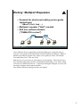
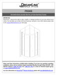
History: Multiport Repeaters
Demand for structured cabling (voice-grade
twisted-pair)
10BaseT (Cat3, Cat4, ...)
Multiport repeater ("Hub") created
Still one collision domain
("CSMA/CD in a box")
(C) Herbert Haas
2005/03/11
4
Later, Ethernet devices supporting structured cabling were created in order to
reuse the voice-grade twisted-pair cables already installed in buildings. 10BaseT
had been specified to support Cat3 cables (voice grade) or better, for example
Cat4 (and today Cat5, Cat6, and Cat7).
Hub devices were necessary to interconnect several stations. These hub devices
were basically multi-port repeaters, simulating the half-duplex coax-cable, which
is known as "CSMA/CD in a box". Logically, nothing has changed, we have still
one single collision and broadcast domain.
Note that the Ethernet topology became star-shaped.
4
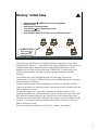
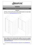
History: Bridges
Store and forwarding according destination MAC
address
Separated collision domains
Improved network performance
Still one broadcast domain
Three collision
domains in this
example !
(C) Herbert Haas
2005/03/11
5
Bridges were invented for performance reasons. It seemed to be impractical that
each additional station reduces the average per-station bandwidth by 1/n. On the
other hand the benefit of sharing a medium for communication should be still
maintained (which was expressed by Metcalfe's law).
Bridges are store and forwarding devices (introducing significant delay) that can
filter traffic based on the destination MAC addresses to avoid unnecessary
flooding of frames to certain segments. Thus, bridges segment the LAN into
several collision domains. Broadcasts are still forwarded to allow layer 3
connectivity (ARP etc), so the bridged network is still a single broadcast domain.
5
History: Switches
Switch = Multiport Bridges with HW acceleration
Full duplex
Collision-free Ethernet
No CSMA/CD
necessary anymore
Different data rates at the same time supported
Autonegotiation
VLAN splits LAN into several broadcast domains
1000 Mbit/s
Collision-free
plug & play
scalable Ethernet !
100 Mbit/s
100 Mbit/s
10 Mbit/s
(C) Herbert Haas
2005/03/11
6
Several vendors built advanced bridges, which are partly or fully implemented in
hardware. The introduced latency could be dramatically lowered and
furthermore other features were introduced, for example full duplex
communication on twisted pair cables, different frame rates on different ports,
special forwarding techniques (e,g, cut through or fragment free), Content
Addressable Memory (CAM) tables, and much more. Of course marketing rules
demand for another designation for this machine: the switch was born.
Suddenly, a collision free plug and play Ethernet was available. Simply use
twisted pair cabling only and enable autonegotiation to automatically determine
the line speed on each port (of course manual configurations would also do). This
way, switched Ethernet become very scalable.
Furthermore, Virtual LANs (VLANs) were invented to split the LAN into several
broadcast domains. VLANs improve security, utilization, and allows for logical
borders between workgroups.
6
Today
No collisions
no distance limitations !
Gigabit Ethernet becomes WAN
technology !
Over 100 km link span already
Combine several links to "Etherchannels"
Acts as single link from the spanning-tree view
• Cisco: Port Aggregation Protocol (PAgP)
• IEEE 802.1ad: Link Aggregation Control Protocol
(LACP)
1 Gbit/s or even 10 Gbit/s long reach connection !!!
(C) Herbert Haas
2005/03/11
7
Today, Gigabit and even 10 Gigabit Ethernet is available. Only twisted pair and
more and more fiber cables are used between switches, allowing full duplex
collision-free connections. Since collisions cannot occur anymore, there is no
need for a collision window anymore! From this it follows, that there is virtually
no distance limit between each two Ethernet devices.
Recent experiments demonstrated the interconnection of two Ethernet Switches
over a span of more than 100 km! Thus Ethernet became a WAN technology!
Today, many carriers use Ethernet instead of ATM/SONET/SDH or other rather
expensive technologies. GE and 10GE is relatively cheap and much simpler to
deploy. Furthermore it easily integrates into existing low-rate Ethernet
environments, allowing a homogeneous interconnection between multiple
Ethernet LAN sites. Basically, the deployment is plug and play.
If the link speed is still too slow, so-called "Etherchannels" can be configured
between each two switches by combining several ports to one logical connection.
Note that it is not possible to deploy parallel connections between two switches
without an Etherchannel configuration because the Spanning Tree Protocol (STP)
would cut off all redundant links.
Depending on the vendor, up to eight ports can be combined to constitute one
"Etherchannel".
7
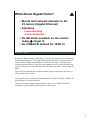
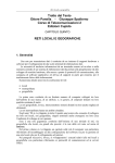
What About Gigabit Hubs?
Would limit network diameter to 2025 meters (Gigabit Ethernet)
Solutions
Frame Bursting
Carrier Extension
No GE-Hubs available on the market
today
forget it!
No CSMA/CD defined for 10GE (!)
(C) Herbert Haas
2005/03/11
8
Remember: Hubs simulate a half-duplex coaxial cable inside, hence limiting the
total network diameter. For Gigabit Ethernet this limitation would be about 25
meters, which is rather impracticable for professional usage. Although some
countermeasures had been specified in the standard, such as frame bursting and
carrier extension, no vendor developed an GE hub as for today. Thus: Forget GE
Hubs!
The 10 GE specification does neither consider copper connections nor hubs. 10
GE can only run over fiber.
At this point please remember the initial idea in the mid 1970s: Bus, CSMA/CD,
short distances, no network nodes.
Today: Structured cabling (point-to-point or star), never CSMA/CD, WAN
capabilities, sophisticated switching devices in between.
8
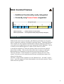
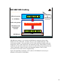
MAC Control Frames
Additional functionality easily integrated
Currently only Pause-Frame supported
Always 64 bytes
8 bytes
6
preamble
DA
6
SA
2
2
8808h
MAC-ctrl opcode
44
MAC-ctrl parameters
4
FCS
MAC-ctrl opcode ........... Defines function of control frame
MAC-ctrl parameters .... control parameter data (always filled up to 44 bytes)
(C) Herbert Haas
2005/03/11
9
Different data rates between switches (and different performance levels) often
lead to congestion conditions, full buffers, and frame drops. Traditional Ethernet
flow control was only supported on half-duplex links by enforcing collisions to
occur and hereby triggering the truncated exponential backoff algorithm. Just let
a collision occur and the aggressive sender will be silent for a while.
A much finer method is to send some dummy frames just before the backoff
timer allows sending. This way the other station never comes to send again.
Both methods are considered as ugly and only work on half duplex lines.
Therefore the MAC Control frames were specified, allowing for active flow
control. Now the receiver sends this special frame, notifying the sender to be
silent for N slot times.
The MAC Control frame originates in a new Ethernet layer—the MAC Control
Layer—and will support also other functionalities, but currently only the "Pause"
frame has been specified.
9
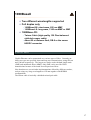
Auto Negotiation
Enables each two Ethernet devices to
exchange information about their
capabilities
Signal rate, CSMA/CD, half- or full-duplex
Using Link-Integrity-Test-Pulse-Sequence
Normal-Link-Pulse (NLP) technique is used
in 10BaseT to check the link state (green LED)
10 Mbit/s LAN devices send every 16.8 ms a
100ns lasting NLP, no signal on the wire
means disconnected
(C) Herbert Haas
2005/03/11
10
Several Ethernet operating modes had been defined, which are incompatible to
each other, including different data rates (10, 100, 1000 Mbit/s), half or full
duplex operation, MAC control frames capabilities, etc.
Original Ethernet utilized so-called Normal Link Pulses (NLPs) to verify layer 2
connectivity. NLPs are single pulses which must be received periodically
between regular frames. If NLPs are received, the green LED on the NIC is
turned on.
Newer Ethernet cards realize auto negotiation by sending a sequence of NLPs,
which is called a Fast Link Pulse (FLP) sequence.
10
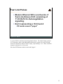
Fast Link Pulses
Modern Ethernet NICs send bursts of
Fast-Link-Pulses (FLP) consisting of
17-33 NLPs for Autonegotiation
signalling
Each representing a 16 bit word
GE sends several "pages"
(C) Herbert Haas
2005/03/11
11
A series of FLPs constitute an autonegotiation frame. The whole frame consists
of 33 timeslots, where each odd numbered timeslot consists of a real NLP and
each even timeslot is either a NLP or empty, representing 1 or 0. Thus, each FLP
sequence consists of a 16 bit word.
Note that GE Ethernet sends several such "pages".
11
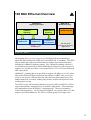
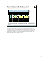
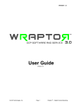
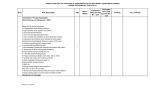
100 Mbit Ethernet Overview
IEEE 802.3u
Signaling Schemes
Fast Ethernet
100BaseX
Signaling
100BaseFX
100BaseTX
"100BaseT"
(C) Herbert Haas
2005/03/11
IEEE 802.12
Demand Priority
Fast Ethernet
100Base4T+
Signaling
100BaseT4
(half duplex)
100VG-AnyLAN
HP and AT&T
invention for real time
applications
12
The diagram above gives an overview of 100 Mbit/s Ethernet technologies,
which are differentiated into IEEE 802.3u and IEEE 802.12 standards. The IEEE
802.3u defines the widely used Fast Ethernet variants, most importantly those
utilizing the 100BaseX signaling scheme. The 100BaseX signaling consists of
several details, but basically it utilizes 4B5B block coding over only two pairs of
regular Cat 5 twisted pair cables or two strand 50/125 or 62.5/125-Fm multimode
fiber-optic cables.
100Base4T+ signaling has been specified to support 100 Mbit/s over Cat3 cables.
This mode allows half duplex operation only and uses a 8B6T code over 4 pairs
of wires; one pair for collision detection, three pairs for data transmission. One
unidirectional pair is used for sending only and two bi-directional pairs for both
sending and receiving.
The 100VG-AnyLAN technology had been created by HP and AT&T in 1992 to
support deterministic medium access for realtime applications. This technology
was standardized by the IEEE 802.12 working group. The access method is
called "demand priority". 100VG-AnyLAN supports voice grade cables (VG) but
requires special hub hardware. The 802.12 working group is no longer active.
12
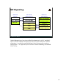
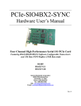
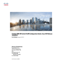
4B/5B Coding
MII
0
4 x 25
Mbit/s
0
0
16 code
groups
1
PCS
4B/5B Encoder/Decoder
0
125 MBaud
(C) Herbert Haas
1
0
0
32 code
groups
1
PMA
13
2005/03/11
The diagram above shows the basic principle of the 4B5B block coding principle,
which is used by 802.3u and also by FDDI. The basic idea is to transform any
arbitrary 4 bit word into a (relatively) balanced 5 bit word. This is done by a fast
table lookup.
Balancing the code has many advantages: better bandwidth utilization, better
laser efficiency (constant temperature), better bit-synchronization (PLL), etc.
Note that the signaling overhead is 5/4
12.5 %.
13
Gigabit Ethernet
Media Access Control (MAC)
Gigabit Media Independent Interface (GMII)
1000Base-X
8B/10B encoder/decoder
1000Base-LX
LWL
Fiber Optic
1000Base-SX
SWL
Fiber Optic
1000Base-T
encoder/decoder
1000Base-CX
Shielded
Balanced
Copper
IEEE 802.3z physical layer
(C) Herbert Haas
2005/03/11
1000Base-T
UTP
Cat 5e
IEEE 802.3ab
physical layer
14
Gigabit Ethernet has been defined in March 1996 by the working group IEEE
802.3z. The GMII represents a abstract interface between the common Ethernet
layer 2 and different signaling layers below. Two important signaling techniques
had been defines: The standard 802.3z defines 1000Base-X signaling which uses
8B10B block coding and the 802.3ab standard uses 1000Base-T signaling. The
latter is only used over twisted pair cables (UTP Cat 5 or better), while
1000BaseX is only used over fiber, with one exception, the twinax cable
(1000BaseCX), which is basically a shielded twisted pair cable.
BTW: The "X" stands for block coding.
14
GE Signaling
IEEE 802.3
Ethernet
IEEE 802.3z
Gigabit Ethernet
ANSI X3T11
Fibre Channel
802.2 LLC
IEEE 802.2 LLC
FC-4
upper layer mapping
CSMA/CD
or full duplex MAC
Reconciliation Sublayer
FC-3
common services
802.3 CSMA/CD
802.3 PHY
PCS
PHY
PMA
PMD
(C) Herbert Haas
2005/03/11
FC-2
signalling
FC-1
encoder/decoder
FC-0
interface and media
15
Gigabit Ethernet layers have been defined by adaptation of the LLC and MAC
layers of classical Ethernet and the physical layers of the ANSI Fiber Channel
technology. A so-called reconciliation layer is used in between for seamless
interoperation. The physical layer of the Fiber Channel technology uses 8B10B
block coding.
15
GE 8B/10B Coding
GMII
1
256 code groups
1
1
1
1
1
1
Only used
by
1000BaseX
1
8 x 125 Mbit/s
PCS
1024 code groups
8B/10B Encoder/Decoder
125 million code
groups per
second
1
1250 Mbaud
(C) Herbert Haas
1
1
1
1
1
1
1
1
1
PMA
2005/03/11
16
8B10B block coding is very similar to 4B5B block coding but allows fully
balanced 10-bit codewords. Actually, there are not enough balanced 10-bit
codewords available. Note that there are 256 8-bit codewords which need to be
mapped on 1024 10-bit codewords. But instead of using a fully balanced 10-bit
codeword for each 8-bit codeword, some 8-bit codewords are represented by two
10-bit codewords, which are sent in an alternating manner. That is, both
associated 10-bit words are bit-complementary.
Again, the signaling overhead is 12.5%, that is 1250 Mbaud is necessary to
transmit a bit stream of 1000 Mbit/s.
16
1000BaseX
Two different wavelengths supported
Full duplex only
1000Base-SX: short wave, 850 nm MMF
1000Base-LX: long wave, 1300 nm MMF or SMF
1000Base-CX:
Twinax Cable (high quality 150 Ohm balanced
shielded copper cable)
About 25 m distance limit, DB-9 or the newer
HSSDC connector
(C) Herbert Haas
2005/03/11
17
Gigabit Ethernet can be transmitted over various types of fiber. Currently (at
least) two types are specified, short and long wave transmissions, using 850 nm
and 1300 nm respectively. The long wave can be used with both single mode
(SMF) and multimode fibers (MMF). Only SMF can be used for WAN
transmissions because of the much lower dispersion effects.
Note that there are several other implementations offered by different vendors,
such as using very long wavelengths at 1550 nm together with DWDM
configurations.
The twinax cable is basically a shielded twisted pair cable.
17
1000BaseT
Defined by 802.3ab task force
UTP
Uses all 4 line pairs simultaneously for duplex
transmission! (echo cancellation)
5 level PAM coding
• 4 levels encode 2 bits + extra level used for Forward
Error Correction (FEC)
Signal rate: 4 x 125 Mbaud = 4 x 250Mbit/s data
rate
• Cat. 5 links, max 100 m; all 4pairs, cable must
conform to the requirements of ANSI/TIA/EIA-568-A
Only 1 CSMA/CD repeater allowed in a
collision domain
(C) Herbert Haas
2005/03/11
18
It is very difficult to transmit Gigabit speeds over unshielded twisted pair cables.
Only a mix of multiple transmission techniques ensure that this high data rate can
be transmitted over a UTP Cat5 cable. For example all 4 pairs are used together
for both directions. Echo cancellation ensures that the sending signal does not
confuse the received signal. 5 level PAM is used for encoding instead of 8B10B
because of its much lower symbol rate. Now we have only 125 Mbaud x 4
instead of 1250 Mbaud.
The interface design is very complicated and therefore relatively expensive.
Using Cat 6 or Cat 7 cables allow 500 Mbaud x 2 pairs, that is 2 pairs are
designated for TX and the other 2 pairs are used for RX. This dramatically
reduces the price but requires better cables, which are not really expensive but
slightly thicker. Legacy cable ducts might be too small in diameter.
18
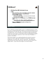
Several Physical Media Supported
Logical Link Control LLC
Data Link Layer
MAC Control (optional)
Media Access Control MAC
PLS
Reconciliation
Reconciliation
Reconciliation
MII
MII
GMII
PLS
PCS
PCS
AUI
PMA
PMA
PMA
PMD
PMD
MDI
MDI
MDI
Medium
Medium
Medium
100 Mbit/s
1000 Mbit/s
AUI
PMA (MAU)
MDI
Medium
1-10 Mbit/s
10 Mbit/s
PHY
AUI Attachment Unit Interface, PLS
Physical Layer Signaling, MDI
Medium Dependent Interface
PCS Physical Coding Sublayer, MII
Media Independent Interface, GMII
Gigabit Media Independent
Interface, PMA Physical Medium Attachment, MAU Medium Attachment Unit, PMD Physical Medium
Dependent
(C) Herbert Haas
2005/03/11
19
The diagram above shows various physical media designs supported by the
official GE standard. Each modern GE card could theoretically support the old
10 Mbit/s standard as well. However many vendors create GE NICs that only
support GE or GE and FE—who would connect a precious GE interface with
another interface, which is 100 times slower?
19
10 Gigabit Ethernet / IEEE 802.3ae
Only optical support
850nm (MM) / 1310nm /1550 nm (SM only)
No copper PHY anymore !
Different implementations at the
moment – standardization not finished!
8B/10B (IBM), SONET/SDH support, …
XAUI ("Zowie") instead of GMII
(C) Herbert Haas
2005/03/11
20
10 GE only supports optical links. Note that GE is actually a synchronous
protocol! There is no statistical multiplexing done at the physical layer anymore,
because optical switching at that bit rate only allows synchronous transmissions.
The GMII has been replaced (or enhanced) by the so-called XAUI, known as
"Zowie".
Note: At the time of writing this module, the 10 GE standard was not fully
finished. Though, some vendors already offer 10 GE interface cards for their
switches.
These interfaces are very expensive but the investment ensures backward
compatibility to lower Ethernet rates and at the same time provides a very high
speed WAN interface.
An alternative technology would be OC192, which requires a very expensive and
complex SONET/SDH environment.
20
Note
GE and 10GE use synchronous
physical sublayer !!!
Recommendation: Don't use GE over
copper wires
Radiation/EMI
Grounding problems
High BER
Thick cable bundles (especially Cat-7)
(C) Herbert Haas
2005/03/11
21
Both GE and 10GE are synchronous physical technologies on fiber. It not
recommended to use GE over copper wires anymore although 802.3ab would
specify it. This is because the whole electrical hardware (cables and connectors)
are re-used from older Ethernet technologies and have not been designed to
support such high frequencies.
For example the RJ45 connector is not HF proof. Furthermore, shielded twisted
pair cables require a very good grounding, seldom found in reality. The Bit Error
Rate (BER) is typically so high that the effective data rate is much lower than
GE, for example 30% only.
21
Summary
Ethernet evolved in the opposite direction:
Collision free
WAN qualified
Switched
Several coding styles
Complex PHY
architecture
Plug & play through autonegotiation
Much simpler than ATM but no BISDN
solution – might change!
(C) Herbert Haas
2005/03/11
22
22
Quizz
Why tends high-speed Ethernet to
synchronous PHY?
Can I attach a 100 Mbit/s port to a
1000 Mbit/s port via fiber?
What is the idea of Etherchannels?
(Maximum bit rate, difference to
multiple parallel links)
(C) Herbert Haas
2005/03/11
23
23
Hints
Q1: On fiber its difficult to deal with
asynchronous transmission, photons
cannot be buffered easily, store and
forward problems
Q2: No, autonegotiation on fiber
does not care for data rates
Q3: "normal" parallel links would be
disabled by STP, Etherchannel
supports up to 8 links
(C) Herbert Haas
2005/03/11
24
24