1
Cisco Nexus 5000 Series NX-OS Interfaces Configuration Guide,
Release 5.2(1)N1(1)
First Published: July 02, 2012
Last Modified: July 02, 2012
Americas Headquarters
Cisco Systems, Inc.
170 West Tasman Drive
San Jose, CA 95134-1706
USA
http://www.cisco.com
Tel: 408 526-4000
800 553-NETS (6387)
Fax: 408 527-0883
Text Part Number: 78-26881-OL
THE SPECIFICATIONS AND INFORMATION REGARDING THE PRODUCTS IN THIS MANUAL ARE SUBJECT TO CHANGE WITHOUT NOTICE. ALL STATEMENTS,
INFORMATION, AND RECOMMENDATIONS IN THIS MANUAL ARE BELIEVED TO BE ACCURATE BUT ARE PRESENTED WITHOUT WARRANTY OF ANY KIND,
EXPRESS OR IMPLIED. USERS MUST TAKE FULL RESPONSIBILITY FOR THEIR APPLICATION OF ANY PRODUCTS.
THE SOFTWARE LICENSE AND LIMITED WARRANTY FOR THE ACCOMPANYING PRODUCT ARE SET FORTH IN THE INFORMATION PACKET THAT SHIPPED WITH
THE PRODUCT AND ARE INCORPORATED HEREIN BY THIS REFERENCE. IF YOU ARE UNABLE TO LOCATE THE SOFTWARE LICENSE OR LIMITED WARRANTY,
CONTACT YOUR CISCO REPRESENTATIVE FOR A COPY.
The Cisco implementation of TCP header compression is an adaptation of a program developed by the University of California, Berkeley (UCB) as part of UCB's public domain version
of the UNIX operating system. All rights reserved. Copyright © 1981, Regents of the University of California.
NOTWITHSTANDING ANY OTHER WARRANTY HEREIN, ALL DOCUMENT FILES AND SOFTWARE OF THESE SUPPLIERS ARE PROVIDED “AS IS" WITH ALL FAULTS.
CISCO AND THE ABOVE-NAMED SUPPLIERS DISCLAIM ALL WARRANTIES, EXPRESSED OR IMPLIED, INCLUDING, WITHOUT LIMITATION, THOSE OF
MERCHANTABILITY, FITNESS FOR A PARTICULAR PURPOSE AND NONINFRINGEMENT OR ARISING FROM A COURSE OF DEALING, USAGE, OR TRADE PRACTICE.
IN NO EVENT SHALL CISCO OR ITS SUPPLIERS BE LIABLE FOR ANY INDIRECT, SPECIAL, CONSEQUENTIAL, OR INCIDENTAL DAMAGES, INCLUDING, WITHOUT
LIMITATION, LOST PROFITS OR LOSS OR DAMAGE TO DATA ARISING OUT OF THE USE OR INABILITY TO USE THIS MANUAL, EVEN IF CISCO OR ITS SUPPLIERS
HAVE BEEN ADVISED OF THE POSSIBILITY OF SUCH DAMAGES.
Cisco and the Cisco logo are trademarks or registered trademarks of Cisco and/or its affiliates in the U.S. and other countries. To view a list of Cisco trademarks, go to this URL: http://
www.cisco.com/go/trademarks. Third-party trademarks mentioned are the property of their respective owners. The use of the word partner does not imply a partnership
relationship between Cisco and any other company. (1110R)
Any Internet Protocol (IP) addresses used in this document are not intended to be actual addresses. Any examples, command display output, and figures included in the document are shown
for illustrative purposes only. Any use of actual IP addresses in illustrative content is unintentional and coincidental.
© 2012
Cisco Systems, Inc. All rights reserved.
CONTENTS
Preface
Preface ix
Audience ix
Document Conventions ix
Documentation Feedback x
Obtaining Documentation and Submitting a Service Request xi
CHAPTER 1
New and Changed Information for this Release 1
New and Changed Information for this Release 1
CHAPTER 2
Configuring Layer 2 Interfaces 3
Information About Ethernet Interfaces 3
About the Interface Command 3
Information About Unified Ports 4
Guidelines and Limitations for Unified Ports 4
About the Unidirectional Link Detection Parameter 5
Default UDLD Configuration 5
UDLD Aggressive and Nonaggressive Modes 6
Interface Speed 6
About the Cisco Discovery Protocol 6
Default CDP Configuration 7
About the Error-Disabled State 7
About Port Profiles 8
Guidelines and Limitations for Port Profiles 9
About the Debounce Timer Parameters 9
About MTU Configuration 9
Configuring Ethernet Interfaces 10
Configuring a Layer 3 Interface on a Cisco Nexus 5500 Platform Switch 10
Cisco Nexus 5000 Series NX-OS Interfaces Configuration Guide, Release 5.2(1)N1(1)
78-26881-OL
iii
Contents
Configuring Unified Ports 10
Configuring the UDLD Mode 12
Configuring Interface Speed 13
Disabling Link Negotiation 14
Configuring the CDP Characteristics 14
Enabling or Disabling CDP 15
Enabling the Error-Disabled Detection 16
Enabling the Error-Disabled Recovery 17
Configuring the Error-Disabled Recovery Interval 18
Port Profiles 19
Creating a Port Profile 19
Modifying a Port Profile 20
Enabling a Specific Port Profile 21
Inheriting a Port Profile 22
Removing an Inherited Port Profile 23
Assigning a Port Profile to a Range of Interfaces 24
Removing a Port Profile from a Range of Interfaces 25
Configuration Examples for Port Profiles 26
Configuring the Debounce Timer 27
Configuring the Description Parameter 28
Disabling and Restarting Ethernet Interfaces 28
Displaying Interface Information 29
Default Physical Ethernet Settings 31
CHAPTER 3
Configuring Layer 3 Interfaces 33
Information About Layer 3 Interfaces 33
Routed Interfaces 33
Subinterfaces 34
VLAN Interfaces 35
Loopback Interfaces 35
Tunnel Interfaces 36
Licensing Requirements for Layer 3 Interfaces 36
Guidelines and Limitations for Layer 3 Interfaces 36
Default Settings for Layer 3 Interfaces 36
Configuring Layer 3 Interfaces 36
Cisco Nexus 5000 Series NX-OS Interfaces Configuration Guide, Release 5.2(1)N1(1)
iv
78-26881-OL
Contents
Configuring a Routed Interface 36
Configuring a Subinterface 37
Configuring the Bandwidth on an Interface 38
Configuring a VLAN Interface 39
Configuring a Loopback Interface 40
Assigning an Interface to a VRF 40
Verifying the Layer 3 Interfaces Configuration 41
Monitoring Layer 3 Interfaces 42
Configuration Examples for Layer 3 Interfaces 43
Related Documents for Layer 3 Interfaces 44
MIBs for Layer 3 Interfaces 44
Standards for Layer 3 Interfaces 44
CHAPTER 4
Configuring Port Channels 45
Information About Port Channels 45
Understanding Port Channels 45
Guidelines and Limitations for Port Channel Configuration 46
Compatibility Requirements 47
Load Balancing Using Port Channels 48
Understanding LACP 51
LACP Overview 51
LACP ID Parameters 52
Channel Modes 52
LACP Marker Responders 53
LACP-Enabled and Static Port Channel Differences 54
Configuring Port Channels 54
Creating a Port Channel 54
Adding a Port to a Port Channel 55
Configuring Load Balancing Using Port Channels 55
Configuring Hardware Hashing for Multicast Traffic 57
Enabling LACP 57
Configuring the Channel Mode for a Port 58
Configuring the LACP Fast Timer Rate 59
Configuring the LACP System Priority and System ID 60
Configuring the LACP Port Priority 60
Cisco Nexus 5000 Series NX-OS Interfaces Configuration Guide, Release 5.2(1)N1(1)
78-26881-OL
v
Contents
Disabling LACP Graceful Convergence 61
Reenabling LACP Graceful Convergence 62
Verifying Port Channel Configuration 63
Verifying the Load-Balancing Outgoing Port ID 64
CHAPTER 5
Configuring Virtual Port Channels 65
Information About vPCs 65
vPC Overview 65
Terminology 67
vPC Terminology 67
Fabric Extender Terminology 67
Supported vPC Topologies 68
Cisco Nexus 5000 Series Switch vPC Topology 68
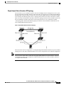
Single Homed Fabric Extender vPC Topology 69
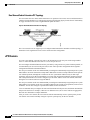
Dual Homed Fabric Extender vPC Topology 70
vPC Domain 70
Peer-Keepalive Link and Messages 71
Compatibility Parameters for vPC Peer Links 71
Configuration Parameters That Must Be Identical 71
Configuration Parameters That Should Be Identical 73
Graceful Type-1 Check 73
Per-VLAN Consistency Check 74
vPC Auto-Recovery 74
vPC Peer Links 74
vPC Peer Link Overview 74
vPC Number 75
vPC Interactions with Other Features 76
Configuring vPC Peer Links and Links to the Core 76
vPC and LACP 77
vPC Peer Links and STP 77
vPC and ARP 78
CFSoE 78
vPC Peer Switch 79
Guidelines and Limitations for vPCs 79
Configuring vPCs 80
Cisco Nexus 5000 Series NX-OS Interfaces Configuration Guide, Release 5.2(1)N1(1)
vi
78-26881-OL
Contents
Enabling vPCs 80
Disabling vPCs 80
Creating a vPC Domain 81
Configuring a vPC Keepalive Link and Messages 82
Creating a vPC Peer Link 84
Checking the Configuration Compatibility 85
Enabling vPC Auto-Recovery 86
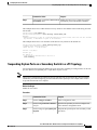
Suspending Orphan Ports on a Secondary Switch in a vPC Topology 87
Creating an EtherChannel Host Interface 88
Moving Other Port Channels into a vPC 89
Manually Configuring a vPC Domain MAC Address 90
Manually Configuring the System Priority 91
Manually Configuring a vPC Peer Switch Role 92
Configuring the vPC Peer Switch 93
Configuring a Pure vPC Peer Switch Topology 93
Configuring a Hybrid vPC Peer Switch Topology 94
Verifying the vPC Configuration 95
Viewing The Graceful Type-1 Check Status 96
Viewing A Global Type-1 Inconsistency 97
Viewing An Interface-Specific Type-1 Inconsistency 98
Viewing a Per-VLAN Consistency Status 99
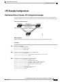
vPC Example Configurations 101
Dual Homed Fabric Extender vPC Configuration Example 101
Single Homed Fabric Extender vPC Configuration Example 103
vPC Default Settings 105
Cisco Nexus 5000 Series NX-OS Interfaces Configuration Guide, Release 5.2(1)N1(1)
78-26881-OL
vii
Contents
Cisco Nexus 5000 Series NX-OS Interfaces Configuration Guide, Release 5.2(1)N1(1)
viii
78-26881-OL
Preface
This preface contains the following sections:
• Audience, page ix
• Document Conventions, page ix
• Documentation Feedback , page x
• Obtaining Documentation and Submitting a Service Request, page xi
Audience
This publication is for experienced network administrators who configure and maintain Cisco Nexus devices
and Cisco Nexus 2000 Series Fabric Extenders.
Document Conventions
Command descriptions use the following conventions:
Convention
Description
bold
Bold text indicates the commands and keywords that you enter literally
as shown.
Italic
Italic text indicates arguments for which the user supplies the values.
[x]
Square brackets enclose an optional element(keyword or argument).
[x | y]
Square brackets enclosing keywords or arguments separated by a vertical
bar indicate an optional choice.
{x | y}
Braces enclosing keywords or arguments separated by a vertical bar
indicate a required choice.
Cisco Nexus 5000 Series NX-OS Interfaces Configuration Guide, Release 5.2(1)N1(1)
78-26881-OL
ix
Preface
Documentation Feedback
Convention
Description
[x {y | z}]
Nested set of square brackets or braces indicate optional or required
choices within optional or required elements. Braces and a vertical bar
within square brackets indicate a required choice within an optional
element.
variable
Indicates a variable for which you supply values, in context where italics
cannot be used.
string
A nonquoted set of characters. Do not use quotation marks around the
string or the string will include the quotation marks.
Examples use the following conventions:
Convention
Description
screen font
Terminal sessions and information the switch displays are in screen font.
boldface screen font
Information you must enter is in boldface screen font.
italic screen font
Arguments for which you supply values are in italic screen font.
<>
Nonprinting characters, such as passwords, are in angle brackets.
[]
Default responses to system prompts are in square brackets.
!, #
An exclamation point (!) or a pound sign (#) at the beginning of a line
of code indicates a comment line.
This document uses the following conventions:
Note
Caution
Means reader take note. Notes contain helpful suggestions or references to material not covered in the
manual.
Means reader be careful. In this situation, you might do something that could result in equipment damage
or loss of data.
Documentation Feedback
To provide technical feedback on this document, or to report an error or omission, please send your comments
to [email protected] . We appreciate your feedback.
Cisco Nexus 5000 Series NX-OS Interfaces Configuration Guide, Release 5.2(1)N1(1)
x
78-26881-OL
Preface
Obtaining Documentation and Submitting a Service Request
Obtaining Documentation and Submitting a Service Request
For information on obtaining documentation, submitting a service request, and gathering additional information,
see the monthly What's New in Cisco Product Documentation, which also lists all new and revised Cisco
technical documentation, at:
http://www.cisco.com/en/US/docs/general/whatsnew/whatsnew.html
Subscribe to the What's New in Cisco Product Documentation as a Really Simple Syndication (RSS) feed
and set content to be delivered directly to your desktop using a reader application. The RSS feeds are a free
service and Cisco currently supports RSS version 2.0.
Cisco Nexus 5000 Series NX-OS Interfaces Configuration Guide, Release 5.2(1)N1(1)
78-26881-OL
xi
Preface
Obtaining Documentation and Submitting a Service Request
Cisco Nexus 5000 Series NX-OS Interfaces Configuration Guide, Release 5.2(1)N1(1)
xii
78-26881-OL
CHAPTER
1
New and Changed Information for this Release
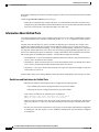
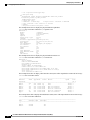
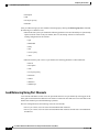
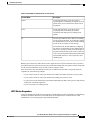
The following table provides an overview of the significant changes to this guide for this current release.
The table does not provide an exhaustive list of all changes made to the configuration guides or of the new
features in this release.
• New and Changed Information for this Release, page 1
New and Changed Information for this Release
The following table provides an overview of the significant changes to this guide for this current release. The
table does not provide an exhaustive list of all changes made to the configuration guides or of the new features
in this release.
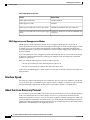
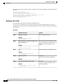
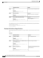
Table 1: New Features
Feature
Description
IPv6
Added support for IPv6 addressing.
Where Documented
• Routed Interfaces, on page
33
• Configuring a Subinterface,
on page 37
• Configuring the Bandwidth
on an Interface, on page 38
• Configuring a VLAN
Interface, on page 39
• Configuring a Loopback
Interface, on page 40
• Assigning an Interface to a
VRF, on page 40
Cisco Nexus 5000 Series NX-OS Interfaces Configuration Guide, Release 5.2(1)N1(1)
78-26881-OL
1
New and Changed Information for this Release
New and Changed Information for this Release
Cisco Nexus 5000 Series NX-OS Interfaces Configuration Guide, Release 5.2(1)N1(1)
2
78-26881-OL
CHAPTER
2
Configuring Layer 2 Interfaces
This chapter contains the following sections:
• Information About Ethernet Interfaces, page 3
• Configuring Ethernet Interfaces, page 10
• Displaying Interface Information, page 29
• Default Physical Ethernet Settings , page 31
Information About Ethernet Interfaces
The Ethernet ports can operate as standard Ethernet interfaces connected to servers or to a LAN.
The Ethernet interfaces also support Fibre Channel over Ethernet (FCoE). FCoE allows the physical Ethernet
link to carry both Ethernet and Fibre Channel traffic.
The Ethernet interfaces are enabled by default.
About the Interface Command
You can enable the various capabilities of the Ethernet interfaces on a per-interface basis using the interface
command. When you enter the interface command, you specify the following information:
• Interface type—All physical Ethernet interfaces use the ethernet keyword.
• Slot number
◦ Slot 1 includes all the fixed ports.
◦ Slot 2 includes the ports on the upper expansion module (if populated).
◦ Slot 3 includes the ports on the lower expansion module (if populated).
◦ Slot 4 includes the ports on the lower expansion module (if populated).
• Port number— Port number within the group.
Cisco Nexus 5000 Series NX-OS Interfaces Configuration Guide, Release 5.2(1)N1(1)
78-26881-OL
3
Configuring Layer 2 Interfaces
Information About Unified Ports
The interface numbering convention is extended to support use with a Cisco Nexus 2000 Series Fabric Extender
as follows:
switch(config)# interface ethernet [chassis/]slot/port
• Chassis ID is an optional entry to address the ports of a connected Fabric Extender. The chassis ID is
configured on a physical Ethernet or EtherChannel interface on the switch to identify the Fabric Extender
discovered via the interface. The chassis ID ranges from 100 to 199.
Information About Unified Ports
Cisco Nexus unified ports allow you to configure a physical port on a Cisco Nexus 5500 Platform switch as
a 1/10-Gigabit Ethernet, Fibre Channel over Ethernet (FCoE), or 1-, 2-, 4-, 8-Gigabit native Fibre Channel
port.
Currently, most networks have two types of switches for different types of networks. For example, LAN
switches carry Ethernet traffic up to Catalyst switches and SAN switches carry FC traffic from servers to
MDS switches. With unified port technology, you can deploy a unified platform, unified device, and unified
wire approach. Unified ports allow you to move from an existing segregated platform approach where you
choose LAN and SAN port options to transition to a single, unified fabric that is transparent and consistent
with existing practices and management software. A unified fabric includes the following:
• Unified platform—Uses the same hardware platform and the same software code level and certifies it
once for your LAN and SAN environments.
• Unified device—Runs LAN and SAN services on the same platform switch. The unified device allows
you to connect your Ethernet and Fibre Channel cables to the same device.
• Unified wire—Converges LAN and SAN networks on a single converged network adapter (CNA) and
connects them to your server.
A unified fabric allows you to manage Ethernet and FCoE features independently with existing Cisco tools.
Guidelines and Limitations for Unified Ports
• Ethernet ports and Fibre Channel ports must be configured in the following order:
• Fibre Channel ports must be configured from the last port of the module.
• Ethernet ports must be configured from the first port of the module.
If the order is not followed, the following errors are displayed:
ERROR: Ethernet range starts from first port of the module
ERROR: FC range should end on last port of the module
• On the Cisco Nexus 5548UP switch, the 32 ports of the main slot (slot1) are unified ports. The Ethernet
ports start from port 1/1 to port 1/32. The Fibre Channel ports start from port 1/32 backwards to port
1/1.
• For the Cisco Nexus 5596T switch, the last 16 ports (ports 33-48) are Fiber Channel and are configurable
as unified ports. The first 32 ports (1-32) are 10GBase-T Ethernet ports only and cannot be configured
as unified ports.
Cisco Nexus 5000 Series NX-OS Interfaces Configuration Guide, Release 5.2(1)N1(1)
4
78-26881-OL
Configuring Layer 2 Interfaces
About the Unidirectional Link Detection Parameter
About the Unidirectional Link Detection Parameter
The Cisco-proprietary Unidirectional Link Detection (UDLD) protocol allows ports that are connected through
fiber optics or copper (for example, Category 5 cabling) Ethernet cables to monitor the physical configuration
of the cables and detect when a unidirectional link exists. When the switch detects a unidirectional link, UDLD
shuts down the affected LAN port and alerts the user. Unidirectional links can cause a variety of problems,
including spanning tree topology loops.
UDLD is a Layer 2 protocol that works with the Layer 1 protocols to determine the physical status of a link.
At Layer 1, autonegotiation takes care of physical signaling and fault detection. UDLD performs tasks that
autonegotiation cannot perform, such as detecting the identities of neighbors and shutting down misconnected
LAN ports. When you enable both autonegotiation and UDLD, Layer 1 and Layer 2 detections work together
to prevent physical and logical unidirectional connections and the malfunctioning of other protocols.
A unidirectional link occurs whenever traffic transmitted by the local device over a link is received by the
neighbor but traffic transmitted from the neighbor is not received by the local device. If one of the fiber strands
in a pair is disconnected, as long as autonegotiation is active, the link does not stay up. In this case, the logical
link is undetermined, and UDLD does not take any action. If both fibers are working normally at Layer 1,
then UDLD at Layer 2 determines whether those fibers are connected correctly and whether traffic is flowing
bidirectionally between the correct neighbors. This check cannot be performed by autonegotiation, because
autonegotiation operates at Layer 1.
A Cisco Nexus device periodically transmits UDLD frames to neighbor devices on LAN ports with UDLD
enabled. If the frames are echoed back within a specific time frame and they lack a specific acknowledgment
(echo), the link is flagged as unidirectional and the LAN port is shut down. Devices on both ends of the link
must support UDLD in order for the protocol to successfully identify and disable unidirectional links.
Note
By default, UDLD is locally disabled on copper LAN ports to avoid sending unnecessary control traffic
on this type of media.
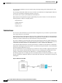
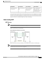
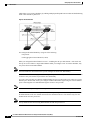
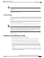
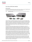
The following figure shows an example of a unidirectional link condition. Device B successfully receives
traffic from Device A on the port. However, Device A does not receive traffic from Device B on the same
port. UDLD detects the problem and disables the port.
Figure 1: Unidirectional Link
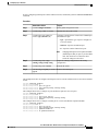
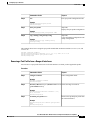
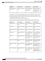
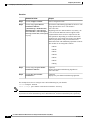
Default UDLD Configuration
The following table shows the default UDLD configuration.
Cisco Nexus 5000 Series NX-OS Interfaces Configuration Guide, Release 5.2(1)N1(1)
78-26881-OL
5
Configuring Layer 2 Interfaces
Interface Speed
Table 2: UDLD Default Configuration
Feature
Default Value
UDLD global enable state
Globally disabled
UDLD aggressive mode
Disabled
UDLD per-port enable state for fiber-optic media
Enabled on all Ethernet fiber-optic LAN ports
UDLD per-port enable state for twisted-pair (copper) Disabled on all Ethernet 10/100 and 1000BASE-TX
media
LAN ports
UDLD Aggressive and Nonaggressive Modes
UDLD aggressive mode is disabled by default. You can configure UDLD aggressive mode only on
point-to-point links between network devices that support UDLD aggressive mode. If UDLD aggressive mode
is enabled, when a port on a bidirectional link that has a UDLD neighbor relationship established stops
receiving UDLD frames, UDLD tries to reestablish the connection with the neighbor. After eight failed retries,
the port is disabled.
To prevent spanning tree loops, nonaggressive UDLD with the default interval of 15 seconds is fast enough
to shut down a unidirectional link before a blocking port transitions to the forwarding state (with default
spanning tree parameters).
When you enable the UDLD aggressive mode, the following occurs:
• One side of a link has a port stuck (both transmission and receive)
• One side of a link remains up while the other side of the link is down
In these cases, the UDLD aggressive mode disables one of the ports on the link, which prevents traffic from
being discarded.
Interface Speed
The 5596T switch has 48 base board ports and 3 GEM slots. The first 32 ports are 10GBase-T ports the last
16 ports are SFP+ ports. The 10GBase-T ports support a speed of 1-Gigabit, 10-Gigabit, or Auto. The Auto
setting automatically negotiates with the link parser to select either 1-Gigabit or 10-Gigabit speed.
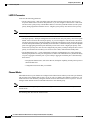
About the Cisco Discovery Protocol
The Cisco Discovery Protocol (CDP) is a device discovery protocol that runs over Layer 2 (the data link layer)
on all Cisco-manufactured devices (routers, bridges, access servers, and switches) and allows network
management applications to discover Cisco devices that are neighbors of already known devices. With CDP,
network management applications can learn the device type and the Simple Network Management Protocol
(SNMP) agent address of neighboring devices running lower-layer, transparent protocols. This feature enables
applications to send SNMP queries to neighboring devices.
Cisco Nexus 5000 Series NX-OS Interfaces Configuration Guide, Release 5.2(1)N1(1)
6
78-26881-OL
Configuring Layer 2 Interfaces
About the Error-Disabled State
CDP runs on all media that support Subnetwork Access Protocol (SNAP). Because CDP runs over the data-link
layer only, two systems that support different network-layer protocols can learn about each other.
Each CDP-configured device sends periodic messages to a multicast address, advertising at least one address
at which it can receive SNMP messages. The advertisements also contain time-to-live, or holdtime information,
which is the length of time a receiving device holds CDP information before discarding it. Each device also
listens to the messages sent by other devices to learn about neighboring devices.
The switch supports both CDP Version 1 and Version 2.
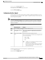
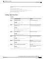
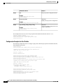
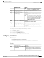
Default CDP Configuration
The following table shows the default CDP configuration.
Table 3: Default CDP Configuration
Feature
Default Setting
CDP interface state
Enabled
CDP timer (packet update frequency)
60 seconds
CDP holdtime (before discarding)
180 seconds
CDP Version-2 advertisements
Enabled
About the Error-Disabled State
An interface is in the error-disabled (err-disabled) state when the inteface is enabled administratively (using
the no shutdown command) but disabled at runtime by any process. For example, if UDLD detects a
unidirectional link, the interface is shut down at runtime. However, because the interface is administratively
enabled, the interface status displays as err-disabled. Once an interface goes into the err-disabled state, you
must manually reenable it or you can configure an automatic timeout recovery value. The err-disabled detection
is enabled by default for all causes. The automatic recovery is not configured by default.
When an interface is in the err-disabled state, use the errdisable detect cause command to find information
about the error.
You can configure the automatic err-disabled recovery timeout for a particular err-disabled cause by changing
the time variable.
The errdisable recovery cause command provides automatic recovery after 300 seconds. To change the
recovery period, use the errdisable recovery interval command to specify the timeout period. You can specify
30 to 65535 seconds.
If you do not enable the err-disabled recovery for the cause, the interface stays in the err-disabled state until
you enter the shutdown and no shutdown commands. If the recovery is enabled for a cause, the interface is
brought out of the err-disabled state and allowed to retry operation once all the causes have timed out. Use
the show interface status err-disabled command to display the reason behind the error.
Cisco Nexus 5000 Series NX-OS Interfaces Configuration Guide, Release 5.2(1)N1(1)
78-26881-OL
7
Configuring Layer 2 Interfaces
About Port Profiles
About Port Profiles
You can create a port profile that contains many interface commands and apply that port profile to a range of
interfaces on the Cisco Nexus device. Port profiles can be applied to the following interface types:
• Ethernet
• VLAN network interface
• Port channel
A command that is included in a port profile can be configured outside of the port profile. If the new
configuration in the port profile conflicts with the configurations that exist outside the port profile, the
commands configured for an interface in configuration terminal mode have higher priority than the commands
in the port profile. If changes are made to the interface configuration after a port profile is attached to it, and
the configuration conflicts with that in the port profile, the configurations in the interface will be given priority.
You inherit the port profile when you attach the port profile to an interface or range of interfaces, When you
attach, or inherit, a port profile to an interface or range of interfaces, the switch applies all the commands in
that port profile to the interfaces.
You can have one port profile inherit the settings from another port profile. Inheriting another port profile
allows the initial port profile to assume all of the commands of the second, inherited, port profile that do not
conflict with the initial port profile. Four levels of inheritance are supported. The same port profile can be
inherited by any number of port profiles.
To apply the port profile configurations to the interfaces, you must enable the specific port profile. You can
configure and inherit a port profile onto a range of interfaces prior to enabling the port profile; you then enable
that port profile for the configurations to take effect on the specified interfaces.
When you remove a port profile from a range of interfaces, the switch undoes the configuration from the
interfaces first and then removes the port profile link itself. When you remove a port profile, the switch checks
the interface configuration and either skips the port profile commands that have been overridden by directly
entered interface commands or returns the command to the default value.
If you want to delete a port profile that has been inherited by other port profiles, you must remove the inheritance
before you can delete the port profile.
You can choose a subset of interfaces from which to remove a port profile from among that group of interfaces
that you originally applied the profile. For example, if you configured a port profile and configured ten
interfaces to inherit that port profile, you can remove the port profile from just some of the specified ten
interfaces. The port profile continues to operate on the remaining interfaces to which it is applied.
If you delete a specific configuration for a specified range of interfaces using the interface configuration mode,
that configuration is also deleted from the port profile for that range of interfaces only. For example, if you
have a channel group inside a port profile and you are in the interface configuration mode and you delete that
port channel, the specified port channel is also deleted from the port profile as well.
After you inherit a port profile on an interface or range of interfaces and you delete a specific configuration
value, that port profile configuration will not operate on the specified interfaces.
If you attempt to apply a port profile to the wrong type of interface, the switch returns an error.
When you attempt to enable, inherit, or modify a port profile, the switch creates a checkpoint. If the port
profile configuration fails, the switch rolls back to the prior configuration and returns an error. A port profile
is never only partially applied.
Cisco Nexus 5000 Series NX-OS Interfaces Configuration Guide, Release 5.2(1)N1(1)
8
78-26881-OL
Configuring Layer 2 Interfaces
About the Debounce Timer Parameters
Guidelines and Limitations for Port Profiles
Port profiles have the following configuration guidelines and limitations:
• Each port profile must have a unique name across interface types and the network.
• Commands that you enter under the interface mode take precedence over the port profile’s commands
if there is a conflict. However, the port profile retains that command in the port profile.
• The port profile’s commands take precedence over the default commands on the interface, unless the
default command explicitly overrides the port profile command.
• After you inherit a port profile onto an interface or range of interfaces, you can override individual
configuration values by entering the new value at the interface configuration level. If you remove the
individual configuration values at the interface configuration level, the interface uses the values in the
port profile again.
• There are no default configurations associated with a port profile.
• A subset of commands are available under the port profile configuration mode, depending on which
interface type that you specify.
• You cannot use port profiles with Session Manager.
About the Debounce Timer Parameters
The port debounce time is the amount of time that an interface waits to notify the supervisor of a link going
down. During this time, the interface waits to see if the link comes back up. The wait period is a time when
traffic is stopped.
You can enable the debounce timer for each interface and specify the delay time in milliseconds.
Caution
When you enable the port debounce timer the link up and link down detections are delayed, resulting in
a loss of traffic during the debounce period. This situation might affect the convergence and reconvergence
of some protocols.
About MTU Configuration
The Cisco Nexus device switch does not fragment frames. As a result, the switch cannot have two ports in
the same Layer 2 domain with different maximum transmission units (MTUs). A per-physical Ethernet interface
MTU is not supported. Instead, the MTU is set according to the QoS classes. You modify the MTU by setting
class and policy maps.
Note
When you show the interface settings, a default MTU of 1500 is displayed for physical Ethernet interfaces
and a receive data field size of 2112 is displayed for Fibre Channel interfaces.
Cisco Nexus 5000 Series NX-OS Interfaces Configuration Guide, Release 5.2(1)N1(1)
78-26881-OL
9
Configuring Layer 2 Interfaces
Configuring Ethernet Interfaces
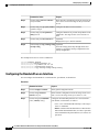
Configuring Ethernet Interfaces
The section includes the following topics:
Configuring a Layer 3 Interface on a Cisco Nexus 5500 Platform Switch
On Cisco Nexus devices, you can configure a Layer 3 interface.
You can change a Layer 3 interface into a Layer 2 interface by using the switchport command. You can
change a Layer 2 interface into a Layer 3 interface by using the no switchport command.
Note
Procedure
Command or Action
Purpose
Step 1
switch# configure terminal
Enters configuration mode.
Step 2
switch(config)# interface ethernet slot/port Enters configuration mode for the specified
interface.
Step 3
switch(config-if)# no switchport
Selects the Layer 3 interface.
Step 4
switch(config-if)# no shutdown
Restarts the interface.
This example shows how to configure a Layer 3 interface:
switch# configure terminal
switch(config)# interface ethernet 1/2
switch(config-if)# no switchport
switch(config-if)# no shutdown
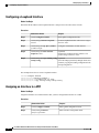
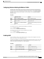
Configuring Unified Ports
Before You Begin
Confirm that you have a supported Cisco Nexus switch. Unified Ports are available on the following Cisco
Nexus switches:
• Cisco Nexus 5596T
• Cisco Nexus 5548UP
• Cisco Nexus 5596UP
• Cisco Nexus 5548P switch with an installed Cisco N55-M16UP expansion module
Cisco Nexus 5000 Series NX-OS Interfaces Configuration Guide, Release 5.2(1)N1(1)
10
78-26881-OL
Configuring Layer 2 Interfaces
Configuring Unified Ports
If you're configuring a unified port as Fibre Channel or FCoE, confirm that you have enabled the feature fcoe
command.
Procedure
Command or Action
Purpose
Step 1
switch# configure terminal
Enters global configuration mode.
Step 2
switch(config) # slot slot number
Identifies the slot on the switch.
Step 3
switch(config-slot) # port port
number type {ethernet | fc}
Configures a unified port as a native Fibre Channel port
and an Ethernet port.
• type—Specifies the type of port to configure on
a slot in a chassis.
• ethernet—Specifies an Ethernet port.
• fc—Specifies a Fibre Channel (FC) port.
Note
Changing unified ports on an expansion module
(GEM) requires that you power cycle the GEM
card. You do not have to reboot the entire
switch for changes to take effect.
Step 4
switch(config-slot) # copy
running-config startup-config
Copies the running configuration to the startup
configuration.
Step 5
switch(config-slot) # reload
Reboots the switch.
Step 6
switch(config) # no port port number Removes the unified port.
type fc
This example shows how to configure a unified port on a Cisco Nexus 5548UP switch or Cisco Nexus 5596UP
switch:
switch# configure terminal
switch(config)# slot 1
switch(config-slot)# port 32 type fc
switch(config-slot)# copy running-config startup-config
switch(config-slot)# reload
This example shows how to configure 20 ports as Ethernet ports and 12 as FC ports:
switch# configure terminal
switch(config)# slot 1
switch(config-slot)# port 21-32 type fc
switch(config-slot)# copy running-config startup-config
switch(config-slot)# reload
This example shows how to configure a unified port on a Cisco N55-M16UP expansion module:
switch# configure terminal
switch(config)# slot 2
switch(config-slot)# port 16 type fc
switch(config-slot)# copy running-config startup-config
switch(config-slot)# poweroff module 2
switch(config-slot)# no poweroff module 2
Cisco Nexus 5000 Series NX-OS Interfaces Configuration Guide, Release 5.2(1)N1(1)
78-26881-OL
11
Configuring Layer 2 Interfaces
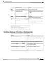
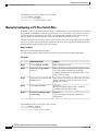
Configuring the UDLD Mode
Configuring the UDLD Mode
You can configure normal or aggressive unidirectional link detection (UDLD) modes for Ethernet interfaces
on devices configured to run UDLD. Before you can enable a UDLD mode for an interface, you must make
sure that UDLD is already enabled on the device that includes the interface. UDLD must also be enabled on
the other linked interface and its device.
To use the normal UDLD mode, you must configure one of the ports for normal mode and configure the other
port for the normal or aggressive mode. To use the aggressive UDLD mode, you must configure both ports
for the aggressive mode.
Note
Before you begin, UDLD must be enabled for the other linked port and its device.
Procedure
Command or Action
Purpose
Step 1
switch# configure terminal
Enters configuration mode.
Step 2
switch(config)# feature udld
Enables UDLD for the device.
Step 3
switch(config)# no feature udld
Disables UDLD for the device.
Step 4
switch(config)# show udld global
Displays the UDLD status for the device.
Step 5
switch(config)# interface type slot/port
Specifies an interface to configure, and enters
interface configuration mode.
Step 6
switch(config-if)# udld {enable | disable Enables the normal UDLD mode, disables
UDLD, or enables the aggressive UDLD mode.
| aggressive}
Step 7
switch(config-if)# show udld interface
Displays the UDLD status for the interface.
This example shows how to enable the UDLD for the switch:
switch# configure terminal
switch(config)# feature udld
This example shows how to enable the normal UDLD mode for an Ethernet port:
switch# configure terminal
switch(config)# interface ethernet 1/4
switch(config-if)# udld enable
This example shows how to enable the aggressive UDLD mode for an Ethernet port:
switch# configure terminal
switch(config)# interface ethernet 1/4
switch(config-if)# udld aggressive
This example shows how to disable UDLD for an Ethernet port:
switch# configure terminal
Cisco Nexus 5000 Series NX-OS Interfaces Configuration Guide, Release 5.2(1)N1(1)
12
78-26881-OL
Configuring Layer 2 Interfaces
Configuring Interface Speed
switch(config)# interface ethernet 1/4
switch(config-if)# udld disable
This example shows how to disable UDLD for the switch:
switch# configure terminal
switch(config)# no feature udld
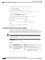
Configuring Interface Speed
The first 32 ports of a Cisco Nexus 5596T switch are switchable 1-Gigabit and 10-Gigabit ports. You can
also configure them to auto-negotiate to either 1-Gigabit or 10-Gigabit. The last ports 33-48 are SFP+ ports
and do not support auto negotiation.
Note
If the interface and transceiver speed is mismatched, the SFP validation failed message is displayed when
you enter the show interface ethernet slot/port command. For example, if you insert a 1-Gigabit SFP
transceiver into a port without configuring the speed 1000 command, you will get this error. By default,
all ports are 10 Gigabits.
Procedure
Command or Action
Purpose
Step 1
switch# configure terminal Enters global configuration mode.
Step 2
switch(config)# interface
type slot/port
Enters interface configuration mode for the specified interface.
This interface must have a 1-Gigabit Ethernet SFP transceiver
inserted into it.
Step 3
switch(config-if)# speed
speed
Sets the speed for a physical Ethernet interface.
For Cisco Nexus 5500 series switches, the speed argument can be
set to one of the following:
• 1000—1 Gbps
• 10000—10Gbps
• auto
Note
100 Mbps is not a supported speed for the Cisco Nexus
5596 switch or CU-96 GEM card.
For the Cisco Nexus 5596T switch, the base board ports
support 1 Gbps and 10 Gbps. On the 10GBase-T ports
you can also choose auto.
The following example shows how to set the speed for a 1-Gigabit Ethernet port:
switch# configure terminal
switch(config)# interface ethernet 1/4
switch(config-if)# speed 1000
Cisco Nexus 5000 Series NX-OS Interfaces Configuration Guide, Release 5.2(1)N1(1)
78-26881-OL
13
Configuring Layer 2 Interfaces
Disabling Link Negotiation
Disabling Link Negotiation
You can disable link negotiation using the no negotiate auto command. By default, auto-negotiation is enabled
on 1-Gigabit ports and disabled on 10-Gigabit ports.
This command is equivalent to the Cisco IOS speed non-negotiate command.
Note
We do not recommend that you enable auto negotiation on 10-Gigabit ports. Enabling auto-negotiation
on 10-Gigabit ports brings the link down. By default, link negotiation is disabled on 10-Gigabit ports.
Procedure
Command or Action
Purpose
Step 1
switch# configure terminal
Enters configuration mode.
Step 2
switch(config)# interface ethernet
slot/port
Selects the interface and enters interface mode.
Step 3
switch(config-if)# no negotiate auto Disables link negotiation on the selected Ethernet
interface (1-Gigabit port).
Step 4
switch(config-if)# negotiate auto
(Optional)
Enables link negotiation on the selected Ethernet
interface. The default for 1-Gigabit ports is enabled.
Note
This command is not applicable for 10GBase-T
ports. It should not be used on 10GBase-T ports.
This example shows how to disable auto negotiation on a specified Ethernet interface (1-Gigabit port):
switch# configure terminal
switch(config)# interface ethernet 1/1
switch(config-if)# no negotiate auto
switch(config-if)#
This example shows how to enable auto negotiation on a specified Ethernet interface (1-Gigabit port):
switch# configure terminal
switch(config)# interface ethernet 1/5
switch(config-if)# negotiate auto
switch(config-if)#
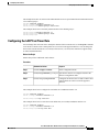
Configuring the CDP Characteristics
You can configure the frequency of Cisco Discovery Protocol (CDP) updates, the amount of time to hold the
information before discarding it, and whether or not to send Version-2 advertisements.
Cisco Nexus 5000 Series NX-OS Interfaces Configuration Guide, Release 5.2(1)N1(1)
14
78-26881-OL
Configuring Layer 2 Interfaces
Enabling or Disabling CDP
Procedure
Command or Action
Purpose
Step 1
switch# configure terminal
Enters configuration mode.
Step 2
switch(config)# [no] cdp
advertise {v1 | v2 }
(Optional)
Configures the version to use to send CDP advertisements.
Version-2 is the default state.
Use the no form of the command to return to its default
setting.
Step 3
switch(config)# [no] cdp format (Optional)
Configures the format of the CDP device ID. The default is
device-id {mac-address |
serial-number | system-name} the system name, which can be expressed as a fully qualified
domain name.
Use the no form of the command to return to its default
setting.
Step 4
switch(config)# [no] cdp
holdtime seconds
(Optional)
Specifies the amount of time a receiving device should hold
the information sent by your device before discarding it. The
range is 10 to 255 seconds; the default is 180 seconds.
Use the no form of the command to return to its default
setting.
Step 5
switch(config)# [no] cdp timer
seconds
(Optional)
Sets the transmission frequency of CDP updates in seconds.
The range is 5 to 254; the default is 60 seconds.
Use the no form of the command to return to its default
setting.
This example shows how to configure CDP characteristics:
switch# configure terminal
switch(config)# cdp timer 50
switch(config)# cdp holdtime 120
switch(config)# cdp advertise v2
Enabling or Disabling CDP
You can enable or disable CDP for Ethernet interfaces. This protocol works only when you have it enabled
on both interfaces on the same link.
Cisco Nexus 5000 Series NX-OS Interfaces Configuration Guide, Release 5.2(1)N1(1)
78-26881-OL
15
Configuring Layer 2 Interfaces
Enabling the Error-Disabled Detection
Procedure
Command or Action
Purpose
Step 1
switch# configure terminal
Enters configuration mode.
Step 2
switch(config)# interface type slot/port Enters interface configuration mode for the specified
interface.
Step 3
switch(config-if)# cdp enable
Enables CDP for the interface.
To work correctly, this parameter must be enabled
for both interfaces on the same link.
Step 4
switch(config-if)# no cdp enable
Disables CDP for the interface.
This example shows how to enable CDP for an Ethernet port:
switch# configure terminal
switch(config)# interface ethernet 1/4
switch(config-if)# cdp enable
This command can only be applied to a physical Ethernet interface.
Enabling the Error-Disabled Detection
You can enable error-disable (err-disabled) detection in an application. As a result, when a cause is detected
on an interface, the interface is placed in an err-disabled state, which is an operational state that is similar to
the link-down state.
Procedure
Step 1
Command or Action
Purpose
config t
Enters configuration mode.
Example:
switch# config t
switch(config)#
Step 2
errdisable detect cause {all | link-flap |
loopback}
Specifies a condition under which to place the
interface in an err-disabled state. The default is
enabled.
Example:
switch(config)# errdisable detect cause
all
switch(config)#
Step 3
shutdown
Example:
Brings the interface down administratively. To
manually recover the interface from the
err-disabled state, enter this command first.
switch(config)# shutdown
switch(config)#
Cisco Nexus 5000 Series NX-OS Interfaces Configuration Guide, Release 5.2(1)N1(1)
16
78-26881-OL
Configuring Layer 2 Interfaces
Enabling the Error-Disabled Recovery
Step 4
Command or Action
Purpose
no shutdown
Brings the interface up administratively and
enables the interface to recover manually from
the err-disabled state.
Example:
switch(config)# no shutdown
switch(config)#
Step 5
show interface status err-disabled
Displays information about err-disabled
interfaces.
Example:
switch(config)# show interface status
err-disabled
Step 6
copy running-config startup-config
(Optional) Copies the running configuration to
the startup configuration.
Example:
switch(config)# copy running-config
startup-config
This example shows how to enable the err-disabled detection in all cases:
switch(config)#errdisable detect cause all
switch(config)#
Enabling the Error-Disabled Recovery
You can specify the application to bring the interface out of the error-disabled (err-disabled) state and retry
coming up. It retries after 300 seconds, unless you configure the recovery timer (see the errdisable recovery
interval command).
Procedure
Step 1
Command or Action
Purpose
config t
Enters configuration mode.
Example:
switch#config t
switch(config)#
Step 2
errdisable recovery cause {all | udld |
bpduguard | link-flap | failed-port-state |
pause-rate-limit}
Example:
Specifies a condition under which the interface
automatically recovers from the err-disabled
state, and the device retries bringing the
interface up. The device waits 300 seconds to
retry. The default is disabled.
switch(config)#errdisable recovery cause
all
switch(config-if)#
Cisco Nexus 5000 Series NX-OS Interfaces Configuration Guide, Release 5.2(1)N1(1)
78-26881-OL
17
Configuring Layer 2 Interfaces
Configuring the Error-Disabled Recovery Interval
Step 3
Command or Action
Purpose
show interface status err-disabled
Displays information about err-disabled
interfaces.
Example:
switch(config)#show interface status
err-disabled
Step 4
copy running-config startup-config
(Optional) Copies the running configuration to
the startup configuration.
Example:
switch(config)#copy running-config
startup-config
This example shows how to enable err-disabled recovery under all conditions:
switch(config)#errdisable recovery cause all
switch(config)#
Configuring the Error-Disabled Recovery Interval
You can use this procedure to configure the err-disabled recovery timer value. The range is from 30 to 65535
seconds. The default is 300 seconds.
Procedure
Step 1
Command or Action
Purpose
config t
Enters configuration mode.
Example:
switch#config t
switch(config)#
Step 2
errdisable recovery interval interval
Example:
switch(config)#errdisable recovery
interval 32
switch(config-if)#
Step 3
show interface status err-disabled
Specifies the interval for the interface to
recover from the err-disabled state. The range
is from 30 to 65535 seconds. The default is
300 seconds.
Displays information about err-disabled
interfaces.
Example:
switch(config)#show interface status
err-disabled
Step 4
copy running-config startup-config
(Optional) Copies the running configuration
to the startup configuration.
Example:
switch(config)#copy running-config
startup-config
Cisco Nexus 5000 Series NX-OS Interfaces Configuration Guide, Release 5.2(1)N1(1)
18
78-26881-OL
Configuring Layer 2 Interfaces
Port Profiles
This example shows how to enable err-disabled recovery under all conditions:
switch(config)#errdisable recovery cause all
switch(config)#
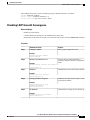
Port Profiles
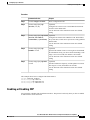
Creating a Port Profile
You can create a port profile on the switch. Each port profile must have a unique name across interface types
and the network.
Procedure
Step 1
Command or Action
Purpose
configure terminal
Enters configuration mode.
Example:
switch# configure terminal
switch(config)#
Step 2
port-profile [type {ethernet | interface-vlan |
port channel}] name
Creates and names a port profile for the
specified type of interface and enters the
port profile configuration mode.
Example:
switch(config)# port-profile type ethernet
test
switch(config-port-prof)#
Step 3
Exits port profile configuration mode.
exit
Example:
switch(config-port-prof)# exit
switch(config)#
Step 4
show port-profile
(Optional)
Displays the port profile configuration.
Example:
switch(config)# show port-profile name
Step 5
copy running-config startup-config
Example:
(Optional)
Copies the running configuration to the
startup configuration.
switch(config)# copy running-config
startup-config
This example shows how to create a port profile named test for Ethernet interfaces:
switch# configure terminal
switch(config)# port-profile type ethernet test
switch(config-port-prof)#
Cisco Nexus 5000 Series NX-OS Interfaces Configuration Guide, Release 5.2(1)N1(1)
78-26881-OL
19
Configuring Layer 2 Interfaces
Port Profiles
This example shows how to add the interface commands to a port profile named ppEth configured for Ethernet
interfaces:
switch# configure terminal
switch(config)# port-profile ppEth
switch(config-port-prof)# switchport mode trunk
switch(config-port-prof)# switchport trunk allowed vlan 300-400
switch(config-port-prof)# flowcontrol receive on
switch(config-port-prof)# speed 10000
switch(config-port-prof)#
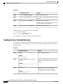
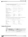
Modifying a Port Profile
You can modify a port profile in port-profile configuration mode.
You can remove commands from a port profile using the no form of the command. When you remove a
command from the port profile, the corresponding command is removed from the interface that is attached to
the port profile.
Procedure
Step 1
Command or Action
Purpose
configure terminal
Enters configuration mode.
Example:
switch# configure terminal
switch(config)#
Step 2
port-profile [type {ethernet | interface-vlan |
port channel}] name
Example:
Enters the port profile configuration mode
for the specified port profile and allows you
to add or remove configurations to the
profile.
switch(config)# port-profile type ethernet
test
switch(config-port-prof)#
Step 3
exit
Exits the port profile configuration mode.
Example:
switch(config-port-prof)# exit
switch(config)#
Step 4
show port-profile
(Optional)
Displays the port profile configuration.
Example:
switch(config)# show port-profile name
Step 5
copy running-config startup-config
Example:
(Optional)
Copies the running configuration to the
startup configuration.
switch(config)# copy running-config
startup-config
Cisco Nexus 5000 Series NX-OS Interfaces Configuration Guide, Release 5.2(1)N1(1)
20
78-26881-OL
Configuring Layer 2 Interfaces
Port Profiles
This example shows how to remove commands from the port profile named ppEth configured for an Ethernet
interface:
switch# configure terminal
switch(config)# port-profile ppEth
switch(config-port-prof)# switchport mode trunk
switch(config-port-prof)# switchport trunk allowed vlan 300-400
switch(config-port-prof)# flowcontrol receive on
switch(config-port-prof)# no speed 10000
switch(config-port-prof)#
Enabling a Specific Port Profile
Procedure
Step 1
Command or Action
Purpose
configure terminal
Enters configuration mode.
Example:
switch# configure terminal
switch(config)#
Step 2
port-profile [type {ethernet | interface-vlan | port Enters the port profile configuration
mode for the specified port profile.
channel}] name
Example:
switch(config)# port-profile type ethernet
test
switch(config-port-prof)# no shutdown
switch(config-port-prof)#
Step 3
state enabled name
Enables the port profile.
Example:
switch(config-port-prof)# state enabled
switch(config-port-prof)#
Step 4
Exits the port profile configuration
mode.
exit
Example:
switch(config-port-prof)# exit
switch(config)#
Step 5
show port-profile
(Optional)
Displays the port profile configuration.
Example:
switch(config)# show port-profile name
Step 6
copy running-config startup-config
Example:
(Optional)
Copies the running configuration to the
startup configuration.
switch(config)# copy running-config
startup-config
Cisco Nexus 5000 Series NX-OS Interfaces Configuration Guide, Release 5.2(1)N1(1)
78-26881-OL
21
Configuring Layer 2 Interfaces
Port Profiles
This example shows how to enter port profile configuration mode and enable the port profile:
switch# configure terminal
switch(config)# port-profile type ethernet test
switch(config-port-prof)# state enabled
switch(config-port-prof)#
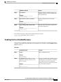
Inheriting a Port Profile
You can inherit a port profile onto an existing port profile. The switch supports four levels of inheritance.
Procedure
Step 1
Command or Action
Purpose
configure terminal
Enters configuration mode.
Example:
switch# configure terminal
switch(config)#
Step 2
port-profile name
Enters port profile configuration mode for the
specified port profile.
Example:
switch(config)# port-profile test
switch(config-port-prof)#
Step 3
inherit port-profile name
Inherits another port profile onto the existing
one. The original port profile assumes all the
configurations of the inherited port profile.
Example:
switch(config-port-prof)#
port-profile adam
switch(config-port-prof)#
Step 4
inherit
exit
Exits the port profile configuration mode.
Example:
switch(config-port-prof)# exit
switch(config)#
Step 5
show port-profile
(Optional)
Displays the port profile configuration.
Example:
switch(config)# show port-profile name
Step 6
copy running-config startup-config
Example:
(Optional)
Copies the running configuration to the
startup configuration.
switch(config)# copy running-config
startup-config
This example shows how to inherit the port profile named adam onto the port profile named test:
switch# configure terminal
switch(config)# port-profile test
switch(config-ppm)# inherit port-profile adam
switch(config-ppm)#
Cisco Nexus 5000 Series NX-OS Interfaces Configuration Guide, Release 5.2(1)N1(1)
22
78-26881-OL
Configuring Layer 2 Interfaces
Port Profiles
This example shows how to add the interface commands to a port profile named ppEth configured for Ethernet
interfaces:
switch# configure terminal
switch(config)# port-profile ppEth
switch(config-port-prof)# switchport mode trunk
switch(config-port-prof)# switchport trunk allowed vlan 300-400
switch(config-port-prof)# flowcontrol receive on
switch(config-port-prof)# speed 10000
switch(config-port-prof)#
This example shows how to inherit a port profile named ppEth configured for Ethernet interfaces into an
existing port profile named test:
switch# configure terminal
switch(config)# port-profile test
switch(config-port-prof)# inherit port-profile ppEth
switch(config-port-prof)#
This example shows how to assign a port profile named ppEth configured for Ethernet interfaces to a range
of Ethernet interfaces:
switch# configure terminal
switch(config)# interface ethernet 1/2-5
switch(config-if)# inherit port-profile ppEth
switch(config-if)#
This example shows how to remove an inherited port profile named ppEth from an existing port profile named
test:
switch# configure terminal
switch(config)# port-profile test
switch(config-port-prof)# no inherit port-profile ppEth
switch(config-port-prof)#
Removing an Inherited Port Profile
You can remove an inherited port profile.
Procedure
Step 1
Command or Action
Purpose
configure terminal
Enters configuration mode.
Example:
switch# configure terminal
switch(config)#
Step 2
port-profile name
Enters port profile configuration mode for
the specified port profile.
Example:
switch(config)# port-profile test
switch(config-port-prof)#
Step 3
no inherit port-profile name
Removes an inherited port profile from
this port profile.
Example:
switch(config-port-prof)#
port-profile adam
switch(config-port-prof)#
no inherit
Cisco Nexus 5000 Series NX-OS Interfaces Configuration Guide, Release 5.2(1)N1(1)
78-26881-OL
23
Configuring Layer 2 Interfaces
Port Profiles
Step 4
Command or Action
Purpose
exit
Exits the port profile configuration mode.
Example:
switch(config-port-prof)# exit
switch(config)#
Step 5
show port-profile
(Optional)
Displays the port profile configuration.
Example:
switch(config)# show port-profile name
Step 6
copy running-config startup-config
Example:
(Optional)
Copies the running configuration to the
startup configuration.
switch(config)# copy running-config
startup-config
This example shows how to remove the inherited port profile named adam from the port profile named test:
switch# configure terminal
switch(config)# port-profile test
switch(config-ppm)# no inherit port-profile adam
switch(config-ppm)#
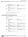
Assigning a Port Profile to a Range of Interfaces
You can assign a port profile to an interface or to a range of interfaces. All of the interfaces must be the same
type.
Procedure
Step 1
Command or Action
Purpose
configure terminal
Enters configuration mode.
Example:
switch# configure terminal
switch(config)#
Step 2
interface [ethernet slot/port | interface-vlan vlan-id Selects the range of interfaces.
| port-channel number]
Example:
switch(config)# interface ethernet 7/3-5,
10/2, 11/20-25
switch(config-if)#
Step 3
inherit port-profile name
Assigns the specified port profile to the
selected interfaces.
Example:
switch(config-if)# inherit port-profile adam
switch(config-if)#
Cisco Nexus 5000 Series NX-OS Interfaces Configuration Guide, Release 5.2(1)N1(1)
24
78-26881-OL
Configuring Layer 2 Interfaces
Port Profiles
Step 4
Command or Action
Purpose
exit
Exits port profile configuration mode.
Example:
switch(config-port-prof)# exit
switch(config)#
Step 5
show port-profile
(Optional)
Displays the port profile configuration.
Example:
switch(config)# show port-profile name
Step 6
copy running-config startup-config
Example:
(Optional)
Copies the running configuration to the
startup configuration.
switch(config)# copy running-config
startup-config
This example shows how to assign the port profile named adam to Ethernet interfaces 2/3 to 2/5, 3/2, and
1/20 to 1/25:
switch# configure terminal
switch(config)# interface ethernet 2/3 to 2/5, 3/2, and 1/20 to 1/25
switch(config-if)# inherit port-profile adam
switch(config-if)#
Removing a Port Profile from a Range of Interfaces
You can remove a port profile from some or all of the interfaces to which you have applied the profile.
Procedure
Step 1
Command or Action
Purpose
configure terminal
Enters configuration mode.
Example:
switch# configure terminal
switch(config)#
Step 2
interface [ethernet slot/port | interface-vlan vlan-id Selects the range of interfaces.
| port-channel number]
Example:
switch(config)# interface ethernet 7/3-5,
10/2, 11/20-25
switch(config-if)#
Step 3
no inherit port-profile name
Removes the specified port profile from
the selected interfaces.
Example:
switch(config-if)# no inherit port-profile
adam
switch(config-if)#
Cisco Nexus 5000 Series NX-OS Interfaces Configuration Guide, Release 5.2(1)N1(1)
78-26881-OL
25
Configuring Layer 2 Interfaces
Port Profiles
Step 4
Command or Action
Purpose
exit
Exits port profile configuration mode.
Example:
switch(config-port-prof)# exit
switch(config)#
Step 5
show port-profile
(Optional)
Displays the port profile configuration.
Example:
switch(config)# show port-profile name
Step 6
copy running-config startup-config
Example:
(Optional)
Copies the running configuration to the
startup configuration.
switch(config)# copy running-config
startup-config
This example shows how tos remove the port profile named adam from Ethernet interfaces 1/3-5:
switch# configure terminal
switch(config)# interface ethernet 1/3-5
switch(config-if)# no inherit port-profile adam
switch(config-if)#
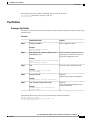
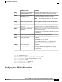
Configuration Examples for Port Profiles
The following example shows how to configure a port profile, inherit the port profile on an Ethernet interface,
and enabling the port profile.
switch(config)#
switch(config)# show running-config interface Ethernet1/14
!Command: show running-config interface Ethernet1/14
!Time: Thu Aug 26 07:01:32 2010
version 5.0(2)N1(1)
interface Ethernet1/14
switch(config)# port-profile type ethernet alpha
switch(config-port-prof)# switchport mode trunk
switch(config-port-prof)# switchport trunk allowed vlan 10-15
switch(config-port-prof)#
switch(config-port-prof)# show running-config port-profile alpha
!Command: show running-config port-profile alpha
!Time: Thu Aug 26 07:02:29 2010
version 5.0(2)N1(1)
port-profile type ethernet alpha
switchport mode trunk
switchport trunk allowed vlan 10-15
switch(config-port-prof)# int eth 1/14
switch(config-if)# inherit port-profile alpha
switch(config-if)#
switch(config-if)# port-profile type ethernet alpha
switch(config-port-prof)# state enabled
switch(config-port-prof)#
Cisco Nexus 5000 Series NX-OS Interfaces Configuration Guide, Release 5.2(1)N1(1)
26
78-26881-OL
Configuring Layer 2 Interfaces
Configuring the Debounce Timer
switch(config-port-prof)# sh running-config interface ethernet 1/14
!Command: show running-config interface Ethernet1/14
!Time: Thu Aug 26 07:03:17 2010
version 5.0(2)N1(1)
interface Ethernet1/14
inherit port-profile alpha
switch(config-port-prof)# sh running-config interface ethernet 1/14 expand-port-profile
!Command: show running-config interface Ethernet1/14 expand-port-profile
!Time: Thu Aug 26 07:03:21 2010
version 5.0(2)N1(1)
interface Ethernet1/14
switchport mode trunk
switchport trunk allowed vlan 10-15
switch(config-port-prof)#
Configuring the Debounce Timer
You can enable the debounce timer for Ethernet ports by specifying a debounce time (in milliseconds) or
disable the timer by specifying a debounce time of 0.
You can show the debounce times for all of the Ethernet ports by using the show interface debounce command.
To enable or disable the debounce timer, perform this task:
Procedure
Command or Action
Purpose
Step 1
switch# configure terminal
Enters configuration mode.
Step 2
switch(config)# interface type slot/port Enters interface configuration mode for the specified
interface.
Step 3
switch(config-if)# link debounce time Enables the debounce timer for the amount of time
(1 to 5000 milliseconds) specified.
milliseconds
Disables the debounce timer if you specify 0
milliseconds.
This example shows how to enable the debounce timer and set the debounce time to 1000 milliseconds for
an Ethernet interface:
switch# configure terminal
switch(config)# interface ethernet 1/4
switch(config-if)# link debounce time 1000
This example shows how to disable the debounce timer for an Ethernet interface:
switch# configure terminal
switch(config)# interface ethernet 1/4
switch(config-if)# link debounce time 0
Cisco Nexus 5000 Series NX-OS Interfaces Configuration Guide, Release 5.2(1)N1(1)
78-26881-OL
27
Configuring Layer 2 Interfaces
Configuring the Description Parameter
Configuring the Description Parameter
You can provide textual interface descriptions for the Ethernet ports.
Procedure
Command or Action
Purpose
Step 1
switch# configure terminal
Enters configuration mode.
Step 2
switch(config)# interface type slot/port
Enters interface configuration mode for the
specified interface.
Step 3
switch(config-if)# description test
Specifies the description for the interface.
This example shows how to set the interface description to Server 3 Interface:
switch# configure terminal
switch(config)# interface ethernet 1/3
switch(config-if)# description Server 3 Interface
Disabling and Restarting Ethernet Interfaces
You can shut down and restart an Ethernet interface. This action disables all of the interface functions and
marks the interface as being down on all monitoring displays. This information is communicated to other
network servers through all dynamic routing protocols. When shut down, the interface is not included in any
routing updates.
Procedure
Command or Action
Purpose
Step 1
switch# configure terminal
Enters configuration mode.
Step 2
switch(config)# interface type slot/port
Enters interface configuration mode for the
specified interface.
Step 3
switch(config-if)# shutdown
Disables the interface.
Step 4
switch(config-if)# no shutdown
Restarts the interface.
This example shows how to disable an Ethernet port:
switch# configure terminal
switch(config)# interface ethernet 1/4
switch(config-if)# shutdown
Cisco Nexus 5000 Series NX-OS Interfaces Configuration Guide, Release 5.2(1)N1(1)
28
78-26881-OL
Configuring Layer 2 Interfaces
Displaying Interface Information
This example shows how to restart an Ethernet interface:
switch# configure terminal
switch(config)# interface ethernet 1/4
switch(config-if)# no shutdown
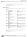
Displaying Interface Information
To view configuration information about the defined interfaces, perform one of these tasks:
Command
Purpose
switch# show interface type slot/port
Displays the detailed configuration of the specified
interface.
switch# show interface type slot/port capabilities
Displays detailed information about the capabilities
of the specified interface. This option is only available
for physical interfaces
switch# show interface type slot/port transceiver
Displays detailed information about the transceiver
connected to the specified interface. This option is
only available for physical interfaces.
switch# show interface brief
Displays the status of all interfaces.
switch# show interface debounce
Displays the debounce status of all interfaces.
switch# show interface flowcontrol
Displays the detailed listing of the flow control
settings on all interfaces.
show port--profile
Displays information about the port profiles.
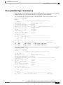
The show interface command is invoked from EXEC mode and displays the interface configurations. Without
any arguments, this command displays the information for all the configured interfaces in the switch.
This example shows how to display the physical Ethernet interface:
switch# show interface ethernet 1/1
Ethernet1/1 is up
Hardware is 1000/10000 Ethernet, address is 000d.eca3.5f08 (bia 000d.eca3.5f08)
MTU 1500 bytes, BW 10000000 Kbit, DLY 10 usec,
reliability 255/255, txload 190/255, rxload 192/255
Encapsulation ARPA
Port mode is trunk
full-duplex, 10 Gb/s, media type is 1/10g
Input flow-control is off, output flow-control is off
Auto-mdix is turned on
Rate mode is dedicated
Switchport monitor is off
Last clearing of "show interface" counters never
5 minute input rate 942201806 bytes/sec, 14721892 packets/sec
5 minute output rate 935840313 bytes/sec, 14622492 packets/sec
Rx
129141483840 input packets 0 unicast packets 129141483847 multicast packets
0 broadcast packets 0 jumbo packets 0 storm suppression packets
8265054965824 bytes
0 No buffer 0 runt 0 Overrun
Cisco Nexus 5000 Series NX-OS Interfaces Configuration Guide, Release 5.2(1)N1(1)
78-26881-OL
29
Configuring Layer 2 Interfaces
Displaying Interface Information
0 crc 0 Ignored 0 Bad etype drop
0 Bad proto drop
Tx
119038487241 output packets 119038487245 multicast packets
0 broadcast packets 0 jumbo packets
7618463256471 bytes
0 output CRC 0 ecc
0 underrun 0 if down drop
0 output error 0 collision 0 deferred
0 late collision 0 lost carrier 0 no carrier
0 babble
0 Rx pause 8031547972 Tx pause 0 reset
This example shows how to display the physical Ethernet capabilities:
switch# show interface ethernet 1/1 capabilities
Ethernet1/1
Model:
734510033
Type:
10Gbase-(unknown)
Speed:
1000,10000
Duplex:
full
Trunk encap. type:
802.1Q
Channel:
yes
Broadcast suppression: percentage(0-100)
Flowcontrol:
rx-(off/on),tx-(off/on)
Rate mode:
none
QOS scheduling:
rx-(6q1t),tx-(1p6q0t)
CoS rewrite:
no
ToS rewrite:
no
SPAN:
yes
UDLD:
yes
Link Debounce:
yes
Link Debounce Time:
yes
MDIX:
no
FEX Fabric:
yes
This example shows how to display the physical Ethernet transceiver:
switch# show interface ethernet 1/1 transceiver
Ethernet1/1
sfp is present
name is CISCO-EXCELIGHT
part number is SPP5101SR-C1
revision is A
serial number is ECL120901AV
nominal bitrate is 10300 MBits/sec
Link length supported for 50/125mm fiber is 82 m(s)
Link length supported for 62.5/125mm fiber is 26 m(s)
cisco id is -cisco extended id number is 4
This example shows how to display a brief interface status (some of the output has been removed for brevity):
switch# show interface brief
-------------------------------------------------------------------------------Ethernet
VLAN
Type Mode
Status Reason
Speed
Port
Interface
Ch #
-------------------------------------------------------------------------------Eth1/1
200
eth trunk up
none
10G(D) -Eth1/2
1
eth trunk up
none
10G(D) -Eth1/3
300
eth access down
SFP not inserted
10G(D) -Eth1/4
300
eth access down
SFP not inserted
10G(D) -Eth1/5
300
eth access down
Link not connected
1000(D) -Eth1/6
20
eth access down
Link not connected
10G(D) -Eth1/7
300
eth access down
SFP not inserted
10G(D) -...
This example shows how to display the link debounce status (some of the output has been removed for brevity):
switch# show interface debounce
-------------------------------------------------------------------------------Port
Debounce time
Value(ms)
-------------------------------------------------------------------------------...
Eth1/1
enable
100
Eth1/2
enable
100
Cisco Nexus 5000 Series NX-OS Interfaces Configuration Guide, Release 5.2(1)N1(1)
30
78-26881-OL
Configuring Layer 2 Interfaces
Default Physical Ethernet Settings
Eth1/3
...
enable
100
This example shows how to display the CDP neighbors:
Note
The default device ID field for CDP advertisement is the hostname and serial number, as in the example
above.
switch# show cdp neighbors
Capability Codes: R - Router, T - Trans-Bridge, B - Source-Route-Bridge
S - Switch, H - Host, I - IGMP, r - Repeater,
V - VoIP-Phone, D - Remotely-Managed-Device,
s - Supports-STP-Dispute
Device ID
Local Intrfce
Hldtme Capability Platform
d13-dist-1
mgmt0
148
S I
WS-C2960-24TC
n5k(FLC12080012)
Eth1/5
8
S I s
N5K-C5020P-BA
Port ID
Fas0/9
Eth1/5
Default Physical Ethernet Settings
The following table lists the default settings for all physical Ethernet interfaces:
Parameter
Default Setting
Debounce
Enable, 100 milliseconds
Duplex
Auto (full-duplex)
Encapsulation
ARPA
MTU1
1500 bytes
Port Mode
Access
Speed
Auto (10000)
1 MTU cannot be changed per-physical Ethernet interface. You modify MTU by selecting maps of QoS classes.
Cisco Nexus 5000 Series NX-OS Interfaces Configuration Guide, Release 5.2(1)N1(1)
78-26881-OL
31
Configuring Layer 2 Interfaces
Default Physical Ethernet Settings
Cisco Nexus 5000 Series NX-OS Interfaces Configuration Guide, Release 5.2(1)N1(1)
32
78-26881-OL
CHAPTER
3
Configuring Layer 3 Interfaces
This chapter contains the following sections:
• Information About Layer 3 Interfaces, page 33
• Licensing Requirements for Layer 3 Interfaces, page 36
• Guidelines and Limitations for Layer 3 Interfaces, page 36
• Default Settings for Layer 3 Interfaces, page 36
• Configuring Layer 3 Interfaces, page 36
• Verifying the Layer 3 Interfaces Configuration, page 41
• Monitoring Layer 3 Interfaces, page 42
• Configuration Examples for Layer 3 Interfaces, page 43
• Related Documents for Layer 3 Interfaces, page 44
• MIBs for Layer 3 Interfaces, page 44
• Standards for Layer 3 Interfaces, page 44
Information About Layer 3 Interfaces
Layer 3 interfaces forward packets to another device using static or dynamic routing protocols. You can use
Layer 3 interfaces for IP routing and inter-VLAN routing of Layer 2 traffic.
Routed Interfaces
You can configure a port as a Layer 2 interface or a Layer 3 interface. A routed interface is a physical port
that can route IP traffic to another device. A routed interface is a Layer 3 interface only and does not support
Layer 2 protocols, such as the Spanning Tree Protocol (STP).
All Ethernet ports are switched interfaces by default. You can change this default behavior with the CLI setup
script or through the system default switchport command.
Cisco Nexus 5000 Series NX-OS Interfaces Configuration Guide, Release 5.2(1)N1(1)
78-26881-OL
33
Configuring Layer 3 Interfaces
Subinterfaces
You can assign an IP address to the port, enable routing, and assign routing protocol characteristics to this
routed interface.
You can assign a static MAC address to a Layer 3 interface. For information on configuring MAC addresses,
see the Layer 2 Switching Configuration Guide for your device.
You can also create a Layer 3 port channel from routed interfaces.
Routed interfaces and subinterfaces support exponentially decayed rate counters. Cisco NX-OS tracks the
following statistics with these averaging counters:
• Input packets/sec
• Output packets/sec
• Input bytes/sec
• Output bytes/sec
Subinterfaces
You can create virtual subinterfaces on a parent interface configured as a Layer 3 interface. A parent interface
can be a physical port or a port channel.
Subinterfaces divide the parent interface into two or more virtual interfaces on which you can assign unique
Layer 3 parameters such as IP addresses and dynamic routing protocols. The IP address for each subinterface
should be in a different subnet from any other subinterface on the parent interface.
You create a subinterface with a name that consists of the parent interface name (for example, Ethernet 2/1)
followed by a period and then by a number that is unique for that subinterface. For example, you could create
a subinterface for Ethernet interface 2/1 named Ethernet 2/1.1 where .1 indicates the subinterface.
Cisco NX-OS enables subinterfaces when the parent interface is enabled. You can shut down a subinterface
independent of shutting down the parent interface. If you shut down the parent interface, Cisco NX-OS shuts
down all associated subinterfaces as well.
One use of subinterfaces is to provide unique Layer 3 interfaces to each VLAN that is supported by the parent
interface. In this scenario, the parent interface connects to a Layer 2 trunking port on another device. You
configure a subinterface and associate the subinterface to a VLAN ID using 802.1Q trunking.
The following figure shows a trunking port from a switch that connects to router B on interface E 2/1. This
interface contains three subinterfaces that are associated with each of the three VLANs that are carried by the
trunking port.
Figure 2: Subinterfaces for VLANs
Cisco Nexus 5000 Series NX-OS Interfaces Configuration Guide, Release 5.2(1)N1(1)
34
78-26881-OL
Configuring Layer 3 Interfaces
VLAN Interfaces
VLAN Interfaces
A VLAN interface or a switch virtual interface (SVI) is a virtual routed interface that connects a VLAN on
the device to the Layer 3 router engine on the same device. Only one VLAN interface can be associated with
a VLAN, but you need to configure a VLAN interface for a VLAN only when you want to route between
VLANs or to provide IP host connectivity to the device through a virtual routing and forwarding (VRF)
instance that is not the management VRF. When you enable VLAN interface creation, Cisco NX-OS creates
a VLAN interface for the default VLAN (VLAN 1) to permit remote switch administration.
You must enable the VLAN network interface feature before you can configure it. The system automatically
takes a checkpoint prior to disabling the feature, and you can roll back to this checkpoint. For information
about rollbacks and checkpoints, see the System Management Configuration Guide for your device.
Note
You cannot delete the VLAN interface for VLAN 1.
You can route across VLAN interfaces to provide Layer 3 inter-VLAN routing by configuring a VLAN
interface for each VLAN that you want to route traffic to and assigning an IP address on the VLAN interface.
For more information on IP addresses and IP routing, see the Unicast Routing Configuration Guide for your
device.
The following figure shows two hosts connected to two VLANs on a device. You can configure VLAN
interfaces for each VLAN that allows Host 1 to communicate with Host 2 using IP routing between the VLANs.
VLAN 1 communicates at Layer 3 over VLAN interface 1and VLAN 10 communicates at Layer 3 over VLAN
interface 10.
Figure 3: Connecting Two VLANs with VLAN Interfaces
Loopback Interfaces
A loopback interface is a virtual interface with a single endpoint that is always up. Any packet that is transmitted
over a loopback interface is immediately received by this interface. Loopback interfaces emulate a physical
interface.
Cisco Nexus 5000 Series NX-OS Interfaces Configuration Guide, Release 5.2(1)N1(1)
78-26881-OL
35
Configuring Layer 3 Interfaces
Tunnel Interfaces
You can use loopback interfaces for performance analysis, testing, and local communications. Loopback
interfaces can act as a termination address for routing protocol sessions. This loopback configuration allows
routing protocol sessions to stay up even if some of the outbound interfaces are down.
Tunnel Interfaces
Cisco NX-OS supports tunnel interfaces as IP tunnels. IP tunnels can encapsulate a same- ayer or higher layer
protocol and transport the result over IP through a tunnel that is created between two routers.
Licensing Requirements for Layer 3 Interfaces
This feature does not require a license. Any feature not included in a license package is bundled with the Cisco
NX-OS system images and is provided at no extra charge to you. For a complete explanation of the Cisco
NX-OS licensing scheme, see the Cisco NX-OS Licensing Guide.
Guidelines and Limitations for Layer 3 Interfaces
Layer 3 interfaces have the following configuration guidelines and limitations:
• If you change a Layer 3 interface to a Layer 2 interface, Cisco NX-OS shuts down the interface, reenables
the interface, and removes all configuration specific to Layer 3.
• If you change a Layer 2 interface to a Layer 3 interface, Cisco NX-OS shuts down the interface, reenables
the interface, and deletes all configuration specific to Layer 2.
Default Settings for Layer 3 Interfaces
The default setting for the Layer 3 Admin state is Shut.
Configuring Layer 3 Interfaces
Configuring a Routed Interface
Procedure
Command or Action
Purpose
Step 1
switch# configure terminal
Enters global configuration mode.
Step 2
switch(config)# interface ethernet Enters interface configuration mode.
slot/port
Step 3
switch(conifg-if)# no switchport Configures the interface as a Layer 3 interface and deletes
any configuration specific to Layer 2 on this interface.
Cisco Nexus 5000 Series NX-OS Interfaces Configuration Guide, Release 5.2(1)N1(1)
36
78-26881-OL
Configuring Layer 3 Interfaces
Configuring a Subinterface
Command or Action
Purpose
Note
To convert a Layer 3 interface back into a Layer
2 interface, use the switchport command.
Step 4
switch(config-if)# [ip | ipv6
]ip-address/length
Configures an IP address for this interface.
Step 5
switch(config-if)# medium
{broadcast | p2p}
(Optional)
Configures the interface medium as either point to point
or broadcast.
Note
The default setting is broadcast, and this setting
does not appear in any of the show commands.
However, if you do change the setting to p2p, you
will see this setting when you enter the show
running-config command.
Step 6
switch(config-if)# show interfaces (Optional)
Displays the Layer 3 interface statistics.
Step 7
switch(config-if)# copy
running-config startup-config
(Optional)
Saves the change persistently through reboots and restarts
by copying the running configuration to the startup
configuration.
This example shows how to configure an IPv4 routed Layer 3 interface:
switch# configure terminal
switch(config)# interface ethernet 2/1
switch(config-if)# no switchport
switch(config-if)# ip address 192.0.2.1/8
switch(config-if)# copy running-config startup-config
Configuring a Subinterface
Before You Begin
• Configure the parent interface as a routed interface.
• Create the port-channel interface if you want to create a subinterface on that port channel.
Procedure
Command or Action
Step 1
Purpose
switch(config-if)# copy running-config (Optional)
Saves the change persistently through reboots and
startup-config
restarts by copying the running configuration to the
startup configuration.
Cisco Nexus 5000 Series NX-OS Interfaces Configuration Guide, Release 5.2(1)N1(1)
78-26881-OL
37
Configuring Layer 3 Interfaces
Configuring the Bandwidth on an Interface
Command or Action
Purpose
Step 2
switch(config)# interface ethernet
slot/port.number
Enters interface configuration mode. The range for the
slot is from 1 to 255. The range for the port is from 1
to 128.
Step 3
switch(config-if)# [ip | ipv6] address Configures IP address for this interface.
ip-address/length
Step 4
switch(config-if)# encapsulation
dot1Q vlan-id
Configures IEEE 802.1Q VLAN encapsulation on the
subinterface. The range for the vlan-id is from 2 to
4093.
Step 5
switch(config-if)# show interfaces
(Optional)
Displays the Layer 3 interface statistics.
Step 6
switch(config-if)# copy running-config (Optional)
Saves the change persistently through reboots and
startup-config
restarts by copying the running configuration to the
startup configuration.
This example shows how to create a subinterface:
switch# configure terminal
switch(config)# interface ethernet 2/1
switch(config-if)# ip address 192.0.2.1/8
switch(config-if)# encapsulation dot1Q 33
switch(config-if)# copy running-config startup-config
Configuring the Bandwidth on an Interface
You can configure the bandwidth for a routed interface, port channel, or subinterface.
Procedure
Command or Action
Purpose
Step 1
switch# configure terminal
Enters global configuration mode.
Step 2
switch(config)# interface
ethernet slot/port
Enters interface configuration mode. The range for the slot is
from 1 to 255. The range for the port is from 1 to 128.
Step 3
switch(conifg-if)# bandwidth
[value | inherit [value]]
Configures the bandwidth parameter for a routed interface,
port channel, or subinterface, as follows:
• value—Size of the bandwidth in kilobytes. The range is
from 1 to 10000000.
• inherit—Indicates that all subinterfaces of this interface
inherit either the bandwidth value (if a value is specified)
or the bandwidth of the parent interface (if a value is not
specified).
Cisco Nexus 5000 Series NX-OS Interfaces Configuration Guide, Release 5.2(1)N1(1)
38
78-26881-OL
Configuring Layer 3 Interfaces
Configuring a VLAN Interface
Command or Action
Step 4
Purpose
switch(config-if)# copy
(Optional)
running-config startup-config Saves the change persistently through reboots and restarts by
copying the running configuration to the startup configuration.
This example shows how to configure Ethernet interface 2/1 with a bandwidth value of 80000:
switch# configure terminal
switch(config)# interface ethernet 2/1
switch(config-if)# bandwidth 80000
switch(config-if)# copy running-config startup-config
Configuring a VLAN Interface
Procedure
Command or Action
Purpose
Step 1
switch# configure terminal
Enters global configuration mode.
Step 2
switch(config)# feature interface-vlan
Enables VLAN interface mode.
Step 3
switch(config)# interface vlan number
Creates a VLAN interface. The number range is
from 1 to 4094.
Step 4
switch(config-if)# [ip | ipv6 ] address
ip-address/length
Configures an IP address for this interface.
Step 5
switch(config-if)# show interface vlan
number
(Optional)
Displays the VLAN interface statistics. The
number range is from 1 to 4094.
Step 6
switch(config-if)# copy running-config (Optional)
Saves the change persistently through reboots and
startup-config
restarts by copying the running configuration to
the startup configuration.
This example shows how to create a VLAN interface:
switch# configure terminal
switch(config)# feature interface-vlan
switch(config)# interface vlan 10
switch(config-if)# ip address 192.0.2.1/8
switch(config-if)# copy running-config startup-config
Cisco Nexus 5000 Series NX-OS Interfaces Configuration Guide, Release 5.2(1)N1(1)
78-26881-OL
39
Configuring Layer 3 Interfaces
Configuring a Loopback Interface
Configuring a Loopback Interface
Before You Begin
Ensure that the IP address of the loopback interface is unique across all routers on the network.
Procedure
Command or Action
Purpose
Step 1
switch# configure terminal
Enters global configuration mode.
Step 2
switch(config)# interface loopback
instance
Creates a loopback interface. The instance range is
from 0 to 1023.
Step 3
switch(config-if)# [ip | ipv6 ] address
ip-address/length
Configures an IP address for this interface.
Step 4
switch(config-if)# show interface
loopback instance
(Optional)
Displays the loopback interface statistics. The
instance range is from 0 to 1023.
Step 5
switch(config-if)# copy running-config (Optional)
Saves the change persistently through reboots and
startup-config
restarts by copying the running configuration to the
startup configuration.
This example shows how to create a loopback interface:
switch# configure terminal
switch(config)# interface loopback 0
switch(config-if)# ip address 192.0.2.100/8
switch(config-if)# copy running-config startup-config
Assigning an Interface to a VRF
Before You Begin
Assign the IP address for a tunnel interface after you have configured the interface for a VRF.
Procedure
Command or Action
Purpose
Step 1
switch# configure terminal
Enters global configuration mode.
Step 2
switch(config)# interface
interface-typenumber
Enters interface configuration mode.
Cisco Nexus 5000 Series NX-OS Interfaces Configuration Guide, Release 5.2(1)N1(1)
40
78-26881-OL
Configuring Layer 3 Interfaces
Verifying the Layer 3 Interfaces Configuration
Command or Action
Purpose
Step 3
switch(conifg-if)#vrf member vrf-name
Adds this interface to a VRF.
Step 4
switch(config-if)# [ip |
ipv6]ip-address/length
Configures an IP address for this interface. You
must do this step after you assign this interface
to a VRF.
Step 5
switch(config-if)# show vrf [vrf-name]
interface interface-type number
(Optional)
Displays VRF information.
Step 6
switch(config-if)# show interfaces
(Optional)
Displays the Layer 3 interface statistics.
Step 7
switch(config-if)# copy running-config
startup-config
(Optional)
Saves the change persistently through reboots
and restarts by copying the running configuration
to the startup configuration.
This example shows how to add a Layer 3 interface to the VRF:
switch# configure terminal
switch(config)# interface loopback 0
switch(config-if)# vrf member RemoteOfficeVRF
switch(config-if)# ip address 209.0.2.1/16
switch(config-if)# copy running-config startup-config
Verifying the Layer 3 Interfaces Configuration
Use one of the following commands to verify the configuration:
Command
Purpose
show interface ethernet slot/port
Displays the Layer 3 interface configuration, status,
and counters (including the 5-minute exponentially
decayed moving average of inbound and outbound
packet and byte rates).
show interface ethernet slot/port brief
Displays the Layer 3 interface operational status.
show interface ethernet slot/port capabilities
Displays the Layer 3 interface capabilities, including
port type, speed, and duplex.
show interface ethernet slot/port description
Displays the Layer 3 interface description.
show interface ethernet slot/port status
Displays the Layer 3 interface administrative status,
port mode, speed, and duplex.
Cisco Nexus 5000 Series NX-OS Interfaces Configuration Guide, Release 5.2(1)N1(1)
78-26881-OL
41
Configuring Layer 3 Interfaces
Monitoring Layer 3 Interfaces
Command
Purpose
show interface ethernet slot/port.number
Displays the subinterface configuration, status, and
counters (including the f-minute exponentially
decayed moving average of inbound and outbound
packet and byte rates).
show interface port-channel channel-id.number
Displays the port-channel subinterface configuration,
status, and counters (including the 5-minute
exponentially decayed moving average of inbound
and outbound packet and byte rates).
show interface loopback number
Displays the loopback interface configuration, status,
and counters.
show interface loopback number brief
Displays the loopback interface operational status.
show interface loopback number description
Displays the loopback interface description.
show interface loopback number status
Displays the loopback interface administrative status
and protocol status.
show interface vlan number
Displays the VLAN interface configuration, status,
and counters.
show interface vlan number brief
Displays the VLAN interface operational status.
show interface vlan number description
Displays the VLAN interface description.
show interface vlan number private-vlan mapping Displays the VLAN interface private VLAN
information.
show interface vlan number status
Displays the VLAN interface administrative status
and protocol status.
Monitoring Layer 3 Interfaces
Use one of the following commands to display statistics about the feature:
Command
Purpose
show interface ethernet slot/port counters
Displays the Layer 3 interface statistics (unicast,
multicast, and broadcast).
show interface ethernet slot/port counters brief
Displays the Layer 3 interface input and output
counters.
Cisco Nexus 5000 Series NX-OS Interfaces Configuration Guide, Release 5.2(1)N1(1)
42
78-26881-OL
Configuring Layer 3 Interfaces
Configuration Examples for Layer 3 Interfaces
Command
Purpose
show interface ethernet slot/port counters detailed
[all]
Displays the Layer 3 interface statistics. You can
optionally include all 32-bit and 64-bit packet and
byte counters (including errors).
show interface ethernet slot/port counters error
Displays the Layer 3 interface input and output
errors.
show interface ethernet slot/port counters snmp
Displays the Layer 3 interface counters reported
by SNMP MIBs. You cannot clear these counters.
show interface ethernet slot/port.number counters
Displays the subinterface statistics (unicast,
multicast, and broadcast).
show interface port-channel channel-id.number
counters
Displays the port-channel subinterface statistics
(unicast, multicast, and broadcast).
show interface loopback number counters
Displays the loopback interface input and output
counters (unicast, multicast, and broadcast).
show interface loopback number counters detailed
[all]
Displays the loopback interface statistics. You can
optionally include all 32-bit and 64-bit packet and
byte counters (including errors).
show interface loopback number counters errors
Displays the loopback interface input and output
errors.
show interface vlan number counters
Displays the VLAN interface input and output
counters (unicast, multicast, and broadcast).
show interface vlan number counters detailed [all]
Displays the VLAN interface statistics. You can
optionally include all Layer 3 packet and byte
counters (unicast and multicast).
show interface vlan counters snmp
Displays the VLAN interface counters reported
by SNMP MIBs. You cannot clear these counters.
Configuration Examples for Layer 3 Interfaces
This example shows how to configure Ethernet subinterfaces:
switch# configuration terminal
switch(config)# interface ethernet 2/1.10
switch(config-if)# no switchport
switch(config-if)# description Layer 3 for VLAN 10
switch(config-if)# encapsulation dot1q 10
switch(config-if)# ip address 192.0.2.1/8
switch(config-if)# copy running-config startup-config
Cisco Nexus 5000 Series NX-OS Interfaces Configuration Guide, Release 5.2(1)N1(1)
78-26881-OL
43
Configuring Layer 3 Interfaces
Related Documents for Layer 3 Interfaces
This example shows how to configure a VLAN interface:
switch# configuration terminal
switch(config)# interface vlan 100
switch(config-if)# no switchport
switch(config-if)# ipv6 address 33:0DB::2/8
switch(config-if)# copy running-config startup-config
This example shows how to configure a loopback interface:
switch# configuration terminal
switch(config)# interface loopback 3
switch(config-if)# no switchport
switch(config-if)# ip address 192.0.2.2/32
switch(config-if)# copy running-config startup-config
Related Documents for Layer 3 Interfaces
Related Topics
Document Title
Command syntax
For details about command syntax, see the command
reference for your device.
IP
“Configuring IP” chapter in the Unicast Routing
Configuration Guide for your device.
VLAN
“Configuring VLANs” chapter in the Layer 2
Switching Configuration Guide for your device.
MIBs for Layer 3 Interfaces
MIB
MIB Link
IF-MIB
To locate and download MIBs, go to the following
URL:
CISCO-IF-EXTENSION-MIB
http://www.cisco.com/public/sw-center/netmgmt/
cmtk/mibs.shtml
ETHERLIKE-MIB
Standards for Layer 3 Interfaces
No new or modified standards are supported by this feature, and support for existing standards has not been
modified by this feature.
Cisco Nexus 5000 Series NX-OS Interfaces Configuration Guide, Release 5.2(1)N1(1)
44
78-26881-OL
CHAPTER
4
Configuring Port Channels
This chapter contains the following sections:
• Information About Port Channels, page 45
• Configuring Port Channels, page 54
• Verifying Port Channel Configuration, page 63
• Verifying the Load-Balancing Outgoing Port ID , page 64
Information About Port Channels
A port channel bundles individual interfaces into a group to provide increased bandwidth and redundancy.
Port channeling also load balances traffic across these physical interfaces. The port channel stays operational
as long as at least one physical interface within the port channel is operational.
You create an port channel by bundling compatible interfaces. You can configure and run either static port
channels or port channels running the Link Aggregation Control Protocol (LACP).
Any configuration changes that you apply to the port channel are applied to each member interface of that
port channel. For example, if you configure Spanning Tree Protocol (STP) parameters on the port channel,
Cisco NX-OS applies those parameters to each interface in the port channel.
You can use static port channels, with no associated protocol, for a simplified configuration. For more efficient
use of the port channel, you can use the Link Aggregation Control Protocol (LACP), which is defined in IEEE
802.3ad. When you use LACP, the link passes protocol packets.
Related Topics
LACP Overview, on page 51
Understanding Port Channels
Using port channels, Cisco NX-OS provides wider bandwidth, redundancy, and load balancing across the
channels.
You can collect ports into a static port channel or you can enable the Link Aggregation Control Protocol
(LACP). Configuring port channels with LACP requires slightly different steps than configuring static port
Cisco Nexus 5000 Series NX-OS Interfaces Configuration Guide, Release 5.2(1)N1(1)
78-26881-OL
45
Configuring Port Channels
Guidelines and Limitations for Port Channel Configuration
channels. For information on port channel configuration limits, see the Verified Scalability document for your
platform. For more information about load balancing, see Load Balancing Using Port Channels, on page 48.
Note
Cisco NX-OS does not support Port Aggregation Protocol (PAgP) for port channels.
A port channel bundles individual links into a channel group to create a single logical link that provides the
aggregate bandwidth of several physical links. If a member port within a port channel fails, traffic previously
carried over the failed link switches to the remaining member ports within the port channel.
Each port can be in only one port channel. All the ports in an port channel must be compatible; they must use
the same speed and operate in full-duplex mode. When you are running static port channels, without LACP,
the individual links are all in the on channel mode; you cannot change this mode without enabling LACP.
Note
You cannot change the mode from ON to Active or from ON to Passive.
You can create a port channel directly by creating the port-channel interface, or you can create a channel
group that acts to aggregate individual ports into a bundle. When you associate an interface with a channel
group, Cisco NX-OS creates a matching port channel automatically if the port channel does not already exist.
You can also create the port channel first. In this instance, Cisco NX-OS creates an empty channel group with
the same channel number as the port channel and takes the default configuration.
Note
A port channel is operationally up when at least one of the member ports is up and that port’s status is
channeling. The port channel is operationally down when all member ports are operationally down.
Guidelines and Limitations for Port Channel Configuration
Port channels can be configured in one of two ways: either in global configuration mode or in switch profile
mode. Consider the following guidelines and limitations when configuring port channels via the configuration
synchronization feature in Cisco NX-OS:
• Once a port channel is configured using switch profile mode, it cannot be configured using global
configuration (config terminal) mode.
Note
Several port channel sub-commands are not configurable in switch profile mode. These
commands can be configured from global configuration mode even if the port channel
is created and configured in switch profile mode.
For example, the following command can only be configured in global configuration
mode:
switchport private-vlan association trunk primary-vlan secondary-vlan
• Shutdown and no shutdown can be configured in either global configuration mode or switch profile
mode.
Cisco Nexus 5000 Series NX-OS Interfaces Configuration Guide, Release 5.2(1)N1(1)
46
78-26881-OL
Configuring Port Channels
Compatibility Requirements
• If a port channel is created in global configuration mode, channel groups including member interfaces
must also be created using global configuration mode.
• Port channels that are configured within switch profile mode may have members both inside and outside
of a switch profile.
• If you want to import a member interface to a switch profile, the port channel that corresponds with the
member interface must also be present within the switch profile.
For more information on switch profiles, see the .
Compatibility Requirements
When you add an interface to a port channel group, Cisco NX-OS checks certain interface attributes to ensure
that the interface is compatible with the channel group. Cisco NX-OS also checks a number of operational
attributes for an interface before allowing that interface to participate in the port-channel aggregation.
The compatibility check includes the following operational attributes:
• Port mode
• Access VLAN
• Trunk native VLAN
• Allowed VLAN list
• Speed
• 802.3x flow control setting
• MTU
The Cisco Nexus device only supports system level MTU. This attribute cannot be changed on an
individual port basis.
• Broadcast/Unicast/Multicast Storm Control setting
• Priority-Flow-Control
• Untagged CoS
Use the show port-channel compatibility-parameters command to see the full list of compatibility checks
that Cisco NX-OS uses.
You can only add interfaces configured with the channel mode set to on to static port channels. You can also
only add interfaces configured with the channel mode as active or passive to port channels that are running
LACP. You can configure these attributes on an individual member port.
When the interface joins a port channel, the following individual parameters are replaced with the values on
the port channel:
• Bandwidth
• MAC address
• Spanning Tree Protocol
The following interface parameters remain unaffected when the interface joins a port channel:
Cisco Nexus 5000 Series NX-OS Interfaces Configuration Guide, Release 5.2(1)N1(1)
78-26881-OL
47
Configuring Port Channels
Load Balancing Using Port Channels
• Description
• CDP
• LACP port priority
• Debounce
After you enable forcing a port to be added to a channel group by entering the channel-group force command,
the following two conditions occur:
• When an interface joins a port channel the following parameters are removed and they are operationally
replaced with the values on the port channel; however, this change will not be reflected in the
running-configuration for the interface:
• QoS
• Bandwidth
• Delay
• STP
• Service policy
• ACLs
• When an interface joins or leaves a port channel, the following parameters remain unaffected:
• Beacon
• Description
• CDP
• LACP port priority
• Debounce
• UDLD
• Shutdown
• SNMP traps
Load Balancing Using Port Channels
Cisco NX-OS load balances traffic across all operational interfaces in a port channel by reducing part of the
binary pattern formed from the addresses in the frame to a numerical value that selects one of the links in the
channel. Port channels provide load balancing by default.
The basic configuration uses the following criteria to select the link:
• For a Layer 2 frame, it uses the source and destination MAC addresses.
• For a Layer 3 frame, it uses the source and destination MAC addresses and the source and destination
IP addresses.
Cisco Nexus 5000 Series NX-OS Interfaces Configuration Guide, Release 5.2(1)N1(1)
48
78-26881-OL
Configuring Port Channels
Load Balancing Using Port Channels
• For a Layer 4 frame, it uses the source and destination MAC addresses and the source and destination
IP addresses.
Note
You have the option to include the source and destination port number for the Layer 4
frame.
You can configure the switch to use one of the following methods (see the following table for more details)
to load balance across the port channel:
• Destination MAC address
• Source MAC address
• Source and destination MAC address
• Destination IP address
• Source IP address
• Source and destination IP address
• Destination TCP/UDP port number
• Source TCP/UDP port number
• Source and destination TCP/UDP port number
Table 4: Port Channel Load-Balancing Criteria
Configuration
Layer 2 Criteria
Layer 3 Criteria
Layer 4 Criteria
Destination MAC
Destination MAC
Destination MAC
Destination MAC
Source MAC
Source MAC
Source MAC
Source MAC
Source and destination
MAC
Source and destination
MAC
Source and destination
MAC
Source and destination
MAC
Destination IP
Destination MAC
Destination MAC,
destination IP
Destination MAC,
destination IP
Source IP
Source MAC
Source MAC, source IP
Source MAC, source IP
Source and destination IP Source and destination
MAC
Source and destination
MAC, source and
destination IP
Source and destination
MAC, source and
destination IP
Destination TCP/UDP
port
Destination MAC
Destination MAC,
destination IP
Destination MAC,
destination IP, destination
port
Source TCP/UDP port
Source MAC
Source MAC, source IP
Source MAC, source IP,
source port
Cisco Nexus 5000 Series NX-OS Interfaces Configuration Guide, Release 5.2(1)N1(1)
78-26881-OL
49
Configuring Port Channels
Load Balancing Using Port Channels
Configuration
Layer 2 Criteria
Layer 3 Criteria
Layer 4 Criteria
Source and destination
TCP/UDP port
Source and destination
MAC
Source and destination
MAC, source and
destination IP
Source and destination
MAC, source and
destination IP, source and
destination port
Fabric Extenders are not configurable individually. Fabric extender configurations are defined on the Cisco
Nexus device. In the case of the port-channel load balancing protocol, the table below illustrates which
port-channel load balancing option is automatically configured on the fabric extender modules as a result of
the configuration performed on the Cisco Nexus device.
The following table shows the criteria used for each configuration:
Table 5: Port channel Load-Balancing Criteria for the Cisco Nexus 2232 and Cisco Nexus 2248 Fabric Extenders
Configuration
Layer 2 Criteria
Layer 3 Criteria
Layer 4 Criteria
Destination MAC
Source and destination
MAC
Source and destination
MAC
Source and destination
MAC
Source MAC
Source and destination
MAC
Source and destination
MAC
Source and destination
MAC
Source and destination
MAC
Source and destination
MAC
Source and destination
MAC
Source and destination
MAC
Destination IP
Source and destination
MAC
Source and destination
MAC, and source and
destination IP
Source and destination
MAC, and source and
destination IP
Source IP
Source and destination
MAC
Source and destination
MAC, and source and
destination IP
Source and destination
MAC, and source and
destination IP
Source and destination IP Source and destination
MAC
Source and destination
MAC, and source and
destination IP
Source and destination
MAC, and source and
destination IP
Destination TCP/UDP
port
Source and destination
MAC
Source and destination
MAC, and source and
destination IP
Source and destination
MAC, source and
destination IP , and source
and destination port
Source TCP/UDP port
Source and destination
MAC
Source and destination
MAC, and source and
destination IP
Source and destination
MAC, source and
destination IP , and source
and destination port
Cisco Nexus 5000 Series NX-OS Interfaces Configuration Guide, Release 5.2(1)N1(1)
50
78-26881-OL
Configuring Port Channels
Understanding LACP
Configuration
Layer 2 Criteria
Layer 3 Criteria
Layer 4 Criteria
Source and destination
TCP/UDP port
Source and destination
MAC
Source and destination
MAC, source and
destination IP
Source and destination
MAC, source and
destination IP , and source
and destination port
Use the option that provides the balance criteria with the greatest variety in your configuration. For example,
if the traffic on a port channel is going only to a single MAC address and you use the destination MAC address
as the basis of port-channel load balancing, the port channel always chooses the same link in that port channel;
using source addresses or IP addresses might result in better load balancing.
Understanding LACP
LACP Overview
Note
You must enable the LACP feature before you can configure and use LACP functions.
The following figure shows how individual links can be combined into LACP port channels and channel
groups as well as function as individual links.
Figure 4: Individual Links Combined into a Port channel
With LACP, just like with static port-channels, you can bundle up to 16 interfaces in a channel group.
Note
When you delete the port channel, Cisco NX-OS automatically deletes the associated channel group. All
member interfaces revert to their previous configuration.
You cannot disable LACP while any LACP configurations are present.
Cisco Nexus 5000 Series NX-OS Interfaces Configuration Guide, Release 5.2(1)N1(1)
78-26881-OL
51
Configuring Port Channels
Understanding LACP
LACP ID Parameters
LACP uses the following parameters:
• LACP system priority—Each system that runs LACP has an LACP system priority value. You can
accept the default value of 32768 for this parameter, or you can configure a value between 1 and 65535.
LACP uses the system priority with the MAC address to form the system ID and also uses the system
priority during negotiation with other devices. A higher system priority value means a lower priority.
Note
The LACP system ID is the combination of the LACP system priority value and the MAC address.
• LACP port priority—Each port configured to use LACP has an LACP port priority. You can accept the
default value of 32768 for the LACP port priority, or you can configure a value between 1 and 65535.
LACP uses the port priority with the port number to form the port identifier. LACP uses the port priority
to decide which ports should be put in standby mode when there is a limitation that prevents all compatible
ports from aggregating and which ports should be put into active mode. A higher port priority value
means a lower priority for LACP. You can configure the port priority so that specified ports have a lower
priority for LACP and are most likely to be chosen as active links, rather than hot-standby links.
• LACP administrative key—LACP automatically configures an administrative key value equal to the
channel-group number on each port configured to use LACP. The administrative key defines the ability
of a port to aggregate with other ports. A port’s ability to aggregate with other ports is determined by
these factors:
◦ Port physical characteristics, such as the data rate, the duplex capability, and the point-to-point or
shared medium state
◦ Configuration restrictions that you establish
Channel Modes
Individual interfaces in port channels are configured with channel modes. When you run static port channels,
with no protocol, the channel mode is always set to on. After you enable LACP globally on the device, you
enable LACP for each channel by setting the channel mode for each interface to active or passive. You can
configure either channel mode for individual links in the LACP channel group.
Note
You must enable LACP globally before you can configure an interface in either the active or passive
channel mode.
The following table describes the channel modes.
Cisco Nexus 5000 Series NX-OS Interfaces Configuration Guide, Release 5.2(1)N1(1)
52
78-26881-OL
Configuring Port Channels
Understanding LACP
Table 6: Channel Modes for Individual Links in a Port channel
Channel Mode
Description
passive
LACP mode that places a port into a passive
negotiating state, in which the port responds to LACP
packets that it receives but does not initiate LACP
negotiation.
active
LACP mode that places a port into an active
negotiating state, in which the port initiates
negotiations with other ports by sending LACP
packets.
on
All static port channels, that is, that are not running
LACP, remain in this mode. If you attempt to change
the channel mode to active or passive before enabling
LACP, the device returns an error message.
You enable LACP on each channel by configuring
the interface in that channel for the channel mode as
either active or passive. When an LACP attempts to
negotiate with an interface in the on state, it does not
receive any LACP packets and becomes an individual
link with that interface; it does not join the LACP
channel group.
Both the passive and active modes allow LACP to negotiate between ports to determine if they can form a
port channel, based on criteria such as the port speed and the trunking state. The passive mode is useful when
you do not know whether the remote system, or partner, supports LACP.
Ports can form an LACP port channel when they are in different LACP modes as long as the modes are
compatible as in the following examples:
• A port in active mode can form a port channel successfully with another port that is in active mode.
• A port in active mode can form a port channel with another port in passive mode.
• A port in passive mode cannot form a port channel with another port that is also in passive mode because
neither port will initiate negotiation.
• A port in on mode is not running LACP.
LACP Marker Responders
Using port channels, data traffic may be dynamically redistributed due to either a link failure or load balancing.
LACP uses the Marker Protocol to ensure that frames are not duplicated or reordered because of this
redistribution. Cisco NX-OS supports only Marker Responders.
Cisco Nexus 5000 Series NX-OS Interfaces Configuration Guide, Release 5.2(1)N1(1)
78-26881-OL
53
Configuring Port Channels
Configuring Port Channels
LACP-Enabled and Static Port Channel Differences
The following table provides a brief summary of major differences between port channels with LACP enabled
and static port channels. For information about the maximum configuration limits, see the Verified Scalability
document for your device.
Table 7: Port channels with LACP Enabled and Static Port channels
Configurations
Port Channels with LACP Enabled Static Port Channels
Protocol applied
Enable globally.
Not applicable.
Channel mode of links
Can be either:
Can only be On.
• Active
• Passive
Configuring Port Channels
Creating a Port Channel
You can create a port channel before creating a channel group. Cisco NX-OS automatically creates the
associated channel group.
Note
If you want LACP-based port channels, you need to enable LACP.
Procedure
Command or Action
Purpose
Step 1
switch# configure terminal
Enters configuration mode.
Step 2
switch(config)# interface port-channel Specifies the port-channel interface to configure, and
enters the interface configuration mode. The range is
channel-number
from 1 to 4096. Cisco NX-OS automatically creates
the channel group if it does not already exist.
Step 3
switch(config)# no interface
port-channel channel-number
Removes the port channel and deletes the associated
channel group.
This example shows how to create a port channel:
switch# configure terminal
switch (config)# interface port-channel 1
Cisco Nexus 5000 Series NX-OS Interfaces Configuration Guide, Release 5.2(1)N1(1)
54
78-26881-OL
Configuring Port Channels
Adding a Port to a Port Channel
Adding a Port to a Port Channel
You can add a port to a new channel group or to a channel group that already contains ports. Cisco NX-OS
creates the port channel associated with this channel group if the port channel does not already exist.
Note
If you want LACP-based port channels, you need to enable LACP.
Procedure
Command or Action
Purpose
Step 1
switch# configure terminal
Enters configuration mode.
Step 2
switch(config)# interface type
slot/port
Specifies the interface that you want to add to a channel
group and enters the interface configuration mode.
Step 3
switch(config-if)# switchport mode (Optional)
Configures the interface as a trunk port.
trunk
Step 4
switch(config-if)# switchport trunk (Optional)
{allowed vlan vlan-id | native vlan Configures necessary parameters for a trunk port.
vlan-id}
Step 5
switch(config-if)# channel-group
channel-number
Step 6
switch(config-if)# no channel-group (Optional)
Removes the port from the channel group. The port
reverts to its original configuration.
Configures the port in a channel group and sets the
mode. The channel-number range is from 1 to 4096.
Cisco NX-OS creates the port channel associated with
this channel group if the port channel does not already
exist. This is called implicit port channel creation.
This example shows how to add an Ethernet interface 1/4 to channel group 1:
switch# configure terminal
switch (config)# interface ethernet 1/4
switch(config-if)# switchport mode trunk
switch(config-if)# channel-group 1
Configuring Load Balancing Using Port Channels
You can configure the load-balancing algorithm for port channels that applies to the entire device.
Note
If you want LACP-based port channels, you need to enable LACP.
Cisco Nexus 5000 Series NX-OS Interfaces Configuration Guide, Release 5.2(1)N1(1)
78-26881-OL
55
Configuring Port Channels
Configuring Load Balancing Using Port Channels
Procedure
Command or Action
Purpose
Step 1
switch# configure terminal
Enters configuration mode.
Step 2
switch(config)# port-channel
load-balance ethernet
{[destination-ip | destination-mac |
destination-port | source-dest-ip |
source-dest-mac | source-dest-port |
source-ip | source-mac | source-port]
crc-poly}
Specifies the load-balancing algorithm for the device. The
range depends on the device. The default is
source-dest-mac.
Beginning with Cisco NX-OS Release 5.0(3)N2(1), the
Cisco Nexus 5500 Platform switches support 8 hash
polynomials that can be used for compression on the
hash-parameters. Depending on variations in the hash
parameters for egress traffic flows from a port channel,
different polynomials could provide different load
distribution results. The default hash polynomial is CRC8a.
The variable can be configured as follows:
• CRC8a
• CRC8b
• CRC8c
• CRC8d
• CRC8e
• CRC8f
• CRC8g
Step 3
switch(config)# no port-channel
load-balance ethernet
(Optional)
Restores the default load-balancing algorithm of
source-dest-mac.
Step 4
switch# show port-channel
load-balance
(Optional)
Displays the port-channel load-balancing algorithm.
This example shows how to configure source IP load balancing for port channels:
switch# configure terminal
switch (config)# port-channel load-balance ethernet source-ip
Note
Before Release 4.0(1a)N1 of Cisco NX-OS, the source-dest-ip, source-dest-mac, and source-dest-port
keywords were source-destination-ip, source-destination-mac, and source-destination-port, respectively.
Cisco Nexus 5000 Series NX-OS Interfaces Configuration Guide, Release 5.2(1)N1(1)
56
78-26881-OL
Configuring Port Channels
Configuring Hardware Hashing for Multicast Traffic
Configuring Hardware Hashing for Multicast Traffic
By default, ingress multicast traffic on any port in the switch selects a particular port channel member to
egress the traffic. You can configure hardware hashing for multicast traffic to reduce potential bandwidth
issues and to provide effective load balancing of the ingress multicast traffic. Use the hardware multicast
hw-hash command to enable hardware hashing. To restore the default, use the no hardware multicast
hw-hash command.
Procedure
Command or Action
Purpose
Step 1
switch# configure terminal
Enters configuration mode.
Step 2
switch(config)# interface port-channel
channel-number
Selects the port channel and enters the interface
configuration mode.
Step 3
switch(config-if)# hardware multicast
hw-hash
Configures hardware hashing for the specified
port channel.
This example shows how to configure hardware hashing on a port channel:
switch# configure terminal
switch (config)# interface port-channel 21
switch(config-if)# hardware multicast hw-hash
This example shows how to remove hardware hashing from a port channel:
switch# configure terminal
switch (config)# interface port-channel 21
switch(config-if)# no hardware multicast hw-hash
Enabling LACP
LACP is disabled by default; you must enable LACP before you begin LACP configuration. You cannot
disable LACP while any LACP configuration is present.
LACP learns the capabilities of LAN port groups dynamically and informs the other LAN ports. Once LACP
identifies correctly matched Ethernet links, it facilitates grouping the links into an port channel. The port
channel is then added to the spanning tree as a single bridge port.
Procedure
Command or Action
Purpose
Step 1
switch# configure terminal
Enters configuration mode.
Step 2
switch(config)# feature lacp
Enables LACP on the switch.
Step 3
switch(config)# show feature
(Optional)
Displays enabled features.
Cisco Nexus 5000 Series NX-OS Interfaces Configuration Guide, Release 5.2(1)N1(1)
78-26881-OL
57
Configuring Port Channels
Configuring the Channel Mode for a Port
This example shows how to enable LACP:
switch# configure terminal
switch(config)# feature lacp
Configuring the Channel Mode for a Port
You can configure the channel mode for each individual link in the LACP port channel as active or passive.
This channel configuration mode allows the link to operate with LACP.
When you configure port channels with no associated protocol, all interfaces on both sides of the link remain
in the on channel mode.
Before You Begin
Ensure that you have enabled the LACP feature.
Procedure
Command or Action
Purpose
Step 1
switch# configure terminal Enters configuration mode.
Step 2
switch(config)# interface type Specifies the interface to configure, and enters the interface
configuration mode.
slot/port
Step 3
switch(config-if)#
channel-group
channel-number [force]
[mode {on | active | passive}]
Specifies the port mode for the link in a port channel. After LACP
is enabled, you configure each link or the entire channel as active
or passive.
force—Specifies that the LAN port be forcefully added to the
channel group. This option is available in Cisco NX-OS Release
5.0(2)N2(1).
mode—Specifies the port channel mode of the interface.
active—Specifies that when you enable LACP, this command
enables LACP on the specified interface. The interface is in an active
negotiating state in which the port initiates negotiations with other
ports by sending LACP packets.
on—(Default mode) Specifies that all port channels that are not
running LACP remain in this mode.
passive—Enables LACP only if an LACP device is detected. The
interface is in a passive negotiation state in which the port responds
to LACP packets that it receives but does not initiate LACP
negotiation.
When you run port channels with no associated protocol, the channel
mode is always on.
Step 4
switch(config-if)# no
Returns the port mode to on for the specified interface.
channel-group number mode
Cisco Nexus 5000 Series NX-OS Interfaces Configuration Guide, Release 5.2(1)N1(1)
58
78-26881-OL
Configuring Port Channels
Configuring the LACP Fast Timer Rate
This example shows how to set the LACP-enabled interface to active port-channel mode for Ethernet interface
1/4 in channel group 5:
switch# configure terminal
switch (config)# interface ethernet 1/4
switch(config-if)# channel-group 5 mode active
This example shows how to forcefully add an interface to the channel group 5:
switch(config)# interface ethernet 1/1
switch(config-if)# channel-group 5 force
switch(config-if)#
Configuring the LACP Fast Timer Rate
You can change the LACP timer rate to modify the duration of the LACP timeout. Use the lacp rate command
to set the rate at which LACP control packets are sent to an LACP-supported interface. You can change the
timeout rate from the default rate (30 seconds) to the fast rate (1 second). This command is supported only
on LACP-enabled interfaces.
Before You Begin
Ensure that you have enabled the LACP feature.
Procedure
Command or Action
Purpose
Step 1
switch# configure terminal
Enters configuration mode.
Step 2
switch(config)# interface type slot/port Specifies the interface to configure and enters the
interface configuration mode.
Step 3
switch(config-if)# lacp rate fast
Configures the fast rate (one second) at which LACP
control packets are sent to an LACP-supported
interface.
This example shows how to configure the LACP fast rate on Ethernet interface 1/4:
switch# configure terminal
switch (config)# interface ethernet 1/4
switch(config-if)# lacp rate fast
This example shows how to restore the LACP default rate (30 seconds) on Ethernet interface 1/4.
switch# configure terminal
switch (config)# interface ethernet 1/4
switch(config-if)# no lacp rate fast
Cisco Nexus 5000 Series NX-OS Interfaces Configuration Guide, Release 5.2(1)N1(1)
78-26881-OL
59
Configuring Port Channels
Configuring the LACP System Priority and System ID
Configuring the LACP System Priority and System ID
The LACP system ID is the combination of the LACP system priority value and the MAC address.
Before You Begin
Ensure that you have enabled the LACP feature.
Procedure
Command or Action
Purpose
Step 1
switch# configure terminal
Enters configuration mode.
Step 2
switch(config)# lacp system-priority Configures the system priority for use with LACP.
Valid values are 1 through 65535, and higher numbers
priority
have lower priority. The default value is 32768.
Step 3
switch# show lacp system-identifier (Optional)
Displays the LACP system identifier.
This example shows how to set the LACP system priority to 2500:
switch# configure terminal
switch(config)# lacp system-priority 2500
Configuring the LACP Port Priority
You can configure each link in the LACP port channel for the port priority.
Before You Begin
Ensure that you have enabled the LACP feature.
Procedure
Command or Action
Purpose
Step 1
switch# configure terminal
Enters configuration mode.
Step 2
switch(config)# interface type
slot/port
Specifies the interface to configure, and enters the
interface configuration mode.
Step 3
switch(config-if)# lacp port-priority Configures the port priority for use with LACP. Valid
values are 1 through 65535, and higher numbers have
priority
lower priority. The default value is 32768.
Cisco Nexus 5000 Series NX-OS Interfaces Configuration Guide, Release 5.2(1)N1(1)
60
78-26881-OL
Configuring Port Channels
Disabling LACP Graceful Convergence
This example shows how to set the LACP port priority for Ethernet interface 1/4 to 40000:
switch# configure terminal
switch (config)# interface ethernet 1/4
switch(config-if)# lacp port priority 40000
Disabling LACP Graceful Convergence
Before You Begin
• Enable the LACP feature.
• Confirm that the port channel is in the administratively down state.
• Ensure that you are in the correct VDC. To switch to the correct VDC, enter the switchto vdc command.
Procedure
Step 1
Command or Action
Purpose
configure terminal
Enters global configuration mode.
Example:
switch# configure terminal
switch(config)#
Step 2
interface port-channel number
Example:
Specifies the port channel interface to
configure, and enters interface configuration
mode.
switch(config)# interface port-channel
1
switch(config) #
Step 3
Administratively shuts down the port channel.
shutdown
Example:
switch(config-if)# shutdown
switch(config-if) #
Step 4
no lacp graceful-convergence
Disables LACP graceful convergence on the
specified port channel.
Example:
switch(config-if)# no lacp
graceful-convergence
switch(config-if) #
Step 5
no shutdown
Administratively brings the port channel up.
Example:
switch(config-if)# no shutdown
switch(config-if) #
Cisco Nexus 5000 Series NX-OS Interfaces Configuration Guide, Release 5.2(1)N1(1)
78-26881-OL
61
Configuring Port Channels
Reenabling LACP Graceful Convergence
Step 6
Command or Action
Purpose
copy running-config startup-config
(Optional)
Saves the change persistently through reboots
and restarts by copying the running
configuration to the startup configuration.
Example:
switch(config-if)# copy running-config
startup-config
The following example disables LACP graceful convergence on a port channel:
switch# configure terminal
switch(config) # interface port-channel 1
switch(config-if) # shutdown
switch(config-if) # no lacp graceful-convergence
switch(config-if) # no shutdown
switch(config-if) #
Reenabling LACP Graceful Convergence
Before You Begin
• Enable the LACP feature.
• Confirm that the port channel is in the administratively down state.
• Ensure that you are in the correct VDC. To switch to the correct VDC, enter the switchto vdc command.
Procedure
Step 1
Command or Action
Purpose
configure terminal
Enters global configuration mode.
Example:
switch# configure terminal
switch(config)#
Step 2
interface port-channel number
Example:
Specifies the port channel interface to
configure, and enters interface configuration
mode.
switch(config)# interface port-channel
1
switch(config) #
Step 3
shutdown
Administratively shuts down the port channel.
Example:
switch(config-if)# shutdown
switch(config-if) #
Cisco Nexus 5000 Series NX-OS Interfaces Configuration Guide, Release 5.2(1)N1(1)
62
78-26881-OL
Configuring Port Channels
Verifying Port Channel Configuration
Step 4
Command or Action
Purpose
lacp graceful-convergence
Enables LACP graceful convergence on the
specified port channel.
Example:
switch(config-if)# lacp
graceful-convergence
switch(config-if) #
Step 5
Administratively brings the port channel up.
no shutdown
Example:
switch(config-if)# no shutdown
switch(config-if) #
Step 6
copy running-config startup-config
Example:
switch(config-if)# copy running-config
startup-config
(Optional)
Saves the change persistently through reboots
and restarts by copying the running
configuration to the startup configuration.
The following example disables LACP graceful convergence on a port channel:
switch# configure terminal
switch(config) # interface port-channel 1
switch(config-if) # shutdown
switch(config-if) # lacp graceful-convergence
switch(config-if) # no shutdown
switch(config-if) #
Verifying Port Channel Configuration
To display port channel configuration information, perform one of the following tasks:
Command
Purpose
switch# show interface port-channel
channel-number
Displays the status of a port channel interface.
switch# show feature
Displays enabled features.
switch# show resource
Displays the number of resources currently available
in the system.
switch# show lacp {counters | interface type
slot/port | neighbor | port-channel |
system-identifier}
Displays LACP information.
switch# show port-channel
compatibility-parameters
Displays the parameters that must be the same among
the member ports in order to join a port channel.
switch# show port-channel database [interface
port-channel channel-number]
Displays the aggregation state for one or more
port-channel interfaces.
Cisco Nexus 5000 Series NX-OS Interfaces Configuration Guide, Release 5.2(1)N1(1)
78-26881-OL
63
Configuring Port Channels
Verifying the Load-Balancing Outgoing Port ID
Command
Purpose
switch# show port-channel summary
Displays a summary for the port channel interfaces.
switch# show port-channel traffic
Displays the traffic statistics for port channels.
switch# show port-channel usage
Displays the range of used and unused channel
numbers.
switch# show port-channel database
Displays information on current running of the port
channel feature.
switch# show port-channel load-balance
Displays information about load-balancing using port
channels.
Verifying the Load-Balancing Outgoing Port ID
Command Guidelines
The show port-channel load-balance command allows you to verify which ports a given frame is hashed to
on a port channel. You need to specify the VLAN and the destination MAC in order to get accurate results.
Note
Certain traffic flows are not subject to hashing, for example when there is a single port in a port-channel.
To display the load-balancing outgoing port ID, perform one of the tasks listed in the table below.
Command
Purpose
switch# show port-channel load-balance
forwarding-path interface port-channel
port-channel-id vlan vlan-id dst-ip src-ip dst-mac
src-mac l4-src-port port-id l4-dst-port port-id
Displays the outgoing port ID.
Example
This example shows the output of the short port-channel load-balance command.
switch# show port-channel load-balance forwarding-path interface port-channel 10 vlan 1
dst-ip 1.225.225.225 src-ip 1.1.10.10 src-mac aa:bb:cc:dd:ee:ff
l4-src-port 0 l4-dst-port 1
Missing params will be substituted by 0's. Load-balance Algorithm on switch: source-dest-port
crc8_hash:204 Outgoing port id: Ethernet 1/1 Param(s) used to calculate load balance:
dst-port: 0
src-port: 0
dst-ip: 1.225.225.225
src-ip: 1.1.10.10
dst-mac: 0000.0000.0000
src-mac: aabb.ccdd.eeff
Cisco Nexus 5000 Series NX-OS Interfaces Configuration Guide, Release 5.2(1)N1(1)
64
78-26881-OL
CHAPTER
5
Configuring Virtual Port Channels
This chapter contains the following sections:
• Information About vPCs, page 65
• Guidelines and Limitations for vPCs, page 79
• Configuring vPCs, page 80
• Configuring the vPC Peer Switch, page 93
• Verifying the vPC Configuration, page 95
• vPC Example Configurations, page 101
• vPC Default Settings, page 105
Information About vPCs
vPC Overview
A virtual port channel (vPC) allows links that are physically connected to two different Cisco Nexus devices
or Cisco Nexus Fabric Extenders to appear as a single port channel by a third device (see the following figure).
The third device can be a switch, server, or any other networking device. You can configure vPCs in topologies
that include Cisco Nexus devices connected to Cisco Nexus Fabric Extenders. A vPC can provide multipathing,
Cisco Nexus 5000 Series NX-OS Interfaces Configuration Guide, Release 5.2(1)N1(1)
78-26881-OL
65
Configuring Virtual Port Channels
vPC Overview
which allows you to create redundancy by enabling multiple parallel paths between nodes and load balancing
traffic where alternative paths exist.
Figure 5: vPC Architecture
You configure the EtherChannels by using one of the following:
• No protocol
• Link Aggregation Control Protocol (LACP)
When you configure the EtherChannels in a vPC—including the vPC peer link channel—each switch can
have up to 16 active links in a single EtherChannel. When you configure a vPC on a Fabric Extender, only
one port is allowed in an EtherChannel.
Note
You must enable the vPC feature before you can configure or run the vPC functionality.
To enable the vPC functionality, you must create a peer-keepalive link and a peer-link under the vPC domain
for the two vPC peer switches to provide the vPC functionality.
To create a vPC peer link you configure an EtherChannel on one Cisco Nexus device by using two or more
Ethernet ports. On the other switch, you configure another EtherChannel again using two or more Ethernet
ports. Connecting these two EtherChannels together creates a vPC peer link.
Note
We recommend that you configure the vPC peer-link EtherChannels as trunks.
The vPC domain includes both vPC peer devices, the vPC peer-keepalive link, the vPC peer link, and all of
the EtherChannels in the vPC domain connected to the downstream device. You can have only one vPC
domain ID on each vPC peer device.
Note
Always attach all vPC devices using EtherChannels to both vPC peer devices.
Cisco Nexus 5000 Series NX-OS Interfaces Configuration Guide, Release 5.2(1)N1(1)
66
78-26881-OL
Configuring Virtual Port Channels
Terminology
A vPC provides the following benefits:
• Allows a single device to use an EtherChannel across two upstream devices
• Eliminates Spanning Tree Protocol (STP) blocked ports
• Provides a loop-free topology
• Uses all available uplink bandwidth
• Provides fast convergence if either the link or a switch fails
• Provides link-level resiliency
• Assures high availability
Terminology
vPC Terminology
The terminology used in vPCs is as follows:
• vPC—The combined EtherChannel between the vPC peer devices and the downstream device.
• vPC peer device—One of a pair of devices that are connected with the special EtherChannel known as
the vPC peer link.
• vPC peer link—The link used to synchronize states between the vPC peer devices.
• vPC member port—Interfaces that belong to the vPCs.
• Host vPC port—Fabric Extender host interfaces that belong to a vPC.
• vPC domain—This domain includes both vPC peer devices, the vPC peer-keepalive link, and all of the
port channels in the vPC connected to the downstream devices. It is also associated to the configuration
mode that you must use to assign vPC global parameters. The vPC domain ID must be the same on both
switches.
• vPC peer-keepalive link—The peer-keepalive link monitors the vitality of a vPC peer Cisco Nexus
device. The peer-keepalive link sends configurable, periodic keepalive messages between vPC peer
devices.
No data or synchronization traffic moves over the vPC peer-keepalive link; the only traffic on this link
is a message that indicates that the originating switch is operating and running vPCs.
Fabric Extender Terminology
The terminology used for the Cisco Nexus Fabric Extender is as follows:
• Fabric interface—A 10-Gigabit Ethernet uplink port designated for connection from the Fabric Extender
to its parent switch. A fabric interface cannot be used for any other purpose. It must be directly connected
to the parent switch.
• EtherChannel fabric interface—An EtherChannel uplink connection from the Fabric Extender to its
parent switch. This connection consists of fabric interfaces bundled into a single logical channel.
Cisco Nexus 5000 Series NX-OS Interfaces Configuration Guide, Release 5.2(1)N1(1)
78-26881-OL
67
Configuring Virtual Port Channels
Supported vPC Topologies
• Host interface—An Ethernet interface for server or host connectivity. These ports are 1-Gigabit Ethernet
interfaces or 10-Gigabit Ethernet interfaces, depending on the fabric extender model.
• EtherChannel host interface—An EtherChannel downlink connection from the Fabric Extender host
interface to a server port.
Note
An EtherChannel host interface consists of only one host interface and can be configured
either as a Link Aggregation Control Protocol (LACP) or non-LACP EtherChannel.
Supported vPC Topologies
Cisco Nexus 5000 Series Switch vPC Topology
You can connect a pair of Cisco Nexus 5000 Series switches or a pair of Cisco Nexus 5500 Series switches
in a vPC directly to another switch or to a server. vPC peer switches must be of the same type, for example,
you can connect a pair of Nexus 5000 series switches or a pair of Nexus 5500 Series switches but you cannot
connect a Nexus 5000 Series switch to a Nexus 5500 Series switch in a vPC topology. Up to 8 interfaces
could be connected to each Cisco Nexus 5000 Series switch providing 16 interfaces bundled for the vPC pair.
The topology that is shown in the following figure provides the vPC functionality to dual connected switches
or servers with 10-Gigabit or 1-Gigabit Ethernet uplink interfaces.
Figure 6: Switch-to-Switch vPC Topology
Note
The first 8 ports on the Cisco Nexus 5010 switch and the first 16 ports on the Cisco Nexus 5020 switch
are switchable 1-Gigabit and 10-Gigabit ports. You can enable vPC functionality on these ports in 1-Gigabit
mode.
The switch connected to the pair of Cisco Nexus 5000 Series switches can be any standards-based Ethernet
switch. Common environments to use this configuration include Blade Chassis with dual switches connected
to the pair of Cisco Nexus 5000 Series switches through vPC or Unified Computing Systems connected to
the pair of Cisco Nexus 5000 Series switches.
Cisco Nexus 5000 Series NX-OS Interfaces Configuration Guide, Release 5.2(1)N1(1)
68
78-26881-OL
Configuring Virtual Port Channels
Supported vPC Topologies
Single Homed Fabric Extender vPC Topology
You can connect a server with dual or quad or more network adapters that are configured in a vPC to a pair
of Cisco Nexus Fabric Extenders which are connected to the Cisco Nexus devices as depicted. Depending on
the FEX model, you may be able to connect one or more network adapter interfaces to each fabric extender.
As an example, the following figure refers to a topology built with the Cisco Nexus 2148T fabric extender,
where a server has one link only to each fabric extender. A topology with Cisco Nexus 2248TP or with Cisco
Nexus 2232PP fabric extender could consist of more links from the server to a single fabric extender.
. The topology that is shown in the following figure provides the vPC functionality to dual homed servers
with 1-Gigabit Ethernet uplink interfaces.
Figure 7: Single Homed Fabric Extender vPC Topology
The Cisco Nexus device can support up to 12 configured single homed Fabric Extenders (576 ports) with this
topology however only 480 576 dual homed host servers can be configured in a vPCs with this configuration.
Note
The Cisco Nexus 2148T fabric extender does not support EtherChannels on its host interfaces. Therefore
a maximum of two links can be configured in an EtherChannel from the server where each link is connected
to a separate Fabric Extender.
Cisco Nexus 5000 Series NX-OS Interfaces Configuration Guide, Release 5.2(1)N1(1)
78-26881-OL
69
Configuring Virtual Port Channels
vPC Domain
Dual Homed Fabric Extender vPC Topology
You can connect the Cisco Nexus Fabric Extender to two upstream Cisco Nexus devices and downstream to
a number of single homed servers. The topology shown in the following figure provides the vPC functionality
to singly connected servers with 1-Gigabit Ethernet uplink interfaces.
Figure 8: Dual Homed Fabric Extender vPC Topology
The Cisco Nexus device can support up to 12 configured dual homed Fabric Extenders with this topology. A
maximum of 576 single homed servers can be connected to this configuration.
vPC Domain
To create a vPC domain, you must first create a vPC domain ID on each vPC peer switch using a number
from 1 to 1000. This ID must be the same on a set of vPC peer devices.
You can configure the EtherChannels and vPC peer links by using LACP or no protocol. When possible, we
recommend that you use LACP on the peer-link, because LACP provides configuration checks against a
configuration mismatch on the EtherChannel.
The vPC peer switches use the vPC domain ID that you configure to automatically assign a unique vPC system
MAC address. Each vPC domain has a unique MAC address that is used as a unique identifier for the specific
vPC-related operations, although the switches use the vPC system MAC addresses only for link-scope
operations, such as LACP. We recommend that you create each vPC domain within the contiguous network
with a unique domain ID. You can also configure a specific MAC address for the vPC domain, rather than
having the Cisco NX-OS software assign the address.
The vPC peer switches use the vPC domain ID that you configure to automatically assign a unique vPC system
MAC address. The switches use the vPC system MAC addresses only for link-scope operations, such as LACP
or BPDUs. You can also configure a specific MAC address for the vPC domain.
Cisco recommends that you configure the same VPC domain ID on both peers and, the domain ID should be
unique in the network. For example, if there are two different VPCs (one in access and one in aggregation)
then each vPC should have a unique domain ID.
After you create a vPC domain, the Cisco NX-OS software automatically creates a system priority for the
vPC domain. You can also manually configure a specific system priority for the vPC domain.
Cisco Nexus 5000 Series NX-OS Interfaces Configuration Guide, Release 5.2(1)N1(1)
70
78-26881-OL
Configuring Virtual Port Channels
Peer-Keepalive Link and Messages
Note
If you manually configure the system priority, you must ensure that you assign the same priority value on
both vPC peer switches. If the vPC peer switches have different system priority values, the vPC will not
come up.
Peer-Keepalive Link and Messages
The Cisco NX-OS software uses a peer-keepalive link between the vPC peers to transmit periodic, configurable
keepalive messages. You must have Layer 3 connectivity between the peer switches to transmit these messages;
the system cannot bring up the vPC peer link unless a peer-keepalive link is already up and running.
If one of the vPC peer switches fails, the vPC peer switch on the other side of the vPC peer link senses the
failure when it does not receive any peer-keepalive messages. The default interval time for the vPC
peer-keepalive message is 1 second. You can configure the interval between 400 milliseconds and 10 seconds.
You can also configure a timeout value with a range of 3 to 20 seconds; the default timeout value is 5 seconds.
The peer-keepalive status is checked only when the peer-link goes down.
The vPC peer-keepalive can be carried either in the management or default VRF on the Cisco Nexus device.
When you configure the switches to use the management VRF, the source and destination for the keepalive
messages are the mgmt 0 interface IP addresses. When you configure the switches to use the default VRF, an
SVI must be created to act as the source and destination addresses for the vPC peer-keepalive messages.
Ensure that both the source and destination IP addresses used for the peer-keepalive messages are unique in
your network and these IP addresses are reachable from the VRF associated with the vPC peer-keepalive link.
Note
We recommend that you configure the vPC peer-keepalive link on the Cisco Nexus device to run in the
management VRF using the mgmt 0 interfaces. If you configure the default VRF, ensure that the vPC
peer link is not used to carry the vPC peer-keepalive messages.
Compatibility Parameters for vPC Peer Links
Many configuration and operational parameters must be identical on all interfaces in the vPC. After you enable
the vPC feature and configure the peer link on both vPC peer switches, Cisco Fabric Services (CFS) messages
provide a copy of the configuration on the local vPC peer switch configuration to the remote vPC peer switch.
The system then determines whether any of the crucial configuration parameters differ on the two switches.
Enter the show vpc consistency-parameters command to display the configured values on all interfaces in
the vPC. The displayed configurations are only those configurations that would limit the vPC peer link and
vPC from coming up.
The compatibility check process for vPCs differs from the compatibility check for regular EtherChannels.
Configuration Parameters That Must Be Identical
The configuration parameters in this section must be configured identically on both switches at either end of
the vPC peer link.
Cisco Nexus 5000 Series NX-OS Interfaces Configuration Guide, Release 5.2(1)N1(1)
78-26881-OL
71
Configuring Virtual Port Channels
Compatibility Parameters for vPC Peer Links
Note
You must ensure that all interfaces in the vPC have the identical operational and configuration parameters
listed in this section.
Enter the show vpc consistency-parameters command to display the configured values on all interfaces
in the vPC. The displayed configurations are only those configurations that would limit the vPC peer link
and vPC from coming up.
The switch automatically check for compatibility of these parameters on the vPC interfaces. The per-interface
parameters must be consistent per interface, and the global parameters must be consistent globally.
• Port-channel mode: on, off, or active
• Link speed per channel
• Duplex mode per channel
• Trunk mode per channel:
◦ Native VLAN
◦ VLANs allowed on trunk
◦ Tagging of native VLAN traffic
• Spanning Tree Protocol (STP) mode
• STP region configuration for Multiple Spanning Tree (MST)
• Enable or disable state per VLAN
• STP global settings:
◦ Bridge Assurance setting
◦ Port type setting—We recommend that you set all vPC interfaces as normal ports
◦ Loop Guard settings
• STP interface settings:
◦ Port type setting
◦ Loop Guard
◦ Root Guard
• For the Fabric Extender vPC topology, all the interface level parameters mentioned above should be
identically configured for host interface from both the switches.
• Fabric Extender FEX number configured on an EtherChannel fabric interface; for the Fabric Extender
vPC toplogy.
If any of these parameters are not enabled or defined on either switch, the vPC consistency check ignores
those parameters.
Cisco Nexus 5000 Series NX-OS Interfaces Configuration Guide, Release 5.2(1)N1(1)
72
78-26881-OL
Configuring Virtual Port Channels
Graceful Type-1 Check
Note
To ensure that none of the vPC interfaces are in the suspend mode, enter the show vpc brief and show
vpc consistency-parameters commands and check the syslog messages.
Configuration Parameters That Should Be Identical
When any of the following parameters are not configured identically on both vPC peer switches, a
misconfiguration may cause undesirable behavior in the traffic flow:
• MAC aging timers
• Static MAC entries
• VLAN interface—Each switch on the end of the vPC peer link must have a VLAN interface configured
for the same VLAN on both ends and they must be in the same administrative and operational mode.
Those VLANs configured on only one switch of the peer link do not pass traffic using the vPC or peer
link. You must create all VLANs on both the primary and secondary vPC switches, or the VLAN will
be suspended.
• Private VLAN configuration
• All ACL configurations and parameters
• Quality of service (QoS) configuration and parameters—Local parameters; global parameters must be
identical
• STP interface settings:
◦ BPDU Filter
◦ BPDU Guard
◦ Cost
◦ Link type
◦ Priority
◦ VLANs (Rapid PVST+)
To ensure that all the configuration parameters are compatible, we recommend that you display the
configurations for each vPC peer switch once you configure the vPC.
Graceful Type-1 Check
Beginning with Cisco NX--OS Release 5.0(2)N2(1), when a consistency check fails, vPCs are brought down
only on the secondary vPC switch. The VLANs remain up on the primary switch and Type-1 configurations
can be performed without traffic disruption. This feature is used both in the case of global as well as
interface-specific Type-1 inconsistencies.
This feature is not enabled for dual-active FEX ports. When a Type-1 mismatch occurs, VLANs are suspended
on these ports on both switches.
Cisco Nexus 5000 Series NX-OS Interfaces Configuration Guide, Release 5.2(1)N1(1)
78-26881-OL
73
Configuring Virtual Port Channels
Per-VLAN Consistency Check
Per-VLAN Consistency Check
Beginning with Cisco NX-OS Release 5.0(2)N2(1), some Type-1 consistency checks are performed on a
per-VLAN basis when spanning tree is enabled or disabled on a VLAN. VLANs that do not pass the consistency
check are brought down on both the primary and secondary switches while other VLANs are not affected.
vPC Auto-Recovery
Beginning with Cisco NX-OS Release 5.0(2)N2(1), the vPC auto-recovery feature re-enables vPC links in
the following scenarios:
When both vPC peer switches reload and only one switch reboots, auto-recovery allows that switch to assume
the role of the primary switch and the vPC links will be allowed to come up after a predetermined period of
time. The reload delay period in this scenario can range from 240-3600 seconds.
When vPCs are disabled on a secondary vPC switch due to a peer-link failure and then the primary vPC switch
fails or is unable to forward traffic, the secondary switch re-enables the vPCs. In this scenario, the vPC waits
for three consecutive keep-alive failures to recover the vPC links.
The vPC auto-recovery feature is disabled by default.
vPC Peer Links
A vPC peer link is the link that is used to synchronize the states between the vPC peer devices.
Note
You must configure the peer-keepalive link before you configure the vPC peer link or the peer link will
not come up.
vPC Peer Link Overview
You can have only two switches as vPC peers; each switch can serve as a vPC peer to only one other vPC
peer. The vPC peer switches can also have non-vPC links to other switches.
To make a valid configuration, you configure an EtherChannel on each switch and then configure the vPC
domain. You assign the EtherChannel on each switch as a peer link. For redundancy, we recommend that you
should configure at least two dedicated ports into the EtherChannel; if one of the interfaces in the vPC peer
link fails, the switch automatically falls back to use another interface in the peer link.
Note
We recommend that you configure the EtherChannels in trunk mode.
Many operational parameters and configuration parameters must be the same in each switch connected by a
vPC peer link. Because each switch is completely independent on the management plane, you must ensure
that the switches are compatible on the critical parameters. vPC peer switches have separate control planes.
After configuring the vPC peer link, you should display the configuration on each vPC peer switch to ensure
that the configurations are compatible.
Cisco Nexus 5000 Series NX-OS Interfaces Configuration Guide, Release 5.2(1)N1(1)
74
78-26881-OL
Configuring Virtual Port Channels
vPC Number
Note
You must ensure that the two switches connected by the vPC peer link have certain identical operational
and configuration parameters.
When you configure the vPC peer link, the vPC peer switches negotiate that one of the connected switches
is the primary switch and the other connected switch is the secondary switch. By default, the Cisco NX-OS
software uses the lowest MAC address to elect the primary switch. The software takes different actions on
each switch—that is, the primary and secondary—only in certain failover conditions. If the primary switch
fails, the secondary switch becomes the operational primary switch when the system recovers, and the previously
primary switch is now the secondary switch.
You can also configure which of the vPC switches is the primary switch. If you want to configure the role
priority again to make one vPC switch the primary switch, configure the role priority on both the primary and
secondary vPC switches with the appropriate values, shut down the EtherChannel that is the vPC peer link
on both switches by entering the shutdown command, and reenable the EtherChannel on both switches by
entering the no shutdown command.
MAC addresses that are learned over vPC links are also synchronized between the peers.
Configuration information flows across the vPC peer links using the Cisco Fabric Services over Ethernet
(CFSoE) protocol. All MAC addresses for those VLANs configured on both switches are synchronized
between vPC peer switches. The software uses CFSoE for this synchronization.
If the vPC peer link fails, the software checks the status of the remote vPC peer switch using the peer-keepalive
link, which is a link between vPC peer switches, to ensure that both switches are up. If the vPC peer switch
is up, the secondary vPC switch disables all vPC ports on its switch. The data then forwards down the remaining
active links of the EtherChannel.
The software learns of a vPC peer switch failure when the keepalive messages are not returned over the
peer-keepalive link.
Use a separate link (vPC peer-keepalive link) to send configurable keepalive messages between the vPC peer
switches. The keepalive messages on the vPC peer-keepalive link determines whether a failure is on the vPC
peer link only or on the vPC peer switch. The keepalive messages are used only when all the links in the peer
link fail.
vPC Number
Once you have created the vPC domain ID and the vPC peer link, you can create EtherChannels to attach the
downstream switch to each vPC peer switch. That is, you create one single EtherChannel on the downstream
switch with half of the ports to the primary vPC peer switch and the other half of the ports to the secondary
peer switch.
On each vPC peer switch, you assign the same vPC number to the EtherChannel that connects to the downstream
switch. You will experience minimal traffic disruption when you are creating vPCs. To simplify the
configuration, you can assign the vPC ID number for each EtherChannel to be the same as the EtherChannel
itself (that is, vPC ID 10 for EtherChannel 10).
Note
The vPC number that you assign to the EtherChannel connecting to the downstream switch from the vPC
peer switch must be identical on both vPC peer switches.
Cisco Nexus 5000 Series NX-OS Interfaces Configuration Guide, Release 5.2(1)N1(1)
78-26881-OL
75
Configuring Virtual Port Channels
vPC Interactions with Other Features
vPC Interactions with Other Features
Configuring vPC Peer Links and Links to the Core
Configure the command line interface by using a track object and a track list that is associated with the Layer
3 link to the core and on all vPC peer links on both vPC peer devices. You use this configuration to avoid
dropping traffic if that particular module goes down because when all the tracked objects on the track list go
down, the system does the following:
• Stops the vPC primary peer device sending peer-keepalive messages which forces the vPC secondary
peer device to take over.
• Brings down all the downstream vPCs on that vPC peer device, which forces all the traffic to be rerouted
in the access switch toward the other vPC peer device.
Once you configure this feature and if the module fails, the system automatically suspends all the vPC links
on the primary vPC peer device and stops the peer-keepalive messages. This action forces the vPC secondary
device to take over the primary role and all the vPC traffic to go to this new vPC primary device until the
system stabilizes.
Create a track list that contains all the links to the core and all the vPC peer links as its object. Enable tracking
for the specified vPC domain for this track list. Apply this same configuration to the other vPC peer device.
Before You Begin
To configure a track list to switch over vPC to the remote peer when all related interfaces fail:
Procedure
Command or Action
Purpose
Step 1
switch# configure terminal
Enters global configuration mode.
Step 2
switch(config)# interface type slot/port
Enters interface configuration mode.
Step 3
switch(config-if)# track track-id interface Configures the track objects on an interface
(Layer 3 to core).
type slot/port line-protocol
Step 4
switch(config-track)# track track-id
interface type slot/port line-protocol
Step 5
switch(config)# track track-id interface Configures the track objects on a port channel
(vPC peer link).
port-channel port line-protocol
Step 6
switch(config)# track track-id list boolean Creates a track list that contains all the interfaces
in the track list using the Boolean OR to trigger
[OR | AND]
when all the objects fail. or trigger a switchover
when any core interface or peer-link goes down
using Boolean AND.
Step 7
switch(config-track)# object number
Tracks the objects on an interface (Layer 3 to
core).
Specifiecs the object number.
Cisco Nexus 5000 Series NX-OS Interfaces Configuration Guide, Release 5.2(1)N1(1)
76
78-26881-OL
Configuring Virtual Port Channels
vPC Interactions with Other Features
Command or Action
Purpose
Step 8
switch(config-track)# end
Exits track configuration mode.
Step 9
switch(config)# vpc domain domain-id
Enters vPC domain configuration.
Step 10
switch(config-vpc-domain)# track number Adds the track object to the vPC domain.
Step 11
switch(config)# show vpc brief
(Optional)
Displays the track object.
Step 12
switch(config)# copy running-config
startup-config
(Optional)
Saves the change persistently through reboots and
restarts by copying the running configuration to
the startup configuration.
This example shows how to configure a track list to trigger when all the objects fail using Boolean OR:
switch# configure terminal
switch(config)# interface ethernet 8/35
switch(config-if)# track 35 interface ethernet 8/35 line-protocol
switch(config-track)# track 23 interface ethernet 8/33 line-protocol
switch(config)# track 55 interface port-channel 100 line-protocol
switch(config)# track 44 list boolean OR
switch(config-track)# object 23
switch(config-track)# object 35
switch(config-track)# object 55
switch(config-track)# end
switch(config)# vpc domain 1
switch(config-vpc-domain)# track 44
switch(config)# copy running-config startup-config
vPC and LACP
The Link Aggregation Control Protocol (LACP) uses the system MAC address of the vPC domain to form
the LACP Aggregation Group (LAG) ID for the vPC.
You can use LACP on all the vPC EtherChannels, including those channels from the downstream switch. We
recommend that you configure LACP with active mode on the interfaces on each EtherChannel on the vPC
peer switches. This configuration allows you to more easily detect compatibility between switches, unidirectional
links, and multihop connections, and provides dynamic reaction to run-time changes and link failures.
The vPC peer link supports 16 EtherChannel interfaces.
Note
When manually configuring the system priority, you must ensure that you assign the same priority value
on both vPC peer switches. If the vPC peer switches have different system priority values, vPC will not
come up.
vPC Peer Links and STP
When you first bring up the vPC functionality, STP reconverges. STP treats the vPC peer link as a special
link and always includes the vPC peer link in the STP active topology.
Cisco Nexus 5000 Series NX-OS Interfaces Configuration Guide, Release 5.2(1)N1(1)
78-26881-OL
77
Configuring Virtual Port Channels
vPC Interactions with Other Features
We recommend that you set all the vPC peer link interfaces to the STP network port type so that Bridge
Assurance is automatically enabled on all vPC peer links. We also recommend that you do not enable any of
the STP enhancement features on VPC peer links.
You must configure a list of parameters to be identical on the vPC peer switches on both sides of the vPC
peer link.
STP is distributed; that is, the protocol continues running on both vPC peer switches. However, the configuration
on the vPC peer switch elected as the primary switch controls the STP process for the vPC interfaces on the
secondary vPC peer switch.
The primary vPC switch synchronizes the STP state on the vPC secondary peer switch using Cisco Fabric
Services over Ethernet (CFSoE).
The vPC manager performs a proposal/handshake agreement between the vPC peer switches that sets the
primary and secondary switches and coordinates the two switches for STP. The primary vPC peer switch then
controls the STP protocol for vPC interfaces on both the primary and secondary switches.
The Bridge Protocol Data Units (BPDUs) use the MAC address set for the vPC for the STP bridge ID in the
designated bridge ID field. The vPC primary switch sends these BPDUs on the vPC interfaces.
Note
Display the configuration on both sides of the vPC peer link to ensure that the settings are identical. Use
the show spanning-tree command to display information about the vPC.
vPC and ARP
Table synchronization across vPC peers is managed in Cisco NX-OS using the reliable transport mechanism
of the Cisco Fabric Services over Ethernet (CFSoE) protocol. To support faster convergence of address tables
between the vPC peers, the ip arp synchronize command must be enabled. This convergence is designed to
overcome the delay involved in ARP table restoration when the peer-link port channel flaps or when a vPC
peer comes back online.
To improve performance, we recommend that you turn on the ARP sync feature. By default, it is not enabled.
To check whether or not ARP sync is enabled, enter the following command:
switch# show running
To enable ARP sync, enter the following command:
switch(config-vpc-domain) # ip arp synchronize
CFSoE
The Cisco Fabric Services over Ethernet (CFSoE) is a reliable state transport mechanism that you can use to
synchronize the actions of the vPC peer devices. CFSoE carries messages and packets for many features linked
with vPC, such as STP and IGMP. Information is carried in CFS/CFSoE protocol data units (PDUs).
When you enable the vPC feature, the device automatically enables CFSoE, and you do not have to configure
anything. CFSoE distributions for vPCs do not need the capabilities to distribute over IP or the CFS regions.
You do not need to configure anything for the CFSoE feature to work correctly on vPCs.
You can use the show mac address-table command to display the MAC addresses that CFSoE synchronizes
for the vPC peer link.
Cisco Nexus 5000 Series NX-OS Interfaces Configuration Guide, Release 5.2(1)N1(1)
78
78-26881-OL
Configuring Virtual Port Channels
vPC Peer Switch
Note
Do not enter the no cfs eth distribute or the no cfs distribute command. CFSoE must be enabled for
vPC functionality. If you do enter either of these commands when vPC is enabled, the system displays an
error message.
When you enter the show cfs application command, the output displays "Physical-eth," which shows the
applications that are using CFSoE.
vPC Peer Switch
The vPC peer switch feature addresses performance concerns around STP convergence. This feature allows
a pair of Cisco Nexus devices to appear as a single STP root in the Layer 2 topology. This feature eliminates
the need to pin the STP root to the vPC primary switch and improves vPC convergence if the vPC primary
switch fails.
To avoid loops, the vPC peer link is excluded from the STP computation. In vPC peer switch mode, STP
BPDUs are sent from both vPC peer devices to avoid issues related to STP BPDU timeout on the downstream
switches, which can cause traffic disruption.
This feature can be used with the pure peer switch topology in which the devices all belong to the vPC.
Note
Peer-switch feature is supported on networks that use vPC and STP-based redundancy is not supported.
If the vPC peer-link fail in a hybrid peer-switch configuration, you can lose traffic. In this scenario, the
vPC peers use the same STP root ID as well same bridge ID. The access switch traffic is split in two with
half going to the first vPC peer and the other half to the second vPC peer. With the peer link failed, there
is no impact on north/south traffic but east-west traffic will be lost (black-holed).
For information on STP enhancement features and Rapid PVST+, see the Layer 2 Switching Configuration
Guide for your device.
Guidelines and Limitations for vPCs
vPC has the following configuration guidelines and limitations:
• You must enable the vPC feature before you can configure vPC peer-link and vPC interfaces.
• You must configure the peer-keepalive link before the system can form the vPC peer link.
• The vPC peer-link needs to be formed using a minimum of two 10-Gigabit Ethernet interfaces.
• You can connect a pair of Cisco Nexus 5000 Series switches or a pair of Cisco Nexus 5500 Series
switches in a vPC directly to another switch or to a server. vPC peer switches must be of the same type,
for example, you can connect a pair of Nexus 5000 series switches or a pair of Nexus 5500 Series
switches but you cannot connect a Nexus 5000 Series switch to a Nexus 5500 Series switch in a vPC
topology.
• Only port channels can be in vPCs. A vPC can be configured on a normal port channel (switch-to-switch
vPC topology), on a port channel fabric interface (fabric extender vPC topology), and on a port channel
host interface (host interface vPC topology).
Cisco Nexus 5000 Series NX-OS Interfaces Configuration Guide, Release 5.2(1)N1(1)
78-26881-OL
79
Configuring Virtual Port Channels
Configuring vPCs
• A Fabric Extender can be a member of a Host Interface vPC topology or a Fabric Extender vPC topology
but not both simultaneously.
• You must configure both vPC peer switches; the configuration is not automatically synchronized between
the vPC peer devices.
• Check that the necessary configuration parameters are compatible on both sides of the vPC peer link.
• You may experience minimal traffic disruption while configuring vPCs.
• You should configure all the port channels in the vPC using LACP with the interfaces in active mode.
• When the peer-switch command is configured and vPC keepalive messages exchanged through an SVI
instead of a management interface, additional Spanning Tree Protocol (STP) configuration is required.
STP needs to be disabled on the dedicated link that carries the keepalive traffic between the vPC peers.
You can disable STP on the dedicated link by configuring STP BPDUfilter on the both ends of the
dedicated link. We recommend that the VLAN of the vPC keepalive SVI be allowed on only the
interconnecting dedicated link and disallowed on all other links, including the peer link.
Configuring vPCs
Enabling vPCs
You must enable the vPC feature before you can configure and use vPCs.
Procedure
Command or Action
Purpose
Step 1
switch# configure terminal
Enters configuration mode.
Step 2
switch(config)# feature vpc
Enables vPCs on the switch.
Step 3
switch# show feature
(Optional)
Displays which features are enabled on the
switch.
Step 4
switch# copy running-config
startup-config
(Optional)
Copies the running configuration to the startup
configuration.
This example shows how to enable the vPC feature:
switch# configure terminal
switch(config)# feature vpc
Disabling vPCs
You can disable the vPC feature.
Cisco Nexus 5000 Series NX-OS Interfaces Configuration Guide, Release 5.2(1)N1(1)
80
78-26881-OL
Configuring Virtual Port Channels
Creating a vPC Domain
Note
When you disable the vPC feature, the Cisco Nexus device clears all the vPC configurations.
Procedure
Command or Action
Purpose
Step 1
switch# configure terminal
Enters configuration mode.
Step 2
switch(config)# no feature vpc
Disables vPCs on the switch.
Step 3
switch# show feature
(Optional)
Displays which features are enabled on the
switch.
Step 4
switch# copy running-config
startup-config
(Optional)
Copies the running configuration to the startup
configuration.
This example shows how to disable the vPC feature:
switch# configure terminal
switch(config)# no feature vpc
Creating a vPC Domain
You must create identical vPC domain IDs on both the vPC peer devices. This domain ID is used to
automatically form the vPC system MAC address.
Before You Begin
Ensure that you have enabled the vPC feature.
You must configure both switches on either side of the vPC peer link with the following procedure.
Procedure
Command or Action
Purpose
Step 1
switch# configure terminal
Enters configuration mode.
Step 2
switch(config)# vpc domain
domain-id
Creates a vPC domain on the switch, and enters the
vpc-domain configuration mode. There is no default
domain-id ; the range is from 1 to 1000.
Note
You can also use the vpc domain command to
enter the vpc-domain configuration mode for an
existing vPC domain.
Cisco Nexus 5000 Series NX-OS Interfaces Configuration Guide, Release 5.2(1)N1(1)
78-26881-OL
81
Configuring Virtual Port Channels
Configuring a vPC Keepalive Link and Messages
Command or Action
Purpose
Step 3
switch# show vpc brief
(Optional)
Displays brief information about each vPC domain.
Step 4
switch# copy running-config
startup-config
(Optional)
Copies the running configuration to the startup
configuration.
This example shows how to create a vPC domain:
switch# configure terminal
switch(config)# vpc domain 5
Configuring a vPC Keepalive Link and Messages
You can configure the destination IP for the peer-keepalive link that carries the keepalive messages. Optionally,
you can configure other parameters for the keepalive messages.
The Cisco Nexus 5500 Platform switches support VRF lite with Layer 3 modules and with the Base or
LAN-Enterprise license installed. This capability allows you to create a VRF and assign a specific interface
to the VRF. Prior to this release, two VRFs are created by default: VRF management and VRF default. The
mgmt0 interface and all SVI interfaces reside in VRF management and default.
The Cisco NX-OS software uses the peer-keepalive link between the vPC peers to transmit periodic,
configurable keepalive messages. You must have Layer 3 connectivity between the peer devices to transmit
these messages. The system cannot bring up the vPC peer link unless the peer-keepalive link is already up
and running.
Ensure that both the source and destination IP addresses used for the peer-keepalive message are unique in
your network and these IP addresses are reachable from the Virtual Routing and Forwarding (VRF) associated
with the vPC peer-keepalive link.
Note
We recommend that you configure a separate VRF instance and put a Layer 3 port from each vPC peer
switch into that VRF for the vPC peer-keepalive link. Do not use the peer link itself to send vPC
peer-keepalive messages. For information on creating and configuring VRFs, see the Unicast Routing
Configuration Guide for your device.
Before You Begin
Ensure that you have enabled the vPC feature.
You must configure the vPC peer-keepalive link before the system can form the vPC peer link.
You must configure both switches on either side of the vPC peer link with the following procedure.
Cisco Nexus 5000 Series NX-OS Interfaces Configuration Guide, Release 5.2(1)N1(1)
82
78-26881-OL
Configuring Virtual Port Channels
Configuring a vPC Keepalive Link and Messages
Procedure
Command or Action
Purpose
Step 1
switch# configure terminal
Enters configuration mode.
Step 2
switch(config)# vpc domain domain-id
Creates a vPC domain on the switch if it does
not already exist, and enters the vpc-domain
configuration mode.
Step 3
switch(config-vpc-domain)# peer-keepalive
destination ipaddress [hold-timeout secs |
interval msecs {timeout secs} | precedence
{prec-value | network | internet | critical |
flash-override | flash | immediate priority |
routine} | tos {tos-value | max-reliability |
max-throughput | min-delay |
min-monetary-cost | normal} | tos-byte
tos-byte-value} | source ipaddress | vrf {name
| management vpc-keepalive}]
Configures the IPv4 address for the remote end
of the vPC peer-keepalive link.
The system does not form the vPC peer
link until you configure a vPC
peer-keepalive link.
The management ports and VRF are the defaults
Note
Step 4
switch(config-vpc-domain)# vpc
(Optional)
peer-keepalive destination ipaddress source Configures a separate VRF instance and puts a
Layer 3 port from each vPC peer device into that
ipaddress
VRF for the vPC peer-keepalive link.
Step 5
switch# show vpc peer-keepalive
Step 6
switch# copy running-config startup-config (Optional)
Copies the running configuration to the startup
configuration.
(Optional)
Displays information about the configuration for
the keepalive messages.
This example shows how to configure the destination IP address for the vPC-peer-keepalive link:
switch# configure terminal
switch(config)# vpc domain 5
switch(config-vpc-domain)# peer-keepalive destination 10.10.10.42
This example shows how to set up the peer keepalive link connection between the primary and secondary
vPC device:
switch(config)# vpc domain 100
switch(config-vpc-domain)# peer-keepalive destination 192.168.2.2 source 192.168.2.1
Note:--------:: Management VRF will be used as the default VRF ::-------switch(config-vpc-domain)#
This example shows how to create a separate VRF named vpc_keepalive for the vPC keepalive link and how
to verify the new VRF:
This example shows how to create a separate VRF named vpc_keepalive for the vPC keepalive link and how
to verify the new VRF:
vrf context vpc_keepalive
Cisco Nexus 5000 Series NX-OS Interfaces Configuration Guide, Release 5.2(1)N1(1)
78-26881-OL
83
Configuring Virtual Port Channels
Creating a vPC Peer Link
interface Ethernet1/31
switchport access vlan 123
interface Vlan123
vrf member vpc_keepalive
ip address 123.1.1.2/30
no shutdown
vpc domain 1
peer-keepalive destination 123.1.1.1 source 123.1.1.2 vrf
vpc_keepalive
L3-NEXUS-2# sh vpc peer-keepalive
vPC keep-alive status
--Peer is alive for
--Send status
--Last send at
--Sent on interface
--Receive status
--Last receive at
--Received on interface
--Last update from peer
:
:
:
:
:
:
:
:
:
peer is alive
(154477) seconds, (908) msec
Success
2011.01.14 19:02:50 100 ms
Vlan123
Success
2011.01.14 19:02:50 103 ms
Vlan123
(0) seconds, (524) msec
vPC Keep-alive parameters
--Destination
--Keepalive interval
--Keepalive timeout
--Keepalive hold timeout
--Keepalive vrf
--Keepalive udp port
--Keepalive tos
:
:
:
:
:
:
:
123.1.1.1
1000 msec
5 seconds
3 seconds
vpc_keepalive
3200
192
The services provided by the switch , such as ping, ssh, telnet,
radius, are VRF aware. The VRF name need to be configured or
specified in order for the correct routing table to be used.
L3-NEXUS-2# ping 123.1.1.1 vrf vpc_keepalive
PING 123.1.1.1 (123.1.1.1): 56 data bytes
64 bytes from 123.1.1.1: icmp_seq=0 ttl=254 time=3.234 ms
64 bytes from 123.1.1.1: icmp_seq=1 ttl=254 time=4.931 ms
64 bytes from 123.1.1.1: icmp_seq=2 ttl=254 time=4.965 ms
64 bytes from 123.1.1.1: icmp_seq=3 ttl=254 time=4.971 ms
64 bytes from 123.1.1.1: icmp_seq=4 ttl=254 time=4.915 ms
--- 123.1.1.1 ping statistics --5 packets transmitted, 5 packets received, 0.00% packet loss
round-trip min/avg/max = 3.234/4.603/4.971 ms
Creating a vPC Peer Link
You can create a vPC peer link by designating the EtherChannel that you want on each switch as the peer link
for the specified vPC domain. We recommend that you configure the EtherChannels that you are designating
as the vPC peer link in trunk mode and that you use two ports on separate modules on each vPC peer switch
for redundancy.
Before You Begin
Ensure that you have enabled the vPC feature.
You must configure both switches on either side of the vPC peer link with the following procedures
Cisco Nexus 5000 Series NX-OS Interfaces Configuration Guide, Release 5.2(1)N1(1)
84
78-26881-OL
Configuring Virtual Port Channels
Creating a vPC Peer Link
Procedure
Command or Action
Purpose
Step 1
switch# configure terminal
Enters configuration mode.
Step 2
switch(config)# interface
port-channel channel-number
Selects the EtherChannel that you want to use as the
vPC peer link for this switch, and enters the interface
configuration mode.
Step 3
switch(config-if)# vpc peer-link
Configures the selected EtherChannel as the vPC peer
link, and enters the vpc-domain configuration mode.
Step 4
switch# show vpc brief
(Optional)
Displays information about each vPC, including
information about the vPC peer link.
Step 5
switch# copy running-config
startup-config
(Optional)
Copies the running configuration to the startup
configuration.
This example shows how to configure a vPC peer link:
switch# configure terminal
switch(config)# interface port-channel 20
switch(config-if)# vpc peer-link
Checking the Configuration Compatibility
After you have configured the vPC peer link on both vPC peer switches, check that the configurations are
consistent on all vPC interfaces.
Note
Beginning with Cisco NX-OS Release 5.0(2)N1(1), the following QoS parameters support Type 2
consistency checks:
• Network QoS—MTU and Pause
• Input Queuing —Bandwidth and Absolute Priority
• Output Queuing—Bandwidth and Absolute Priority
In the case of a Type 2 mismatch, the vPC is not suspended. Type 1 mismatches suspend the vPC.
Parameter
Default Setting
switch# show vpc consistency-parameters {global Displays the status of those parameters that must be
consistent across all vPC interfaces.
| interface port-channel channel-number}
Cisco Nexus 5000 Series NX-OS Interfaces Configuration Guide, Release 5.2(1)N1(1)
78-26881-OL
85
Configuring Virtual Port Channels
Enabling vPC Auto-Recovery
This example shows how to check that the required configurations are compatible across all the vPC interfaces:
switch# show vpc consistency-parameters global
Legend:
Type 1 : vPC will be suspended in case of mismatch
Name
Type Local Value
Peer Value
------------- ---QoS
---------------------- ----------------------2
([], [], [], [], [],
([], [], [], [], [],
[])
[])
Network QoS (MTU)
Network Qos (Pause)
Input Queuing (Bandwidth)
Input Queuing (Absolute
Priority)
Output Queuing (Bandwidth)
Output Queuing (Absolute
Priority)
STP Mode
STP Disabled
STP MST Region Name
STP MST Region Revision
STP MST Region Instance to
VLAN Mapping
2
2
2
2
(1538, 0, 0, 0, 0, 0)
(F, F, F, F, F, F)
(100, 0, 0, 0, 0, 0)
(F, F, F, F, F, F)
(1538, 0, 0, 0, 0, 0)
(1538, 0, 0, 0, 0, 0)
(100, 0, 0, 0, 0, 0)
(100, 0, 0, 0, 0, 0)
2
2
(100, 0, 0, 0, 0, 0)
(F, F, F, F, F, F)
(100, 0, 0, 0, 0, 0)
(100, 0, 0, 0, 0, 0)
1
1
1
1
1
Rapid-PVST
None
""
0
Rapid-PVST
None
""
0
STP Loopguard
STP Bridge Assurance
STP Port Type, Edge
BPDUFilter, Edge BPDUGuard
STP MST Simulate PVST
Allowed VLANs
Local suspended VLANs
switch#
1
1
1
Disabled
Enabled
Normal, Disabled,
Disabled
Enabled
1,624
624
Disabled
Enabled
Normal, Disabled,
Disabled
Enabled
1
-
1
-
This example shows how to check that the required configurations are compatible for an EtherChannel interface:
switch#
show vpc consistency-parameters interface port-channel 20
Legend:
Type 1 : vPC will be suspended in case of mismatch
Name
Type Local Value
Peer Value
---------------- ---------------------- ----------------------Fex id
1
20
20
STP Port Type
1
Default
Default
STP Port Guard
1
None
None
STP MST Simulate PVST
1
Default
Default
mode
1
on
on
Speed
1
10 Gb/s
10 Gb/s
Duplex
1
full
full
Port Mode
1
fex-fabric
fex-fabric
Shut Lan
1
No
No
Allowed VLANs
1,3-3967,4048-4093
1-3967,4048-4093
Enabling vPC Auto-Recovery
Procedure
Command or Action
Purpose
Step 1
switch# configure terminal
Enters configuration mode.
Step 2
switch(config)# vpc domain domain-id
Enters vpc-domain configuration mode for an
existing vPC domain.
Cisco Nexus 5000 Series NX-OS Interfaces Configuration Guide, Release 5.2(1)N1(1)
86
78-26881-OL
Configuring Virtual Port Channels
Suspending Orphan Ports on a Secondary Switch in a vPC Topology
Command or Action
Step 3
Purpose
switch(config-vpc-domain)# auto-recovery Enables the auto-recovery feature and sets the
reload delay period. The default is disabled.
reload-delay delay
This example shows how to enable the auto-recovery feature in vPC domain 10 and set the delay period for
240 seconds.
switch(config)# vpc domain
switch(config-vpc-domain)#
Warning:
Enables restoring of vPCs
(by default) to determine
10
auto-recovery reload-delay 240
in a peer-detached state after reload, will wait for 240 seconds
if peer is un-reachable
This example shows how to view the status of the auto-recovery feature in vPC domain 10:
switch(config-vpc-domain)# show running-config vpc
!Command: show running-config vpc
!Time: Tue Dec 7 02:38:44 2010
version 5.0(2)N2(1)
feature vpc
vpc domain 10
peer-keepalive destination 10.193.51.170
auto-recovery
Suspending Orphan Ports on a Secondary Switch in a vPC Topology
You can suspend a non-virtual port channel (vPC) port when a vPC secondary peer link goes down. A non-vPC
port, also known as an orphaned port, is a port that is not part of a vPC.
Note
When a port is configured as an orphan port, the port will flap. This occurs because the system reevaluates
whether the port can be brought up, given the constraints of the orphan port. For example, MCT needs to
be up and election needs to be complete.
Before You Begin
Enable the vPC feature.
Procedure
Command or Action
Purpose
Step 1
switch# configure terminal
Enters configuration mode.
Step 2
switch(config)# interface ethernet
slot/port
Specifies the port that you want to configure and
enters interface configuration mode.
Step 3
switch(config-if)# vpc orphan-port
suspend
Suspends the specified port if the secondary switch
goes down.
Cisco Nexus 5000 Series NX-OS Interfaces Configuration Guide, Release 5.2(1)N1(1)
78-26881-OL
87
Configuring Virtual Port Channels
Creating an EtherChannel Host Interface
Command or Action
Purpose
Note
The vpc-orphan-port suspend command
is supported only on physical ports.
Step 4
switch(config-if)# exit
Exits interface configuration mode.
Step 5
switch# show vpc orphan-port
(Optional)
Displays the orphan port configuration.
Step 6
switch# copy running-config
startup-config
(Optional)
Copies the running configuration to the startup
configuration.
This example shows how to suspend an orphan port:
switch# configure terminal
switch(config)# interface ethernet ½0
switch(config-if)# vpc orphan-port suspend
This example shows how to display ports that are not part of the vPC but that share common VLANs with
ports that are part of the vPC:
switch# configure terminal
switch(config)# show vpc orphan-ports
Note:
--------::Going through port database. Please be patient.::-------VLAN Orphan Ports
------- ------------------------1 Po600
2 Po600
3 Po600
4 Po600
5 Po600
6 Po600
7 Po600
8 Po600
9 Po600
10 Po600
11 Po600
12 Po600
13 Po600
14 Po600
...
Creating an EtherChannel Host Interface
To connect to a downstream server from a Cisco Nexus 2000 Series Fabric Extender you can create a
EtherChannel host interface. An EtherChannel host interface can have only one host interface as a member
depending on the fabric extender model. The Cisco Nexus 2148T allows only one interface member per fabric
extender, newer fabric extenders allow up to 8 members of the same port-channel on a single fabric extender.
You need to create an EtherChannel host interface to configure a vPC on it that uses the Fabric Extender
topology.
Before You Begin
Ensure that you have enabled the vPC feature.
Ensure that the connected Fabric Extender is online.
Cisco Nexus 5000 Series NX-OS Interfaces Configuration Guide, Release 5.2(1)N1(1)
88
78-26881-OL
Configuring Virtual Port Channels
Moving Other Port Channels into a vPC
You must configure both switches on either side of the vPC peer link with the following procedure.
Procedure
Command or Action
Purpose
Step 1
switch# configure terminal
Enters configuration mode.
Step 2
switch(config)# interface ethernet
chassis/slot/port
Specifies an interface to configure, and enters
interface configuration mode.
Step 3
switch(config-if)# channel-group
channel-number mode {active | passive |
on}
Creates an EtherChannel host interface on the
selected host interface.
Step 4
switch# show port-channel summary
(Optional)
Displays information about each EtherChannel
host interface.
Step 5
switch# copy running-config
startup-config
(Optional)
Copies the running configuration to the startup
configuration.
This example shows how to configure an EtherChannel host interface:
switch# configure terminal
switch(config)# interface ethernet 101/1/20
switch(config-if)# channel-group 7 mode active
Moving Other Port Channels into a vPC
Before You Begin
Ensure that you have enabled the vPC feature.
You must configure both switches on either side of the vPC peer link with the following procedure.
Procedure
Command or Action
Purpose
Step 1
switch# configure terminal
Enters configuration mode.
Step 2
switch(config)# interface
Selects the port channel that you want to put into the vPC to
port-channel channel-number connect to the downstream switch, and enters the interface
configuration mode.
Note
A vPC can be configured on a normal port channel
(physical vPC topology), on an port channel fabric
interface (fabric extender vPC topology), and on an
port channel host interface (host interface vPC
topology)
Cisco Nexus 5000 Series NX-OS Interfaces Configuration Guide, Release 5.2(1)N1(1)
78-26881-OL
89
Configuring Virtual Port Channels
Manually Configuring a vPC Domain MAC Address
Command or Action
Step 3
Purpose
switch(config-if)# vpc number Configures the selected port channel into the vPC to connect
to the downstream switch. The range is from 1 to 4096.
The vPC number that you assign to the port channel connecting
to the downstream switch from the vPC peer switch must be
identical on both vPC peer switches.
Step 4
switch# show vpc brief
Step 5
switch# copy running-config (Optional)
Copies the running configuration to the startup configuration.
startup-config
(Optional)
Displays information about each vPC.
This example shows how to configure a port channel that will connect to the downstream device:
switch# configure terminal
switch(config)# interface port-channel 20
switch(config-if)# vpc 5
Manually Configuring a vPC Domain MAC Address
Note
Configuring the system-mac is an optional configuration step. This section explains how to configure it
in case you want to.
Before You Begin
Ensure that you have enabled the vPC feature.
You must configure both switches on either side of the vPC peer link with the following procedure.
Procedure
Command or Action
Purpose
Step 1
switch# configure terminal
Enters configuration mode.
Step 2
switch(config)# vpc domain
domain-id
Selects an existing vPC domain on the switch, or creates
a new vPC domain, and enters the vpc-domain
configuration mode. There is no default domain-id ;
the range is from 1 to 1000.
Step 3
switch(config-vpc-domain)#
system-mac mac-address
Enters the MAC address that you want for the specified
vPC domain in the following format: aaaa.bbbb.cccc.
Step 4
switch# show vpc role
(Optional)
Displays the vPC system MAC address.
Cisco Nexus 5000 Series NX-OS Interfaces Configuration Guide, Release 5.2(1)N1(1)
90
78-26881-OL
Configuring Virtual Port Channels
Manually Configuring the System Priority
Step 5
Command or Action
Purpose
switch# copy running-config
startup-config
(Optional)
Copies the running configuration to the startup
configuration.
This example shows how to configure a vPC domain MAC address:
switch# configure terminal
switch(config)# vpc domain 5
switch(config-if)# system-mac 23fb.4ab5.4c4e
Manually Configuring the System Priority
When you create a vPC domain, the system automatically creates a vPC system priority. However, you can
also manually configure a system priority for the vPC domain.
Before You Begin
Ensure that you have enabled the vPC feature.
You must configure both switches on either side of the vPC peer link with the following procedure.
Procedure
Command or Action
Purpose
Step 1
switch# configure terminal
Enters configuration mode.
Step 2
switch(config)# vpc domain
domain-id
Selects an existing vPC domain on the switch, or creates
a new vPC domain, and enters the vpc-domain
configuration mode. There is no default domain-id ; the
range is from 1 to 1000.
Step 3
switch(config-vpc-domain)#
system-priority priority
Enters the system priority that you want for the specified
vPC domain. The range of values is from 1 to 65535. The
default value is 32667.
Step 4
switch# show vpc brief
(Optional)
Displays information about each vPC, including
information about the vPC peer link.
Step 5
switch# copy running-config
startup-config
(Optional)
Copies the running configuration to the startup
configuration.
Cisco Nexus 5000 Series NX-OS Interfaces Configuration Guide, Release 5.2(1)N1(1)
78-26881-OL
91
Configuring Virtual Port Channels
Manually Configuring a vPC Peer Switch Role
This example shows how to configure a vPC peer link:
switch# configure terminal
switch(config)# vpc domain 5
switch(config-if)# system-priority 4000
Manually Configuring a vPC Peer Switch Role
By default, the Cisco NX-OS software elects a primary and secondary vPC peer switch after you configure
the vPC domain and both sides of the vPC peer link. However, you may want to elect a specific vPC peer
switch as the primary switch for the vPC. Then, you would manually configure the role value for the vPC
peer switch that you want as the primary switch to be lower than the other vPC peer switch.
vPC does not support role preemption. If the primary vPC peer switch fails, the secondary vPC peer switch
takes over to become operationally the vPC primary switch. However, the original operational roles are not
restored when the formerly primary vPC comes up again.
Before You Begin
Ensure that you have enabled the vPC feature.
You must configure both switches on either side of the vPC peer link with the following procedure.
Procedure
Command or Action
Purpose
Step 1
switch# configure terminal
Enters configuration mode.
Step 2
switch(config)# vpc domain
domain-id
Selects an existing vPC domain on the switch, or creates
a new vPC domain, and enters the vpc-domain
configuration mode. There is no default domain-id ; the
range is from 1 to 1000.
Step 3
switch(config-vpc-domain)# role
priority priority
Enters the role priority that you want for the vPC system
priority. The range of values is from 1 to 65535. The
default value is 32667.
Step 4
switch# show vpc brief
(Optional)
Displays information about each vPC, including
information about the vPC peer link.
Step 5
switch# copy running-config
startup-config
(Optional)
Copies the running configuration to the startup
configuration.
This example shows how to configure a vPC peer link:
switch# configure terminal
switch(config)# vpc domain 5
switch(config-if)# role priority 4000
Cisco Nexus 5000 Series NX-OS Interfaces Configuration Guide, Release 5.2(1)N1(1)
92
78-26881-OL
Configuring Virtual Port Channels
Configuring the vPC Peer Switch
Configuring the vPC Peer Switch
Configuring a Pure vPC Peer Switch Topology
You can configure a pure vPC peer switch topology using the peer-switch command and then you set the
best possible (lowest) spanning tree bridge priority value.
Note
The values you apply for the spanning tree priority must be identical on both vPC peers.
Before You Begin
Ensure that you have enabled the vPC feature.
Procedure
Command or Action
Purpose
Step 1
switch# configure terminal
Enters global configuration mode.
Step 2
switch(config)# vpc domain
domain-id
Enters the vPC domain number that you want to configure.
The system enters the vpc-domain configuration mode.
Step 3
switch(config-vpc-domain)#
peer-switch
Enables the vPC switch pair to appear as a single STP root
in the Layer 2 topology.
Use the no form of the command to disable the peer switch
vPC topology.
Step 4
switch(config-vpc-domain)#
spanning-tree vlan vlan-range
priority value
Configures the bridge priority of the VLAN. Valid values
are multiples of 4096. The default value is 32768.
Step 5
switch(config-vpn-domain)# exit
Exits the vpc-domain configuration mode.
Step 6
switch(config)# show spanning-tree (Optional)
Displays a summary of the spanning tree port states
summary
including the vPC peer switch.
Note
This value must be identical on both vPC
peers.
Look for the following line in the command output:
vPC peer-switch is enabled (operational)
Step 7
switch(config)# copy
running-config startup-config
(Optional)
Saves the change persistently through reboots and restarts
by copying the running configuration to the startup
configuration.
Cisco Nexus 5000 Series NX-OS Interfaces Configuration Guide, Release 5.2(1)N1(1)
78-26881-OL
93
Configuring Virtual Port Channels
Configuring a Hybrid vPC Peer Switch Topology
This example shows how to configure a pure vPC peer switch topology:
switch# configure terminal
Enter configuration commands, one per line. End with CNTL/Z.
switch(config)# vpc domain 5
switch(config-vpc-domain)# peer-switch
2010 Apr 28 14:44:44 switch %STP-2-VPC_PEERSWITCH_CONFIG_ENABLED: vPC peer-switch
configuration is enabled. Please make sure to configure spanning tree "bridge" priority as
per recommended guidelines to make vPC peer-switch operational.
switch(config-vpc-domain)# exit
switch(config)# spanning-tree vlan 1 priority 8192
switch(config)# show spanning-tree summary
Switch is in rapid-pvst mode
Root bridge for: VLAN0001-VLAN0050, VLAN0100-VLAN0149, VLAN0200-VLAN0249
VLAN0300-VLAN0349, VLAN0400-VLAN0599, VLAN0900-VLAN0999
Port Type Default
is disable
Edge Port [PortFast] BPDU Guard Default is disabled
Edge Port [PortFast] BPDU Filter Default is disabled
Bridge Assurance
is enabled
Loopguard Default
is disabled
Pathcost method used
is short
vPC peer-switch
is enabled (operational)
Name
Blocking Listening Learning Forwarding STP Active
---------------------- -------- --------- -------- ---------- ---------VLAN0001
0
0
0
16
16
VLAN0002
0
0
0
16
16
switch(config)# copy running-config startup-config
switch(config)#
Configuring a Hybrid vPC Peer Switch Topology
You can configure a hybrid vPC and non-vPC peer switch topology by using the spanning-tree
pseudo-information command to change the designated bridge ID so that it meets the STP VLAN-based
load-balancing criteria and then change the root bridge ID priority to a value that is better than the best bridge
priority. You then enable the peer switch. For more information, see the command reference for your device.
Note
If you previously configured global spanning tree parameters and you subsequently configure spanning
tree pseudo information parameters, be aware that the pseudo information parameters take precedence
over the global parameters.
Before You Begin
Ensure that you have enabled the vPC feature.
Procedure
Command or Action
Purpose
Step 1
switch# configure terminal
Enters global configuration mode.
Step 2
switch(config)# spanning-tree
pseudo-information
Configures the spanning tree pseudo information.
Note
This configuration takes precedence over any
global spanning tree configurations.
Cisco Nexus 5000 Series NX-OS Interfaces Configuration Guide, Release 5.2(1)N1(1)
94
78-26881-OL
Configuring Virtual Port Channels
Verifying the vPC Configuration
Command or Action
Purpose
Step 3
switch(config-pseudo)# vlan vlan-id Configures the designated bridge priority of the VLAN.
Valid values are multiples of 4096 from 0 to 61440.
designated priority priority
Step 4
switch(config-pseudo)# vlan vlan-id Configures the root bridge priority of the VLAN. Valid
values are multiples of 4096 from 0 to 61440.
root priority priority
Note
This value must be identical on both vPC peers
to have an operational peer switch.
Step 5
switch(config-pseudo)# exit
Exists spanning tree pseudo information configuration
mode.
Step 6
switch(config)# vpc domain
domain-id
Enters the vPC domain number that you want to configure.
The system enters the vpc-domain configuration mode.
Step 7
switch(config-vpc-domain)#
peer-switch
Enables the vPC switch pair to appear as a single STP root
in the Layer 2 topology.
Use the no form of the command to disable the peer switch
vPC topology.
Step 8
switch(config-vpc-domain)# exit
Exits the vpc-domain configuration mode.
Step 9
switch(config)# show
spanning-tree summary
(Optional)
Displays a summary of the spanning tree port states
including the vPC peer switch.
Look for the following line in the command output:
vPC peer-switch is enabled (operational)
Step 10
switch(config)# copy
running-config startup-config
(Optional)
Saves the change persistently through reboots and restarts
by copying the running configuration to the startup
configuration.
This example shows how to configure a hybrid vPC peer switch topology:
switch# configure terminal
Enter configuration commands, one per line. End with CNTL/Z.
switch(config)# spanning-tree pseudo-information
switch(config-pseudo)# vlan 1 designated priority 8192
switch(config-pseudo)# vlan 1 root priority 4096
switch(config-pseudo)# exit
switch(config)# vpc domain 5
switch(config-vpc-domain)# peer-switch
switch(config-vpc-domain)# exit
switch(config)# copy running-config startup-config
Verifying the vPC Configuration
Use the following commands to display vPC configuration information:
Cisco Nexus 5000 Series NX-OS Interfaces Configuration Guide, Release 5.2(1)N1(1)
78-26881-OL
95
Configuring Virtual Port Channels
Viewing The Graceful Type-1 Check Status
Command
Purpose
switch# show feature
Displays whether vPC is enabled or not.
switch# show port-channel capacity
Displays how many EtherChannels are configured
and how many are still available on the switch.
switch# show running-config vpc
Displays running configuration information for vPCs.
switch# show vpc brief
Displays brief information on the vPCs.
switch# show vpc consistency-parameters
Displays the status of those parameters that must be
consistent across all vPC interfaces.
switch# show vpc peer-keepalive
Displays information on the peer-keepalive messages.
switch# show vpc role
Displays the peer status, the role of the local switch,
the vPC system MAC address and system priority,
and the MAC address and priority for the local vPC
switch.
switch# show vpc statistics
Displays statistics on the vPCs.
Note
This command displays the vPC statistics
only for the vPC peer device that you are
working on.
For information about the switch output, see the Command Reference for your Cisco Nexus Series switch.
Viewing The Graceful Type-1 Check Status
This example shows how to display the current status of the graceful Type-1 consistency check:
switch# show vpc brief
Legend:
(*) - local vPC is down, forwarding via vPC peer-link
vPC domain id
:
Peer status
:
vPC keep-alive status
:
Configuration consistency status:
Per-vlan consistency status
:
Type-2 consistency status
:
vPC role
:
Number of vPCs configured
:
Peer Gateway
:
Dual-active excluded VLANs
:
Graceful Consistency Check
:
10
peer adjacency formed ok
peer is alive
success
success
success
secondary
34
Disabled
Enabled
vPC Peer-link status
--------------------------------------------------------------------id
Port
Status Active vlans
---------- -------------------------------------------------1
Po1
up
1
Cisco Nexus 5000 Series NX-OS Interfaces Configuration Guide, Release 5.2(1)N1(1)
96
78-26881-OL
Configuring Virtual Port Channels
Viewing A Global Type-1 Inconsistency
Viewing A Global Type-1 Inconsistency
When a global Type-1 inconsistency occurs, the vPCs on the secondary switch are brought down. The following
example shows this type of inconsistency when there is a spanning-tree mode mismatch.
The example shows how to display the status of the suspended vPC VLANs on the secondary switch:
switch(config)# show vpc
Legend:
(*) - local vPC is down, forwarding via vPC peer-link
vPC domain id
:
Peer status
:
vPC keep-alive status
:
Configuration consistency status:
Per-vlan consistency status
:
Configuration consistency reason:
Type-2 consistency status
vPC role
Number of vPCs configured
Peer Gateway
Dual-active excluded VLANs
Graceful Consistency Check
:
:
:
:
:
:
10
peer adjacency formed ok
peer is alive
failed
success
vPC type-1 configuration incompatible - STP
Mode inconsistent
success
secondary
2
Disabled
Enabled
vPC Peer-link status
--------------------------------------------------------------------id
Port
Status Active vlans
---------- -------------------------------------------------1
Po1
up
1-10
vPC status
---------------------------------------------------------------------------id
Port
Status Consistency Reason
Active vlans
------ ----------- ------ ----------- -------------------------- ----------20
Po20
down* failed
Global compat check failed 30
Po30
down* failed
Global compat check failed -
The example shows how to display the inconsistent status ( the VLANs on the primary vPC are not suspended)
on the primary switch:
switch(config)# show vpc
Legend:
(*) - local vPC is down, forwarding via vPC peer-link
vPC domain id
:
Peer status
:
vPC keep-alive status
:
Configuration consistency status:
Per-vlan consistency status
:
Configuration consistency reason:
de inconsistent
Type-2 consistency status
:
vPC role
:
Number of vPCs configured
:
Peer Gateway
:
Dual-active excluded VLANs
:
Graceful Consistency Check
:
10
peer adjacency formed ok
peer is alive
failed
success
vPC type-1 configuration incompatible - STP Mo
success
primary
2
Disabled
Enabled
vPC Peer-link status
--------------------------------------------------------------------id
Port
Status Active vlans
---------- -------------------------------------------------1
Po1
up
1-10
vPC status
---------------------------------------------------------------------------id
Port
Status Consistency Reason
Active vlans
------ ----------- ------ ----------- -------------------------- -----------
Cisco Nexus 5000 Series NX-OS Interfaces Configuration Guide, Release 5.2(1)N1(1)
78-26881-OL
97
Configuring Virtual Port Channels
Viewing An Interface-Specific Type-1 Inconsistency
20
30
Po20
Po30
up
up
failed
failed
Global compat check failed 1-10
Global compat check failed 1-10
Viewing An Interface-Specific Type-1 Inconsistency
When an interface-specific Type-1 inconsistency occurs, the vPC port on the secondary switch is brought
down while the primary switch vPC ports remain up.The following example shows this type of inconsistency
when there is a switchport mode mismatch.
This example shows how to display the status of the suspended vPC VLAN on the secondary switch:
switch(config-if)# show vpc brief
Legend:
(*) - local vPC is down, forwarding via vPC peer-link
vPC domain id
:
Peer status
:
vPC keep-alive status
:
Configuration consistency status:
Per-vlan consistency status
:
Type-2 consistency status
:
vPC role
:
Number of vPCs configured
:
Peer Gateway
:
Dual-active excluded VLANs
:
Graceful Consistency Check
:
10
peer adjacency formed ok
peer is alive
success
success
success
secondary
2
Disabled
Enabled
vPC Peer-link status
--------------------------------------------------------------------id
Port
Status Active vlans
---------- -------------------------------------------------1
Po1
up
1
vPC status
---------------------------------------------------------------------------id
Port
Status Consistency Reason
Active vlans
------ ----------- ------ ----------- -------------------------- ----------20
Po20
up
success
success
1
30
Po30
down* failed
Compatibility check failed for port mode
This example shows how to display the inconsistent status ( the VLANs on the primary vPC are not suspended)
on the primary switch:
switch(config-if)# show vpc brief
Legend:
(*) - local vPC is down, forwarding via vPC peer-link
vPC domain id
:
Peer status
:
vPC keep-alive status
:
Configuration consistency status:
Per-vlan consistency status
:
Type-2 consistency status
:
vPC role
:
Number of vPCs configured
:
Peer Gateway
:
Dual-active excluded VLANs
:
Graceful Consistency Check
:
10
peer adjacency formed ok
peer is alive
success
success
success
primary
2
Disabled
Enabled
vPC Peer-link status
--------------------------------------------------------------------id
Port
Status Active vlans
---------- -------------------------------------------------1
Po1
up
1
vPC status
Cisco Nexus 5000 Series NX-OS Interfaces Configuration Guide, Release 5.2(1)N1(1)
98
78-26881-OL
Configuring Virtual Port Channels
Viewing a Per-VLAN Consistency Status
---------------------------------------------------------------------------id
Port
Status Consistency Reason
Active vlans
------ ----------- ------ ----------- -------------------------- ----------20
Po20
up
success
success
1
30
Po30
up
failed
Compatibility check failed 1
for port mode
Viewing a Per-VLAN Consistency Status
To view the per-VLAN consistency or inconsistency status, enter the show vpc consistency-parameters
vlans command.
This example shows how to display the consistent status of the VLANs on the primary and the secondary
switches.
switch(config-if)# show vpc brief
Legend:
(*) - local vPC is down, forwarding via vPC peer-link
vPC domain id
:
Peer status
:
vPC keep-alive status
:
Configuration consistency status:
Per-vlan consistency status
:
Type-2 consistency status
:
vPC role
:
Number of vPCs configured
:
Peer Gateway
:
Dual-active excluded VLANs
:
Graceful Consistency Check
:
10
peer adjacency formed ok
peer is alive
success
success
success
secondary
2
Disabled
Enabled
vPC Peer-link status
--------------------------------------------------------------------id
Port
Status Active vlans
---------- -------------------------------------------------1
Po1
up
1-10
vPC status
---------------------------------------------------------------------------id
Port
Status Consistency Reason
Active vlans
------ ----------- ------ ----------- -------------------------- ----------20
Po20
up
success
success
1-10
30
Po30
up
success
success
1-10
Entering no spanning-tree vlan 5 command triggers the inconsistency on the primary and secondary VLANs:
switch(config)# no spanning-tree vlan 5
This example shows how to display the per-VLAN consistency status as Failed on the secondary switch.
switch(config)# show vpc brief
Legend:
(*) - local vPC is down, forwarding via vPC peer-link
vPC domain id
:
Peer status
:
vPC keep-alive status
:
Configuration consistency status:
Per-vlan consistency status
:
Type-2 consistency status
:
vPC role
:
Number of vPCs configured
:
Peer Gateway
:
Dual-active excluded VLANs
:
Graceful Consistency Check
:
10
peer adjacency formed ok
peer is alive
success
failed
success
secondary
2
Disabled
Enabled
vPC Peer-link status
--------------------------------------------------------------------id
Port
Status Active vlans
Cisco Nexus 5000 Series NX-OS Interfaces Configuration Guide, Release 5.2(1)N1(1)
78-26881-OL
99
Configuring Virtual Port Channels
Viewing a Per-VLAN Consistency Status
-1
---Po1
------ -------------------------------------------------up
1-4,6-10
vPC status
---------------------------------------------------------------------------id
Port
Status Consistency Reason
Active vlans
------ ----------- ------ ----------- -------------------------- ----------20
Po20
up
success
success
1-4,6-10
30
Po30
up
success
success
1-4,6-10
This example shows how to display the per-VLAN consistency status as Failed on the primary switch.
switch(config)# show vpc brief
Legend:
(*) - local vPC is down, forwarding via vPC peer-link
vPC domain id
:
Peer status
:
vPC keep-alive status
:
Configuration consistency status:
Per-vlan consistency status
:
Type-2 consistency status
:
vPC role
:
Number of vPCs configured
:
Peer Gateway
:
Dual-active excluded VLANs
:
Graceful Consistency Check
:
10
peer adjacency formed ok
peer is alive
success
failed
success
primary
2
Disabled
Enabled
vPC Peer-link status
--------------------------------------------------------------------id
Port
Status Active vlans
---------- -------------------------------------------------1
Po1
up
1-4,6-10
vPC status
---------------------------------------------------------------------------id
Port
Status Consistency Reason
Active vlans
------ ----------- ------ ----------- -------------------------- ----------20
Po20
up
success
success
1-4,6-10
30
Po30
up
success
success
1-4,6-10
This example shows the inconsistency as STP Disabled:
switch(config)# show vpc consistency-parameters vlans
Name
Type
Reason Code
Pass Vlans
------------STP Mode
STP Disabled
---1
1
----------------------0-4095
0-4,6-4095
STP MST Region Name
STP MST Region Revision
STP MST Region Instance to
VLAN Mapping
STP Loopguard
STP Bridge Assurance
STP Port Type, Edge
BPDUFilter, Edge BPDUGuard
STP MST Simulate PVST
Pass Vlans
1
1
1
---------------------success
vPC type-1
configuration
incompatible - STP is
enabled or disabled on
some or all vlans
success
success
success
1
1
1
success
success
success
0-4095
0-4095
0-4095
1
-
success
0-4095
0-4,6-4095
0-4095
0-4095
0-4095
Cisco Nexus 5000 Series NX-OS Interfaces Configuration Guide, Release 5.2(1)N1(1)
100
78-26881-OL
Configuring Virtual Port Channels
vPC Example Configurations
vPC Example Configurations
Dual Homed Fabric Extender vPC Configuration Example
The following example shows how to configure the dual homed Fabric Extender vPC topology using the
management VRF to carry the peer-keepalive messages on switch NX-5000-1 as shown in following figure:
Figure 9: vPC Configuration Example
Before You Begin
Ensure that the Cisco Nexus 2000 Series Fabric Extender NX-2000-100 is attached and online.
Procedure
Step 1
Enable vPC and LACP.
NX-5000-1# configure terminal
NX-5000-1(config)# feature lacp
NX-5000-1(config)# feature vpc
Step 2
Create the vPC domain and add the vPC peer-keepalive link.
NX-5000-1(config)# vpc domain 1
NX-5000-1(config-vpc-domain)# peer-keepalive destination 10.10.10.237
NX-5000-1(config-vpc-domain)# exit
Step 3
Configure the vPC peer link as a two port Etherchannel.
NX-5000-1(config)# interface ethernet 1/1-2
NX-5000-1(config-if-range)# switchport mode trunk
NX-5000-1(config-if-range)# switchport trunk allowed vlan 20-50
NX-5000-1(config-if-range)# switchport trunk native vlan 20
NX-5000-1(config-if-range)# channel-group 20 mode active
NX-5000-1(config-if-range)# exit
NX-5000-1(config)# interface port-channel 20
NX-5000-1(config-if)# vpc peer-link
NX-5000-1(config-if)# exit
Cisco Nexus 5000 Series NX-OS Interfaces Configuration Guide, Release 5.2(1)N1(1)
78-26881-OL
101
Configuring Virtual Port Channels
Dual Homed Fabric Extender vPC Configuration Example
Step 4
Create a Fabric Extender identifier (for example, "100").
NX-5000-1(config)# fex 100
NX-5000-1(config-fex)# pinning max-links 1
NX-5000-1(fex)# exit
Step 5
Configure the fabric EtherChannel links for the Fabric Extender 100.
NX-5000-1(config)# interface ethernet 1/20
NX-5000-1(config-if)# channel-group 100
NX-5000-1(config-if)# exit
NX-5000-1(config)# interface port-channel 100
NX-5000-1(config-if)# switchport mode fex-fabric
NX-5000-1(config-if)# vpc 100
NX-5000-1(config-if)# fex associate 100
NX-5000-1(config-if)# exit
Step 6
Configure each host interface port on the Fabric Extender 100 on both Nexus 5000 Series switch as for all
the other steps.
NX-5000-1(config)# interface ethernet 100/1/1-48
NX-5000-1(config-if)# switchport mode access
NX-5000-1(config-if)# switchport access vlan 50
NX-5000-1(config-if)# no shutdown
NX-5000-1(config-if)# exit
Step 7
Save the configuration.
NX-5000-1(config)# copy running-config startup-config
Repeat all the above steps for the NX-5000-2 switch.
Cisco Nexus 5000 Series NX-OS Interfaces Configuration Guide, Release 5.2(1)N1(1)
102
78-26881-OL
Configuring Virtual Port Channels
Single Homed Fabric Extender vPC Configuration Example
Single Homed Fabric Extender vPC Configuration Example
The following example shows how to configure the single homed Fabric Extender vPC topology using the
default VRF to carry the peer-keepalive messages on switch NX-5000-1 as shown in following figure:
Figure 10: vPC Configuration Example
Note
The following example only shows the configuration of NX-5000-1 which is connected to the Fabric
Extender NX-2000-100. You must repeat these steps on its vPC peer, NX-5000-2, which is connected to
the Fabric Extender NX-2000-101.
Before You Begin
Ensure that the Cisco Nexus 2000 Series Fabric Extenders NX-2000-100 and NX-2000-101 are attached and
online.
Procedure
Step 1
Enable vPC and LACP.
NX-5000-1# configure terminal
NX-5000-1(config)# feature lacp
NX-5000-1(config)# feature vpc
Cisco Nexus 5000 Series NX-OS Interfaces Configuration Guide, Release 5.2(1)N1(1)
78-26881-OL
103
Configuring Virtual Port Channels
Single Homed Fabric Extender vPC Configuration Example
Step 2
Enable SVI interfaces, create the VLAN and SVI to be used by the vPC peer-keepalive link.
NX-5000-1(config)# feature interface-vlan
NX-5000-1(config)# vlan 900
NX-5000-1(config-vlan)# int vlan 900
NX-5000-1(config-if)# ip address 10.10.10.236 255.255.255.0
NX-5000-1(config-if)# no shutdown
NX-5000-1(config-if)# exit
Step 3
Create the vPC domain and add the vPC peer-keepalive link in the default VRF.
NX-5000-1(config)# vpc domain 30
NX-5000-1(config-vpc-domain)# peer-keepalive destination 10.10.10.237 source 10.10.10.236
vrf default
NX-5000-1(config-vpc-domain)# exit
VLAN 900 must not be trunked across the vPC peer-link because it carries the vPC peer-keepalive
messages. There must be an alternative path between switches NX-5000-1 and NX-5000-2 for the
vPC peer-keepalive messages.
Configure the vPC peer link as a two port Etherchannel.
Note
Step 4
NX-5000-1(config)# interface ethernet 1/1-2
NX-5000-1(config-if-range)# switchport mode trunk
NX-5000-1(config-if-range)# switchport trunk allowed vlan 20-50
NX-5000-1(config-if-range)# switchport trunk native vlan 20
NX-5000-1(config-if-range)# channel-group 30 mode active
NX-5000-1(config-if-range)# exit
NX-5000-1(config)# interface port-channel 30
NX-5000-1(config-if)# vpc peer-link
NX-5000-1(config-if)# exit
Step 5
Configure the Fabric Extender NX-2000-100.
NX-5000-1(config)# fex 100
NX-5000-1(config-fex)# pinning max-links 1
NX-5000-1(fex)# exit
Step 6
Configure the fabric EtherChannel links for the Fabric Extender NX-2000-100.
NX-5000-1(config)# interface ethernet 1/20-21
NX-5000-1(config-if)# channel-group 100
NX-5000-1(config-if)# exit
NX-5000-1(config)# interface port-channel 100
NX-5000-1(config-if)# switchport mode fex-fabric
NX-5000-1(config-if)# fex associate 100
NX-5000-1(config-if)# exit
Cisco Nexus 5000 Series NX-OS Interfaces Configuration Guide, Release 5.2(1)N1(1)
104
78-26881-OL
Configuring Virtual Port Channels
vPC Default Settings
Step 7
Configure a vPC server port on on the Fabric Extender NX-2000-100.
NX-5000-1(config-if)# interface ethernet 100/1/1
NX-5000-1(config-if)# switchport mode trunk
NX-5000-1(config-if)# switchport trunk native vlan 100
NX-5000-1(config-if)# switchport trunk allowed vlan 100-105
NX-5000-1(config-if)# channel-group 600
NX-5000-1(config-if)# no shutdown
NX-5000-1(config-if)# exit
NX-5000-1(config)# interface port-channel 600
NX-5000-1(config-if)# vpc 600
NX-5000-1(config-if)# no shutdown
NX-5000-1(config-if)# exit
Step 8
Save the configuration.
NX-5000-1(config)# copy running-config startup-config
vPC Default Settings
The following table lists the default settings for vPC parameters.
Table 8: Default vPC Parameters
Parameters
Default
vPC system priority
32667
vPC peer-keepalive message
Disabled
vPC peer-keepalive interval
1 second
vPC peer-keepalive timeout
5 seconds
vPC peer-keepalive UDP port
3200
Cisco Nexus 5000 Series NX-OS Interfaces Configuration Guide, Release 5.2(1)N1(1)
78-26881-OL
105
Configuring Virtual Port Channels
vPC Default Settings
Cisco Nexus 5000 Series NX-OS Interfaces Configuration Guide, Release 5.2(1)N1(1)
106
78-26881-OL
INDEX
adding ports 55
port channels 55
default settings 36
Layer 3 interfaces 36
disabling 80
vPCs 80
B
E
bandwidth 38
configuring 38
EtherChannel host interface 88
creating 88
Ethernet interfaces 27
debounce timer, configuring 27
A
C
changed information 1
description 1
channel mode 58
port channels 58
channel modes 52
port channels 52
configuration 41
Layer 3 interfaces 41
verifying 41
configuration examples 43
Layer 3 interfaces 43
configuring 36, 37, 38, 39, 40
interface bandwidth 38
loopback interfaces 40
routed interfaces 36
subinterfaces 37
VLAN interfaces 39
configuring LACP 57
F
D
H
debounce timer 9
parameters 9
debounce timer, configuring 27
Ethernet interfaces 27
hardware hashing 57
multicast traffic 57
fabric extender 67
terminology 67
FEX 67
terminology 67
G
graceful convergence 61, 62
LACP 61, 62
port channels 61, 62
LACP 61, 62
graceful convergence 61, 62
guidelines and limitations 36, 79
Layer 3 interfaces 36
vPCs 79
Cisco Nexus 5000 Series NX-OS Interfaces Configuration Guide, Release 5.2(1)N1(1)
78-26881-OL
IN-1
Index
I
interface information, displaying 29
layer 2 29
interface speed 6, 13
configuring 13
interfaces 3, 5, 33, 35, 36, 38, 39, 40, 42, 43
assigning to a VRF 40
chassis ID 3
configuring bandwidth 38
Layer 3 33, 42, 43
configuration examples 43
monitoring 42
loopback 35, 40
options 3
routed 33
tunnel 36
UDLD 5
VLAN 35, 39
configuring 39
Layer 3 interfaces (continued)
verifying 41
licensing requirements 36
Layer 3 interfaces 36
Link Aggregation Control Protocol 45
load balancing 55
port channels 55
configuring 55
loopback interfaces 35, 40
configuring 40
M
MIBs 44
Layer 3 interfaces
monitoring 42
Layer 3 interfaces
multicast traffic 57
hardware hashing
port channels
44
42
57
57
L
LACP 45, 51, 52, 53, 57, 60, 61, 62
configuring 57
graceful convergence 61, 62
disabling 61
reenabling 62
marker responders 53
port channels 51
port priority 60
system ID 52
LACP-enabled vs static 54
port channels 54
layer 2 29
interface information, displaying 29
layer 2 interfaces 10
unified ports 10
Layer 3 interfaces 33, 36, 41, 42, 43, 44
configuration examples 43
configuring routed interfaces 36
default settings 36
guidelines and limitations 36
interfaces 44
Layer 3 44
MIBs 44
related documents 44
standards 44
licensing requirements 36
MIBs 44
monitoring 42
related documents 44
standards 44
N
new information 1
description 1
P
parameters, about 9
debounce timer 9
physical Ethernet settings 31
port channel 63
verifying configuration 63
port channel configuration 46
guidelines and limitations 46
port channeling 45
port channels 38, 45, 47, 48, 51, 54, 55, 57, 58, 89
adding ports 55
channel mode 58
compatibility requirements 47
configuring bandwidth 38
creating 54
hardware hashing 57
LACP 51
LACP-enabled vs static 54
load balancing 48, 55
port channels 48
moving into a vPC 89
STP 45
Cisco Nexus 5000 Series NX-OS Interfaces Configuration Guide, Release 5.2(1)N1(1)
IN-2
78-26881-OL
Index
port profiles 8, 9
about 8
guidelines and limitations 9
port profiles 9
R
related documents 44
Layer 3 interfaces 44
routed interfaces 33, 36, 38
configuring 36
configuring bandwidth 38
U
UDLD 5, 6
aggressive mode 6
defined 5
nonaggressive mode 6
UDLD modeA 12
configuring 12
Unidirectional Link Detection 5
unified ports 4, 10
configuring 10
V
S
SFP+ transceiver 6
Small form-factor pluggable (plus) transceiver 6
standards 44
Layer 3 interfaces 44
STP 45
port channel 45
subinterfaces 34, 37, 38
configuring 37
configuring bandwidth 38
suspending orphan ports, secondary switch 87
vPC topology 87
T
terminology 67
fabric extender 67
topology 69, 70
dual homed fabric extender vPC 70
single homed fabric extender vPC 69
tunnel interfaces 36
verifying 41
Layer 3 interface configuration 41
VLAN 35
interfaces 35
VLAN interfaces 39
configuring 39
vPC 78
with ARP or ND 78
vpc peer links 76
interfaces 76
vPC peer switch topology 93, 94
hybrid 94
configuring 94
pure 93
configuring 93
vPC peer switches 79
vPC terminology 67
vPC topology 87
suspending orphan ports, secondary switch 87
vPCs 79, 89
guidelines and limitations 79
moving port channels into 89
VRF 40
assigning an interface to 40
Cisco Nexus 5000 Series NX-OS Interfaces Configuration Guide, Release 5.2(1)N1(1)
78-26881-OL
IN-3
Index
Cisco Nexus 5000 Series NX-OS Interfaces Configuration Guide, Release 5.2(1)N1(1)
IN-4
78-26881-OL