1
Range Hoods
GEAppliances.com
Safety Information . . . . . . . . 2, 3
Operating/Care and
Cleaning Instructions
Charcoal Filter . . . . . . . . . . . . . . . . . . .
Grease Filter . . . . . . . . . . . . . . . . . . . . .
Hood Light . . . . . . . . . . . . . . . . . . . . . . .
Hood Surfaces . . . . . . . . . . . . . . . . . . .
Controls . . . . . . . . . . . . . . . . . . . . . . . . .
5
4
5
5
4
Installation
Instructions . . . . . . . . . . . . . . . .6–14
Consumer Support
Consumer Support . . . . . .Back Cover
Warranty . . . . . . . . . . . . . . . . . . . . . . . 15
Owner’s Manual and
Installation Instructions
JV247*–Vent & Recirculation
options
JV248*–Vent & Recirculation
options
JN327–Recirculation only
JV338*–Vent options only
JV347*–Vent & Recirculation
options
JV348*–Vent & Recirculation
options
JV367*–Vent & Recirculation
options
RN328–Recirculation only
*
Write the model and serial numbers here:
Model # __________________________
Serial # ___________________________
You can find them on a label on the
back wall of the hood.
49-80589-3
01-13 GE
IMPORTANT SAFETY INFORMATION.
READ ALL INSTRUCTIONS BEFORE USING.
SAFETY PRECAUTIONS
WARNING – TO REDUCE THE RISK OF FIRE,
ELECTRIC SHOCK OR INJURY TO PERSONS, OBSERVE THE
FOLLOWING:
A. Use this unit only in the manner intended by the
manufacturer. If you have questions, contact the
manufacturer.
B. Before servicing or cleaning unit, switch power off at
service panel and lock the service disconnecting means
to prevent power from being switched on accidentally.
When the service disconnecting means cannot be
locked, securely fasten a prominent warning device, such
as a tag, to the service panel.
C. Do not use this unit with any solid-state speed control
device.
D. If using a cord connection kit, use only with range hood
cord-connection kit JXHC1 that has been investigated
and found acceptable for use with this model range
hood.
E. This unit must be grounded.
CAUTION –
FOR GENERAL VENTILATING USE
ONLY. DO NOT USE TO EXHAUST HAZARDOUS OR EXPLOSIVE
MATERIALS AND VAPORS.
WARNING –
TO REDUCE THE RISK OF
INJURY TO PERSONS IN THE EVENT OF A RANGE TOP
GREASE FIRE, OBSERVE THE FOLLOWING*:
A. SMOTHER FLAMES with a close-fitting lid, cookie sheet
or metal tray, then turn off the burner. BE CAREFUL TO
PREVENT BURNS.
If the flames do not go out immediately, EVACUATE AND
CALL THE FIRE DEPARTMENT.
B. 1(9(53,&.83$)/$0,1*3$1³<RXPD\EHEXUQHG
C. DO NOT USE WATER, including wet dishcloths or
WRZHOV³DYLROHQWVWHDPH[SORVLRQZLOOUHVXOW
D. 8VHDQH[WLQJXLVKHU21/<LI
1. <RXNQRZ\RXKDYHD&ODVV$%&H[WLQJXLVKHUDQG\RX
already know how to operate it.
2. The fire is small and contained in the area where it
started.
3. The fire department is being called.
4. <RXFDQILJKWWKHILUHZLWK\RXUEDFNWRDQH[LW
* Based on “Kitchen Fire Safety Tips” published by NFPA.
WARNING –
TO REDUCE THE RISK OF A
RANGE TOP GREASE FIRE:
A. Never leave surface units unattended at high settings.
Boilovers cause smoking and greasy spillovers that may
ignite. Heat oils slowly on low or medium settings.
B. Always turn hood ON when cooking on high heat or
when flambéing food (i.e. Crepes Suzette, Cherries
Jubilee, Peppercorn Beef Flambé).
C. Clean ventilating fans frequently. Grease should not be
allowed to accumulate on fan or filter.
D. Use proper pan size. Always use cookware appropriate
for the size of the surface element.
WARNING –
TO REDUCE THE RISK OF FIRE,
ELECTRIC SHOCK OR INJURY TO PERSONS, OBSERVE THE
FOLLOWING:
A. Installation work and electrical wiring must be done
by qualified person(s) in accordance with all applicable
codes and standards, including fire-rated construction.
B. Sufficient air is needed for proper combustion and
H[KDXVWLQJRIJDVHVWKURXJKWKHIOXHFKLPQH\RIIXHO
burning equipment to prevent back drafting. Follow
the heating equipment manufacturer’s guideline and
safety standards such as those published by the
National Fire Protection Association (NFPA), the American
Society for Heating, Refrigeration and Air Conditioning
Engineers (ASHRAE) and the local code authorities. When
applicable, install any makeup (replacement) air system
in accordance with local building code requirements. Visit
GEAppliances.com for available makeup air solutions.
C. When cutting or drilling into wall or ceiling, do not
damage electrical wiring and other hidden utilities.
D. Ducted fans must always be vented to the outdoors.
WARNING –
TO REDUCE THE RISK OF
FIRE AND TO PROPERLY EXHAUST AIR, BE SURE TO DUCT
$,52876,'(³'21279(17(;+$867$,5,17263$&(6
WITHIN WALLS OR CEILINGS OR INTO ATTICS, CRAWL
SPACES OR GARAGES.
WARNING –
TO REDUCE THE RISK OF FIRE,
USE ONLY METAL DUCTWORK.
■ Do not attempt to repair or replace any part of your hood
unless it is specifically recommended in this guide. All
other servicing should be referred to a qualified technician.
READ AND FOLLOW THIS SAFETY INFORMATION CAREFULLY.
READ AND SAVE THESE INSTRUCTIONS
2
INSTRUCTIONS DE SÉCURITÉ IMPORTANTES.
LISEZ TOUTES LES INSTRUCTIONS AVANT D’UTILISER.
PRÉCAUTIONS EN MATIÈRE DE SÉCURITÉ
A. Ne laissez jamais sans surveillance les unités de cuisson
AVERTISSEMENT – POUR RÉDUIRE
de surface à une température élevée. Le bouillonnement
LE RISQUE D’INCENDIE, DE SECOUSSE ÉLECTRIQUE OU DE
BLESSURE CORPORELLE, OBSERVEZ LES PRÉCAUTIONS
SUIVANTES :
A. N’utilisez cet appareil que de la manière prévue par le
fabricant. Si vous avez des questions, appelez le fabricant.
B. Avant de réparer ou de nettoyer votre appareil, débranchez
le courant au niveau du panneau de service et verrouillez les
mécanismes de débranchement de service pour éviter tout
branchement accidentel au courant. Si vous ne pouvez pas
verrouiller les mécanismes de débranchement de service,
attachez soigneusement un avertissement bien visible,
comme une étiquette, au panneau de service.
C. N’utilisez jamais cet appareil avec un mécanisme de réglage
de la vitesse à semi-conducteurs.
D. Si vous utilisez l’ensemble de cordon de raccordement,
utilise seulement avec l’ensemble de cordon de
UDFFRUGHPHQWSRXUKRWWH-;+&6XLWHjXQH[DPHQ
technique, l’article JXHC1 s’est avéré compatible avec ce
modèle de hotte.
E. Cet appareil doit être bien mis à la terre.
ATTENTION –
UNIQUEMENT À USAGE
DE VENTILATION GÉNÉRALE. N’UTILISEZ JAMAIS POUR
L’ÉCHAPPEMENT DE MATIÈRES ET DE VAPEURS EXPLOSIVES.
AVERTISSEMENT –
POUR RÉDUIRE LE
RISQUE DE BLESSURE CORPORELLE SI DE LA GRAISSE PREND
FEU SUR LA SURFACE DE CUISSON DE LA CUISINIÈRE, SUIVEZ
LES INSTRUCTIONS SUIVANTES* :
A. ÉTOUFFEZ LES FLAMMES avec un couvercle qui convient,
une tôle à biscuits ou un plateau en métal, puis éteignez le
brûleur. FAITES BIEN ATTENTION DE NE PAS VOUS BRÛLER.
Si les flammes ne s’éteignent pas immédiatement, SORTEZ
ET APPELEZ LES POMPIERS.
B. NE DÉPLACEZ JAMAIS UNE CASSEROLLE QUI FLAMBE – Vous
pouvez vous brûler.
C. N’UTILISEZ JAMAIS D’EAU, en particulier de serviette ou de
FKLIIRQPRXLOOp²LOVHSURGXLUDXQHH[SORVLRQYLROHQWHGH
vapeur brûlante.
D. 1·87,/,6(=81(;7,1&7(85TXHVL
1. 9RXVDYH]XQH[WLQFWHXUGHFODVVH$%&HWYRXVVDYH]
comment l’utiliser;
2. Le feu est réduit et confiné à l’endroit où il a commencé;
3. Vous avez déjà appelé les pompiers;
4. Vous combattez les flammes en tournant le dos à une
sortie.
* Basé sur l’ouvrage intitulé «Kitchen Fire Safety Tips» publié par
la NFPA.
AVERTISSEMENT – POUR RÉDUIRE LE
RISQUE D’UN FEU DE GRAISSE SUR LA SURFACE DE CUISSON
DE LA CUISINIÈRE :
RFFDVLRQQHGHVGpERUGHPHQWVIXPDQWVHWJUDLVVHX[TXL
SHXYHQWSUHQGUHIHX&KDXIIH]jIHXGRX[OHVVXEVWDQFHV
huileuses,
avec un réglage bas ou moyen.
B. ALLUMEZ toujours la hotte en cas de cuisson à
feu élevé ou lorsque vous faites flamber des aliments (par
H[HPSOHFUrSHV6X]HWWHFHULVHVMXELOpHVE±XI
au poivre flambé).
C. Nettoyez les mécanismes de ventilation fréquemment. Il
ne faut pas permettre une accumulation de graisse sur le
ventilateur ou sur le filtre.
D. Utilisez une casserole de bonne taille. Utilisez toujours un
ustensile de cuisine qui convienne au diamètre
de l’élément de cuisson.
AVERTISSEMENT –
POUR RÉDUIRE
LE RISQUE D’INCENDIE, DE SECOUSSE ÉLECTRIQUE OU DE
BLESSURE CORPORELLE, OBSERVEZ LES PRÉCAUTIONS
SUIVANTES :
A. 9RXVGHYH]IDLUHH[pFXWHUWRXVOHVWUDYDX[G·LQVWDOODWLRQ
et de câblage électrique par une personne qualifiée,
conformément à tous les codes et les normes en vigueur,
HQSDUWLFXOLHUFHX[GHFRQVWUXFWLRQUHODWLIVDX[LQFHQGLHV
B. Vous devez assez d’air pour avoir une bonne combustion et
permettre l’évacuation des gaz par le conduit de cheminée
du matériel de combustion du carburant, afin d’éviter tout
retour d’air. Suivez les directives du fabricant de matériel
de combustion et les normes de sécurité comme celles
publiées par la National Fire Protection Association (NFPA),
l’American Society for Heating, Refrigeration and Air
Conditioning Engineers (ASHRAE), ainsi que les modalités
GHVFRGHVORFDX[Le cas échéant, installez un système de
FRPSHQVDWLRQG·DLUUHPSODFHPHQWFRQIRUPpPHQWDX[
FRQGLWLRQVGHVFRGHVORFDX[GXEkWLPHQW9LVLWH]OHVLWH
GEAppliances.com pour connaître les solutions offertes en
matière de système de compensation d’air.
C. Si vous faites un trou ou une ouverture dans un mur
ou un plafond, n’endommagez pas les fils électriques et les
autres installations cachées de service public.
D. Vous devez toujours alimenter les ventilateurs dans
OHVFRQGXLWVHQDLUHQSURYHQDQFHGHO·H[WpULHXU
AVERTISSEMENT –
POUR RÉDUIRE
LE RISQUE D’INCENDIE ET ÉVACUER ADÉQUATEMENT L’AIR,
ASSUREZ-VOUS DE FAIRE DÉBOUCHER LA CONDUITE D’AIR
/·(;7e5,(85³1(9(17,/(=3$6/·$,5e9$&8e'$16'(6
ESPACES COMPRIS À L’INTÉRIEUR DE MURS, D’UN PLAFOND,
D’UN GRENIER, D’UN VIDE SANITAIRE OU D’UN GARAGE.
AVERTISSEMENT –
POUR RÉDUIRE LE
RISQUE D’INCENDIE, N’UTILISEZ QUE DES CONDUITS EN MÉTAL.
■ N’essayez jamais de remplacer ou de réparer un élément
de votre hotte si le présent manuel ne le recommande pas
H[SUHVVpPHQW7RXWDXWUHHQWUHWLHQGRLWrWUHHIIHFWXpSDUXQ
technicien qualifié.
LISEZ ET SUIVEZ ATTENTIVEMENT CES INSTRUCTIONS.
LISEZ ET CONSERVEZ CES INSTRUCTIONS
3
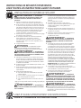
Using the hood controls.
Throughout this manual, features and appearance may vary from your model.
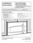
Switch Pad Controls (on some models)
Control Knobs (on some models)
ON
OFF
LO
MED
HI
HI
OFF
NITE
ON
OFF
OFF
LO
FAN Control
LIGHT Control
Turn to HI, MED or LO as needed.
Continuous use of the fan system while cooking helps
keep the kitchen comfortable and less humid. It also
reduces cooking odors and soiling moisture that create
a frequent need for cleaning.
Press the pad at the top to turn the light ON.
LIGHT Control
Turn to ON while cooking or to NITE for use as a night
light.
FAN Control
Press the pad at the top to turn the fan on HI and at the
bottom to turn it on LO. The center position is OFF.
Continuous use of the fan system while cooking helps
keep the kitchen comfortable and less humid. It also
reduces cooking odors and soiling moisture that create
a frequent need for cleaning.
Care and cleaning of the vent hood.
Be sure electrical power is off and all surfaces are cool before cleaning or servicing any part of the vent hood.
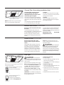
5HXVDEOH0HWDO*UHDVH)LOWHU³'XFWHG,QVWDOODWLRQV2QO\
Grease filter
The efficiency of your hood depends
on a clean filter. Frequency of cleaning
depends on hood use and the type of
cooking you do. However, the grease
filter should be cleaned at least once
a month.
To clean:
Soak and then agitate it in a hot water
and detergent solution. Light brushing
can be used to remove embedded
dirt. Rinse, shake and let it dry before
replacing.
To remove:
Pull down on the center of the front
edge of the filter. The filter will then
slip out of the retaining tabs on the
back.
NEVER OPERATE THE HOOD
WITHOUT THE FILTER IN PLACE.
With careful handling, the metal
filter will last for years. If a new
replacement filter becomes necessary,
order the part from your dealer. Order
genuine GE part number WB02X8391.
To replace:
Slip the back edge of the filter into the
retaining tabs and push the front edge
up until it snaps into place.
4
&KDUFRDO)LOWHU³5HFLUFXODWLQJ,QVWDOODWLRQV2QO\
Replaceable charcoal filter
NOTE: DO NOT rinse, or put charcoal
filters in an automatic dishwasher.
The charcoal filter cannot be cleaned.
It must be replaced. Order filter no.
WB02X10700. Replacement filters can be
ordered from your GE supplier.
If the hood is not vented to the outside, the
air will be recirculated through a disposable
charcoal filter that helps remove smoke and
odors.
The charcoal filter should be replaced after 6
to 12 months (depending on hood usage).
To remove:
Pull down on the center of the front edge
of the filter. The filter will then slip out of the
retaining tabs on the back.
To replace:
Slip the back edge of the filter into the
retaining tabs and push the front edge up
until it snaps into place.
Stainless Steel Surfaces (on some models)
Do not use a steel-wool pad; it will scratch
the surface.
To clean the stainless steel surface, use
warm sudsy water or a stainless steel cleaner
or polish. Always wipe the surface in the
direction of the grain. Follow the cleaner
instructions for cleaning the stainless steel
surface.
To inquire about purchasing stainless steel
appliance cleaner or polish, or to find the
location of a dealer nearest you, please call
RXUWROOIUHHQXPEHU
National Parts Center
800.626.2002
GEApplianceParts.com
Painted Surfaces (on some models)
Do not use steel-wool pads or other
abrasive cleaners. They will scratch the
surface.
Clean grease-laden surfaces of the hood
frequently. To clean the hood surface, use
a hot, damp cloth with a mild detergent
suitable for painted surfaces. About one
tablespoon of ammonia may be added to
the water. Use a clean, hot, damp cloth to
remove soap. Dry with a dry, clean cloth.
Light cover
or
GE Long Life Energy Smart™ A17
3URGXFW&RGH
'HVFULSWLRQ)/($;/&'
Available at www.gelighting.com
CAUTION:
When cleaning the
hood surfaces, be certain that you do not
touch the light bulb with moist hands or
cloth. A warm or hot light bulb may break if
touched with a moist surface. Always let the
light bulb cool completely before cleaning
around it.
Hood Light
CAUTION: Let the light bulb
When using an energy saving bulb in your GE hood
PDNHVXUH\RXXVHHLWKHU
GE Long Life Energy Smart™ Spiral® T2
3URGXFW&RGH
'HVFULSWLRQ)/(+76:&'
NOTE: When cleaning, take care not to
come in contact with filters and other nonenameled surfaces.
cool completely before removing. A warm or
hot bulb may break if touched with a moist
cloth or hand.
Remove the bulb and replace it with a type
A15 incandescent light bulb with an ordinary
screw base, not more than 60 Watts, or a
type A17 or T2 Compact Fluorescent (CFL)
light bulb with an ordinary screw base,
not more than 13 Watts. NOTE: Use only
incandescent bulbs in models RN328, JN327
and JV338.
IMPORTANT: For installation, handling and
disposal precautions, refer to the fluorescent
bulb packaging literature.
To remove the light cover
(on some models):
• Press the sides with two fingers until the
side prongs are released.
• Lift the light cover and slide it toward you
in one motion.
To replace the light cover:
• Insert the prong located at the end of the
cover into the top opening.
• Gently push the cover up and press the
sides to fit the side prongs into the side
openings.
• Release and the cover will lock in position.
5
Installation
Instructions
Range Hood
Questions? Call 800.GE.CARES (800.432.2737) or visit our Website at: GEAppliances.com
BEFORE YOU BEGIN
DUCTWORK REQUIREMENTS
NOTE: Read the ductwork sections only if you do not
have existing ductwork. If you have existing ductwork,
skip to the “Damage” section and proceed.
Read these instructions completely and carefully.
•
IMPORTANT – Save these instructions for
WARNING –
local inspector’s use.
•
TO REDUCE THE RISK OF FIRE AND
723523(5/<(;+$867$,5%(685(72'8&7$,52876,'(³
DO NOT VENT EXHAUST AIR INTO SPACES WITHIN WALLS OR
CEILINGS OR INTO ATTICS, CRAWL SPACES OR GARAGES.
7KHYHQWLQJV\VWHPPXVWH[KDXVWWRWKHRXWVLGH
This hood can be vented vertically through upper cabinets or
horizontally through an outside wall. Ductwork is not included.
IMPORTANT – Observe all governing
codes and ordinances.
•
•
•
•
•
•
Note to Installer – Be sure to leave these
instructions with the Consumer.
Note to Consumer – Keep these instructions
for future reference.
Skill level – Installation of this appliance requires
basic mechanical and electrical skills.
Completion time – 30 minutes–3 hours
Proper installation is the responsibility of the installer.
Product failure due to improper installation is not
covered under the Warranty.
Exhaust connection:
7KHKRRGH[KDXVWKDVEHHQGHVLJQHGWRPDWHZLWK
standard 31ø4s[s rectangular ducting or 7s diameter
round ducting.
If a 6s round duct is required, a rectangular-to-round
transition adaptor must be used*. Do not use less than a
6s diameter duct.
Maximum duct length:
For satisfactory air movement, the total duct length
of a 31ø4s[s rectangular, 6s or 7s diameter round
duct should not exceed 65 equivalent feet. See
the WORKSHEET–CALCULATE TOTAL EQUIVALENT
DUCTWORK LENGTH section.
FOR YOUR SAFETY:
WARNING –
Before beginning the
installation, switch power off at service panel and
lock the service disconnecting means to prevent power
from being switched on accidentally. When the service
disconnecting means cannot be locked, securely fasten
a prominent warning device, such as a tag, to the
service panel.
NOTE: It is important that ducting be installed using the
most direct route and with as few elbows as possible.
7KLVHQVXUHVFOHDUYHQWLQJRIH[KDXVWDQGKHOSVSUHYHQW
blockages. Also, make sure dampers swing freely and
nothing is blocking the ducts. When applicable, install any
makeup (replacement) air system in accordance with local
building code requirements. Visit GEAppliances.com for
available makeup air solutions.
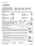
OPTIONAL POWER CORD KIT JXHC1
Elbows, transitions, wall and roofcaps, etc.,
present additional resistance to airflow and are equivalent
to a section of straight duct longer than their actual
physical size. When calculating the total duct length, add
the equivalent lengths of all transitions and adaptors plus
the length of all straight duct sections. The charts on the
following pages show you how to calculate total equivalent
GXFWZRUNOHQJWKXVLQJWKHDSSUR[LPDWHIHHWRIHTXLYDOHQW
length of some typical ducts.
* IMPORTANT: If a rectangular-to-round
transition adaptor is used, the bottom
corners of the damper will have to be
cut to fit, using the tin snips, in order
to allow free movement of the damper.
Equivalent lengths of duct pieces
are based on actual tests and reflect
requirements for good venting
performance with any hood.
An optional Power Cord Connection Kit, model JXHC1,
LVDYDLODEOHDWH[WUDFRVWIURP\RXU*(VXSSOLHUIRU
installation using a standard 3-prong, grounded wall
outlet. Follow the Installation Instructions packed with
the kit to connect the power cord to the range hood.
6
Installation Instructions
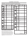
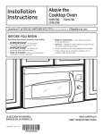
:25.6+((7³&$/&8/$7(727$/(48,9$/(17'8&7:25./(1*7+
DUCT
PIECES
EQUIVALENT NUMBER
LENGTH
x USED
31ø4s [s
Rect.,
straight
)W
[ =
)W
7s5RXQG )W
straight
[ 6s5RXQG )W
straight
[ 31ø4s [s
Rect. 90°
elbow
)W
[ )W
31ø4s [s
Rect. 45°
elbow
)W
[ )W
31ø4s [s
Rect. 90°
flat elbow
)W
[ )W
31ø4s [s
Rect.
wall cap
with
damper
)W
IWZR
damper)
[ )W
[ )W
31ø4s [s
Rect. to
6s round
transition
)W
[ )W
31ø4s [s
Rect. to
6s round
transition
90° elbow
)W
[ )W
)W
)W
6s5RXQG )W
90° elbow
[ )W
6s5RXQG )W
45° elbow
[ )W
)W
6XEWRWDOFROXPQ
DUCT
PIECES
TOTAL
MAXIMUM DUCT LENGTH: For satisfactory air movement,
the total duct length of a 31ø4s[s rectangular, 7s diameter
round duct should not exceed 65 equivalent feet.
NOTE: Any home ventilation system, such as a ventilation
hood, may interrupt the proper flow of combustion air and
H[KDXVWUHTXLUHGE\ILUHSODFHVJDVIXUQDFHVJDVZDWHU
heaters and other naturally vented systems. To minimize the
chance of interruption of such naturally vented systems, follow
the heating equipment manufacturer’s guidelines and safety
standards such as those published by NFPA and ASHRAE.
When applicable, install any makeup (replacement) air system
in accordance with local building code requirements. Visit
GEAppliances.com for available makeup air solutions.
EQUIVALENT
NUMBER
LENGTH
X USED
= TOTAL
6s 5RXQG )W
wall cap IWZR
with
damper)
damper
[ )W
[ )W
6s 5RXQG )W
roof cap
[ )W
6s5RXQG )W
to
31ø4s [s
rect.
transition
[ )W
6s5RXQG )W
to
31ø4s [s
rect.
transition
90° elbow
[ )W
7s5RXQG )W
90° elbow
[ )W
7s5RXQG )W
45° elbow
[ )W
7s 5RXQG )W
wall cap (IWZR
with
damper)
damper
[ )W
[ )W
7s 5RXQG )W
roof cap
[ )W
7s5RXQG )W
to
31ø4s [s
rect.
transition
[ )W
7s Round )W
to
31ø4s [s
rect.
transition,
90° elbow
[ )W
6XEWRWDOFROXPQ
)W
6XEWRWDOFROXPQ
)W
=
Ft.
Total ductwork
7
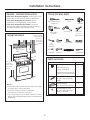
Installation Instructions
DAMAGE – SHIPMENT/INSTALLATION
TOOLS YOU WILL NEED
• If the unit is damaged in shipment, return the unit to the
store in which it was bought for repair or replacement.
• If the unit is damaged by the customer, repair or
replacement is the responsibility of the customer.
• If the unit is damaged by the installer (if other than
the customer), repair or replacement must be made by
arrangement between customer and installer.
MOUNTING SPACE
24s,30s or 36s to
match cooktop
width
Flat-blade and Phillips
screwdrivers
Saw (saber or
keyhole)
Bottom edge of
cabinet needs
to be 30s or
more from
the cooking
surface
Pencil
Electric drill
s
pivoting
KH[VRFNHW
Pliers
Tape measure
Flashlight
Caulking
Level
Duct tape
Metal snips
(in some
applications)
Wire stripper
30s
min.
s Nutdriver
PARTS INCLUDED
66s or more
from the
floor to the
top of the
hood
PART
NOTES:
• Hood width may be greater than the width of the range
or cooktop, but it may not be smaller.
• Ensure the range or cooktop is installed per
manufacturer’s installation instructions.
• If you are going to vent your range hood to the outside,
VHHWKH´'XFWLQJ5HTXLUHPHQWVµVHFWLRQIRUH[KDXVWGXFW
preparation.
Grease Filter only (JV338)
1
Charcoal Filter only
(JN327 and RN328)
1
Grease Filter and Charcoal Filter
(JV24X, JV347, JV348 and JV367)
2
Mounting Screws
(8 - 18s[s Phillips pan
head)
4
([KDXVW$GDSWRU
(for 31ø4s[s rect. venting)
([KDXVW$GDSWRU6FUHZ
(8 - 18s[s Phillips pan
KHDGRUKH[KHDG
8
QUANTITY
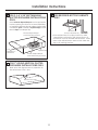
Installation Instructions
1 CHOOSE VENT OPTION
IMPORTANT: If the hood is to be installed in a
recirculating, non-vented, ductless manner, do not
knock out any vent openings in the hood. Only an
electrical access hole will be knocked out of the hood.
Determine the vent option that your installation will
require and that is available for your model from the
below choices.
A
Outside top exhaust
(Vertical duct–3-1/4s x 10s Rectangular)
C
Outside rear exhaust
(Horizontal duct–3-1/4s x 10s Rectangular)
JV338
JV338
JV247
JV248
JV347
JV348
JV367
JV247
JV248
JV347
JV348
JV367
B
D
Outside top exhaust
(Vertical duct–7s Round)
Recirculating
(non-vented/ductless)
JV338
JN327
RN328
JV247
JV248
JV347
JV348
JV367
JV247
JV248
JV347
JV348
JV367
9
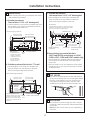
Installation Instructions
2 REMOVE EXHAUST ADAPTOR
5 REMOVE WIRING COVER
If exhausting/venting using the 34s1ø x 10s rectangular
GXFW³RSWLRQDOIRU-9-9-9-9-9
DQG-9PRGHOVRQO\
5HPRYHWKHH[KDXVWDGDSWRUIURPWKHLQVLGHRIWKHKRRG
Set it aside along with its mounting screws.
Remove the wiring cover from inside the hood.
Set the cover and its mounting screws aside.
Wiring
cover
31ø4s[s
rectangular
H[KDXVW
adaptor
and screws
6 REMOVE WIRING KNOCKOUT
3 REMOVE FILTER
Remove either the top or the back wiring knockout as
needed and install an approved strain relief clamp.
Remove the shipping tape holding the metal grease
filter in place. Pull down on the center of the front edge
of the filter. The filter will then slip out of the retaining
tabs on the back.
Top
knockout
Back
knockout
Strain relief
clamp
Strain relief
clamp
Metal grease filter
7 REMOVE DUCT KNOCKOUT
If recirculating, non-vented ductless (JN327 and RN328,
and optional for JV247, JV248, JV347, JV348 and JV367
models only), skip to Step 11 D and proceed.
Using a flat-blade screwdriver, remove the appropriate
duct knockout from the top or back of the hood.
4 REVERSE THE BAFFLE FOR
DUCTED INSTALLATIONS ONLY -9
-9-9-9DQG-9PRGHOV
,IWKHKRRGLVWREHUHFLUFXODWHGVNLSWRWKHQH[WVWHS
Remove the baffle from the top of the hood. Reinstall
the baffle so the short side marked “VENTED” is visible.
The long side of the baffle should be inside the hood.
31ø4s x 10s Rectangular
vertical discharge.
Remove top rectangular
duct knockout only.
“VENTED” is visible
7 s Round vertical discharge.
Remove circular duct
knockout only.
31ø4s x 10s Rectangular horizontal
discharge. Remove rear
rectangular duct knockout only.
10
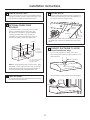
Installation Instructions
10 FOR RECESSED-BOTTOM CABINETS
FOR 3-1-4s X 10s RECTANGULAR
ONLY
DUCTED DISCHARGE INSTALLATIONS
ONLY:
Attach exhaust adaptor/damper over the appropriate
knockout opening (for vertical or horizontal, depending
RQLQVWDOODWLRQZLWKWZRH[KDXVWDGDSWRUVFUHZV0DNH
sure damper pivot is nearest to top/back edge of hood.
Remove tape from damper flap.
([KDXVWDGDSWRUGDPSHU
(vertical discharge position)
Pivot
(depending on
installation)
Wood shims
(minimum thickness s
• If the cabinets have front, side or back trim, make
ZRRGVKLPVDPLQLPXPRIs thick and cut to fit
the width of the inner recessed cabinet bottom. Attach
them to the cabinet bottom recess on both sides. See
Step 11 for marking locations.
Tape
7RSEDFNHGJH
([KDXVWDGDSWRUGDPSHU
(horizontal discharge position)
9 FOR 7s ROUND VERTICAL DUCTED
DISCHARGE INSTALLATIONS ONLY:
Bend up the duct alignment ears in preparation for
later attachment of the 7s duct.
Attachment ear tabs
11
Installation Instructions
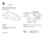
11 MARK HOLES
C. Outside rear exhaust
(Horizontal duct–3-1/4sx 10s Rectangular)
Select the vent option that your installation will require
DQGSURFHHGWRWKDWVHFWLRQ
• Use the diagram or the hood as a template and
mark the locations on the cabinet for ductwork,
electrical wiring and keyhole screw slots.
A. Outside top exhaust
(Vertical duct–3-1/4sx 10s Rectangular)
• Use the diagram or the hood as a template and mark
the locations on the cabinet for ductwork, electrical
wiring and keyhole screw slots.
Wood shims
(recessed-bottom cabinets only–shims must be
DPLQLPXPRIs thick and cut to fit the width
of the inner recessed cabinet bottom)
Cabinet front
Hood mounting screws (4)
103ø4s (24s hood)
133ø4s (30s hood)
163ø4s (36s hood)
Cabinet front
103ø4s (24s hood)
133ø4s (30s hood)
163ø4s (36s hood)
73ø4s
Cabinet Bottom
51ø4s
51ø4s
3øs
Vertical duct
access hole
34
12
øs
Wood shims
(recessed-bottom
cabinets only–shims
must be a minimum
RIs thick and cut
to fit the width of
the inner recessed
cabinet bottom)
Center
line
Cabinet
bottom
Hood mounting
screws (4)
13ø8s
Electrical access hole
(in cabinet bottom)
Hood mounting screws (4)
Cabinet
bottom
Access
hole for 7s
round duct
51ø4s
51ø4s
73ø4s
103ø4s (24s hood)
133ø4s (30s hood)
163ø4s (36s hood)
Center line
Electrical access
hole (in wall)
• Use the hood as a template and mark the locations
on the cabinet for the electrical wiring and keyhole
screw slots.
• Since the hood is to be recirculated (not to be vented
outside), do not cut out any vent openings in the wall
or cabinet bottom.
• Use the diagram or the hood as a template and
mark the locations on the cabinet for ductwork,
electrical wiring and keyhole screw slots.
12 CUT HOLES
Cut holes at marked locations for duct and electrical
ZLULQJ)RUWKHYHUWLFDOGXFWFXWRXWsH[WUDWRZDUG
the front of the cabinet so you can move the duct
freely when installing the hood. It may also ease
installation by cutting the hole 10 1ø2s instead of 10s.
103ø4s (24s hood)
133ø4s (30s hood)
163ø4s (36s hood)
Cabinet front
11ø4s
D.Recirculating (non-vented ductless–
-1DQG51DQGRSWLRQDORQ-9
-9-9-9DQG-9PRGHOVRQO\
B. Outside top exhaust (Vertical duct–7s Round)
103ø4s (24s hood)
133ø4s (30s hood)
163ø4s (36s hood)
øs
Horizontal duct
access hole
103ø4s (24s hood)
133ø4s (30s hood)
163ø4s (36s hood)
95ø8s
11ø4s
33ø4s
12
73ø4s
8s DIA.
HOLE
Wood shims (recessedbottom cabinets only–shims Center
PXVWEHDPLQLPXPRIs
line
thick and cut to fit the width
of the inner recessed cabinet
bottom)
5øs
34
11ø4s
95ø8s
13ø8s
Electrical access
hole (in cabinet bottom)
13 RUN WIRES
Run the electrical wires through the wall or cabinet
according to National Electrical Code and applicable
local codes.
NOTE: DO NOT turn the power on until installation is
complete.
12
Installation Instructions
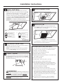
14 SCREW IN PART WAY
17 SECURE HOOD
Drive a mounting screw (from the hardware packet)
part way into each center of the narrow neck of the
keyhole slots marked on the cabinet bottom.
Slide the hood back against the wall. Tighten the
mounting screws. Be sure the screw heads are in
the narrow neck of the keyhole slot.
15 OPTIONAL POWER CORD
.,7-;+&
Mounting
screw (4)
An optional Power Cord Connection Kit, model
-;+&LVDYDLODEOHDWH[WUDFRVWIURP\RXU
GE supplier for installation using a standard
3-prong, grounded wall outlet. Follow the
Installation Instructions packed with the kit to
connect the power cord to the range hood.
CL
73ø4s
Keyhole (4)
NOTE: DO NOT PUSH ON THE FAN BLADE. Pushing on
the blade may cause it to interfere with other hood
parts.
Cabinet
11ø4s
CONNECT DUCTWORK TO HOOD
(Ducted installations only)
3-prong
wall outlet
(if using cord
connection)
On 7s round installations, attach the 7s duct
with sheet metal screws through the holes in the
alignment ears.
7s round duct
13ø4sdia. clearance hole
for optional power
supply location
NOTE: If using optional Power Cord Kit JXHC1, feed
the power cord through the hole in the top cabinet
ZKLOHUDLVLQJWKHKRRG/RRSDQ\H[FHVVOHQJWKRI
cord and tie away with a suitable tape or tie.
Attachment ear tabs
Use duct tape to make joints secure and airtight.
16 FEED IN WIRES
Lift the hood into position and feed the house wiring
through the wiring knockout.
Duct tape
13
Installation Instructions
22 REPLACE WIRING COVER
19 INSTALL LIGHT BULB
NOTE: A light bulb is not shipped with the hood.
Obtain one locally. Purchase and install a type A15
incandescent light bulb with an ordinary screw
base, not more than 60 Watts, or a type A17 or T2
Compact Fluorescent (CFL) light bulb with an ordinary
screw base, not more than 13 Watts. NOTE: Use only
incandescent bulbs in models RN328, JN327 and JV338.
IMPORTANT: For installation, handling and disposal
precautions, refer to the fluorescent bulb packaging literature.
Wiring cover
23 REPLACE FILTER
Make sure fan blade turns freely and replace the
filter. NOTE: Install the metal grease filter if ducted or
the charcoal filter if recirculated.
When using an energy saving bulb in your GE hood, make sure you use
HLWKHU
GE Long Life Energy
Smart™ Spiral® T2
3URGXFW&RGH
'HVFULSWLRQ
)/(+76:&'
or
GE Long Life Energy
Smart™ A17
3URGXFW&RGH
'HVFULSWLRQ
)/($;/&'
Available at
www.gelighting.com
Metal grease filter or charcoal filter
The installation is complete. Turn on power at service
panel, and test for proper operation.
20 FOLLOW ELECTRICAL CODE
Complete the electrical wiring according to National
Electrical Code and local codes.
NOTE: This hood must be permanently grounded.
Connect house wiring (120 VAC) to hood wiring.
TROUBLESHOOTING CHECKLIST
If the hood seems to be operating at high speed when
the control is not set on high, or if ventilation seems
LQDGHTXDWHFKHFNWKHIROORZLQJ
❏ Knockouts not removed from hood.
❏ Damper blade not opening.
❏ Reduced airflow because the duct is too small or the
duct length is too long.
❏ The duct is blocked.
❏ Undersized or restrictive wall or roof cap.
21 CONNECT WIRING
Connect house black to hood black wire, house white
to hood white wire and house ground under green
ground screw. Securely tighten the strain relief clamp
onto the house wiring.
,IWKHKRRGVHHPVWRPDNHH[FHVVLYHQRLVH
❏ Fan may be hitting the filter. Turn off the fan and
remove the filter. Bend the filter down slightly in the
center (into a dome shape) to allow fan clearance.
Reinstall and adjust as needed.
Green ground
screw
7KHIDQGRHVQRWZRUNEXWWKHOLJKWVGR
❏ Switch power off at the service panel and lock the
service disconnecting means to prevent power from
being switched on accidentally. When the service
disconnecting means cannot be locked, securely
fasten a prominent warning device, such as a tag, to
the service panel.
❏ Check the wiring connections. See the CONNECT
WIRING section in these Installation Instructions.
WARNING:
IMPROPER CONNECTION OF
ALUMINUM HOUSE WIRING TO THESE COPPER LEADS
CAN RESULT IN A SERIOUS PROBLEM. USE ONLY
CONNECTORS DESIGNED FOR JOINING COPPER TO
ALUMINUM AND FOLLOW THE MANUFACTURER’S
RECOMMENDED PROCEDURE CLOSELY.
14
GE Range Hood Warranty.
All warranty service provided by our Factory Service Centers, or an
authorized Customer Care® technician. To schedule service, visit us
on-line at GEAppliances.com, or call 800.GE.CARES (800.432.2737).
Please have serial number and model number available when
calling for service.
Staple your receipt here.
Proof of the original purchase
date is needed to obtain service
under the warranty.
For The Period Of: GE Will Replace:
One Year
From the date of the
original purchase
Any part of the range hood which fails due to a defect in materials or workmanship.
During this limited one-year warranty, GE will also provide, free of charge, all labor and
in-home service to replace the defective part.
What GE Will Not Cover:
■ Service trips to your home to teach you how to use
the product.
■ Improper installation, delivery or maintenance.
■ Failure of the product if it is abused, misused, or
used for other than the intended purpose or used
commercially.
■ Replacement of house fuses or resetting of circuit breakers.
■ Damage to the product caused by accident, fire, floods
or acts of God.
■ Incidental or consequential damage caused by possible
defects with this appliance.
■ Damage caused after delivery.
■ Product not accessible to provide required service.
■ Installation or service for a makeup (replacement) air
system.
(;&/86,212),03/,(':$55$17,(6³<RXUVROHDQGH[FOXVLYHUHPHG\LVSURGXFWUHSDLUDVSURYLGHGLQWKLV
Limited Warranty. Any implied warranties, including the implied warranties of merchantability or fitness
for a particular purpose, are limited to one year or the shortest period allowed by law.
This warranty is extended to the original purchaser and any succeeding owner for products purchased for home
use within the USA. If the product is located in an area where service by a GE Authorized Servicer is not available, you
may be responsible for a trip charge or you may be required to bring the product to an Authorized GE Service Location for
service. In Alaska, the warranty excludes the cost of shipping or service calls to your home.
Some states do not allow the exclusion or limitation of incidental or consequential damages. This warranty gives
you specific legal rights, and you may also have other rights which vary from state to state. To know what your
legal rights are, consult your local or state consumer affairs office or your state’s Attorney General.
Warrantor: General Electric Company. Louisville, KY 40225
15
Consumer Support.
GE Appliances Website
GEAppliances.com
Have a question or need assistance with your appliance? Try the GE Appliances Website 24 hours a day,
any day of the year! For greater convenience and faster service, you can now download Owner’s Manuals,
order parts or even schedule service on-line.
Schedule Service
GEAppliances.com
([SHUW*(UHSDLUVHUYLFHLVRQO\RQHVWHSDZD\IURP\RXUGRRU*HWRQOLQHDQGVFKHGXOH\RXUVHUYLFHDW
your convenience any day of the year! Or call 800.GE.CARES (800.432.2737) during normal business hours.
Real Life Design Studio
GEAppliances.com
*(VXSSRUWVWKH8QLYHUVDO'HVLJQFRQFHSW³SURGXFWVVHUYLFHVDQGHQYLURQPHQWVWKDWFDQEHXVHGE\
people of all ages, sizes and capabilities. We recognize the need to design for a wide range of physical and
mental abilities and impairments. For details of GE’s Universal Design applications, including kitchen design
ideas for people with disabilities, check out our Website today. For the hearing impaired, please call 800.TDD.
GEAC (800.833.4322).
Extended Warranties
GEAppliances.com
3XUFKDVHD*(H[WHQGHGZDUUDQW\DQGOHDUQDERXWVSHFLDOGLVFRXQWVWKDWDUHDYDLODEOHZKLOH\RXUZDUUDQW\
is still in effect. You can purchase it on-line anytime, or call 800.626.2224 during normal business hours.
*(&RQVXPHU+RPH6HUYLFHVZLOOVWLOOEHWKHUHDIWHU\RXUZDUUDQW\H[SLUHV
Parts and Accessories
GEApplianceParts.com
Individuals qualified to service their own appliances can have parts or accessories sent directly to their homes
(VISA, MasterCard and Discover cards are accepted). Order on-line today, 24 hours every day or
by phone at 800.626.2002 during normal business hours.
Instructions contained in this manual cover procedures to be performed by any user. Other servicing generally
VKRXOGEHUHIHUUHGWRTXDOLILHGVHUYLFHSHUVRQQHO&DXWLRQPXVWEHH[HUFLVHGVLQFHLPSURSHUVHUYLFLQJPD\
cause unsafe operation.
Contact Us
GEAppliances.com
If you are not satisfied with the service you receive from GE, contact us on our Website with all the details
LQFOXGLQJ\RXUSKRQHQXPEHURUZULWHWR *HQHUDO0DQDJHU&XVWRPHU5HODWLRQV
GE Appliances, Appliance Park
Louisville, KY 40225
Register Your Appliance
GEAppliances.com
5HJLVWHU\RXUQHZDSSOLDQFHRQOLQH³DW\RXUFRQYHQLHQFH7LPHO\SURGXFWUHJLVWUDWLRQZLOODOORZIRUHQKDQFHG
communication and prompt service under the terms of your warranty, should the need arise.
You may also mail in the pre-printed registration card included in the packing material.
Printed in China