1
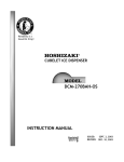
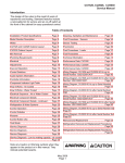
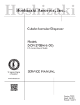
Reliability is a
beautiful thingTM
CUBELET ICE DISPENSER
DCM-270BAH-OS
SERVICE MANUAL
ITEM #:
73110
ISSUED: February 10, 2004
REVISED:
May 26, 2005
IMPORTANT
Only qualified service technicians should attempt to service or maintain this ice
dispenser. No service or maintenance should be undertaken until the technician
has thoroughly read this service manual.
HOSHIZAKI provides this manual primarily to assist qualified service technicians in the
service and maintenance of the dispenser.
Should the reader have any questions or concerns which have not been satisfactorily
addressed, please call or write to the HOSHIZAKI Technical Support Department for
assistance.
HOSHIZAKI provides this manual primarily to assist qualified service technicians in the
service and maintenance of the dispenser.
Should the reader have any questions or concerns which have not been satisfactorily addressed, please call or write to the HOSHIZAKI Technical Support Department for
assistance.
HOSHIZAKI AMERICA, INC.
618 Highway 74 South
Peachtree City, GA 30269
Attn: HOSHIZAKI Technical Support Department
Phone: 1-800-233-1940 Technical Service
(770) 487-2331
Fax:
(770) 487-3360
Web Site: www.hoshizakiamerica.com
NOTE:
To expedite assistance, all correspondence/communication MUST include the
following information:
• Model Number
• Serial Number
• Complete and detailed explanation of the problem
2
Please review this manual. It should be read carefully before the ice dispenser is serviced
or maintenance operations performed. Only qualified service technicians should service
and maintain the dispenser. This manual should be made available to the technician prior to
service or maintenance.
CONTENTS
I. Specifications .................................................................................................................... 4
1. DCM-270BAH-OS (air-cooled) ..................................................................................... 4
II. General Information .......................................................................................................... 5
1. Construction ................................................................................................................. 5
2.Operation - How it works ............................................................................................... 6
III. Technical Information ....................................................................................................... 7
1. Water Circuit and Refrigerant Circuit............................................................................. 7
2. Performance Data ......................................................................................................... 8
[a] DCM-270BAH-OS (air-cooled) .............................................................................. 8
3. Wiring Diagram ............................................................................................................. 9
4. Sequence of Electrical Circuit .................................................................................... 10
IV. Service Diagnosis .......................................................................................................... 20
1. No Ice Production ....................................................................................................... 20
2. Low Ice Production ..................................................................................................... 22
3. Faulty Dispenser......................................................................................................... 23
[a] Optical Sensor Description .................................................................................. 23
4. Other ........................................................................................................................... 25
V. Removal and Replacement of Components ................................................................... 26
1. Service for Refrigerant Lines ...................................................................................... 26
[a] Refrigerant Recovery........................................................................................... 26
[b] Evacuation and Recharge [R-404A] .................................................................... 26
2. Brazing ....................................................................................................................... 27
3. Removal and Replacement of Compressor ................................................................ 28
4. Removal and Replacement of Drier ........................................................................... 29
5. Removal and Replacement of Thermostatic Expansion Valve ................................... 30
6. Removal and Replacement of Pressure Switch ......................................................... 31
7. Removal and Replacement of Control Water Valve .................................................... 32
8. Removal and Replacement of Flush Water Valve ....................................................... 33
9. Removal and Replacement of Float Switch................................................................ 34
10. Removal and Replacement of Bin Control Switch Assembly ................................... 35
11. Removal and Replacement of Storage Bin Assembly .............................................. 36
12. Removal and Replacement of Agitator and Drip Ring .............................................. 37
13. Removal and Replacement of Evaporator Assembly ............................................... 38
VI. Cleaning and Maintenance Instructions ........................................................................ 41
1. Preparing the Ice Dispenser for Long Storage ............................................................ 41
2. Cleaning Instructions .................................................................................................. 42
[a] Cleaning Procedure ............................................................................................ 42
[b] Sanitizing Procedure ........................................................................................... 45
2. Maintenance Instructions ............................................................................................ 46
3
I. Specifications
1. DCM-270BAH-OS (air-cooled)
AC SUPPLY VOLTAGE
AMPERAGE
MAXIMUM FUSE SIZE
MINIMUM CIRCUIT AMPACITY
APPROXIMATE ICE PRODUCTION
PER 24 HR.
lbs./day ( kg/day )
Reference without *marks
SHAPE OF ICE
ICE QUALITY
APPROXIMATE STORAGE CAPACITY
ELECTRIC & WATER CONSUMPTION
ELECTRIC W (kWH/100 lbs.)
POTABLE WATER
gal./24HR (gal./100 lbs.)
EXTERIOR DIMENSIONS (WxDxH)
EXTERIOR FINISH
WEIGHT
CONNECTIONS - ELECTRIC
- WATER SUPPLY
- DRAIN
ICE MAKING SYSTEM
HARVESTING SYSTEM
ICE MAKING WATER CONTROL
COOLING WATER CONTROL
DISPENSER CONTROL SYSTEM
BIN CONTROL SYSTEM
COMPRESSOR
CONDENSER
EVAPORATOR
REFRIGERANT CONTROL
REFRIGERANT CHARGE
DESIGN PRESSURE
COMPRESSOR PROTECTION
GEAR MOTOR PROTECTION
REFRIGERANT CIRCUIT PROTECTION
LOW WATER PROTECTION
ACCESSORIES - SUPPLIED
OPERATING CONDITIONS
115/60/1
8.5 A [AT 104°F(40°C)/WT 80°F(27°C)]
N/A
N/A
WATER TEMP. (°F)
Ambient
50
70
90
Temp.(°F)
70
* 288 (131) 276 (125) 265 (120)
80
254 (115) 243 (110) 233 (106)
90
224 (101) * 220 (100) 205 (93)
100
197 (89)
189 (86) * 176 (80)
Cubelet (Compressed Flake Ice)
Approx. 90%, Ice (90/70°F, Conductivity 200 µs/cm)
8.8 lbs.
90/70°F
70/50°F
669 (7.3)
638 (5.3)
26 (12)
35 (12)
16-9/16" x 24-1/8" x 31-11/16" (420 x 613 x 805mm)
Stainless Steel
Net 152 lbs. ( 69 kg ), Shipping 170 lbs. ( 77kg )
Cord Connection
Inlet 1/2" FPT
Outlet 3/4" FPT
Auger type
Direct Driven Auger ( 80W Gear Motor )
Float Switch
N/A
Photoelectric Sensor (Infrared)
Mechanical Bin Control ( Proximity Sw. )
Hermetic,
Model ASE24C3E
Air-cooled, Fin and Tube Type
Copper Tube on Cylinder
Thermostatic Expansion Valve
14.8 oz.
R-404A,
(420 g)
High 460 PSIG, Low 290 PSIG
Auto-reset Overload Protector
Manual reset Circuit Breaker
Auto-reset High Pressure Control Switch
Float Switch and Timer
N/A
VOLTAGE RANGE
104 - 127 V
AMBIENT TEMP.
45 - 100° F
WATER SUPPLY TEMP.
45 - 90° F
WATER SUPPLY PRESSURE
10 - 113 PSIG
We reserve the right to make changes in specifications and design without prior notice.
4
II. General Information
1. Construction
The Hoshizaki Cubelet Ice Dispenser, model DCM-270BAH-OS includes water supply,
freezer, condensing, storage, dispensing and control assemblies.
Fig. 1
Note: *Adjustable Legs
Minimum height - 4"
Maximum height - 5.3"
Do not adjust exceeding the above recommendation.
5
2.Operation - How it works
Water flows from the potable water source through the water supply line shut-off valve,
enters at the water inlet fitting and into the water reservoir. The water reservoir functions to
maintain a constant water level inside the freezer assembly. Water from the water reservoir
enters at the bottom of the freezer. Heat is removed by the refrigeration process and ice forms
inside the freezer.
A stainless steel auger, located inside the freezer, is direct-driven by the gear motor, and the
rotating auger carries the ice upward to the end of the auger, where excess water is pressed
out of the ice, as the ice is extruded and broken into cubelet ice (compressed ice) and then
pushed out into the storage bin.
Moving the power switch on the bottom left of the middle front panel, to the “ON” position
starts the automatic and continuous icemaking process. When the ice storage bin is filled
with ice, the bin control switch will shut off the icemaking process. As the ice is removed from
the storage bin, the bin control switch resets automatically and restarts the icemaking
process.
The agitator in the storage bin keeps the ice from clustering so that the ice can move easily
through the spout.
Fig. 2
6
III. Technical Information
1. Water Circuit and Refrigerant Circuit
7
2. Performance Data
[a] DCM-270BAH-OS (air-cooled)
Note: Pressure data is recorded first 5 minutes in freezing cycle. The data without
*marks should be used for reference.
We reserve the right to make changes in specifications and design without prior notice.
8
3. Wiring Diagram
9
4. Sequence of Electrical Circuit
POWER ON
WATER STARTS TO BE SUPPLIED TO
RESERVOIR
AGITATION TIMER ON - (2 SEC.)
10
RESERVOIR FILLS UP
GEAR MOTOR TURNS ON
11
COMPRESSOR STARTS
60 SEC. AFTER GEAR MOTOR.
12
ICE MAKING CONTINUES.
START CAPACITOR TAKEN
OUT OF CIRCUIT
13
BIN CONTROL TRIPS.
COMPRESSOR STOPS
90 SECONDS LATER.
14
GEAR MOTOR STOPS
60 SECONDS AFTER
COMPRESSOR.
15
DISPENSE ICE
(BIN CONTROL STILL TRIPPED)
16
FLUSH SWITCH ACTIVATED.
17
FLUSH TIMER ACTIVATED.
18
AGITATION TIMER ACTIVATES
GEAR MOTOR.
19
IV. Service Diagnosis
1. No Ice Production
PROBLEM
[1] The ice dispenser will
not start.
POSSIBLE CAUSE
a) Power Supply Cord
b) Power Switch (on left
bottom of front panel)
c) Fuse 1A (Control Box)
[2] Water valve operates, a) Water Supply Line
but no ice is produced.
b) Water Valve
c) Water Control Relay
[3] Compressor will not
start.
4. Blown fuse.
1. OFF position.
1. Blown out.
1. Shut-off valve closed.
2. Water supply off.
1. Clogged.
1. Bad contacts (terminal
nos. 4 and 6).
d) Timer
2. Coil winding opened.
3. Loose connections.
1. Bad contacts.
a) Compressor
2.
3.
4.
1.
b) Timer
c) Motor Protector
d) Starter
[4] Gear motor will not
start.
1. Broken or loose
connection.
2. Loose connection.
3. Bad contacts.
e) Starting Capacitor
a) Gear Motor
b) Timer
c) Protect Relay
d) Protector
e) Capacitor
REMEDY
1. Check for contintinuity and
replace.
2. Tighten.
3. Check for contintinuity and
replace.
4. Replace.
1. Move to ON position.
1. Check for short circuit and
replace.
1. Open.
2. Check and get
recommended pressure.
1. Clean.
1. Check for continuity and
replace.
2. Replace.
3. Tighten.
1. Check for continuity and
replace.
2. Replace.
3. Tighten.
4. Replace.
1. Replace.
Coil winding opened.
Loose connections.
Defective.
Motor winding opened
or grounded.
1. Bad contacts (X2 relay). 1. Check for continuity and
replace.
2. X2 relay coil winding
2. Replace.
opened.
3. Loose connections.
3. Tighten.
1. Bad contacts.
1. Check for continuity and
replace.
1. Bad contacts.
1. Check for continuity and
replace.
1. Defective.
1. Replace.
1. Motor winding opened. 1. Replace.
1. Bad contacts (X1 relay). 1. Check for continuity and
replace.
1. Bad contacts.
1. Check for continuity and
replace.
2. Coil winding opened.
2. Replace.
3. Loose connections.
3. Tighten.
1. Bad contact.
1. Check for continuity and
replace.
1. Defective.
1. Replace.
20
PROBLEM
POSSIBLE CAUSE
[5] Fan motor will not start. a) Fan Motor
b) Timer
REMEDY
1. Motor winding opened. 1. Replace.
2. Bearing worn out.
2. Replace.
3. Wiring to fan motor.
3. Check for loose connection
or open, and replace.
4. Fan blade bound.
4. Check and replace.
1. Bad contacts (X2 relay). 1. Check for continuity and
replace.
2. X2 relay coil winding
opened.
[6] No water or poor flow. a) Water Supply
3. Loose connections.
1. Water failure or
pressure too low.
2.
b) Water Valve
c) Float Switch
d) Water Control Relay
1.
2.
1.
2.
1.
2.
[7] Ice dispenser will not
stop even if out of
water.
e) Bin Control Switch
1.
f) Ice Making Switch
1.
2.
a) Float Switch
1.
2.
1.
b) Water Control Relay
21
2. Replace.
3. Tighten.
1. Wait until water is supplied
or adjust the pressure range
within 10-113 PSIG.
Shut-off valve closed or 2. Open.
restricted.
Clogged filter.
1. Clean.
Coil winding opened.
2. Replace.
Contacts fused.
1. Replace.
Clogged.
2. Clean.
Bad contacts (terminal 1. Check for continuity and
nos. 1 and 5).
replace.
Contacts fused
2. Replace.
(terminal nos. 3 and 5).
Bad contacts.
1. Check for continuity and
replace.
"OFF" position.
1. Move to "ON" position.
Bad contacts.
2. Check for continuity and
replace.
Contacts fused.
1. Replace.
Clogged.
2. Clean.
Contacts fused
1. Replace.
(terminal nos. 4 and 6).
2. Low Ice Production
PROBLEM
POSSIBLE CAUSE
[1] Abnormal refrigeration a) Condenser
circuit.
1. Dirty air filter or
condenser.
2. Bad ventilation.
REMEDY
1. Clean.
2. Remove anything blocking
vents.
b) Thermostatic Expansion 1. Low-side pressure or
1. Secure bulb to low-side line
Valve
temperature exceeding
or replace.
the limit.
c) Refrigerant Lines
1. Gas leaks.
1. Check for leaks with a leak
detector. Reweld leak,
replace drier and charge
with refrigerant. The amount
of refrigerant is marked on
the nameplate.
d) Compressor Motor
Protector
2. Overcharged.
2. Recharge.
1. Overload protector
stops compressor
intermittently.
1. Check condenser and fan
motor.
e) Inside Wall of Evaporator 1. Scale on inside wall of
freezing cylinder.
1. Remove auger, use
Hoshizaki "Scale Away" or
"LIME-A-WAY" solution to
clean periodically.
If water is found to exceed
the following levels, install a
conditioner:
Hardness 50 ppm
Silica 30 ppm
[2] Condensing
temperature too high.
a) Condenser
1. Dirty air filter or
condenser.
2. Bad ventilation.
1. Clean.
3. Ambient temperature
too high.
3. Check ventilation and
location, and change as
needed.
2. Remove anything blocking
vents.
4. Less than 6" clearance 4. Allow proper clearance for
at rear, sides and top.
ventilation.
b) Fan Motor
[3] Poor water flow.
a) Water Supply
1. Fan revolving too
1. See chart 1,[5], a)
slowly.
1. Water pressure too low. 1. See chart 1,[6], a)
22
3. Faulty Dispenser
PROBLEM
[1] No ice is dispensed.
POSSIBLE CAUSE
a) Storage Bin
1. Ice block or bridge.
2. Incorrect wiring.
1. Deformed due to ice
block or bridge.
c) Solenoid
1. Coil winding opened.
d) Ice switch or dispensing 1. Bad contacts.
sensor.
e) Ice Dispensing Relay
1. Bad contacts.
b) Agitator
[2] No water is dispensed. a) Water Valve
(Dispensing)
b) Water Dispensing
Sensor
[3] Ice keeps being
a) Shutter
dispensed.
b) Ice Switch
Dispensing Switch
1. Clogged filter.
1. Bad circuit.
1. Faulty adjustment.
1. Contacts fused.
REMEDY
1. Remove all ice from storage
bin when not using ice
dispenser for a long time.
2. Correct wiring.
1. Replace.
1. Replace.
1. Check for continuity and
replace.
1. Check for continuity and
replace.
1. Clean.
1. Check for continuity and
replace.
1. With shutter closed, lock
shutter in place by securing
with two screws at the lower
part of the solenoid and two
screws under solenoid.
1. Replace.
[a] Optical Sensor Description
This model incorporates touch-free optical sensors to control ice and water dispensing. The
sensors operate by using an emitter and two receivers encased in a waterproof sensor
housing. They are designed to operate in normal lighting conditions. Direct sunlight,
however, may cause the sensors to malfunction. The sensors will work with most shades
(colors) of cups with a sensing distance of 45 to 65 mm. In certain water conditions, the
lenses of the sensor may become scaled. Scale can block the sensor and affect the sensing
operation. This scale can be removed by using a solution of Scale Away (6 fl. oz per 1 gal.
of water) or other non-abrasive cleaner.
This DCM uses a different control board (part number 2A2867-01) than the push button style
of DCM. This board provides an internal power source for the sensing circuit and has an
additional connector (K5). This board is not interchangeable with the control board used on
the push button version. When troubleshooting the sensor operation, we will be concerned
with the K5 and K2 connectors on the control board. The K2 connector will supply line
voltage (115VAC) to the ice dispensing motor and ice dispensing solenoid and 24VAC to
the water dispense solenoid. The K5 connector provides the input and output from the
sensors.
These sensors control water dispense and ice dispense in both the portion and continuous
dispense operation. The ice dispense time is limited to 60 seconds regardless of whether
the customer is using the “Continuous” or the “Portion Control” function. This nonadjustable, maximum timer prevents continuous dispense if someone inadvertently leaves
an object in front of the dispense sensor.
23
If you experience problems with the ice or water dispense, use the following charts along
with the wiring diagram (section III, 3) to guide you through your troubleshooting.
The following tables show the proper voltage readings for each operation.
Ice Dispensing in Continuous Mode
Lead 1
K2 PIN 6 to
(LBU)
Lead 2
Dispense Non-Dispense
GND
or
NEUTRAL
K5 PIN 4 to K5 PIN 5 (Y)
or
(W/O)
or
(WH) on
(RED) on
sensor
sensor
K5 PIN 4 to K5 PIN 6
(W/O)
(W/BR)
or
or
(RED) on
(BK) on
sensor
sensor
120 VAC
0 VAC
5 VDC
0 VDC
5 VDC
5 VDC
Water Dispensing
Lead 1
Lead 2
K2 PIN 8 to K4 PIN 2
(DBU)
(LBU)
K5 PIN 7 to K5 PIN 9
(RED)
(BK)
K5 PIN 7 to K5 PIN 8
(RED)
(WH)
Ice Dispensing in Portion Controlled Mode
Lead 1
K2 PIN 6 to
(LBU)
Lead 2 Dispense Non-Dispense
GND
or
120 VAC
0 VAC
NEUTRAL
K5 PIN 1 to K5 PIN 3
(W/R)
(W/BK)
or
or
5 VDC
5 VDC
(RED) on
(BK) on
sensor
sensor
K5 PIN 1 to K5 PIN 2
(W/R)
(W/BL)
or
or
(RED) on
(WH) on
sensor
sensor
5 VDC
0 VDC
Layout of Portion Control Switch Wiring
(Front of Machine)
Dispense Non-Dispense
24 VAC
0 VAC
5 VDC
5 VDC
5 VDC
0 VDC
The K2 connector supplies voltage to the ice and water dispense motors and solenoids
through pins 4, 6, 8. The K2 connector also has the gear motor protect circuit on pins 1, 2
the flush valve circuit on pins 9, 10 and voltage inputs on pins 3, 5, 7.
The K5 connector is used exclusively for the input and output signals for the optical sensors.
24
4. Other
PROBLEM
[1] Ice dispenser will not
stop even if filled with
ice.
[2] Reservoir overflows
(water will not stop).
POSSIBLE CAUSE
a) Bin Control Switch
b) Water Control Relay
c) Timer
a) Water Supply
1.
2.
1.
1.
1.
Contacts fused.
Out of position.
Contacts fused.
Defective.
Water pressure too
high.
b) Water Valve
c) Float Switch
d)
[3] A lot of water drains
from gear motor drain
pipe.
[4] Abnormal noise.
a)
a)
b)
c)
d)
1. Cannot close.
1. Bad contacts (red and
black leads).
2. Defective.
Water Control Relay
1. Coil winding opened.
2. Bad contacts (terminal
nos. 1 and 3)
Mechanical Seal
1. Dirt stuck on seal
(normally less than .017
surface.
2. Worn out.
fl. oz./hour)
Fan Motor
1. Bearings worn out.
2. Fan blade deformed.
3. Fan blade caught on
foreign object.
Compressor
1. Bearings worn out or
cylinder valve broken.
2. Mounting pad out of
position.
Refrigerant Lines
1. Rubbing or touching
lines or other surfaces.
Gear Motor (Ice Making) 1. Bearing or gear worn
out / damaged.
e) Evaporator
f) Solenoid (Shutter)
g) Water Valve
h) Extruding Head
i) Housing
1. Scale on inside wall of
freezing cylinder.
1. Worn out.
2. Foreign matter on
plunger surface.
1. Foreign matter on
plunger.
1. Bearing worn out.
1. Bearing worn out.
25
REMEDY
1. Replace.
2. Reinstall.
1. Replace.
1. Replace.
1. If pressure is consistently
too high, install a pressure
reducing valve.
1. Clean or replace.
1. Check for continuity and
replace.
2. Replace.
1. Replace.
2. Check for continuity and
replace.
1. Clean or replace.
2.
1.
2.
3.
Replace.
Replace.
Replace fan blade.
Remove the object.
1. Replace.
2. Reinstall.
1. Replace.
1. Replace.
1. See chart 2,[1], e)
1. Replace.
2. Clean.
1. Clean.
1. Replace.
1. Replace.
V. Removal and Replacement of Components
IMPORTANT
Ensure all components, fasteners and thumbscrews are securely in place after
the equipment is serviced.
IMPORTANT
1. The Polyol Ester (POE) oils used in R-404A units can absorb moisture
quickly. Therefore it is important to prevent moisture from entering the system when replacing or servicing parts.
2. Always install a new filter drier every time the sealed refrigeration system is
opened.
3. Do not leave the system open for longer than 5 minutes when
replacing or servicing parts.
1. Service for Refrigerant Lines
[a] Refrigerant Recovery
The icemaker unit is provided with two refrigerant access valves–one on the low-side and
one on the high-side line. Using proper refrigerant practices, recover the refrigerant from
these two access valves and store it in an approved container. Do not discharge the
refrigerant into the atmosphere.
[b] Evacuation and Recharge [R-404A]
1) Attach charging hoses, a service manifold and a vacuum pump to the system. Be sure to
connect charging hoses to both high and low-side access valves.
IMPORTANT
The vacuum level and vacuum pump may be the same as those for current
refrigerants. However, the rubber hose and gauge manifold to be used for
evacuation and refrigerant charge should be exclusively for POE oils.
2) Turn on the vacuum pump. Never allow the oil in the vacuum pump to flow backward.
3) Allow the vacuum pump to pull down to a 29.9" Hg vacuum. Evacuating period depends
on pump capacity.
26
4) Close the low-side valve and high-side valve on the service manifold.
5) Disconnect the vacuum pump, and attach a refrigerant service cylinder to the high-side
line. Remember to loosen the connection, and purge the air from the hose. See the
nameplate for the required refrigerant charge. Hoshizaki recommends only virgin
refrigerant or reclaimed refrigerant which meets ARI Standard No. 700-88 be used.
6) A liquid charge is recommended for charging an R-404A system. Invert the service
cylinder. Open the high-side, service manifold valve.
7) Allow the system to charge with liquid until the pressures balance.
8) If necessary, add any remaining charge to the system through the low-side. Use a
throttling valve or liquid dispensing device to add the remaining liquid charge through
the low-side access port with the unit running.
9) Close the two refrigerant access valves, and disconnect the hoses and service
manifold.
10) Cap the access valves to prevent a possible leak.
2. Brazing
DANGER
1. Refrigerant R-404A itself is not flammable at atmospheric pressure and
temperatures up to 176° F.
2. Refrigerant R-404A itself is not explosive or poisonous. However, when
exposed to high temperatures (open flames) R-404A can be decomposed to
form hydrofluoric acid and carbonyl fluoride both of which are hazardous.
3. Always recover the refrigerant and store it in an approved container. Do not
discharge the refrigerant into the atmosphere.
4. Do not use silver alloy or copper alloy containing arsenic.
5. Do not use R-404A as a mixture with pressurized air for leak testing.
Refrigerant leaks can be detected by charging the unit with a little refrigerant,
raising the pressure with nitrogen and using an electronic leak detector.
Note: All brazing connections inside the bin are clear-paint coated. Sandpaper the
brazing connections before unbrazing the components. Use a good abrasive cloth
to remove coating.
27
3. Removal and Replacement of Compressor
IMPORTANT
Always install a new drier every time the sealed refrigeration system is opened.
Do not replace the drier until after all other repair or replacement has been
made.
Note: When replacing a compressor with a defective winding, be sure to
install the new start capacitor and start relay supplied with the replacement
compressor. Due to the ability of the POE oil in the compressor to absorb moisture
quickly, the compressor must not be opened more than 15 minutes for
replacement or service. Do not mix lubricants of different compressors even if both
are charged with R-404A, except when they use the same lubricant.
1) Turn off the power supply and unplug the dispenser.
2) Remove the panels.
3) Remove the terminal cover on the compressor, and disconnect the compressor wiring.
4) Recover the refrigerant and store it in an approved container.
5) Remove the discharge and suction pipes using brazing equipment.
WARNING
When repairing a refrigerant system, be careful not to let the burner flame
contact the lead wires or insulation.
6) Remove the hold-down bolts, washers and rubber grommets.
7) Slide and remove the compressor. Unpack the new compressor package. Install the
new compressor.
8) Attach the rubber grommets of the prior compressor.
9) Sandpaper the suction, discharge and process pipes.
10) Place the compressor in position, and secure it using the bolts and washers.
11) Remove plugs from the suction, discharge and process pipes.
28
12) Braze the process, suction and discharge lines (do not change this order), while purging
with nitrogen gas flowing at the pressure 3-4 PSIG.
13) Install the new filter drier.
14) Check for leaks using nitrogen gas (140 PSIG) and soap bubbles.
15) Connect the terminals, and replace the terminal cover in its correct position.
16) Evacuate the system, and charge it with refrigerant. See the nameplate for the required
refrigerant charge.
17) Replace the panels in their correct positions.
18) Plug in the dispenser and turn on the power supply.
4. Removal and Replacement of Drier
IMPORTANT
Always install a new drier every time the sealed refrigeration system is opened.
Do not replace the drier until after all other repair or replacement has been
made.
1) Turn off the power supply and unplug the icemaker.
2) Remove the panels.
3) Recover the refrigerant and store it in an approved container.
4) Remove the drier using brazing equipment.
5) Install the new drier, in the direction of the refrigerant flow. Use nitrogen gas at a
pressure of 3-4 PSIG when brazing the tubings.
6) Check for leaks using nitrogen gas (140 PSIG) and soap bubbles.
7) Evacuate the system, and charge it with refrigerant. See the nameplate for the required
refrigerant charge.
8) Replace the panels in their correct positions.
9) Plug in the dispenser, and turn on the power supply.
29
5. Removal and Replacement of Thermostatic Expansion Valve
IMPORTANT
Sometimes moisture in the refrigerant circuit exceeds the drier capacity and
freezes up at the expansion valve. Always install a new drier every time the
sealed refrigeration system is opened. Do not replace the drier until after all
other repair or replacement has been made.
1) Turn off the power supply, and unplug the dispenser.
2) Remove the panels.
3) Recover the refrigerant and store it in an approved container.
4) Remove the insulation and the expansion valve bulb on the suction line.
5) Remove the expansion valve cover, and disconnect the expansion valve using brazing
equipment.
6) Braze the new expansion valve, with nitrogen gas flowing at a pressure of 3-4 PSIG.
WARNING
1. Do not heat the wall. Place a steel barrier for protection.
2. Always protect the valve body by using a damp cloth to prevent the valve from
overheating. Do not braze with the valve body exceeding 250°F.
7) Install the new drier.
8) Check for leaks using nitrogen gas (140 PSIG) and soap bubbles.
9) Evacuate the system, and charge it with refrigerant. See the nameplate for the required
refrigerant charge.
10) Place the expansion valve in position.
11) Place the new set of expansion valve covers in position.
12) Attach the expansion valve bulb to the low-side line, and secure it with bulb holder and
clamps.
13) Cover the expansion valve bulb tightly with the insulation.
30
14) Place the new expansion valve cover in position.
15) Replace the panels in their correct positions.
16) Plug in the dispenser and turn on the power supply.
6. Removal and Replacement of Pressure Switch
IMPORTANT
Always install a new drier every time the sealed refrigeration system is opened.
Do not replace the drier until after all other repair or replacement has been
made.
1) Turn off the power supply and unplug the dispenser.
2) Remove the panels.
3) Recover the refrigerant and store it in an approved container.
4) Remove the control box cover and disconnect the terminals.
5) Remove the pressure switch using brazing equipment.
6) Braze the new pressure switch with nitrogen gas flowing at the pressure of 3-4 PSIG.
7) Install the new drier.
8) Check for leaks using nitrogen gas (140 PSIG) and soap bubbles.
9) Evacuate the system, and charge it with refrigerant. See the nameplate for the required
refrigerant charge.
10) Replace the terminals and the control box cover in their correct positions.
11) Replace the panels in their correct positions.
12) Plug in the dispenser and turn on the power supply.
31
7. Removal and Replacement of Control Water Valve
1) Unplug the icemaker.
2) Remove the panels.
3) Close the water supply line shut-off valve.
4) Disconnect the terminal from the control water valve.
5) Loosen the fitting nut on the control water valve inlets, and remove the control water
valve. Do not lose the packings inside the fitting nut.
6) Remove the water supply hose from the control water valve.
7) Install the new control water valve.
8) Assemble the removed parts in the reverse order of the above procedure.
9) Open the water supply line shut-off valve.
10) Check for water leaks.
11) Replace the panels in their correct position.
12) Plug in the icemaker.
32
8. Removal and Replacement of Flush Water Valve
1) Turn off the power supply.
2) Remove the panels.
3) Close the water supply line shut-off valve.
4) Remove the clamp and disconnect the hose from the flush water valve that attaches to
the evaporator.
Note: Water may still remain inside the evaporator. Be sure to drain the water into the
drain pan.
5) Disconnect the flush water valve from the tube connected to the plastic tee leading to
the drain hose.
6) Disconnect the terminals from the flush water valve.
7) Remove the flush water valve from the frame or bracket.
8) Connect the new flush water valve back onto the frame or bracket.
9) Connect the tube from the plastic tee to the new flush water valve.
10) Connect the hose to the flush water valve and secure it with the clamp.
11) Pour water into the reservoir, and check for water leaks on the flush water valve.
12) Open the water supply line shut-off valve.
13) Turn on the power supply.
14) Move the flush switch to the “ICE” position.
15) Check for water leaks.
16) Move the flush switch to the “FLUSH” position, and make sure water is flushing.
17) Move the flush switch to the “ICE” position.
18) Replace the panels in their correct position.
33
9. Removal and Replacement of Float Switch
WARNING
1. Fragile, handle very carefully.
2. If the float switch works poorly because of scale or other foreign matter,
install a filter or softener in the water supply line.
1) Unplug the dispenser and turn off the power supply.
2) Close the water supply line shut-off valve.
3) Remove the panels.
4) Flush water out of the system.
5) Cut the float switch leads at the wire connectors.
6) Turn and unfasten the flanged top, and remove the float switch.
7) Install the new float switch.
8) Assemble the removed parts in the reverse order of which they were removed.
9) Open the water supply line shut-off valve.
10) Plug in the dispenser, turn on the power supply and check that the float switch works
normally.
34
10. Removal and Replacement of Bin Control Switch Assembly
1) Turn off the power supply and unplug the dispenser.
2) Remove the top panel.
3) Remove the bin control switch from the storage bin cover. (Twist, then pull up.)
4) Cut the wire leads and remove switch.
5) Assemble the replacement switch, reversing the procedure used to remove the old switch.
6) Plug in the dispenser, turn on the power supply and check that the bin control switch
works normally.
35
11. Removal and Replacement of Storage Bin Assembly
1) Move the ice making switch to the “FLUSH” position.
2) Press the push button to dispense ice and remove all ice from the storage bin.
3) Turn off the power supply and unplug the dispenser.
4) Remove the panels.
5) Remove the storage bin cover.
6) Remove the agitator, drip ring, drip plate and shutter assembly.
7) Remove the three socket head cap screws and lift off the storage bin assembly.
8) Install the new storage bin assembly.
9) Assemble the removed parts in the reverse order of which they were removed.
10) Plug in the dispenser and turn on the power supply.
11) Move the shutter to check for proper operation.
12) Move the ice making switch to the “ON” position.
36
12. Removal and Replacement of Agitator and Drip Ring
1) Move the ice making switch to the “OFF” position.
2) Press the push button to dispense ice and remove all ice from the storage bin.
3) Turn off the power supply, and unplug the dispenser.
4) Remove the top panel.
5) Remove the storage bin cover.
6) Rotate the agitator counterclockwise and lift off.
7) Rotate the drip ring about 30 degrees clockwise and lift off.
8) Install the new drip ring and agitator.
9) Assemble the removed parts in the reverse order of which they were removed.
10) Plug in the dispenser and turn on the power supply.
11) Move the ice making Switch to the “ON” position.
37
13. Removal and Replacement of Evaporator Assembly
1) Move the ice making switch to the “OFF” position.
2) Press the push button to dispense ice and remove all ice from the storage bin.
3) Turn off the power supply, and unplug the dispenser.
4) Flush all water out of the system.
5) Remove the panels.
6) Remove the storage bin assembly. (See “11. Removal and Replacement of Storage Bin
Assembly.”)
Extruding Head
7) Lift off the extruding head.
8) Replace the bearing inside the extruding head, if it is worn or scratched.
Note: Replacing the bearing requires a fitting tool. If one is not available, replace the
whole extruding head.
Auger
9) Lift up and turn the auger until it comes off. If the area in contact with the bearings is
worn out or the blade is scratched, replace the auger.
Evaporator
Note: Skip the following steps 10) through 17) when the evaporator does not need
replacement.
10) Recover the refrigerant and store it in an approved container.
WARNING
Always install a new drier every time the sealed refrigeration system is opened.
Do not replace the drier until after all other repair or replacement has been
made.
11) Remove the expansion valve cover.
12) Remove the insulation and the two clamps on the expansion valve bulb.
38
13) Disconnect the brazing-connections of the expansion valve and the copper tube - low
side from the evaporator, using brazing equipment.
14) Braze the new evaporator with nitrogen gas flowing at a pressure of 3-4 PSIG.
15) Replace the drier.
16) Check for leaks using nitrogen gas (140 PSIG) and soap bubbles.
17) Evacuate the system and charge it with refrigerant. See the nameplate for the required
refrigerant charge.
18) Remove the four socket head cap screws at the bottom of the evaporator.
19) Disconnect the hose from the evaporator.
20) Lift off the evaporator.
Housing and Mechanical Seal
21) Remove the four hexagon bolts securing the housing to the gear motor.
22) Remove the mechanical seal fixed on the housing.
Note: The mechanical seal consists of two parts. One moves along with the auger, and
the other is fixed on the housing. If the contact surfaces of these two parts are worn
or scratched, the mechanical seal may cause water leaks and should be replaced.
23) Replace the bearing inside the housing using a fitting tool, if the bearing is worn or
scratched.
Note: Replacing the bearing requires a fitting tool. If one is not available, replace the
whole housing. Be sure to install the O-ring.
Gear Motor
24) Cut the gear motor leads at the wire connector.
25) Remove the three hexagon bolts securing the gear motor on the chassis.
26) Remove the gear motor.
27) Install the new gear motor.
39
28) Assemble the removed parts in the reverse order of which they were removed
WARNING
Be careful not to scratch the surface of the O-ring, or it may cause water leaks.
Handle the mechanical seal with care not to scratch nor to contaminate its
contact surface.
29) Check for water leaks.
WARNING
After assembling the extruding head, be sure to check that the auger does not
come into contact with the inner surface of the evaporator and that there is not
any abnormal noise from the bearing.
30) Turn on the power supply.
31) Move the ice making switch to the “ON” position.
40
VI. Cleaning and Maintenance Instructions
IMPORTANT
Ensure all components, fasteners and thumbscrews are securely in place after
any maintenance or cleaning is done to the equipment.
1. Preparing the Ice Dispenser for Long Storage
IMPORTANT
When shutting off the ice dispenser for an extended time, drain out all water from
the water line and remove the ice from the storage bin. The storage bin should
be cleaned and dried. Drain the ice dispenser to prevent damage to the water
supply line at sub-freezing temperatures, using air or carbon dioxide. Shut off
the ice dispenser until the proper ambient temperature is resumed.
1) Close the water supply line shut-off valve.
2) Move the ice making switch, located on the control box, to the “FLUSH” position.
3) Press the push button for ice dispensing, and remove all ice from the storage bin.
4) Wait until all water is drained out through the drain pan, and move power switch to the
“OFF” position.
5) Unplug the ice dispenser.
IMPORTANT
Before operating the dispenser next time, open the water supply line shut-off
valve.
Note: When shutting off the ice
dispenser at sub-freezing
temperatures, run the ice
dispenser with the water supply
line shut-off valve closed, and
blow out the water inlet line by
using air pressure.
Fig. 3
41
2. Cleaning Instructions
WARNING
1. HOSHIZAKI recommends cleaning this unit at least twice a year. More
frequent cleaning, however, may be required in some existing water
conditions.
2. To prevent injury to individuals and damage to the ice dispenser, do not
use ammonia type cleaners.
3. Always wear liquid-proof gloves for safe handling of the cleaning and
sanitizing solutions. This will prevent irritation in case the solution
contacts the skin.
[a] Cleaning Procedure
1) Close the water supply line shut-off valve.
2) Dilute approximately 6 fl. oz. of recommended cleaner Hoshizaki “Scale Away” or
“LIME-A-WAY” (manufactured by Economics Laboratory, Inc.) with 1 gal. of water.
3) Move the ice making switch, located on the control box, to the “FLUSH” position.
4) Press the “ICE” push button, and remove all ice from the storage bin.
5) After water has drained out through the drain pan, move the power switch to the
“OFF” position.
6) Remove spouts (A) and (B) by removing the thumbscrew, sliding the spouts
backward and then pulling them down. (See Fig. 4.)
7) Pull out spout (A) from spout (B).
8) Remove the top panel and storage bin cover. (See Fig. 5.)
9) Remove the agitator and drip ring. Wipe, using a clean cloth containing the
cleaning solution.
10) Pour the cleaning solution carefully into the reservoir through the opening in the center
of the storage bin up to an overflow level. (Solution that has overflowed can be seen in
the drain pan.)
11) While waiting for 10 minutes to start icemaking process, wipe the bin liner and the drip
plate using a clean cloth containing the cleaning solution.
42
Fig. 4
Fig. 5
43
12) Replace the drip ring and agitator.
13) Move the ice making switch and then the power switch to the “ON” position. Place the
storage bin cover in position, and start the automatic icemaking process. Run the ice
dispenser until it stops automatically.
14) Move the ice making switch to the “FLUSH” position, and wait for flush process to begin
(60 seconds).
15) Pour clean, warm water carefully onto the bin liner, agitator, drip ring and into the
reservoir through the opening in the center of the storage bin to melt the ice and rinse
out the cleaning solution.
16) Move the power switch to the “OFF” position.
17) Wipe the storage bin cover and spouts (A) and (B) using a clean cloth containing the
cleaning solution.
18) Rinse the wiped parts with water. Be careful not to wet the bin control switch on the
storage bin cover.
CAUTION
Do not use ice produced with cleaning and sanitizing solutions. Be sure none
remains in the storage bin.
44
[b] Sanitizing Procedure
1) Dilute approximately 1.5 fl. oz. of a 5.25% sodium hypochlorite solution (chlorine bleach)
with 3 gal. of water.
2) Pour the sanitizing solution carefully into the reservoir through the opening in the center
of the storage bin up to an overflow level.
3) Wait for 10 minutes to start the icemaking process. Move the ice making switch to the
“ON” position, and start the automatic icemaking process. Run the ice dispenser until it
stops automatically.
4) Move the ice making switch to the “FLUSH” position.
5) Wipe the bin liner and the drip plate using a clean cloth containing the sanitizing
solution.
6) Pour clean, warm water carefully onto the bin liner and into the reservoir through the
opening in the center of the storage bin to melt the ice and rinse out the sanitizing
solution. Be careful not to wet the bin control switch on the storage bin cover.
7) Remove the bin control switch from the storage bin cover, and immerse the storage bin
cover, agitator, drip ring and spouts (A) and (B) in the sanitizing solution.
8) Rinse the parts sanitized above, using water.
9) Place the parts rinsed above back in position. Reattach the bin control switch to the
storage bin cover.
10) After water has drained out through the drain pan, open the water supply line shut-off
valve and move the ice making switch to the “ON” position. Run the ice dispenser for
30 minutes.
11) Move the ice making switch to the “FLUSH” position, and let all water drain out through
the drain pan.
12) Press the “ICE” push button, and remove all ice from the storage bin.
13) Place the top panel in position.
14) Move the ice making switch to the “ON” position, and start the automatic and continuous
icemaking process.
45
2. Maintenance Instructions
IMPORTANT
This ice dispenser must be maintained individually, referring to the instruction
manual and labels provided with the ice dispenser.
1) Stainless Steel Exterior
To prevent corrosion, wipe the exterior occasionally with a clean and soft cloth. Use a
damp cloth containing a neutral cleaner to wipe off oil or dirt build up.
2) Air Filter - See Fig. 6
A plastic mesh air filter removes dirt or dust from the air, and keeps the condenser from
getting clogged. As the filter gets clogged, the ice dispenser’s performance will be
reduced. Check the filter at least twice a month. When clogged, use warm water and a
neutral cleaner to wash the filter.
3) Condenser
Check the condenser once a year, and clean if required by using a brush or vacuum
cleaner. More frequent cleaning may be required depending on the location of the ice
dispenser.
Fig. 6
46