1
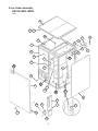
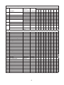
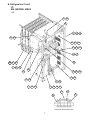
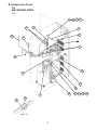
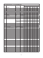
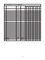
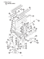
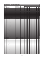
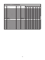
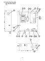
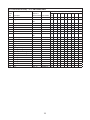
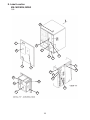
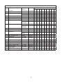
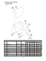
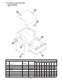
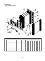
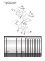
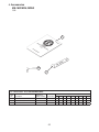
NO.
71245
ISSUED: September 2, 2005
REVISED:
HOSHIZAKI
July xx, 2005
MODULAR CRESCENT CUBER
MODEL
KM-1601MRH
KM-1601MRH3
PARTS LIST
CONTENTS
Auxiliary Codes...................................................................................................................... 3
Note About Ordering Parts .................................................................................................... 3
Material Abbreviations ........................................................................................................... 4
A. Ice Cuber Assembly .......................................................................................................... 5
KM-1601MRH, MRH3 ....................................................................................................... 5
B. Refrigeration Circuit ......................................................................................................... 7
KM-1601MRH, MRH3 ....................................................................................................... 7
C. Water Circuit .................................................................................................................... 11
KM-1601MRH, MRH3 ..................................................................................................... 11
D. Control Box Assembly ..................................................................................................... 14
KM-1601MRH, MRH3 ..................................................................................................... 14
E. Label Location ................................................................................................................. 16
KM-1601MRH, MRH3 ..................................................................................................... 16
F. Capacitor Box Assembly .................................................................................................. 18
KM-1601MRH ................................................................................................................. 18
F. Transformer Box Assembly............................................................................................... 19
KM-1601MRH3 ............................................................................................................... 19
G. Evaporator ...................................................................................................................... 20
KM-1601MRH, MRH3 ..................................................................................................... 20
H. Pump Motor Assembly .................................................................................................... 21
KM-1601MRH, MRH3 ..................................................................................................... 21
J. Accessories...................................................................................................................... 22
KM-1601MRH, MRH3 ..................................................................................................... 22
2
Auxiliary Codes
KM-1601MRH
Q-0
May 2005
KM-1601MRH3
Q-0
May 2005
Note About Ordering Parts
Most assemblies cannot be ordered as complete units; parts in the assemblies generally must
be ordered separately.
3
Material Abbreviations
ALUMINUM
AL
=
Aluminum
COPPER
CU
=
Copper
PLASTIC
ABS
AC
EVA
PA
PC
PE
PES
PETP
PP
PS
PTFE
PUR
PVC
=
=
=
=
=
=
=
=
=
=
=
=
=
Acrylonitrile -butadiene - styrene
Polyacetal
Ethylene vinyl acetate
Polyamide = Nylon
Polycarbonate
Polyethylene
Polyester
Polyethylene terephthalate = Tetlon
Polypropylene
Polystyrene
Polytetrafluoroethylene = Teflon
Polyurethane
Polyvinyl chloride
RUBBER
VN
EPDM
NBR
NR
NP
SI.R
SY.R
EPH
=
=
=
=
=
=
=
=
Vinyl Nitrile
EP rubber
Nitrile butadiene rubber
Natural rubber
Neoprene
Silicone rubber
Synthetic rubber
Epichlorohydrin
STEEL
GS
SS
PS
PAS
=
=
=
=
Galvanized steel
Stainless steel
Plated steel
Primed steel
AUXILIARY CODE
K-0
Designates the year. "K" indicates the year 2000. Years progress or regress in alphabetical order.
"J" is 1999, "L" is 2001, "M" is 2002, and so on. The letters "I" and "O" were skipped.
Designates significant part changes within the same year for this model. Base is 0 and this number
advances for each change.
Example: P-1
"P" indicates 2004.
"1" indicates the first significant part change for 2004.
4
A. Ice Cuber Assembly
KM-1601MRH, MRH3
Q-0
16
15 15a
20
12
4
3
1
5
13
6
D1
D
2
18
E
2a
F1
19
21
21a
MRH
C
B
F
3
MRH
17
14
8
8a
17a
7a
7
9
11
22
10
5
F1
7
Title: A. Ice Cuber Assembly
Model: KM-1601MRH, MRH3
Required Number
Index
No.
B
Description
Material or
Model Number Part Number Q-0
Refrigeration Circuit
KM-1601MRH 1A0242A07
1
KM-1601MRH3 1A0242A08
1
C
Water Circuit
-
1A0094A06
1
D
Cont. Box Assembly
-
2A2527A01
1
D1
T2 Screw
4×8
7P31-0408
3
Label Location
KM-1601MRH 2A2528A03
1
KM-1601MRH3 2A2528A04
1
Capacitor Box Assembly
KM-1601MRH 3A2054A02
1
Transformer Box Assembly
KM-1601MRH3 3A1102A01
1
T2 Screw
KM-1601MRH 7P31-0408
4×8
2
Hex Head Bolt w/Washer (LF)
KM-1601MRH3 7B0130510
5×10
4
1
Evaporator Case
-
1A0602G01
1
2
Cont. Box Cover
GS
3A2386-01
1
2a
T2 Screw
4×8
7P31-0408
2
3
Square Washer
COPPER
433537-02
2
4
Screw – Grounding
BRASS
433304-02
2
5
Bushing
SR-30-1
420472-03
1
6
Bushing
SR-34-2
420472-05
1
7
Junction Box Cover
GS
433410-01
2
7a
T2 Screw
4×8
7P31-0408
2
8
Bulb Holder
-
322815G02
1
8a
FT Screw
4×10, SS
7F32-0410
2
9
Bulb Holder
ABS
328919-01
1
10
Spacer
PE
443545-01
2
E
F
F1
11
Bushing
EPDM
425307-01
1
12
Top Insulation
ABS, PE
322714G01
1
13
Front Insulation
ABS, PE
322711G01
1
14
Side Panel (R)
SS
2A2165G01
1
15
Top Panel
(3A1941A01)
2A2163-01
1
15a
Truss Head Screw
4×8, SS
7C32-0408
1
16
Gasket
(3A1941A01)
427014-04
3
17
Front Panel (A)
SS
2A2164-02
1
17a
Truss Head Screw
4×8, SS
7C32-0408
1
18
Wire Saddle
-
4A0338-03
5
19
Wire Saddle
-
4A0338-02
2
20
Wire Saddle
-
4A0338-01
1
21
Frame (F)
-
324093-01
1
21a
T2 Screw
4×8
7P31-0408
4
22
Gasket
L=762
4A0808L02
1
6
B. Refrigeration Circuit
1/2
KM-1601MRH, MRH3
Q-0
9a
9
8
2a 2b
2
44 44a
23 24 24a
21 22 22a
36 37
G
38
G1 G2
6
6a 42
43
38
15 16 16a
4
12 12a
1
5
1a 1b
3
5a
3a 3b 3c
37
40
41
39
Thermistor Attachment Detail
7
4a
B. Refrigeration Circuit
2/2
KM-1601MRH, MRH3
Q-0
10 10a 11 11a
20
33
19
27
32
31
A
7
30
26
18
25
28
29
17
34
35
Detail "A"
8
13 13a 14 14a
Title: B. Refrigeration Circuit
Model: KM-1601MRH, MRH3
Required Number
Index
No. Description
Material or
Model Number Part Number Q-0
G
Evaporator
-
104442G03
1
G1
Truss Head Screw
4×8, SS
7C31-0408
4
G2
T2 Screw
4×8, SS
7P32-0408
4
1
Frame
GS
222024G02
1
1a
FT Screw
4×8, SS
7F32-0408
4
1b
T2 Screw
4×8
7P31-0408
4
2
Rear Panel
GS
222025G04
1
2a
FT Screw
4×8, SS
7F32-0408
5
2b
T2 Screw
4×8
7P31-0408
5
3
Compressor
KM-1601MRH 4A2334-02
CS18K6E-PFV279
1
KM-1601MRH3 4A2330-02
CS18K6E-TF5279
1
3a
Grommet
-
434922-01
4
3b
Spacer
-
434921-01
4
3c
Bolt
8×45
437889-01
4
4
Receiver Tank
RR MN WP500 440366-01
1
4a
Hex Head Bolt w/Washer (LF)
5×10
7B0130510
3
5
Drier
C-05E84
4A2663-01
1
5a
Nylon Tie
PLWP3H-TL
8911-0301
1
6
Insulation Holder
-
3A0979-01
1
6a
T2 Screw
4×8, SS
7P32-0408
2
7
Expansion Valve
HFE-15NHD-2 4A1482-01
2
8
Clamp
-
4A2338-01
1
9
Hot Gas Valve Bracket
GS
444816-01
1
9a
T2 Screw
4×8
7P31-0408
2
10
Valve Body
70
440352-01
1
10a
Bolt
4×6
440353F01
1
11
Coil – Valve
ABS-25-1HD-2
440353-01
1
11a
Truss Head Screw
4×8
7C31-0408
2
12
Line Valve Bracket
GS
4A1544-01
1
12a
T2 Screw
4×8
7P31-0408
2
13
Valve Body
70
440352-01
1
13a
Bolt
4×6
440353F01
1
14
Coil – Valve
ABS-25-1HD-2
440353-01
1
14a
Truss Head Screw
4×8
7C31-0408
2
15
Pressure Switch
ACB-1UB09
433441-07
1
16
Press. Switch Bracket
GS
434938-01
1
16a
T2 Screw
4×8
7P32-0408
1
17
Copper Tube – Access Valve
COPPER
4A1497G01
1
9
Title: B. Refrigeration Circuit
Model: KM-1601MRH, MRH3
Required Number
Index
No. Description
Material or
Model Number Part Number Q-0
18
Access Valve
TCJ2F20NHDU-1
457729-01
1
19
Strainer
-
441569-02
1
20
Check Valve
SKC30564
4A1373-01
2
21
Coupling
-
434136G01
1
22
Tube Holder – L
GS
438245-01
1
22a
T2 Screw
4×8
7P31-0408
2
23
Coupling
-
433751G01
1
24
Tube Holder – S
GS
438246-01
1
24a
T2 Screw
4×8
7P31-0408
2
25
Copper Tube (A) – High Side
COPPER
2A3136G01
1
26
Copper Tube (B) – High Side
COPPER
447737G01
1
27
Copper Tube (D) – High Side
COPPER
3A1603G01
1
28
Copper Tube (E) – High Side
COPPER
3A3466-01
1
29
Copper Tube (F) – High Side
COPPER
2A3457G01
1
30
Heat Exchanger
COPPER
1A1047G01
1
31
Copper Tube (R) – Low Side
COPPER
222029G02
1
32
Copper Tube (L) – Low Side
COPPER
222030G02
1
33
Copper Tube – Hot Gas
COPPER
3A3491G01
1
34
Holder / Expansion Valve – 3/8 SS
3A0107-01
2
35
Clamp
SS
443461-01
2
36
Insulation Tube
L=40
7762-1020
1
37
Cable Tie
-
7920-0010
12
38
Expansion Valve Cover
PE FOAM
3A0944-01
2
39
Thermistor
-
429006-03
1
40
Holder – Thermistor
COPPER
438247-01
1
41
Insulation – Thermistor
PE FOAM
427441-01
1
42
Insulated Rubber Tube
EPDM
323975G01
1
43
Insulation
PE FOAM
436671-01
1
44
Frame (C)
-
3A0347-01
1
44a
T2 Screw
4×8
7P31-0408
2
10
C. Water Circuit
KM-1601MRH, MRH3
Q-0
19
7
8
16
18
52
50
14
9
53
6
1a
16
6
37
16
46
36
16
32
20
31a
42
13
26
22
23
27
25
28
5
21
16
29
21
15
H1
48
49
47
47a
24
30
48a
41
22a
H
11
12
34a
43
40
34
10
33
35
31
10a
3a
45
17
1
3
44
11
2
4
39
18
51
6
38
49a
Title: C. Water Circuit
Model: KM-1601MRH, MRH3
Required Number
Index
No. Description
Material or
Model Number Part Number Q-0
H
Pump Motor Assembly
(S-0731)
215693A01
1
H1
Hex Head Bolt w/Washer (LF)
SS, 5×12
7B0230512
1
Water Supply Pipe
COPPER
4A0768G01
1
1a
T2 Screw
4×8
7P31-0408
2
2
Rubber Gasket
NR
413854-03
1
3
Water Valve Bracket
GS
321443-01
1
3a
T2 Screw
4×8
7P31-0408
1
4
Water Valve
J248-032
3U0111-02
1
5
Valve Housing – Drain
-
435054-01
1
6
Hose Clamp
SS, 18MM
427443-05
4
7
Spray Tube
PE
1A0260-02
1
8
Spray Tube
PE
1A0260-01
1
9
Spray Guide (A)
PE
208586-01
12
1
10
Plate
SS
3A0133-01
1
10a
T2 Screw
SS, 4×10
7P32-0410
4
11
Cube Guide (A)
SS
214905-01
1
12
Cube Guide (B)
ABS
322644-02
1
13
Thumbscrew
ABS, SS
415949G12
1
14
Vinyl Hose
L=63
7716-2025
2
15
Hose (A)
EPDM
435091-01
1
16
Hose Clamp
SS, 25MM
427443-03
11
17
Holder
PP
322692-01
1
18
Distributor
ABS
432426-01
2
19
Plug
Santoprene
4A0176-01
4
20
Drain Hose
EPDM
435092-01
1
21
Hose Clamp
SS, 27MM
427443-08
2
22
Drain Valve (B)
ABS
3A1170-01
1
22a
T2 Screw
SS, 4×16
7P32-0416
3
23
“O” Ring
1AG35
7611-G035
1
24
Spring
SS
322685-01
1
25
Valve Seat
EPDM
433705-01
1
26
Hose (C)
EPDM
326655-01
1
27
Overflow Cap
ABS
322816-01
1
28
Overflow Pipe
ABS
322691-01
1
29
“O” Ring
-
4A1234-01
1
30
Connector – Float Switch
EPDM
426799-01
1
31
Float Switch
163790
4A0886-02
1
31a
Truss Head Screw
SS, 4×8
7C32-0408
2
32
Connector
ABS
432763-01
1
33
Rubber Ring
TSE2571-5U
439236-01
1
34
Collar
ABS
435269-01
2
34a
T2 Flat Head Screw
SS, 4×16
7P22-0416
2
35
Spring
SS
435825-01
1
36
Vinyl Hose
L=670
7716-2025
1
12
Title: C. Water Circuit
Model: KM-1601MRH, MRH3
Required Number
Index
No. Description
Material or
Model Number Part Number Q-0
37
Vinyl Hose
L=190
7716-2025
1
38
Tee
EPDM
4A0177-01
1
39
Flange
EPDM
439267-01
1
40
Silicone Hose
L=80
7730I3812
2
41
Bypass Hose
EPDM
439265-01
1
42
Corner Insulation (A)
PE FOAM
439376-01
1
43
Corner Insulation (B)
PE FOAM
439392-01
1
44
Male Adaptor
(442137A01)
325826-01
2
45
“O” Ring
7611-P018
2
46
Ball Valve
439293-01
1
47
Valve Holder
GS
3A1178-01
1
47a
FT Screw
4×8
7F31-0408
3
48
Micro Switch
V3L-lll-D8
4A0365-01
1
48a
Tapping Screw
3×14
431415-02
2
49
Handle
JH1352
215383-01
1
49a
T2 Screw
4×8
7P31-0408
1
50
Vinyl Hose
L=58
7716-1519
1
51
Vinyl Hose
L=180
7716-0913
1
52
Water Supply Tube
PE
2A0079-01
1
53
Water Supply Tube
PE
2A0079-02
1
13
D. Control Box Assembly
KM-1601MRH, MRH3
Q-0
2
2a
4
17
4a
15
16
19
18
5
6
13
11
1
14
10
12
3a
3
8
8a
9
7
16
19
14
Title: D. Control Box Assembly
Model: KM-1601MRH, MRH3
Required Number
Index
No. Description
Material or
Model Number Part Number Q-0
1
Cont. Box
GS
2A2524G01
1
2
Magnetic Contactor
A77-309040A- 4A0794-01
226
1
2a
Truss Head Screw
4×12
7C31-0412
2
3
Capacitor
250V, 10MFD
443192-01
1
3a
T2 Screw
4×10
7P31-0410
1
4
Transformer
26D285H
3A0172-01
1
4a
T2 Screw
4×8
7P31-0408
2
5
Controller Board
HOSHIZAKI001
2A1410-01
1
6
Board Support
CBLS37-M
4A0336-03
4
7
Control Label
PES FILM
4A1758-01
1
8
Thermostat
YTB-106B
4A2879-02
1
8a
Truss Head Screw
4×6
7C31-0406
2
9
Toggle Switch
8966K84
443119-01
1
10
3p Plug Housing
3191-03P
412832-06
1
11
2p Plug Housing
3191-02P
412832-07
1
12
3p Receptacle Housing
3191-03R1
412831-06
1
13
2p Receptacle Housing
3191-02R1
412831-07
1
14
Bushing
SB-1093-15
420470-03
1
15
Bushing
SB-1093-13
420470-12
1
16
Bushing
OCB-500
428394-02
2
17
Bushing
OCB-875
428394-04
1
18
Fuse Holder
HTB921
4A0892-01
1
19
Fuse
AGC-10
4A0893-07
2
15
E. Label Location
KM-1601MRH, MRH3
Q-0
16
1
13
5
9
8
2
3
14
7
4
18
10
11
19
17
20
15
14
6
12
16
Title: E. Label Location
Model: KM-1601MRH, MRH3
Required Number
Index
No. Description
Material or
Model Number Part Number Q-0
1
Emblem
ABS
4A0560-01
1
2
Rating Label
KM-1601MRH 2A3460-01
1
KM-1601MRH3 2A3460-02
1
3
Label – Penguin (R)
PETP FILM
4A0526-01
1
4
Maintenance Label
PVC FILM
325975-01
1
5
Caution Label (H)
PVC FILM
439148-01
1
6
Wiring Label
KM-1601MRH 3A3492-01
1
KM-1601MRH3 3A2394-01
PVC FILM
1
7
Nameplate
KM-1601MRH 2A3459-01
1
KM-1601MRH3 2A3459-02
PES FILM
1
8
Caution Label
PVC FILM
436198-01
1
9
Instruction Sheet
PAPER
2A3633-01
1
10
Tag Warning: Electrical
Connection
KM-1601MRH 428430-01
1
KM-1601MRH3 438479-01
PAPER
1
11
Tag – Fan Motor Leads
PAPER
4A1494-01
1
12
Manual Label
PVC FILM
324476-01
1
13
Manual Label – Bin Control
PVC FILM
322846-01
1
14
Label – R404A
PES FILM
4A0960-01
2
15
Label – Control Board
3A2220-01
1
16
Operation Label – Valve
PVC FILM
439541-01
1
17
Caution – Remote Label
PVC FILM
4A1491-01
1
18
Instruction Label
PVC FILM
444575-01
1
19
Label – Alarm
4A3517-01
1
20
Label – Fuse
4A2817-01
1
17
F. Capacitor Box Assembly
KM-1601MRH
Q-0
7a
7
6
5
5a
3
1
4a
2
Title: F. Capacitor Box Assembly
4
Model: KM-1601MRH
Required Number
Index
No. Description
1
Material or
Model Number Part Number Q-0
Capacitor Box
GS
326124-02
1
2
Capacitor – Run
35MFD 370V
3A2005-05
1
3
Capacitor – Starting
1453A0076-01
175MFD250V
1
4
Strap
GS
4A2262-03
1
4a
T2 Screw
4×8
7P31-0408
1
5
Starter
-
4A1107-09
1
5a
T2 Screw
4×8
7P31-0408
1
6
Bushing
SR-34-1
420472-05
1
7
Capacitor Box Cover
GS
326125-01
1
7a
T2 Screw
4×8
7P31-0408
2
18
F. Transformer Box Assembly
KM-1601MRH3
Q-0
2
2a
5
3a
4
6
3
1
Title: F. Transformer Box Assembly
Model: KM-1601MRH3
Required Number
Index
No. Description
Material or
Model Number Part Number Q-0
1
Transformer Box
-
3A1101-01
1
2
Transformer Box Cover
-
438467-01
1
2a
T2 Screw
4×8
7P31-0408
4
3
Transformer
-
4A0817-01
1
3a
Truss Head Screw
4×8
7C31-0408
4
4
Slide Switch
-
4A1477-01
1
5
Bushing
SR-30-1
420472-03
1
6
Manual Label – Tap Switch
PVC FILM
439423-01
1
19
G. Evaporator
KM-1601MRH, MRH3
Q-0
1
8
4
5
Pop-Rivet
2
1
8
6
Pop-Rivet
3
6
7
Title: G. Evaporator Model: KM-1601MRH, MRH3
Required Number
Index
No. Description
Material or
Model Number Part Number
Q-0
1
Evaporator
S-0428
103317G01
4
2
Evap. Bracket (A)
SS
322700-01
1
3
End Plate (A)
ABS
322842-01
1
4
Evap. Bracket (B)
SS
322701-01
1
5
End Plate (B)
ABS
322843-01
1
6
Evap. Bracket (C)
GS
4A0659-01
2
7
Copper Tube
COPPER
434320-01
2
8
Frame – Evap.
GS
435062-01
2
20
H. Pump Motor Assembly
KM-1601MRH, MRH3
Q-0
2a
2b
1
2c
2d
2e
8a
4
2
3
7
5
8b
6
8
Title: H. Pump Motor Assembly Model: KM-1601MRH, MRH3
Required Number
Index
No. Description
Material or
Model Number Part Number Q-0
1
Pump Motor
M91A60SP201
2U0106-01
1
2
Pump Flange
PC
215662-01
1
2a
Hexagon Bolt
SS, 6×40
7B02-0640
4
2b
Tooth Washer
SS, M6
7R22-0600
1
2c
Flat Washer
SS, M6
7F22-0600
4
2d
Split Lock Washer
SS, M6
7L22-0600
4
2e
Nut
SS, M6
7N12-0600
4
3
Pump Motor Bracket
SS
435057-01
1
4
Mechanical Seal
H5-PN, 8MM
428545-01
1
5
Packing
EPDM
428547-01
1
6
Impeller
ABS
428548-01
1
7
Pin
SS
4A0648-01
1
8
Pump Housing
ABS
212636-01
1
8a
Hexagon Bolt
SS, 4×30
7B02-0430
4
8b
Flange Nut
SS, M4
7J02-0400
4
21
J. Accessories
KM-1601MRH, MRH3
Q-0
1
2a
2
Title: J. Accessories Model: KM-1601MRH, MRH3
Index
No. Description
1
Instruction Manual
2
2a
Material or
Model Number Part Number Q-0
PAPER
91A1FE10A
1
Universal Brace
GS
4A0363-01
2
Hex Head Bolt
SS, 5×12
7B02-0512
2
22
Required Number