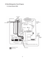
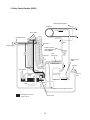
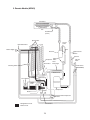
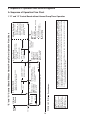
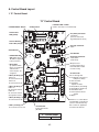
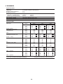
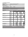
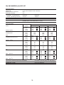
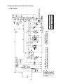
1
Hoshizaki
Hoshizaki America, Inc.
Modular Crescent Cuber
Models
KM-320MAH, MWH
KM-515MAH, MWH, MRH
KM-600MAH
KM-650MAH, MWH, MRH
KM-901MAH, MWH, MRH/3
KM-1340MAH, MWH, MRH
KM-1601MRH/3
“A Superior Degree
of Reliability”
SERVICE MANUAL
www.hoshizaki.com
Number: 73196
Issued: 4-29-2013
Revised: 9-22-2014
WARNING
Only qualified service technicians should install and service the appliance. To
obtain the name and phone number of your local Hoshizaki Certified Service
Representative, visit www.hoshizaki.com. No service should be undertaken until
the technician has thoroughly read this Service Manual. Failure to service and
maintain the appliance in accordance with this manual will adversely affect safety,
performance, component life, and warranty coverage. Proper installation is the
responsibility of the installer. Product failure or property damage due to improper
installation is not covered under warranty.
Hoshizaki provides this manual primarily to assist qualified service technicians in the
service of the appliance.
Should the reader have any questions or concerns which have not been satisfactorily
addressed, please call, send an e-mail message, or write to the Hoshizaki Technical
Support Department for assistance.
Phone: 1-800-233-1940; (770) 487-2331
Fax: 1-800-843-1056; (770) 487-3360
E-mail: [email protected]
HOSHIZAKI AMERICA, INC.
618 Highway 74 South
Peachtree City, GA 30269
Attn: Hoshizaki Technical Support Department
Web Site: www.hoshizaki.com
NOTE: To expedite assistance, all correspondence/communication MUST include the
following information:
• Model Number
• Serial Number
• Complete and detailed explanation of the problem.
2
IMPORTANT
This manual should be read carefully before the appliance is serviced. Read
the warnings and guidelines contained in this manual carefully as they provide
essential information for the continued safe use, service, and maintenance of the
appliance. Retain this manual for any further reference that may be necessary.
CONTENTS
Important Safety Information.................................................................................................. 6
I. Construction and Water/Refrigeration Circuit Diagram........................................................ 8
A. Construction................................................................................................................... 8
1. Air-Cooled Models (MAH)......................................................................................... 8
2. Water-Cooled Models (MWH)................................................................................... 9
3. Remote Models (MRH/3)........................................................................................ 10
B. Water/Refrigeration Circuit Diagram..............................................................................11
1. Air-Cooled Models (MAH)........................................................................................11
2. Water-Cooled Models (MWH)................................................................................. 12
3. Remote Models (MRH/3)........................................................................................ 13
II. Sequence of Operation and Service Diagnosis................................................................ 14
A. Sequence of Operation Flow Chart.............................................................................. 14
1. "E" and "G" Control Board without Harvest Pump Timer Operation........................ 14
2. "G" Control Board with Harvest Pump Timer Operation ........................................ 16
B. Service Diagnosis........................................................................................................ 17
1. "E" and "G" Control Board without Harvest Pump Timer Diagnosis........................ 18
2. "G" Control Board with Harvest Pump Timer Diagnosis......................................... 24
C. Control Board Check.................................................................................................... 30
D. Bin Control Check........................................................................................................ 31
1. Thermostatic Bin Control Check ............................................................................. 31
2. Mechanical Bin Control Check and Cleaning ........................................................ 32
E. Float Switch Check and Cleaning................................................................................ 34
1. Float Switch Check................................................................................................. 34
2. Float Switch Cleaning............................................................................................. 35
F. Thermistor Check.......................................................................................................... 36
G. Diagnostic Tables......................................................................................................... 37
III. Controls and Adjustments................................................................................................ 41
A. Control Board Layout................................................................................................... 42
1. "E" Control Board ................................................................................................... 42
2. "G" Control Board .................................................................................................. 43
B. LED Lights and Audible Alarm Safeties........................................................................ 44
1. "E" Control Board ................................................................................................... 44
2. "G" Control Board .................................................................................................. 45
C. Settings and Adjustments............................................................................................. 46
1. Default Dip Switch Settings..................................................................................... 46
a) "E" and "G" Control Board without Harvest Pump Timer Operation................... 46
b) "G" Control Board with Harvest Pump Timer Operation..................................... 46
2. Harvest Timer (S4 dip switch 1 & 2)....................................................................... 47
3. Pump-Out Timer (S4 dip switch 3 & 4)................................................................... 47
4. Pump-Out Frequency Control (S4 dip switch 5 & 6)............................................... 48
3
5. Bin Control Selector or Harvest Pump Timer Operation (S4 dip switch 7).............. 48
6. Factory Use (S4 dip switch 8)................................................................................. 49
7. Freeze Timer (S4 dip switch 9 & 10)........................................................................ 49
8. Float Switch Selector (S5 dip switch 1): "G" Control Board.................................... 50
9. Refill Counter (S5 dip switch 2 through 5): "G" Control Board................................ 50
D. Control Switch.............................................................................................................. 50
IV. Refrigeration Circuit and Component Service Information.............................................. 51
A. Refrigeration Circuit Service Information..................................................................... 51
B. Component Service Information................................................................................... 54
C. Water Regulating Valve Adjustment (water-cooled model)........................................... 54
V. Maintenance..................................................................................................................... 55
VI. Preparing the Appliance for Periods of Non-Use............................................................. 56
VII. Disposal.......................................................................................................................... 58
VIII. Technical Information..................................................................................................... 59
A. Specification and Performance Data Sheets................................................................ 59
1. KM-320MAH........................................................................................................... 59
2. KM-320MWH.......................................................................................................... 60
3. KM-515MAH........................................................................................................... 61
4. KM-515MWH.......................................................................................................... 62
5. KM-515MRH with URC-5F..................................................................................... 63
6. KM-600MAH........................................................................................................... 64
7. KM-650MAH............................................................................................................ 65
8. KM-650MWH.......................................................................................................... 66
9. KM-650MRH with URC-5F..................................................................................... 67
10. KM-901MAH......................................................................................................... 68
11. KM-901MWH......................................................................................................... 69
12. KM-901MRH with URC-9F.................................................................................... 70
13. KM-901MRH3 with URC-9F.................................................................................. 71
14. KM-1340MAH....................................................................................................... 72
15. KM-1340MWH...................................................................................................... 73
16. KM-1340MRH with URC-14F.................................................................................74
17a. KM-1601MRH with URC-21F.............................................................................. 75
17b. KM-1601MRH with URC-22F.............................................................................. 76
18a. KM-1601MRH3 with URC-21F............................................................................ 77
18b. KM-1601MRH3 with URC-22F............................................................................ 78
4
C. Wiring Diagrams .......................................................................................................... 79
1. Diagrams Without Harvest Pump Timer Relays...................................................... 79
a) KM-320M_H, KM-515M_H, KM-600MAH......................................................... 79
b) KM-650MAH (V-1 and earlier), KM-650MWH (V-1 and earlier),
KM-901MAH (B-0 and earlier), KM-901MWH (C-0 and earlier)........................ 80
c) KM-650MRH (V-1 and earlier), KM-901MRH (C-0 and earlier)......................... 81
d) KM-901MWH (D-1 and later), KM-901MRH (C-1 and later).............................. 82
e) KM-1340MAH, KM-1340MWH.......................................................................... 83
f) KM-1340MRH ................................................................................................... 84
g) KM-1601MRH................................................................................................... 85
h) KM-901MRH3, KM-1601MRH3......................................................................... 86
2. Diagrams With Harvest Pump Timer Relays........................................................... 87
a) KM-515MAH..................................................................................................... 87
b) KM-650MAH (V-2 to C-2), KM-650MWH (V-2 to C-2),
KM-901MAH (B-1 to C-2).................................................................................. 88
c) KM-650MAH (D-1 and later), KM-650MWH (D-1 and later),
KM-901MAH (D-1 and later).............................................................................. 89
d) KM-650MRH (V-2 to C-1).................................................................................. 90
e) KM-650MRH (C-2 and later)............................................................................. 91
5
Important Safety Information
Throughout this manual, notices appear to bring your attention to situations which could
result in death, serious injury, damage to the appliance, or damage to property.
WARNING Indicates a hazardous situation which could result in death or
serious injury.
NOTICE
Indicates a situation which could result in damage to the
appliance or property.
IMPORTANT
Indicates important information about the use and care of the
appliance.
WARNING
The appliance should be destined only to the use for which it has been expressly
conceived. Any other use should be considered improper and therefore dangerous.
The manufacturer cannot be held responsible for injury or damage resulting from
improper, incorrect, and unreasonable use. Failure to service and maintain the
appliance in accordance with this manual will adversely affect safety, performance,
component life, and warranty coverage and may result in costly water damage.
To reduce the risk of death, electric shock, serious injury, or fire, follow basic
precautions including the following:
• Only qualified service technicians should install and service this appliance.
• The appliance must be installed in accordance with applicable national, state, and
local codes and regulations.
• Electrical connection must be hard-wired and must meet national, state, and local
electrical code requirements. Failure to meet these code requirements could result
in death, electric shock, serious injury, fire, or severe damage to equipment.
• The icemaker requires an independent power supply of proper capacity. See the
nameplate for electrical specifications. Failure to use an independent power supply
of proper capacity can result in a tripped breaker, blown fuses, damage to existing
wiring, or component failure. This could lead to heat generation or fire.
• THE ICEMAKER MUST BE GROUNDED. Failure to properly ground the icemaker
could result in death or serious injury.
• Move the control switch to the "OFF" position and turn off the power supply before
servicing. Lockout/Tagout to prevent the power supply from being turned back on
inadvertently.
• To reduce the risk of electric shock, do not touch the control switch with damp
hands.
• Do not make any alterations to the unit. Alterations could result in electric shock,
injury, fire, or damage to the unit.
• The appliance is not intended for use by persons (including children) with reduced
physical, sensory, or mental capabilities, or lack of experience and knowledge,
unless they have been given supervision or instruction concerning use of the
appliance by a person responsible for their safety.
6
WARNING, continued
• Children should be properly supervised around this appliance.
• Do not climb, stand, or hang on the appliance or allow children or animals to do so.
Serious injury could occur or the appliance could be damaged.
• Do not use combustible spray or place volatile or flammable substances near the
appliance. They might catch fire.
• Keep the area around the appliance clean. Dirt, dust, or insects in the appliance
could cause harm to individuals or damage to the appliance.
Additional Warning for Remote Models
• THE REMOTE CONDENSER UNIT MUST BE GROUNDED. The power supply and
ground connection to the remote condenser unit are supplied from the icemaker.
Failure to properly ground the remote condenser unit could result in death or
serious injury.
• Move the icemaker control switch to the "OFF" position and turn off the power
supply to the icemaker before servicing the remote condenser unit.
Lockout/Tagout to prevent the power supply from being turned back on
inadvertently.
NOTICE
• Follow the instructions in this manual carefully to reduce the risk of costly water
damage.
• In areas where water damage is a concern, install in a contained area with a floor
drain.
• Install the appliance in a location that stays above freezing. Normal operating
ambient temperature must be within 45°F to 100°F (7°C to 38°C).
• Do not leave the icemaker on during extended periods of non-use, extended
absences, or in sub-freezing temperatures. To properly prepare the icemaker for
these occasions, follow the instructions in "VI. Preparing the Appliance for Periods
of Non-Use."
• Do not place objects on top of the appliance.
• The dispenser unit/ice storage bin is for ice use only. Do not store anything else in
the dispenser unit/ice storage bin.
7
I. Construction and Water/Refrigeration Circuit Diagram
A. Construction
1. Air-Cooled Models (MAH)
Thermostatic
Expansion Valve
Water Supply Inlet
Spray Tubes
Hot Gas Valve
Inlet Water Valve
Thermostatic
Bin Control
Condenser
Cleaning Valve
Fan Motor
Control Switch
High-Pressure
Switch
Drier
Float Switch
Water Pump
Liquid Line Valve
KM-515MAH
Control Box
Compressor
Mechanical Bin Control and Bracket
Thermostatic Bin Control
Bracket & Bulb Holder
Model Shown: KM-515MAH
8
2. Water-Cooled Models (MWH)
Thermostatic
Expansion Valve
Water Supply Inlet
Spray Tubes
Hot Gas Valve
Inlet Water Valve
High-Pressure Switch
Water Regulating
Valve
Thermostatic
Bin Control
Condenser
Cleaning Valve
Control Box
Control Switch
Liquid Line Valve
KM-320MWH and
KM-515MWH
Float Switch
Drier
Water Pump
Compressor
Mechanical Bin Control and Bracket
Thermostatic Bin Control
Bracket & Bulb Holder
Model Shown: KM-515MWH
9
3. Remote Models (MRH/3)
Thermostatic
Expansion Valves
Spray Tubes
Water Supply Inlet
Inlet Water Valve
Hot Gas Valve
Cleaning Valve
Junction Boxes
Control Switch
Control Box
Thermostatic
Bin Control
Receiver Tank
Float Switch
Water Pump
Drier
Compressor
Liquid Line Valve
Thermostatic Bin Control
Bracket & Bulb Holder
Mechanical Bin Control and Bracket
Model Shown: KM-901MRH
10
B. Water/Refrigeration Circuit Diagram
1. Air-Cooled Models (MAH)
Spray Tubes
Condenser
Inlet Water Valve
Drier
Evaporator
Water Supply
Fan
High-Pressure
Switch
Liquid Line Valve
(KM-515MAH)
Thermistor
Heat
Exchanger
Suction Line
Strainer
Water Pump
Float Switch
Hot Gas
Valve
Water
Tank
Compressor Discharge Line
Drain
Freeze
Pump Out
Thermostatic Expansion Valve
Refrigeration Circuit
Check Valve
Water Circuit
11
2. Water-Cooled Models (MWH)
Water Regulating Valve
Condenser
Spray Tubes
Inlet Water Valve
Drier
Evaporator
Water Supply
Liquid Line Valve
(KM-320MWH and
KM-515MWH)
Thermistor
Heat
Exchanger
High-Pressure
Switch
Suction Line
Strainer
Water Pump
Float Switch
Hot Gas
Valve
Water
Tank
Compressor
Drain
Freeze
Discharge Line
Pump Out
Thermostatic Expansion Valve
Refrigeration Circuit
Check Valve
Water Circuit
12
3. Remote Models (MRH/3)
Condenser
Fan
Headmaster
(C.P.R.)
Spray Tubes
Access
Valve
Inlet Water Valve
Drier
Water Supply
High-Pressure
Switch
Receiver
Strainer
Liquid Line
Evaporator Valve
Heat
Exchanger
Thermistor
Hot Gas
Valve
Check Valves
(KM-901MRH)
Cleaning Valve
Suction Line
Water Pump
Float Switch
Water
Tank
Discharge Line
Drain
Freeze
Pump-Out
Compressor
Thermostatic Expansion
Valve
Refrigeration Circuit
Check Valve
Water Circuit
13
Comp energized
FMR energized
HGV energized
WV energized
FS closed
Thermistor in
control
14
Legend:
Comp–compressor
FM–fan motor
FMR–fan motor-remote
FS–float switch
HGV–hot gas valve
LLV–liquid line valve
PM–pump motor
WV–inlet water valve
FS opens or
freeze timer
terminates
FS in control
Comp continues
FMR continues
HGV energized
WV energized (KM-320M_H S4 dip
switch 3 & 4)
PM de-energizes for 2 sec.,
then reverses for 10/20 sec.
FM de-energized
LLV de-energized
• Factory set for every
10th cycle
(except KM‑515M_H)
(S4 dip switch 5 & 6)
• Pump motor stops for
2 sec., then reverses
for 10/20 sec. (S4 dip
switch 3 & 4)
4. Pump-Out Cycle
The "WASH" position on the control switch is used when cleaning and sanitizing the icemaker. When in the "WASH" position,
power is supplied to the pump motor. With the cleaning valve closed, the cleaner and sanitizer flow over the outside of the
evaporator plate assembly. With the cleaning valve open, the cleaner and sanitizer flow over both the outside and the inside
of the evaporator plate assembly.
Note: Close the cleaning valve after cleaning and sanitizing are complete, otherwise the icemaker will not restart when the control switch is placed in the "ICE" position.
Comp continues
FMR continues
FM energized
LLV energized
PM energized
HGV de-energized
WV de-energized
FS closed
5-min. minimum
freeze timer in
control
• Minimum freeze time: 5 min.
• Maximum freeze time: freeze
timer setting
(S4 dip switch 9 & 10)
3. Freeze Cycle
Components Energized when the Control Switch is in the "WASH" Position
See next page.
FS open
Thermistor temperature
reaches 48°F (9°C) (3.9 kΩ
or less). Harvest timer starts
(1 to 3 min.).
FS check
1 to 3-min. harvest
timer in control
(S4 dip switch 1 & 2)
• Maximum inlet water valve time: 6 min.
• Maximum harvest time: 20 min.
2. Harvest Cycle
If FS is open, Comp stops and cycle returns to 1-min. fill.
FS open
WV energized
FS check
1. 1-Minute
Fill Cycle
Shutdown and Restart
Startup
Cycle
Steps
"E" and "G" Control Board Without Harvest Pump Timer Operation Flow Chart
II. Sequence of Operation and Service Diagnosis
A. Sequence of Operation Flow Chart
1. "E" and "G" Control Board without Harvest Pump Timer Operation
15
2. Icemaker Off
TBC closed
No ice touching
TBC bulb.
Icemaker starts at
"1. 1-Minute Fill Cycle."
3. Ice Level Lowered
Legend:
MBC–mechanical bin control
TBC–themostatic bin control
MBC Operation
Shutdown
and Restart
MBC open (MBC actuator paddle engaged)
Green "BC CLOSED" LED off
Yellow "BC OPEN" LED on
All components de-energized.
Yellow "BC OPEN" LED continues. All
components de‑energized.
Shutdown Delay:
• Fill Cycle–15 sec. after activation.
• Harvest Cycle–At the end of the harvest cycle, or up to 15 sec. into the freeze cycle if activated at the end of the harvest cycle.
• Freeze Cycle–15 sec. after activation if activated at least 15 sec. before the 5-min. short cycle protection timer terminates.
Otherwise, at the end of the next harvest cycle.
1. Bin Full
2. Icemaker Off
To 1. 1-Minute Fill Cycle
Mechanical Bin Control Shutdown Sequence Flow Chart
TBC open
All components
de-energized
All components Within 10 sec.
after ice contacts de-energized.
TBC bulb, icemaker shuts
down.
1. Bin Full
Ice contacts TBC bulb
TBC
Operation
Shutdown
and Restart
Thermostatic Bin Control Shutdown Sequence Flow Chart
MBC closed
(MBC actuator paddle disengaged)
Green "BC CLOSED" LED on
Yellow "BC OPEN" LED off
To 1. 1-Minute Fill Cycle
Icemaker starts at
"1. 1-Minute Fill Cycle."
3. Ice Level Lowered
"E" and "G" Control Board Without Harvest Pump Timer Operation Flow Chart, Continued
Comp energized
FMR energized
HGV energized
WV energized
FS closed
Thermistor in
control
Thermistor temperature reaches
48°F (9°C) (3.9 kΩ or less). Harvest
timer starts (1 to 3 min.).
FS open
16
Yellow "BC OPEN" LED continues. All
components de‑energized.
To 1 above
MBC closed
(MBC actuator paddle disengaged)
Green "BC CLOSED" LED on
Yellow "BC OPEN" LED off
Icemaker starts at
"1. 1-Minute Fill Cycle."
3. Ice Level Lowered
Comp continues
FMR continues
HGV energized
PM de-energizes for 2 sec.,
then reverses for 10/20 sec.
FM de-energized
LLV de-energized
• Factory set for every
10th cycle
(except KM-515M_H)
(S4 dip switch 5 & 6)
• Pump motor stops for
2 sec., then reverses
for 10/20 sec.
(S4 dip switch 3 & 4)
4. Pump-Out Cycle
The "WASH" position on the control switch is used when cleaning and sanitizing the icemaker. When in the "WASH" position, power is
supplied to the pump motor. With the cleaning valve closed, the cleaner and sanitizer flow over the outside of the evaporator plate assembly.
With the cleaning valve open, the cleaner and sanitizer flow over both the outside and the inside of the evaporator plate assembly.
Note: Close the cleaning valve after cleaning and sanitizing are complete, otherwise the icemaker will not restart when the control switch is placed in the "ICE" position.
Components Energized when the Control Switch is in the "WASH" Position
MBC open (MBC actuator paddle engaged)
Green "BC CLOSED" LED off
Yellow "BC OPEN" LED on
Legend:
Comp–compressor
FM–fan motor
FMR–fan motor-remote
FS–float switch
HGV–hot gas valve
LLV–liquid line valve
MBC–mechanical bin control
PM–pump motor
WV–inlet water valve
MBC Operation
All components de-energized.
FS opens or
freeze timer
terminates
FS in control
2. Icemaker Off
Comp continues
FMR continues
FM energized
LLV energized
PM energized
HGV de-energized
FS closed
5-min. minimum
freeze timer in
control
• Minimum freeze time: 5 min.
• Maximum freeze time: freeze timer
setting (S4 dip switch 9 & 10)
3. Freeze Cycle
Shutdown Delay:
• Fill Cycle–15 sec. after activation.
• Harvest Cycle–At the end of the harvest cycle, or up to 15 sec. into the freeze cycle if activated at the end of the harvest cycle.
• Freeze Cycle–15 sec. after activation if activated at least 15 sec. before the 5-min. short cycle protection timer terminates.
Otherwise, at the end of the next harvest cycle.
1. Bin Full
PM energized
WV de-energized
FS check
50 sec.
Harvest Pump
Timer
1 to 3-min. harvest timer in
control (S4 dip switch 1 & 2)
• Maximum inlet water valve time: 6 min. or the length of harvest minus 50 sec. (S4 dip switch 7), whichever is shorter.
• Maximum harvest time: 20 min.
2. Harvest Cycle
If FS is open, Comp stops and cycle returns to 1-min. fill.
FS open
WV energized
FS check
1. 1-Minute
Fill Cycle
Shutdown
and Restart
Startup
Cycle
Steps
"G" Control Board With Harvest Pump Timer Operation Sequence Flow Chart
2. "G" Control Board with Harvest Pump Timer Operation
B. Service Diagnosis
WARNING
• The appliance should be diagnosed and repaired only by qualified service
personnel to reduce the risk of death, electric shock, serious injury, or fire.
• Risk of electric shock. Control switch in "OFF" position does not de‑energize all
loads Use extreme caution and exercise safe electrical practices.
• Moving parts (e.g., fan blade) can crush and cut. Keep hands clear.
• Before servicing the appliance, move the control switch to the "OFF" position and
turn off the power supply.
• CHOKING HAZARD: Ensure all components, fasteners, and thumbscrews are
securely in place after the appliance is serviced. Make sure that none have fallen
into the dispenser unit/ice storage bin.
• Make sure all food zones in the appliance and dispenser unit/ice storage bin are
clean after service.
The diagnostic procedure is a sequence check that allows you to diagnose the electrical
system and components. Before proceeding, check for correct installation, proper voltage
per nameplate, and adequate water supply. Check CB using the steps in "II.C. Control
Board Check." Check dip switch settings to assure that S4 dip switch 3, 4, 7, 8, 9, 10 and
S5 dip switch 1 through 5 ("G" CB) are in the factory default position. S4 dip switch 1, 2,
5, 6 are cleaning adjustments and the settings are flexible. For factory default settings,
see "III.C.1. Default Dip Switch Settings."
Note: • When checking high voltage (115VAC), always choose a white (W) neutral wire to
establish a good neutral connection.
• On 208-230/60/1 models with main transformer and 208-230/60/3 models, the
appliance neutral (W) is provided through the main transformer. To confirm
a good neutral, check for 60VAC from white (W) neutral to ground (GND).
If 60VAC is present, neutral is good. If 60VAC is not present, check 208-230VAC
main power supply to main transformer. If 208-230VAC is present, check main
transformer continuity.
• When checking voltage from the CB K1 connector (10 pin connector), pull
CB K1 connector out slightly to allow room for multimeter test leads contact.
1) Turn off the power supply, then access the control box. Move the control switch to the
"OFF" position. Clear any ice from BC.
2) Check that the 115VAC 10A fuse is good.
17
1. "E" and "G" Control Board without Harvest Pump Timer Diagnosis
3) Power On: Turn on the power supply, then move the control switch to the "ICE" position.
A 5‑sec. delay occurs.
• "E" Control Board: CB red "POWER OK" LED turns on.
• "G" Control Board: CB red "POWER OK" LED and green "BC CLOSED" LED turn on.
Note: • CB red "POWER" LED remains on unless the 10.5VAC power supply is
interrupted (K2 connector).
• Check CB using the steps in "II.C. Control Board Check."
• "G" CB with Thermostatic Bin Control: If yellow "BC OPEN" LED is on, check that
CB red K4 connector has jumper 4A4883G01 properly connected.
• "G" CB with Mechanical Bin Control: If yellow "BC OPEN" LED is on (indicating a
full bin), check MBC. See "II.D.2. Mechanical Bin Control Check and Cleaning."
a) Power On Diagnosis: If CB red "POWER OK" LED is off, confirm closed TBC and
10A fuse is good. If TBC is open, remove ice from bulb and warm bulb in hand.
If TBC does not close, replace TBC. See "II.D.1. Thermostatic Bin Control Check."
Check for 115VAC at control switch #1 (BR) to neutral (W) then at control switch
#2 (P) to neutral (W). If 115VAC is present on #1 (BR) and not on #2 (P), replace
control switch. If 115VAC is present on control switch #2 (P), check for 115VAC at
HPS (P) to neutral (W) then HPS (BK) to neutral (W). If 115VAC is present at HPS
(P) and not at HPS (BK), HPS is open. See HPS Diagnosis below. If 115VAC is
present at HPS (BK), check for 10.5VAC at CB K2 #1 red wire to CB K2 #2 red wire.
If 10.5VAC is not present, check that the cleaning valve is closed and the interlock
switch is closed. Next, check CT continuity. If open replace CT.
b) HPS Diagnosis: Check that the condenser coil is not clogged or restricted. Let
refrigeration circuit pressures equalize. If HPS does not reset and pressures are
equalized, replace HPS. If pressures are not equalized, reclaim refrigerant and
diagnose refrigeration circuit restriction. Check that there are no restrictions in the
refrigeration circuit.
Harvest Cycle: HGV, strainer, or check valve.
Freeze Cycle: FM, FMR, TXV, HM, LLV, strainer, check valve, drier, and damaged line
set or fitting. Also confirm WRV opens in freeze cycle.
Confirm that the location meets installation requirements:
• The icemaker is not intended for outdoor use. Normal operating ambient temperature
should be within 45°F to 100°F (7°C to 38°C).
• Allow 6" (15 cm) clearance at rear, sides, and top for proper air circulation and ease
of maintenance and/or service should they be required.
• The appliance should not be located in a corrosive environment.
18
4) 1-Minute Fill Cycle – LED 4 is on. WV energizes. After 1 min., CB checks for a closed
FS. If FS is closed, harvest cycle begins. If harvest cycle begins (Comp, HGV, and FMR
energize), continue to step 5. If FS is open, WV remains energized through additional
1‑min. fill cycles until water enters the water tank and FS closes (low water safety
protection during initial start up and at the end of each harvest). Diagnosis: Check
that water enters the water tank. If not, check that the water supply line shut‑off valve
is open and screens or external filters are clear. Check for 115VAC at CB K1 #6 (O)
to neutral (W). If 115VAC is not present, replace CB. If 115VAC is present, and WV
does not energize, check for 115VAC at WV. If 115VAC is present, check coil continuity.
If open, replace WV. If the water tank fills, but the appliance fails to start harvest (Comp
energized), check for open FS. See "II.E. Float Switch Check and Cleaning." If FS is
closed and CB fails to start the harvest cycle after 1 min., replace CB.
5) Initial Harvest Cycle – LEDs 1, 4, and 2 are on. WV continues. Comp, FMR, and
HGV energize. CB monitors the warming of the evaporator via the thermistor located
on the suction line. When the thermistor reaches 48°F (9°C), CB reads 3.9 kΩ from the
thermistor and turns harvest termination over to the harvest timer (S4 dip switch 1 & 2).
The harvest timer has settings of 60, 90, 120, and 180 sec. The pump‑out timer (S4 dip
switch 3 & 4) acts in place of the harvest timer during cycles with a pump‑out (S4 dip
switch 5 & 6). WV remains energized during harvest for a maximum of 6 min. or the
length of harvest, whichever is shorter.
a) Comp Diagnosis: Check that evaporator is warming. If not, confirm that Comp
energizes. If not, check for 115VAC at CB K1 #1 or #9 (V) to neutral (W). If 115VAC is
not present, check for 115VAC at CB K1 #7 or #10 (BR) to neutral (W). If 115VAC is
present at #7 or #10 (BR) and not at #1 or #9 (V), replace CB. If 115VAC is present,
check for 115VAC at CR or MC solenoid. If 115VAC is present, confirm contacts are
closed. If not, replace CR or MC. If CR or MC contacts are closed, check Comp
external overload, Comp start and run capacitors, Comp start relay, and Comp motor
winding.
b) HGV Diagnosis: If Comp is energized and evaporator is not warming, check that
HGV energizes and opens. Check for 115VAC at CB K1 #2 (P) to neutral (W).
If 115VAC is not present, replace CB. If 115VAC is present, check for 115VAC at HGV
coil and check HGV coil continuity. Replace as needed.
c) LLV Diagnosis: Confirm that LLV is de-energized and closed (not bypassing).
If energized, replace CB. If de-energized and bypassing, replace LLV.
d) WRV Diagnosis: Confirm WRV is not leaking by.
19
e) Initial Harvest Cycle Termination Diagnosis: When the thermistor reaches 48°F
(9°C), CB reads 3.9 kΩ from the thermistor and turns harvest termination over to
the harvest timer (S4 dip switch 1 & 2). Check discharge line temperature. For a
thermistor check, see "II.F. Thermistor Check." If 1-min. fill cycle starts after harvest
timer terminates, check that FS is clean and operating properly, see "II.E. Float
Switch Check and Cleaning." If FS is closed, CB proceeds to the next cycle. If not,
replace CB.
Note: The minimum total time allowed by CB for a complete harvest cycle is 2 min.
Maximum harvest time allowed is 20 min.
NOTICE! On models with "G" control board and no harvest pump timer relays,
S4 dip switch 7 must remain off. Otherwise, PM energizes in reverse direction the
last 50 seconds of harvest and empties water from water tank.
6) Freeze Cycle – LED 1 is on. Comp and FMR continue. PM, FM, and LLV energize.
WV and HGV de‑energize. Appliance is held in freeze by a 5-min. short cycle protection
timer. After 5-min. timer terminates and FS opens, freeze cycle terminates.
a) Freeze Cycle Diagnosis: Confirm Comp and FMR continue. Confirm that
PM, FM, and LLV energize. Confirm WRV opens. Next, confirm WV and HGV
de‑energize. During the first 5 min. of freeze, confirm evaporator is cooling. If not,
confirm WV de-energized (not leaking by), HGV de-energized (not bypassing),
LLV and FM energize, TXV and HM operate correctly, WRV opens, Comp is
efficient, and refrigerant charge is correct. See "VIII.A. Specification Sheet" and
"VIII.B. Performance Data."
b) Comp and FMR Diagnosis: If Comp and FMR de-energize once freeze begins,
check that appliance has not shut off on HPS ("POWER OK" LED off). If so, check
"3)b) HPS Diagnosis" above. If "POWER OK" LED is on, check for 115VAC at CB
K1 #1 (V) or #9 (V) to neutral (W). If 115VAC is not present and LED 1 is on, replace
CB. If 115VAC is present, check for 115VAC at CR or MC coil. If 115VAC is present,
check CR or MC coil and contact continuity. Replace as needed. If CR or MC is ok,
check Comp external overload, start relay, and start and run capacitors. Next, check
Comp motor winding continuity. If Comp is energized but evaporator is not cooling,
check for an inefficient Comp. See "VIII.B. Performance Data." If Comp is energized
but FMR is not, check for 115VAC at the FMR junction box. If 115VAC is not present,
check icemaker wiring connections. If 115VAC is present, check for voltage at
condenser unit. If 115VAC is not present, check field wiring connections. If 115VAC is
present, check FMR capacitor, motor winding, and fan blade for binding.
c) WV and HGV Diagnosis: If WV is energized, check for 115VAC at CB K1 #6 (O) to
neutral (W). If 115VAC is present after PM energizes, replace CB. If 115VAC is not
present, replace WV (bypassing). If HGV did not de-energize, check for 115VAC at
CB K1 #2 (P) to neutral (W). If 115VAC is present after PM energizes, replace CB.
If 115VAC is not present, replace HGV (bypassing).
20
d) PM Diagnosis: Confirm water is flowing over evaporator from PM and not WV. If PM
de-energizes once freeze begins, check for 115VAC at CB K1 #4 (R) to neutral (W).
If 115VAC is not present, replace CB. If 115VAC is present and PM is de-energized,
check for 115VAC at control switch #5 (R) to neutral (W). If 115VAC is present at CB
K1 #4 (R) and not at control switch #5 (R), check control switch continuity between
#5 (R) and #4 (R). Replace as needed. If 115VAC is present at control switch #5 (R)
to neutral (W), check PM capacitor and motor winding continuity.
e) FM and LLV Diagnosis: If FM or LLV does not energize, check for 115VAC at CB
K1 #3 (BK) to neutral (W). If 115VAC is not present, replace CB. If 115VAC is present:
For FM, check capacitor, motor winding, and blade for binding.
For LLV, check coil voltage and continuity.
f) Refrigerant Pressures, HM, and TXV Diagnosis: If evaporator is still not cooling,
check refrigerant pressures. See "VIII.B. Performance Data."
Next, check HM operation. If refrigeration pressures are above HM setpoint and
HM is bypassing, replace HM. Check TXV for proper operation. Remove TXV bulb
and hold it in your hand, refrigerant low-side pressure should rise, place TXV bulb in
ice water, refrigerant low-side pressure should drop. A 10 to 15 pound pressure swing
between warm and cold conditions indicate a good TXV. If a 10 to 15 pound swing is
not present, replace TXV.
g) WRV Diagnosis: WRV is factory set and generally no adjustment is required.
If WRV fails to open in freeze, check for proper refrigerant pressures. See "VIII.B.
Performance Data." If refrigerant pressures are correct and WRV does not open,
adjust or replace as needed. See "IV.C. Water Regulating Valve Adjustment
(water‑cooled models)."
h) Freeze Termination Diagnosis: After 5 min. in freeze, disconnect CB K5 FS
connector. 15 sec. later appliance should switch out of the freeze cycle (15 second
delay after FS opens before terminating the freeze cycle). If appliance remains in
freeze longer than 15 sec. after FS removed, replace CB. If appliance switches with
FS removed but would previously not switch out of freeze with FS connected (long
freeze - 3 beep alarm), see "II.E. Float Switch Check and Cleaning."
Note: Normal freeze cycle will last 20 to 40 min. depending on model and conditions.
Cycle times and pressures should follow performance data provided in this
manual. See "VIII.B. Performance Data."
i) Short Freeze Cycle Diagnosis: Confirm water tank fills and overflows during 1 min.
fill and harvest cycles. If not, check water supply filters, shut-off valve, WV screen.
If water tank empties before 5 min. timer terminates and freeze cycle is short, check
that CV is not leaking by (water flowing down the potable drain). If CV is leaking by,
remove and clean CV, replace rubber seat and spring if necessary. If water tank is
full, see "II.E. Float Switch Check and Cleaning" for erratic operating FS.
21
7) Pump-Out Cycle – LEDs 1, 3, and 2 are on (10/20 second pump-out). Timing of the
first pump-out is dependent on CB. "E" CB first pump‑out is after the first freeze cycle.
"G" CB first pump-out is determined by S4 dip switch 5 & 6. See the table below.
"E" & "G" Control Board Settings
S4 Dip Switch Setting
No. 5
No. 6
1st Pump-Out
Pump-Out
Frequency
"E" Control Board
"G" Control Board
After 1st freeze cycle
After 2nd freeze cycle
OFF
OFF
Every cycle
ON
OFF
Every 2 cycles
After 3rd freeze cycle
OFF
ON
Every 5 cycles
After 6th freeze cycle
ON
ON
Every 10 cycles
After 11th freeze cycle
Comp and FMR continue, HGV energizes. If S4 dip switch 3 & 4 are set to 3 off and 4
on, LED 4 turns on and WV energizes. FM and LLV de‑energize. PM stops for 2 sec.,
then reverses for 10/20 sec. depending on pump‑out timer (S4 dip switch 3 & 4) setting.
When the pump‑out timer terminates, pump‑out is complete. The pump-out frequency
control (S4 dip switch 5 & 6) is factory set, and generally no adjustment is required.
However, the pump‑out frequency control can be set to have a pump‑out occur every
cycle, or every 2, 5, or 10 cycles. For details, see "III.C.4. Pump‑Out Frequency Control
(S4 dip switch 5 & 6)."
Pump-Out Diagnosis: In the freeze cycle before pump-out (see table above),
disconnect CB black K5 connector (FS connector) after 5 min. of freeze. Check that PM
stops and re-starts and water is flowing down the drain through CV. If PM does not stop
and re-start, check that CB LEDs 1, 3, and 2 are on. If not, replace CB. If LEDs 1, 3,
and 2 are on and PM does not energize, check for 115VAC at
CB K1 #5 (DBU) to neutral (W). If 115VAC is not present, replace CB.
If 115VAC is present, make sure the drain line is not clogged and that CV is clean and
operating properly.
Confirm FM and LLV de-energize. If FM or LLV is energized with LEDs 1, 3, and 2 on,
replace CB.
8) Normal Harvest Cycle – Same as the initial harvest cycle. Return to step 5 above.
Note: Appliance continues to cycle until TBC or MBC is satisfied or power is turned off.
The appliance always restarts at the 1-min. fill cycle.
22
9) Shutdown
a) Thermostatic Bin Control (TBC):
When the appliance is running, hold ice in contact with the thermostatic bulb. TBC
switch opens within 10 sec., shutting down the appliance. TBC is factory set, and
generally no adjustment is required. However, adjustment may be needed in some
conditions, particularly at higher altitude locations.
NOTICE
• On "E" control boards, do not adjust S4 dip switch 7 out of the factory default
position. This dip switch must be left in the factory default position or the
appliance will not operate correctly.
• On "G" control boards, CB red K4 connector jumper (4A4883G01) must be in
place. Diagnosis: See "II.D.1. Thermostatic Bin Control Check."
b) Mechanical Bin Control:
See "II.D.2. Mechanical Bin Control Check and Cleaning."
Legend: BC–bin control; CB–control board; Comp–compressor; CV–check valve;
FM–fan motor; FMR–fan motor-remote; FS–float switch; HGV–hot gas valve;
HM–headmaster (C.P.R.); HPS–high-pressure switch; LLV–liquid line valve;
MBC–mechanical bin control; PM–pump motor; TBC–thermostatic bin control;
TXV–thermostatic expansion valve; WRV–water regulating valve; WV–inlet water
valve
23
2. "G" Control Board with Harvest Pump Timer Diagnosis
3) Power On: Turn on the power supply, then move the control switch to the "ICE" position.
A 5‑sec. delay occurs. CB red "POWER OK" LED and green "BC CLOSED" LED turn
on. If yellow "BC OPEN" LED is on (indicating a full bin), check MBC. Move ice away
from MBC actuator paddle. If yellow "BC OPEN" LED stays on, see "II.D.2. Mechanical
Bin Control (MBC) Check."
Note: • CB red "POWER OK" LED remains on unless the 10.5VAC power supply is
interrupted (K2 connector).
• Check CB using the steps in "II.C. Control Board Check."
• Confirm CB green "BC CLOSED" LED is on. If CB yellow "BC OPEN" LED is on,
remove ice from BC. If no ice is around BC and yellow "BC OPEN" LED is on,
see "II.D.2. Mechanical Bin Control (MBC) Check."
a) Power On Diagnosis: If CB red "POWER OK" LED is off, confirm 10A fuse is good.
Check for 115VAC at control switch #1 (BR) to neutral (W) then at control switch
#2 (P) to neutral (W). If 115VAC is present on #1 (BR) and not on #2 (P), replace
control switch. If 115VAC is present on control switch #2 (P), check for 115VAC at
HPS (P) to neutral (W) then HPS (BK) to neutral (W). If 115VAC is present at HPS
(P) and not at HPS (BK), HPS is open. See HPS Diagnosis below. If 115VAC is
present at HPS (BK), check for 10.5VAC at CB K2 #1 red wire to CB K2 #2 red wire.
If 10.5VAC is not present, check that the cleaning valve is closed and the interlock
switch is closed. Next, check CT continuity. If open, replace CT.
b) HPS Diagnosis: Check that the condenser coil is not clogged or restricted. Let
refrigeration circuit pressures equalize. If HPS does not reset and pressures are
equalized, replace HPS. If pressures are not equalized, reclaim refrigerant and
diagnose refrigeration circuit restriction. Check that there are no restrictions in the
refrigeration circuit.
Harvest Cycle: HGV, strainer, or check valve.
Freeze Cycle: FM, FMR, TXV, WRV, HM, LLV, strainer, check valve, drier, and
damaged line set or fitting.
Confirm that the location meets installation requirements:
• The appliance is not intended for outdoor use. Normal operating ambient temperature
should be within 45°F to 100°F (7°C to 38°C).
• Allow 6" (15 cm) clearance at rear, sides, and top for proper air circulation and ease
of maintenance and/or service should they be required.
• The appliance should not be located in a corrosive environment.
24
4) 1-Min. Fill Cycle – LED 4 is on. WV and X11 relay energize. After 1 min., CB checks for
a closed FS. If FS is closed, the harvest cycle begins. If harvest cycle begins (Comp,
HGV, FMR energized), continue to step 5a. If FS is open, WV remains energized
through additional 1-min. fill cycles until water enters the water tank and FS closes
(low water safety protection during initial start up and at the end of each harvest).
Diagnosis: Check that water enters the water tank. If not, check that the water supply
line shut-off valve is open and screens or external filters are clear. Check for 115VAC
at CB K1 #6 (O) to neutral (W). If 115VAC is not present, replace CB. If 115VAC is
present, and WV does not energize, check for 115VAC at WV. If 115VAC is present,
check coil continuity. If open, replace WV. If the water tank fills, but the appliance fails to
start harvest (Comp energized), check for open FS. See "II.E. Float Switch Check and
Cleaning." If FS is closed and CB fails to start the harvest cycle after 1 min., replace CB.
5a) Initial Harvest Cycle – LEDs 1, 4, and 2 are on. WV and X11 relay continue. Comp,
FMR, HGV, and X10 relay energize. CB monitors the warming of the evaporator via the
thermistor located on the suction line. When the thermistor reaches 48°F (9°C), CB
reads 3.9 kΩ from the thermistor and turns harvest termination over to the harvest timer
(S4 dip switch 1 & 2). The harvest timer has settings of 60, 90, 120, and 180 sec. The
pump‑out timer (S4 dip switch 3 & 4) acts in place of the harvest timer during cycles
with a pump-out (S4 dip switch 5 & 6). WV and X11 relay are energized during harvest
for a maximum of 6 min. or the length of harvest minus 50 sec., whichever is shorter.
50 sec. before harvest terminates, PM energizes. See step 5b below.
a) Comp Diagnosis: Check that evaporator is warming. If not, confirm that Comp
energizes. If not, check for 115VAC at CB K1 #1 or #9 (V) to neutral (W). If 115VAC is
not present, check for 115VAC at CB K1 #7 or #10 (BR) to neutral (W). If 115VAC is
present at #7 or #10 (BR) and not at #1 or #9 (V), replace CB. If 115VAC is present,
check for 115VAC at CR or MC solenoid. If 115VAC is present, confirm contacts are
closed. If not, replace CR or MC. If CR or MC contacts are closed, check Comp
external overload, Comp start and run capacitors, Comp start relay, and Comp
motor winding. If Comp is energized and evaporator is not warming, check that HGV
energizes and opens. Check for 115VAC at CB K1 #2 (P) to a neutral (W). If 115VAC
is not present and LED 2 is on, replace CB. If 115VAC is present, check coil voltage
and continuity. Replace as needed. Confirm that LLV is de-energized and closed (not
bypassing). If energized, replace CB. If de-energized and bypassing, replace LLV.
Confirm WRV is not leaking by. If evaporator is warming, PM energizes for the last 50
sec. of harvest.
b) HGV Diagnosis: If Comp is energized and evaporator is not warming, check that
HGV energizes and opens. Check for 115VAC at CB K1 #2 (P) to neutral (W).
If 115VAC is not present, replace CB. If 115VAC is present, check for 115VAC at HGV
coil and check HGV coil continuity. Replace as needed.
c) LLV Diagnosis: Confirm that LLV is de-energized and closed (not bypassing). If
energized, replace CB. If de-energized and bypassing, replace LLV.
d) WRV Diagnosis: Confirm WRV is not leaking by.
25
5b) Harvest Pump Timer – LEDs 1, 3, and 2 are on. When the thermistor reaches 48°F
(9°C), CB reads 3.9 kΩ from the thermistor and turns harvest termination over to the
harvest timer (S4 dip switch 1 & 2). 50 sec. before the harvest timer terminates, LED
3 turns on and PM energizes. Comp, FMR, HGV, and X10 relay continue. LED 4 turns
off, WV and X11 relay de‑energize.
Diagnosis: Place a thermometer on the suction line next to the thermistor. Has it
warmed to 48°F (9°C) or warmer? Confirm thermistor status. See "II.F. Thermistor
Check." If the thermistor reading is in proper range, dip switch 7 is on, and PM does
not energize 50 sec. before harvest terminates, replace CB. If WV continues, check for
115VAC at CB K1 #6 (O). If 115VAC is present, and LED 4 is off, replace CB. If LED 3 is
on and PM is not energized, check for 115VAC at CB K1 #5 (DBU). If 115VAC is not
present, replace CB. If 115VAC is present and PM is not energized, check for 115VAC
at X10 relay terminal #7 (Y) to neutral (W). If 115VAC is not present, check for 115VAC
at X10 relay terminal #3 (P) to neutral (W) and X10 relay terminal #5 (Y) to neutral (W).
If 115VAC is present on terminal #3 (P) and not on terminal #5 (Y), replace X10 relay.
If 115VAC is present on X10 relay terminal #7 (Y) and PM is not energized, check for
115VAC at X10 relay terminal #4 (R) to neutral (W) and terminal #6 (DBU) to neutral
(W). If 115VAC is present on terminal #6 (DBU) and not on terminal #4 (R), replace X10
relay. If 115VAC is present on X10 relay terminal #4 (R), check control switch contact
continuity between terminals #4 (R) and #5 (R). If contacts are open, replace control
switch. If contacts are closed and 115VAC is present between control switch terminal #5
(R) and neutral (W), check PM capacitor and motor winding continuity.
5c) Initial Harvest Cycle Termination Diagnosis: When the thermistor reaches 48°F
(9°C), CB reads 3.9 kΩ from the thermistor and turns harvest termination over to the
harvest timer (S4 dip switch 1 & 2). Check discharge line temperature. For a thermistor
check, see "II.F. Thermistor Check." If 1-min. fill cycle starts after harvest timer
terminates, check that FS is clean and operating properly, see "II.E. Float Switch Check
and Cleaning." If FS is closed, CB proceeds to the next cycle. If not, replace CB.
Note: The minimum total time allowed by CB for a complete harvest cycle is 2 min.
Maximum harvest time allowed is 20 min.
NOTICE! S4 dip switch 7 must remain on. Otherwise, PM will not energize during
the last 50 sec. of harvest.
26
6) Freeze Cycle – LED 1 is on. Comp, FMR, and PM continue. FM and LLV energize.
HGV and X10 relay de‑energize. Appliance is held in freeze by a 5-min. short cycle
protection timer. After 5-min. timer terminates and FS opens, freeze cycle terminates.
Note: PM power supply switches from CB K1 #5 (DBU) in harvest to K1 #4 (R) in freeze.
a) Freeze Cycle Diagnosis: Confirm Comp, FMR, and PM continue. Confirm that
FM and LLV energize. Confirm WRV opens. Next, confirm HGV and X10 relay
de-energize. During the first 5 min. of freeze, confirm evaporator is cooling. If not,
confirm WV de-energized (not leaking by), HGV de-energized (not bypassing),
LLV and FM energize, TXV and HM operate correctly, WRV opens, Comp is
efficient, and refrigerant charge is correct. See "VIII.A. Specification Sheet" and
"VIII.B. Performance Data."
b) Comp and FMR Diagnosis: If Comp and FMR de-energize once freeze begins,
check that appliance has not shut off on HPS ("POWER OK" LED off). If so, check
"3)b) HPS Diagnosis" above. If "POWER OK" LED is on, check for 115VAC at CB K1
#1 (V) or #9 (V) to neutral (W). If 115VAC is not present and LED 1 is on, replace CB.
If 115VAC is present, check for 115VAC at CR or MC coil. If 115VAC is present, check
CR or MC coil and contact continuity. Replace as needed. If CR or MC is okay, check
Comp start relay and start and run capacitors. Next, check Comp motor winding
continuity. If Comp is energized but evaporator is not cooling, check for an inefficient
Comp. See "VIII.B. Performance Data." If Comp is energized but FMR is not, check
for 115VAC at the FMR junction box. If 115VAC is not present, check icemaker wiring
connections. If 115VAC is present, check for voltage at condenser unit. If 115VAC
is not present, check field wiring connections. If 115VAC is present, check FMR
capacitor, motor winding, and fan blade for binding.
c) WV and HGV Diagnosis: If WV is energized, check for 115VAC at CB K1 #6 (O) to
neutral (W). If 115VAC is present after PM energizes in harvest cycle, replace CB.
If 115VAC is not present, replace WV (bypassing). If HGV did not de‑energize at
the end of harvest, check for 115VAC at CB K1 #2 (P) to neutral (W). If 115VAC is
present 50 sec. after PM energizes, replace CB. If 115VAC is not present, replace
HGV (bypassing).
d) PM Diagnosis: Confirm water is flowing over evaporator from PM and not WV. If PM
de-energizes once freeze begins, check for 115VAC at CB K1 #4 (R) to neutral (W).
If 115VAC is not present, replace CB. If 115VAC is present and PM is de-energized,
check for 115VAC at control switch #5 (R) to neutral (W). If 115VAC is present at CB
K1 #4 (R) and not at control switch #5 (R), check control switch continuity between
#5 (R) and #4 (R). Replace as needed. If 115VAC is present at control switch #5 (R)
to neutral (W), check PM capacitor and motor winding continuity.
e) FM and LLV Diagnosis: If FM or LLV does not energize, check for 115VAC at CB
K1 #3 (BK) to neutral (W). If 115VAC is not present, replace CB. If 115VAC is present:
For FM, check capacitor, motor winding, and blade for binding.
For LLV, check coil voltage and continuity.
27
f) Refrigerant Pressures, HM, and TXV Diagnosis: If evaporator is still not cooling,
check refrigerant pressures. See "VIII.B. Performance Data."
Next, check HM operation. If refrigeration pressures are above HM setpoint and
HM is bypassing, replace HM. Check TXV for proper operation. Remove TXV bulb
and hold it in your hand, refrigerant low-side pressure should rise, place TXV bulb in
ice water, refrigerant low-side pressure should drop. A 10 to 15 pound pressure swing
between warm and cold conditions indicate a good TXV. If a 10 to 15 pound swing is
not present, replace TXV.
g) WRV Diagnosis: WRV is factory set and generally no adjustment is required.
If WRV fails to open in freeze, check for proper refrigerant pressures. See "VIII.B.
Performance Data." If refrigerant pressures are correct and WRV does not open,
adjust or replace as needed. See "IV.C. Water Regulating Valve Adjustment
(water‑cooled models)."
h) Freeze Termination Diagnosis: After 5 min. in freeze, disconnect CB K5 FS
connector. 15 sec. later appliance should switch out of the freeze cycle (15 second
delay after FS opens before terminating the freeze cycle). If appliance remains in
freeze longer than 15 sec. after FS removed, replace CB. If appliance switches with
FS removed but would previously not switch out of freeze with FS connected (long
freeze - 3 beep alarm), see "II.E. Float Switch Check and Cleaning."
Note: Normal freeze cycle will last 20 to 40 min. depending on model and conditions.
Cycle times and pressures should follow performance data provided in this
manual. See "VIII.B. Performance Data."
i) Short Freeze Cycle Diagnosis: Confirm water tank fills and overflows during 1 min.
fill and harvest cycles. If not, check water supply filters, shut-off valve, WV screen.
If water tank empties before 5 min. timer terminates and freeze cycle is short, check
that CV is not leaking by (water flowing down the potable drain). If CV is leaking by,
remove and clean CV, replace rubber seat and spring if necessary. If water tank is
full, see "II.E. Float Switch Check and Cleaning." for erratic operating FS.
7) Pump-Out Cycle – LEDs 1, 3, and 2 are on (10/20 second pump-out). Timing of the
first pump-out is determined by S4 dip switch 5 & 6. See the table below.
"G" Control Board Settings
S4 Dip Switch Setting
No. 5
No. 6
Pump-Out
Frequency
"G" Control Board
OFF
OFF
Every cycle
After 2nd freeze cycle
ON
OFF
Every 2 cycles
After 3rd freeze cycle
OFF
ON
Every 5 cycles
After 6th freeze cycle
ON
ON
Every 10 cycles
After 11th freeze cycle
Comp and FMR continue, HGV energizes. If S4 dip switch 3 & 4 are set to 3 off
and 4 on, LED 4 turns on and WV and X11 relay energize, energizing X10 relay.
NOTICE! S4 dip switch 3 & 4 must not be set to 3 off and 4 on. Otherwise, PM
will rotate in freeze cycle direction instead of pump-out direction. FM and LLV
de‑energize. PM stops for 2 sec., then reverses for 10/20 sec. depending on pump‑out
timer (S4 dip switch 3 & 4) setting. When the pump‑out timer terminates, pump‑out
28
is complete. The pump-out frequency control (S4 dip switch 5 & 6) is factory set, and
generally no adjustment is required. However, the pump‑out frequency control can be
set to have a pump-out occur every cycle, or every 2, 5, or 10 cycles. For details, see
"III.C.4. Pump‑Out Frequency Control (S4 dip switch 5 & 6)."
Pump-Out Diagnosis: In the freeze cycle before pump-out (see table above), after
5 min. of freeze disconnect CB black K5 connector (FS connector). Check that PM
stops and re-starts and that PM rotation is correct (water flowing down the drain through
CV). If PM does not stop and re-start, check that CB LEDs 1, 3, and 2 are on. If not,
replace CB. If LEDs 1, 3, and 2 are on and PM does not energize, check for 115VAC
at CB K1 #5 (DBU) to neutral (W). If 115VAC is not present, replace CB. If 115VAC
is present, check that X10 relay is de-energized. If not, check X11 relay status. If X11
relay is energized, replace CB. If X11 relay is de-energized and X10 relay is energized,
replace X11 relay (contacts sticking). If X10 relay is de-energized, check for 115VAC
at terminal #6 (DBU) to neutral (W) and terminal #2 (DBU) to neutral (W). If 115VAC is
present on terminal #6 (DBU) and not on terminal #2 (DBU), replace X10 relay. If PM is
energized and rotating in pump-out rotation, make sure the drain line is not clogged and
that CV is clean and operating properly.
Confirm FM and LLV de-energize. If FM or LLV are energized with LEDs 1, 3, and 2 on,
replace CB.
8) Normal Harvest Cycle – Same as the initial harvest cycle. Return to step 5a) above.
Note: Appliance continues to cycle until MBC is satisfied or power is switched off. The
appliance always restarts at the 1-min. fill cycle.
9) Shutdown
Mechanical Bin Control:
See "II.D.2. Mechanical Bin Control Check."
Legend: BC–bin control; CB–control board; Comp–compressor; CV–check valve;
FM–fan motor; FMR–fan motor remote; FS–float switch; HGV–hot gas valve;
HM–headmaster (C.P.R.); HPS–high-pressure switch; LLV–liquid line valve;
MBC–mechanical bin control; PM–pump motor; TXV–thermostatic expansion
valve; WRV–water regulating Valve; WV–inlet water valve
29
C. Control Board Check
Before replacing CB that does not show a visible defect and that you suspect is bad,
always conduct the following check procedure. This procedure will help you verify your
diagnosis.
Alarm Reset: If CB is in alarm (beeping), press the "ALARM RESET" button on CB
while CB is beeping. WARNING! Risk of electric shock. Care should be
taken not to touch live terminals. Once reset, the icemaker starts at the
1-minute fill cycle. For audible alarm information, see "III.B. LED Lights and
Audible Alarm Safeties."
1) Check the dip switch settings to assure that S4 dip switch 3, 4, 7, 8, 9, 10 and S5 dip
switch 1 through 5 ("G" CB) are in the factory default position. S4 dip switch 1, 2, 5, 6
are cleaning adjustments and the settings are flexible. For factory default settings, see
"III.C.1. Default Dip Switch Settings."
2) Move the control switch to the "ICE" position. If the red "POWER OK" LED is on, control
voltage is good, continue to step 3. If the "POWER OK" LED is off, check CT secondary
circuit. CT output is 10.5VAC at 115VAC primary input. If the secondary circuit has
proper voltage and the red LED is off, replace CB.
If the secondary circuit does not have proper voltage, check CT primary circuit. Check
for 115VAC at CB K1 connector pin #10 (BR) to neutral (W) for 115VAC. Always choose
a white (W) neutral wire to establish a good neutral connection when checking voltages.
For additional checks, see "II.G.1. No Ice Production."
3)The "OUTPUT TEST" button provides a relay sequence test. Make sure the control
switch is in the "ICE" position, then press the "OUTPUT TEST" button. For the correct
lighting sequence, see the table below. Note that the order of the LEDs from the outer
edge of the control board is 1, 4, 3, 2. Components (e.g., compressor) cycle during the
test.
Control
Correct LED
Board Lighting Sequence
"E"
2, 3, 4, 1
"G"
1, 4, 3, 2
Following the test, the icemaker begins operation at the 1-minute fill cycle for both "E"
and "G" control boards. If the LEDs do not light as described above, replace CB.
4) To verify voltage output from CB to the components, slide the CB K1 connector out far
enough to allow multimeter lead contact. With the icemaker in the cycle to be tested,
check output voltage from the corresponding pin on CB K1 connector to a neutral
(W wire). If output voltage is not found and the appropriate LED is on, replace CB.
Legend: CB–control board; CT–control transformer
30
D. Bin Control Check
1. Thermostatic Bin Control Check
TBC shuts down the icemaker within 10 sec. when ice contacts the thermostatic bulb,
regardless of the cycle at activation.
NOTICE
When the ambient temperature is below 45°F (7°C), TBC opens and shuts down
the appliance even if the ice storage bin is empty. When BC is set in the prohibited
range, the appliance operates continuously even if the ice storage bin is filled with
ice. Setting in the prohibited range may result in severe damage to the appliance.
TBC is factory set, and generally no adjustment is required. However, adjustment may be
needed in some conditions, particularly at higher altitude locations.
Note: On "G" control boards, a jumper (4A4883G01) must be placed on CB red
K4 connector. Otherwise, CB yellow "BC OPEN" LED is on and appliance will not
start.
To check TBC, follow the steps below.
1) Turn off the power supply.
2) Remove the front panel, then move the control switch to the "OFF" position.
3) Remove the control box cover, then clear any ice away from TBC bulb.
4) Disconnect TBC wires from TBC switch.
5) Hold your hand around the bulb to warm it up.
6) Check for continuity across TBC switch. If closed, continue to step 6. If open, adjust or
replace TBC.
7) With the multimeter test leads still in place, hold ice on TBC bulb to lower the
temperature. Within 10 sec., TBC switch should open. If it remains closed, adjust or
replace TBC.
Legend: TBC–thermostatic bin control
31
2. Mechanical Bin Control Check and Cleaning
a) Mechanical Bin Control Check
This appliance uses a lever-actuated proximity switch to control the ice level in the
storage bin. No adjustment is required.
To check TBC, follow the steps below.
1) Turn off the power supply.
2) Remove the front panel, then move the control switch to the "OFF" position.
3) Remove the control box cover, then clear any ice away from
MBC.
4) Check MBC wire harness connections. See Fig. 1.
MBC Connector
(to control
board K4 (red)
connector)
5) Disconnect MBC connector from CB K4 connector.
6) Check for continuity across the wires of
MBC connector. When the actuator paddle
is not engaged, MBC switch is closed.
If open, check that the wire harness
connector is properly connected and that
the actuator paddle is not sticking. Clean if
necessary. See "II.D.2.b) Mechanical Bin
Control Cleaning." If MBC switch still reads
open, replace MBC.
MBC
MBC Wire
Harness (white)
Connector
Actuator
Paddle
Fig. 1
Model Shown: KM-901M_H/3
7) Press and hold the actuator paddle; check for continuity across the wires of MBC
connector. When the actuator paddle is engaged, MBC switch is open. If closed, check
that the actuator paddle is not restricted. Clean if necessary. See "II.D.2.b) Mechanical
Bin Control Cleaning." If MBC switch still reads closed, replace MBC.
8) Reconnect MBC connector to CB K4 connector, then move the control switch to the
"ICE" position. Turn on the power supply.
9) Check that CB green "BC CLOSED" LED is on.
10) Allow the icemaker to cycle on. Press and hold the actuator paddle. CB yellow
"BC OPEN" LED should turn on and the icemaker should shut down according to the
chart below. If it does not, replace CB.
Cycle at
Shutdown
Mechanical Bin
Control Activation
Fill Cycle
15 sec. after activation.
Harvest Cycle
At the end of the harvest cycle, or up to 15 sec. into the freeze cycle if activated at the
end of the harvest cycle.
Freeze Cycle
15 sec. after activation if activated at least 15 sec. before the 5-min. short cycle
protection timer terminates. Otherwise, at the end of the next harvest cycle.
Legend: MBC–mechanical bin control; CB–control board
32
b) Mechanical Bin Control Cleaning
Scale may build up on MBC. Scale can cause the actuator paddle and magnet to stick. In
this case, MBC should be cleaned.
WARNING
CHOKING HAZARD: Ensure all components, fasteners, and thumbscrews are
securely in place after the icemaker is serviced. Make sure that none have fallen
into the dispense unit/ice storage bin.
1) Turn off the power supply.
2) Remove the front panel, then move the control switch to the "OFF" position.
3) Clear any ice away from MBC.
4) Disconnect MBC connector from CB K4 connector, then remove MBC from the
icemaker.
5) Remove the actuator paddle from the switch mount. See Fig. 2.
6) Wipe down MBC with a mixture of 1 part of Hoshizaki "Scale Away" and 25 parts of
warm water. Rinse the parts thoroughly with clean water.
7) Reassemble MBC and replace it in its correct position.
Note: If the magnet was removed for cleaning, be sure to replace it in its correct
position.
8) Reconnect MBC connector to CB K4 connector, then move the control switch to the
"ICE" position.
9) Replace the control box cover in its correct position.
10) Turn on the power supply to start the automatic icemaking process.
11) Replace the front panel in its correct position.
Legend: MBC–mechanical bin control
KM-901M_H/3
MBC Bracket
MBC Wire
Harness (white)
Connector
Switch Mount
Actuator
Paddle
Bin Control Proximity
Switch Closed
(calling for ice)
MBC Connector
(to control
board K4 (red)
connector)
Bin Control
Proximity Switch
Open (bin full,
icemaker off or
shutting down)
Fig. 2
33
Magnet
Model Shown: KM-901M_H/3
E. Float Switch Check and Cleaning
FS is used to determine that there is sufficient water in the water tank after the 1‑min.
fill cycle and after each harvest cycle. FS is also used to determine that the appropriate
volume of water has been converted into ice before switching out of the freeze cycle. No
adjustment is required.
1. Float Switch Check
To check FS, follow the steps below.
1) Turn off the power supply.
2) Remove the front panel, then move the
control switch to the "OFF" position.
Disconnect This
End of Pump
Tubing to Drain
Water Tank
3) Drain the water tank.
a) On KM-320M_H, KM-515M_H,
KM-600M_H, KM-650M_H, and
KM-901M_H, remove the base cover, then
disconnect one end of the pump tubing to
Base Cover
drain the water tank. See Fig. 3. After the
water tank has drained, reconnect the pump
tubing.
Fig. 3
b) On KM-1340M_H and KM-1601M_H, remove the rubber cap covering the overflow
pipe in the water tank. Remove the overflow pipe by turning it counterclockwise. After
the water tank has drained, replace the overflow pipe and the rubber cap in their
correct positions. Note: Be sure the overflow pipe o-ring is in its correct position on
the overflow pipe.
4) Remove the control box cover.
5) Disconnect FS connector from CB K5 connector.
6) Check for continuity across FS leads. With the water tank empty, FS should be open.
If open, continue to step 7. If closed, follow the steps in "II.E.2. Float Switch Cleaning."
After cleaning FS, check it again. Replace if necessary.
7) Reconnect FS connector to CB K5 connector, then replace the control box cover in its
correct position.
8) Move the control switch to the "ICE" position. Replace the front panel in its correct
position, then turn on the power supply. After 1 min., the 1-min. fill cycle should end and
the initial harvest cycle should begin. If the initial harvest cycle begins, FS is good and
the check is complete. If the initial harvest cycle does not begin, continue to step 9.
9) Turn off the power supply.
10) Remove the front panel. Move the control switch to the "OFF" position.
11) Remove the control box cover.
12) Disconnect FS connector from CB K5 connector.
34
13) Check for continuity across FS leads. With the water tank full, FS should be closed.
If FS is closed and the icemaker will not switch from the 1-min. fill cycle to the initial
harvest cycle, replace CB.
If FS is open, confirm that the water tank is full. If the water tank is not full, check the
water supply, water filters, and inlet water valve. If the water tank is full, follow the
steps in "II.E.2. Float Switch Cleaning." After cleaning FS, check it again. Replace if
necessary.
Legend: CB–control board; FS–float switch
2. Float Switch Cleaning
Depending on local water conditions, scale may build up on FS. Scale on the switch can
cause the float to stick. In this case, FS should be cleaned.
1) Turn off the power supply.
2) Remove the front panel, then move the control switch to the "OFF" position.
3) Drain the water tank.
a) On KM-320M_H, KM-515M_H, KM-600M_H, KM-650M_H, and KM-901M_H,
remove the base cover, then disconnect one end of the pump tubing to drain the
water tank. See Fig. 3. After the water tank has drained, reconnect the pump tubing.
b) On KM-1340M_H and KM-1601M_H, remove the rubber cap covering the overflow
pipe in the water tank. Remove the overflow pipe by turning it counterclockwise. After
the water tank has drained, replace the overflow pipe and the rubber cap in their
correct positions. Note: Be sure the overflow pipe o-ring is in its correct position on
the overflow pipe.
4) Disconnect the vent tube and the flush tube from the top of FS, then remove FS
assembly and remove the rubber boot from the bottom of FS assembly. See Fig. 4.
5) Remove the retainer rod from the bottom of FS housing, then remove the float. Be
careful not to bend the retainer rod excessively when removing it.
6) Wipe down FS housing, shaft, float, and retainer rod with a mixture of 1 part Hoshizaki
"Scale Away" and 25 parts warm water. Clean the inside of the rubber boot and hose
with cleaning solution. Rinse the parts thoroughly with clean water.
Vent positions.
7) Reassemble FS assembly and replace it and the rubber boot in their correct
Reconnect the vent tube and the flush tube.
8) Move the control switch to the "ICE" position.
9) Replace the base cover (if applicable) and
front panel in their correct positions.
Flush
Shaft
Float Switch
Housing
10) Turn on the power supply to start the
automatic icemaking process.
Legend: CB–control board; FS–float switch
Float
Fig. 4
Retainer Rod
Rubber Boot
and Hose
35
F. Thermistor Check
To check thermistor resistance, follow the steps below.
1) Turn off the power supply.
2) Remove the front panel. Move the control switch to the "OFF" position.
3) Remove the control box cover.
4) Remove the thermistor from the refrigerant tubing.
5) Immerse the thermistor sensor portion in a glass containing ice and water for 2 or
3 min.
6) Disconnect the thermistor connector from CB K3 connector and check the resistance
between thermistor leads. Normal range is 4.7 to 6.2 kΩ. If outside the normal range,
replace the thermistor. See "IV.B. Component Service Information." If within the normal
range, continue to the next step.
7) Replace the thermistor in its correct position. See "IV.B. Component Service
Information."
8) Reconnect the thermistor connector to CB K3 connector.
9) Replace the control box cover in its correct position.
10) Move the control switch to the "ICE" position.
11) Replace the front panel in its correct position.
12) Turn on the power supply.
13) Once the harvest cycle starts (Comp energizes), begin timing the harvest cycle.
14) The harvest timer and harvest cycle should terminate within 2 to 5 min. If the harvest
cycle does not terminate within 2 to 5 min., replace CB.
Legend: CB–control board; Comp–compressor
36
G. Diagnostic Tables
1. No Ice Production
No Ice Production - Possible Cause
1. Power Supply
a) Off, blown fuse, or tripped breaker.
b) Not within specifications.
2. Main Transformer
a) Voltage tap switch not set to proper voltage.
(208-230/60/1 Models with main b) Coil winding open or shorted.
transformer and all 208-230/60/3
Models)
3. Fuse (Control Box)
a) Blown.
4. Thermostatic Bin Control
See "II.D. Bin Control Check"
a) Tripped with bin filled with ice.
b) Ambient temperature too cool.
c) Set too warm.
d) Bulb out of position.
e) Open contacts, defective.
5. Control Switch
a) In "OFF" or "WASH" position.
b) Bad contacts.
6. High-Pressure Switch
a) Dirty condenser.
b) Fan motor not operating.
c) Refrigerant overcharged.
d) Bad contacts.
e) Refrigerant lines or components plugged.
7. Control Transformer
(115VAC/10.5VAC)
a) Coil winding open or shorted.
8. Control Board
See "II.C. Control Board Check"
a) In alarm.
b) Yellow "BC OPEN" LED on (bin full) ("G" control board).
c) Defective.
9. Mechanical Bin Control
See "II.D. Bin Control Check"
a) Tripped with bin filled with ice.
b) Actuator does not move freely.
c) Defective.
10. Water Supply
a) Water supply off or improper water pressure.
b) External water filters clogged.
11. Inlet Water Valve
a) Screen or orifice clogged.
b) Coil winding open.
c) Water valve open in freeze cycle.
12. Float Switch
See "II.E. Float Switch Check
and Cleaning"
a) Float does not move freely.
13. Compressor
a) Compressor relay/magnetic contactor contacts bad or coil winding
open.
b) Defective.
b) Start capacitor or run capacitor defective (single phase).
c) Internal protector open.
d) Start relay contacts bad or coil winding open (single phase).
e) Compressor defective.
37
No Ice Production - Possible Cause
14. Hot Gas Valve
a) Closed in harvest cycle.
15. Thermistor
See "II.F. Thermistor Check"
a) Loose, disconnected, or defective.
16. Pump Motor
a) Motor winding open.
b) Open in freeze cycle.
b) Bearing worn out or locked rotor.
c) Defective capacitor.
d) Mechanical seal worn out.
17. Thermostatic Expansion Valve
a) Bulb loose.
b) Operating erratically.
18. Liquid Line Valve
a) Closed in freeze cycle.
b) Open in harvest cycle.
19. Fan Motor
a) Motor winding open.
b) Bearing worn out or locked rotor.
c) Defective capacitor.
20. Water System
a) Water leaks causing short freeze time.
2. Freeze-Up
Defrost and clean the icemaker prior to diagnosing freeze-up. Fill out a freeze-up checklist.
See the Hoshizaki America Technician's Pocket Guide or contact your local distributor for a
copy of the freeze-up checklist.
Freeze-Up - Possible Cause
Harvest Cycle
1. Evaporator
a) Scaled up.
b) Damaged.
2. Cube Guides
a) Out of position.
3. Spray Tubes and/or Spray
Guides
a) Dirty.
4. Water Supply
a) Low water pressure.
b) Damaged.
b) Out of position.
b) External water filters clogged.
c) Insufficient water line size.
Minimum 1/4" Nominal ID (6 mm Nominal OD in the EU) copper
water tubing or equivalent.
5. Inlet Water Valve
a) Screen or orifice clogged.
b) Defective.
6. Float Switch
See "II.E. Float Switch Check
and Cleaning"
a) Dirty, sticking.
7. Refrigerant Charge
a) Low.
8. Control Board
See "III.C. Settings and
Adjustments" and "II.C. Control
Board Check"
a) Harvest timer (S4 dip switch 1 & 2) set too short.
b) Defective.
b) Harvest pump timer (S4 dip switch 7) not in factory default position
("G" control board).
c) Defective.
38
Freeze-Up - Possible Cause
9. Bin Control
See "II.D. Bin Control Check"
a) Actuator does not move freely.
10. Thermistor
See "II.F. Thermistor Check"
a) Loose, disconnected, or defective.
11. Thermostatic Expansion Valve
a) Defective.
12. Hot Gas Valve
a) Closed or restricted.
13. Liquid Line Valve
a) Open.
Freeze Cycle
1. Evaporator
a) Scaled up.
b) Damaged.
2. Spray Tubes and/or Spray
Guides
a) Dirty.
3. Refrigerant Charge
a) Low.
4. Control Board
See "II.C. Control Board Check"
a) Freeze timer (S4 dip switch 9 & 10) set incorrectly.
5. Inlet Water Valve
a) Leaking by.
6. Float Switch
See "II.E. Float Switch Check
and Cleaning"
a) Float does not move freely.
7. Pump Motor
a) RPM too slow.
8. Thermostatic Expansion Valve
a) Bulb loose or defective.
9. Liquid Line Valve
a) Restricted.
b) Out of position.
b) Defective.
b) Defective.
b) Impeller damaged.
10. Headmaster (C.P.R.)
(remote models)
a) Not bypassing.
3. Low Ice Production
Low Ice Production - Possible Cause
Long Harvest Cycle
1. Evaporator
a) Scaled up.
2. Spray Tubes and/or Spray
Guides
a) Dirty.
b) Out of position.
3. Refrigerant Charge
a) Low.
4. Water Supply
a) Low water pressure.
b) External water filters clogged.
c) Insufficient water line size.
Minimum 1/4" Nominal ID (6 mm Nominal OD in the EU) water
tubing or equivalent.
d) Too cold.
5. Control Board
See "II.C. Control Board Check"
a) Thermistor connection loose (K3).
6. Thermistor
See "II.F. Thermistor Check"
a) Loose, disconnected, or defective.
7. Hot Gas Valve
a) Erratic or closed.
b) Defective.
39
Low Ice Production - Possible Cause
8. Inlet Water Valve
a) Screen or orifice clogged.
9. Compressor
a) Inefficient or off.
10. Liquid Line Valve
a) Erratic or open.
11. Thermostatic Expansion Valve
a) Defective.
Long Freeze Cycle
1. Evaporator
a) Scaled up, dirty.
2. Float Switch
See "II.E. Float Switch Check
and Cleaning"
a) Scaled up, dirty.
b) Float sticking.
c) Defective switch.
3. Inlet Water Valve
a) Leaking by.
4. Hot Gas Valve
a) Erratic or open.
5. Condenser
a) Clogged.
6. Control Board
See "II.C. Control Board Check"
a) Float switch connection loose (K5).
b) Defective.
7. Refrigerant Charge
a) Low.
8. Thermostatic Expansion Valve
a) Bulb loose.
b) Defective.
9. Compressor
10. Pump Motor
a) Inefficient or off.
a) RPM too slow.
11. Liquid Line Valve
a) Erratic or restricted.
12. Headmaster (C.P.R.)
(remote models)
a) Not bypassing.
40
III. Controls and Adjustments
• A Hoshizaki exclusive control board is employed in KM series appliances.
• All models are pretested and factory adjusted.
• For a control board check procedure, see "II.C. Control Board Check."
NOTICE
• Fragile, handle very carefully.
• The control board contains integrated circuits, which are susceptible to failure
due to static discharge. It is especially important to touch the metal part of the
icemaker when handling or replacing the control board.
• Do not touch the electronic devices on the control board or the back of the control
board.
• Do not change wiring and connections. Do not misconnect K3 WHITE, K4 RED,
and K5 BLACK, because the same connector is used for the thermistor,
mechanical bin control, and float switch. K4 RED is not used on "E" control board
models.
• Do not short out power supply to test for voltage.
• Always replace the whole control board assembly if it goes bad.
41
A. Control Board Layout
1. "E" Control Board
"E" Control Board
• "ALARM RESET" Button
• "OUTPUT TEST" Button
(used to test relays on control board)
• S4 Dip Switch
• Freeze Timer
LED (yellow)
• K3 (white) Connector
Thermistor
(harvest control and
high temperature safety)
• Harvest Backup
Timer LED (orange)
• K4 (red) Connector
Open
• Alarm Buzzer
• Part Number
• POWER OK LED
(red) (lights when
10.5VAC is supplied
to K2 connector)
• K5 (black) Connector
Float Switch
(water level)
Microprocessor
(control board revision
level indicated on label
on side of relay)
• Relay LEDs
(4) (indicate which
relays are energized
and which K1
connector pins are
energized
• K1 Connector
• LED 2 (X2 Relay)
LED 2 on:
K1 Connector Pin #2
LED 2 off:
K1 Connector Pin #3
Pins #1 through #10
#1, 9 Magnetic Contactor or Compressor Relay
#2 Hot Gas Valve
#3 Fan Motor
Liquid Line Valve
#4 Pump Motor (icemaking)
#5 Pump Motor (pump-out)
#6 Inlet Water Valve
#7, 10 Component Power Supply
#8 Open
• LED 3 (X3 Relay)
LED 3 on:
K1 Connector Pin #5
LED 3 off:
K1 Connector Pin #4
(energized in freeze)
• LED 4 (X4 Relay)
K1 Connector Pin #6
• LED 1 (X1 Relay)
K1 Connector Pin #1, #9
Switch for "C" control board
and "ALPINE" control board
(service control board only)
Set to "ALP" for appliances
covered in this manual.
• K2 Connector
Control Transformer (10.5VAC)
"E" Control Board
Part Number
42
2A1410-02
2. "G" Control Board
"G" Control Board
• Bin Control Switch
Closed LED (green)
(on continuously in thermostatic bin control application)
• "ALARM RESET" Button
• S4 Dip Switch
• "OUTPUT TEST" Button
(used to test relays on control board)
• K3 (white) Connector
Thermistor
(harvest control and
high temperature safety)
• Bin Control Switch
Open LED (yellow)
(mechanical bin control application only)
• Part Number
• K4 (red) Connector
Mechanical Bin Control or
K4 Jumper (thermostatic
bin control application)
• S5 Dip Switch
• Alarm Buzzer
• POWER OK LED
(red) (lights when
10.5VAC is supplied
to K2 connector)
• K5 (black) Connector
Float Switch
(water level)
• Relay LEDs
(4) (indicate which
relays are energized
and which K1
connector pins are
energized
Label
(control board revision
level indicated on label
on side of relay)
• K1 Connector
• LED 2 (X2 Relay)
LED 2 on:
K1 Connector Pin #2
LED 2 off:
K1 Connector Pin #3
Pins #1 through #10
#1, 9 Magnetic Contactor or Compressor Relay
#2 Hot Gas Valve
#3 Fan Motor
Liquid Line Valve
#4 Pump Motor (icemaking)
#5 Pump Motor
(harvest pump timer and
pump-out)
#6 Inlet Water Valve
#7, 10 Component Power Supply
#8 Open
• LED 3 (X3 Relay)
LED 3 on:
K1 Connector Pin #5
LED 3 off:
K1 Connector Pin #4
(energized in freeze)
• LED 4 (X4 Relay)
K1 Connector Pin #6
• LED 1 (X1 Relay)
K1 Connector Pin #1, #9
• K2 Connector
Control Transformer (10.5VAC)
"G" Control Board
Part Number 2A3792-01
43
B. LED Lights and Audible Alarm Safeties
1. "E" Control Board
At startup, a 5-second delay occurs while the control board conducts an internal timer
check. A beep occurs when power is turned off. The red "POWER OK" LED indicates
proper control voltage and remains on unless a control voltage problem occurs. The
green LEDs 1 through 4 energize and sequence from initial startup as listed in the
table below. Note that the order of the LEDs from the outer edge of the control board
is 1, 4, 3, 2.
Sequence Step
LED
1-Minute Fill Cycle 4
Harvest Cycle
1, 4, 2
Freeze Cycle
1
Pump-Out Cycle
1, 4*, 3, 2
Energized
Components
WV
Comp, FMR, HGV, WV
Comp, FM/FMR, PM,
LLV
Comp, FMR, HGV, PM,
WV*
Time LEDs are On
Min.
Max.
Avg.
1 minute
2 minutes 20 minutes 3 to 5 minutes
5 minutes freeze timer 30 to 35 minutes
setting
10 seconds 20 seconds *pump-out timer
setting
The built in safeties shut down the icemaker and have alarms as listed below.
No. of Beeps
Type of Alarm
(every 3 sec.)
1
High Evaporator Temp.
(temperature > 127°F) (53°C)
2
Harvest Backup Timer
(harvest > 20 min. for two cycles
in a row)
Notes
Check for harvest problem (stuck HGV or relay), hot
water entering icemaker, or shorted thermistor.
Orange "H TIMER" LED on.
Check for open thermistor, HGV not opening, TXV or
LLV leaking by, low charge, or inefficient Comp, or WRV
leaking by.
3
Freeze Timer
Yellow "F TIMER" LED on.
(freeze > specified setting for
Check for FS stuck closed (up), WV leaking by, HGV
two cycles in a row)
leaking by, PM not pumping, TXV not feeding properly,
LLV not opening, low charge, HM not bypassing, or
inefficient Comp.
To reset the above safeties, press the "ALARM RESET" button with the power supply on.
6
Low Voltage
Red LED turns off if voltage protection operates.
(92Vac±5% or less)
The control voltage safeties automatically reset when
voltage is corrected.
7
High Voltage
(147Vac±5% or more)
Legend: Comp–compressor; FM–fan motor; FMR–fan motor remote; FS–float switch;
HGV–hot gas valve; HM–headmaster (C.P.R.); LLV–liquid line valve; PM–pump
motor; TXV–thermostatic expansion valve; WRV–water regulating valve;
WV–inlet water valve
44
2. "G" Control Board
At startup, a 5-second delay occurs while the control board conducts an internal timer
check. A beep occurs when the control switch is moved to the "ICE" position. The red
"POWER OK" LED indicates proper control voltage and remains on unless a control
voltage problem occurs. The green LEDs 1 through 4 energize and sequence from
initial startup as listed in the table below. Note that the order of the LEDs from the
outer edge of the control board is 1, 4, 3, 2.
Sequence Step
1-Minute Fill Cycle
Harvest Cycle
Harvest Pump Timer
4
1, 4, 2
1, 3, 2
Freeze Cycle
1
Pump-Out Cycle
Energized
Components
LED
WV
Comp, FMR, HGV, WV
Comp, FMR, HGV, PM
Comp, FM/FMR, PM,
LLV
1, 4*, 3, 2 Comp, FMR, HGV, PM,
WV*
Time LEDs are On
Max.
Avg.
1 minute
2 minutes 20 minutes 3 to 5 minutes
0 seconds 50 seconds harvest pump timer
setting
5 minutes freeze timer 30 to 35 minutes
setting
10 seconds 20 seconds *pump‑out timer
setting
Min.
The built-in safeties shut down the icemaker and have alarms as listed below.
No. of Beeps
Type of Alarm
(every 3 sec.)
1
High Evaporator Temp.
(temperature > 127°F) (53°C)
2
Harvest Backup Timer
(harvest > 20 min. for two
cycles in a row)
3
Freeze Timer
(freeze > freeze timer setting
for two cycles in a row)
Notes
Check for harvest problem (stuck HGV or relay), hot
water entering icemaker, or shorted thermistor.
Check for open thermistor, HGV not opening, TXV or
LLV leaking by, low charge, or inefficient Comp, or WRV
leaking by.
Check for FS stuck closed (up), WV leaking by, HGV
leaking by, PM not pumping, TXV not feeding properly,
LLV not opening, low charge, HM not bypassing, or
inefficient Comp.
To reset the above safeties, press the "ALARM RESET" button with the power supply on.
6
Low Voltage
Red LED turns off if voltage protection operates.
(92Vac±5% or less)
The control voltage safeties automatically reset when
voltage is corrected.
7
High Voltage
(147Vac±5% or more)
Legend: Comp–compressor; FM–fan motor; FMR–fan motor remote; FS–float switch;
HGV–hot gas valve; HM–headmaster (C.P.R.); LLV–liquid line valve; PM–pump
motor; TXV–thermostatic expansion valve; WRV–water regulating valve;
WV–inlet water valve
45
C. Settings and Adjustments
NOTICE
Dip switches are factory set. Failure to maintain factory settings may adversely
affect performance and warranty coverage. For more information, contact your
Hoshizaki Service Center.
1. Default Dip Switch Settings
The dip switches are factory-adjusted to the following positions for both the "E" and "G"
control boards:
a) "E" and "G" Control Board without Harvest Pump Timer Operation
"E" Control Board S4 Dip Switch No.
1
2
3
4
5
7
8
9
10
KM-320MAH, KM-320MWH
OFF OFF OFF ON
KM-515MAH, KM-515MWH, KM-515MRH
OFF OFF OFF OFF OFF OFF OFF OFF ON OFF
KM-600MAH, KM-650MAH, KM-650MWH
OFF OFF OFF OFF ON
ON OFF OFF OFF OFF
KM-650MRH
OFF OFF OFF OFF ON
ON OFF OFF ON OFF
KM-901MAH, KM-901MWH, KM-901MRH/3
ON OFF ON OFF ON
ON OFF OFF OFF ON
ON
ON
6
ON OFF OFF OFF OFF
KM-1340MAH
OFF OFF ON
ON
ON OFF OFF OFF OFF
KM-1340MWH, KM-1601MRH/3
OFF OFF ON OFF ON
ON OFF OFF OFF ON
KM-1340MRH
OFF OFF ON OFF ON
ON OFF OFF OFF OFF
b) "G" Control Board with Harvest Pump Timer Operation
S4 Dip Switch No.
1
KM-515MAH
2
3
4
5
OFF OFF OFF OFF ON
6
ON
7
8
9
10
ON OFF ON OFF
KM-650MAH, KM-650MRH
ON OFF OFF OFF ON
ON
ON OFF OFF OFF
KM-650MWH
OFF OFF OFF OFF ON
ON
ON OFF OFF OFF
KM-901MAH
OFF OFF ON OFF ON
ON
ON OFF OFF ON
S5 Dip Switch (Do Not Adjust)
"G" Control Board
Dip Switch No.
2
3
4
5
OFF OFF OFF OFF OFF
S4 Dip Switch
"E" and "G" Control Boards
S5 Dip Switch
"G" Control Board Only
Do Not Adjust
Factory Use (8)
Bin Control Selector (7) "E" Control Board
Harvest Pump Timer (7) "G" Control Board
(Do Not Adjust)
Pump-Out Frequency Control (5 & 6)
Pump-Out Timer (3 & 4)
Harvest Timer (1 & 2)
46
1 2 3 4 5
1 2 3 4 5 6 7 8 9 10
ON
Freeze Timer (9 & 10)
ON
All Models
1
Refill Counter
(2 through 5)
Float Switch
Selector (1)
2. Harvest Timer (S4 dip switch 1 & 2)
The harvest timer starts counting when the thermistor reaches 48°F (9°C) at the
evaporator outlet and the control board reads 3.9 kΩ from the thermistor. The harvest
timer is factory set, and generally no adjustment is required. However, a setting longer
than the factory setting may be advised in cases where the drain provided at harvest
needs to be prolonged for extra cleaning. Before changing this setting, contact Hoshizaki
Technical Support at 1‑800‑233-1940 for recommendations. Keep in mind that setting the
harvest timer to a longer setting decreases 24-hour production.
Note that the pump-out timer (S4 dip switch 3 & 4) acts in place of the harvest timer
during cycles with a pump out. For details, see "III.C.3. Pump-Out Timer (S4 dip switch
3 & 4)."
Note: On models with a pump-out every cycle, the harvest timer is only relevant during
the initial harvest cycle since a pump out occurs every cycle thereafter.
S4 Dip Switch Setting
No. 1
No. 2
Time
(sec.)
OFF
OFF
60
ON
OFF
90
OFF
ON
120
ON
ON
180
3. Pump-Out Timer (S4 dip switch 3 & 4)
NOTICE
• On KM-515M_H models without harvest pump timer operation, never
adjust the pump-out timer's harvest timer (T2) for a time less than
150 sec. Otherwise, the icemaker will not perform properly.
• On models with harvest pump timer, do not adjust 3 off and 4 on. Pump
does not run in pump-out rotation in this setting.
When a pump-out is called for, the pump motor stops for 2 sec., then energizes in the
reverse direction, taking water from the bottom of the water tank and forcing pressure
against the check valve seat allowing water to go through the check valve and down
the drain. At the same time, water flows through the small tube to power flush the float
switch. The pump motor drains the water tank for the time determined by the pump-out
timer. The pump‑out timer also acts in place of the harvest timer during cycles with a
pump‑out. The pump-out timer is factory set, and generally no adjustment is required.
However, where water quality is bad and the icemaker needs a longer pump-out time,
the pump‑out timer can be adjusted. The pump‑out timer control can be set to pump-out
for 10 or 20 sec.
S4 Dip Switch Setting
Time (sec.)
No. 3
No. 4
T1
T2
Inlet Water
Valve
OFF
OFF
10
150
Closed
ON
OFF
10
180
Closed
OFF
ON
10
120
Open
ON
ON
20
180
Closed
T1: Time to drain the water tank
T2: Harvest timer at pump out
47
4. Pump-Out Frequency Control (S4 dip switch 5 & 6)
NOTICE
Do not adjust on KM-515M_H without harvest pump timer. Adjustments to this setting
on KM-515M_H without harvest pump timer may adversely affect performance and
warranty coverage.
The pump-out frequency control is factory set to drain the water tank every 10 cycles
on all KM-320M_H, KM-600MAH, KM-650M_H, KM-901M_H/3 and on KM-515MAH
with harvest pump timer, and every cycle on KM-515M_H without harvest pump timer.
Generally no adjustment is required. However, where water quality is bad and the
icemaker needs a pump-out more often, the pump‑out frequency can be adjusted. The
pump-out frequency control can be set to have a pump‑out occur every cycle, or every
2, 5, or 10 cycles.
Timing of the first pump-out is dependent on the control board. On "E" control boards, the
first pump‑out is after the first freeze cycle. On "G" control boards, the first pump-out is
dependent on S4 dip switch 5 & 6. See the table below.
"E" & "G" Control Board
S4 Dip Switch Setting
1st Pump-Out
No. 5
No. 6
Pump-Out
Frequency
OFF
OFF
Every cycle
ON
OFF
Every 2 cycles
After 3rd freeze cycle
OFF
ON
Every 5 cycles
After 6th freeze cycle
ON
ON
Every 10 cycles
After 11th freeze cycle
"E" Control Board
"G" Control Board
After 1st freeze cycle
After 2nd freeze cycle
5. Bin Control Selector or Harvest Pump Timer Operation (S4 dip switch 7)
Depending on the control board, S4 dip switch 7 is used for either bin control selection or
harvest pump timer operation.
(1) Bin Control Selector, "E" Control Board
NOTICE
Do not adjust. This dip switch must be left in the factory default position or the
icemaker will not operate correctly.
When set to on position on an icemaker with a thermostatic bin control, a 5-beep alarm
sounds (open circuit) and the icemaker does not operate.
"E" Control Board
S4 Dip Switch Setting
Bin Control
No. 7
ON
Mechanical (requires resistor wire harness)
OFF
Thermostatic
48
(2) Harvest Pump Timer, "G" Control Board
NOTICE
Factory set for proper operation. Do not adjust. Adjustment outside of the factory
default setting may result in damage to the appliance.
Depending on the harvest pump timer setting, the pump motor either stays off or is
energized the last 50 seconds of harvest. When the pump motor is energized, water
circulates over the evaporator. The harvest water valve is open during harvest for a
maximum of 6 minutes or the length of harvest minus 0 or 50 seconds (determined by
the harvest pump timer setting), whichever is shorter.
When S4 dip switch 7 is in the on position and harvest begins, X11 and X10 relays
energize. A latching circuit is created through the X11 and X10 relays. For further details,
see "VIII.C. Wiring Diagrams."
50 sec. before harvest termination, LED 4 turns off, inlet water valve and X11 relay
de‑energize. X10 relay remains energized through the latching circuit. Next, LED 3 turns
on and control board K1 connector pin #5 (DBU wire) energizes, energizing the pump
motor for the last 50 sec. of harvest.
"G" Control Board
S4 Dip Switch Setting
No. 7
Pump Motor
Time (sec.)
ON
50
OFF
0
6. Factory Use (S4 dip switch 8)
Factory set for proper operation. Do not adjust. This must be left in the factory default
position.
7. Freeze Timer (S4 dip switch 9 & 10)
NOTICE
Adjust to proper specification, or the icemaker may not operate correctly.
The freeze timer setting determines the maximum allowed freeze time to prevent possible
freeze-up issues. Upon termination of the freeze timer, the control board initiates the
harvest cycle or pump-out cycle. After 2 consecutive freeze timer terminations, the
control board shuts down the icemaker. In this case, see "II.G.3. Low Ice Production"
for possible solutions. The freeze timer is factory set and no adjustment is required.
Before changing this setting, contact Hoshizaki Technical Support at 1‑800‑233-1940 for
recommendations.
S4 Dip Switch Setting
No. 9
No. 10
Time
(min.)
OFF
OFF
60
OFF
ON
50
ON
OFF
70
ON
ON
75
49
8. Float Switch Selector (S5 dip switch 1): "G" Control Board
NOTICE
Do not adjust. This must be left in the factory default position or the icemaker will
not operate correctly.
9. Refill Counter (S5 dip switch 2 through 5): "G" Control Board
NOTICE
Do not adjust. These must be left in the factory default position or the icemaker will
not operate correctly.
D. Control Switch
The control switch has three positions: "OFF" for power off, "ICE" for icemaking, and
"WASH" to energize the pump motor when cleaning and sanitizing.
50
IV. Refrigeration Circuit and Component Service Information
WARNING
• This appliance should be diagnosed and repaired only by qualified service
personnel to reduce the risk of death, electric shock, serious injury, or fire.
• Move the control switch to the "OFF" position and turn off the power supply. Place
the disconnect in the "OFF" position. Lockout/Tagout to prevent the power supply
from being turned back on inadvertently.
• CHOKING HAZARD: Ensure all components, fasteners, and thumbscrews are
securely in place after the icemaker is serviced. Make sure that none have fallen
into the dispenser unit/ice storage bin.
• Make sure all food zones in the icemaker and dispenser unit/ice storage bin are
clean after service.
A. Refrigeration Circuit Service Information
WARNING
• Repairs requiring the refrigeration circuit to be opened must be performed by
properly trained and EPA-certified service personnel.
• Use an electronic leak detector or soap bubbles to check for leaks. Add a trace of
refrigerant to the system (if using an electronic leak detector), and then raise the
pressure using nitrogen gas (140 PSIG). Do not use R‑404A as a mixture with
pressurized air for leak testing.
NOTICE
• Always recover the refrigerant and store it in an approved container. Do not
discharge the refrigerant into the atmosphere.
• Do not leave the system open for longer than 15 min. when replacing or servicing
parts. The Polyol Ester (POE) oils used in R-404A applications can absorb
moisture quickly. Therefore it is important to prevent moisture from entering the
system when replacing or servicing parts.
• Always install a new drier every time the sealed refrigeration system is opened.
Do not replace the drier until after all other repair or replacement has been made.
Install the new drier with the arrow on the drier in the direction of the refrigerant
flow.
• When brazing, protect the drier by using a wet cloth to prevent the drier from
overheating. Do not allow the drier to exceed 250°F (121°C).
1. Refrigerant Recovery
The icemaker is provided with refrigerant access valves. Using proper refrigerant practices,
recover the refrigerant. Store the refrigerant in an approved container. Do not discharge the
refrigerant into the atmosphere.
51
2. Brazing
WARNING
• R-404A itself is not flammable at atmospheric pressure and temperatures up to
176°F (80°C).
• R-404A itself is not explosive or poisonous. However, when exposed to high
temperatures (open flames), R-404A can be decomposed to form hydrofluoric
acid and carbonyl fluoride both of which are hazardous.
• Do not use silver alloy or copper alloy containing arsenic.
1) Braze all fittings while purging with nitrogen gas flowing at a pressure of 3 to 4 PSIG.
Note: Because the pipes in the evaporator case are specially coated to resist corrosion,
it is important to make connections outside the evaporator case when possible. If
it is necessary to braze inside the evaporator case, use sandpaper to remove the
coating from the brazing connections before unbrazing the components.
NOTICE
• Always install a new drier every time the sealed refrigeration system is opened.
• Do not replace the drier until after all other repair or replacement has been made.
Install the new drier with the arrow on the drier in the direction of the refrigerant
flow.
• When brazing, protect the drier by using a wet cloth to prevent the drier from
overheating. Do not allow the drier to exceed 250°F (121°C).
2) Use an electronic leak detector or soap bubbles to check for leaks. Add a trace of
refrigerant to the system (if using an electronic leak detector), and then raise the
pressure using nitrogen gas (140 PSIG). Do not use R-404A as a mixture with
pressurized air for leak testing.
3. Evacuation and Recharge (R-404A)
1) Attach a vacuum pump to the system. Be sure to connect the charging hoses to both
high and low-side refrigerant access valves.
IMPORTANT
The vacuum level and vacuum pump may be the same as those for current
refrigerants. However, the rubber hose and gauge manifold to be used for
evacuation and refrigerant charge should be exclusively for POE oils.
2) Turn on the vacuum pump. Open the gauge manifold valves. Never allow the oil in the
vacuum pump to flow backwards.
3) Allow the vacuum pump to pull down to a 29.9" Hg vacuum. Evacuating period depends
on pump capacity.
4) Close the low-side valve and high-side valve on the gauge manifold.
52
5) Disconnect the gauge manifold hose from the vacuum pump and attach it to a
refrigerant service cylinder. Remember to loosen the connection and purge the air from
the hose. For the required refrigerant charge, see the rating label inside the icemaker.
Hoshizaki recommends only virgin refrigerant or reclaimed refrigerant which meets
ARI Standard 700 (latest edition) be used.
6) A liquid charge is required when charging an R-404A system (to prevent fractionation).
Place the service cylinder on the scales; if the service cylinder is not equipped with
a dip tube, invert the service cylinder, then place it on the scales. Open the high-side
valve on the gauge manifold.
7) Allow the system to charge with liquid until the proper charge weight is met.
8) If necessary, add any remaining charge to the system through the low-side.
NOTICE! To prevent compressor damage, use a throttling valve or liquid
dispensing device to add the remaining liquid charge through the low-side
refrigerant access valve with the icemaker running.
9) Close the high and low-side gauge manifold valves, then disconnect the gauge manifold
hoses.
10) Cap the refrigerant access valves to prevent a possible leak.
53
B. Component Service Information
NOTICE
When replacing a component listed below, see the notes to help ensure proper
operation.
Component
Compressor
Notes
1 phase: Install a new start capacitor, run capacitor, and start relay.
3 phase: Install a new magnetic contactor.
Thermostatic
• Attach the thermostatic expansion valve bulb to the suction line in the same location as
Expansion Valves the previous bulb.
• The bulb should be between the 10 and 2 o'clock positions on the tube.
• Secure the bulb with the clamp and holder, then insulate it.
Hot Gas Valves
Liquid Line
Valves
• Replace the strainer if applicable.
• Use copper tube of the same diameter and length when replacing valve lines.
Fan Motors
Install a new capacitor.
Pump Motor
Install a new capacitor.
Thermistor
• Attach the new thermistor to the suction line in the same location as the previous
thermistor.
• The thermistor should be at the 12 o'clock position on the tube.
• Smoothly fill the recessed area of the thermistor holder with high thermal conductive
type sealant. Hoshizaki America part number 4A0683-01 (Silicone Heat Sink Compound
10-8108 manufactured by GC Electronics), KE-4560 RTV (manufactured by ShinEtsu
Silicones), or equivalent are recommended.
• Secure the thermistor with the holder, then insulate it.
• Be very careful to prevent damage to the leads.
C. Water Regulating Valve Adjustment (water-cooled model)
The water regulating valve is factory set, and generally no adjustment is required. However,
when necessary, adjust the water regulator using the following procedure.
1) Prepare a thermometer to check the condenser drain temperature. Attach a pressure
gauge to the high-side line of the system.
Adjustment Screw
2) 5 min. after a freeze cycle starts, confirm
that the thermometer reads 104°F to 115°F
(40°C to 46°C). If it does not, rotate the
adjustment screw by using a flat blade
screwdriver until the temperature is in the
proper range. See Fig. 5. Next, check that
the reference pressure is in the range
indicated in the Head Pressure table in the
Performance Data section. If it is not in the
proper range, verify the refrigerant charge.
CW – Higher
CCW – Lower
Top View
3) Check that the condenser drain temperature is stable.
54
Fig. 5
V. Maintenance
The maintenance schedule below is a guideline. More frequent maintenance may be
required depending on water quality, the appliance's environment, and local sanitation
regulations
WARNING
• Only qualified service technicians should service the appliance.
• To reduce the risk of electric shock, do not touch the control switch or service
switch with damp hands
• Before servicing: Move the control switch to the "OFF" position and turn off the
power supply. Place the disconnect in the "OFF" position.
Lockout/Tagout to prevent the power supply from being turned back on
inadvertently.
• CHOKING HAZARD: Ensure all components, fasteners, and thumbscrews are
securely in place after any maintenance is done to the icemaker. Make sure that
none have fallen into the dispenser unit/ice storage bin.
Maintenance Schedule
Frequency Area
Task
Daily
Scoop
Bi-Weekly
Monthly
Clean the ice scoop using a neutral cleaner. Rinse thoroughly after
cleaning.
Inspect. Wash with warm water and neutral cleaner if dirty.
Check for proper pressure and change if necessary.
Air Filters
External Water
Filters
Icemaker Exterior Wipe down with a clean, soft cloth. Use a damp cloth containing a
neutral cleaner to wipe off oil or dirt build up. Clean any chlorine staining
(rust colored spots) using a non-abrasive cleanser.
Underside of
Wipe down with a clean cloth and warm water.
Icemaker and Top
Kits; Bin Door and
Snout
Icemaker and
Clean and sanitize per the cleaning and sanitizing instructions provided
Dispenser Unit/Ice in the instruction manual or maintenance label on the icemaker.
Storage Bin Liner
Water Supply Inlet Close the icemaker water supply line shut‑off valve and drain the water
system. Clean the water supply inlet screen.
Condenser
Inspect. Clean if necessary by using a brush or vacuum cleaner. More
frequent cleaning may be required depending on location.
Water Hoses
Inspect the water hoses and clean/replace if necessary.
Yearly
55
VI. Preparing the Appliance for Periods of Non-Use
NOTICE
• When storing the appliance for an extended time or in sub-freezing temperatures,
follow the instructions below to prevent damage.
• To prevent damage to the water pump, do not operate the appliance with the
control switch in the "WASH" position when the water tank is empty.
When the appliance is not used for two or three days under normal conditions, it is
sufficient to move the control switch to the "OFF" position. When storing the appliance for
an extended time or in sub-freezing temperatures, follow the instructions below.
1. Remove the water from the icemaker water line:
1) Turn off the power supply, then remove the front panel.
2) Close the icemaker water supply line shut-off valve and open the icemaker water supply
line drain valve.
3) Allow the line to drain by gravity.
4) Attach a compressed air or carbon dioxide supply to the icemaker water supply line
drain valve.
5) Make sure at least 3 min. have elapsed since you turned off the power supply. Make
sure the control switch is in the "ICE" position. Replace the front panel in its correct
position, then turn on the power supply.
6) Blow the icemaker water supply line out using the compressed air or carbon dioxide
supply.
7) Close the icemaker water supply line drain valve.
2. Remove the water from the water tank:
1) Turn off the power supply, then remove the front panel.
2) Move the control switch to the "OFF" position. Disconnect This
End of Pump
Tubing to Drain
Water Tank
3) Drain the water tank.
a) On KM-320M_H, KM-515M_H,
KM-600M_H, KM-650M_H, and
KM-901M_H, remove the base cover, then
disconnect one end of the pump tubing to
drain the water tank. See Fig. 6. After the
Base Cover
water tank has drained, reconnect the pump
tubing.
Fig. 6
b) On KM-1340M_H and KM-1601M_H, remove the rubber cap covering the overflow
pipe in the water tank. Remove the overflow pipe by turning it counterclockwise. After
the water tank has drained, replace the overflow pipe and the rubber cap in their
correct positions.Note: Be sure the overflow pipe o-ring is in its correct position on
the overflow pipe.
4) Replace the base cover (if applicable) and front panel in their correct positions.
56
5) Remove all ice from the dispensing unit/ice storage bin. Clean the storage bin liner
using a neutral cleaner. Rinse thoroughly after cleaning.
3. On water-cooled model, remove the water from the water-cooled condenser:
1) Make sure the power supply is off, then remove the front panel and right side panel.
2) Close the condenser water supply line shut-off valve. If connected to a closed loop
system, also close the condenser return line shut-off valve.
3) Open the condenser water supply line drain valve. If connected to a closed loop system,
also open the condenser return line drain valve.
4) Attach a compressed air or carbon dioxide supply to the condenser water supply line
drain valve.
5) Open the water regulating valve by using a screwdriver to pry up on the spring retainer
underneath the spring. While holding the valve open, blow out the condenser using the
compressed air or carbon dioxide supply until water stops coming out.
6) Close the drain valve(s).
7) Replace the right side panel and front panel in their correct positions.
57
VII. Disposal
The appliance contains refrigerant and must be disposed of in accordance with
applicable national, state, and local codes and regulations. Refrigerant must be
recovered by properly certified service personnel.
58
VIII. Technical Information
We reserve the right to make changes in specifications and design without prior notice.
A. Specification and Performance Data Sheets
Pressure data is recorded at 5 min. into freezing cycle. The data not in bold should be
used for reference only.
1. KM-320MAH
Specifications
AC SUPPLY VOLTAGE
AMPERAGE
MINIMUM CIRCUIT AMPACITY
MAXIMUM FUSE SIZE
ELECTRIC & WATER CONSUMPTION
ELECTRIC W (kWH/100 lbs.)
WATER gal./24HR (gal./100 lbs.)
ICE PRODUCTION PER CYCLE
BIN CONTROL SYSTEM
REFRIGERANT CHARGE
Performance Data
APPROXIMATE ICE PRODUCTION
PER 24 HR.
lbs./day kg./day
APPROXIMATE ELECTRIC
CONSUMPTION
watts
APPROXIMATE WATER
CONSUMPTION PER 24 HR.
gal./day m3/day
FREEZING CYCLE TIME
min.
HARVEST CYCLE TIME
min.
HEAD PRESSURE
PSIG kg/cm2G
SUCTION PRESSURE
PSIG
kg/cm2G
115/60/1
9.7 A (5 Min. Freeze AT 104°F/WT 80°F)
20 A
20 A
90/70°F
70/50°F
770(7.5)
730(5.6)
77(31.2)
117(35.9)
7.2 lbs. (3.3 kg) 360 pcs.
Thermostat or Mechanical Bin Control
R-404A, 1 lb. 4.3 oz. (575g)
AMBIENT TEMP.
(ºF/ºC)
70/21
80/27
90/32
100/38
70/21
80/27
90/32
100/38
70/21
80/27
90/32
100/38
70/21
80/27
90/32
100/38
70/21
80/27
90/32
100/38
70/21
80/27
90/32
100/38
70/21
80/27
90/32
100/38
TOTAL HEAT OF REJECTION FROM CONDENSER
310
296
291
286
173
151
145
111
237
251
256
259
59
60
60
60
50/10
730
739
742
747
33
35
35
36
5.2
4.6
4.4
3.5
141
134
132
130
0.65
0.57
0.55
0.42
16.7
17.7
18.0
18.2
4.1
4.2
4.2
4.3
WATER TEMP. (ºF/ºC)
70/21
291
132
267
121
246
112
240
109
742
757
770
775
145
0.55
108
0.41
77
0.29
74
0.28
35
38
41
42
4.4
3.3
2.4
2.3
256
18.0
280
19.7
301
21.2
306
21.5
60
4.2
61
4.3
62
4.4
62
4.4
265
239
218
193
126
100
64
53
279
302
323
344
62
63
64
66
90/32
761
778
791
810
39
43
46
50
4.0
3.4
2.3
2.2
120
109
99
88
0.48
0.38
0.24
0.20
19.6
21.2
22.7
24.2
4.3
4.4
4.5
4.6
6,700 BTU/h [AT 90ºF (32ºC) / WT 70ºF (21ºC)]
59
2. KM-320MWH
Specification Sheet
AC SUPPLY VOLTAGE
AMPERAGE
MINIMUM CIRCUIT AMPACITY
MAXIMUM FUSE SIZE
ELECTRIC & WATER CONSUMPTION
ELECTRIC W (kWH/100 lbs.)
WATER gal./24HR (gal./100 lbs.)
WATER COOLED CONDENSER
gal./24HR (gal./100 lbs.)
ICE PRODUCTION PER CYCLE
BIN CONTROL SYSTEM
REFRIGERANT CHARGE
Performance Data
APPROXIMATE ICE PRODUCTION
PER 24 HR.
lbs./day kg./day
APPROXIMATE ELECTRIC
CONSUMPTION
watts
APPROXIMATE WATER
CONSUMPTION PER 24 HR.
gal./day m3/day
FREEZING CYCLE TIME
min.
HARVEST CYCLE TIME
min.
HEAD PRESSURE
2
PSIG kg/cm G
SUCTION PRESSURE
PSIG
2
kg/cm G
115/60/1
8.2 A (5 Min. Freeze AT 104°F / WT 80°F)
20 A
20 A
90/70°F
70/50°F
690(5.2)
710(4.9)
70(21.9)
146(41.5)
384(121)
193(55)
8.6 lbs. (3.9 kg) 360 pcs.
Thermostat or Mechanical Bin Control
R-404A, 1 lb. 0.8 oz. (475g)
AMBIENT TEMP
(°F/°C)
70/21
80/27
90/32
100/38
70/21
80/27
90/32
100/38
70/21
80/27
90/32
100/38
70/21
80/27
90/32
100/38
70/21
80/27
90/32
100/38
70/21
80/27
90/32
100/38
70/21
80/27
90/32
100/38
351
344
341
334
50/10
339
364
372
495
269
270
270
271
56
57
57
57
TOTAL HEAT OF REJECTION FROM CONDENSER
TOTAL HEAT OF REJECTION FROM COMPRESSOR
WATER FLOW FOR CONDENSER
PRESSURE DROP OF COOLING WATER LINE
710
706
704
712
32
33
33
34
4.3
3.9
3.7
3.1
159
156
155
152
1.28
1.38
1.41
1.88
18.9
19.0
19.0
19.1
3.9
4.0
4.0
4.0
WATER TEMP. (ºF/ºC)
70/21
341
155
329
149
318
144
312
142
704
696
690
694
372
1.41
417
1.58
453
1.72
518
1.96
33
35
36
37
3.7
3.0
2.3
2.3
270
19.0
272
19.1
273
19.2
274
19.3
57
4.0
59
4.1
61
4.3
61
4.3
320
302
293
270
589
727
729
982
273
276
277
280
58
59
61
62
90/32
714
716
706
720
35
37
39
41
3.5
3.0
2.2
2.2
145
137
133
122
2.23
2.75
2.76
3.72
19.2
19.4
19.5
19.7
4.1
4.2
4.3
4.3
5,800 BTU/h [AT 90ºF (32ºC) / WT 70ºF (21ºC)]
1,000 BTU/h [AT 90ºF (32ºC) / WT 70ºF (21ºC)]
38.5 gal./h [AT 100ºF (38ºC) / WT 90ºF (32ºC)]
less than 10 PSIG
ENG.F-011.1.0205
60
3. KM-515MAH
Specification Sheet
AC SUPPLY VOLTAGE
AMPERAGE
MINIMUM CIRCUIT AMPACITY
MAXIMUM FUSE SIZE
ELECTRIC & WATER CONSUMPTION
ELECTRIC W (kWH/100 lbs.)
WATER gal./24HR (gal./100 lbs.)
ICE PRODUCTION PER CYCLE
BIN CONTROL SYSTEM
REFRIGERANT CHARGE
115/60/1
11.7 A (5 Min. Freeze AT 104°F/WT 80°F)
20 A
20 A
90/70°F
70/50°F
1110(5.9)
1010(4.6)
83(18.5)
231(43.9)
10.2 lbs. (4.6 kg) 480pcs.
Thermostat or Mechanical Bin Control
R404A, 1 lb. 7.3 oz. (660g)
Performance Data
APPROXIMATE ICE PRODUCTION PER AMBIENT TEMP.
(ºF/ºC)
24 HR.
70/21
80/27
90/32
lbs./day kg./day
100/38
70/21
APPROXIMATE ELECTRIC
80/27
CONSUMPTION
90/32
watts
100/38
70/21
APPROXIMATE WATER
80/27
CONSUMPTION PER 24 HR.
90/32
gal./day m3/day
100/38
70/21
FREEZING CYCLE TIME
80/27
90/32
min.
100/38
70/21
HARVEST CYCLE TIME
80/27
90/32
min.
100/38
70/21
HEAD PRESSURE
80/27
90/32
PSIG kg/cm2G
100/38
70/21
SUCTION PRESSURE
80/27
90/32
PSIG kg/cm2G
100/38
527
510
504
498
231
198
188
140
234
252
257
261
47
49
50
52
50/10
1010
1032
1039
1033
24
25
26
26
3.9
3.5
3.4
2.8
239
231
229
226
0.88
0.75
0.71
0.53
16.5
17.7
18.1
18.4
3.3
3.5
3.5
3.6
WATER TEMP. (ºF/ºC)
70/21
504
229
475
215
450
204
443
201
1039
1078
1110
1111
188
0.71
131
0.50
83
0.32
82
0.31
26
28
29
30
3.4
2.7
2.1
2.1
257
18.1
288
20.2
313
22.0
319
22.4
50
3.5
54
3.8
58
4.1
59
4.2
474
444
419
390
168
133
76
69
285
313
340
364
56
61
64
70
90/32
1053
1076
1115
1120
28
31
32
35
3.2
2.8
2.1
2.1
215
201
190
177
0.64
0.51
0.29
0.26
20.0
22.0
23.9
25.6
3.9
4.3
4.5
4.9
9,500 BTU/h [AT 90ºF (32ºC) / WT 70ºF (21ºC)]
TOTAL HEAT OF REJECTION FROM CONDENSER
61
ENG.F-011.1.0205
4. KM-515MWH
Specification Sheet
AC SUPPLY VOLTAGE
AMPERAGE
MINIMUM CIRCUIT AMPACITY
MAXIMUM FUSE SIZE
ELECTRIC & WATER CONSUMPTION
ELECTRIC W (kWH/100 lbs.)
WATER gal./24HR (gal./100 lbs.)
WATER COOLED CONDENSER
gal./24HR (gal./100 lbs.)
ICE PRODUCTION PER CYCLE
BIN CONTROL SYSTEM
REFRIGERANT CHARGE
Performance Data
APPROXIMATE ICE PRODUCTION
PER 24 HR.
lbs./day kg./day
APPROXIMATE ELECTRIC
CONSUMPTION
watts
APPROXIMATE WATER
CONSUMPTION PER 24 HR.
gal./day m3/day
FREEZING CYCLE TIME
min.
HARVEST CYCLE TIME
min.
HEAD PRESSURE
PSIG kg/cm2G
SUCTION PRESSURE
PSIG
kg/cm2G
115/60/1
9.6 A (5 Min. Freeze AT 104°F/WT 80°F)
20 A
20 A
90/70°F
70/50°F
960(5.14)
920(4.8)
103(23.0)
180(39.0)
473(106)
263(57)
10. lbs. (4.5 kg) 480pcs.
Thermostat or Mechanical Bin Control
R404A, 0 lb. 14.8 oz. (420g)
AMBIENT
TEMP. (ºF/ºC)
70/21
80/27
90/32
100/38
70/21
80/27
90/32
100/38
70/21
80/27
90/32
100/38
70/21
80/27
90/32
100/38
70/21
80/27
90/32
100/38
70/21
80/27
90/32
100/38
70/21
80/27
90/32
100/38
462
458
457
443
444
473
482
622
266
267
267
268
48
49
50
52
TOTAL HEAT OF REJECTION FROM CONDENSER
TOTAL HEAT OF REJECTION FROM COMPRESSOR
WATER FLOW FOR CONDENSER
PRESSURE DROP OF COOLING WATER LINE
50/10
920
929
932
926
28
28
29
29
4.6
4.2
4.0
3.5
210
208
207
201
1.68
1.79
1.83
2.35
18.7
18.7
18.8
18.8
3.4
3.5
3.5
3.6
WATER TEMP. (ºF/ºC)
70/21
90/32
457
207
427
194
451
205
407
185
446
202
407
185
437
198
371
168
932
932
947
938
960
955
959
950
482
1.83
727
2.75
533
2.02
884
3.35
575
2.18
887
3.36
648
2.45
1173
4.44
29
31
30
32
31
33
31
35
4.0
3.9
3.4
3.5
2.8
2.8
2.8
2.8
267
18.8
270
19.0
268
18.8
272
19.1
269
18.9
273
19.2
270
19.0
276
19.4
50
3.5
55
3.9
52
3.7
59
4.1
54
3.8
60
4.2
55
3.9
66
4.6
8,200 BTU/h [AT 90ºF (32ºC) / WT 70ºF (21ºC)]
1,300 BTU/h [AT 90ºF (32ºC) / WT 70ºF (21ºC)]
45 gal./h [AT 100ºF (38ºC) / WT 90ºF (32ºC)]
less than 10 PSIG
ENG.F-011.1.0205
62
5. KM-515MRH with URC-5F
Specification Sheet
AC SUPPLY VOLTAGE
AMPERAGE
MINIMUM CIRCUIT AMPACITY
MAXIMUM FUSE SIZE
ELECTRIC & WATER CONSUMPTION
ELECTRIC W (kWH/100 lbs.)
WATER gal./24HR (gal./100 lbs.)
ICE PRODUCTION PER CYCLE
BIN CONTROL SYSTEM
TOTAL REFRIGERANT CHARGE
REFRIGERANT CHARGE BY UNIT
Performance Data
APPROXIMATE ICE PRODUCTION
PER 24 HR.
lbs./day kg./day
APPROXIMATE ELECTRIC
CONSUMPTION
watts
APPROXIMATE WATER
CONSUMPTION PER 24 HR.
gal./day m3/day
FREEZING CYCLE TIME
min.
HARVEST CYCLE TIME
min.
HEAD PRESSURE
PSIG kg/cm2G
SUCTION PRESSURE
PSIG
kg/cm2G
115/60/1
11.3A (5 Min. Freeze AT 104°F/WT 80°F)
20 A
20 A
90/70°F
70/50°F
1090(5.8)
1000(4.9)
94(20.8)
198(40.4)
10.3 lbs. (4.7 kg) 480pcs.
Thermostat or Mechanical Bin Control
R404A, 4 lbs. 4.8 oz. (1950g)
Icemaker 2 lbs. 6.8 oz. Cond. Unit 1 lbs. 14 oz.
AMBIENT TEMP.
(ºF/ºC)
70/21
80/27
90/32
100/38
70/21
80/27
90/32
100/38
70/21
80/27
90/32
100/38
70/21
80/27
90/32
100/38
70/21
80/27
90/32
100/38
70/21
80/27
90/32
100/38
70/21
80/27
90/32
100/38
TOTAL HEAT OF REJECTION FROM CONDENSER
TOTAL HEAT OF REJECTION FROM COMPRESSOR
CONDENSER VOLUME
491
482
480
465
198
175
168
133
216
230
234
235
47
49
50
50
50/10
1000
1020
1026
1031
26
27
27
28
5.0
4.5
4.3
3.6
223
219
218
211
0.75
0.66
0.64
0.50
15.2
16.1
16.4
16.6
3.3
3.5
3.5
3.5
WATER TEMP. (ºF/ºC)
70/21
480
218
465
211
452
205
442
200
1026
1061
1090
1097
168
0.64
128
0.48
94
0.36
93
0.35
27
29
31
31
4.3
3.4
2.7
2.7
234
16.4
257
18.1
277
19.5
281
19.8
50
3.5
54
3.8
57
4.0
57
4.0
443
417
408
368
153
128
88
82
252
272
294
309
52
54
58
59
90/32
1058
1091
1121
1150
30
32
34
36
4.1
3.6
2.7
2.7
201
189
185
167
0.58
0.49
0.33
0.31
17.7
19.1
20.6
21.7
3.6
3.8
4.1
4.1
8,500 BTU/h [AT 90ºF (32ºC) / WT 70ºF (21ºC)]
1,400 BTU/h [AT 90ºF (32ºC) / WT 70ºF (21ºC)]
43 CU. IN (URC-5F)
ENG.F-011.1.0205
63
6. KM-600MAH
Specification Sheet
AC SUPPLY VOLTAGE
AMPERAGE
MINIMUM CIRCUIT AMPACITY
MAXIMUM FUSE SIZE
ELECTRIC & WATER CONSUMPTION
ELECTRIC W (kWH/100 lbs.)
WATER gal./24HR (gal./100 lbs.)
ICE PRODUCTION PER CYCLE
BIN CONTROL SYSTEM
REFRIGERANT CHARGE
Performance Data
APPROXIMATE ICE PRODUCTION
PER 24 HR.
lbs./day kg./day
APPROXIMATE ELECTRIC
CONSUMPTION
watts
APPROXIMATE WATER
CONSUMPTION PER 24 HR.
gal./day m3/day
FREEZING CYCLE TIME
min.
HARVEST CYCLE TIME
min.
HEAD PRESSURE
PSIG kg/cm2G
SUCTION PRESSURE
PSIG
kg/cm2G
115-120/60/1
12.0 A (5 Min. Freeze AT 104°F/WT 80°F)
15 A
15 A
90/70°F
70/50°F
1190(5.7)
1040(4.2)
99(19.7)
259(43.7)
14.3 lbs. (6.5 kg) 720 pcs.
Thermostat or Mechanical Bin Control
R-404A, 1 lb. 11 oz. (765g)
AMBIENT TEMP.
(ºF/ºC)
70/21
80/27
90/32
100/38
70/21
80/27
90/32
100/38
70/21
80/27
90/32
100/38
70/21
80/27
90/32
100/38
70/21
80/27
90/32
100/38
70/21
80/27
90/32
100/38
70/21
80/27
90/32
100/38
592
572
566
551
259
223
212
160
238
254
259
266
55
56
56
57
TOTAL HEAT OF REJECTION FROM CONDENSER
50/10
1040
1073
1084
1073
33
34
35
36
4.2
3.7
3.6
2.9
269
260
257
250
0.98
0.84
0.80
0.61
16.7
17.9
18.2
18.7
3.9
3.9
4.0
4.0
WATER TEMP. (ºF/ºC)
70/21
566
257
532
241
503
228
490
222
1084
1142
1190
1191
212
0.80
150
0.57
99
0.38
97
0.37
35
38
40
41
3.6
2.7
2.0
2.0
259
18.2
287
20.2
310
21.8
318
22.3
56
4.0
58
4.0
59
4.1
59
4.2
516
474
447
396
191
154
92
85
290
319
342
372
58
60
61
62
90/32
1102
1137
1195
1200
38
42
44
48
3.4
2.9
2.0
2.0
234
215
203
180
0.72
0.58
0.35
0.32
20.4
22.4
24.1
26.2
4.1
4.2
4.3
4.4
9,500 BTU/h [AT 90ºF (32ºC) / WT 70ºF (21ºC)]
ENG.F-011.1.0205
64
7. KM-650MAH
Specification Sheet
AC SUPPLY VOLTAGE
AMPERAGE
MINIMUM CIRCUIT AMPACITY
MAXIMUM FUSE SIZE
ELECTRIC & WATER CONSUMPTION
ELECTRIC W (kWH/100 lbs.)
WATER gal./24HR (gal./100 lbs.)
ICE PRODUCTION PER CYCLE
BIN CONTROL SYSTEM
REFRIGERANT CHARGE
Performance Data
APPROXIMATE ICE PRODUCTION
PER 24 HR.
lbs./day kg./day
APPROXIMATE ELECTRIC
CONSUMPTION
watts
APPROXIMATE WATER
CONSUMPTION PER 24 HR.
gal./day m3/day
FREEZING CYCLE TIME
min.
HARVEST CYCLE TIME
min.
HEAD PRESSURE
PSIG kg/cm2G
SUCTION PRESSURE
PSIG
kg/cm2G
208-230/60/1 (3 wire with neutral) or 208-230/60/1
7.2 A (5 Min. Freeze AT 104°F/WT 80°F)
15 A
15 A
90/70°F
70/50°F
1290(5.51)
1180(4.30)
101(18.0)
232(35.1)
14.6 lbs. (6.6 kg) 720 pcs.
Thermostat or Mechanical Bin Control
R-404A, 1 lb. 8 oz. (680g)
AMBIENT TEMP.
(ºF/ºC)
70/21
80/27
90/32
100/38
70/21
80/27
90/32
100/38
70/21
80/27
90/32
100/38
70/21
80/27
90/32
100/38
70/21
80/27
90/32
100/38
70/21
80/27
90/32
100/38
70/21
80/27
90/32
100/38
TOTAL HEAT OF REJECTION FROM CONDENSER
661
639
632
624
232
203
194
149
232
248
252
258
50
52
52
53
50/10
1180
1205
1212
1218
29
30
31
32
3.5
3.2
3.1
2.6
300
290
287
283
0.88
0.77
0.73
0.56
16.3
17.4
17.8
18.1
3.5
3.6
3.7
3.7
WATER TEMP. (ºF/ºC)
70/21
632
287
594
269
562
255
552
250
1212
1255
1290
1299
194
0.73
143
0.54
101
0.38
98
0.37
31
34
36
36
3.1
2.5
2.0
2.0
252
17.8
280
19.7
302
21.3
309
21.7
52
3.7
56
3.9
58
4.1
59
4.1
591
553
520
482
172
139
89
78
280
307
331
357
55
58
61
64
90/32
1250
1289
1326
1360
34
36
38
41
2.9
2.6
2.0
2.0
268
251
236
219
0.65
0.53
0.34
0.30
19.7
21.6
23.2
25.1
3.9
4.1
4.3
4.5
11,100 BTU/h [AT 90ºF (32ºC) / WT 70ºF (21ºC)]
ENG.F-011.1.0205
65
8. KM-650MWH
Specification Sheet
AC SUPPLY VOLTAGE
AMPERAGE
MINIMUM CIRCUIT AMPACITY
MAXIMUM FUSE SIZE
ELECTRIC & WATER CONSUMPTION
ELECTRIC W (kWH/100 lbs.)
WATER gal./24HR (gal./100 lbs.)
WATER COOLED CONDENSER
gal./24HR (gal./100 lbs.)
ICE PRODUCTION PER CYCLE
BIN CONTROL SYSTEM
REFRIGERANT CHARGE
Performance Data
APPROXIMATE ICE PRODUCTION
PER 24 HR.
lbs./day kg./day
APPROXIMATE ELECTRIC
CONSUMPTION
watts
APPROXIMATE WATER
CONSUMPTION PER 24 HR.
gal./day m3/day
FREEZING CYCLE TIME
min.
HARVEST CYCLE TIME
min.
HEAD PRESSURE
PSIG kg/cm2G
SUCTION PRESSURE
PSIG
kg/cm2G
208-230/60/1 (3 wire with neutral) or 208-230/60/1
5.4 A (5 Min. Freeze AT 104°F/WT 80°F)
15 A
15 A
90/70°F
70/50°F
1130(4.16)
1120(4.03)
145(22.3)
286(42.7)
982(151)
503(75)
14.3 lbs. (6.5 kg) 720 pcs.
Thermostat or Mechanical Bin Control
R-404A, 1 lb. 5.2 oz. (600g)
AMBIENT TEMP.
(ºF/ºC)
70/21
80/27
90/32
100/38
70/21
80/27
90/32
100/38
70/21
80/27
90/32
100/38
70/21
80/27
90/32
100/38
70/21
80/27
90/32
100/38
70/21
80/27
90/32
100/38
70/21
80/27
90/32
100/38
669
665
663
646
789
864
888
1218
239
239
240
244
50
50
50
51
TOTAL HEAT OF REJECTION FROM CONDENSER
TOTAL HEAT OF REJECTION FROM COMPRESSOR
WATER FLOW FOR CONDENSER
PRESSURE DROP OF COOLING WATER LINE
50/10
1120
1122
1123
1130
28
28
28
29
4.1
3.7
3.6
3.1
303
302
301
293
2.99
3.27
3.36
4.61
16.8
16.8
16.8
17.2
3.5
3.5
3.5
3.6
WATER TEMP. (ºF/ºC)
70/21
663
301
656
298
650
295
639
290
1123
1127
1130
1135
888
3.36
1018
3.85
1126
4.26
1293
4.89
28
29
30
30
3.6
3.0
2.5
2.4
240
16.8
240
16.9
241
16.9
244
17.1
50
3.5
51
3.6
51
3.6
52
3.6
626
602
602
557
1449
1816
1836
2489
248
254
252
263
53
54
54
57
90/32
1139
1150
1151
1170
30
31
32
34
3.3
2.9
2.3
2.1
284
273
273
253
5.49
6.88
6.95
9.42
17.5
17.8
17.8
18.5
3.7
3.8
3.8
4.0
9,200 BTU/h [AT 90ºF (32ºC) / WT 70ºF (21ºC)]
1,400 BTU/h [AT 90ºF (32ºC) / WT 70ºF (21ºC)]
99.6 gal./h [AT 100ºF (38ºC) / WT 90ºF (32ºC)]
less than 10 PSIG
ENG.F-011.1.0205
66
9. KM-650MRH with URC-5F
Specification Sheet
AC SUPPLY VOLTAGE
AMPERAGE
MINIMUM CIRCUIT AMPACITY
MAXIMUM FUSE SIZE
ELECTRIC & WATER CONSUMPTION
ELECTRIC W (kWH/100 lbs.)
WATER gal./24HR (gal./100 lbs.)
ICE PRODUCTION PER CYCLE
BIN CONTROL SYSTEM
TOTAL REFRIGERANT CHARGE
REFRIGERANT CHARGE BY UNIT
Performance Data
APPROXIMATE ICE PRODUCTION
PER 24 HR.
lbs./day kg./day
APPROXIMATE ELECTRIC
CONSUMPTION
watts
APPROXIMATE WATER
CONSUMPTION PER 24 HR.
gal./day m3/day
FREEZING CYCLE TIME
min.
HARVEST CYCLE TIME
min.
HEAD PRESSURE
PSIG kg/cm2G
SUCTION PRESSURE
PSIG
kg/cm2G
208-230/60/1 (3 wire with neutral) or 208-230/60/1
7.4 A (5 Min. Freeze AT 104°F/WT 80°F)
15 A
15 A
90/70°F
70/50°F
1320(5.6)
1220(4.6)
93(16.5)
267(42.2)
14.4 lbs. (6.5 kg) 720 pcs.
Thermostat or Mechanical Bin Control
R-404A, 5 lbs. 14.9 oz. (2690 g)
Icemaker 4 lbs. 0.9 oz. Cond. Unit 1 lb. 14 oz.
AMBIENT TEMP.
(ºF/ºC)
70/21
80/27
90/32
100/38
70/21
80/27
90/32
100/38
70/21
80/27
90/32
100/38
70/21
80/27
90/32
100/38
70/21
80/27
90/32
100/38
70/21
80/27
90/32
100/38
70/21
80/27
90/32
100/38
TOTAL HEAT OF REJECTION FROM CONDENSER
TOTAL HEAT OF REJECTION FROM COMPRESSOR
CONDENSER VOLUME
632
617
612
601
267
228
216
160
211
227
231
234
51
52
53
54
50/10
1220
1242
1249
1251
30
31
32
32
4.1
3.7
3.5
3.0
287
280
278
272
1.01
0.86
0.82
0.61
14.9
15.9
16.3
16.5
3.6
3.7
3.7
3.8
WATER TEMP. (ºF/ºC)
70/21
612
278
586
266
564
256
554
251
1249
1288
1320
1326
216
0.82
149
0.56
93
0.35
92
0.35
32
33
35
35
3.5
2.7
2.1
2.1
231
16.3
258
18.1
280
19.7
285
20.0
53
3.7
55
3.8
56
3.9
57
4.0
574
541
521
482
195
155
88
82
253
277
301
320
56
58
59
62
90/32
1278
1311
1346
1370
34
36
37
39
3.3
2.9
2.1
2.1
260
246
236
219
0.74
0.59
0.33
0.31
17.8
19.5
21.1
22.5
3.9
4.1
4.2
4.4
9600 BTU/h [AT 90ºF (32ºC) / WT 70ºF (21ºC)]
1500 BTU/h [AT 90ºF (32ºC) / WT 70ºF (21ºC)]
40 CU. IN (URC-5F)
67
10. KM-901MAH
Specification Sheet
AC SUPPLY VOLTAGE
AMPERAGE
MINIMUM CIRCUIT AMPACITY
MAXIMUM FUSE SIZE
ELECTRIC & WATER CONSUMPTION
ELECTRIC W (kWH/100 lbs.)
WATER gal./24HR (gal./100 lbs.)
ICE PRODUCTION PER CYCLE
BIN CONTROL SYSTEM
REFRIGERANT CHARGE
Performance Data
APPROXIMATE ICE PRODUCTION
PER 24 HR.
lbs./day kg./day
APPROXIMATE ELECTRIC
CONSUMPTION
watts
APPROXIMATE WATER
CONSUMPTION PER 24 HR.
gal./day m3/day
FREEZING CYCLE TIME
min.
HARVEST CYCLE TIME
min.
HEAD PRESSURE
PSIG kg/cm2G
SUCTION PRESSURE
PSIG
kg/cm2G
208-230/60/1 (3 wire with neutral) or 208-230/60/1
11.4 A (5 Min. Freeze AT 104°F/WT 80°F)
20 A
20 A
90/70°F
70/50°F
1740(5.1)
1670(4.4)
130(16.0)
292(31.7)
14.2 lbs. (6.5 kg) 720pcs.
Thermostat or Mechanical Bin Control
R404A, 2 lb. 15 oz. (1323g)
AMBIENT TEMP.
(ºF/ºC)
70/21
80/27
90/32
100/38
70/21
80/27
90/32
100/38
70/21
80/27
90/32
100/38
70/21
80/27
90/32
100/38
70/21
80/27
90/32
100/38
70/21
80/27
90/32
100/38
70/21
80/27
90/32
100/38
920
896
889
877
292
256
244
188
217
231
235
241
36
37
38
39
TOTAL HEAT OF REJECTION FROM CONDENSER
50/10
1670
1686
1691
1703
19
20
20
20
4.0
3.6
3.5
3.0
417
406
403
398
1.10
0.97
0.92
0.71
15.3
16.2
16.6
16.9
2.5
2.6
2.7
2.8
WATER TEMP. (ºF/ºC)
70/21
889
403
847
384
813
369
801
363
1691
1718
1740
1751
244
0.92
182
0.69
130
0.49
126
0.48
20
21
23
23
3.5
2.9
2.4
2.4
235
16.6
260
18.3
280
19.7
286
20.1
38
2.7
40
2.8
42
3.0
43
3.0
841
797
762
716
215
172
111
94
261
286
307
331
42
45
47
51
90/32
1732
1767
1787
1830
21
23
24
25
3.2
2.8
2.2
2.1
381
361
346
325
0.81
0.65
0.42
0.36
18.4
20.1
21.6
23.3
2.9
3.2
3.3
3.6
15,600 BTU/h [AT 90ºF (32ºC) / WT 70ºF (21ºC)]
ENG.F-011.1.0205
68
11. KM-901MWH
Specification Sheet
AC SUPPLY VOLTAGE
AMPERAGE
MINIMUM CIRCUIT AMPACITY
MAXIMUM FUSE SIZE
ELECTRIC & WATER CONSUMPTION
ELECTRIC W (kWH/100 lbs.)
WATER gal./24HR (gal./100 lbs.)
WATER COOLED CONDENSER
gal./24HR (gal./100 lbs.)
ICE PRODUCTION PER CYCLE
BIN CONTROL SYSTEM
REFRIGERANT CHARGE
Performance Data
APPROXIMATE ICE PRODUCTION
PER 24 HR.
lbs./day kg./day
APPROXIMATE ELECTRIC
CONSUMPTION
watts
APPROXIMATE WATER
CONSUMPTION PER 24 HR.
gal./day m3/day
FREEZING CYCLE TIME
min.
HARVEST CYCLE TIME
min.
HEAD PRESSURE
PSIG kg/cm2G
SUCTION PRESSURE
PSIG
kg/cm2G
208-230/60/1 (3 wire with neutral) or 208-230/60/1
8.7A (5 Min. Freeze AT 104°F/WT 80°F)
15 A
15 A
90/70°F
70/50°F
1610(4.5)
1610(4.2)
180(20.8)
239(25.8)
1106(128)
610(66)
13.4 lbs. (6.1 kg) 720pcs.
Thermostat or Mechanical Bin Control
R404A, 1 lb. 10.5 oz. (750g)
AMBIENT TEMP.
(ºF/ºC)
70/21
80/27
90/32
100/38
70/21
80/27
90/32
100/38
70/21
80/27
90/32
100/38
70/21
80/27
90/32
100/38
70/21
80/27
90/32
100/38
70/21
80/27
90/32
100/38
70/21
80/27
90/32
100/38
TOTAL HEAT OF REJECTION FROM CONDENSER
TOTAL HEAT OF REJECTION FROM COMPRESSOR
WATER FLOW FOR CONDENSER
PRESSURE DROP OF COOLING WATER LINE
928
914
909
890
849
947
977
1298
239
240
240
244
34
35
35
35
50/10
1610
1610
1610
1618
19
19
19
20
4.1
3.9
3.8
3.5
421
414
412
404
3.21
3.58
3.70
4.91
16.8
16.9
16.9
17.2
2.4
2.4
2.5
2.5
WATER TEMP. (ºF/ºC)
70/21
909
412
885
401
864
392
849
385
1610
1610
1610
1615
977
3.70
1145
4.34
1286
4.87
1422
5.38
19
20
21
21
3.8
3.4
3.1
3.1
240
16.9
242
17.0
243
17.1
245
17.3
35
2.5
36
2.5
37
2.6
37
2.6
857
817
802
745
1453
1788
1868
2403
248
254
253
263
37
38
39
41
90/32
1626
1634
1631
1650
20
21
22
23
3.6
3.3
3.0
2.8
389
371
364
338
5.50
6.77
7.07
9.09
17.5
17.8
17.8
18.5
2.6
2.7
2.7
2.9
10,100 BTU/h [AT 90ºF (32ºC) / WT 70ºF (21ºC)]
1,700 BTU/h [AT 90ºF (32ºC) / WT 70ºF (21ºC)]
94 gal./h [AT 100ºF (38ºC) / WT 90ºF (32ºC)]
less than 10 PSIG
ENG.F-011.1.0205
69
12. KM-901MRH with URC-9F
Specification Sheet
AC SUPPLY VOLTAGE
AMPERAGE
MINIMUM CIRCUIT AMPACITY
MAXIMUM FUSE SIZE
ELECTRIC & WATER CONSUMPTION
ELECTRIC W (kWH/100 lbs.)
WATER gal./24HR (gal./100 lbs.)
ICE PRODUCTION PER CYCLE
BIN CONTROL SYSTEM
TOTAL REFRIGERANT CHARGE
REFRIGERANT CHARGE BY UNIT
Performance Data
APPROXIMATE ICE PRODUCTION
PER 24 HR.
lbs./day kg./day
APPROXIMATE ELECTRIC
CONSUMPTION
watts
APPROXIMATE WATER
CONSUMPTION PER 24 HR.
gal./day m3/day
FREEZING CYCLE TIME
min.
HARVEST CYCLE TIME
min.
HEAD PRESSURE
PSIG kg/cm2G
SUCTION PRESSURE
PSIG
kg/cm2G
208-230/60/1 (3 wire with neutral) or 208-230/60/1
11.6A (5 Min. Freeze AT 104°F/WT 80°F)
20 A
20 A
90/70°F
70/50°F
1770(5.4)
70/21(0.0)
152(19.3)
10(0.0)
13.5 lbs. (6.1 kg) 720pcs.
Thermostat or Mechanical Bin Control
R404A, 9 lbs. 4 oz. (4200g)
Icemaker 5 lbs. 5 oz. Cond. Unit 3 lbs. 15 oz.
AMBIENT TEMP.
(ºF/ºC)
70/21
80/27
90/32
100/38
70/21
80/27
90/32
100/38
70/21
80/27
90/32
100/38
70/21
80/27
90/32
100/38
70/21
80/27
90/32
100/38
70/21
80/27
90/32
100/38
70/21
80/27
90/32
100/38
889
866
859
843
246
225
219
182
208
224
229
232
35
37
37
38
TOTAL HEAT OF REJECTION FROM CONDENSER
TOTAL HEAT OF REJECTION FROM COMPRESSOR
CONDENSER VOLUME
50/10
1590
1630
1643
1630
18
19
20
20
4.3
4.0
3.9
3.4
403
393
389
382
0.93
0.85
0.83
0.69
14.6
15.7
16.1
16.3
2.5
2.6
2.6
2.7
WATER TEMP. (ºF/ºC)
70/21
859
389
818
371
785
356
771
350
1643
1712
1770
1771
219
0.83
182
0.69
152
0.57
147
0.56
20
21
22
23
3.9
3.4
2.9
2.8
229
16.1
256
18.0
279
19.6
284
20.0
37
2.6
40
2.8
43
3.0
44
3.1
803
755
724
668
194
165
131
112
252
277
301
322
41
45
47
51
90/32
1664
1705
1775
1780
21
23
24
26
3.6
3.2
2.7
2.4
364
343
328
303
0.74
0.63
0.50
0.42
17.7
19.5
21.2
22.6
2.9
3.1
3.3
3.6
14,000 BTU/h [AT 90ºF (32ºC) / WT 70ºF (21ºC)]
2,200 BTU/h [AT 90ºF (32ºC) / WT 70ºF (21ºC)]
121 CU. IN (URC-9F)
ENG.F-011.1.0205
70
13. KM-901MRH3 with URC-9F
Specification Sheet
AC SUPPLY VOLTAGE
AMPERAGE
MINIMUM CIRCUIT AMPACITY
MAXIMUM FUSE SIZE
ELECTRIC & WATER CONSUMPTION
ELECTRIC W (kWH/100 lbs.)
WATER gal./24HR (gal./100 lbs.)
ICE PRODUCTION PER CYCLE
BIN CONTROL SYSTEM
TOTAL REFRIGERANT CHARGE
REFRIGERANT CHARGE BY UNIT
Performance Data
APPROXIMATE ICE PRODUCTION
PER 24 HR.
lbs./day kg./day
APPROXIMATE ELECTRIC
CONSUMPTION
watts
APPROXIMATE WATER
CONSUMPTION PER 24 HR.
gal./day m3/day
FREEZING CYCLE TIME
min.
HARVEST CYCLE TIME
min.
HEAD PRESSURE
PSIG kg/cm2G
SUCTION PRESSURE
PSIG
kg/cm2G
208-230/60/3
7.0A (5 Min. Freeze AT 104°F/WT 80°F)
20 A
20 A
90/70°F
70/50°F
1830(5.4)
1670(4.5)
147(18.0)
254(28.2)
14.2 lbs. (6.4 kg) 720pcs.
Thermostat or Mechanical Bin Control
R404A, 9 lbs. 4 oz. (4200g)
Icemaker 5 lbs. 5 oz. Cond. Unit 3 lbs. 15 oz.
AMBIENT TEMP.
(ºF/ºC)
70/21
80/27
90/32
100/38
70/21
80/27
90/32
100/38
70/21
80/27
90/32
100/38
70/21
80/27
90/32
100/38
70/21
80/27
90/32
100/38
70/21
80/27
90/32
100/38
70/21
80/27
90/32
100/38
TOTAL HEAT OF REJECTION FROM CONDENSER
TOTAL HEAT OF REJECTION FROM COMPRESSOR
CONDENSER VOLUME
899
880
874
855
254
230
222
185
206
220
225
229
36
37
38
39
50/10
1670
1706
1717
1716
19
20
20
20
4.4
4.0
3.9
3.4
408
399
397
388
0.96
0.87
0.84
0.70
14.5
15.5
15.8
16.1
2.5
2.6
2.7
2.7
WATER TEMP. (ºF/ºC)
70/21
874
397
842
382
815
370
800
363
1717
1779
1830
1837
222
0.84
181
0.69
147
0.56
144
0.54
20
21
22
23
3.9
3.3
2.8
2.7
225
15.8
249
17.5
270
19.0
275
19.4
38
2.7
40
2.8
42
3.0
43
3.0
817
772
749
689
203
174
134
123
248
272
293
315
41
44
46
49
90/32
1755
1803
1861
1890
21
23
24
26
3.6
3.2
2.6
2.4
371
350
340
313
0.77
0.66
0.51
0.46
17.5
19.1
20.6
22.1
2.9
3.1
3.2
3.4
14,100 BTU/h [AT 90ºF (32ºC) / WT 70ºF (21ºC)]
2,200 BTU/h [AT 90ºF (32ºC) / WT 70ºF (21ºC)]
121 CU. IN (URC-9F)
ENG.F-011.1.0205
71
14. KM-1340MAH
Specification Sheet
AC SUPPLY VOLTAGE
AMPERAGE
MINIMUM CIRCUIT AMPACITY
MAXIMUM FUSE SIZE
ELECTRIC & WATER CONSUMPTION
ELECTRIC W (kWH/100 lbs.)
WATER gal./24HR (gal./100 lbs.)
ICE PRODUCTION PER CYCLE
BIN CONTROL SYSTEM
REFRIGERANT CHARGE
208-230/60/1 (3 Wire with neutral)
9.7 A ( 5 Min. Freeze AT 104°F / WT 80°F)
20 A
20 A
90/70°F
70/50°F
2280(4.7)
2100(3.8)
214(18.3)
413(31.2)
28.1 lbs. (12.7 kg) 1440 pcs.
Thermostat
R-404A, 4 lb. 11.4 oz. (2140g)
Performance Data
APPROXIMATE ICE PRODUCTION PER
24 HR.
AMBIENT TEMP.
(ºF/ºC)
70/21
80/27
90/32
lbs./day kg./day
100/38
70/21
APPROXIMATE ELECTRIC
80/27
CONSUMPTION
90/32
watts
100/38
70/21
APPROXIMATE WATER CONSUMPTION
80/27
PER 24 HR.
90/32
gal./day m3/day
100/38
70/21
FREEZING CYCLE TIME
80/27
90/32
min.
100/38
70/21
HARVEST CYCLE TIME
80/27
90/32
min.
100/38
70/21
HEAD PRESSURE
80/27
90/32
PSIG kg/cm2G
100/38
70/21
SUCTION PRESSURE
80/27
90/32
PSIG kg/cm2G
100/38
1325
1289
1278
1257
413
369
355
280
251
267
272
274
45
48
48
48
TOTAL HEAT OF REJECTION FROM CONDENSER
50/10
2100
2140
2153
2152
27
28
29
29
4.9
4.4
4.3
3.4
601
585
580
570
1.56
1.40
1.34
1.06
17.6
18.8
19.1
19.2
3.2
3.4
3.4
3.4
WATER TEMP. (ºF/ºC)
70/21
1278
580
1218
552
1167
529
1147
520
2153
2222
2280
2289
355
1.34
278
1.05
214
0.81
204
0.77
29
31
33
33
4.3
3.4
2.7
2.6
272
19.1
299
21.0
322
22.6
327
23.0
48
3.4
52
3.7
56
3.9
56
3.9
1200
1130
1081
1003
306
246
174
137
293
316
341
359
50
53
57
58
90/32
2197
2251
2316
2350
31
34
36
38
3.8
3.2
2.3
2.0
544
513
491
455
1.16
0.93
0.66
0.52
20.6
22.2
24.0
25.2
3.5
3.7
4.0
4.1
22,600 BTU/h [AT 90ºF (32ºC) / WT 70ºF (21ºC)]
72
ENG.F-011.1.0205
15. KM-1340MWH
Specification Sheet
AC SUPPLY VOLTAGE
AMPERAGE
MINIMUM CIRCUIT AMPACITY
MAXIMUM FUSE SIZE
ELECTRIC & WATER CONSUMPTION
ELECTRIC W (kWH/100 lbs.)
WATER gal./24HR (gal./100 lbs.)
WATER COOLED CONDENSER
gal./24HR (gal./100 lbs.)
ICE PRODUCTION PER CYCLE
BIN CONTROL SYSTEM
REFRIGERANT CHARGE
Performance Data
APPROXIMATE ICE PRODUCTION
PER 24 HR.
lbs./day kg./day
APPROXIMATE ELECTRIC
CONSUMPTION
watts
APPROXIMATE WATER
CONSUMPTION PER 24 HR.
gal./day m3/day
FREEZING CYCLE TIME
min.
HARVEST CYCLE TIME
min.
HEAD PRESSURE
PSIG kg/cm2G
SUCTION PRESSURE
PSIG
kg/cm2G
208-230/60/1 (3 Wire with neutral)
9.2 A ( 5 Min. Freeze AT 104°F / WT 80°F)
20 A
20 A
90/70°F
70/50°F
2010(3.6)
1980(3.4)
308(23.2)
453(32.3)
1656(125)
980(70)
28.6 lbs. (13.0 kg) 1440 pcs.
Thermostat
R-404A, 2 lb. 1.5 oz. (950g)
AMBIENT TEMP.
(ºF/ºC)
70/21
80/27
90/32
100/38
70/21
80/27
90/32
100/38
70/21
80/27
90/32
100/38
70/21
80/27
90/32
100/38
70/21
80/27
90/32
100/38
70/21
80/27
90/32
100/38
70/21
80/27
90/32
100/38
TOTAL HEAT OF REJECTION FROM CONDENSER
TOTAL HEAT OF REJECTION FROM COMPRESSOR
WATER FLOW FOR CONDENSER
PRESSURE DROP OF COOLING WATER LINE
1404
1387
1381
1363
1433
1552
1589
1910
234
236
236
242
45
46
46
47
50/10
1980
1987
1989
1999
26
26
27
27
4.6
4.3
4.2
3.7
637
629
626
618
5.43
5.87
6.01
7.23
16.5
16.6
16.6
17.0
3.2
3.2
3.2
3.3
WATER TEMP. (ºF/ºC)
70/21
1381
626
1351
613
1326
601
1311
595
1989
2000
2010
2017
1589
6.01
1793
6.79
1964
7.43
2079
7.87
27
27
28
28
4.2
3.6
3.2
3.1
236
16.6
239
16.8
242
17.0
245
17.3
46
3.2
47
3.3
48
3.4
49
3.5
1327
1284
1263
1206
2005
2323
2454
2905
249
258
258
273
48
50
51
53
90/32
2015
2034
2041
2070
28
29
30
31
3.9
3.5
2.9
2.7
602
583
573
547
7.59
8.79
9.29
11.00
17.5
18.1
18.1
19.2
3.4
3.5
3.6
3.8
20,400 BTU/h [AT 90ºF (32ºC) / WT 70ºF (21ºC)]
2,800 BTU/h [AT 90ºF (32ºC) / WT 70ºF (21ºC)]
111 gal./h [AT 100ºF (38ºC) / WT 90ºF (32ºC)]
less than 10 PSIG
ENG.F-011.1.0205
73
16. KM-1340MRH with URC-14F
Specification Sheet
AC SUPPLY VOLTAGE
AMPERAGE
MINIMUM CIRCUIT AMPACITY
MAXIMUM FUSE SIZE
ELECTRIC & WATER CONSUMPTION
ELECTRIC W (kWH/100 lbs.)
WATER gal./24HR (gal./100 lbs.)
ICE PRODUCTION PER CYCLE
BIN CONTROL SYSTEM
TOTAL REFRIGERANT CHARGE
REFRIGERANT CHARGE by UNIT
Performance Data
APPROXIMATE ICE PRODUCTION
PER 24 HR.
lbs./day kg./day
APPROXIMATE ELECTRIC
CONSUMPTION
watts
APPROXIMATE WATER
CONSUMPTION PER 24 HR.
gal./day m3/day
FREEZING CYCLE TIME
min.
HARVEST CYCLE TIME
min.
HEAD PRESSURE
PSIG kg/cm2G
SUCTION PRESSURE
PSIG
kg/cm2G
208-230/60/1 (3 wire with neutral)
9.5 A ( 5 Min. Freeze AT 104°F / WT 80°F)
20 A
20 A
90/70°F
70/50°F
2360(4.5)
2130(3.7)
229(18.3)
451(32.2)
28.7 lbs. (13.0 kg) 1440 pcs.
Thermostat
R-404A, 9 lb. 14.7 oz. (4,500g)
Icemaker 5 lbs. 8.2 oz. Cond. Unit 4 lb. 6.5 oz.
AMBIENT TEMP.
(ºF/ºC)
70/21
80/27
90/32
100/38
70/21
80/27
90/32
100/38
70/21
80/27
90/32
100/38
70/21
80/27
90/32
100/38
70/21
80/27
90/32
100/38
70/21
80/27
90/32
100/38
70/21
80/27
90/32
100/38
1401
1367
1357
1333
451
401
386
308
208
221
226
229
44
46
47
47
TOTAL HEAT OF REJECTION FROM CONDENSER
TOTAL HEAT OF REJECTION FROM COMPRESSOR
CONDENSER VOLUME
50/10
2130
2181
2197
2184
25
26
27
27
5.5
5.0
4.8
4.0
635
620
615
604
1.71
1.52
1.46
1.16
14.6
15.6
15.9
16.1
3.1
3.2
3.3
3.3
WATER TEMP. (ºF/ºC)
70/21
1357
615
1299
589
1251
567
1229
558
2197
2286
2360
2364
386
1.46
300
1.14
229
0.87
222
0.84
27
29
31
31
4.8
3.9
3.2
3.1
226
15.9
250
17.6
270
19.0
275
19.3
47
3.3
50
3.5
53
3.7
53
3.7
1274
1204
1159
1075
344
284
201
175
247
269
290
309
49
51
54
55
90/32
2231
2287
2376
2390
29
31
33
35
4.3
3.6
2.8
2.4
578
546
526
488
1.30
1.08
0.76
0.66
17.4
18.9
20.4
21.7
3.4
3.6
3.8
3.9
20,800 BTU/h [AT 90ºF (32ºC) / WT 70ºF (21ºC)]
3,000 BTU/h [AT 90ºF (32ºC) / WT 70ºF (21ºC)]
134 CU. IN (URC-14F)
74
ENG.F-011.1.0205
17a. KM-1601MRH with URC-21F
Specification Sheet
AC SUPPLY VOLTAGE
AMPERAGE
MINIMUM CIRCUIT AMPACITY
MAXIMUM FUSE SIZE
ELECTRIC & WATER CONSUMPTION
ELECTRIC W (kWH/100 lbs.)
WATER gal./24HR (gal./100 lbs.)
ICE PRODUCTION PER CYCLE
BIN CONTROL SYSTEM
TOTAL REFRIGERANT CHARGE
REFRIGERANT CHARGE by UNIT
Performance Data
APPROXIMATE ICE PRODUCTION
PER 24 HR.
lbs./day kg./day
APPROXIMATE ELECTRIC
CONSUMPTION
watts
APPROXIMATE WATER
CONSUMPTION PER 24 HR.
gal./day m3/day
FREEZING CYCLE TIME
min.
HARVEST CYCLE TIME
min.
HEAD PRESSURE
PSIG kg/cm2G
SUCTION PRESSURE
PSIG
kg/cm2G
208-230/60/1 (3 wire with neutral)
11.6 A ( 5 Min. Freeze AT 104°F / WT 80°F)
20 A
20 A
90/70°F
70/50°F
2670(4.5)
2450(3.9)
263(18.5)
483(32.0)
29.8 lbs. (13.5 kg) 1440 pcs.
Thermostat
R-404A, 24 lb. 4.0 oz. (11,000g)
Icemaker 14 lbs. 8.8 oz. Cond. Unit 9 lb. 11.2 oz.
AMBIENT TEMP.
(ºF/ºC)
70/21
80/27
90/32
100/38
70/21
80/27
90/32
100/38
70/21
80/27
90/32
100/38
70/21
80/27
90/32
100/38
70/21
80/27
90/32
100/38
70/21
80/27
90/32
100/38
70/21
80/27
90/32
100/38
TOTAL HEAT OF REJECTION FROM CONDENSER
TOTAL HEAT OF REJECTION FROM COMPRESSOR
CONDENSER VOLUME
1508
1489
1483
1449
483
434
418
335
200
211
215
217
35
36
37
37
50/10
2450
2499
2514
2494
23
24
24
24
5.3
4.8
4.6
3.7
684
675
673
657
1.83
1.64
1.58
1.27
14.1
14.9
15.1
15.3
2.5
2.6
2.6
2.6
WATER TEMP. (ºF/ºC)
70/21
1483
673
1450
658
1422
645
1398
634
2514
2599
2670
2669
418
1.58
334
1.26
263
1.00
252
0.95
24
25
27
27
4.6
3.6
2.8
2.8
215
15.1
234
16.5
251
17.6
254
17.9
37
2.6
39
2.7
41
2.9
41
2.9
1399
1338
1320
1227
363
296
217
174
231
249
266
281
39
41
43
45
90/32
2532
2577
2665
2660
26
27
28
30
4.1
3.4
2.5
2.2
634
607
599
557
1.37
1.12
0.82
0.66
16.3
17.5
18.7
19.8
2.7
2.9
3.0
3.2
23,400 BTU/h [AT 90ºF (32ºC) / WT 70ºF (21ºC)]
3,200 BTU/h [AT 90ºF (32ºC) / WT 70ºF (21ºC)]
441 CU. IN (URC-21F)
ENG.F-011.1.0205
75
17b. KM-1601MRH with URC-22F
Specification Sheet
AC SUPPLY VOLTAGE
AMPERAGE
MINIMUM CIRCUIT AMPACITY
MAXIMUM FUSE SIZE
ELECTRIC & WATER CONSUMPTION
ELECTRIC W (kWH/100 lbs.)
WATER gal./24HR (gal./100 lbs.)
ICE PRODUCTION PER CYCLE
BIN CONTROL SYSTEM
REFRIGERANT CHARGE (w/URC-22F)
Performance Data
APPROXIMATE ICE PRODUCTION
PER 24 HR.
lbs./day kg./day
APPROXIMATE ELECTRIC
CONSUMPTION
watts
APPROXIMATE WATER
CONSUMPTION PER 24 HR.
3
gal./day m /day
FREEZING CYCLE TIME
min.
HARVEST CYCLE TIME
min.
HEAD PRESSURE
2
PSIG kg/cm G
SUCTION PRESSURE
PSIG
kg/cm2G
208-230/60/1 (3 wire with neutral)
11.6 A ( 5 Min. Freeze AT 104°F / WT 80°F)
20 A
20 A
90/70°F
70/50°F
2740(4.64)
2590(4.17)
264(18.6)
521(34.9)
27.9 lbs. (12.7 kg) 1440 pcs.
Thermostat
R-404A, 22 lb. 4.3 oz. (10,100g)
(Icemaker 14 lbs. 8.8 oz. Cond. Unit 9 lb. 11.2 oz.)
AMBIENT TEMP.
(ºF/ºC)
70/21
80/27
90/32
100/38
70/21
80/27
90/32
100/38
70/21
80/27
90/32
100/38
70/21
80/27
90/32
100/38
70/21
80/27
90/32
100/38
70/21
80/27
90/32
100/38
70/21
80/27
90/32
100/38
1493
1476
1471
1449
521
464
446
355
205
215
218
220
38
39
40
40
TOTAL HEAT OF REJECTION FROM CONDENSER
TOTAL HEAT OF REJECTION FROM COMPRESSOR
CONDENSER VOLUME
50/10
2590
2623
2634
2642
22
23
24
24
5.4
4.8
4.7
3.8
677
670
667
657
1.97
1.75
1.69
1.34
14.4
15.1
15.3
15.5
2.7
2.8
2.8
2.8
WATER TEMP. (ºF/ºC)
70/21
1471
667
1441
654
1417
643
1400
635
2634
2692
2740
2752
446
1.69
346
1.31
264
1.00
256
0.97
24
25
26
27
4.7
3.8
3.0
2.9
218
15.3
236
16.6
250
17.6
254
17.8
40
2.8
42
2.9
43
3.1
44
3.1
1410
1364
1346
1280
396
327
230
200
233
249
265
279
42
44
46
48
90/32
2687
2741
2792
2840
25
27
28
30
4.2
3.5
2.6
2.2
640
619
610
581
1.50
1.24
0.87
0.76
16.4
17.5
18.6
19.6
3.0
3.1
3.2
3.4
27,400 BTU/h [AT 90ºF (32ºC) / WT 70ºF (21ºC)]
3,200 BTU/h [AT 90ºF (32ºC) / WT 70ºF (21ºC)]
214 CU. IN. (URC-22F)
76
ENG.F-011.1.0205
18a. KM-1601MRH3 with URC-21F
Specification Sheet
AC SUPPLY VOLTAGE
AMPERAGE
MINIMUM CIRCUIT AMPACITY
MAXIMUM FUSE SIZE
ELECTRIC & WATER CONSUMPTION
ELECTRIC W (kWH/100 lbs.)
WATER gal./24HR (gal./100 lbs.)
ICE PRODUCTION PER CYCLE
BIN CONTROL SYSTEM
TOTAL REFRIGERANT CHARGE
REFRIGERANT CHARGE by UNIT
Performance Data
APPROXIMATE ICE PRODUCTION
PER 24 HR.
lbs./day kg./day
APPROXIMATE ELECTRIC
CONSUMPTION
watts
APPROXIMATE WATER
CONSUMPTION PER 24 HR.
gal./day m3/day
FREEZING CYCLE TIME
min.
HARVEST CYCLE TIME
min.
HEAD PRESSURE
PSIG kg/cm2G
SUCTION PRESSURE
PSIG
kg/cm2G
208-230/60/3
8.4 A ( 5 Min. Freeze AT 104°F / WT 80°F)
20 A
20 A
90/70°F
70/50°F
2640(4.6)
2410(3.9)
267(19.2)
491(33.4)
28.0 lbs. (12.7 kg) 1440 pcs.
Thermostat
R-404A, 24 lb. 4.0 oz. (11,000g)
Icemaker 14 lbs. 8.8 oz. Cond. Unit 9 lb. 11.2 oz.
AMBIENT TEMP.
(ºF/ºC)
70/21
80/27
90/32
100/38
70/21
80/27
90/32
100/38
70/21
80/27
90/32
100/38
70/21
80/27
90/32
100/38
70/21
80/27
90/32
100/38
70/21
80/27
90/32
100/38
70/21
80/27
90/32
100/38
TOTAL HEAT OF REJECTION FROM CONDENSER
TOTAL HEAT OF REJECTION FROM COMPRESSOR
CONDENSER VOLUME
1471
1453
1448
1408
491
441
426
340
203
214
218
224
38
40
40
40
50/10
2410
2461
2477
2460
23
23
24
24
5.7
5.1
4.9
4.0
667
659
657
639
1.86
1.67
1.61
1.29
14.3
15.1
15.3
15.7
2.7
2.8
2.8
2.8
WATER TEMP. (ºF/ºC)
70/21
1448
657
1417
643
1392
631
1365
619
2477
2566
2640
2641
426
1.61
339
1.28
267
1.01
256
0.97
24
25
27
27
4.9
3.9
3.1
3.0
218
15.3
237
16.7
253
17.8
259
18.2
40
2.8
43
3.0
45
3.2
45
3.2
1354
1290
1277
1171
368
299
218
173
242
263
279
303
42
44
47
48
90/32
2503
2555
2645
2650
26
27
29
31
4.4
3.6
2.7
2.3
614
585
579
531
1.39
1.13
0.83
0.66
17.0
18.5
19.6
21.3
2.9
3.1
3.3
3.4
24,900 BTU/h [AT 90ºF (32ºC) / WT 70ºF (21ºC)]
3,200 BTU/h [AT 90ºF (32ºC) / WT 70ºF (21ºC)]
441 CU. IN (URC-21F)
ENG.F-011.1.0205
77
18b. KM-1601MRH3 with URC-22F
Specification Sheet
AC SUPPLY VOLTAGE
AMPERAGE
MINIMUM CIRCUIT AMPACITY
MAXIMUM FUSE SIZE
ELECTRIC & WATER CONSUMPTION
ELECTRIC W (kWH/100 lbs.)
WATER gal./24HR (gal./100 lbs.)
ICE PRODUCTION PER CYCLE
BIN CONTROL SYSTEM
REFRIGERANT CHARGE
208-230/60/3
8.4 A ( 5 Min. Freeze AT 104°F / WT 80°F)
20 A
20 A
90/70°F
70/50°F
2640(4.55)
2460(3.97)
267(19.2)
498(33.5)
28.3 lbs. (12.8 kg) 1440 pcs.
Thermostat
R-404A, 22 lb. 4.3 oz. (10,100g)
(Icemaker 14 lbs. 8.8 oz. Cond. Unit 7 lb. 11.5 oz.)
Performance Data
APPROXIMATE ICE PRODUCTION PER AMBIENT TEMP.
(ºF/ºC)
24 HR.
70/21
80/27
90/32
lbs./day kg./day
100/38
70/21
APPROXIMATE ELECTRIC
80/27
CONSUMPTION
90/32
watts
100/38
70/21
APPROXIMATE WATER
80/27
CONSUMPTION PER 24 HR.
90/32
gal./day m3/day
100/38
70/21
FREEZING CYCLE TIME
80/27
90/32
min.
100/38
70/21
HARVEST CYCLE TIME
80/27
90/32
min.
100/38
70/21
HEAD PRESSURE
80/27
90/32
PSIG kg/cm2G
100/38
70/21
SUCTION PRESSURE
80/27
90/32
PSIG kg/cm2G
100/38
1486
1465
1458
1422
498
446
430
344
210
228
233
231
37
39
39
39
TOTAL HEAT OF REJECTION FROM CONDENSER
TOTAL HEAT OF REJECTION FROM COMPRESSOR
CONDENSER VOLUME
50/10
2460
2500
2513
2510
23
24
25
25
4.7
4.3
4.2
3.5
674
664
661
645
1.88
1.69
1.63
1.30
14.8
16.0
16.4
16.2
2.6
2.7
2.7
2.8
WATER TEMP. (ºF/ºC)
70/21
1458
661
1422
645
1391
631
1365
619
2513
2582
2640
2647
430
1.63
341
1.29
267
1.01
257
0.97
25
26
27
28
4.2
3.5
2.9
2.8
233
16.4
264
18.6
290
20.4
292
20.6
39
2.7
41
2.9
43
3.1
44
3.1
1366
1300
1280
1178
375
307
223
183
249
270
300
310
41
44
46
48
90/32
2553
2605
2671
2700
26
28
29
31
3.7
3.2
2.5
2.2
620
590
581
534
1.42
1.16
0.84
0.69
17.5
19.0
21.1
21.8
2.9
3.1
3.2
3.4
24,300 BTU/h [AT 90ºF (32ºC) / WT 70ºF (21ºC)]
3,200 BTU/h [AT 90ºF (32ºC) / WT 70ºF (21ºC)]
214 CU. IN. (URC-22F)
ENG.F-011.1.0205
78
a) KM-320M_H, KM-515M_H, KM-600MAH
79
384±22
0 PSIG
412± 0 PSIG
327±22 PSIG
Cut-out
Cut-in
284±22 PSIG
Water-Cooled Model
* High-Pressure Switch
Air-Cooled Model
*
22
1. Diagrams Without Harvest Pump Timer Relays
Control Transformer
Output 10.5V at 115V
C. Wiring Diagrams
KM-901MAH,
MWH Auxiliary
Code V-0 (G)
and Later
KM-650MAH, MWH: V-1 and Earlier
M-901MAH, MWH Auxiliary Code V-0 (F) and Earlier
80
327±22 PSIG
Cut-in
284±22 PSIG
384±22
0 PSIG
412± 0 PSIG
Cut-out
22
Water-Cooled Model
*
Air-Cooled Model
* High-Pressure Switch
Control Transformer
Output 10.5V at 115V
b) KM-650MAH (V-1 and earlier), KM-650MWH (V-1 and earlier),
KM-901MAH (B-0 and earlier), KM-901MWH (C-0 and earlier)
KM-901MRH
Auxiliary Code
V-0 (G) to C-0
KM-650MRH Auxiliary Code V-1 and Earlier
KM-901MRH Auxiliary Code V-0 (F) and Earlier
*
81
412±22
0 PSIG
327±22 PSIG
Cut-out
Cut-in
* High-Pressure Switch
Control Transformer
Output 10.5V at 115V
c) KM-650MRH (V-1 and earlier), KM-901MRH (C-0 and earlier)
*
82
384±22
0 PSIG
284±22 PSIG
Cut-out
Cut-in
327±22 PSIG
412±22
0 PSIG
Water-Cooled Model Remote Model
* High-Pressure Switch
Control Transformer
Output 10.5V at 115V
d) KM-901MWH (D-1 and later), KM-901MRH (C-1 and later)
83
*
384±22
0 PSIG
412± 0 PSIG
327±22 PSIG
Cut-out
Cut-in
284±22 PSIG
Water-Cooled Model
22
Air-Cooled Model
* High-Pressure Switch
Control Transformer
Output 10.5V at 115V
e) KM-1340MAH, KM-1340MWH
*
84
412±22
0 PSIG
327±22 PSIG
Cut-out
Cut-in
* High-Pressure Switch
Control Transformer
Output 10.5V at 115V
f) KM-1340MRH
85
412±22
0 PSIG
327±22 PSIG
Cut-in
*
Cut-out
* High-Pressure Switch
Control Transformer
Output 10.5V at 115V
g) KM-1601MRH
86
412±22
0 PSIG
327±22 PSIG
Cut-in
*
Cut-out
* High-Pressure Switch
Control Transformer
Output 10.5V at 115V
h) KM-901MRH3, KM-1601MRH3
a) KM-515MAH
87
*
412±22
0 PSIG
327±22 PSIG
Cut-out
Cut-in
* High-Pressure Switch
Control Transformer
Output 10.5V at 115V
2. Diagrams With Harvest Pump Timer Relays
88
327±22 PSIG
Cut-in
284±22 PSIG
384±22
0 PSIG
412± 0 PSIG
Cut-out
22
Water-Cooled Model
*
Air-Cooled Model
* High-Pressure Switch
KM-901MAH (B-1 to C-2)
Control Transformer
Output 10.5V at 115V
b) KM-650MAH (V-2 to C-2), KM-650MWH (V-2 to C-2),
*
89
384±22
0 PSIG
412±22
0 PSIG
327±22 PSIG
Cut-in
284±22 PSIG
Water-Cooled Model
Air-Cooled Model
Cut-out
* High-Pressure Switch
KM-901MAH (D-1 and later)
Control Transformer
Output 10.5V at 115V
c) KM-650MAH (D-1 and later), KM-650MWH (D-1 and later),
*
90
412±22
0 PSIG
327±22 PSIG
Cut-out
Cut-in
* High-Pressure Switch
Control Transformer
Output 10.5V at 115V
d) KM-650MRH (V-2 to C-1)
*
91
412±22
0 PSIG
327±22 PSIG
Cut-out
Cut-in
* High-Pressure Switch
Control Transformer
Output 10.5V at 115V
e) KM-650MRH (C-2 and later)