1
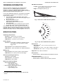
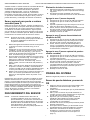
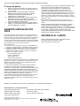
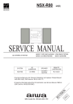
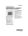
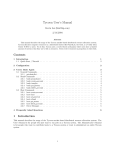
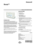
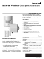
WSK-24 Wireless Occupancy Solution
INSTALLATION INSTRUCTIONS
that the room is unoccupied it closes a dry contact
switch. After the thermostat or controller recognizes the
contact closure, it places the thermostat in economy
setback mode, which provides energy savings for when
the room is unoccupied.
FEATURES
• Wireless system provides quick and easy
installation
• Pre-configured door sensor and occupancy
sensor
• Guest comfort is maintained by never turning off
HVAC equipment when someone is in the room –
even if they are sleeping
• Fuse protection
• Long battery life
• Low battery indication
• Receiver memory retained after power loss
• Optional sliding door/window sensor can be
easily added
Contents
PRODUCT DESCRIPTION
The WSK-24 Wireless Occupancy Solution automatically
controls HVAC equipment by determining when a room is
occupied. The WSK-24 uses the combination of an
occupancy sensor and a door switch to provide optimal
control. The WSK-24 is packaged in a kit that includes
the following components:
• One 24V dry contact receiver
• One wireless PIR (passive infrared receiver)
occupancy sensor with mounting kit
• One wireless door sensor with mounting kit
• One wiring harness.
The receiver can be wired into any thermostat or
controller that supports the connection of a remote
setback device. The receiver communicates wirelessly to
a PIR occupancy sensor, a door sensor, and an optional
2nd door/window sensor. After the receiver determines
Product Description .................................................... 1
Features ..................................................................... 1
Ordering Information .................................................. 2
Specifications ............................................................. 2
Installation .................................................................. 3
Thermostat Configuration ................................. 3
Wiring ................................................................ 3
Setting the Delay on the Receiver .................... 4
Mounting ........................................................... 4
Battery Replacement ........................................ 6
Operation ................................................................... 6
Door (Zone 1) and PIR Occupancy Motion Sensor
(Zone 2) ............................................................ 6
Optional Sliding Door/Window Sensor (Zone 3) 6
Sensor Discovery ....................................................... 7
System Testing ........................................................... 7
Front Door Sensor & PIR Sensor ..................... 7
2nd Door Sensor ............................................... 7
Limited Two-Year Warranty ........................................ 8
Customer Assistance ................................................. 8
62-0300ES-01
WSK-24 WIRELESS OCCUPANCY SOLUTION
ORDERING INFORMATION
ORDERING INFORMATION
PIR Detection Pattern:
Length: 3 to 8 meters when mounted 2 meters
above the floor (see Fig. 1)
When purchasing replacement and modernization
products from your TRADELINE® wholesaler or
distributor, refer to the TRADELINE® catalog or price
sheets for complete ordering number. Orders can also be
placed at http://customer.honeywell. com.
Angle: 140 degrees (see Fig. 2)
M
2
If you have additional questions, need further information,
or would like to comment on our products or services,
please write or phone:
1. Your local Honeywell Automation and Control
Products sales office (check the white pages of your
phone directory).
2. Honeywell Customer Care
1885 Douglas Drive North
Minneapolis, Minnesota 55422-4386
(763) 954-5720
3. In Canada–Honeywell Limited/Honeywell Limitée,
35 Dynamic Drive, Toronto, Ontario M1V 4Z9.
International sales and service offices are located in all
principal cities of the world. Manufacturing is in Australia,
Canada, Finland, France, Germany, Japan, Mexico, the
Netherlands, Spain, Taiwan, United Kingdom, and U.S.A.
1
1
2
C3
4 B 5
6
LENGTH 3 ~ 8 M
7
M29142
Fig. 1. Side view of PIR detection pattern.
70°
60°
50°
40°
30°
20°
10°
0°
SPECIFICATIONS
10°
20°
Operating Temperature:
30°
Receiver: -21 to 60°C (-5 to 140°F)
Door
Sensora:
40°
-20 to 60°C (-4 to 140°F)
50°
PIR Sensor: -20 to 40°C (-4 to 104°F)
70°
Power Supply:
Receiver: 24 Vac/Vdc at 50/60 Hz; Standby power
consumption 15 mA; Channel 1 relay
output, N.O.
M
A 8
60°
M29143
Fig. 2. Top view of PIR detection pattern.
Dimensions:
Door Sensora: Two CR2032 lithium batteries
Door Sensora: 1.4 x 2.3 x 0.6 in (35.8 x 57.6 x
15.2 mm)
PIR Sensor: Three AAA E92 1.5V alkaline batteries
Receiver: 3.6 x 3.4 x 1.2 in (91.4 x 86.4 x 30.5 mm)
PIR Sensor: 2.8 x 3.9 x 1.1 in (71 x 100 x 28 mm)
Battery Life:
Door Sensora: Two years (under normal usage)
Approvals: FCC Part 15 Class B
PIR Sensor: One year (under normal usage)
Accessories:
• 50037735-001: Optional Sliding Door/Window Sensor
Receiver Operating Frequency:
Receiver: 433.92 MHz
Door Sensora: 433.92 MHz
Replacement Parts:
• 50037737-001: Wireless Receiver
• 50037736-001: Wireless PIR Occupancy Sensor
PIR Sensor: 433.92 MHz
Receiver Frequency Range:
• With antenna exposed:
• Open Range: 200 ft.
• Typical Range: 100 ft.
• With antenna coiled inside receiver:
• Open Range: 50 ft.
• Typical Range: 40 ft.
a and
50037735-001, the optional sliding door/window
sensor
62-0300ES—01
2
INSTALLATION
WSK-24 WIRELESS OCCUPANCY SOLUTION
INSTALLATION
Table 2. SuitePRO™ Installer Setup (IS) Codes.
IS
Code
When Installing this Product…
1.
2.
3.
Read these instructions carefully. Failure to follow
them could damage the product or cause a
hazardous condition.
Check the ratings given in the instructions and on
the product to make sure the product is suitable for
your application.
Installer must be a trained and experienced service
technician.
Code
Option
Description Value
WARNING
Risk of electrical shock.
Can cause severe injury, property damage or
death.
Disconnect power supply before installation and
before servicing.
IMPORTANT
The thermostat may be a line voltage powered
device. All wiring must comply with national and
local electrical codes, ordinances and
regulations.
The WSK-24 must be powered by an Approved
24 Vac, Class 2, NEMA rated transformer.
Thermostat Configuration
Remote
50-70 Range is 50 to 70°F
Setback for
(10 to 21°C)
Heating
21
Remote
72-90 Range is 72 to 90°F
Setback for
(22 to 32°C)
Cooling
Wiring
Prepare Thermostat for Receiver Wiring
Turn off the thermostat and remove the power source
from the thermostat.
WARNING
Risk of electrical shock.
Can cause severe injury, property damage or
death.
Disconnect power supply before servicing.
The receiver has a normally open dry contact relay.
Therefore, the thermostat should be set so that the relay
on the thermostat is normally closed.
Use Table 2 or Table 1 to determine the desired Installer
Codes for the thermostat being used with the WSK-24.
CAUTION
Equipment Damage Hazard.
Improper removal can damage the thermostat.
Carefully follow the thermostat removal directions.
Table 1. MultiPRO™ Installer Setup Codes.
Code
Description
Option
Value
Option Description
0160
Schedule Options 0
Non-Programmable
0340
(Nonprogram
mable)
Remote Temp
Sensor/Remote
Setback/
Changeover
Input
Remote Setback
0341
Delay for Remote 0
Setback
2
No Delay
0342
Override Option
0
No Override during
unoccupied
1
Override during
unoccupied
5
Receiver and Thermostat Terminal Wiring
Table 3. Wiring Designations
Receiver
Harness
Wire
Red
Two Minute Delay
0343
Unoccupied
50-65 Range is 50 to 65°F
Heating Setpoint
(10 to 18°C)
0346
Unoccupied
75-90 Range is 75 to 90°F
Cooling Setpoint
(24 to 30°C)
4
Hotel Card enabled N.C. with
1 second software delay
going from UnOccupied to
Occupied;
30 minute delay going from
Occupied to UnOccupied.
20
Refer to the thermostat’s installation instructions for
programming, mounting, and wiring the thermostat.
IS
Code
2
Remote
Setback
19
Option Description
Hotel Card enabled N.C. with
1 second software delay
going from UnOccupied to
Occupied;
2 minute delay going from
Occupied to UnOccupied.
3
Typical
Thermostat
Terminals
R
Connection
24 Vac Power
White
C
24 Vac Common
White/
Brown
Sc
Dry Contact; Normally
Open
Brown
Sb
Dry Contact; Common
62-0300ES—01
WSK-24 WIRELESS OCCUPANCY SOLUTION
INSTALLATION
TO THERMOSTAT
TOP END VIEW
WIRING
HARNESS
JUMPER
PUSHBUTTON
RECEIVER
1. WIRE RED AND WHITE WIRES TO
24 VAC POWER AND COMMON.
2. WIRE WHITE/BROWN AND
BROWN WIRES TO DRY CONTACT
TERMINALS ON THERMOSTAT.
BOTTOM END VIEW
ANTENNA
M29150
WIRING
HARNESS
CONNECTOR
Fig. 3. Receiver and wiring harness.
Using Table 3 on page 3 and Fig. 3, wire the harness to
the thermostat and connect the harness to the receiver.
1. Wire the red and white power leads on the wiring
harness into the power terminals on the thermostat.
2. Wire the white/brown and brown dry contact leads
on the wiring harness into the remote setback
terminals on the thermostat.
3. Plug the wiring harness into the receiver. The
harness is keyed and fits only one way.
4. Supply power to the thermostat.
5. The LED on the receiver flashes twice to show it
has power.
6. Continue with “Setting the Delay on the Receiver”.
LED
M29151
Fig. 4. Receiver components.
Mounting the Door Sensor
1. Remove battery tab before installation. See Fig. 5.
Setting the Delay on the Receiver
Refer to Fig. 4 and position the jumper to the desired
delay option:
Position the jumper near the pushbutton:
— Front Door - 3 minute delay
— 2nd optional door - 1 minute delay
Position the jumper away from the pushbutton (default
position):
— Front Door - 15 second delay
— 2nd optional door - 1 minute delay
PULL OUT
BEFORE USE
M29152
Fig. 5. Battery tab removal.
2. Remove the plastic mounting bracket from the door
sensor housing.
3. Place the mounting bracket for the door sensor high
on the frame of the front door. Secure the bracket to
the door frame by using the two screws or adhesive
tape provided. See Fig. 6 on page 5.
The receiver delay and the delay that is programmed in
the thermostat will be combined to provide an overall
delay.
Mounting
Mounting the Receiver
The receiver can be mounted behind the thermostat in the
wall, inside the fan coil unit, or mounted on the wall.
Mounting screws or double-sided adhesive tape can be
used to mount the receiver.
62-0300ES—01
4
INSTALLATION
WSK-24 WIRELESS OCCUPANCY SOLUTION
8. Secure the magnet to the door by using the two
screws or adhesive tape provided. An optional
spacer is provided, as well. See Fig. 9.
SCREWS TO
HOLD BRACKET
MOUNTING
BRACKET
TAB TO RELEASE
DOOR SENSOR
SCREWS TO
MAGNET OR
SPACER
ADHESIVE
TAPE
OPTIONAL
SPACER
M29153
Fig. 6. Door sensor bracket mounting.
4.
ADHESIVE
TAPE
Make sure the notched side of the door sensor is
pointing in the direction that you will mount the
magnet. See Fig. 7 and Fig. 8.
M29156
Fig. 9. Door magnet mounting options.
9. Open and close the door to ensure that there is no
interference.
CHECK THE DOOR SENSOR FUNCTION
1. Open the door and verify that the LED on the door
sensor flashes three times when the contact is
opened.
2. Close the door and verify that the LED on the door
sensor flashes another three times.
TAB
NOTCHES
Mounting the PIR Occupancy Motion Sensor
TAB
NOTCHES
M29154
PLASTIC
CONICAL
ANCHORS
Fig. 7. Door sensor tab notches.
5.
6.
7.
Snap the sensor in place.
Align one end of the magnet with the notched side
of the door sensor housing.
Mount the magnet a maximum of 3/4 in. (19 mm)
from the door sensor, as illustrated in Fig. 8.
PIR BACK
PLATE
ADHESIVE
TAPE
MOUNTING
SCREWS
TO FIX THE BRACKET
BRACKET
TAB
NOTCHES
MUST FACE
THE MAGNET
SCREW TO
RELEASE
COVER
M29157
Fig. 10. PIR occupancy motion sensor mounting
options.
1
1
COVER
SCREWS
TO HOLD
SENSOR
1. Take off the cover by removing the cover release
screw on the bottom of the PIR back plate.
2. Power the PIR sensor by inserting the three AAA
batteries provided. See Fig. 12 for proper battery
orientation.
3. Secure the PIR sensor to the wall using one of the
following three options
MAXIMUM DISTANCE BETWEEN SENSOR AND
MAGNET 3/4 (19).
M29155
Fig. 8. Maximum distance between door sensor and
magnet.
5
62-0300ES—01
WSK-24 WIRELESS OCCUPANCY SOLUTION
4.
a. Wall Mount option 1: Use the adhesive tape to
secure the PIR back plate to the wall.
b. Wall mount option 2: Using either the top or
bottom two holes of the PIR back plate, insert
the two long screws to secure the PIR back
plate to the wall.
c. Ceiling mount option: Align the mounting
bracket and PIR back plate as shown in Fig. 10.
Insert the two small screws into the top holes of
the back plate and secure it to the bracket. Use
the two long screws (and, if necessary, the
optional plastic anchors) and mount the bracket
and PIR back plate to the ceiling.
Replace the PIR sensor cover and replace the
cover release screw on the bottom of the sensor.
CHECK THE PIR OCCUPANCY MOTION SENSOR FUNCTION
1. Create motion in front of the PIR sensor and verify
that its LED flashes three times when motion is
detected.
• The PIR sensor continues to flash while motion
is detected.
2. Cover the PIR sensor and verify that its LED stops
flashing.
3. Uncover the PIR sensor.
Battery Replacement
For correct battery replacement, note the battery polarity
orientations in Fig. 11 and Fig. 12.
LED STATUS
INDICATOR
TAB TO
RELEASE
THE COVER
SCREW TO
HOLD PCB
PCB
BATTERY
BACK
SCREW TO
HOLD PCB
M29158
Fig. 11. Door sensor battery replacement.
OPERATION
Low-Battery Indication
When a low battery condition is detected in the door
sensor or the PIR occupancy sensor, the LED status
indicator on the device flashes for four (4) seconds.
OPERATION
Door (Zone 1) and PIR Occupancy Motion
Sensor (Zone 2)
The door sensor and PIR occupancy motion sensor are
packaged factory-configured to the receiver. There is no
need for the receiver to discover these sensors. The door
and PIR sensors wirelessly connect to the receiver right
out of the box. Simply wire and mount the receiver and
sensors and the system will work properly.
When the door is opened and then closed, a signal is sent
to the PIR sensor to begin looking for motion. As soon as
the PIR senses someone is in the room, the receiver
clicks the relay to turn the thermostat back into the
occupied setpoints. If the person does not leave the room,
the thermostat will always stay in the occupied mode,
regardless if the PIR sensor stops sensing motion. This
provides a comfortable environment for guests and
ensures that the HVAC equipment does not turn off while
guests are sleeping.
When a guest opens and closes the door and leaves the
room, the PIR sensor starts looking for motion again. If
the PIR sensor does not sense motion, the receiver
closes the relay after 15 seconds or 3 minutes (depending
on how the jumper is positioned) and the thermostat goes
into the unoccupied economy mode. The overall delay
depends on the delay that is programmed in the
thermostat.
The PIR sensor always overrides the unoccupied
economy mode, as soon as it senses motion. For
example, if there are two guests in the room and guest A
is in the bathroom while guest B leaves the room, the
thermostat goes into economy setback mode if no motion
is detected. As soon as guest A leaves the bathroom and
enters the main room, the PIR senses motion and returns
the thermostat to normal operation. The thermostat
continues in normal operation until someone opens and
closes the front door and the PIR stops sensing motion.
COVER
Optional Sliding Door/Window Sensor
(Zone 3)
PCB
Because the sliding door/window sensor is an optional
accessory, the receiver needs to discover this new zone.
After the sliding door/window sensor is powered, follow
these steps to add the optional sliding door/window
sensor. It is easiest to do this before the sensor is
mounted.
LED STATUS
INDICATOR
SCREW TO
HOLD PCB
BATTERY
NOTE: The sliding door/window sensor is identical to
the door sensor supplied with the WSK-24
Wireless Occupancy Solution.
1. Remove the battery tab from the sliding door/
window sensor. See Fig. 5 on page 4.
2. Make sure the sliding door/window sensor and
magnet are close to each other, within 3/4 in. (19
mm), and that the tab notches on the sensor face
the magnet. See Fig. 8 on page 5.
BACK
SCREW TO
HOLD COVER
M29159
Fig. 12. PIR occupancy sensor battery replacement.
62-0300ES—01
6
SENSOR DISCOVERY
3.
4.
5.
At the receiver and press the black pushbutton
three times for Zone 3 (see Fig. 4 on page 4). The
red LED on the opposite side of the receiver will
flash three times. See Fig. 4 on page 4 for location
of the pushbutton and LED.
Open and close Zone 3 by moving the magnet
away from the sliding door/window sensor and
bringing it back to contact. The red LED on the
receiver will flash another 3 times to indicate that
Zone 3 is discovered.
Mount the sliding door/window sensor and magnet
using the same mounting procedure as described in
“Mounting the Door Sensor” on page 4.
After the sliding door or window is opened and left open
for longer than 1 minute, the receiver closes the relay and
the thermostat goes into the unoccupied economy mode.
The overall delay depends on the delay that is
programmed in the thermostat. The occupant cannot
change the thermostat settings while the sliding door or
window is open. As soon as the sliding door or window is
closed, the thermostat returns to normal operation.
WSK-24 WIRELESS OCCUPANCY SOLUTION
Adding Zone 3 (Optional Sliding Door/Window
Sensor)
1. Make sure the PIR sensor is covered.
2. Make sure the sliding door/window contact is
closed.
3. Press the black pushbutton on the receiver three
times. The red LED on the receiver flashes three
times.
4. Now activate the sliding door/window sensor by
removing the magnet. The red LED on the receiver
flashes three times to confirm the device has been
discovered.
5. Uncover the PIR sensor.
SYSTEM TESTING
Perform the following to test the sensors.
Front Door Sensor & PIR Sensor
1. Position the jumper away from the pushbutton to
set the minimal time delay (15 seconds).
2. Cover the PIR sensor so it cannot sense motion.
3. Open and close the front door sensor. The receiver
closes its relay after 15 seconds, and you will hear
the relay click on the receiver.
4. Wait for the thermostat to go into unoccupied mode.
The overall delay will depend on the additional time
delay that is configured in the thermostat.
5. Uncover the PIR sensor so that it can now sense
motion.
6. The receiver opens the relay and the thermostat
returns to occupied mode immediately.
7. Position the jumper back to the desired time delay.
(See “Setting the Delay on the Receiver” on
page 4.)
SENSOR DISCOVERY
NOTE: The WSK-24 Wireless Occupancy Solution
comes with the front door sensor and the PIR
occupancy motion sensor already discovered by
the receiver. There should be no need to
rediscover these devices. However, this
information is provided for troubleshooting
purposes.
Deleting all Sensors
1.
2.
Press and hold the black pushbutton (see Fig. 4 on
page 4) on the receiver for six (6) seconds.
The red LED on the receiver flashes once to
confirm that all sensors have been deleted.
Adding Zone 1 (Door Sensor)
1.
2.
3.
4.
5.
2nd Door Sensor
1. Open the 2nd door sensor. The receiver closes its
relay after 1 minute, and you will hear the relay click
on the receiver.
2. Wait for the thermostat to go into unoccupied mode.
The overall delay depends on the additional time
delay that is configured in the thermostat.
3. Keep the door open and move in front of the PIR
sensor so that it can sense motion. The thermostat
should remain in the unoccupied mode.
4. Close the 2nd door sensor. The receiver opens its
relay and the thermostat returns to occupied mode
immediately.
Make sure the PIR sensor is covered.
Make sure the door contact is closed.
Press the black pushbutton on the receiver one
time. The red LED on the receiver flashes once.
Now activate the door sensor by removing the
magnet. The red LED on the receiver flashes once
to confirm the device has been discovered.
Uncover the PIR sensor.
Adding Zone 2 (PIR Occupancy Motion Sensor)
1.
2.
3.
Make sure the PIR sensor is covered.
Press the black pushbutton on the receiver two
times. The red LED on the receiver flashes twice.
Now activate the PIR sensor by uncovering the
sensor and moving in front of it. The red LED on the
receiver flashes twice to confirm the device has
been discovered.
7
62-0300ES—01
LIMITED TWO-YEAR WARRANTYWSK-24 WIRELESS OCCUPANCY SOLUTION
LIMITED TWO-YEAR WARRANTY
Honeywell warrants this product, excluding battery, to be free
from defects in the workmanship or materials, under normal use
and service, for a period of two (2) years from the date of
purchase by the consumer. If, at any time during the warranty
period, the product is defective or malfunctions, Honeywell shall
repair or replace it (at Honeywell’s option) within a reasonable
period of time.
If the product is defective,
(i) return it, with a bill of sale or other dated proof of purchase,
to the retailer from which you purchased it, or
(ii) package it carefully, along with proof of purchase (including
date of purchase) and a short description of the malfunction,
and mail it, postage prepaid, to the following address:
Honeywell Return Goods
Dock 4 - MN10-3860
1885 Douglas Dr. N
Golden Valley, MN 55422
This warranty does not cover removal or reinstallation costs.
This warranty shall not apply if it is shown by Honeywell that the
defect or malfunction was caused by damage which occurred
while the product was in the possession of a consumer.
Honeywell’s sole responsibility shall be to repair or replace the
product within the terms stated above. HONEYWELL SHALL
NOT BE LIABLE FOR ANY LOSS OR DAMAGE OF ANY KIND,
INCLUDING ANY INCIDENTAL OR CONSEQUENTIAL
DAMAGES RESULTING, DIRECTLY OR INDIRECTLY, FROM
ANY BREACH OF ANY WARRANTY, EXPRESS OR IMPLIED,
OR ANY OTHER FAILURE OF THIS PRODUCT. Some states
do not allow the exclusion or limitation of incidental or
consequential damages, so this limitation may not apply to you.
THIS WARRANTY IS THE ONLY EXPRESS WARRANTY
HONEYWELL MAKES ON THIS PRODUCT. THE DURATION
OF ANY IMPLIED WARRANTIES, INCLUDING THE
WARRANTIES OF MERCHANTABILITY AND FITNESS FOR A
PARTICULAR PURPOSE, IS HEREBY LIMITED TO THE TWO
YEAR DURATION OF THIS WARRANTY. Some states do not
allow limitations on how long an implied warranty lasts, so the
above limitation may not apply to you.
This warranty gives you specific legal rights, and you may have
other rights which vary from state to state.
If you have any questions concerning this warranty,
please write Honeywell Customer Relations, 1985
Douglas Dr., Golden Valley, MN 55422 or call 1-800-4681502, Monday-Friday, 7:00 a.m. to 5:30 p.m., Central
time. In Canada, write Retail Products ON15-02H,
Honeywell Limited/Honeywell Limitée, 35 Dynamic Drive,
Scarborough, Ontario M1V4Z9.
CUSTOMER ASSISTANCE
If you have any questions about the operation of your
thermostat or this system, please go to
http://customer.honeywell. com
MultiPro™ and SuitePro™ are trademarks of Honeywell International Inc..
Automation and Control Solutions
Honeywell International Inc.
Honeywell Limited-Honeywell Limitée
1985 Douglas Drive North
35 Dynamic Drive
Golden Valley, MN 55422
Toronto, Ontario M1V 4Z9
customer.honeywell.com
® U.S. Registered Trademark
© 2009 Honeywell International Inc.
62-0300ES—01 M.S. 03-09
Solución inalámbrica de detección de
ocupación WSK-24
INSTRUCCIONES DE INSTALACIÓN
con un sensor de puerta y con un 2do sensor de puerta o
ventana opcional. Después de que el receptor determina
que la habitación no está ocupada, cierra un interruptor
de contacto seco. Después de que el termostato o
controlador reconoce el cierre del contacto, ponen el
termostato en modo inicial de economía, que permite
ahorrar energía cuando la habitación no está ocupada.
CARACTERÍSTICAS
• Sistema inalámbrico de rápida y fácil instalación
• Sensor de puerta y sensor de ocupación
preconfigurado
• Invitados más cómodos debido a que el equipo de
climatización nunca se apaga si hay alguien en la
habitación, aunque esté durmiendo
• Protección por fusibles
• Larga duración de la batería
• Indicación de batería baja
• Retención de la memoria del receptor después de
una pérdida de potencia
• Fácil adición de sensor opcional para puerta o
ventana corrediza
Contenido
DESCRIPCIÓN DEL PRODUCTO
La solución inalámbrica de detección de ocupación
WSK-24 controla automáticamente el equipo de
climatización, determinando cuándo está ocupada una
habitación. La WSK-24 usa la combinación de un sensor
de ocupación y un interruptor de puerta para ofrecer el
mejor control. La WSK-24 viene en un kit que incluye los
siguientes componentes:
• Un receptor de contacto seco de 24 V
• Un sensor de ocupación de receptor pasivo infrarrojo
(PIR) inalámbrico con kit de montaje
• Un sensor de puerta inalámbrico con kit de montaje
• Un mazo de cables
El receptor se puede cablear a cualquier termostato o
controlador que admita la conexión de un dispositivo
remoto de puesta a cero. El receptor se comunica de
manera inalámbrica con el sensor de ocupación de PIR,
Descripción del producto ............................................ 1
Características ........................................................... 1
Información sobre pedidos ......................................... 2
Especificaciones ........................................................ 2
Instalación .................................................................. 3
Configuración del termostato ............................ 3
Cableado .......................................................... 3
Configuración del retraso en el receptor ........... 4
Montaje ............................................................. 4
Reemplazo de la batería ................................... 6
Operación ................................................................... 6
Sensor de puerta (zona 1) y sensor de movimiento
de ocupación de PIR (zona 2) .......................... 6
Sensor opcional para puerta o ventana corrediza
(zona 3) ............................................................. 7
Descubrimiento del sensor ......................................... 7
Prueba del sistema .................................................... 7
Sensor de puerta delantera y sensor de PIR .... 7
2º sensor de puerta .......................................... 8
Garantía limitada de dos años ................................... 8
Asistencia al cliente .................................................... 8
62-0300ES-01
SOLUCIÓN INALÁMBRICA DE DETECCIÓN DE OCUPACIÓN WSK-24
INFORMACIÓN SOBRE PEDIDOS
INFORMACIÓN SOBRE PEDIDOS
Patrón de detección de PIR:
Longitud: 3 a 8 metros, si se monta a 2 metros por
sobre el suelo (consulte la Fig. 1)
Al comprar productos de reemplazo y modernización del
mayorista o distribuidor TRADELINE®, consulte en el
catálogo u hoja de precios de TRADELINE® los números
de solicitud completos. También puede solicitar pedidos
en http://customer.honeywell. com.
Ángulo: 140 grados (consulte la Fig. 2)
M
2
Si tiene más preguntas, necesita más información o
desea hacer comentarios acerca de nuestros productos o
servicios, escriba o llame a:
1. La oficina de ventas local de productos de
automatización y control Honeywell (consulte las
páginas blancas de su directorio telefónico).
2. Honeywell Customer Care
1885 Douglas Drive North
Minneapolis, Minnesota 55422-4386
(763) 954-5720
3. En Canadá: Honeywell Limited/Honeywell Limitée,
35 Dynamic Drive, Toronto, Ontario M1V 4Z9.
Contamos con oficinas internacionales de ventas y
servicio en todas las principales ciudades de mundo.
Fabricamos en Australia, Canadá, Finlandia, Francia,
Alemania, Japón, México, los Países Bajos, España,
Taiwán, Reino Unido y EE. UU.
1
1
2
C3
4 B 5
6
LONGITUD 3 ~ 8 M
7
A 8
M
MS29142
Fig. 1. Vista lateral del patrón de detección de PIR.
70°
60°
50°
40°
30°
20°
10°
0°
ESPECIFICACIONES
10°
20°
Temperatura de funcionamiento:
30°
Receptor: -21 a 60 °C (-5 a 140 °F)
40°
Sensor de puertaa: -20 a 60 °C (-4 a 140 °F)
50°
Sensor de PIR: -20 a 40 °C (-4 a 104 °F)
70°
Dimensiones:
Sensor de puertaa: 35,8 x 57,6 x 15,2 mm (1,4 x 2,3 x
0,6 pulg.)
Sensor de puertaa : Dos baterías de litio CR2032
Receptor: 91,4 x 86,4 x 30,5 mm (3,6 x 3,4 x 1,2 pulg.)
Sensor de PIR: Tres baterías alcalinas AAA E92 1,5 V
Sensor de PIR: 71 x 100 x 28 mm (2,8 x 3,9 x 1,1
pulg.)
Duración de la batería:
Sensor de puertaa: Dos años (en uso normal)
M29143
Fig. 2. Vista superior del patrón de detección de PIR.
Suministro de energía:
Receptor: 24 V CA/V CC a 50/60 Hz; consumo de
energía de reserva: 15 mA; salida del relé
del canal 1: normalmente abierto
60°
Autorizaciones: FCC parte 15, clase B
Sensor de PIR: Un año (en uso normal)
Frecuencia de utilización del receptor:
Receptor: 433,92 MHz
Sensor de puertaa: 433,92 MHz
Sensor de PIR: 433,92 MHz
Banda de frecuencias del receptor:
• Con la antena expuesta:
• Banda abierta: 60,9 m (200 pies)
• Banda típica: 30,4 m (100 pies)
• Con la antena enrollada dentro del receptor:
• Banda abierta: 15,2 m (50 pies)
• Banda típica: 12,1 m (40 pies)
Accesorios:
• 50037735-001: Sensor opcional para puerta o ventana
corrediza
Repuestos:
• 50037737-001: Receptor inalámbrico
• 50037736-001: Sensor de ocupación de PIR
inalámbrico
ay
50037735-001, el sensor opcional para puerta o ventana corrediza
62-0300ES—01
2
INSTALACIÓN
SOLUCIÓN INALÁMBRICA DE DETECCIÓN DE OCUPACIÓN WSK-24
INSTALACIÓN
Tabla 2. Códigos de configuración de instalador (IS)
de SuitePRO™.
Al instalar este producto…
1.
2.
3.
IS
Descripción Opción
Código del código Valor
Lea cuidadosamente estas instrucciones. No
seguirlas puede dañar el producto u ocasionar una
condición peligrosa.
Consulte los regímenes indicados en las
instrucciones y en el producto para asegurarse de
que éste sea adecuado para su aplicación.
El instalador debe ser un técnico de servicio
capacitado y con experiencia.
WARNING
Riesgo de descarga eléctrica.
Puede provocar graves lesiones, daño a la
propiedad o la muerte.
Desconecte el suministro de energía antes de
instalar el aparato y de realizarle mantenimiento.
IMPORTANTE
El termostato puede ser un dispositivo
alimentado por tensión de línea. Todo el
cableado debe cumplir con los códigos,
ordenanzas y reglamentos eléctricos nacionales
y locales.
Consulte las instrucciones de instalación del termostato
para programarlo, montarlo y cablearlo.
Puesta a cero 50-70
remota del
calentamiento
Rango de 50 a 70 °F
(10 a 21 °C)
21
Puesta a cero 72-90
remota del
enfriamiento
Rango de 72 a 90 °F
(22 a 32 °C)
Cableado
Prepare el termostato para recibir cableado
Apague el termostato y retírele la fuente de alimentación.
El receptor tiene un relé de contacto seco normalmente
abierto. Por lo tanto, el termostato se debe programar de
forma tal que el relé del termostato esté normalmente
cerrado.
WARNING
Riesgo de descarga eléctrica.
Puede provocar graves lesiones, daño a la
propiedad o la muerte.
Desconecte el suministro de energía antes de
mantenimiento servicio al aparato.
Use la Table 1 o la Table 2 para determinar los códigos de
instalador deseados para el termostato que use con la
WSK-24.
Tabla 1. Códigos de configuración de instalador de
MultiPRO™.
IS
Código
Código
Descripción
Opción
Valor
CAUTION
Descripción de la
opción
0160
Opciones de programa 0
No programable
0340
(No
program
-able)
Sensor de temperatura 5
remota/Puesta a cero
remota/Entrada de
cambio
Puesta a cero remota
0341
Retraso de puesta a
cero remota
0
Sin retraso
2
Retraso de dos minutos
0342
Opción de anulación
0
Sin anulación mientras
está desocupada
1
Anulación mientras está
desocupada
4
N.C. activado con tarjeta del hotel
con • Retraso de software de 1
segundo al ir de UnOccupied
(habitación desocupada) a
Occupied (habitación ocupada)
• Retraso de software de 30
minutos al ir de Occupied a
UnOccupied
20
La WSK-24 debe recibir alimentación de un
transformador aprobado de 24 V CA, clase 2
con clasificación NEMA.
Configuración del termostato
2
Puesta a cero
remota
19
Descripción de la opción
N.C. activado con tarjeta del hotel
con • Retraso de software de 1
segundo al ir de UnOccupied
(habitación desocupada) a
Occupied (habitación ocupada)
• Retraso de software de 2
minutos al ir de Occupied a
UnOccupied
Peligro de daño al equipo.
El retiro inadecuado puede provocar daño en
el termostato.
Siga cuidadosamente las instrucciones de retiro
del termostato.
Cableado de terminales del receptor y del
termostato
Tabla 3. Designaciones del cableado
Cable
Terminales
del mazo
típicos
del
del
receptor ermostato
0343
Punto de ajuste de
50-65
calentamiento de
habitación desocupada
Rango de 50 a 65 °F
(10 a 18 °C)
Rojo
0346
Punto de ajuste de
75-90
enfriamiento de
habitación desocupada
Rango de 75 a 90 °F
(24 a 30 °C)
3
Conexión
R
Alimentación de 24 V CA
Blanco
C
24 V CA común
Blanco/café
Sc
Contacto seco; normalmente
abierto
Café
Sb
Contacto seco; común
62-0300ES—01
SOLUCIÓN INALÁMBRICA DE DETECCIÓN DE OCUPACIÓN WSK-24
INSTALACIÓN
Se puede usar tornillos de montaje o cinta adhesiva de
doble faz para montar el receptor.
AL TERMOSTATO
VISTA DE EXTREMO SUPERIOR
MAZO DE CABLES
PUENTE
CONECTOR
RECEPTOR
PULSADOR
1. TIENDA LOS CABLES ROJO Y
BLANCO A LAS TERMINALES DE
ALIMENTACIÓN DE 24 V CA Y
COMÚN.
2. TIENDA LOS CABLES BLANCO/
CAFÉ Y CAFÉ A LAS TERMINALES
DE CONTACTO SECO EN EL
TERMOSTATO.
ANTENA
VISTA DE EXTREMO INFERIOR
MS29150
Fig. 3. Receptor y mazo de cables.
Según la Tabla 3 en la página 3 y la Fig. 3, cablee el
mazo al termostato y conecte el mazo al receptor.
1. Cablee los conductores de alimentación rojo y
blanco del mazo de cables a las terminales de
potencia del termostato.
2. Cablee los conductores blancos/cafés de contactos
secos del mazo de cables a las terminales del
dispositivo remoto de puesta a cero del termostato.
3. Enchufe el mazo de cables en el receptor. El mazo
es enchavetado y encaja en una sola posición.
4. Conecte el termostato a la alimentación.
5. El LED del receptor parpadea dos veces para
indicar que tiene energía.
6. Continúe con “Configuración del retraso en el
receptor”.
CONECTOR
DEL MAZO
DE CABLES
LED
MS29151
Fig. 4. Componentes del receptor.
Montaje del sensor de puerta
1. Retire la lengüeta de la batería antes de comenzar
la instalación. Consulte la Fig. 5.
Configuración del retraso en el receptor
Consulte la Fig. 4 y seleccione la opción de retraso
deseada para el puente conector:
Ubique el puente conector cerca del pulsador:
— Puerta delantera: retraso de 3 minutos
— 2ª puerta opcional: retraso de 1 minuto
Ubique el puente conector lejos del pulsador (ubicación
predeterminada):
— Puerta delantera: retraso de 15 segundos
— 2ª puerta opcional: retraso de 1 minuto
RETIRE ANTES
DE USAR
MS29152
Fig. 5. Retiro de la lengüeta de la batería.
El retraso del receptor y el retraso programado en el
termostato se combinarán en un retraso promedio.
2. Retire el soporte de montaje plástico del
alojamiento del sensor de puerta.
3. Coloque el soporte de montaje del sensor de puerta
alto en el marco de la puerta delantera. Fije el
soporte en el marco de la puerta con los dos
tornillos o la cinta adhesiva proporcionada.
Consulte la Fig. 6 en la página 5.
Montaje
Montaje del receptor
El receptor se puede montar detrás del termostato dentro
de la pared, dentro del ventiloconvector o en la superficie
de la pared.
62-0300ES—01
4
INSTALACIÓN
SOLUCIÓN INALÁMBRICA DE DETECCIÓN DE OCUPACIÓN WSK-24
8. Fije el imán a la puerta con los dos tornillos o la
cinta adhesiva proporcionada. También se
proporciona un distanciador opcional. Consulte la
Fig. 9.
TORNILLOS PARA
SOSTENER EL
SOPORTE
SOPORTE DE
MONTAJE
LENGÜETA PARA
LIBERAR EL SENSOR
DE PUERTA
TORNILLOS
PARA EL IMÁN O
EL DISTANCIADOR
CINTA
ADHESIVA
MS29153
DISTANCIADOR
OPCIONAL
Fig. 6. Montaje del soporte del sensor de puerta.
4.
CINTA
ADHESIVA
Asegúrese de que el lado con muescas del sensor
de puerta apunte a la dirección en la que montará el
imán. Consulte la Fig. 7 y Fig. 8.
MS29156
Fig. 9. Opciones de montaje del imán de puerta.
9. Abra y cierre la puerta para asegurarse de que no
haya interferencia.
COMPRUEBE EL FUNCIONAMIENTO DEL SENSOR DE PUERTA
1. Abra la puerta y verifique que el LED del sensor de
puerta parpadee tres veces si el contacto está
abierto.
2. Cierre la puerta y verifique que el LED del sensor
de puerta parpadee otras tres veces.
MUESCAS DE
LENGÜETAS
Montaje del sensor de movimiento de ocupación
de PIR
MUESCAS DE
LENGÜETAS
MS29154
CUBIERTA
Fig. 7. Muescas de lengüetas del sensor de puerta.
5.
6.
7.
ANCLAJES
DE PLÁSTICO
CÓNICOS
Inserte el sensor en su posición.
Alinee un extremo del imán con el lado con
muescas del alojamiento del sensor de puerta.
Monte el imán a un máximo de 19 mm (3/4 pulg.)
del sensor de puerta, como se ilustra en la Fig. 8.
TORNILLOS PARA
SOSTENER EL
SENSOR
PLACA
POSTERIOR
DEL PIR
LAS MUESCAS DE
LENGÜETAS DEBEN
ESTAR DE CARA AL IMÁN
CINTA
ADHESIVA
SOPORTE DE
TORNILLOS
MONTAJE
PARA FIJAR
EL SOPORTE
1
TORNILLO DE
LIBERACIÓN DE
LA CUBIERTA
MS29157
Fig. 10. Opciones de montaje del sensor de
movimiento de ocupación de PIR.
1
1. Retire la cubierta sacando el tornillo de liberación
de la cubierta en la parte inferior de la placa
posterior del PIR.
2. Inserte las tres baterías AAA proporcionadas para
encender el sensor de PIR. Consulte la Fig. 12 para
conocer la orientación correcta de la batería.
3. Fije el sensor de PIR a la pared mediante una de
las siguientes tres opciones
DISTANCIA MÁXIMA ENTRE EL SENSOR Y EL IMÁN DE
19 MM (3/4 PULG.)
MS29155
Fig. 8. Distancia máxima entre el sensor de puerta y el
imán.
5
62-0300ES—01
SOLUCIÓN INALÁMBRICA DE DETECCIÓN DE OCUPACIÓN WSK-24
4.
a. Montaje en pared, opción 1: use la cinta adhesiva para fijar la placa posterior del PIR a la
pared.
b. Montaje en pared, opción 2: inserte los dos
tornillos largos en los dos orificios superiores o
inferiores de la placa posterior del PIR para
fijarla a la pared.
c. Opción de montaje en el techo: alinee el
soporte de montaje y la placa posterior del PIR
como se muestra en la Fig. 10. Inserte los dos
tornillos pequeños en los orificios superiores de
la placa posterior y fíjela al soporte. Con los dos
tornillos largos (y, si es necesario, los anclajes
de plástico opcionales) monte el soporte y la
placa posterior del PIR al techo.
Vuelva a colocar la cubierta del sensor del PIR y el
tornillo de liberación de la cubierta en la parte
inferior del sensor.
COMPRUEBE EL FUNCIONAMIENTO DEL SENSOR DE
MOVIMIENTO DE OCUPACIÓN DE PIR
1. Genere movimiento delante del sensor de PIR y
verifique que el LED parpadee tres veces si detecta
movimiento.
• El sensor de PIR continúa parpadeando
mientras no se detecte movimiento.
2. Cubra el sensor de PIR y verifique que el LED deje
de parpadear.
3. Destape el sensor de PIR.
OPERACIÓN
LED INDICADOR
DE ESTADO
CUBIERTA
PCB
BATERÍA
TORNILLO
PARA
SOSTENER
PCB
PARTE
POSTERIOR
TORNILLO
PARA
SOSTENER
LA CUBIERTA
MS29159
Fig. 12. Reemplazo de la batería del sensor de
ocupación de PIR
Indicación de batería baja
Reemplazo de la batería
Cuando se detecta un estado de batería baja del sensor
de puerta o del sensor de ocupación de PIR, el LED
indicador de estado del dispositivo parpadea durante
cuatro (4) segundos.
Para el correcto reemplazo de la batería, observe las
orientaciones de polaridad de la batería en la Fig. 11 y en
la Fig. 12.
OPERACIÓN
Sensor de puerta (zona 1) y sensor de
movimiento de ocupación de PIR (zona 2)
LED INDICADOR
DE ESTADO
LENGÜETA PARA
LIBERAR LA
CUBIERTA
TORNILLO PARA
SOSTENER PCB
PCB
BATERÍA
TORNILLO
PARA SOSTENER
PCB
PARTE
POSTERIOR
MS29158
Fig. 11. Reemplazo de la batería del sensor de puerta
El sensor de puerta y el sensor de movimiento de
ocupación de PIR vienen configurados de fábrica con el
receptor. No es necesario que el receptor descubra estos
sensores. Los sensores de puerta y de PIR se conectan
de manera inalámbrica al receptor apenas se sacan de la
caja. Sólo cablee y monte el receptor y los sensores, y el
sistema funcionará correctamente.
Cuando se abre y luego se cierra la puerta, se envía una
señal al sensor de PIR para que comience a buscar
movimiento. Apenas el PIR detecta la presencia de
alguien en la habitación, el receptor chasquea el relé para
que devuelva al termostato a los puntos de ajuste de
habitación ocupada. Si la persona no sale de la
habitación, el termostato siempre permanecerá en el
modo ocupado, sin importar si el sensor de PIR deja de
detectar movimiento, lo que ofrece un ambiente cómodo
para los visitantes y asegura que el quipo de
climatización no se apague mientras la persona está
durmiendo.
Cuando un visitante abre y cierra la puerta y sale de la
habitación, el sensor de PIR comienza a buscar
movimiento nuevamente. Si el sensor de PIR no detecta
movimiento, el receptor cierra el retraso después de 15
segundos o 3 minutos (dependiendo de la ubicación del
puente conector) y el termostato pasa al modo de
economía de habitación desocupada. El retraso promedio
depende del retraso programado en el termostato.
El sensor de PIR siempre anula el modo de economía de
habitación desocupada apenas detecta movimiento. Por
ejemplo, si hay dos visitantes en la habitación, y el
62-0300ES—01
6
DESCUBRIMIENTO DEL SENSOR
SOLUCIÓN INALÁMBRICA DE DETECCIÓN DE OCUPACIÓN WSK-24
visitante A está en el baño mientras el visitante B sale de
la habitación, el termostato pasa al modo inicial de
economía si no se detecta movimiento. Apenas el
visitante A salga del baño y entre en la habitación
principal, el PIR detecta movimiento y devuelve al
termostato a la operación normal. El termostato continúa
en operación normal hasta que alguien abra y cierre la
puerta delantera y el PIR deje de detectar movimiento.
Eliminación de todos los sensores
1. Mantenga oprimido el pulsador negro (consulte la
Fig. 4 en la página 4) del receptor durante seis (6)
segundos.
2. El LED del receptor parpadea una vez para
confirmar que todos los sensores se han eliminado.
Agregar la zona 1 (sensor de puerta)
1. Asegúrese de que el sensor de PIR esté cubierto.
2. Asegúrese de que el contacto de puerta esté
cerrado.
3. Oprima el pulsador negro del receptor una vez. El
LED rojo del receptor parpadea una vez.
4. Ahora, active el sensor de puerta retirando el imán.
El LED rojo del receptor parpadea una vez para
confirmar que se ha descubierto el dispositivo.
5. Destape el sensor de PIR.
Sensor opcional para puerta o ventana
corrediza (zona 3)
Dado que el sensor de puerta o ventana corrediza es un
accesorio opcional, el receptor debe descubrir esta nueva
zona. Después de que el sensor de puerta o ventana
corrediza se conecta a la alimentación, siga los pasos
que se indican a continuación para agregar el sensor de
puerta o ventana corrediza opcional. Este procedimiento
es más fácil si se realiza antes de montar el sensor.
NOTE: El sensor de puerta o ventana corrediza es
idéntico al sensor de puerta proporcionado con
la solución inalámbrica de detección de
ocupación WSK-24.
1.
2.
3.
4.
5.
Retire la lengüeta de la batería del sensor de puerta
o ventana corrediza. Consulte la Fig. 5 en la
página 4.
Asegúrese de que el sensor de puerta o ventana
corrediza y el imán se encuentren cerca el uno del
otro, dentro de 19 mm (3/4 pulg.), y de que las
muescas de lengüeta del sensor estén de cara al
imán. Consulte la Fig. 8 en la página 5.
En el receptor oprima el pulsador negro tres veces
para la zona 3 (consulte la Fig. 4 en la página 4). El
LED rojo en el lado opuesto del receptor
parpadeará tres veces. Consulte la Fig. 4 en la
página 4 para conocer la ubicación del pulsador y
del LED.
Abra y cierre la zona 3 alejando el imán del sensor
de puerta o ventana corrediza y devolviéndolo al
contacto. El LED rojo del receptor parpadeará otras
3 veces para indicar que se descubrió la zona 3.
Monte el sensor de puerta o ventana corrediza y el
imán con el mismo procedimiento de montaje
descrito en “Montaje del sensor de puerta” en la
página 4.
Después de que la puerta o ventana corrediza se dejan
abiertas durante más de 1 minuto, el receptor cierra el
retraso y el termostato pasa al modo de economía de
habitación desocupada. El retraso promedio depende del
retraso programado en el termostato. El ocupante no
puede cambiar la configuración del termostato mientras la
puerta o ventana corrediza estén abiertas. Apenas se
cierren la puerta o ventana corrediza, el termostato
vuelve a la operación normal.
Agregar la zona 2 (sensor de movimiento de
ocupación de PIR)
1. Asegúrese de que el sensor de PIR esté cubierto.
2. Oprima el pulsador negro del receptor dos veces.
El LED rojo del receptor parpadea dos veces.
3. Ahora, active el sensor de PIR destapando el
sensor y moviéndose frente a él. El LED rojo del
receptor parpadea dos veces para confirmar que se
ha descubierto el dispositivo.
Agregar la zona 3 (sensor opcional de puerta o
ventana corrediza)
1. Asegúrese de que el sensor de PIR esté cubierto.
2. Asegúrese de que el contacto de puerta o ventana
corrediza esté cerrado.
3. Oprima el pulsador negro del receptor tres veces.
El LED rojo del receptor parpadea tres veces.
4. Ahora active el sensor de puerta o ventana
corrediza retirando el imán. El LED rojo del receptor
parpadea tres veces para confirmar que se ha
descubierto el dispositivo.
5. Destape el sensor de PIR.
PRUEBA DEL SISTEMA
Realice la siguiente prueba en los sensores.
Sensor de puerta delantera y sensor de
PIR
1. Ubique el puente conector lejos del pulsador para
establecer el retraso de tiempo mínimo (15
segundos).
2. Cubra el sensor de PIR para que no pueda detectar
movimiento.
3. Abra y cierre el sensor de puerta delantera. El
receptor cierra el retraso después de 15 segundos;
oirá al relé hacer clic en el receptor.
4. Espere a que el termostato pase al modo de
habitación desocupada. El retraso promedio
depende del retraso de tiempo adicional
configurado en el termostato.
5. Descubra el sensor de PIR para que ahora pueda
detectar movimiento.
6. El receptor abre el retraso y el termostato vuelve
inmediatamente al modo de habitación ocupada.
7. Seleccione nuevamente el retraso de tiempo
deseado en el puente conector. (Consulte la
“Configuración del retraso en el receptor” on
page 4.)
DESCUBRIMIENTO DEL SENSOR
NOTE: La solución inalámbrica de detección de
ocupación WSK-24 viene con el sensor de
puerta delantera y el sensor de movimiento de
ocupación de PIR ya detectados por el receptor.
No debe haber necesidad de volver a descubrir
estos dispositivos. Sin embargo, esta
información se proporciona para propósitos de
solución de problemas.
7
62-0300ES—01
SOLUCIÓN INALÁMBRICA DE DETECCIÓN DE OCUPACIÓN WSK-24
2º sensor de puerta
1.
2.
3.
4.
Abra el 2º sensor de puerta. El receptor cierra el
retraso después de 1 minuto; oirá al relé hacer clic
en el receptor.
Espere a que el termostato pase al modo de
habitación desocupada. El retraso promedio
depende del retraso de tiempo adicional
configurado en el termostato.
Mantenga la puerta abierta y genere movimiento
delante del sensor de PIR para que pueda
detectarlo. El termostato debe permanecer en el
modo de habitación desocupada.
Cierre el 2º sensor de puerta. El receptor abre el
retraso, y el termostato vuelve inmediatamente al
modo de habitación ocupada.
GARANTÍA LIMITADA DE DOS
AÑOS
Honeywell garantiza que este producto, excepto la batería, no
presenta defectos de mano de obra ni de materiales, en uso y
servicio normal, durante un período de dos (2) años a partir de la
fecha de compra por parte del consumidor. Si, en cualquier
momento durante el período de la garantía, este producto falla o
se descompone, Honeywell lo reparará o reemplazará (a opción
de Honeywell) dentro de un tiempo razonable.
ESTA GARANTÍA ES LA ÚNICA GARANTÍA EXPRESA QUE
HONEYWELL REALIZA SOBRE ESTE PRODUCTO.
MEDIANTE ESTE DOCUMENTO, LA DURACIÓN DE
CUALQUIER GARANTÍA IMPLÍCITA, INCLUIDAS LA
GARANTÍA DE CONDICIONES APTAS PARA LA VENTA Y
ADECUACIÓN PARA FINES ESPECÍFICOS, SE LIMITA A LA
DURACIÓN DE DOS AÑOS DE ESTA GARANTÍA. Algunos
estados no permiten limitaciones sobre la duración que debe
tener una garantía implícita, por lo que esta limitación puede no
aplicarse a usted.
Esta garantía le otorga derechos legales específicos, sin
perjuicio de los cuales puede tener otros derechos según el
estado.
Si tiene preguntas acerca de esta garantía, escriba a
Honeywell Customer Relations, 1985 Douglas Dr.,
Golden Valley, MN 55422 o llame al 1-800-468-1502, de
lunes a viernes de 7:00 a.m. a 5:30 p.m. hora del centro.
En Canadá, escriba a Retail Products ON15-02H,
Honeywell Limited/Honeywell Limitée, 35 Dynamic Drive,
Scarborough, Ontario M1V4Z9.
ASISTENCIA AL CLIENTE
Si tiene preguntas acerca de la operación de su
termostato o de este sistema, visite
http://customer.honeywell.com
Si el producto falla,
(i) devuélvalo, con el recibo de venta u otro comprobante de
compra que indique la fecha, al detallista donde lo compró, o
(ii) empáquelo cuidadosamente, junto con el comprobante de
compra (que incluye la fecha de la compra) y una breve
descripción de la falla, y envíelo por correo, con franqueo
pagado, a la siguiente dirección:
Honeywell Return Goods
Dock 4 - MN10-3860
1885 Douglas Dr. N
Golden Valley, MN 55422
Esta garantía no cubre costos de remoción o reinstalación. Esta
garantía no se aplica si Honeywell demuestra que el defecto o
falla fue provocado por daño ocurrido mientras el producto
estaba en poder del consumidor.
La única responsabilidad de Honeywell será la de reparar o
remplazar el producto según los términos establecidos
anteriormente. HONEYWELL NO SERÁ RESPONSABLE POR
PÉRDIDAS NI DAÑOS DE NINGÚN TIPO, ENTRE ELLOS
DAÑOS INHERENTES O CONSECUENTES QUE RESULTEN,
DIRECTA O INDIRECTAMENTE, DEL INCUMPLIMIENTO DE
CUALQUIER GARANTÍA, EXPRESA O TÁCITA, O
CUALQUIERA OTRA FALLA DE ESTE PRODUCTO. Algunos
estados no permiten la limitación o exclusión de daños
inherentes o consecuentes, por lo que esta limitación puede no
aplicarse a usted.
MultiPro™ y SuitePro™ son marcas comerciales de Honeywell International Inc.
Automatización y control desenlace
Honeywell International Inc.
Honeywell Limited-Honeywell Limitée
1985 Douglas Drive North
35, Dynamic Drive
Golden Valley, MN 55422
Toronto, Ontario M1V 4Z9
customer.honeywell.com
® Marca Registrada en los E.U.A
© 2009 Honeywell International Inc. todos Los Derechos Reservados
62-0300ES—01 M.S. 03-09