1
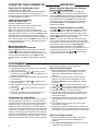
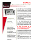
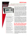
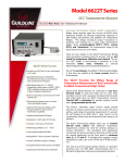
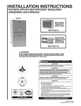
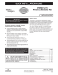
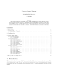
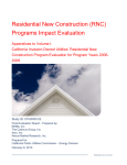
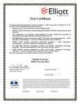
90 Series Blue Single Stage Thermostat with
Automatic Heat/Cool Changeover Option
Installation and Operating Instructions for Model:
Save these instructions for future use!
Model
FAILURE TO READ AND FOLLOW ALL INSTRUCTIONS
CAREFULLY BEFORE INSTALLING OR OPERATING THIS
CONTROL COULD CAUSE PERSONAL INJURY AND/OR
PROPERTY DAMAGE.
1F97-1271
Programming Choices
Non-Programmable 5/1/1 Day
7 Day
APPLICATIONS
THERMOSTAT APPLICATION GUIDE
1F97-1271 Touchscreen Thermostat
Description
Heat Pump (No Aux. or Emergency Heat)
Yes
Heat Pump (with Aux. or Emergency Heat)
No
Standard Heat & Cooling Systems
Yes
Systems requiring more than One Call for Heat or Cool
No
Standard Heat Only Systems
Yes
Millivolt Heat Only Systems – Floor or Wall Furnaces
Yes
Standard Central Air Conditioning
Yes
Gas or Oil Heat
Yes
Electric Furnace
Yes
Hydronic (Hot Water) Zone Heat – 2 Wires
Yes
Hydronic (Hot Water) Zone Heat – 3 Wires
No
SPECIFICATIONS
Electrical Rating Single Stage:
Battery Power . . . . . . . . . . . . . . . . . . . . . . . . .
Input-Hardwire . . . . . . . . . . . . . . . . . . . . . . . .
Terminal Load . . . . . . . . . . . . . . . . . . . . . . . . . . . .
Setpoint Range . . . . . . . . . . . . . . . . . . . . . . . . . . .
Rated Differential (Single Stage) . . . . . . . . . . . . . .
Operating Ambient . . . . . . . . . . . . . . . . . . . . . . . . .
Operating Humidity . . . . . . . . . . . . . . . . . . . . . . . .
Shipping Temperature Range . . . . . . . . . . . . . . . .
Dimensions Thermostat . . . . . . . . . . . . . . . . . . . . .
! CAUTION
To prevent electrical shock and/or equipment damage, disconnect electric power to system at main fuse
or circuit breaker box until installation is complete.
Index
Installation
Wiring Connections
Thermostat Quick Reference
Installer Configuration Menu
Operating Your Thermostat
Programming
Troubleshooting
Page
2
2
3
4
6
6
8
mV to 30 VAC, NEC Class II, 50/60 Hz or DC
20 to 30 VAC
1.0 A per terminal, 1.5A maximum all terminals combined
45 to 99°F (7 to 32°C)
Heat 0.6°F; Cool 1.2°F
32° to +105°F (0 to +41°C)
90% non-condensing max.
-4 to +150°F (-20 to +65°C)
4.6"H x 5.9"W x 1.2"D
ATTENTION: MERCURY NOTICE
This product does not contain mercury. However, this
product may replace a product that contains mercury.
Mercury and products containing mercury must not be
discarded in household trash. Do not touch any spilled
mercury. Wearing non-absorbent gloves, clean up any
spilled mercury and place in a sealed container. For proper
disposal of a product containing mercury or a sealed
container of spilled mercury, place it in a suitable shipping
container and send it to:
White-Rodgers
2895 Harrison Street
Batesville AR 72501
PART NO. 37-6664B
www.white-rodgers.com
Replaces 37-6664A
0616
INSTALLATION
! WARNING
Thermostat installation and all components of the
control system shall conform to Class II circuits per
the NEC code.
Remove Old Thermostat
A standard heat/cool thermostat consists of three basic parts:
1. The cover, which may be either a snap-on or hinge type.
2. The base, which is removed by loosening all captive screws.
3. The switching subbase, which is removed by unscrewing
the mounting screws that hold it on the wall or adapter
plate. Before removing wires from old thermostat,
label each wire with the terminal designation from
which it was attached. Disconnect the wires from the old
thermostat one at a time. Do not let wires fall back into
the wall.
Installing New Thermostat
6. Push excess wire into wall and plug hole with a fire resistant material (such as fiberglass insulation) to prevent
drafts from affecting thermostat operation.
7. Carefully line the thermostat up with the base and snap
into place.
Battery Location
2 "AA" alkaline batteries are included in the thermostat at
the factory with a battery tag to prevent power drainage.
Remove the battery tag to engage the batteries.
To replace batteries, set system to OFF, remove thermostat
from wall and install the batteries in the rear along the top of
the thermostat (see Figure 1).
Figure 1 – Thermostat base and rear view of thermostat
Mounting
Hole
Mounting
Hole
1. Pull the thermostat body off the thermostat base. Forcing
or prying on the thermostat will cause damage to the unit.
Place Level
2. Place base over hole in wall and mark mounting hole
across Mounting Tabs
locations on wall using base as a template.
(for appearance only)
3. Move base out of the way. Drill mounting holes. If you
are using existing mounting holes and the holes drilled
are too large and do not allow you to tighten base snugly, use plastic screw anchors to secure the base.
4. Fasten base snugly to wall using mounting holes shown
in Figure 1 and two mounting screws. Leveling is for
appearance only and will not affect thermostat operation.
5. Connect wires to terminal block on base using
appropriate wiring schematic (see Figures 2 & 3).
Place Level
across Mounting Tabs
(for appearance only)
2 "AA" Batteries
WIRING CONNECTIONS
Refer to equipment manufacturers' instructions for specific
system wiring information. After wiring, see CONFIGURATION section for proper thermostat configuration.
Wiring diagrams shown are for typical systems and describe
the thermostat terminal functions.
TERMINAL DESIGNATION DESCRIPTIONS
Terminal Designation
W .........
G .........
RH . . . . . . . . .
RC . . . . . . . . .
C .........
Description
Heat Relay
Fan Relay
Power for Heating
Power for Cooling
Common wire from secondary side of cooling
system transformer or heat only system transformer
Figure 2 –
Two Transformer System
System
Malfunction
Switch
Low
Voltage
System
Power
Optional (Heat Pump)
Malfunction Indicator
Changeover
Valve Cooling
Changeover
Valve Heating
Compressor
Contactor
L
Figure 3 – Single Transformer System
CLASS II
TRANSFORMER
HEATING
NEUTRAL
24VAC
LINE IN
HOT
W
O
Heat
Relay
B
G
Terminal Designation
Description
L . . . . . . . . . . Heat pump malfunction indicator for
systems with malfunction connection
O . . . . . . . . . Changeover valve for heat pump energized
constantly in cooling
B . . . . . . . . . Changeover valve for heat pump energized
constantly in heating
Y . . . . . . . . . Compressor Relay
Fan
Relay
Y
System
Malfunction
Switch
Low
Optional (Heat Pump)
Voltage
Malfunction Indicator
System
Power
Changeover
Energized in Cooling
O
Changeover
Energized in Heating
B
Compressor
Relay
Y
Heat
Relay
W
Fan
Relay
G
L
RH * Single transformer heat and cool
*
RC
systems require a jumper from
RC to RH for heat only systems.
Attach power to RH. For cool only
attach power to RC.
RH
NOTE: If continuous backlight or hardwired power
input are desired but do not function in both HEAT
and COOL modes, cut the heating transformer 24V
wires and tape off. Connect the neutral circuit
disconnected from the heating transformer to the
neutral circuit of the cooling transformer. Disconnect
the wire to the RH terminal and install a jumper
between RH and RC. Depending on the system
requirements, replace the cooling transformer with a
75VA class II transformer if needed.
2
C
Remove
Jumper
RC
Optional 24VAC
Common
Connection
24 Volt
Common
C
24 Volt
Hot
Optional
Common
Connection
HOT
24VAC
NEUTRAL
CLASS II
TRANSFORMER
COOLING
CLASS II
TRANSFORMER
LINE IN
NOTE: Heat Pump without Aux: If using L for MALF indicator, C
must be connected. Terminals W and Y must be jumpered and CR
HEAT must be selected to SL in Configuration Menu item 6.
LINE IN
THERMOSTAT QUICK REFERENCE
Home Screen Description
Figure 4 – Home Screen Display
Time and Day
Room Temperature and Setting Temperature
(flashes when compressor is in 5 minute lockout)
System button for selecting
Heat/Off/Cool or Auto (Heat/Cool)
Temperature Up/Down
Indicating the current power level
of the 2 "AA" batteries.
Full power remaining.
Half power remaining.
Change
The batteries should
be replaced at this time.
Fan (Auto/On)
Note: If
is displayed, the
thermostat is battery powered.
When battery power remaining
is approximately half,
will
be displayed. If the home is
going to be unoccupied for an
extended period (over 3 months)
and
is displayed, the
batteries should be replaced
before leaving.
Menu for Cleaning, Programming
and Setting Time
Stage 1
Indicates when thermostat is
calling for Heat or Cool
Figure 5 – Programming & Configuration Items
10 11
Programming and Configuration Items
1
Displays and "Keypad Lockout" when in keypad
lockout mode.
Displays and "Temperature Limit" and "Keypad
Lockout" when limited range is activated and locked.
Displays only "Temperature Limit" when limited range
is activated.
2
Indicates period of day being programmed.
3
RUN SCHEDULE (run program) button.
4
SET TIME button or HOLD temperature button.
5
Displays "Change Filter" when the system has run
for the programmed filter time period as a reminder
to change or clean your filter. Displays "Humidifier
Pad" when the system has run for the programmed
filter time period as a reminder to change or clean your
humidifier pad.
6
COPY button or INSTALLER CONFIG button.
7
CLEAN DISPLAY button allows 30 seconds to wipe off
the display or ADVANCE DAY button for programming.
8
Used in programming to set time and in configuration
menu to change selections.
9
"Hold Until" indicates the time when a temporary hold
period will end.
10
"Hours" and "Days" displays during steps in installer
configuration.
9
1
8
14
2
13
12
3
7
6
5
4
11
The words "Hold At" are displayed when the thermostat is in the HOLD mode. "Temporary Hold At" is
displayed when the thermostat is in a temporary HOLD
mode.
12
"Call For Service" indicates a fault in the heating/
cooling system. It does not indicate a fault in the
thermostat.
13
"Stage 1" indicates when heating or cooling stage is
energized.
14
"Copy" indicates the copy program feature is being
used during programming.
3
INSTALLER/CONFIGURATION MENU
To enter the menu: Press the Menu button. Press and hold for 5 seconds the Installer Config button this displays menu item
to advance to the next menu item or
to return to a previous menu item. Press
or
to
#1 in the table below. Press
change a menu item.
NonProgram- Press
mable
Button
Menu
Reference
Number
7
Day
1
1
2
3
4
2
2
3
4
* NA
3
5
6
7
8
9
10
5
6
7
8
9
10
* NA
4
5
6
7
8
11
12
13
11
12
13
9
10
11
14
14
12
15
15
13
16
16
14
1
17
17
15
18
18
16
Displayed
(Factory
Default)
(GAS)
CONFIGURATION MENU
Press
or
to select from
listed options
Comments
ELE
GAS setting: furnace controls blower.
ELE setting: thermostat controls blower.
Days (7)
5, 0
PS (4)
2
Cool, Off,
Cool, Off, Heat,
Heat, Auto Off, Heat, Cool, Off
E (On)
OFF
Cr Heat (FA)
SL
Cr Cool (FA)
SL
CL (OFF)
On
dL (On)
OFF
0
1, 2, 3, 4 HI
(Room temp)
1, 2, 3, 4 LO
°F
°C
b (On)
OFF
Heat (99)
62-99
Cool (45)
45-82
Keypad
L, P
lockout (L)
Temperature Limit
Keypad
On
lockout (OFF)
000
000 to 999
000 Change
Filter (OFF)
200 hours
Change
Humidifier
(OFF)
100 hours
On
Selects programming option.
Selects programming periods per day.
Selects system switch configuration for heat and cool with
Auto changeover, Heat & Cool, Heat Only or Cool Only.
Selects Energy Management Recovery on or off.
Selects Heat cycle rate Fast (FA) or Slow (SL).
Selects Cool cycle rate Fast (FA) or Slow (SL).
Selects Compressor lockout ON or OFF.
Selects display light on or off.
Selects temperature display adjustment 1, 2, 3 or 4 degrees
high or low.
Selects Fahrenheit or Celsius temperature display.
Selects beeper on or off.
Selects highest Heat setpoint temperature.
Can select 62° to 99°F.
Selects lowest Cool setpoint temperature.
Can select 45° to 82°F.
Selects keypad lockout full or partial to be set.
Activates temperature limit ranges.
Selects keypad lockout on or off.
Selects keypad lockout combination number if lockout is on.
000 is not a valid selection.
Select change filter alert time period.
25 to 1975 hours
On
When set ON, selects time in 25 hour increments.
Selects change humidifier pad alert time period
25 to 1975 hours
When set ON, selects time in 25 hour increments.
* Not Applicable
1) GAS or Electric (ELE) fan operation. If the heating system
requires the thermostat to energize the fan, select ELE.
Select GAS if the heating system energizes the fan on a
call for heat. Note: Resetting the thermostat switches the
option to ELE.
2) This control can be configured for 7 independent day or
5/1/1 programming or non-programmable mode. The
display indicates "7 Days" as default. The programs per
week can be toggled to "5 Days" or "0 Days" by pressing
or
keys. A selection of 0 Days for non-programthe
mable will eliminate the need for EMR, and that step
in the menu will be skipped.
3) Programmable Periods – This control can be configured
for 4 or 2 programmable periods per day. The display
indicates "4 PS" in the display as default. The programor
mable periods can be toggled by pressing the
keys.
4
4) System Switch Configuration – This thermostat is
configured for Heat and Cool with Auto changeover
(SYSTEM switch with Cool Off Heat Auto) default. It can
also be configured for Heat and Cool (Cool Off Heat),
Heat only (Off Heat), and Cool only (Cool Off).
5) Energy Management Recovery – (this step is skipped if
configured to be non-programmable).
Energy Management Recovery (E) On causes the
thermostat to start heating or cooling early to make the
building temperature reach the program setpoint at the
time you specify. Heating will start 5 minutes early for
every 1° of temperature required to reach setpoint.
Example: E On is selected and your heating is programmed to 65° at night and 70° at 7 AM. If the building
temperature is 65°, the difference between 65° and 70° is
5°. Allowing 5 minutes per degree, the thermostat setpoint will change to 70° at 6:35 AM. Cooling allows
more time per degree, because it takes longer to reach
temperature.
INSTALLER/CONFIGURATION MENU
6 & 7) Fast or Slow Cycle Selection – The factory default
setting for Heat is fast cycle (FA), which cycles heat at
approximately 0.6°F. If you prefer slow cycle, press the
or
key to change to SL. Heat will cycle at approximately 1.2°F. For Cool the default setting is fast cycle
(FA), which cycles cool at approximately 1.2°F. If you
or
key to change to SL,
prefer slow cycle, press the
cool will cycle at approximately 1.7°F.
8) Select Compressor Lockout CL OFF or ON – Selecting
CL ON will cause the thermostat to wait 5 minutes between cooling cycles. This is intended to help protect the
compressor from short cycling. Some newer compressors already have a time delay built in and do not require
this feature. Your compressor manufacturer can tell you if
the lockout feature is already present in their system.
When the thermostat compressor time delay occurs, it
will flash the setpoint for up to five minutes.
When CL is ON and 24V common (C) is connected, the
lockout feature will prevent compressor start after a 24V
power interruption of less than 5 minutes. This will
assure a 5-minute delay to prevent premature compressor failure.
9) Select Backlight Display – The display backlight
improves display contrast in low lighting conditions.
When the C terminal is powered, selecting backlight (dL
ON) will turn the light on continuously. Selecting backlight
OFF will turn the light on momentarily after any key is
pressed. When the C terminal is not powered, this
selection has no effect.
10) Select Temperature Display Adjustment 4 LO to 4 HI
Allows you to adjust the room temperature display up to
4° higher or lower. Your thermostat was accurately calibrated at the factory, but you have the option to change
the display temperature to match your previous thermostat. The current or adjusted room temperature will be
displayed on the left side of the display.
11) Select F° or C° Readout – Changes the display readout
to Centigrade or Fahrenheit as required.
12) Select Audio Prompting (Beeper) On or Off – Default
setting is On (On b) if you wish to turn off the beeper
select Off b.
13) Heat Temperature Limit Range – This feature adjusts
the highest setpoint temperature for heat. The default
setting is 99°F. It can be changed between 62°F and
or
key. The "temperature
98°F by pressing the
limit" icon will be displayed to the left of your setpoint
temperature when using this feature. The "temperature
limit" icon will flash if an attempt is made to adjust the
temperature beyond the range selected.
14) Cool Temperature Limit Range – This feature adjusts
the lowest setpoint temperature for cool. The default
setting is 45°F. It can be changed between 46°F and
or
key. The "temperature
82°F by pressing the
limit" icon will be displayed to the left of your setpoint
temperature when using this feature. The "temperature
limit" icon will flash if an attempt is made to adjust the
temperature beyond the range selected.
15) Keypad Lockout – This step allows you to select the
type of lockout or limited range security required. If no
to
lockout or limited range security is required, press
advance the menu.
Three security settings are available in this menu item.
or
keys to select the lockout desired.
Use the
Lockout selections are:
"Keypad Lockout and L" = Total Lockout. Total Lockout
locks all keys.
"Keypad Lockout and P" = Partial Lockout. Partial Lockor
keys to operate within your
out allows only the
set temperature limits.
"Temperature Limit/Keypad Lockout" prevents
changing the temperature limits in the Configuration
Menu.
16) Keypad Lockout Combination Number Selection
Display will read "OFF" "Keypad Lockout".
Skip this step and continue through the configuration
menu items 17 and 18 if you require an Air Filter Change
out indicator or Humidifier Pad Change out indicator by
button to advance.
pressing the
Return to this point when you are ready to start your
selected lock-out and continue by:
or
keys to select ON.
Pressing
Press . Display will read "000".
or
keys to select your keypad lockout
Pressing
combination number. Note: "000" is not a valid
combination choice.
Record the number you select for future use.
to exit the menu. The security feature you
Press
select will start in 10 seconds. The system button will
remain active for 10 seconds to allow setting Heat, Off,
Cool or Auto.
17) Select Filter Replacement Run Time – The thermostat
will display "Change Filter" after a set time of blower
operation. This is a reminder to change or clean your air
filter. This time can be set from 25 to 1975 hours in 25
hour increments. A selection of OFF will cancel this
feature. When "Change Filter" is displayed, you can
clear it by pressing Clean Display. In a typical application,
200 hours of run time is approximately 30 days.
18) Select Humidifier Pad Replacement Run Time – The
thermostat will display "Change Humidifier Pad" after a
set time of humidifier operation. This is a reminder to
change or clean your humidifier pad. This time can be set
from 25 to 1975 hours in 25 hour increments. A selection
of OFF will cancel this feature. When "Change Humidifier Pad" is displayed, you can clear it by pressing Clean
Display. Check with your humidifier manufacturer for a
recommended maintenance interval.
5
OPERATING YOUR THERMOSTAT
Choose the Fan Setting (Auto or On)
Set the FAN Switch to Auto or On.
Fan Auto is the most commonly selected setting and runs
the fan only when the heating or cooling system is on.
Fan On runs the fan continuously for increased air circulation
or to allow additional air cleaning.
Choose the System Setting
(Heat, Off, Cool, Auto)
Press the SYSTEM button to select:
Heat: Thermostat controls only the heating system.
Off: Heating and Cooling systems are off.
Cool: Thermostat controls only the cooling system.
Auto: Auto Changeover is used in areas where both heating
and cooling may be required on the same day. AUTO allows
the thermostat to automatically select heating or cooling
depending on the indoor temperature and the selected heat
and cool temperatures. When using AUTO, be sure to set the
Cooling temperatures more than 1° Fahrenheit higher than
the heating temperature.
Manual Operation for
Non-Programmable Thermostats
Press the SYSTEM button to select Heat or Cool and use
or
buttons to adjust the temperature to your
the
desired setting. After selecting your desired settings you can
also press the SYSTEM button to select AUTO to allow
the thermostat to automatically change between Heat and
Cool.
IMPORTANT!
Manual Operation (Bypassing the Program)
Programmable Thermostats
Press
or
and the HOLD button, then adjust the
temperature wherever you like. This will override the program. The HOLD feature bypasses the program and allows
you to adjust the temperature manually, as needed. Whatever temperature you set in HOLD will be maintained 24
hours a day, until you manually change the temperature or
press Run Schedule to cancel HOLD and resume the
programmed schedule.
Program Override (Temporary Override)
Press
or
buttons to adjust the temperature. This will
override the temperature setting for a (default) four hour
override period. The override period can be shortened by
or lengthened by pressing . Program Override
pressing
period can range from 15 minutes to 7 days.
Example: If you turn up the heat during the morning program, it will be automatically lowered later, when the temporary hold period ends. To cancel the temporary setting at any
time and return to the program, press Run Schedule.
If the SYSTEM button is pressed to select AUTO the
thermostat will change to Heat or Cool, whichever ran last. If
it switches to heat but you want cool, or it changes to cool
and
buttons simultabut you want heat, press both
neously to change to the other mode.
PROGRAMMING
Set Current Time and Day
Fill in the blank schedule on the next page then:
1) Press Menu and then Set Time button once. The display
will show the hour only.
or
key until you reach
2) Press and hold either the
the correct hour and AM/PM designation (AM begins at
midnight, PM begins at noon).
3) Press Set Time once again. The display window will show
the minutes only.
or
key until you reach
4) Press and hold either the
the correct minutes.
5) Press Set Time once again. The display will show the day
of the week.
or
key until you reach the current day
6) Press the
of the week.
7) Press Run Schedule once. The display will show the
correct time and room temperature alternately.
Enter the Heating Program
Programming Tip: Copy Button
You may copy any daily program to another day or group of
days by pressing the Copy button. In 7 day programming
mode when the Copy button is pressed, the other 6 days of
the week will flash. To copy the current program into the
remaining six days, simply press the Copy button again. To
copy the current program to another day of the week, press
Advance Day to select the day and press Copy to paste the
program. In 5/1/1 day programming mode the copy function
is similar. The weekday (Mon-Fri) program can be copied to
Sat and Sun (both flashing) or use Advance Day to choose
Sat or Sun and press the Copy button to paste the program.
6
1) Press the Menu button and then press Set Schedule.
Press SYSTEM button to select "Heat" in the system
switch area indicating the active mode being programmed.
2) The top of the display will show the day(s) being programmed. The time and set at temperature are also
displayed. "Morning" will also be displayed to indicate
the period.
or
key to change the temperature to your
3) Press
selected temperature for the 1st heating period (Morning).
4) Press
or
key to adjust the start time for period.
5) The time will change in 15 minute increments.
6) After you have set the time and the temperature for the
period to begin, press Set Schedule to advance to the
next program period.
7) Repeat steps 2 through 6 until all of the program times
and temperatures are set for all program periods on
that day.
8) Press "Advance Day" to change to the next day and
repeat steps 2 through 8.
9) When programming is complete and all of the times and
temperatures match your desired heating schedule, press
Run Schedule. The thermostat will now run your program.
Enter the Cooling Program
1) Press SYSTEM button to select "Cool" in the system
switch area indicating the active mode being programmed.
2) Follow Enter Heating Program instructions for entering
cooling times and temperatures.
PROGRAMMING
Energy Saving Factory Pre-Program
The 1F97-1271 thermostats are programmed with the energy saving settings shown in the table below for all days of the
week. If this program suits your needs, simply set the thermostat clock and press the RUN button.
The table below shows the factory set heating and cooling schedule for all days of the week.
* Wake Up
(Morning)
Heating
Program
Cooling
Program
Leave For Work
(Day)
* Return Home
(Evening)
Go To Bed
(Night)
6:00 AM
70°F
8:00 AM
62°F
5:00 PM
70°F
10:00 PM
62°F
6:00 AM
78°F
8:00 AM
85°F
5:00 PM
78°F
10:00 PM
82°F
* You can eliminate these two program periods in the configuration menu (reference #3) if the building is occupied all day.
Day will change to 6:00 am and can be programmed as required.
Planning Your Program – Important
The Heating and Cooling Program schedules below allow you to pencil in your own program times and temperatures.
The 1F97-1271 comes configured for 7 day programming and can also be configured for 5+1+1 programming (see configuration section).
Factory settings are listed on Monday, Saturday and Sunday. If you are re-programming a 5+1+1 day schedule, pencil in your
own times and temperatures directly below the factory times and temperatures.
If you are re-programming a 7 day fill in all lines with the times and temperatures you want.
Keep the following guidelines in mind when planning your program.
• In Heating, lower temperatures will save energy.
• In Cooling, higher temperatures will save energy.
• If you plan on using Auto Changeover, do not program the heating higher than the cooling.
Worksheet for Re-Programming 5+1+1 and 7 Day Program
Heating
Program
Wake Up
(Morning)
Leave For Work
(Day)
Return Home
(Evening)
Go To Bed
(Night)
6:00 AM
70°F
8:00 AM
62°F
5:00 PM
70°F
10:00 PM
62°F
SAT
6:00 AM
70°F
8:00 AM
62°F
6:00 PM
70°F
10:00 PM
62°F
SUN
6:00 AM
70°F
8:00 AM
62°F
6:00 PM
70°F
10:00 PM
62°F
MON
TUE
WED
THU
FRI
Cooling
Program
Wake Up
(Morning)
Leave For Work
(Day)
Return Home
(Evening)
Go To Bed
(Night)
6:00 AM
78°F
8:00 AM
85°F
5:00 PM
78°F
10:00 PM
82°F
SAT
6:00 AM
78°F
8:00 AM
85°F
5:00 PM
78°F
10:00 PM
82°F
SUN
6:00 AM
78°F
8:00 AM
85°F
5:00 PM
78°F
10:00 PM
82°F
MON
TUE
WED
THU
FRI
7
TROUBLESHOOTING
Reset Operation
If a voltage spike or static discharge blanks out the display or causes erratic thermostat operation, you can reset the thermostat by removing
the wires from terminals R and C (do not short them together) and removing batteries for 2 minutes. After resetting the thermostat, replace
the wires and batteries. If the thermostat has been reset and still does not function correctly contact your heating/cooling service person or
place of purchase.
To reset the programming, clock and configuration settings, press
and
and the SYSTEM button simultaneously. The thermostat
should go blank and then all segments will be displayed momentarily.
Symptom
Possible Cause
Corrective Action
No Heat/No Cool/No Fan
(common problems)
1. Blown fuse or tripped circuit breaker.
2. Furnace power switch to OFF.
3. Furnace blower compartment door or
panel loose or not properly installed.
4. Loose connection to thermostat or system.
Replace fuse or reset breaker.
Turn switch to ON.
Replace door panel in proper position to engage safety
interlock or door switch.
Tighten connections.
No Heat
1. Pilot light not lit.
2. Furnace Lock-Out Condition. Heat
may also be intermittent.
Re-light pilot.
Many furnaces have safety devices that shut down when a
lock-out condition occurs. If the heat works intermittently
contact the furnace manufacturer or local HVAC service
person for assistance.
Diagnostic: Set SYSTEM Switch to HEAT and raise the
setpoint above room temperature. Within a few seconds
the thermostat should make a soft click sound. This sound
usually indicates the thermostat is operating properly. If
the thermostat does not click, try the reset operation listed
above. If the thermostat does not click after being reset
contact your heating and cooling service person or place
of purchase for a replacement. If the thermostat clicks,
contact the furnace manufacturer or a HVAC service
person to verify the heating is operating correctly.
3. Heating system requires service or
thermostat requires replacement.
No Cool
1. Cooling system requires service or
thermostat requires replacement.
Same as diagnostic for No Heat condition except set the
thermostat to COOL and lower the setpoint below the
room temperature. There may be up to a five minute delay
before the thermostat clicks in Cooling.
Heat, Cool or Fan
Runs Constantly
1. Possible short in wiring.
2. Possible short in thermostat.
3. Possible short in heat/cool/fan system.
4. FAN Switch set to Fan ON.
Check each wire connection to verify they are not shorted
or touching together. No bare wire should stick out from
under terminal block. Try resetting the thermostat as
described above. If the condition persists the manufacturer
of your system or service person can instruct you on how
to test the Heat/Cool system for correct operation. If the
system operates correctly, replace the thermostat.
Thermostat Setting &
Thermostat Thermometer
Disagree
1. Thermostat thermometer setting
requires adjustment.
The thermometer can be adjusted +/- 4 degrees. See
Temperature Display Adjustment in the Configuration
Menu section.
Furnace (Air Conditioner)
Cycles Too Fast or Too Slow
(narrow or wide
temperature swing)
1. The location of the thermostat and/or
the size of the Heating System may
be influencing the cycle rate.
Digital thermostats provide precise control and cycle faster
than older mechanical models. The system turns on and
off more frequently but runs for a shorter time so there is
no increase in energy use. If you would like an increased
cycle time, choose SL for slow cycle in the Configuration
menu, step 6 (heat) or 7 (cool). If an acceptable cycle rate
is not achieved, contact a local HVAC service person for
additional suggestions.
Press the Menu button (button will disappear) and hold in
for 15 to 20 seconds. This unlocks the thermostat.
Forgot Keypad
Lockout Code
HOMEOWNER HELP LINE: 1-800-284-2925
White-Rodgers is a division
of Emerson Electric Co.
The Emerson logo is a
trademark and service mark
of Emerson Electric Co.
St. Louis, Missouri
www.white-rodgers.com