1
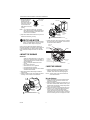
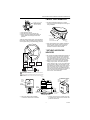
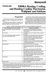
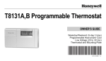
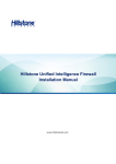
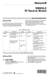
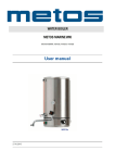
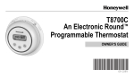
The Round® Creative Series
Y460A2003 Thermostat
INSTALLATION MANUAL
The Y460A2003 Thermostat is for 15 to 30 Vac control
of gas- or oil-fueled warm air, steam or hot water
heating/electric cooling systems.
Your Y460A Thermostat
❑ Follow these instructions step-by-step for proper
installation of your Honeywell thermostat. It is
recommended that as you read, understand and
complete each step, you check √ it off with a pencil
or pen.
1 PREPARE FOR INSTALLATION
❑ Assemble the following required tools:
Flat-bladed screwdriver; hand or power drill with
3/16 in. (4.8 mm) drill bit; wire cutter/stripper or sharp
knife; bubble level or plumb bob and line.
FLAT BLADE
SCREWDRIVER
HAND OR POWER
DRILL WITH 1/16 INCH
DRILL BIT, IF NEEDED TO
DRILL HOLES IN WALL
WIRE CUTTER/STRIPPER OR SHARP
KNIFE, IF NEEDED TO STRIP WIRES
MASKING TAPE, IF NEEDED
TO LABEL WIRES AS THEY
ARE DISCONNECTED FROM
OLD THERMOSTAT
SPIRIT LEVEL OR PLUMB BOB AND LINE TO LEVEL
THERMOSTAT FOR ACCURATE OPERATION
M 835
IMPORTANT:
For cooling systems, do not operate cooling if
outdoor temperature is below 50°F (10°C).
❑ Test your heating and/or cooling systems to be sure
they are working, especially if they have been
inoperative for any length of time. If either system
does not work, contact your local heating/air
conditioning dealer for assistance.
® U.S. Registered Trademark
Copyright © 1999 Honeywell Inc. •
•All Rights Reserved
IMPORTANT:
Turn off power to the system at the main fuse
or circuit breaker panel. Most buildings have a
separate switch box or circuit breaker for disconnecting power to the furnace.
2 UNPACK YOUR THERMOSTAT
❑ Carefully unpack your new thermostat.
❑ Remove and discard the shipping wrap; be sure to
save the screws and the instructions.
❑ Remove the thermostat cover and set it aside to use
later.
❑ Remove the red plastic insert that holds the mercury
switch in place.
3 REMOVE YOUR OLD
THERMOSTAT
❑ Remove the cover of the old thermostat. If the cover
does not snap off when pulled firmly from the
bottom, look for screw(s) to loosen to unlock the
cover.
❑ Before removing
the old thermostat
from the wall, look
BULB
SWITCH
at it carefully to
locate the heat
anticipator
ANTICIPATOR
adjustment
SCALE
mechanism. Look
at the illustration to
help you recognize
ANTICIPATOR
M6115
SETTING LEVER
the heat
anticipator. Make a
note here ______________ of that anticipator
setting for use in Step 7. The heat anticipator pointer,
if adjustable, will be set at one of a series of numbers
representing the electrical current rating of the
primary control in your furnace: .2, .4, .8, etc or 0.2,
0.4, 0.8, etc. If no heat anticipator/indication is
showing, go on to the next step.
❑ Loosen screw(s) holding the thermostat base to the
subbase or wall and lift it away.
69- 1358
THE ROUND® CREATIVE SERIES Y460A2003 THERMOSTAT
❑ Disconnect wires from
the old thermostat or
subbase. Wrap the
wires around a pencil or
other object, as shown,
to prevent them from
falling back into the wall
opening.
WIRES THROUGH
WALL OPENING
OUTLET BOX
Q539 1
SUBBASE
M5136
Y460
NOTE: As you disconnect each wire, use masking
tape to tape the end and label with the letter of
the terminal designation to allow easier reconnection to the new subbase.
CAPTIVE
MOUNTING
SCREWS (3)
❑ Keep the old thermostat for reference until your new
thermostat is functioning correctly.
1
RECYCLING NOTICE
If this control is replacing a control that contains
mercury in a sealed tube, do not place your old
control in the trash. Dispose of it properly.
Contact your local waste management authority for
instructions regarding recycling and the proper disposal
of the old thermostat. If you have questions, call the
Honeywell Customer Response Center at 1-800-4681502.
THERMOSTAT
CABLE
ENTRANCE
HOLE
USE Q539 SUBBASE FOR HEAT AND/OR COOL
APPLICATIONS WITH SWITCHING.
M13417
❑ Tighten the screws after using a spirit level or plumb
line to accurately level the subbase. It must be level
to maintain accurate calibration.
PLUMB LINE
MARKERS
MOLDED
POST (2)
SPIRIT
LEVEL
4 MOUNT THE SUBBASE
IMPORTANT:
Install your thermostat about 5 ft (1.5m) above
the floor in an area with good air circulation at
average temperature. Do not install it where it
may be affected by:
— drafts, or dead spots behind doors and in
corners.
— hot or cold air from ducts.
— radiant heat from sun or appliances.
— concealed pipes and chimneys.
— unheated (uncooled) areas such as an outside
wall behind the thermostat.
❑ Bring the thermostat cable through the subbase
entrance hole.
❑ Fasten the subbase to the wall or outlet box with the
mounting screws as shown in the illustration.
WALL
Y460
THERMOSTAT
CABLE
ENTRANCE
HOLE
CAPTIVE
MOUNTING
SCREWS (3)
MOUNTING
HOLE (3)
M13415
5 WIRE THE SUBBASE
❑ Follow the instructions provided by the heating or
heating/cooling equipment manufacturer. If not
available, refer to the thermostat wiring diagram.
NOTE: All wiring must comply with local electrical
codes and ordinances.
USE Q539 SUBBASE FOR HEAT AND/OR COOL
APPLICATIONS WITH SWITCHING.
❑ Refer to the illustration to strip the thermostat wire
insulation from the wire where it connects to the
terminal, as necessary.
❑ Refer to the labels you placed on the wires when you
removed the old thermostat. Match the letter of your
old thermostat wire with the corresponding terminal
letter on your new thermostat.
❑ Connect the wires to the matching terminals on the
subbase. If your old thermostat had an R terminal,
and your new one has RC and RH terminals,
connect the old wire R to terminal RH, and add a
small piece of wire to use as a jumper to connect RC
to RH. The drawing shows how to jumper RC to RH.
M13416
69-1358
MOUNTING
SLOT (3)
Wire the Subbase
Q539 1
SUBBASE
1
OPENING FOR
THERMOSTAT
WIRING (PLUG)
(WITH INSULATION)
2
THE ROUND® CREATIVE SERIES Y460A2003 THERMOSTAT
6 MOUNT YOUR THERMOSTAT
G
RH
EXAMPLE: FOR RC TO RH
JUMPER, STRIP WIRE
END LONG ENOUGH TO
JOIN BOTH TERMINALS.
RC
❑ Set the heat anticipator indicator to 1.2 before
mounting to prevent the anticipator from burning out
during installation.
Y
M1277A
W
1.0
.8
❑ Firmly tighten the screws.
❑ Push the excess wire back into the wall.
❑ Plug the hole with nonflammable insulation to
prevent drafts from affecting the thermostat
operation.
FA
N
AT
.5
.4
.3
SCALE
.2
.15
.12
LONGER
HOLE SUITABLE FOR
PENCIL POINT
TO MOVE INDICATOR
Y460A for heating/cooling system using separate RCRH terminals. If old thermostat has single R terminal,
refer to jumper drawing in Subbase Wiring procedure.
HEAT
ANTICIPATOR
INDICATOR
M1368
❑ Align the thermostat over the subbase and tighten
the three captive mounting screws (see Step 4).
These captive mounting screws complete the
electrical connections to the thermostat.
ON
OF
F
HE
.6
TO
CO
OL
AU
7 SET HEAT ANTICIPATOR
INDICATOR
RH G
R
C
❑ Be sure the thermostat adjustable heat anticipator is
set correctly to accurately control the temperature.
An incorrect setting (if too high) can result in wide
room temperature swings or (if too low) burn out the
anticipator, which voids the thermostat warranty.
❑ Make sure you have the current draw (anticipator
setting) for your system. This is the number you
wrote in the box in Step 3. If you were unable to find
the current draw for Step 3, this information can be
found printed on the primary control at the furnace or
boiler. The primary control is usually a gas valve, a
relay or burner control box, Aquastat® Controller or
zone valve with the thermostat wires connected to it.
These controls are usually located behind the
furnace cover; see the illustration.
Y
W
2
FAN
RELAY
HEATING
RELAY OR
VALVE COIL
COOLING
CONTACTOR
COIL
1
1
1
POWER SUPPLY. PROVIDE DISCONNECT MEANS AND OVERLOAD
PROTECTION AS REQUIRED.
2
IN HEATING, THE FAN IS CONTROLLED BY ANOTHER CONTROLLER,
SUCH AS A HONEYWELL L4064 FAN AND LIMIT CONTROLLER OR
FAN TIMER.
M13418
OIL BURNER CONTROL
8406
V8043E 1004 4
24V 50/60CY
.32 AMP @ 60CY
SHOWS
VOLTAGE
RATING
0
A
P
M
A
SHOWS
VOLTAGE
RATING
TO
BURNER
C
.2
0
V
SHOWS
ANTICIPATOR
SETTING
SHOWS
CURRENT
DRAW
3
SHOWS
VOLTAGE
RATING
T
T
F
24 Vac 50/60 Hz
F
0.4 AMP
SHOWS
ANTICIPATOR
SETTING
FROM MAIN
FUEL SUPPLY
ZONE VALVE
TYPICAL GAS VALVE
❑ If the current rating is still unavailable:
— Remove the W wire from the subbase.
M6116B
— Connect one probe of an ac ammeter (0 to 2.0A,
for example) to the W wire and connect the other
probe to the W terminal.
3
69-1358
THE ROUND® CREATIVE SERIES Y460A2003 THERMOSTAT
— Let the system operate through the ammeter for
at least one minute before taking a reading.
Record the reading here ______________ .
— Reconnect the W wire to the W terminal.
❑ Move the heat anticipator indicator to match the
number you recorded in Step 3 or in Step 7.
NOTE: Hot water and steam systems require you to
multiply the current rating times 1.3. For electric heat systems, add the fan relay current,
usually 0.2A to 0.4A.
❑ Snap the cover ring over the thermostat dial.
9 CHECK OUT THE SYSTEM
Heating
❑ Turn down the temperature setting to the lowest
point. Move the System switch to Heat. Raise the
temperature setting above room temperature; the
heating equipment should start. Lower the
temperature setting below room temperature; the
heating system should stop.
Cooling
CAUTION
8 SET THE TEMPERATURE
Equipment Damage Hazard.
Can cause permanent damage to the
compressor or other equipment.
To avoid possible compressor damage, allow
the compressor to remain off for five minutes
before restarting.
❑ Turn the transparent dial until the desired point on
the setting scale is aligned with the pointer, as shown
in the illustration.
IMPORTANT:
During a call for heat or cool, an electrical
spark can be seen through the colored
decorator cover ring. Do not be alarmed;
this is normal operation for a mercury
switch.
To avoid possible equipment damage, do not
operate cooling when the outside temperature is
below 50°F (10°C).
See equipment manufacturer instructions.
Set Subbase Switch
CAUTION
Equipment Damage Hazard.
Can cause permanent damage to the
compressor.
Do not rotate the thermostat dial back and forth
just to observe the electrical spark; observe the
compressor five-minute minimal-off period.
CAUTION
Equipment Damage Hazard.
Can cause permanent damage to the
compressor.
Do not rotate the thermostat dial back and forth
just to observe the electrical spark; observe the
compressor five-minute minimal-off period.
❑ To operate the heating system, set the subbase
System switch to Heat. To operate the cooling
system, set the subbase System switch to Cool. Set
it to Off if you want neither heating or cooling.
❑ Set the Fan switch to On for continuous fan
operation or to Auto for fan operation during heating
or cooling cycles.
70
8
0
5
60
WARRANTY
Honeywell warrants this product, excluding battery, to be free
from defects in the workmanship or materials, under normal
use and service, for a period of one (1) year from the date of
purchase by the consumer. If, at any time during the warranty
period, the product is defective or malfunctions, Honeywell
shall repair or replace it (at Honeywell’s option) within a reasonable period of time.
TEMPERATURE
SETTING
0
❑ Turn up the temperature setting to the highest point.
Move the subbase System switch to Cool. Lower the
temperature setting below the room temperature; the
cooling equipment should start. Raise the temperature setting above the room temperature; the cooling
system should stop.
If the product is defective,
i.
5
0
0
60
70
8
ii.
THERMOMETER
M13419
return it, with a bill of sale or other dated proof of purchase, to the retailer from which you purchased it, or
package it carefully, along with proof of purchase
(including date of purchase) and a short description of
the malfunction, and mail it, postage prepaid, to the following address:
Honeywell Inc.
Return Goods Department
1050 Berkshire Lane
Plymouth, MN 55441-4437
This warranty does not cover removal or reinstallation costs.
This warranty shall not apply if it is shown by Honeywell that
the defect or malfunction was caused by damage which
occurred while the product was in the possession of a
consumer.
69-1358
4
THE ROUND® CREATIVE SERIES Y460A2003 THERMOSTAT
Honeywell’s sole responsibility shall be to repair or replace the
product within the terms stated above. HONEYWELL SHALL
NOT BE LIABLE FOR ANY LOSS OR DAMAGE OF ANY
KIND, INCLUDING ANY INCIDENTAL OR CONSEQUENTIAL
DAMAGES RESULTING, DIRECTLY OR INDIRECTLY, FROM
ANY BREACH OF ANY WARRANTY, EXPRESS OR
IMPLIED, OR ANY OTHER FAILURE OF THIS PRODUCT.
Some states do not allow the exclusion or limitation of incidental or consequential damages, so this limitation may not apply
to you.
THIS WARRANTY IS THE ONLY EXPRESS WARRANTY
HONEYWELL MAKES ON THIS PRODUCT. THE DURATION
OF ANY IMPLIED WARRANTIES, INCLUDING THE WARRANTIES OF MERCHANTABILITY AND FITNESS FOR A
PARTICULAR PURPOSE, IS HEREBY LIMITED TO THE
ONE YEAR DURATION OF THIS WARRANTY. Some states
do not allow limitations on how long an implied warranty lasts,
so the above limitation may not apply to you.
This warranty gives you specific legal rights, and you may have
other rights which vary from state to state.
If you have any questions concerning this warranty, please
write our Customer Assistance Center, Honeywell Inc., P.O.
Box 524, Minneapolis, MN 55440-0524 or call 1-800-4681502, Monday-Friday, 7:00 a.m. to 5:30 p.m., Central time. In
Canada, write Retail Products ON15-02H, Honeywell Limited/
Honeywell Limitée, 155 Gordon Baker Road, North York,
Ontario M2H 3N7.
5
69-1358
Home and Building Control
Honeywell Inc.
Honeywell Plaza
P.O. Box 524
Minneapolis, MN 55408-0524
69-1358
G.H. 12-99
Printed in Mexico
Home and Building Control
Honeywell Limited-Honeywell Limitée
155 Gordon Baker Road
North York, Ontario
M2H 3N7
www.honeywell.com