1
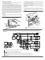
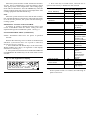
T8631A,R Communicating
Chronotherm III Thermostats
Application
T8631A,R can be connected to Honeywell's TotalHome
system for external access and control. TotalHome system
devices communicate using HBus, a Honeywell communications protocol.
These thermostats, powered directly from the control
transformer, provide energy saving control for a 24 Vac
conventional heating/cooling or multistage heat pump
heating/cooling system as indicated in Table 1.
As long as AC power is continuously available to the
transformer, the thermostat will be compatible with most
control systems.
The T8631A,R models include a SYSTEM LED near
the top of the thermostat face. The SYSTEM LED lights
when the thermostat is signaling for heating or cooling.
T8631R includes AUX. HT. and EM. HT LEDs near the
bottom center of the subbase. The AUX. HT. LED lights
whenever the thermostat is calling for operation of the
backup or auxiliary heater. Backup (auxiliary) heat is more
expensive to operate than the heat pump and typically is
used only when the heat pump is unable to handle the load.
The EM. HT. LED lights whenever the thermostat system
switch is in the EM. HT. position. The EM.HT. LED may
also light on some systems if the heat pump is malfunctioning. The system switch needs to be moved to EM.HT. on
these heat pumps.
Heat and cool anticipation is fixed in both models; no
adjustment is necessary. T8631A has adjustable cycle rate
for heating; T8631R cycle rate is adjustable only for
auxiliary heat.
TABLE I—THERMOSTAT MODELS.
Stages
Thermostat
T8631A
T8631R
Heat
1
2
Cool
1
1
Switching
System
Fan
HEAT-OFF-COOL
ON-AUTO
EM. HT.-HEAT-OFF-COOL
ON-AUTO
Installation
WHEN INSTALLING THIS PRODUCT…
1. Read these instructions carefully. Failure to follow
them could damage the product or cause a hazardous
condition.
2. Check the ratings on the product to make sure the
product is suitable for your application.
3. Installer must be a trained, experienced service technician.
4. After installation is complete, check out product
operation as provided in these instructions.
5. Allow thermostat to warm to room temperature
before operating.
IMPORTANT: After wiring is complete, push excess wire
back into the hole, and plug hole with nonhardening
caulk, putty or insulation to prevent drafts from
affecting thermostat operation.
LOCATION
Install thermostat and subbase about 5 ft [1.5 m] above
the floor in an area with good air circulation at room
temperature.
Do not install the thermostat where it may be affected by:
— drafts or dead spots behind doors, in corners or under
cabinets.
— hot or cold air from ducts.
— radiant heat from sun or appliances.
— concealed pipes and chimneys.
Program
5-1-1
5-1-1
— unheated (uncooled) areas behind the thermostat,
such as an outside wall.
WIRING TO HEATING/COOLING SYSTEM
The T8631 requires connection to both sides of the
heating transformer secondary for power.
If Replacing An Existing Thermostat
Turn off power to thermostat at furnace or heat pump.
A two-transformer system may require turning off two
switches or disconnects. Remove any existing wallplate or
subbase from wall. Label each wire with, or write down,
the letter or number on the wiring terminal as the wire is
removed, to avoid miswiring later.
If New Installation
Run cable to a hole at the selected wall location, and
pull about 3 in. [76 mm.] of wire through the opening.
Color-coded, 18-gauge thermostat cable with one conductor for each wiring terminal, excluding H terminals, is
recommended. Good service practice recommends selecting cable with one or two more conductors than the
immediate application requires.
WIRING TO TOTALHOME SYSTEM
The HBus connection requires an unshielded cable with
3 twisted pairs of #22 AWG solid wire. Use Belden #8742,
Alpha #1304 or equivalent wire. Route this cable with the
thermostat cable to the utility room. Do not connect the
HBus cable to the T8631 until the other TotalHome devices
are connected.
J.H . • Rev. 3-93 • © Honeywell Inc. 1993 • Form Number 69-0689—2
MOUNTING SUBBASE
The subbase does not require leveling for proper operation, but only for appearance.
Remove thermostat from subbase. See Fig. 1.
The subbase mounts directly onto the wall with the
screws and anchors included in the package. Use the
subbase as a template, and with a pencil, mark the two
mounting screw positions. See Fig. 2. If drywall construction, plastic anchors must be used; select 3/16 in. bit to
drill holes for anchors. Gently tap anchors into holes until
they are flush with the wall surface. Thread wires through
the center opening of the subbase. Then, mount the subbase
by using two screws provided. Gently tighten screws, level
top surface of subbase and then securely tighten screws.
Disconnect power before wiring to prevent electrical
shock or equipment damage.
The shape of the terminal barrier permits insertion of
straight or conventional wraparound wiring connections.
Either method is acceptable.
Refer to Figs. 3-5 for typical hookups of subbase and
thermostat.
NOTE: Keep all wiring restricted to ribbed area surrounding terminals to assure thermostat/subbase contact. See
Fig. 6.
Fig. 2—Mounting subbase on wall.
WALL
WIRING
All wiring must comply with local electrical codes and
ordinances.
WIRES THROUGH
WALL OPENING
WALL
ANCHORS
(2)
Fig. 1—Removing thermostat from subbase.
1
HBUS
SWITCH
MOUNTING
HOLES
SYSTE
M
2
FAN
OPERATIONAL
SWITCH FOR
T8631A ONLY
MOUNTING
SCREWS (2)
SUBBASE
HEAT
AUTO
COOL
OFF
FAN
ON
AUTO
AUX. HEAT
1
SWITCH UP DISCONNECTS THE HBUS.
2
FAN CAN BE SET FOR ELECTRIC HEAT OR CONVENTIONAL.
M3060
M3061
Fig. 3—T8631A 1-stage heat/1-stage cool thermostat with HEAT-OFF-COOL system and ON-AUTO fan
switching.
1
3
C
FAN
SWITCH
STAT
LOGIC
CIRCUIT
AUTO
SUBBASE
LOGIC/
CONTROL
CIRCUIT
L2
HEATING SYSTEM
TRANSFORMER
ON
B
HEAT DAMPER OR
CHANGEOVER RELAY
SYSTEM
SWITCH
W
HEAT RELAY
HEAT
OFF
H3
TRANSCEIVER
G
2
BUS IN
COOL
H3
6
POWER
SUPPLY
4
H1
H2
BUS OUT
+ BUS
13.7 VDC POWER
_ SUPPLY
FAN RELAY
5
O
H4
H4
L1
(HOT)
R
POWER
SUPPLY
5
COOL DAMPER OR
CHANGEOVER RELAY
HEAT/
COOL
CONV.
ELEC.
Y
HIGH
LIMIT
RC
COMPRESSOR
CONTACTOR
1
L2
1
POWER SUPPLY. PROVIDE DISCONNECT MEANS AND OVERLOAD PROTECTION AS REQUIRED.
2
JUMPER R AND RC FOR SINGLE TRANSFORMER SYSTEM.
3
DENOTES THERMOSTAT TO SUBBASE INTERCONNECT.
4
DO NOT CONNECT H BUS WIRES TO THERMOSTAT UNTIL OTHER TotalHome DEVICES ARE CONNECTED.
5
FAN OPERATION SWITCH (4A) IN ELEC. POSITION, USE ONE SYSTEM TRANSFORMER AND JUMPER R TO RC.
6
FOR SINGLE STAGE HEAT PUMP APPLICATIONS, JUMPER W TO Y FOR SINGLE COMPRESSOR CONTACTOR
OPERATION.
2
L1
(HOT)
COOLING
SYSTEM
TRANSFORMER
M3066A
Fig. 4—T8631A 1-stage oil heat/1-stage cool. Oil Primary has its own transformer.
HEATING-COOLING WALLPLATE
O
COOLING
DAMPER/
COOLING
CHANGEOVER
L1 1
(HOT)
G
W
C
R
B
Y
RELAY
1
L1
(HOT)
L2
T
FAN
RELAY
T
HEATING
DAMPER/
HEATING
CHANGEOVER
OIL PRIMARY
AIR
COND.
EQUIP.
L2
1
POWER SUPPLY. PROVIDE DISCONNECT MEANS AND OVERLOAD PROTECTION AS REQUIRED. M3089
Fig. 5—T8631R 2-stage heat/1-stage cool thermostat with EM. HT.-HEAT-OFF-COOL system and ON-AUTO
fan switching.
TRANSFORMER
L1
(HOT)
R
3
POWER
SUPPLY
L2
C
FAN
SWITCH
STAT
LOGIC
CIRCUIT
ON
AUX.
HEAT
GREEN
E. HEAT
RED
AUTO
SUBBASE
LOGIC/
CONTROL
CIRCUIT
1
L
MONITOR
W2
AUXILIARY
HEAT RELAY
HIGH
LIMIT
E
EMERGENCY
HEAT RELAY
HEAT 2
W1
STAGE 1
HEAT RELAY
G
FAN RELAY
2
SYSTEM
SWITCH
O
E. HEAT
CHANGEOVER
RELAY (COOL)
HEAT
B
OFF
CHANGEOVER
RELAY (HEAT)
COOL
Y1
COMPRESSOR
CONTACTOR
HEAT/
COOL 1
H3
HIGH
LIMIT
TRANSCEIVER
BUS IN
H3
4
H4
1
2
3
4
POWER SUPPLY. PROVIDE DISCONNECT MEANS AND OVERLOAD PROTECTION AS
REQUIRED.
REMOVE JUMPER ( IF PRESENT) FOR SYSTEM WITH ISOLATED STAGE 1 HEATING
AND COOLING CONNECTIONS.
H4
POWER
SUPPLY
H1
H2
BUS OUT
+ BUS
13.7 VDC POWER
_ SUPPLY
DENOTES THERMOSTAT TO SUBBASE INTERCONNECT.
DO NOT CONNECT H BUS WIRES TO THERMOSTAT UNTIL OTHER TotalHome
DEVICES ARE CONNECTED.
3
M3065A
69-0689—2
The room air temperature will normally vary slightly
from the comfort temperature setting with the cycling of
the heat pump, auxiliary heater, furnace or air conditioner.
The cycle rate of the T8631R Thermostat is factory-set for
heat pumps. The heat pump compressor cycle rate can not
be adjusted. The auxiliary heat cycle rate can be adjusted
by turning the cycle rate adjustment screw located on the
back of the thermostat. See Fig. 7.
T8631A has a factory-set cycle rate of six cycles per
hour in heating and three cycles per hour in cooling. For
high efficiency furnaces, it can be necessary to change the
cycle rate to the hot water setting. Cooling cycle rate is not
adjustable, but heating can be adjusted by turning one or
both 1A and 1B screws on the back of the thermostat. See
Fig. 8 for adjustments. The screw should only be backed
out about one-half turn, or be turned in until tight.
Fig. 6—Keep wiring restricted to ribbed area
surrounding terminals.
FOR STRAIGHT
INSERTION –
STRIP 5/16 in. [8 mm]
FOR WRAPAROUND –
STRIP 7/16 in. [11 mm]
RESTRICT
WIRING TO
THIS AREA
FRONT VIEW OF
TERMINAL AREA
WIRING TO BE BELOW
THIS SURFACE
TOP SURFACE
OF SUBBASE
CROSS-SECTIONAL VIEW OF
TERMINAL AREA
ADAPTIVE INTELLIGENT RECOVERY™/CONVENTIONAL RECOVERY CONVERSION
The T8631A and T8631R are factory-set for Adaptive
Intelligent Recovery™, but the T8631A can be converted
to Conventional Recovery by using the screw 2A on the
back of the thermostat as indicated in Fig. 8.
With the Adaptive Intelligent Recovery setting, the
room will reach the comfort temperature at the exact time
programmed into the thermostat. The control temperature
will increase gradually and turn the equipment on and off
several times to reach the comfort temperature slowly and
on time.
With Conventional Recovery, the start time should be
programmed to be earlier than the desired comfort time. It
may require some trial and error to arrive at the best starting
time. A ■ will appear on the display when using Conventional Recovery.
M3062
Fig. 7—T8631R cycle rate adjustment.
1A
1B
2A
2B
NOT USED
DISPLAY TEMPERATURE
Co
2B IN
F
o
AUXILIARY HEAT
CYCLE RATE
2B OUT
NORMAL
M3063A
FASTER
1B
OUT
1 TURN
(FACTORY
SETTING)
IN
TEMPERATURE CONVERSION
The display readout can be converted between °C and
°F using screw 2B. See Figs. 7 and 8.
HBUS SWITCH
The subbase has a switch that you can move to disconnect
the thermostat from the external control device. See Fig. 2.
Fig. 8—T8631A cycle rate adjustment.
RECOVERY OPTION
ADAPTIVE
2A IN
CONVENTIONAL 2A OUT
DISPLAY TEMPERATURE
C
o
Fo
2B IN
2B OUT
1A
1B
2A
2B
INSTALLING BATTERIES
Three AAA alkaline batteries are provided as backup to
prevent program loss in event of power outage. Batteries
are included with thermostat. Install batteries in back of
thermostat. See Fig. 9.
Without battery backup, the program will remain about
20 seconds in event of power loss.
HEAT
CYCLE RATE
Fig. 9—Battery placement.
SYSTEM
1A
GRAVITY
AIR/WATER
HOTa
WATER
OUT
1 TURN
OUT
1 TURN
IN
OUT
1 TURN
1B
IN
IN
GAS/OIL
WARM AIR (FACTORY SETTING)
ELECTRIC
WARM AIR
OUT
1 TURN
IN
aSOME HIGH EFFICIENCY FURNACES OPERATE BETTER IF ADJUSTED
TO HOT WATER SETTING.
M3064A
CYCLE RATE ADJUSTMENT
NOTE: MOST APPLICATIONS WILL NOT REQUIRE
A CHANGE IN CYCLE RATE.
M3058
4
BATTERY PLACEMENT
(NOTE CORRECT PLUS
AND MINUS DIRECTION)
Fig. 10—Mounting the thermostat on subbase.
A.
B.
SYSTEM
PM
MON
RETURN
HEAT ON
FAN
AUTO
ON AUTO
HEAT
AUTO COOL
OFF
EM. HT.
AUX. HEAT
C.
SYSTEM
PM
MON
RETURN
HEAT ON
TEMPERATURE
PRESENT
SETTING
RUN
PROGRAM
TIME
SET
PRESENT
DAY/TIME
DAY
WAKE
LEAVE
HOLD
TEMP
SET
HEAT/COOL
SLEEP
RETURN
AHEAD
WARMER
BACK
COOLER
SKIP
NEXT
PERIOD
CHANGE
TO LAST
PERIOD
M3059
When the batteries are low, the display will flash REPL
BAT. REPL BAT indication will disappear when thermostat is mounted back on the powered subbase with fresh
batteries. This may take up to 15 minutes to occur.
If batteries are completely dead, the display will go
blank when the thermostat is removed from subbase.
Checkout
!
During cold weather, some heat pumps will require that crankcase heater be energized several
hours before operating heat pump. Refer to
manufacturer’s recommendations.
MOUNTING THE THERMOSTAT
With system switch set to OFF, hang the thermostat on
the tabs at the top of the subbase. See Fig. 10A. Swing
down and press on lower edge until thermostat snaps into
place. See Fig. 10B. Open cover and tighten the captive
mounting screws. See Fig. 10C.
HEATING
Move the system switch to HEAT and the fan switch to
AUTO. Press WARMER key until the setting is about
10° F [6° C] above room temperature. Heating should start
and the fan should run (there may be a delay of 5-10
minutes before heat turns on). Press COOLER key until the
setting is about 10° F [6° C] below room temperature. The
heating equipment and fan should shut off. The fan will run
a short time after equipment shuts off with T8631A unless
fan operation switch set for electric.
SETTING DAY AND TIME
NOTE: Thermostat must be mounted on powered subbase
to program.
Restore 24V power to the thermostat. When power is
applied to the thermostat, the display will read 1:00 PM and
32° for a minute or less, followed by 1:00 PM and room
temperature. It will go off for a few seconds, then begin to
flash on and off. Set present day and time.
COOLING
SET
Press
PRESENT
DAY/TIME
Press
DAY
.
!
to set the current day. Each press of
AHEAD
or
BACK
CAUTION
Do not operate cooling if outdoor temperature is
below 50° F [10° C]. Refer to manufacturer’s
recommendations.
the DAY key advances the display one day.
Press TIME
CAUTION
to set the current time.
NOTE: When cooling setting is changed, thermostat can
wait up to five minutes before turning on the cooling
equipment. This delay is to protect the compressor.
If the display will not come on:
— check mounting of thermostat to subbase. If loose
or misaligned, remove thermostat and reinstall on
the subbase, making sure it is firmly attached.
— check to see that system power is on.
— check to see that voltage between R and C is 20 to
30 Vac.
5
69-0689—2
Move the system switch to COOL and the fan switch to
AUTO. Press COOLER key until the setting is about
10° F [6° C] below room temperature. The cooling equipment and fan should start. Press WARMER key until the
setting is about 10° F [6° C] above room temperature. The
cooling equipment and fan should stop.
FAN
Move the system switch to OFF, and the fan switch to
ON. The fan should run continuously. When the fan switch
is in the AUTO position, fan cycles with the heating or
cooling system.
EXTERNAL ACCESS AND CONTROL
A triangle ▲ symbol is displayed on the lower right
corner of the LCD when the T8631 setting has been
adjusted through the TotalHome system. See Fig. 11.
INSTALLER SELF-TEST (OPTIONAL)
NOTE: Thermostat must have AC power to perform
self-test.
Perform the following test as a check of all thermostat
functions. If thermostat does not respond as indicated,
thermostat must be replaced.
1. Press AHEAD and BACK keys at the same time.
While holding keys down, all segments of the display
should be on. See Fig. 11.
2. Set system switch to OFF. Press AHEAD and BACK
and PRESENT SETTING keys at the same time to enter
self-test.
Fig. 11—All segments on display.
AM
PM
REPL
BAT
SET
PT
SUN MON TUE WED THU FRI SAT COOL ON HEAT ON
WAKE LEAVE RETURN SLEEP TEMPORARY
M410C
6
3. Press each key as listed below, and look for responses listed as key is held down and released.
Look For This Response
Press This Key
Key Down
Key Released
PRESENT SETTING
15
see notea
following
SKIP NEXT PERIOD
07
blank
CHANGE TO LAST
03
blank
PERIOD
COOLER
02
blank
WARMER
06
serial number
transmitted
on HBus
BACK
04
blank
AHEAD
05
blank
RETURN
00
blank
LEAVE
01
control microprocessor mask
number and
revision number
SLEEP
08
blank
WAKE
12
see noteb
following
SET HEAT/COOL
09
blank
DAY
13
interface
microprocessor
mask number
and revision
number
HOLD TEMP
10
blank
SET PRESENT
14
see notec
DAY/TIME
following
RUN PROGRAM
11
normal operating display
NOTES:
a
If the system switch is in COOL, the following sequence will occur:
!
Third
Digit
0
1
2
4
CAUTION
Do NOT operate cooling if outdoor temperature
is below 50° F [10° C]. Refer to manufacturer’s
recommendations.
First press—cooling system and SYSTEM LED on.
Second press—cooling system and SYSTEM LED off.
b
A four-digit code number will appear when the key is
released. The four digits of the code represent the
following options:
First
Digit
0
2
4
6
Second
Digit
0
1
2
3
4
5
6
7
a
c
T8631A
CPH
1
3
9
6
Model
T8631R
T8631R
T8631A
T8631A
T8631R
T8631R
T8631A
T8631A
Degrees
F
C
F
C
F
C
F
C
System Switch
Position
OFF
COOL
HEAT
EM.HT.
If the system switch is in HEAT, the following sequence will occur:
Fourth Digit: Not used.
!
T8631R
CPH
3
3
6
6
CAUTION
Do NOT operate heating until heat pump warmup
procedure is followed. Refer to manufacturer’s
recommendations.
T8631A:
First press—1st stage heating and SYSTEM LED on.
Second press—heating and SYSTEM LED off.
Recovery
Type
A.I.R.a
A.I.R.a
Conventional
Conventional
A.I.R.a
A.I.R.a
A.I.R.a
A.I.R.a
T8631R:
First press—1st stage heating and SYSTEM LED on.
Second press—2nd stage heating also on.
Third press—2nd stage heating off.
Fourth press—1st stage heating and SYSTEM LED off.
(If system switch is in EM. HT., operation is as above,
except 1st stage heating is locked out.)
REFER TO OWNER’S MANUAL FOR PROGRAMMING INSTRUCTIONS AND HOMEOWNER
TROUBLESHOOTING.
Adaptive Intelligent Recovery™
This equipment is a Class B digital apparatus which complies with Canadian Radio Interference Regulations, CRC c. 1374.
7
69-0689—2
Home and Building Control
Honeywell Inc.
1985 Douglas Drive North
Golden Valley, Minnesota 55422
Printed in Taiwan R.O.C.
Home and Building Control
Honeywell Limited—Honeywell Limitée
740 Ellesmere Road
Scarborough, Ontario
M1P 2V9