1
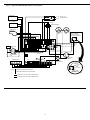
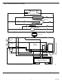
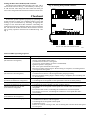
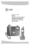
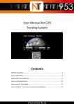
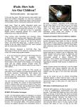
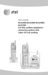
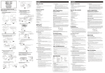
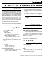
ST9141A1002 Electronic Fan Timer
Application
The ST9141A1002 Electronic Fan Timer integrates control of all combustion blower and circulating fan operations
in a gas warm air appliance. This control is the central
wiring point for most of the electrical components in the
furnace. The basic purposes of the ST9141A1002 are to
monitor the thermostat for heat, cool, and fan demands and
run the induced draft blower motor and up to a two-speed
circulating fan as required. The ST9141A1002 monitors an
spdt pressure switch, burner limit and primary limit. A
Honeywell SV9500 Hot Surface Pilot Ignition System
Control manages the burner, which is energized through
the pressure switch. A light-emitting diode (LED) indicates
system status.
In addition, this model includes electronic air cleaner
and humidifier convenience terminal connections.
LIGHT-EMITTING DIODE (LED) INDICATIONS:
LED flashing dim-bright indicates normal operation.
LED off when control is powered indicates defective
control.
LED on continuously when control is powered indicates
defective control.
LED flashing in a cycle with LED on followed by one
or more off pulses indicates the following system
errors.
Number
of Off
Flash
Pulses
1
2
3
NOTE: Use this control to replace an identical ST9141A1002
Electronic Fan Timer only. This control is not for use in
general applications.
4
System Condition
Burner limit circuit is open.
Primary limit circuit is open.
Pressure switch circuit is improperly closed.
Control is in lockout due to air
not circulating (overheating).
Specifications
ELECTRICAL RATINGS:
Power Requirements:
Voltage: 18-30 Vac, 60 Hz.
Contact Ratings:
Combustion Blower:
1.5A Full Load, 10A Locked Rotor at 115 Vac.
.75A Full Load, 5A Locked Rotor at 230 Vac.
Reduce full load rating by humidifier load.
Circulating Fan (Heat-Cool Speed):
15A Full Load, 30A Locked Rotor at 115 Vac.
7.5A Full Load, 15A Locked Rotor at 230 Vac.
Reduce full load rating by electronic air cleaner
load.
Thermostat Load: 0.06A plus ignition system current
draw.
ON/OFF DELAY SETTINGS:
Heat Speed:
Delay On: 30 seconds, fixed.
Delay Off: 60, 100, 140 or 180 seconds, field
adjustable.
Cool Speed:
Delay On: 6 seconds, fixed.
Delay Off: 60 seconds, fixed.
Timing Tolerance: Larger of ±5% or ±2 seconds.
POSTPURGE TIMING: 5 seconds.
ENVIRONMENTAL RATINGS
Temperature: -40° to +175° F [-40° to +79° C].
Humidity: 5 to 95%, noncondensing.
Installation
WHEN INSTALLING THIS PRODUCT…
1. Read these instructions carefully. Failure to follow
them could damage the product or cause a hazardous condition.
2. Check the ratings and specifications given in the
instructions and on the product to ensure the product is
suitable for your application.
3. Installer must be a trained, experienced service
technician.
4. After installation is complete, check out the product
operation as provided in these instructions.
!
CAUTION
Disconnect power supply before wiring to prevent electrical shock or equipment damage.
Location and Mounting
The ST9141A1002 is mounted in the appliance wiring
compartment using four No. 6 screws (obtained locally)
through holes on the corners of the enclosure.
Wiring
All wiring must comply with local codes and ordinances. Disconnect power before making wiring connections. Refer to Fig. 1 for standard wiring connections. Refer
to Fig. 2 for an internal schematic.
C.H. 1• 6-93 • ©Honeywell Inc. 1993 • Form Number 69-0780
69-0780
Fig. 1—Typical ST9141A1002 wiring connections.
HUMIDIFIER
L1 (H)
FUSE
L2 (N)
AIR CLEANER
TO 120 VAC
POWER SUPPLY
120 VAC
TRANSFORMER
24 VAC
COMBUSTION
BLOWER
2
3
C
NEUTRAL
N
CIR
STARTING
CAP
SV9500
HOT SURFACE
PILOT IGNITION
SYSTEM CONTROL
SEC
X
X
BLWR
HEAT
N
BURNER
LIMIT
4
XFMR
1
N
CONT
COOL
EAC
LEADS
DI
HUM
2
MOTOR
3
1
UNUSED
PRIMARY
LIMIT
LO
ML
MH
HI
N.C.
Z1
N.O.
ST9141
CIRCULATING
FAN
Z2
PRESSURE
SWITCH
THERMOSTAT
DELAY
1
W
Y
G
R
2
OFF
COOLING
CONTACTOR
SPEED
UP
C
Y
C
G
Y
W
R
24 VOLT
COMMON
24 VOLT
HOT
EFT
OUTPUT
NOTE:
24 VOLT
THERMOSTAT
OR PRESSURE
SWITCH
= DENOTES STANDARD TERMINAL.
= DENOTES TERMINAL NOT PROVIDED.
DENOTES LINE VOLTAGE CONNECTIONS.
DENOTES LOW VOLTAGE CONNECTIONS.
2
M5607
Fig. 2—ST9141A1002 internal schematic.
L1
(H)
FUSE
L2
(N)
TO 120 VAC
POWER SUPPLY
INTERLOCK
L1-1
N1
EAC (N)
EAC (S)
ELECTRONIC AIR CLEANER
LOW
M2
CIRCULATING
FAN
MED-LOW
K1
K2
HEAT
K2
COOL
MED-HIGH
M1
N2
HIGH
HUM (S)
HUM (N)
HUMIDIFIER
K3A
COMBUSTION
AIR BLOWER
DI
N3
N4
L1-2
120 VAC
TRANSFORMER
CN1
X
1
C
24 VAC
X-OT
BURNER
LIMIT
6
PRIMARY
LIMIT
ST9141A
ELECTRONIC
FAN TIMER
8
THERMOSTAT
C
R-OT
G
PS1
Y
3
N.C.
N.O.
W
K3B
R
COM.
7
PS2
FT
PRESSURE
SWITCH
24V
C
4
2
COOLING
CONTACTOR
5
24V
NOTE: DOTTED LINES REPRESENT PRINTED CIRCUIT BOARD WIRING.
3
SV9500 HOT SURFACE PILOT
IGNITION SYSTEM CONTROL
GND
TSTAT
FT
M5608
69-0780
Setting the Heat Fan Off Delay DIP Switches
Set the heat fan off delay DIP switches to 60, 100, 140 or
180 seconds as shown in Fig. 3. The off delay is factory-set
at 140 seconds. This delay time starts when the main gas
valve is de-energized at the end of a thermostat call for heat.
Fig. 3—Setting delay off DIP switches.
EAC
4
C
NEUTRAL
N
N
CIR
Checkout
Assure the system operates properly by operating the
system through at least one complete heating cycle and
cooling cycle. Troubleshoot by checking for appropriate
voltages at the ST9141A1002 terminals controlling the
combustion air blower and heat and cool speed circulating
fan. The ST9141A1002 schematic shows internal switching to clarify operation and assist in troubleshooting. See
Fig. 2.
3
SEC
XFMR
LEADS
2
X
X
BLWR
HEAT
HUM
2
1
N
CONT
COOL
1
DI
MOTOR
3
UNUSED
ST9141
Z1
Z2
DELAY
1
2
OFF
SPEED
UP
C
Y
G
C
Y
W
R
ON
OFF
1
2
1
2
1
2
60 SECONDS 100 SECONDS 140 SECONDS
1
2
180 SECONDS
DELAY OFF DIP SWITCH SETTINGS
M5658
ST9141A1002 Operating Sequence
Action
Thermostat calls for heat.
(W terminal is energized.)
System Response
• Pressure switch confirmed in no airflow position. (If pressure switch shows
airflow, LED flashes three times.)
• Combustion air blower is energized.
• Air proving switch makes (air flow is established).
• Ignition system is energized.
• Gas valve opens and main burner lights.
• Heat fan on delay timing begins. When timing is complete, circulating blower
is energized at heat speed.
Thermostat ends call for heat.
• Ignition system is de-energized and gas valve closes.
(W terminal is de-energized.)
• Combustion air blower is de-energized after postpurge timing.
• Heat fan off delay timing begins. When timing is complete, the circulating fan
is de-energized.
Thermostat begins call for cool.
• Cooling contactor is energized.
(G and Y terminals are energized.)
• Circulating fan is energized at cool speed after cool fan on delay timing.
Thermostat ends call for cool.
• Cooling contactor is de-energized.
(G and Y terminals are de-energized.) • Circulating fan turns off after cool fan off delay timing.
Thermostat begins call for fan.
• Circulating fan is energized at heat speed two seconds after G terminal is
(G terminal is energized.)
energized.
• If a call for heat occurs, circulating fan continues to run at heat speed.
• If a call for cool occurs, circulating fan switches to cool speed after foursecond delay.
Thermostat ends call for fan.
• Circulating fan is de-energized.
(G terminal is de-energized.)
Primary limit switch string opens.
• Thermostat and ignition system are de-energized and gas valve closes.
• Combustion air blower is de-energized.
• Circulating fan is energized at heat speed.
• LED flashes twice.
• If there is a call for cooling or fan, the circulating fan switches from heat speed
to cool speed.
(continued)
4
ST9141A1002 Operating Sequence (Continued)
Action
Primary limit switch string closes.
Primary limit switch string is open
for more than 150 seconds (on each
of three consecutive cycles).
Burner limit opens.
Burner limit closes.
Electronic air cleaner is connected.
(Connector to 120 Vac electronic
air cleaner.)
Humidity control is connected.
(Connector to 120 Vac humidifier.)
System Response
• Circulating fan turns off after the selected heat fan off delay timing.
• LED stops flashing.
• Normal operation resumes.
• Combustion air blower, circulating fan and ignition system are de-energized.
• Control goes into lockout mode.
• LED flashes four times.
• Control remains in lockout until 24V power is removed and reapplied (control
is reset).
• LED stops flashing.
• Normal operation resumes.
• Thermostat and ignition system are de-energized and gas valve closes.
• Combustion air blower and circulating fan heat speed are energized.
• LED flashes once.
• Combustion air blower remains energized for postpurge timing.
• The circulating fan remains energized for the selected delay off timing.
• LED stops flashing.
• Normal operation resumes.
• Electronic air cleaner is energized when the circulating fan heat or cool speed
is energized.
• Humidifier is energized when combustion air blower is energized.
5
69-0780
Home and Building Control
Honeywell Inc.
1985 Douglas Drive North
Golden Valley, MN 55422
Printed in U.S.A.
Home and Building Control
Honeywell Limited—Honeywell Limitée
740 Ellesmere Road
Scarborough, Ontario
M1P 2V9
6
Helping You Control Your World
QUALITY IS KEY