1
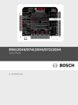
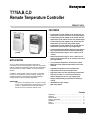
T775A,B,C,D
Remote Temperature Controller
PRODUCT DATA
FEATURES
• T775A models provide staged on-off control with one
temperature input and one to four relay output stages.
• T775B models provide staged on-off control with two
temperature inputs and two to four relay output stages.
• T775C models provide staged on-off control with one
temperature input and four relay output stages.
• T775D models provide staged on-off control with two
temperature inputs and four relay output stages.
• T775C,D models meet National Electrical Code (Article
547) requirements for animal confinement buildings.
T775A,B
T775A,B
APPLICATION
The T775 family of Electronic Remote Temperature
Controllers provide on-off temperature control for ducts, tanks,
chillers, heating and refrigeration units, and other applications
where electronic accuracy in addition to remote sensing is
desired.
In addition, certain models of the T775 family of controllers
provide on-off temperature control of heating, cooling, and
ventilating systems in agricultural confinement buildings,
storage areas and heavy industrial applications.
IMPORTANT
The T775 is an operating control, not a limit or safety
control. If used in applications requiring safety or limit
controls, a separate safety or limit control device
should be used in conjunction with the T775.
• Setpoint temperature range is -40° to +220°F (-40° to
+104°C).
• Ambient temperature range is -30° to +140°F for one
and two stage models and -30° to +125°F for three and
four stage models.
• Linear platinum temperature sensor with T775A,B.
• Water-tight linear platinum temperature sensor with
T775C,D.
• Adjustable temperature range and differential.
• LCD indication for mode and output status.
• Keypad provides ease of programming and operation.
• Accuracy is within +/- 1°F (at nominal operating
ambient temperature of 77°F and voltage input).
• Stage(s) independently programmed for heating or
cooling.
• 24/120/240 Vac input voltage.
• Spdt relay outputs.
Contents
Application ........................................................................ 1
Features ........................................................................... 1
Specifications ................................................................... 2
Ordering Information ........................................................ 2
Installation ........................................................................ 5
Wiring ............................................................................... 6
Checkout .......................................................................... 10
63-2489—2
T775A,B,C,D REMOTE TEMPERATURE CONTROLLER
SPECIFICATIONS
IMPORTANT
Specifications given in this publication do not include
normal manufacturing tolerances. Therefore, an
individual unit may not exactly match the listed
specifications. Also, this product is tested and
calibrated under closely controlled conditions
and some minor difference in performance can
be expected if those conditions are changed.
Models (see Table 1):
The T775A,B Electronic Temperature Controllers provide
staged on-off temperature control for ducts, tanks, chillers,
heating and refrigeration units, and other applications
where electronic accuracy and remote sensing are desired.
The T775C,D Electronic Remote Temperature Controllers
provide staged on-off temperature control of heating,
cooling and ventilating systems in agricultural confinement
buildings, storage areas, and heavy industrial applications.
Dimensions: See Fig. 1 and 2.
Mounting: Mounts on any suitable horizontal or vertical
surface (see Fig. 3 and 4 for mounting hole locations).
Temperature Accuracy: +/-1°F (at nominal voltage in 77°F
[25°C] ambient, nominal sensor value). Accuracy may vary
based on deviation from nominal values of input voltage,
operating ambient and sensor ambient.
Setpoint Adjustment Range: -40° to 220°F (-40° to 104°C).
Display Resolution: Sensed temperature and other
operating parameters are displayed via a liquid crystal
display (LCD) with a resolution of 1°F or 1°C.
Operating Ambient Temperature:
One and Two Stage units: -30° to 140°F.
Three and Four Stage units: -30° to 125°F.
Operating Humidity:
5% to 95% relative humidity (rh) noncondensing.
Sensor: Positive coefficient platinum type, 4.8 ohms/ °F,
1000 ft maximum distance between sensor and solid
state controller (requires calibration over 400 ft). To
maintain NEMA 4X rating, use environmental-proof
cable and sensor.
Electrical Ratings:
Voltage Input: 24/120/240 Vac, 50/60 Hz (+10%/-15%).
Power Consumption:
For one and two stage units:
8 VA maximum at 60 Hz.
10 VA maximum at 50 Hz.
For three and four stage units:
13 VA maximum at 60 Hz.
20 VA maximum at 50 Hz.
Table 1. T775 Models.
Model
Relay
Inputs Outputs
Maximum Operating
Ambient Temperature
Comments
T775A1001 1
1
140°F (60°C)
Includes one 193987GA Sensor.
T775A1019 1
2
140°F (60°C)
T775A1027 1
3
125°F (52°C)
T775A1035 1
4
125°F (52°C)
T775B1000 2
2
140°F (60°C)
T775B1018 2
3
125°F (52°C)
T775B1026 2
4
125°F (52°C)
T775C
1
4
125°F (52°C)
NEMA 4X enclosure. Includes one 203401B Remote Sensor.
T775D
2
4
125°F (52°C)
NEMA 4X enclosure. Includes two 203401B Remote Sensors.
Includes two 193987GA Sensors.
ORDERING INFORMATION
When purchasing replacement and modernization products from your TRADELINE® wholesaler or distributor, refer to the
TRADELINE® Catalog or price sheets for complete ordering number.
If you have additional questions, need further information, or would like to comment on our products or services, please write or
phone:
1. Your local Honeywell Automation and Control Products Sales Office (check white pages of your phone directory).
2. Honeywell Customer Care
1885 Douglas Drive North
Minneapolis, Minnesota 55422-4386
In Canada—Honeywell Limited/Honeywell Limitée, 35 Dynamic Drive, Scarborough, Ontario M1V 4Z9.
International Sales and Service Offices in all principal cities of the world. Manufacturing in Australia, Canada, Finland, France,
Germany, Japan, Mexico, Netherlands, Spain, Taiwan, United Kingdom, U.S.A.
63-2489—2
2
T775A,B,C,D REMOTE TEMPERATURE CONTROLLER
Contact Ratings:
1/2 hp; 9.8 FLA, 58.8 LRA at 120 Vac.
1/2 hp; 4.9 FLA, 29.4 LRA at 240 Vac.
125 VA pilot duty at 120/240 Vac.
10A at 24 Vac (resistive).
SELECT
SET
ENTER
Approvals:
Underwriters Laboratories Inc. Listed: File no. E4436.
Canadian Standards Assoc. certified: File no. LR47125.
8-1/2
(216)
Accessories:
T775A,B:
A775A1003 Temperature Sensor Simulator.
C7100C Duct Mount Averaging Sensor.
198212CA Water Resistant Sensor.
203401B Water Tight Sensor.
T7047C1090 Wall Mounted Sensor Case.
107324A Bulb Holder, duct insertion.
121371A Copper Immersion Well.
121371E Stainless Steel Well.
107048 Heat Conduction Compound, 4 ounce.
C7043A1098 Case and Immersion Well for running conduit
to sensor.
T775C,D:
121371A Copper Immersion Well.
121371E Stainless Steel Well.
107408 Heat Conduction Compound, 4 ounce.
C7043A1098 Case and Immersion Well for running conduit
to sensor.
5-7/32
(134)
1-1/4
(32)
1-1/4
(32)
3-13/16 (97)
4-3/4 (121)
2-3/8 (60)
M344C
7/8 (22) DIAMETER
Fig. 1. Approximate dimensions of T775A,B in in. (mm).
6 (153)
5-1/4 (133)
3-1/2 (89)
MOUNTING
HOLES
9
(229)
6-1/2
(165)
7/8 (22)
DIAMETER
1-1/4
(32)
1-3/8
(34)
M1301B
Fig. 2. Approximate dimensions of T775C,D in in. (mm)
3
63-2489—2
T775A,B,C,D REMOTE TEMPERATURE CONTROLLER
LCD TEMPERATURE
DISPLAY
C\F
F/C SELECTION
1 23 4
PROGRAMMING
KEYS
SET
SELECT
ENTER
SA SB
DIP SWITCHES FOR
SENSOR SELECTION.
PRESENT ON T775B
ONLY
MOUNTING HOLE
LOCATION
SENSOR INPUT,
TOD, AND 24VAC
TERMINALS
1
HOLE A
2
4
3
6
5
7
8
24V SENSOR
B
TOD
SENSOR
A
OUTPUT 2
KNOCKOUT B
LINE VOLTAGE
INPUTS
OUTPUT 1
NC
COM
NO
NC
COM
NO
120V
COM
240V
KNOCKOUT C
NO
COM
NC
NO
COM
NC
OUTPUT 3
OUTPUT 4
RELAY OUTPUT STAGES
(MAXIMUM OF FOUR STAGES)
NOTE: T775A TERMINAL BLOCK CONTAINS ONLY
TERMINALS 1-6 AND HAS NO DIP SWITCHES
M7423
FOR SENSOR SELECTION
Fig. 3. Feature locations for T775A,B.
LCD TEMPERATURE
DISPLAY
C\F
1 23 4
PROGRAMMING
KEYS
SET
SELECT
ENTER
1
HOLE A
2
3
4
SENSOR TOD
A
5
6
OUTPUT 2
HOLE B
7
8
24V SENSOR
B
MOUNTING
HOLES
OUTPUT 1
NC
COM
NO
NC
COM
NO
120V
COM
240V
NO
COM
NC
NO
COM
NC
OUTPUT 3
OUTPUT 4
LINE VOLTAGE
INPUTS
HOLE C
NOTE: T775C TERMINAL BLOCK CONTAINS ONLY
TERMINALS 1-6 AND HAS NO DIP SWITCHES
M7427
FOR SENSOR SELECTION
RELAY OUTPUT STAGES
Fig. 4. Feature locations for T775C,D.
63-2489—2
DIP SWITCHES FOR
SENSOR SELECTION.
PRESENT ON T775D
ONLY
SA SB
SENSOR INPUT,
TOD, AND 24VAC
TERMINALS
EARTH
GROUND
WIRE
F/C SELECTION
4
T775A,B,C,D REMOTE TEMPERATURE CONTROLLER
INSTALLATION
When Installing this Product...
1.
3.
4.
T775
C\F
1 23 4
2.
Read these instructions carefully. Failure to follow them
could damage the product or cause a hazardous
condition.
Check ratings given in instructions and on the product to
ensure the product is suitable for your application.
Installer must be a trained, experienced service
technician.
After installation is complete, check out product
operation as provided in these instructions.
SHIELDED
CABLE
CAUTION
Electrical Shock or Equipment Damage Hazard.
Can shock individuals or short equipment
circuitry.
Disconnect power supply before installation.
SET
SELECT
GROUND
SHIELD
TO T775
CABLE OR TO
GROUNDING
SCREW
ENTER
SA SB
1
2
SENSOR
A
3
4
TOD
5
6
7
8
24V SENSOR
B
OUTPUT 2
OUTPUT 1
NC
COM
NO
NC
COM
NO
Location and Mounting
Mount the controller on any convenient interior location using
the two mounting holes provided on the back of the metal
enclosure (mounting screws are not provided and must be
obtained separately). Use controller dimensions in Fig. 1
(T775A,B) or Fig. 2 (T775C,D) as a guide.
OUTPUT 3
NOTE: DO NOT GROUND
SHIELDED CABLE AT
SENSOR END.
Sensor Location
The 193987GA Sensor can be located up to 1000 feet (304m)
from the T775 using standard AWG 18/2 unshielded wire. For
cable runs greater than 25 feet shielded cable is
recommended. See Fig. 5. It may be located on pipes, in an
immersion well, in a wall-mounted case or on a bulb holder.
See Fig. 7. The 193987GA is not a water tight or water
resistant sensor. For wet applications, see the Accessories list
in the Specifications section.
Multiple sensors can be parallel-series wired to sense average
temperatures in large spaces.
To maintain control accuracy, the number of sensors parallelseries wired must be of the n2 power (for example, 4, 9, 16,
etc.). See Fig. 8.
Sensor Mounting
Sensors can be mounted on a wall or panel for sensing space
temperature (Fig. 7), strapped to a pipe or inserted in a well
(Fig. 6) for hot/cold water sensing, or taped to a standard cap
or bulb holder for duct air sensing. To prevent moisture or
condensation entering the sensor through the leadwire holes,
mount the sensor with the lead wires exiting the bottom of the
sensor.
NO
COM
NC
NO
COM
NC
SHIELDED
CABLE
120V
COM
240V
OUTPUT 4
GROUNDING SCREW
SENSOR
NOTE: TO MINIMIZE NOISE PICKUP, MAKE CONNECTION
FROM SHIELDED CABLE AS CLOSE AS POSSIBLE
TO SENSOR BODY.
M7430
Fig. 5. Using shielded cable (cable runs longer than 25 ft).
NOTE: Use heat conductive compound in immersion wells.
See Accessories in the Specifications section.
CAUTION
Electrical Shock Hazard.
Can short equipment circuitry.
Make sure that metal tube of sensor does not short
against T terminals in wall-mounted case.
COVER SENSOR
LEADS WITH
HEAT CONDUCTIVE
COMPOUND
SENSOR PLACED
IN WELL
1/2 NPT
IMMERSION
WELL
M5249
Fig. 6. Sensor inserted in immersion well.
5
63-2489—2
T775A,B,C,D REMOTE TEMPERATURE CONTROLLER
T7047C1090
WALLMOUNT SENSOR
CASE (OPTIONAL)
WIRING
193987GA
SENSOR
CAUTION
LEADWIRES
TO T775
Electrical Shock or Equipment Damage Hazard.
Can shock individuals or short equipment
circuitry.
Disconnect power supply before installation.
SCREW
TERMINAL
SCREW
TERMINAL
CAUTION
Do not use 24 Vac power at terminals 5 and 6 to
power any external loads if 120 Vac or 240 Vac is
used to power the T775.
IMPORTANT
The T775 is an operating control, not a limit or safety
control. If used in applications requiring safety or limit
controls, use a separate safety or limit control device
in conjunction with the T775.
Refer to Fig. 3 or 4 for locating the appropriate power inputs,
remote sensor input, load output terminals, contact closure
input and sensor selection switch. Access to the terminals can
be gained through standard conduit knockouts (A through C)
located around the perimeter of the enclosure.
CAUTION: POSITION SENSOR AWAY
FROM SCREW TERMINALS.
M8109C
Fig. 7. Sensor mounted on wall.
NOTE: Hole A should only be used for sensor, low-voltage
and contact closure wiring.
When wiring the input power, only one source of power can be
applied to the T775 (for example, 24 Vac or 120 Vac or
240 Vac). Knockouts B and C can be used to gain access to
120 Vac or 240 Vac input terminals and the load relay output
terminals.
SENSORS
See Fig. 11 through 14 for typical T775 wiring and applications.
TO T775 CONNECTIONS 1 AND 2 (SENSOR A)
OR 7 AND 8 (SENSOR B).
IMPORTANT
Poor wiring practices can cause erratic temperature
readings from the 193987GA Sensor. Avoid the
following to ensure proper operation:
• Do not route the temperature sensor wiring with
building power wiring.
• Do not locate the temperature sensor wiring next to
control contactors.
• Do not locate the temperature sensor wiring near
electrical motors.
• Do not locate the temperature sensor wiring near
welding equipment.
• Make sure good mechanical connections are made to
both the sensor and the controller.
• Do not mount the sensor with the leadwire end (wire
end) pointing up in an area where condensation can
occur.
M7431
Fig. 8. Parallel-series wiring of sensors.
If any of the above conditions cannot be avoided, use
shielded cable.
NOTE: Ground the cable shield at the T775 connection only,
not at the sensor connection (see Fig. 5).
63-2489—2
6
T775A,B,C,D REMOTE TEMPERATURE CONTROLLER
OPERATION
Control Algorithm
°F/°C Selection
On/Off Control
The T775AC operate with one temperature input supplied by
the remote sensor while T775B,D have two temperature
inputs. The T775A,B,C,D are all capable of providing up to four
stages of on/off control relay outputs. Each controller stage has
its own independent setpoint that can be configured to operate
in either the heating or cooling mode. The mode of operation
for each stage is user-determined by programming keys.
Heating Mode Operation
• Relay outputs energize at the temperature setpoint minus
the differential value.
• Relay outputs de-energize at the temperature setpoint
value.
Cooling Mode Operation
• Relay outputs energize at the temperature setpoint plus
differential value.
• Relay outputs de-energize at the temperature setpoint
value.
A single jumper plug controls °F/°C indication of the displayed
temperature value. See Fig. 3 and 4 for the location of this
jumper. The unit ships with the jumper installed in the °F mode.
To operate the device in the °C mode, remove the jumper.
Replacing the jumper reinstates the °F mode.
NOTES: If, upon removing the jumper plug, the device does
not display °C:
—
Remove power from the device.
—
Replace power to the device.
DIP Switch Selections
On the T775B,D, DIP switches are provided for assignment of
each relay output stage to its operating sensor. If an individual
switch is depressed to the right—toward its corresponding load
number (1 through 4 on DIP switch)—Sensor B is the
controlling sensor for that output stage. If an individual switch
is depressed to the left, Sensor A is the controlling sensor for
the output stage. An example of the switches and their
corresponding positioning is shown in Fig. 9.
EXAMPLE
Using a device with one input and one relay output, the
corresponding load energizes at the following temperatures
based on the initial settings:
• Setpoint: 68°F
• Differential: 2°F
SENSOR A
SWITCH
SENSOR B
LOAD 1
PWB
LOAD 2
SWITCH
LOAD 1 IS CONTROLLED BY
SENSOR A WHEN SWITCH IS
DEPRESSED ON THE LEFT
Outputs Energized
Heating Mode: Stage One energizes at 66°F.
PWB
Cooling Mode: Stage One energizes at 70°F.
A B
SIDE VIEW
The T775B,D have dual sensor inputs and allow two separate
controllers to exist within one enclosure. Selection of the stage
parameters (operation mode, setpoints, and differentials) is the
same as for a single sensor device after each stage is
assigned its operating sensor. This assignment is hardware
driven via a four position DIP switch. An explanation of the DIP
switch assignments appears in Fig. 9. See Fig. 3 and 4 for the
DIP switch location.
Fig. 9. DIP switch settings for sensor selection.
Device Setup
1.
Contact Closure Override Input
The two-terminal input allows the user to override a relayenergized condition on all outputs. This is done using contact
closure between terminal pins 3 and 4 (TOD). (See Fig. 3 and
4 for location.) This can be achieved manually or by using an
EMS controller or time clock with normally open contacts
(W7505 or S7005, for example).
When this override is active:
— The display shows the number of stages that would be
energized
— The words STAGE ENERGIZED flash on the display.
— Energized stages de-energize until the override returns to
inactive (Off).
LOAD 2 IS CONTROLLED BY
SENSOR B WHEN SWITCH IS
DEPRESSED ON THE RIGHT
(AS SHOWN)
M3292
Determine loads to be controlled and the operating mode
(heat or cool) and enter them in the Device Programming
Worksheet (Table 2).
Table 2. Device Programming Worksheet.
Load 1:
SetPt 1
On at
Diff 1
Off at
Load 2:
SetPt 2
On at
Diff 2
Off at
Load 3:
SetPt 3
On at
Diff 3
Off at
Load 4:
7
SetPt 4
On at
Diff 4
Off at
63-2489—2
T775A,B,C,D REMOTE TEMPERATURE CONTROLLER
Programming Keys
For example: Load 1: Compressor 1 (cool)
Setpt 1
On at
Diff 1
Off at
2.
For two sensor models (T775B), determine which loads
will be controlled from sensor A or sensor B and enter on
the worksheet.
For example: Load 1: Compressor 1 (cool)—Sensor A
Setpt 1
On at
Diff 1
Off at
3.
Determine setpoint (Setpt) and switching differential
(Diff) for each load and enter on the worksheet.
For example: Load 1: Compressor 1 (cool)—Sensor A
Setpt 1
78°F
On at
Diff 1
4°F
Off at
4.
Refer to the Control Algorithm subsection of Operation
section to calculate the load on and off temperatures.
Enter them on the worksheet.
NOTE: Remember that the on/off outputs are off at
setpoint in both heating and cooling operating
modes. When in cooling mode, the load turns
off at setpoint plus the differential. When in
heating mode, the load turns on at setpoint
minus the differential.
For example: Load 1: Compressor 1 (cool)—Sensor A
Setpt 1
78°F
On at
82°F
Diff 1
4°F
Off at
78°F
The T775 will not allow the user to program for both
heating and cooling loads to be energized at the
same time.
If this situation results, cooling loads will be energized
and heating loads will be prevented from energizing.
The number (1,2,3,4) of these nonenergized loads will
flash along with the word HEAT to indicate a call for
both heating and cooling loads controlled by one
sensor has occurred and to alert the user to reprogram
the affected control values.
Remove the T775 cover and enter the values listed on
the worksheet and the date in the first column on the
label inside the T775 cover.
Keypad Programming and Display
The T775 utilizes a Liquid Crystal Display (LCD) for interactive
prompting during programming and display of sensed and
assigned setpoint and differential values. User programming of
the T775 is accomplished through the four programming keys.
63-2489—2
IMPORTANT
Control values/operations are not placed in the microprocessor memory until the Enter key is pressed.
Press the Select and Enter keys at the same time to change
the control algorithm from heating to cooling or from cooling to
heating:
— Heating and cooling parameters are not displayed during
normal Select key sequences.
— The only parameters displayed after pressing the Select
and Enter keys at the same time are the stage indication,
and the word heat or cool.
— To change the operation from heating to cooling (or vice
versa) for a desired output stage, use the arrow keys.
— The next stage of heat or cool assignment appears after
pressing the Select key. When all stages are programmed,
the display reverts to sensed temperature and load
energized status.
NOTE: Control values and operation selection remain in the
device memory even after the power is removed.
Display
CAUTION
5.
The four programming keys are Select, Up and Down (arrows),
and Enter:
• Select: Sequentially prompts the user about what parameter
is being displayed. After the last parameter value is viewed,
pressing the Select key again displays the control values
from the beginning of the display loop. The parameters are:
— setpoint,
— differential,
— stage energized,
— heat or cool (operation mode),
— 1,2,3,4 (indicating assigned stage).
• Up and Down: Allow the displayed parameter to be
increased or decreased. After pressing Select, a control
value can be changed using these keys. Control values
increase or decrease by 1°F or 1°C each time an arrow key
is pressed.
• Enter: Places the new value in the microprocessor memory.
8
Once power is applied or restored to the device, the display
counts down from 210 until the display reads zero. During this
time all previously energized outputs de-energize. This is
intended to protect compressors in the event of a power failure.
NOTE: To avoid viewing the entire countdown, press the
Select key.
The LCD display now shows what it normally reads:
— load (sensed) temperature,
— stages energized,
— and, for two sensor devices, the sensor (Sensor A or
Sensor B) being read.
NOTE: At any time during programming, a 60 second pause
between key presses reverts the display to indicate
the sensed temperature and stage status.
For two sensor applications, the user has three options for
display of sensed temperature. The display can be configured
to:
— lock onto continuous Sensor A,
— lock onto continuous Sensor B sensed temperature,
— alternate between Sensor A and Sensor B (at approximate
five-second intervals).
T775A,B,C,D REMOTE TEMPERATURE CONTROLLER
This selection is accomplished in the Select screen scrolling
loop:
1. To lock on to either sensor, use the Select key to scroll
through the loop to the temperature prompt of interest.
2. Stop at Sensor A or Sensor B sensed temperature point.
3. When the loop is stopped at any other prompt, the display alternates between Sensor A and Sensor B sensed
temperatures.
NOTE: Pressing the Select key at the end of the programming sequence configures the display for
alternating temperature display.
Default Values
When power is initially applied to the T775, the control points
will be at their default value set at the factory. See Table 3 for
default values.
Table 3. Default Programming Values.
Differential (°F)
Operating Mode
Stage 1 72
2
Heat
Stage 2 70
2
Heat
Stage 3 68
2
Heat
Stage 4 66
2
Heat
1.
2.
3.
NOTE: If, upon removing the jumper plug, the device
does not display °C:
(a)Remove power from the device.
(b)Replace power to the device.
4.
5.
6.
7.
1.
2.
3.
4.
6.
7.
8.
9.
10.
For the T775B and D, assign the loads to the appropriate
sensor by setting the DIP switch in the upper right corner
of the T775 (see DIP Switch Selection, Fig. 9).
Before programming the T775, verify that the °F/°C
selection jumper is properly installed. The T775 ships
from the factory with the jumper in the °F position. If °C is
desired, remove the jumper.
Apply power to the device. The device begins counting
down from 210. This countdown sequence lasts for
approximately 3-1/2 minutes.
Press Select to override the time delay.
Press Select and Enter keys simultaneously to begin
programming the load operating mode (Heat or Cool).
Press the Set (down arrow) to change to cooling. The
Set (up arrow) changes back to heating.
Press Enter to program mode displayed into memory.
9
Press Select to go to the next stage.
Repeat steps 6 through 9 for additional stages.
Press Select after setting the last stage to return to the
display of the sensed temperature.
Programming Stage Control Values
5.
Device Programming
Setpoint (°F)
8.
9.
10.
Press Select to display the current stage setpoint.
Press Set (up arrow) to increase or Set (down arrow) to
decrease to the desired setpoint.
Press Enter to place the displayed value into memory.
Press Select to display the current stage switching
differential.
Press Set (up arrow) to increase or Set (down arrow) to
decrease the switching differential.
Press Enter to place the displayed value into memory.
Repeat steps 1 through 6 to program an additional stage.
To return to stage 1 parameters:
a. T775A,C: Press Select two times.
b. T775B,D: Press Select four times
Scroll through the programming loop a second time to
confirm that the appropriate values were entered into
memory by pressing Select.
For the T775A,C, skip to step 12.
NOTE: The T775B and D have three display options for the
sensed temperature:
(1) Sensor A only.
(2) Sensor B only.
(3) Alternating between Sensor A and Sensor B (at
approximately five-second intervals).
11.
12.
To change the T775B,D display option:
a. Sensor A only: Press Select after viewing the final
stage switching differential.
b. Sensor B only: Press Select a second time.
c. Alternate between A and B: Press Select a third time.
Before replacing the cover on the T775, check to see
that the control values were recorded on the label on the
backside of the cover.
IMPORTANT
1. For the T775A and C only: After initial programming,
altering the setpoints for stage 1 up or down results in
a change in setpoints 2, 3, and 4 by the same number
of degrees and in the same direction.
2. The control rejects any change to the stage 1 setpoint
if it results in exceeding control limits (-40° to +220°F
[-40° to +104°C]) for subsequent stages. This allows
easy sequential output staging modifications while
keeping the margin intact between setpoints.
63-2489—2
T775A,B,C,D REMOTE TEMPERATURE CONTROLLER
CHECKOUT
Error Messages
There are seven error messages that can display in response
to T775 software or hardware problems. The error Codes that
can flash on the display are:
• SF: Sensor Failure
— A flashing SF indicates an out-of-range or defective
sensor. Make sure that the sensors are connected
properly. For T775A,C all loads de-energize when this
error message flashes.
— For the T775B,D the loads controlled by the out-ofrange sensor de-energize. The display flashes SF to
indicate which sensor is defective or in error. In the
event that only one sensor is defective, the remaining
sensor and its load(s) operate normally. Only the
load(s) controlled by the defective, out-of-range, or
unconnected sensor de-energize.
NOTE: Sensor values below -40°F or above 220°F are
out-of-range.
• EF: EEPROM Failure
— The values read back from the EEPROM are not the
same as written into the EEPROM. This error cannot
be field repaired. Replace the device. The EEPROM is
not intended to be field repaired.
• CF: Calibration Failure
— A calibration resistor reading was not within the range
of the Analog to Digital converter. This error cannot be
field repaired. Replace the device.
• OF: Stray Interrupt Failure
— An unused interrupt occurred. This error cannot be field
repaired. Replace the device.
• CE: Configuration Error
— The device hardware was configured to a nonexistent
device. This error cannot be field repaired. Replace the
device.
sensor wire lengths. This temperature offset should be added
to the desired temperature setpoint for these applications.
Refer to programming instructions in the Programming section
for entering temperature setpoints.
Table 4. Temperature Offset Based on Wire Length.
Sensor Wire Length
None required.
400 to 599 ft
1.0 degrees
600 to 799 ft
2.0 degrees
800 to 1000 ft
3.0 degrees
After the controller is installed and wired, apply power. Make
initial adjustments and desired settings:
1. As shown in Fig. 10, record the sensed temperatures for
both Sensor A and Sensor B as displayed on the device.
Use the Select key to advance through the programming
loop to determine and then write, on the Checkout Table
(Fig. 10), the loads controlled by each sensor.
2. Write the operating mode (heat or cool) for each stage in
the Checkout Table (Fig. 10).
3. Write the sensed temperature for each load on the
Sensed Temp line.
4. Write the differential for each load on the Differential line.
5. Write the setpoint for each stage (Off temperature). Calculate the “On Temperature” for each stage.
NOTE: “On temperature” is setpoint plus differential for
cooling, and it is setpoint minus differential for
heating.
6.
7.
• OE: ROM Error
— The internal Read Only Memory (ROM) of the microprocessor is defective. This error cannot be field
repaired. Replace the device.
• AE: RAM error
— The internal Random Access Memory (RAM) of the
microprocessor is defective. This error cannot be field
repaired. Replace the device.
63-2489—2
10
Plot the on and off (open/closed) values at which the
device will energize and de-energize each output load,
(Refer to the Device Programming Worksheet.)
Verify which loads are energized by using the Checkout
Table (Fig. 10). As shown in the example, the display
indicates, in the lower right corner, energized stages. If
no stages are energized, the words “stage energized”
will not appear.
NOTE: If the sensed temperature is between the On
and Off temperatures, the load may either be
energized or de-energized. Refer to the Control
Algorithm section (in Operation) for further
explanation.
8.
Setpoint Calibration
To maintain temperature accuracy, use 18 AWG two-conductor
sensor wires. If the length of the sensor wire exceeds 400 feet,
recalibration will be necessary to maintain accuracy. Table 4
shows the corresponding temperature offset to use for different
Calibration Offset
0 to 399 ft
9.
If an error message flashes, refer to the description of
these messages. If SF flashes:
a. Check sensor connections.
b. If properly connected and SF continues to flash,
check the sensor location to make sure it is located
in an ambient condition that is within the sensor
capability (-40° to +220°F).
If an error message other than SF flashes, the device
cannot be field repaired. Replace the device.
T775A,B,C,D REMOTE TEMPERATURE CONTROLLER
CHECKOUT EXAMPLE WITH SENSOR A = 68 AND SENSOR B = 73
HEAT OR COOL
MODE
LOAD 1
(HEAT)
LOAD 2
(HEAT)
DIFFERENTIAL
2
2
DESIGNATED
SENSOR
A
B
SETPOINT
SENSED
TEMPERATURE
1
70
CLOSED
68
OPEN
LOAD 3
(HEAT)
LOAD 4
(HEAT)
2
2
A
B
1
72
OFF
70
ON
2
2
1
74
OFF
72
ON
2
1
76
OFF
74
ON
68
73
68
73
LOAD 1
IS ON
LOAD 2
IS OFF
LOAD 3
IS ON
LOAD 4
IS ON
2
STAGE ENERGIZED 1 3 4
SELECT
SET
ENTER
NOTE: RELAYS ARE DE-ENERGIZED AT SET POINT
CHECKOUT TABLE
HEAT OR COOL
MODE
LOAD 1
LOAD 2
LOAD 3
LOAD 4
DIFFERENTIAL
DESIGNATED
SENSOR
SETPOINT
SENSED
TEMPERATURE
1 INDICATES LOAD STATUS WHEN SENSED TEMPERATURE REACHES SETPOINT.
2 INDICATES LOAD STATUS WHEN SENSED TEMPERATURE REACHES SETPOINT
MINUS DIFFERENTIAL (HEAT MODE).
M7426A
Fig. 10. Checkout Table and checkout example with Sensor A = 68°F and Sensor B = 73°F.
11
63-2489—2
T775A,B,C,D REMOTE TEMPERATURE CONTROLLER
COOL MODE
C\F
3
1 23 4
SET
SELECT
ENTER
SA SB
TEMPERATURE
FALL
RELAY 1 AND 2
ENERGIZED
DIFFERENTIAL
2
SETPOINT 2
RELAY 1 ENERGIZED
2
L1
(HOT)
1
SENSOR A
24 VAC
1
2
SENSOR
A
3
4
TOD
5
6
24V
7
DIFFERENTIAL
1
8
2
SETPOINT 1
L2
NULL
TEMPERATURE
RISE
HEAT MODE
TEMPERATURE
FALL
OUTPUT 2
LOAD 2
LOAD 1
NULL
NC
COM
NO
NC
COM
NO
SETPOINT 1
DIFFERENTIAL
1
OUTPUT 1
120V
COM
240V
RELAY 1 ENERGIZED
SETPOINT 2
DIFFERENTIAL
2
RELAY 1 AND 2
ENERGIZED
1
POWER SUPPLY. PROVIDE DISCONNECT MEANS AND OVERLOAD PROTECTION AS REQUIRED.
2
FOR T775B,D: CONNECT SENSOR B TO PINS 7 AND 8.
3
DIP SWITCHES FOR SENSOR SELECTION. PRESENT OF T775B,D ONLY.
Fig. 11. Two-stage control, 24 Vac input, 24 Vac load.
63-2489—2
12
TEMPERATURE
RISE
M7421A
T775A,B,C,D REMOTE TEMPERATURE CONTROLLER
120 VAC INPUT; 120 VAC LOADS
C\F
3
1 23 4
SET
SELECT
ENTER
SA SB
2
SENSOR A
1
2
SENSOR
A
3
4
5
6
7
24V
TOD
OUTPUT 2
8
2
OUTPUT 1
120V
NC
COM COM
240V
NO
NC
COM
NO
WHT
1
120 VAC
BLK
COOL MODE
LOAD
LOAD 11
TEMPERATURE
FALL
LOAD 2
RELAY 1 AND 2
ENERGIZED
DIFFERENTIAL 2
SETPOINT 2
240 VAC INPUT; 240 VAC LOADS
RELAY 1 ENERGIZED
C\F
3
DIFFERENTIAL 1
1 23 4
SET
SELECT
NULL
SETPOINT 1
ENTER
TEMPERATURE
FALL
SA SB
TEMPERATURE
RISE
HEAT MODE
NULL
SETPOINT 1
DIFFERENTIAL 1
2
SENSOR A
1
2
SENSOR
A
3
4
TOD
5
6
24V
7
8
RELAY 1 ENERGIZED
2
SETPOINT 2
DIFFERENTIAL 2
OUTPUT 2
RELAY 1 AND 2
ENERGIZED
OUTPUT 1
120V
NC
COM COM
240V
NO
NC
COM
NO
TEMPERATURE
RISE
RED
240 VAC 1
BLK
LOAD
LOAD 11
LOAD 2
1
POWER SUPPLY. PROVIDE DISCONNECT MEANS AND OVERLOAD PROTECTION AS REQUIRED.
2
FOR T775B,D: CONNECT SENSOR B TO PINS 7 AND 8.
3
DIP SWITCHES FOR SENSOR SELECTION. PRESENT OF T775B,D ONLY.
M7422A
Fig. 12. Two-stage control, 120 or 240 Vac input; 120 or 240 Vac load.
13
63-2489—2
T775A,B,C,D REMOTE TEMPERATURE CONTROLLER
120 VAC INPUT; 120 VAC LOADS
C\F
3
1 23 4
SET
SELECT
ENTER
SA SB
COOL MODE
1
2
SENSOR A
2
SENSOR
A
3
4
5
6
TEMPERATURE
FALL
8
7
24V SENSOR
B
TOD
2
RELAY 1,2,3 AND 4
ENERGIZED
DIFFERENTIAL 4
SETPOINT 4
OUTPUT 2
OUTPUT 1
NC 120V
COM COM
NO 240V
NC
COM
NO
DIFFERENTIAL 3
OUTPUT 3
SETPOINT 3
WHT
NO
COM
NC
NO
COM
NC
RELAY 1,2 AND 3
ENERGIZED
120 VAC
BLK
OUTPUT 4
1
RELAY 1 AND 2
ENERGIZED
DIFFERENTIAL 2
SETPOINT 2
RELAY 1 ENERGIZED
DIFFERENTIAL 1
LOAD 4
LOAD 3
LOAD 2
LOAD 1
TEMPERATURE
RISE
SETPOINT 1
NULL
240 VAC INPUT; 240 VAC LOADS
HEAT MODE
C\F
3
1 23 4
TEMPERATURE
FALL
SET
SELECT
NULL
SETPOINT 1
ENTER
DIFFERENTIAL 1
SA SB
RELAY 1 ENERGIZED
SETPOINT 2
1
2
SENSOR A
2
SENSOR
A
3
4
TOD
5
6
DIFFERENTIAL 2
8
7
RELAY 1 AND 2
ENERGIZED
24V SENSOR
B
2
SETPOINT 3
DIFFERENTIAL 3
OUTPUT 2
RELAY 1,2 AND 3
ENERGIZED
OUTPUT 1
NC 120V
COM COM
NO 240V
NC
COM
NO
NO
COM
NC
NO
COM
NC
OUTPUT 3
OUTPUT 4
SETPOINT 4
DIFFERENTIAL 4
RED
240 VAC 1
RELAY 1 ,2,3 AND 4
ENERGIZED
TEMPERATURE
RISE
BLK
T775A
LOAD 4
LOAD 3
LOAD 2
LOAD 1
1
POWER SUPPLY. PROVIDE DISCONNECT MEANS AND OVERLOAD PROTECTION AS REQUIRED.
2
FOR T775B,D: CONNECT SENSOR B TO PINS 7 AND 8.
3
DIP SWITCHES FOR SENSOR SELECTION. PRESENT OF T775B,D ONLY.
Fig. 13. Four stage control, 120 or 240 Vac input, 120 or 240 Vac load.
63-2489—2
14
M7424A
T775A,B,C,D REMOTE TEMPERATURE CONTROLLER
C\F
3
1 23 4
SET
SELECT
ENTER
SA SB
2
L1
(HOT)
1
1
SENSOR A
2
3
SENSOR
A
24 VAC
4
TOD
6
OUTPUT 2
2
OUTPUT 1
NC 120V
COM COM
NO 240V
NC
COM
NO
LOAD 1
LOAD 2
NO
COM
NC
NO
COM
NC
OUTPUT 3
COOL MODE
TEMPERATURE
FALL
OUTPUT 4
HEAT MODE
RELAY 1,2 AND 3
ENERGIZED
TEMPERATURE
FALL
DIFFERENTIAL 3
SETPOINT 3
8
7
24V SENSOR
B
L2
LOAD 3
LOAD 4
5
NULL
DIFFERENTIAL 1
RELAY 1 ENERGIZED
RELAY 1 AND 2
ENERGIZED
SETPOINT 2
DIFFERENTIAL 2
DIFFERENTIAL 2
SETPOINT 2
SETPOINT 1
RELAY 1 AND 2
ENERGIZED
RELAY 1 ENERGIZED
SETPOINT 3
DIFFERENTIAL 3
DIFFERENTIAL 1
SETPOINT 1
NULL
TEMPERATURE
RISE
RELAY 1,2 AND 3
ENERGIZED
TEMPERATURE
RISE
NOTE: FOR THERMOSTAT APPLICATIONS, CONNECT CONTACT NO OF COOLING STAGE TO Y1 (AND SECOND STAGE TO Y2)
CONNECT CONTACT NO OF HEATING STAGE TO W1 (AND SECOND STAGE TO W2).
1
POWER SUPPLY. PROVIDE DISCONNECT MEANS AND OVERLOAD PROTECTION AS REQUIRED.
2
FOR T775B,D: CONNECT SENSOR B TO PINS 7 AND 8.
3
DIP SWITCHES FOR SENSOR SELECTION. PRESENT OF T775B,D ONLY.
M7425A
Fig. 14. Four-stage control, 24 Vac input; 24 Vac load.
15
63-2489—2
Automation and Control Solutions
Honeywell International Inc.
Honeywell Limited-Honeywell Limitée
1985 Douglas Drive North
35 Dynamic Drive
Golden Valley, MN 55422
Scarborough, Ontario M1V 4Z9
customer.honeywell.com
® U.S. Registered Trademark
© 2005 Honeywell International Inc.
63-2489—2 B.B. Rev. 07-05