1
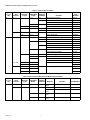
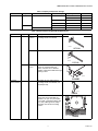
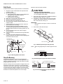
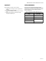
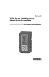
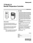
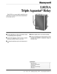
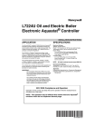
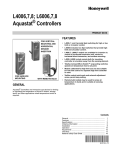
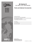
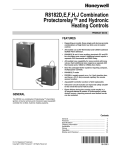
Immersion Wells and Compression Fittings
FOR TEMPERATURE CONTROLLERS
PRODUCT DATA
FEATURES
121371B
IMMERSION WELL
• Immersion wells and compression fittings are
available to fit a 1/2-14 or 3/4-14 NPT tapping with
a range of insulation depths.
• Immersion wells and compression fittings are
available in a variety of lengths and diameters.
112632AA
IMMERSION WELL
• Immersion wells and compression fittings are
available in a variety of materials, to suit the
application. Materials include: brass, copper,
stainless steel, mild steel or Monel.
• Element holders support the capillary and bulb
or an averaging element in duct applications.
107324A
ELEMENT
HOLDER
• Bulb shields protect the sensing bulb from sun
and weather with the bulb installed outdoors.
104484A
COMPRESSION FITTING
APPLICATION
Immersion wells, compression fittings and element holders
are used with Aquastat® Temperature Controllers to hold the
temperature sensing bulb in the controlled medium.
Immersion wells and compression fittings also prevent
leakage of the controlled medium.
• Accessories, including mounting clips, heatconductive compound, waste nuts, a pipe strap
and a well adapter, are available for mounting
sensing bulbs in various applications.
• Immersion wells allow heat transfer while
protecting the sensing bulb from contact with the
controlled medium.
• Immersion wells permit removal of the sensing
bulb for testing or replacement without draining
the system.
• Compression fittings seal the boiler and allow
bulb insertion directly into the controlled
medium.
Contents
Application ........................................................................ 1
Features ........................................................................... 1
Specifications ................................................................... 2
Ordering Information ........................................................ 2
General Information .......................................................... 7
Installation ........................................................................ 8
Checkout .......................................................................... 13
Cross Reference .............................................................. 13
68-0040-04
IMMERSION WELLS AND COMPRESSION FITTINGS
SPECIFICATIONS
Models:
Immersion Wells: Allow heat transfer while protecting sensing
bulb from controlled medium and seal off tapping to permit
bulb removal without draining the boiler. Available in
copper, stainless steel, mild steel and Monel. See Table 1
for copper. See Table 2 for stainless steel, mild steel and
Monel.
Compression Fittings: Allow bulb insertion directly into the
controlled medium with boiler draining. Can also be used to
provide positive seal in duct applications. Available in brass
and stainless steel. See Table 3.
Element Holders: Support bulb and capillary or averaging
element in a duct. See Table 4.
Dimensions:
See Tables 1, 2, 3 and 4, and Fig. 1 and 2.
Element Holders:
311266D Bulb Holder: -40°F to +100°F (-40°C to +38°C).
Other Element Holders: Maximum temperature rating limits
of the controller sensing bulb and capillary.
Maximum Pressure Ratings:
Copper Wells: 255 psi (1758 kPa) at 300°F (149°C).
Other Wells: 1500 psi (10,342 kPa) at 700°F (371°C).
Capillary Compression Fittings:
Water: 50 psi (345 kPa)
Air: 15 psi (103 kPa).
Accessories:
See Tables 5 and 6.
PACKING
NUT
Temperature Ratings:
INSULATION DEPTH
TUBING
IMPORTANT
Do not exceed the maximum temperature rating of
the controller element.
Wells:
Copper: 300°F (149°C) maximum.
Other Materials: Maximum temperature rating limits of the
controller sensing bulb and capillary.
Capillary Compression Fittings: 250°F (121°C) maximum.
SLOTTED
BRASS
WASHERS (4)
FITTING FOR 1/2
OR 3/4-14 NPT
TAPPED HOLE
MINIMUM
INSERTION LENGTH
APPROXIMATELY 4-3/4 IN.
COMPOSITION DISK
M17260
Fig. 1. Capillary compression fitting
dimensions and components.
ORDERING INFORMATION
When purchasing replacement and modernization products from your TRADELINE® wholesaler or distributor, refer to the
TRADELINE® Catalog or price sheets for complete ordering number.
If you have additional questions, need further information, or would like to comment on our products or services, please write or
phone:
1. Your local Honeywell Automation and Control Products Sales Office (check white pages of your phone directory).
2. Honeywell Customer Care
1885 Douglas Drive North
Minneapolis, Minnesota 55422-4386
In Canada—Honeywell Limited/Honeywell Limitée, 35 Dynamic Drive, Toronto, Ontario M1V 4Z9.
International Sales and Service Offices in all principal cities of the world. Manufacturing in Australia, Canada, Finland, France,
Germany, Japan, Mexico, Netherlands, Spain, Taiwan, United Kingdom, U.S.A.
68-0040—04
2
IMMERSION WELLS AND COMPRESSION FITTINGS
WELL SPUD. FITS 1/2 OR
3/4-14 NPT TAPPED HOLE
MOUNTING
CLAMP
MOUNTING
FLANGE
1/8-1/2 in. OF THREADS MAY
EXTEND INTO CONTROLLED MEDIUM
121371A-S
123869A-123872A
(LESS MOUNTING CLAMP)
WELL SHELL.
INSERTION/MAX
BULB LENGTH
INSULATION
DEPTH
NOTE: 123870F HAS DUAL
DIAMETER WELL SHELL.
122555A,B
FITS 1/2 OR 3/4-14 NPT TAPPED HOLE
MOUNTING
FLANGE
INSERTION/MAX
BULB LENGTH
INSULATION DEPTH
122555E
DUAL DIAMETER WELL
FITS 1/2 OR 3/4-14 NPT TAPPED HOLE
MOUNTING
FLANGE
INSERTION/MAX
BULB LENGTH
INSULATION DEPTH
123732AA
FITS 1/2 OR 3/4-14 NPT
TAPPED HOLE
SET SCREW
INSERTION/MAX
BULB LENGTH
INSULATION
DEPTH
FITS 1/2 OR 3/4-14 NPT TAPPED HOLE
MOUNTING
FLANGE
INSERTION/MAX BULB LENGTH
INSULATION DEPTH
FITS 1/2 OR 3/4-14 NPT
TAPPED HOLE
MOUNTING
FLANGE
SPRING
CLIP
138134E
DUAL DIAMETER WELL
INSERTION/MAX
BULB LENGTH
INSULATION DEPTH
FITS 1/2 OR
3/4-14 NPT
TAPPED HOLE
138134B
112620AA-112639AE
1/8-1/2 in. OF THREADS MAY
EXTEND INTO CONTROLLED MEDIUM
WELL SHELL
INSULATION
DEPTH
INSERTION/MAX
BULB LENGTH
M17259A
Fig. 2. Immersion well dimensions and components.
3
68-0040—04
IMMERSION WELLS AND COMPRESSION FITTINGS
Table 1. Copper Immersion Wells.
Spud in
in. x 14
NPT
1/2
Shell ID/
Bulb
Diameter
3/8
Insertion/
Max Bulb
Length
3
Insulation
Depth
1-1/2
3
1/2
3/4
3/8
3-1/2
1-1/2
3-3/4
1-1/2
4-1/4
1-1/2
4-1/4
4-1/2
3
1-1/2
3
Capillary
Diameter
121371 Mounting Clamp
121371A
—
—
123869A
Spud setscrew for armored capillary, plug
123732AA
121371 Mounting Clamp
121371L
5/64
121371 Mounting Clamp
121371P
1/8
112721 Spring Clip
112620AA
—
Plastic sleeve on well tube
123869B
1/8
112721 Spring Clip
112622AA
112721 Spring Clip
112626AA
5/64
121371 Mounting Clamp
121371B
—
—
123870A
5/64
121371 Mounting Clamp
121371M
121371 Mounting Clamp, plastic sleeve
123171N
—
123871A
Plastic sleeve on well tube
123871B
—
122555D
4-1/2
—
Plastic sleeve on well tube
122555A
1-1/2
5/64
121371 Mounting Clamp
121371Q
2-1/4
—
—
138134B
Plastic sleeve on well tube
122555B
—
122555C
Plastic sleeve on well tube
138134E
4-1/2
3/8 + 5/8
3
1/2
4-1/4
2-1/4
4-1/2
8-1/4
Part
Number
5/64
—
3-1/2
Includes
1-1/2
122555E
1/8
112721 Spring Clip
112630AA
4
112634AA
1-1/2
112630AB
Table 2. Stainless Steel, Mild Steel, and Monel Immersion Wells.
Spud in
in. x 14
NPT
1/2
68-0040—04
Shell ID/
Bulb
Diameter
Insertion/
Max Bulb
Length
Insulation
Depth
Capillary
Diameter
Material
Includes
Part Number
3/8
3
1-1/2
5/64
Stainless
steel
121371 Mounting Clamp
121371E
1/2
4-1/4
1
1/8
Mild steel
112721 Spring Clip
112623AA
Stainless
steel
112721 Spring Clip
112624AA
4
1/8
Stainless
steel
112721 Spring Clip
112628AA
1
1/8
Stainless
steel
112721 Spring Clip
112632AA
4
IMMERSION WELLS AND COMPRESSION FITTINGS
Table 3. Capillary Compression Fittings.
Material
Brass
Spud
1/2-14 NPT
Maximum Bulb Diameter
1/2 in.
Insulation Depth
1-5/16 in.
3/4-14 NPT
11/16 in.
Capillary Diameter
Part Number
5/64 in.
104484A
1/8 in.
7617M
1-1/2 in.
5/64 in.
104484C
2 in.
5/64 in.
7617ABY
1-5/8 in.
5/64 in.
104484B
1-1/2 in.
1/8 in.
7617P
Table 4. Element Holders for Duct-Mount Applications .
Application
Length
Plate Size
Description
Bulb holders
8-5/8 in.
2-3/4 in.
x 1-3/4 in.
Supports capillary and bulb in duct;
mounting screws not included.
Part Number
M17275A
107324A
2-3/4 in x 3 in.
M17276A
14 in.
3-1/4 in x
3-1/4 in.
Holds 1 or 2 elements in 0°F to
100°F air; grommet holds one
5/64 in. and one 1/8 in. diameter
capillary; helps reduce airflow through
opening in duct.
131524A
M17277A
311266D
Averaging
—
element holders
—
Mounting clip; use with grommet;
mounting screws not included; one
required per clip.
M17271
314439
Use with 1/2 in. EMT thinwall conduit
where duct access is limited. Kit
includes 4 in. (101 mm) cover plate,
1/2 in. EMT compression fitting, 3/16
in. (5 mm) rubber grommet, clamp
assembly, wire ties and mounting
screws.
7640HX
5
M17279
68-0040—04
IMMERSION WELLS AND COMPRESSION FITTINGS
Table 5. Immersion Well Accessories .
Description
Mounting clamp
Size in in.
(except where noted)
Application
Part Number
1/2 or 3/4 in. well spud; 5/64
capillary
Holds capillary in place on
123869A-123872A;
122554A,B; 12255A,B,D,E;
and 138134B-F Immersion
Wells.
M17274
121371AA
Spring clip
M17288
32002656-001
1/2 in well spud; 5/64 capillary
Holds capillary in place on
1122620AA-112639AB
Immersion Wells.
104488
1/2 in. well spud; 1/8 capillary. 112721
3/4 in. well spud; 1/8 capillary. 112720
M17280
Heat-conductive compound
Improves heat conduction in
well applications where bulb
does not fit tightly.
4 oz. (118 ml)
M17281
107408
Single application tube (1/2 oz)
M17282
120650
Well Adapter
Adapts well with setscrew on
spud; for use with direct
insertion bulb or 121371AA
Mounting Clamp.
M17283
124904
68-0040—04
6
IMMERSION WELLS AND COMPRESSION FITTINGS
Table 6. Accessories for Duct-Mount Applications
Description
Bulb shield assembly
Application
Size
Part Number
Shields bulb from weather; 6 in. (152 mm) long; holds 3/8
less mounting screws and in. and 1/2 bulbs.
split plug.
M17284
107323A
Shields bulb from weather; 7 in. (118 mm) long, clip holds
includes mounting screws 3/8 in. bulb.
and 33578 Split Plug.
M17285
34886A
Pipe Strap
Fastens bulb to outside of
pipe.
4-1/2 in. (114 mm) long; used
with up to 3/4 in. OD pipe.
M17286
105900
GENERAL INFORMATION
maximum temperature and pressure ratings or greater
corrosion resistance. Some copper wells are available with a
plastic sleeve over the tube to reduce electrolytic and corrosive
activity.
Immersion Wells
An immersion well consists of a metal tube, called the well
shell, closed on one end. A well spud externally threaded to fit
standard boiler tappings is welded or brazed on the open end.
See Fig. 1. The well is inserted into the tank and the
temperature sensing bulb is inserted into the well. The sensing
bulb never touches the controlled medium. Because the well
conducts heat rapidly, the bulb responds quickly and
accurately to temperature changes in the controlled medium.
An immersion well protects the temperature sensing bulb from
mechanical damage or damage due to chemical interaction
with the controlled medium. Also, a well permits removal of the
sensing bulb for testing or control replacement without draining
the system. The threaded fitting of the well spud provides a
tighter seal than a packing nut applied to the capillary.
Material Selection
The immersion well material must conduct heat readily and
resist corrosive and electrolytic action (especially in brine
solutions and when the well is a different material than the
container). The material must also resist fluid contamination
from chemical reaction with the well and withstand high
temperatures. Most Honeywell immersion wells are copper
because of its high conductivity. Stainless steel, mild steel and
Monel wells are also available for applications requiring higher
7
Well Sizing
Major factors in selecting well size are:
—size of the boiler tapping.
—bulb diameter.
—insulation depth.
—insertion length.
Immersion wells are available to fit standard 1/2-14 NPT and 3/
4-14 NPT tappings. Sensing bulbs are 3/8, 1/2 or 11/16 in. in
diameter with well shells designed to fit these diameters. The
bulb should fit tightly in the shell. If the bulb fits loosely, fill the
space between the shell and bulb with heat-conductive
compound to ensure maximum heat transfer. Many Honeywell
temperature controllers ship with heat-conductive compound;
available in 4-oz cans and 1/2-oz single-application tubes. See
Table 4.
he nominal length of the spud, including the full length of the
threads and the hex, defines the insulation depth. Depending
on the characteristics of the tapping, 1/8 to 1/2 in. of the
68-0040—04
IMMERSION WELLS AND COMPRESSION FITTINGS
threaded end of the spud can extend into the controlled
medium. Consider this additional length when determining how
far the well extends into the controlled medium.
The length of the well shell starting at the end of the spud
defines the insertion length. This is the active part of the well
where the fastest heat transfer occurs. The bulb should be the
same length as the well shell; however, the well shell can be
longer, but not shorter, than the length of the bulb. Longer
shells require inserting the bulb until the end touches the well
bottom. Shorter shells do not expose the full length of the bulb
to the temperature of the controlled medium, inhibiting proper
temperature controller operation.
Securing Bulb in Well
REMOTE BULB APPLICATIONS
Securing the capillary at the spud with a spring clip or a
mounting clamp holds the sensing bulb securely in place. See
Fig. 1. Use the spring-loaded clip on well spuds with no
mounting flange. Slip it over the capillary and snap it in place in
the end of the spud. The mounting requires sizing to fit both the
spud and the capillary diameter. The mounting clamp requires
wells with a mounting flange at the spud end. The jaws adjust
to fit both 1/2 and 3/4 in. spuds, and it holds a 5/64 in. capillary.
Wells are available with and without the matching spring clip or
mounting clamp. This mounting hardware is also available
separately.
A few wells have a setscrew in the spud. These wells are
designed for use on controllers with an armored capillary that
has a brass plug at the sensing bulb end; for example,
R8182H,J.
DIRECT INSERTION APPLICATIONS
Most Honeywell direct insertion controllers include provision for
clamping the controller case on the immersion well spud. This
requires a well spud with a mounting flange at the end. If the
well spud has a setscrew, but no mounting flange, a 124904
Well Adapter can provide the necessary flange. See Fig. 3.
The well adapter is shipped with several Honeywell
TRADELINE® direct-insertion controllers.
Capillary compression fittings are used to replace an
immersion well when the sensing bulb of a remote bulb
controller requires direct insertion into the controlled medium.
The fitting seals around the capillary. However, compression
fittings cannot seal off against as much pressure as immersion
wells. Capillary compression fittings can be used in duct
applications to minimize air leakage from the duct; a waste nut
is recommended to provide a secure mounting.
Material Selection
Capillary compression fittings are available in brass and
stainless steel. In hydronic applications, brass fittings with
copper sensing bulbs are used and stainless steel is used with
all other fittings to minimize electrolytic action.
Sizing
Capillary compression fittings must fit the tapping and the
capillary diameter. Because the spud must slip over the bulb
during installation, 11/16 in. bulbs require 3/4 in. spuds.
Element Holders
Bulb holders are used to support a remote bulb and capillary in
a duct, but are not suitable for hydronic applications. A bulb
holder must be selected according to the length needed to
support the bulb in the main airstream and the need for
plugging the opening in the duct wall.
For best response, string averaging elements evenly back and
forth across the duct. The element is held in place with either
perforated pipe strap or 314439 Mounting Clips. If access to
the duct is limited, use the 7640HX Duct Mounting Kit. Always
use a grommet to protect the element from abrasion where it
enters the duct.
NOTE: To minimize heat loss through the fitting, use a waste
nut and compression fitting.
INSTALLATION
When Installing this Product…
SETSCREW
BACK
OF
CASE
1.
BOILER
WALL
IMMERSION
WELL CLAMP
2.
WELL
SPUD
WELL
CLAMP
SCREW
WELL
ADAPTER
SENSING BULB
WELL
SHELL
3.
4.
M17261
Fig. 3. Mounting direct insertion controller
case on well spud.
WARNING
Capillary Compression Fittings
A capillary compression fitting includes a spud, several
aligning washers, a neoprene packing ring and a packing nut.
The spud is internally threaded to hold the packing material
and the packing nut and externally threaded to fit standard
boiler tappings. The washers and packing ring are sized to fit a
particular capillary diameter.
68-0040—04
Read these instructions carefully. Failure to follow them
could damage the product or cause a hazardous
condition.
Check the ratings given in the instructions and on the
product to make sure the product is suitable for your
application.
Installer must be a trained, experienced service technician.
After installation is complete, check out product operation as provided in these instructions.
8
Severe Scalding Hazard.
Contact with hot liquid can cause severe injury or
death.
Drain system before beginning well or compression
fitting installation.
IMMERSION WELLS AND COMPRESSION FITTINGS
WARNING
Electrical Shock Hazard or Equipment Damage
Hazard.
Can cause sever injury, death or short equipment
circuitry.
Disconnect all power supplies before installation.
Most equipment manufacturers provide a tapping for
temperature controller sensing element insertion. The tapping
should be located to measure average system temperature.
IMPORTANT
Always install the sensing element away from hot or
cold water inlets, steam coils, and locations where the
well pressure rating will be exceeded.
1.
2.
3.
Turn off the power.
If the system is filled, drain it to a point below the boiler
tapping or sensing element location.
If no tapping is provided, prepare one, properly threaded,
at the desired location.
1.
2.
3.
Fill the well with compound.
Coat the bulb generously before inserting it into the well.
Move the bulb up and down inside the well to ensure
even distribution of compound.
Securing Bulb with Mounting Clamp
Use the 121371 Mounting Clamp only on wells with a mounting
flange on the spud end.
1.
2.
3.
Loosen the draw nut and spread the jaws of the clamp
with a screwdriver. See Fig. 5.
Slide the clamp jaws over the spud mounting flange
(point A in Fig. 5).
Adjust the tubing to fit through the mounting clamp
groove (point B in Fig. 5).
IMPORTANT
When tightening the draw nut, be careful not to
damage the capillary.
4.
Immersion Well Mounting
Tighten the draw nut so that the retainer clamp attaches
firmly to the well spud and holds the tubing securely in
place.
Instructions for mounting the well in the tapping and using the
capillary mounting clamp or spring clip in remote bulb
applications follow. Consult the appropriate Aquastat®
Controller instructions for mounting the controller on the well in
direct insertion applications. Direct insertion applications
usually require using wells with a mounting flange on the spud.
1.
JAWS
SPREAD JAWS
TO FIT OVER
RIDGE ON
WELL SPUD
Coat threads with a moderate amount of pipe dope, leaving two end threads bare. See Fig. 4.
SCREWDRIVER
NOTE: Teflon™ tape can also be used.
2.
MOUNTING CLAMP
Screw the immersion well into the tapping and tighten
securely.
DRAW
NUT
MOUNTING
CLAMP
B
SPUD
WELL
BULB
APPLY A MODERATE AMOUNT
OF PIPE COMPOUND (LEAVE
TWO END THREADS BARE).
TUBING
M17262
M8777
A
Fig. 4. Proper application of pipe dope.
Fig. 5. Fastening bulb in well using mounting clamp.
Insert Sensing Bulb in Well
For good temperature response, the immersion well must fit
the sensing element or bulb tightly and rest against the bottom
of the well.
NOTE: If necessary, bend the tubing to hold the bulb against
the bottom of the well.
IMPORTANT
Any bends made in the piping must be gradual to prevent breaks in the tubing and subsequent loss of fill.
For faster heat transfer, use heat-conductive compound to fill
the space between the bulb and the well. A tube of
heat-conductive compound ships with Honeywell
TRADELINE® Aquastat Controllers. The compound is also
available as an accessory. See Table 5. Use the following
procedure when installing the compound:
9
Securing Bulb with Spring Clip
The spring clip can be used with any well with the appropriately
size spud. Wells without a mounting flange on the spud require
a spring clip.
NOTE: The spring clip does not hold the capillary as securely
as does the mounting clamp. See Table 5 for spring
clip part numbers.
1.
2.
Slide the clip over the capillary with the prongs facing the
well.
Push the clip as far as possible into the spud. See Fig. 6.
NOTE: Make sure the bulb remains bottomed in the well.
68-0040—04
IMMERSION WELLS AND COMPRESSION FITTINGS
Element Holders
FITTING (INCLUDING WELL)
TUBING
SPRING CLIP
Use element holders to mount air temperature sensors in a
duct. Locate the sensing element where air at representative
temperatures can circulate around it. In a plenum application,
locate the element far enough from the combustion chamber to
avoid the effect of direct radiation.
APPROX. 3-3/8 IN.
INSERTION LENGTH
BULB
M17263
Bulb Holders
Fig. 6. Mounting spring clip into well spud.
1.
Securing Bulb in Wells with Setscrew
Wells with a spud setscrew are designed for use with
controllers that have armored capillary with a brass collar at
the bulb end of the armor. The setscrew tightens against the
brass collar. See Fig. 7. These wells can be adapted for use
with 5/64 in. capillary by adding the 124904 Well Adapter and
the 121371 Mounting Clamp Assembly. See Fig. 3.
2.
3.
Cut a hole large enough to admit the bulb and holder in
the duct or plenum at the mounting location.
Drill holes for the bulb holder mounting screws.
Mount the bulb and capillary on the holder. See Fig. 9
through 11.
107324A and 131524A Bulb Holders
Use these bulb holders to mount one bulb in a duct or plenum.
See Fig. 9 and 10. If necessary, shorten holders by using pliers
to flex the channel at one of the notches until it separates.
311266D Bulb Holder
Use this bulb holder to mount one or two bulbs in a duct where
temperatures do not exceed 100°F (38°C). The removable
plug in the mounting plate allows insertion of a thermometer to
check duct air temperature. See Fig. 11 for installation details.
M17264
Fig. 7. Mounting armored capillary in well with setscrew.
Capillary Compression Fittings
1.
Coat external spud threads with a moderate amount of
pipe dope, leaving two end threads bare. See Fig. 4.
NOTE: Teflon tape can also be used.
2.
3.
4.
5.
6.
7.
8.
PINCH TOP EDGES OF
HOLDER TOGETHER
AT EACH SEGMENT
Screw the spud into the tapping and tighten securely.
Place the packing nut on the tubing.
Slide the bulb completely through the fitting.
Place the composition disk and the four slotted brass
washers on the tubing in the order shown in Fig. 8.
Turn the brass washers so that the slots are 180 degrees
apart and the small tabs are in the mating slots.
Slide the seal assembly into the fitting. Make sure the
sensing bulb extends the desired distance into the
controlled medium. See Fig. 2.
Tighten the packing nut.
CAPILLARY
TUBING
SENSING
BULB
BE SURE EXTENSION TUBE IS
UNDER BULB HOLDER, AS SHOWN
M7217
Fig. 9. Installing capillary in 107324A
and 131524A Bulb Holders.
1/2 in. (13 mm) PIPE THREAD FOR 1/2 in. (13 mm) CAPSULES
3/4 in. (19 mm) PIPE THREAD FOR 11/16 in. (17 mm) CAPSULES
SPUD
CAPILLARY TUBING
INDOOR
BULB
COMPOSITION DISK
(SLOTTED)
SCREW
HOLES IN
WALL OF
PLENUM
CAPILLARY
TUBING
KEEP BULB WELL ABOVE COMBUSTION CHAMBER
SLOTTED WASHERS
ASSEMBLED IN PAIRS
THUSPACKING NUT
COMBUSTION CHAMBER
M17258
M17265
Fig. 8. Capillary compression fitting assembly.
Fig. 10. Mounting bulb holder in furnace plenum.
68-0040—04
10
IMMERSION WELLS AND COMPRESSION FITTINGS
ELEMENT
THERMOMETER
BULB
3-1
(8 /4
1-3 3)
/
(35 8
)
CAPILLARY
TUBING
6)
14
(35
GROMMET
3-1 1
(83/4 (4-5/8
1)
)
ADJUSTABLE
SPRING
CLIPS (2)
CONTROLLER BULB
2-3
(70/4
)
2-1/4 x 2-1/4 (57 x 57) APPROXIMATE
HOLE IN DUCT FOR INSTALLATION
ACCESS
HOLE
DUCT
WALL
RUBBER GROMET
NO. 8 SHEET METAL
MOUNTING SCREWS (2)
WIRE FASTENINGS
M7355
M17269
Fig. 13. Mounting averaging element with
perforated strap iron.
Fig. 11. Mounting sensing bulb and
311266D Bulb Holder in duct.
NOTE: Dimensions shown in in. (mm).
CAPILLARY
TUBING
Duct Mounting with Capillary Compression
Fitting
GROMMET
AVERAGING
ELEMENT
USE NO. 10
SHEETMETAL
SCREWS
In some duct-mount application, it is desirable to use a
compression fitting to reduce air leakage at the sensing
element location. For these applications, first mount a waste
nut on the duct to ensure secure mounting. See Fig. 12. See
Table 6 for part numbers.
NOTE: Do not use this mounting method for liquid
applications.
314439
CLIP
DUCT
WALL
BEND HERE
IF NECESSARY
WASTE
NUT
DUCT
WALL
M17289
Fig. 14. Mounting averaging element with
314439 Mounting Clips.
CAPILLARY
COMPRESSION
FITTING
CAPILLARY
TUBING
BULB
(CAPSULE)
M17266
GROMMET
Fig. 12. Mounting sensing bulb in duct using waste nut
and compression fitting.
Averaging Element Holders
The averaging element must be supported so it is distributed
evenly across the entire height and width of the duct. It can be
fastened to perforated strap iron (see Fig. 13) or mounted with
314439 Mounting Clips (see Fig. 14). This type of mounting
requires threading the element through a grommet inserted in
a hole in the duct wall.
For ducts with limited access, the 7640HX Averaging Element
Mounting Kit allows mounting the element through a single
hole in the side of the duct. This kit requires a length of 1/2 in.
EMT conduit. See Fig. 15.
11
WIRE TIES
1/2 in. EMT CONDUIT
(OBTAIN LOCALLY)
CAPILLARY
CONDUIT
COMPRESSION
FITTING
4 in.
COVER
PLATE
DUCT
WALL
M17270
AVERAGING
ELEMENT
Fig. 15. Mounting averaging element with 7640HX
Averaging Element Mounting Kit.
68-0040—04
IMMERSION WELLS AND COMPRESSION FITTINGS
Bulb Shields
Mount the bulb on the pipe as follows:
A bulb mounted outdoors requires protection of a bulb shield.
1.
2.
3.
4.
5.
6.
7.
8.
9.
10.
11.
CAUTION
Expose the bulb to representative air temperature but
not direct sunlight.
Mount it high enough so:
a. Accumulated snow, leaves or other debris cannot obstruct air circulation around it.
b. Children cannot reach it.
c. Avoid vents from the building.
Drill a 3/4 in. (19 mm) hole in the outside wall.
Bring the sensing bulb through the hole.
Mount the bulb in the bulb shield. See Fig. 16.
If the seal-off tube extends outside the shield, bend it
under the shield.
Hold the shield over the mounting location and form a
small-radius bend in the tubing.
Place the split plug (provided with 34886A; or order
107323A Split Plug separately) around the tubing and
move the bulb and shield into mounting position as a single unit.
Push the split plug into the hole until it is wedged
securely in place.
Fasten the shield on the wall with screws (provided with
34886A).
If the tubing is properly shaped and the split plug
installed as directed, the shield covers the split plug and
conceals the hole in the wall.
Significant Calibration Shift Hazard.
Overtightening clamps distorts bulb calibration.
Do not overtighten hose clamps.
1.
2.
Secure the bulb to the pipe with a 105900 Pipe Strap or
metal hose clamps. See Fig. 17 and 18.
If necessary, cover the bulb and pipe with foam rubber
insulation that extends at least 6 in. (152 mm) beyond
both ends of the bulb. See Fig. 19.
IMPORTANT
Do not allow the duct tape to come into contact with
the pipe.
3.
Secure foam rubber with duct tape.
T-CLAMP
CAPILLARY
TUBING
BULB
PLUG HOLE WITH
ACCEPTABLE MATERIAL
OUTDOOR
SENSING
BULB
SUPPLY WATER PIPE
Fig. 17. Mounting bulb to pipe with pipe strap.
3/4 IN. (19 mm)
HOLE IN WALL
EXTENSION
TUBE
M8836
NOTE: When using a pipe strap, the maximum pipe OD is 3/4
in.
CAPILLARY
TUBING
CAPILLARY TUBE
BULB SHIELD
M17272A
Fig. 16. Mounting bulb in bulb shield.
METAL HOSE CLAMPS
M17267
Strap-On Mounting
Occasionally, applications require the sensing bulb to be
strapped to the outside of a pipe. For these applications, use
either the 105900 Pipe Strap or metal hose clamps. The pipe
strap fits pipe up to 3/4 in. OD.
External mounting of the sensor produces a slight offset in the
temperature control point. Typically, the control temperature
increases as much as 5°F (2.8°C) with a bare sensor strapped
to the discharge pipe. Applying insulation around the sensor
and pipe decreases the offset. Insulation must be used if large
fluctuations in ambient temperature occur near the pipe.
68-0040—04
12
Fig. 18. Mounting bulb to pipe with metal hose clamps.
CAPILLARY
TUBE
DUCT
TAPE
FOAM RUBBER WRAP (EXTEND
6 in. (152 mm) BEYOND ENDS OF BULB)
PIPE
M17268
Fig. 19. Covering bulb and pipe with foam rubber
insulation.
IMMERSION WELLS AND COMPRESSION FITTINGS
CHECKOUT
CROSS REFERENCE
When installation is complete, check it as follows:
Some series 121371 Wells are also available without the
mounting clamp. These pairs are listed together in Table 1 and
in Table 7for your convenience. The cross reference in Table 8
lists wells and fittings no longer available and suggests
functional replacements.
1.
2.
3.
4.
Visually inspect the fittings in hydronic applications for
leakage.
If necessary, tighten these fittings.
Ensure excess capillary is coiled beneath the controller
case.
Ensure proper operation by observing the system
through one complete cycle.
Table 7. Wells With and Without Mounting Clamp.
121371 Part Number (With
Clamp)
Part Number
(Less Clamp)
121371A
123869A
121371B
123870A
121371M
123871A
121371N
123871B
121371P
None
121371Q
121371L
13
123872A
68-0040—04
IMMERSION WELLS AND COMPRESSION FITTINGS
Table 8. Cross Reference .
Old Part
Number
121371G
Replacement Part Number
Description
Immersion well. Brass, 1/2-14 NPT, 1-1/2 in. None
insulation, 6-1/2 in. insertion, includes
121371 mounting clamp.
121371N
Immersion well. Copper, 3/4-14 NPT, 3 in.
insulation, 3 in. insertion, includes plastic
sleeve, 121371 mounting clamp.
122555C
Immersion well. Copper, 3/4-14 NPT, 4-1/2 in. 122555B
insulation, 5 in. insertion.
4-1/2 in. insulation
plastic sleeve
122555F
Immersion well. Copper, 3/4-14 NPT, 4-1/2 in. None
insulation, 5 in. insertion, includes plastic
sleeve, dual diameter bulb.
—
122555G
Immersion well. Copper, 3/4-14 NPT, 4-1/2 in. None
insulation, 5 in. insertion, dual diameter bulb.
—
123870E
Immersion well. Copper, 3/4-14 NPT, 1-1/2 in. 138134E
insulation, 3 in. insertion, includes plastic
sleeve, dual diameter capsule.
2-1/4 in. insulation.
123871D
Immersion well. Copper, 3/4-14 NPT, 3 in.
insulation, 3 in. insertion, includes plastic
sleeve, dual diameter well.
138134E
123871E
Immersion well. Copper, 3/4-14 NPT, 3 in.
insulation, 3 in. insertion, dual bulb.
138134C
123872A
Immersion well. Copper, 1/2-14 NPT, 3 in.
insulation, 3 in. insertion.
121371L
104486B
Bulb compression fitting. Brass, 1/2-14 NPT. 104484A Capillary Compression
Fitting or 1/2-14 NPT well with
correct insertion length and
diameter.
—
138134C
2-1/2 in. insulation
138134E
3-1/4 insulation
138134D
2-1/2 in. insulation
123871A
68-0040—04
14
123871B
Notes
—
No mounting
clamp.
Includes mounting
clamp.
IMMERSION WELLS AND COMPRESSION FITTINGS
15
68-0040—04
IMMERSION WELLS AND COMPRESSION FITTINGS
Automation and Control Solutions
Honeywell International Inc.
Honeywell Limited-Honeywell Limitée
1985 Douglas Drive North
35 Dynamic Drive
Golden Valley, MN 55422
Toronto, Ontario M1V 4Z9
customer.honeywell.com
® U.S. Registered Trademark
© 2008 Honeywell International Inc.
68-0040—04 M.S. Rev. 07-08