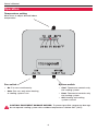
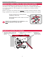
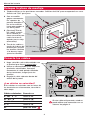
1
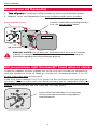
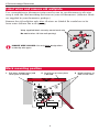
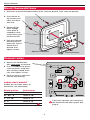
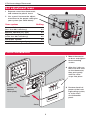
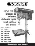
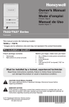
Owner’s
Manual
CT31
Low-voltage Thermostat
Getting started
Check to make sure your package includes the following items:
Wire labels
Caution card
Wall anchors and
mounting screws
(2 each)
CT31 thermostat
Cover plate
Before you begin, make sure you have:
• Screwdriver
• Hammer
• Level (optional)
• Pencil
• Drill bit (3/16” for drywall, 7/32” for plaster)
® U.S. Registered Trademark. Patents pending.
Copyright © 2005 Honeywell International Inc.
All rights reserved.
Owner’s Manual
Remove your old thermostat
1 Turn off power at heating/cooling system (or fuse/circuit-breaker panel).
2 Remove cover and thermostat, but leave wallplate with wires attached.
Leave wallplate in place
Is there a sealed tube containing mercury?
If so, see mercury notice below.
Old thermostat
Cover
MERCURY NOTICE: Do not place your old thermostat in the trash if it contains
mercury in a sealed tube. Contact your local waste management authority for
instructions regarding recycling and proper disposal.
Did you purchase right thermostat? Count wires to check.
Count the number of wires coming out of the wall and attached to terminals in
your old thermostat. If any of them are attached to a terminal marked “C” or “C1”
do not count that wire in your total.
If the total (not counting C or C1) is 4 wires or less, proceed to the next page. If
you have 5 or more wires, your new thermostat may not be compatible with your
system. Stop installation and call 1-800-468-1502 for advice.
Do you have 5 or more wires? If so, stop now.
You may have purchased the wrong replacement thermostat.
2
CT31 Low-voltage Thermostat
Label wires and remove old wallplate
Use a screwdriver to disconnect wires one by one.As you disconnect each wire,
wrap it with the label matching the letter on your old thermostat. (Adhesive labels
are supplied in your thermostat package.)
Remove the old wallplate only after all wires are labeled. Be careful not to let
loose wires fall into the wall opening.
Wrap supplied labels securely around each wire
Do not let wires fall into wall opening!
IGNORE WIRE COLORS: Use only letter designations
to identify wire types.
Mark mounting position
1 Pull wires through base (and
cover plate if desired).
2 Level base or cover plate
if desired.
3
3 Mark positions of
both screw holes.
Owner’s Manual
Mount thermostat base
1 Drill holes at pencil-marked locations (3/16” holes for drywall, 7/32” holes for plaster).
2 Use hammer to
tap anchors into
holes until flush
with wall.
3 [Optional] Pull
wires through
cover plate (if
needed to cover
marks left by your
old thermostat).
4 Pull wires through
thermostat base
and insert screws.
Check level if
desired, then
tighten screws.
Optional cover plate
Thermostat base
Connect wires
1 Match each labeled wire
with same letter on terminal.
2 Use a screwdriver to loosen
screw terminals, wrap bare
wire securely around terminals, then tighten screws.
3 Push any excess wire back
into the wall opening.
Labels don’t match?
If labels do not match letters on
thermostat, see table below.
Existing wires
Connect to:
R • RH • 4 • V
Terminal “R”
W • W1 • H
Terminal “W”
Y • Y1 • M
Terminal “Y”
G•F
Terminal “G”
Rc
Stop! See note
If this wire is present, you cannot use
this thermostat with your system. See
page 2.
4
CT31 Low-voltage Thermostat
Set adjustment lever
1 Separate cover from thermostat,
and remove the plastic insert.
2 Use a pencil to move the adjustment lever to the proper setting for
your system (see table below).
Your system
Setting
Gas or oil furnace
(less than 90% efficiency)
0.4
Electric furnace (any type)
0.3
High efficiency furnace
(more than 90% efficiency)
0.8
Hot water system
0.8
Gas/oil steam or gravity system
1.2
Finish installation
1 Mount thermostat
on base and tighten
three mounting
screws.
2 Align the 3 tabs on
the cover with slots
on the thermostat,
then push gently
until the cover
snaps into place.
Base
(shown with
optional
cover plate)
3 Restore electrical
power at the heating/cooling system,
or at the fuse/
circuit-breaker
panel.
Thermostat
Cover
5
Owner’s Manual
Operation
Temperature setting
Move lever to adjust desired indoor
temperature.
Fan switch
System switch
•
On: Fan runs continuously.
•
•
Auto: Fan runs only when heating
or cooling system is on.
Cool: Thermostat controls only
the cooling system.
•
Heat: Thermostat controls only
the heating system.
•
Off: Heating and cooling
systems are off.
CAUTION: EQUIPMENT DAMAGE HAZARD. To prevent possible compressor damage,
do not operate cooling system when outdoor temperature is below 50°F (10°C).
6
CT31 Low-voltage Thermostat
Limited Warranty
Honeywell warrants this product to be free from defects in the workmanship or
materials, under normal use and service, for a period of one (1) year from the date
of purchase by the consumer. If at any time during the warranty period the product is determined to be defective or malfunctions, Honeywell shall repair or
replace it (at Honeywell's option).
If the product is defective,
(i) return it, with a bill of sale or other dated proof of purchase, to the place from
which you purchased it; or
(ii) call Honeywell Customer Care at 1-800-468-1502. Customer Care will make the
determination whether the product should be returned to the following address:
Honeywell Return Goods, Dock 4 MN10-3860, 1885 Douglas Dr. N., Golden Valley,
MN 55422, or whether a replacement product can be sent to you.
This warranty does not cover removal or reinstallation costs.This warranty shall
not apply if it is shown by Honeywell that the defect or malfunction was caused
by damage which occurred while the product was in the possession of a
consumer.
Honeywell's sole responsibility shall be to repair or replace the product
within the terms stated above. HONEYWELL SHALL NOT BE LIABLE FOR ANY
LOSS OR DAMAGE OF ANY KIND, INCLUDING ANY INCIDENTAL OR CONSEQUENTIAL DAMAGES RESULTING, DIRECTLY OR INDIRECTLY, FROM ANY
BREACH OF ANY WARRANTY, EXPRESS OR IMPLIED, OR ANY OTHER FAILURE OF
THIS PRODUCT. Some states do not allow the exclusion or limitation of incidental
or consequential damages, so this limitation may not apply to you.
THIS WARRANTY IS THE ONLY EXPRESS WARRANTY HONEYWELL MAKES ON
THIS PRODUCT.THE DURATION OF ANY IMPLIED WARRANTIES, INCLUDING
THE WARRANTIES OF MERCHANTABILITY AND FITNESS FOR A PARTICULAR
PURPOSE, IS HEREBY LIMITED TO THE ONE-YEAR DURATION OF THIS
WARRANTY. Some states do not allow limitations on how long an implied
warranty lasts, so the above limitation may not apply to you.
This warranty gives you specific legal rights, and you may have other rights which
vary from state to state.
If you have any questions concerning this warranty, please write Honeywell
Customer Relations, 1985 Douglas Dr, Golden Valley, MN 55422 or call 1-800-4681502. In Canada, write Retail Products ON15-02H, Honeywell Limited/
Honeywell Limitée, 35 Dynamic Drive, Scarborough, Ontario M1V4Z9.
7
Need Help?
For assistance with this product please visit www.honeywell.com/yourhome
or call Honeywell Customer Care toll-free at 1-800-468-1502
Automation and Control Solutions
Honeywell International Inc.
Honeywell Limited-Honeywell Limitée
1985 Douglas Drive North
35 Dynamic Drive
Golden Valley, MN 55422
Scarborough, Ontario M1V 4Z9
www.honeywell.com/yourhome
Printed in U.S.A. on recycled
paper containing at least 10%
post-consumer paper fibers.
® U.S. Registered Trademark.
© 2005 Honeywell International Inc.
Patents pending. All rights reserved.
69-1809ES Rev. 03-2005
Manual del
usuario
CT31
Termostato de bajo voltaje
Lista de comprobación previa a la instalación
Asegúrese de que el paquete contenga los siguientes elementos:
Rótulos para los cables
Termostato CT31
La placa de cubierta
Tarjeta de
advertencia
Soportes de pared y
tornillos de montaje
(2 cada uno)
Herramientas y materiales necesarios
• Destornillador
• Martillo
• Nivel (optativo)
• Lápiz
• Mecha de taladro (3/16” para mampostería en seco, 7/32” para yeso)
® Marca registrada en EE.UU. Patentes pendientes.
Copyright © 2005 Honeywell International Inc.
Todos los derechos reservados.
Manual del usuario
Remueva su viejo termostato
1 Desconecte la alimentación en el sistema de calefacción/refrigeración (o en el
panel de fusibles/disyuntor).
2 Retire la cubierta y el termostato,pero deje los cables unidos a la placa de montaje.
Deje la placa de montaje en su lugar
¿Existe algún tubo sellado que contenga
mercurio? Si es así, consulte el aviso sobre
mercurio que figura abajo.
Termostato viejo
Cubierta
AVISO DE MERCURIO: No arroje su viejo termostato a la basura si contiene mercurio
en un tubo sellado. Comuníquese con la autoridad local de disposición de desechos
para recibir instrucciones sobre reciclado y eliminación correcta..
¿Compró el termostato correcto? Cuente los cables.
Cuente los cables que salen de la pared y están conectados a los terminales de su
viejo termostato. Si cualquiera de ellos está conectado a un terminal marcado “C”o
“C1” no lo cuente.
Si el total (sin contar C o C1) es de 4 cables o menos, continúe con la página
siguiente. Si hay 5 cables o más, es posible que su nuevo termostato no sea
compatible con su sistema. Interrumpa la instalación y llame al 1-800-468-1502
para pedir consejo.
¿Hay 5 o más cables? Si es así, deténgase
ahora. Es posible que haya comprado el
termostato de reemplazo incorrecto.
2
Termostato de bajo voltaje CT31
Rotule los cables y retire la vieja placa de montaje
Use un destornillador para desconectar los cables uno a uno.A medida que
desconecte cada cable, péguele alrededor el rótulo con la misma letra que figura
en su viejo termostato. (En el paquete de su termostato se incluyen rótulos
autoadhesivos.)
Retire la vieja placa de montaje sólo después de haber rotulado todos los cables.
Tenga cuidado de no dejar que los cables sueltos caigan en el hueco de la pared.
Envuelva firmemente los rótulos provistos
alrededor de cada cable
¡No permita que los cables caigan en el hueco
de la pared!
IGNORE LOS COLORES DE LOS CABLES: Use sólo
letras para identificar los tipos de cable.
Repérez la position de montage
1 Tire de los cables a través de
la base (y de la cubierta si lo
desea).
2 Nivele la base o la cubierta si
lo desea.
3
3 Marque las
posiciones de
ambos orificios.
Manual del usuario
Coloque la placa de montaje
1 Taladre orificios en las posiciones marcadas. Orificios de 3/16” para mampostería en seco.
Orificios de 7/32” para yeso.
2 Con un martillo
golpee suavemente
los soportes de
pared e introdúzcalos en los orificios
hasta que queden al
ras de la pared.
3 [Opcional] Tire de
los cables a través
de la cubierta (si
fuese necesario para
cubrir las marcas
dejadas por su viejo
termostato).
4 Tire de los cables a
través de la base del
termostato e inserte
los tornillos. Nivélela
si lo desea y luego
ajuste los tornillos.
Cubierta opcional
Termostato
Conecte los cables
1 Haga coincidir cada cable rotulado con
el terminal que tiene la misma letra.
2 Utilice un destornillador para aflojar los
terminales atornillados, enrosque
firmemente el cable pelado alrededor
de los terminales, luego ajuste los
tornillos.
3 Empuje el cable sobrante dentro del
orificio de la pared.
¿Los rótulos no coinciden?
Si los rótulos no coinciden con las letras de
los terminales en el termostato, consulte la
tabla abajo.
Cables existentes Conecte a:
R • RH • 4 • V
Terminal “R”
W • W1 • H
Terminal “W”
Y • Y1 • M
Terminal “Y”
G•F
Terminal “G”
Rc
¡Alto! Ver nota.
Si este cable está presente, usted no
puede utilizar este termostato con su
sistema. Ver página 2.
4
Termostato de bajo voltaje CT31
Coloque la palanca de ajuste en posición
1 Separe la cubierta del termostato y
retire la lámina de plástico
2 Con un lápiz mueva la palanca de
ajuste hasta la posición apropiada
para su sistema. (Ver tabla a
continuación).
Su sistema
Ajuste
Estufa de gas o petróleo
(menos del 90% de eficiencia)
0.4
Estufa eléctrica (cualquier tipo)
0.3
Estufa de alta eficiencia
(más del 90% de eficiencia)
0.8
Sistema de agua caliente
0.8
Sistema de vapor a petróleo
o de gravedad/gas
1.2
Finalice la instalación
1 Monte el termostato
en la base y ajuste
los tres tornillos de
montaje.
2 Alinee las 3
lengüetas de la
cubierta con las
ranuras del
termostato, luego
empuje con
suavidad hasta que
la cubierta calce en
su lugar.
Base (se
muestra con
la cubierta
opcional)
3 Vuelva a conectar la
corriente eléctrica
en el sistema de
calefacción/
refrigeración, o en el
panel de fusibles/
disyuntor.
Termostato
Cubierta
5
Manual del usuario
Instrucciones de manejo
Ajuste de temperatura
Mueva la palanca para ajustar la
temperatura deseada en el interior.
Interruptor del ventilador
Interruptor del sistema
On: El ventilador funciona continuamente.
Auto: Funciona sólo cuando está encendido el
sistema de refrigeración o calefacción.
•
Cool: Termostato controla sólo
el sistema de refrigeración.
•
Heat: Termostato controla sólo
el sistema de calefacción.
•
Off: Sistemas de calefacción y
refrigeración apagados.
PRECAUCIÓN: PELIGRO DE DAÑO AL EQUIPO. Para impedir un posible daño al
compresor, no haga funcionar el sistema de refrigeración cuando la temperatura exterior
sea inferior a 50°F (10°C).
6
Termostato de bajo voltaje CT31
Garantía limitada
Honeywell garantiza que, a excepción de la batería y en condiciones de uso y
servicio normales, este producto no tendrá defectos de fabricación ni de materiales durante un (1) año a partir de la fecha de compra por parte del consumidor.
Si durante ese período de garantía, el producto resulta defectuoso o tiene
problemas de funcionamiento, Honeywell lo reparará o reemplazará (a criterio
de Honeywell).
Si el producto es defectuoso:
(i) devuélvalo, acompañado de la factura u otra prueba de compra con fecha, al
lugar donde lo adquirió; o
(ii) llame al numéro de atención al cliente de Honeywell al 1-800-468-1502.
Atención al cliente determinará si el producto se debe devolver a la siguiente
dirección: Honeywell Return Goods, Dock 4 MN10-3860, 1885 Douglas Dr. N.
Golden Valley, MN 55422 o bien, si se le puede enviar un producto de reemplazo.
Esta garantía no cubre los costos de remoción o reinstalación. Esta garantía no
corresponde si Honeywell prueba que el defecto o mal funcionamiento ha sido
ocasionado por daño producido mientras el producto estaba en manos de un
consumidor.
La única responsabilidad de Honeywell será reparar o reemplazar el producto en
el marco de los términos precedentemente mencionados. HONEYWELL NO SERÁ
RESPONSABLE POR NINGUNA PÉRDIDA NI DAÑOS DE NINGÚN TIPO, INCLUSO
DAÑOS INCIDENTALES O CONSECUENTES QUE RESULTEN, DIRECTA O
INDIRECTAMENTE DEL INCUMPLIMIENTO DE CUALQUIER GARANTÍA, EXPRESA
O IMPLÍCITA, O DE NINGUNA OTRA FALLA DE ESTE PRODUCTO.Algunos
estados no admiten la exclusión o limitación de los daños incidentales o
consecuentes, de manera que tal vez esta limitación no se aplique en su caso.
ÉSTA ES LA ÚNICA GARANTÍA EXPRESA DE HONEYWELL RESPECTO DE ESTE
PRODUCTO. LA DURACIÓN DE LAS GARANTÍAS IMPLÍCITAS, INCLUSO LA DE
COMERCIABILIDAD Y DE APTITUD PARA UN USO PARTICULAR, SE LIMITA POR
ELLO A LA DURACIÓN DE UN AÑO DE ESTA GARANTÍA.Algunos estados no
admiten limitaciones en cuanto a la duración de las garantías implícitas, de manera
que tal vez la limitación precedente no se aplique en su caso.
Esta garantía le otorga derechos legales específicos y puede gozar de otros
derechos que varían de un estado al otro.
Si desea consultar acerca de esta garantía, escriba a Honeywell Customer
Relations, 1985 Douglas Dr, Golden Valley, MN 55422 o llame a 1-800-468-1502.
En Canadá, escriba a Retail Products ON15-02H Honeywell Limited/ Honeywell
Limitée, 35 Dynamic Drive, Scarborough, Ontario M1V4Z9.
7
¿Necesita ayuda?
Consulte sobre este producto en www.honeywell.com/yourhome
o llamando sin cargo a atención al cliente de Honeywell 1-800-468-1502
Automation and Control Solutions
Honeywell International Inc.
Honeywell Limited-Honeywell Limitée
1985 Douglas Drive North
35 Dynamic Drive
Golden Valley, MN 55422
Scarborough, Ontario M1V 4Z9
www.honeywell.com/yourhome
Impreso en EE.UU. en papel reciclado
que contiene, por lo menos, un 10%
de papel ya usado.
® Marca registrada en EE.UU.
© 2005 Honeywell International Inc.
Patentes pendientes. Todos los derechos reservados.
69-1809ES Rev. 03-2005