1
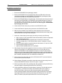
PRO-2200
Power Supply With Battery Backup*
Installation Manual
Part Number: PRO22E1PS
* 4 amp hour and 7 amp hour backup battery sold separately.
TD1140 rev0401
2
Installation Guide
PRO-2200 Power Supply With Battery Backup PRO22E1PS
PRO-2200 Power Supply With Battery Backup PRO22E1PS
Installation Guide
3
Contents
Warnings and Cautions .........................................................................................4
Disclaimer .............................................................................................................6
Product Liability; Mutual Indemnification ...............................................................6
Unpacking Procedure ...........................................................................................6
Shipping Instructions ............................................................................................7
Limited Warranty ...................................................................................................7
Confidentiality .......................................................................................................8
PRO2200 Enclosure .............................................................................................9
Description ............................................................................................................9
Dimensions .........................................................................................................10
Power Supply ......................................................................................................10
Notes ..................................................................................................................11
Installation Instructions ........................................................................................12
Installation Diagram ............................................................................................13
Cable Specifications ...........................................................................................14
NCI Cable Part Numbers ....................................................................................15
4
Installation Guide
PRO-2200 Power Supply With Battery Backup PRO22E1PS
Warnings and Cautions
WARNING
Before installation, TURN OFF the external circuit breaker which supplies power to the
system.
Before connecting the device to the power supply, verify that the output voltage is within
specifications of the power supply.
Do not apply power to the system until after the installation has been completed.
Personal injury or death could occur, and the equipment could be damaged beyond repair
if this precaution is not observed!
WARNING
Fire Safety and Liability Notice
Never connect card readers to any critical entry, exit door, barrier, elevator or gate without
providing an alternative exit in accordance with all fire and life safety codes pertinent to
the installation. These fire and safety codes vary from city to city and approval from local
fire officials is required whenever using an electronic product to control a door or other
barrier. Use of egress buttons, for example, may be illegal in some cities. In most applications, single action exit without prior knowledge of what to do is a life safety requirement.
Always make certain that any required approvals are obtained in writing. DO NOT ACCEPT VERBAL APPROVALS, AS THEY ARE NOT VALID.
Northern never recommends using the PRO-2200 or related products as a primary warning
or monitoring system. Primary warning or monitoring systems should always meet local
fire and safety code requirements. The installer must test the system on a regular basis
and instruct the end user in appropriate daily testing procedures. Failure to test a system
regularly could make installer liable to the end user for damages if a problem occurs.
WARNING
EARTH ground all enclosures, for proper installation.
EARTH ground can be obtained through the power supply or by grounding the cabinet,
BUT NOT BOTH!
WARNING
Use suppressors on all door strikes. Use S-4 suppressors for installation. Northern
Computers recommends only DC strikes.
The information in this document is subject to change without notice.
PRO-2200 Power Supply With Battery Backup PRO22E1PS
Installation Guide
5
CAUTION
IF ANY DAMAGE TO THE SHIPMENT IS NOTICED, A CLAIM MUST BE FILED WITH
THE RESPONSIBLE COMMERCIAL CARRIER.
CAUTION
Electro-static discharge can damage CMOS integrated circuits and modules.
To prevent damage always follow these procedures:
Use static shield packaging and containers to transport all electronic components,
including completed reader assemblies.
Handle all ESD sensitive components at an approved static controlled workstation. These
workstations consist of a desk mat, floor mat and an ESD wrist strap. Workstations are
available from various vendors.
NOTICE
THIS EQUIPMENT HAS BEEN TESTED AND FOUND TO COMPLY WITH THE LIMITS
FOR A CLASS A DIGITAL DEVICE, PURSUANT TO PART 15 OF THE FCC RULES
WHEN WIRED USING METAL CONDUIT FOR THE CABLING EXTERNAL TO THE
ENCLOSURE. THESE LIMITS ARE DESIGNED TO PROVIDE REASONABLE PROTECTION AGAINST HARMFUL INTERFERENCE WHEN THE EQUIPMENT IS OPERATED
IN A COMMERCIAL ENVIRONMENT. THIS EQUIPMENT GENERATES, USES, AND
CAN RADIATE RADIO FREQUENCY ENERGY AND, IF NOT INSTALLED AND USED
IN ACCORDANCE WITH THE INSTRUCTION MANUAL, MAY CAUSE HARMFUL
INTERFERENCE TO RADIO COMMUNICATIONS. OPERATION OF THIS EQUIPMENT
IN A RESIDENTIAL AREA IS LIKELY TO CAUSE HARMFUL INTERFERENCE IN
WHICH CASE THE USER WILL BE REQUIRED TO CORRECT THE INTERFERENCE
AT HIS OWN EXPENSE.
NOTICE
This document and the data in it shall not be duplicated, used or disclosed to others for
procurement or manufacture, except as authorized by and with the written permission of
Northern Computers, Inc. The information contained in this document or in the product
itself is considered the exclusive property and trade secrets of Northern Computers, Inc.
Copyright laws of the United States protect all information in this document or in the
software product itself.
NOTICE
Any use of this product is subject to the terms and acceptance of the Northern
Computers, Inc. Software Agreement. Please request a copy from Northern Computers,
Inc., and review the agreement carefully.
6
Installation Guide
PRO-2200 Power Supply With Battery Backup PRO22E1PS
Disclaimer
Product Liability; Mutual Indemnification
In the event that a Customer receives a claim that a Product or any component thereof
has caused personal injury or damage to property of others, Customer shall immediately
notify Northern in writing of all such claims. Northern shall defend or settle such claims
and shall indemnify and hold Customer harmless for any costs or damages including
reasonable attorneys’ fees which Customer may be required to pay as a result of the
defective Product or the negligence of Northern, its agents, or its employees.
Customer shall hold harmless and indemnify Northern from and against all claims,
demands, losses and liability arising out of damage to property or injury to persons
occasioned by or in connection with the acts or omissions of Customer and its agents
and employees, and from and against all claims, demands, losses and liability for costs of
fees, including reasonable attorneys’ fees, in connection therewith.
Unpacking Procedure
CAUTION
If any damage to the shipment is noticed before unpacking, a claim must be filed with the
commercial carrier.
All containers should be opened and unpacked carefully in order to prevent damage to the
contents.
The following steps are used to unpack equipment in preparation for installation:
1. Open the container and remove the unit(s) and all packing material. Retain the
container and all packing materials; it may be used again for reshipment
of the equipment, if needed.
2. Inspect the contents for shortage. If items are missing, contact the order entry
department at 800-323-4576.
3. Visually check contents. If damage is discovered, perform the following:
If shipping caused damage to the unit, a claim must be filed with the
commercial carrier.
If any other defect is apparent, call for a return authorization at 800-323-4576.
PRO-2200 Power Supply With Battery Backup PRO22E1PS
Installation Guide
7
Shipping Instructions
To ship equipment back to Northern Computers, Inc.:
1. Contact the customer service department before returning equipment at 800-323-4576.
Please have the following available when calling:
• A description of the problem or reason equipment is being returned.
• Original purchase order number, invoice number and warranty information - if the
unit is still under warranty.
• A new purchase order number if the unit is not under warranty
2. Obtain the Return Authorization Number (RMA) from the customer service
department.
3. Show the RMA number on all packages shipped. Packages, which are not marked with
an RMA number will be refused at the factory and returned COD.
4. Carefully pack the equipment for shipment. Use the original packing material whenever
possible.
Limited Warranty
All Products sold or licensed by Northern include a warranty registration card which must
be completed and returned to Northern by or on behalf of the end user in order for
Northern to provide warranty service, repair, credit or exchange. All warranty work shall
be handled through Customer which shall notify Northern and apply for a Return
Merchandise Authorization (RMA) number prior to returning any Product for service, repair,
credit or exchange. Northern warrants that its Products shall be free from defects in
materials and workmanship for a period of two years from date of shipment of the Product to Customer. The warranty on Terminals, Printers, Communications Products and
Upgrade kits is 90 days from date of shipment. Satisfaction of this warranty shall be
limited to repair or replacement of Products which are defective or defective under
normal use. Northern’s warranty shall not extend to any Product which, upon
examination, is determined to be defective as a result of misuse, improper storage,
incorrect installation, operation or maintenance, alteration, modification, accident or
unusual deterioration of the Product due to physical environments in excess of the limits
set forth in Product manuals. THERE ARE NO WARRANTIES WHICH EXTEND BEYOND
THIS PROVISION. THIS WARRANTY IS IN LIEU OF ALL OTHER WARRANTIES
WHETHER EXPRESS, IMPLIED OR STATUTORY, INCLUDING IMPLIED WARRANTIES
OF MERCHANTABILITY OR FITNESS FOR ANY PARTICULAR PURPOSE. NO REPRESENTATION OR WARRANTY OF THE DISTRIBUTOR SHALL EXTEND THE LIABILITY
OR RESPONSIBILITY OF THE MANUFACTURER BEYOND THE TERMS OF THIS
PROVISION. IN NO EVENT SHALL NORTHERN BE LIABLE FOR ANY
RE-PROCUREMENT COSTS, LOSS OF PROFITS, LOSS OF USE, INCIDENTAL,
CONSEQUENTIAL OR SPECIAL DAMAGES TO ANY PERSON RESULTING FROM THE
USE OF NORTHERN’S PRODUCTS.
8
Installation Guide
PRO-2200 Power Supply With Battery Backup PRO22E1PS
Confidentiality
All software, drawings, diagrams, specifications, catalogs, literature, manuals and other
materials furnished by Northern relating to the design, use and service of Products shall
remain confidential and shall constitute proprietary rights of Northern, and Customer
agrees to treat such information as confidential. Customer shall acquire no rights in the
design of Products or the related materials except to use such information solely for the
purpose of and only during the time it sells Products. Customer shall not copy the design
of any Products or use or cause to be used any Product design or related materials for its
own benefit or for the benefit of any other party. The covenants contained in this section
shall remain effective throughout the term of this Agreement and thereafter unless specifically waived by Northern in writing.
PRO-2200 Power Supply With Battery Backup PRO22E1PS
Installation Guide
9
PRO-2200 Enclosure
Description
The PRO22E1PS is a 4 amp power supply with battery backup control. The unit mounts in
the PRO22ENC1, PRO22ENC2 or the PRO22ENC5 by sliding the unit vertically into the
right most card guide. The PRO22E1PS can be wired to the PRO-2200 I/O with the selfcontained cabling. The unit can supply up to 4 amps to the 9 panels used in the PRO2200 enclosure system. When used with the PRO22DCC daisy chain for communication
and power distribution, the PRO22E1PS becomes an easy to wire power system.
The PRO22E1PS is capable of supplying a charging current to a 4 amp hour, 7 amp hour
or larger 12 VDC sealed battery purchased separately. The power supply controls inputs
for AC Fail and Battery Fail. There is a Power On light located conveniently near the AC
cord inlet.
10
Installation Guide
PRO-2200 Power Supply With Battery Backup PRO22E1PS
Dimensions
Height:
Width:
Depth:
9"
5.5"
2.2"
Power Supply
•
12 VDC 4 amp continuous power limited output with backup battery charging and
battery supervision
•
The power supply is not rated for lock power
•
The power supply can accept 85 VAC to 230 VAC at 50/60 hz
•
110 VAC/60 hz .5 amp
•
220 VAC/50 hz .25 amp
•
Maximum battery charging current .5 amp
•
AC on LED
•
AC Fail supervision when connected to PRO22IC or other PRO-2200 I/O at PFL
(Power Fail) input
•
Low battery supervision when connected to an auxiliary input
•
Short circuit and thermal overload protection with self-resetting poly fuses
•
All power connections should be made with 18ga wire or larger wiring
PRO-2200 Power Supply With Battery Backup PRO22E1PS
NOTES
Installation Guide
11
12
Installation Guide
PRO-2200 Power Supply With Battery Backup PRO22E1PS
Installation Instructions
1. Remove the PRO22E1PS from packaging material.
2. Remove the PRO22E1PL from the plastic bag. Place the LED end into the small
round hole at the bottom of the PRO22ENC1 or PRO22ENC2 (see diagram). Make
sure that the red LED is to the outside of the enclosure.
3. Remove the PRO22E1PO from the plastic bag. Feed the cable into the square hole at
the bottom of the PRO22ENC1 or PRO22ENC2 (see installation diagram on page 13).
It is important to make sure that the AC inlet will be facing out of the enclosure and
the enclosed power cord will be facing toward the rear when plugged in. Do Not Power
Up The Supply At This Time.
4. Connect the AC Power three prong connector to the PRO22E1PO cable.
5. Connect the Power On light two prong connector to the PRO22E1PL cable.
6. Make sure the remainder of the cables are pulled towards the front of the power
supply and that the AC and Power On light do not bind behind the power supply. Slide
the PRO22E1PS into the right-most card guide.
7. At this time, insure that the power supply is working correctly by the following:
a. Make sure the 12 VDC red and black cable ends and battery cables are separated
and not touching any metal.
b. Plug the PRO22E1PS into the supplied power cord and into a wall socket.
c. Check the voltage at the 12 VDC power cable to insure it is between 13.6 and
14.0 VDC
d. Check the battery cables to insure that they are also between 13.6 and 14.0 VDC.
e. Check that the red Power On LED is lit.
f. UNPLUG THE POWER SUPPLY AT THIS TIME!!!
8. After disconnecting the power supply from the source, wire the 12 VDC to the PRO2200 I/O. The red wire is +12 VDC and the black wire is -12 VDC. Wire all I/O in
parallel. The PRO22DCC is also available as an option. Connect the power supply
cables to the daisy chain and the RS485 communications and the 12 VDC power will
be wired for the I/O. See individual panel installation manual for additional details. DO
NOT POWER THE PANELS UNTIL ALL WIRING IS COMPLETE!
9. Wire the Power Fail cable white wire into the PRO-2200 I/O PFL input and the black
wire into the common for that input.
10. Wire the Battery Fail cable to an auxiliary input and rename the input using front end
software WIN PAK PRO Release 3 with service pack 1 or higher.
11. Wire the grounding cable to the grounding stud. The enclosure may be grounded using
the power supply or a separate ground wire, BUT NOT BOTH!
12. Connect the battery cables to the backup battery if required. The red cable connects
to the positive (+) terminal on the battery and the black cable to the negative (-)
terminal of the battery. Connect only the red positive battery cable at this time.
Connect the black negative cable when the power supply is powered up. The battery
may be placed directly in front of the power supply for a 4 amp hour or 7 amp hour
battery. The battery may also be placed above the card rack if wiring allows.
PRO-2200 Power Supply With Battery Backup PRO22E1PS
Installation Guide
13. CHECK ALL WIRING BEFORE POWERING UP THE PRO22E1PS. Unrepairable
damage could result from improper wiring. Power up the PRO22E1PS. All panels
connected should go through their particular start up sequence. See individual
installation manuals for more detail.
Installation Diagram
Front View
Bottom View
13
14
Installation Guide
PRO-2200 Power Supply With Battery Backup PRO22E1PS
Cable Specifications
Application
NCI Part No.
AWG
Description
Max. Dist.
Imp.
4000' (1200 m)
120Ω 12.8pf/ft
N-485 connections
NC2442-TN
N/A
N/A
Belden 9842
or equivalent
CR-1, TR-1, CI-1, KR-1
Wiegand card readers
NC1861-BL
18
6 conductor shielded
500' (152 m)
NR-1 magstripe reader
NC1861-BL
18
6 conductor shielded
500' (152 m)
PR-1-280 Cotag reader:
280 read head to SZC
SZC to N-1000-II
NC1861-BL
NC1861-BL
18
18
6 conductor shielded
6 conductor shielded
300' (91 m)
500' (152 m)
PR-2 Hughes reader:
scanner to reader
reader to N-1000-II
NC1861-BL
NC1861-BL
18
18
6 conductor shielded
6 conductor shielded
30' (9 m)
500' (152 m)
PR-3, PR-5 Indala readers:
A-3/A-5 read head to RE-2
RE-2 to N-1000-II
NC18121-YL
NC1861-BL
18
18
12 conductor shielded
6 conductor shielded
75' (23 m)
500' (152 m)
PR-20 , PR-22 Indala readers:
A-20/A-22 read head
to RE-2
NC18121-YL
RE-2 to N-1000-II
NC1861-BL
18
18
12 conductor shielded
6 conductor shielded
75' (23 m)
500' (152 m)
PR-10, PR-12 Indala readers: NC1861-BL
18
6 conductor shielded
500' (152 m)
HG-3 hand geometry reader: NC1861-BL
18
6 conductor shielded
500' (152 m)
5 conductor keypad
NC1861-BL
18
6 conductor shielded
500' (152 m)
Alarm input points
NC 2221-BR
22
2000' (610 m)
Relay outputs
NC 1821-OR
18
twisted pair, shielded
Cap.
2000' (610 m)
NOTE: For Plenum rated cable just add a “P” to Northern’s part number prefix; for example NC1861-BL
becomes PNC1861-BL
PRO-2200 Power Supply With Battery Backup PRO22E1PS
Installation Guide
15
NCI Cable Part Numbers
Part Number
Description
Application
Length
NC1841-GY
18 AWG/4 conductor
reader cable
1,000'
NC1861-BL-500
18 AWG/6 conductor
reader cable
500'
NC1861-BL
18 AWG/6 conductor
reader cable
1,000'
NC18121-YL-500
18 AWG/12 conductor
keypad cable
500'
NC18121-YL
18 AWG/12 conductor
keypad cable
1,000'
NCNET-1
50 ohm
network cable
1,000'
NC2221-BR
22 AWG/2 conductor
alarm cable
1,000'
NC1821-OR
18 AWG/2 conductor
power/door cable
1,000'
NCC59206-BK
RG-59
video cable
1,000'
NCP1841-GY
18 AWG/4 conductor Plenum
reader cable
1,000'
NCP1861-BL-500
18 AWG/6 conductor Plenum
reader cable
500'
NCP1861-BL
18AWG/6 conductor Plenum
reader cable
1,000'
NCP18121-YL
18 AWG/12 conductor Plenum
keypad cable
1,000'
NCP18121-YL-500
18 AWG/12 conductor Plenum
keypad cable
500'
NCPNET-1
50 ohm Plenum
network cable
1,000'
NCP2221-BR
22 AWG/2 conductor Plenum
alarm point cable
1,000'
NCP1821-OR
8 AWG/2 conductor Plenum
power/door cable
1,000'
NC2442-TN
24 AWG/120Ω12.8pf RS485 wire
communication cable
1,000'
NCP2442-TN
24 AWG/120Ω12.8pf RS485 wire
communication cable
1,000'
Honeywell Security & Data Collection
2700 Blankenbaker Pkwy, Suite 150
Louisville, KY 40299
(800) 675-3364
www.honeywellaccess.com