1
NetAXS™
NX4L1
Access Control Unit
Installation Guide
May 15, 2007
© 2007 Honeywell. All rights reserved.
7-901099, Revision A
Copyright© 2007 Honeywell. All rights reserved.
All product and brand names are the service marks, trademarks, registered trademarks,
or registered service marks of their respective owners. Printed in the United States of
America. Honeywell reserves the right to change any information in this document at
any time without prior notice.
Ordering Information
Please contact your local Honeywell representative or visit us on the web at
www.honeywellaccess.com for information about ordering.
Feedback
Honeywell appreciates your comments about this manual. Please visit us on the web at
www.honeywellaccess.com to post your comments.
CONTENTS
NetAXS™ NX4L1 Installation
1.0 Notices .................................................................................................................................................. 1
1.1 Warnings and Cautions ...................................................................................................... 1
1.2 Product Liability, Mutual Indemnification ........................................................................ 2
1.3 Limited Warranty............................................................................................................... 2
1.4 Federal Communications Commission .............................................................................. 3
1.5 Industry Canada ................................................................................................................. 3
1.6 Underwriters Laboratories Incorporated............................................................................ 4
2.0 Introduction .......................................................................................................................................... 5
2.1 Access Control Overview .................................................................................................. 5
2.2 NetAXS™ Access Overview............................................................................................. 5
3.0 Panel Components and Descriptions................................................................................................ 6
3.1 NetAXS™ Access Control Unit ........................................................................................ 7
Real-Time Clock Protection ............................................................................................ 7
Memory Protection .......................................................................................................... 7
Reader and AUX Power .................................................................................................. 7
3.2 Power Supply ..................................................................................................................... 8
3.3 Batteries ............................................................................................................................. 8
3.4 Enclosure ........................................................................................................................... 8
3.5 Suppressors ........................................................................................................................ 8
4.0 Installation............................................................................................................................................ 9
4.1 Installing the Optional AC Inlet....................................................................................... 10
4.2 Tying the Field Wiring in the NX4L1 Cabinet................................................................ 11
4.3 Cabinet Mounting ............................................................................................................ 12
4.4 Reader Wiring.................................................................................................................. 16
4.5 Supervised Input Wiring .................................................................................................. 17
4.6 NX4L1 Control Output Wiring........................................................................................ 18
4.7 Communications .............................................................................................................. 21
RS-232 Communications .............................................................................................. 21
RS-485 Communications .............................................................................................. 22
Ethernet TCP/IP Communications ................................................................................ 24
NetAXS Access Control Unit NX4L1 Installation Guide, Document 7-901099, Revision A
iii
4.8 DIP Switch Settings ......................................................................................................... 26
4.9 Jumper Settings................................................................................................................ 28
4.10 Downstream I/O............................................................................................................. 28
5.0 System Configuration ....................................................................................................................... 31
5.1 RS-485 Connection via PCI-2 ......................................................................................... 31
5.2 RS-485 Connection via NetAXS™ ................................................................................. 32
5.3 RS-485 Connections with Multidrop Panels at Both Ends of the Cable ......................... 33
5.4 RS-232 Connection.......................................................................................................... 35
5.5 Ethernet Connection ........................................................................................................ 36
5.6 LANSRLU1 Connection.................................................................................................. 37
5.7 RS-485 Short Haul Modem Connection via PCI-2 ......................................................... 38
5.8 RS-485 Short Haul Modem Connection via NetAXS™ ................................................. 39
5.9 RS-232 Short Haul Modem Connection .......................................................................... 40
5.10 M-56K Dial-up Modem, RS-485 Connection via Hub.................................................. 41
5.11 M-56K Dial-up Modem, RS-485 Connection via NetAXS™....................................... 42
5.12 Fiber Converter to RS-485 Connection via PCI-2......................................................... 43
5.13 Fiber Converter to RS-485 Connection via NetAXS™................................................. 44
5.14 N-485-PCI-2/NetAXS™ Access Controller Panel Connection Detail.......................... 45
5.15 NetAXS™/NetAXS™ Access Controller Panel Connection Detail ............................. 46
6.0 NetAXS™ Startup ............................................................................................................................ 47
6.1 LED Operation................................................................................................................. 47
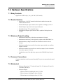
7.0 Hardware Specifications .................................................................................................................. 49
7.1 Relay Contacts ................................................................................................................. 49
7.2 Reader Interface ............................................................................................................... 49
7.3 Maximum Output Loading .............................................................................................. 49
7.4 Common Connections...................................................................................................... 49
7.5 Mechanical....................................................................................................................... 49
7.6 Environment..................................................................................................................... 50
7.7 Communications and Wiring ........................................................................................... 50
7.8 Reader Wiring.................................................................................................................. 51
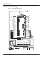
7.9 NX4L1 Panel Wiring Diagram ........................................................................................ 52
8.0 Maintenance ....................................................................................................................................... 53
9.0 Troubleshooting ................................................................................................................................ 55
10.0 Technical Support ........................................................................................................................... 56
10.1 Normal Support Hours................................................................................................... 56
10.2 Web ................................................................................................................................ 56
iv
www.honeywell.com
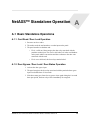
NetAXS™ Standalone Operation
A.1 Basic Standalone Operations.......................................................................................................... 57
A.1.1 Card Read / Door Lock Operation ............................................................................... 57
A.1.2 Door Egress / Door Lock / Door Status Operation ...................................................... 57
A.2 Standalone Settings.......................................................................................................................... 58
A.2.1 NetAXS™ Panel Hardware Settings ........................................................................... 58
A.2.2 Communication Settings.............................................................................................. 58
A.2.3 Emulation Settings ....................................................................................................... 58
A.2.4 Verifying Communications.......................................................................................... 58
A.3 Standalone Commands .................................................................................................................... 59
A.3.1 T (Time) Command ..................................................................................................... 59
A.3.2 D (Date) Command...................................................................................................... 60
A.3.3 L (Time Zone) Command ............................................................................................ 61
A.3.4 C (Card Add) Command .............................................................................................. 62
A.3.5 C (Card Delete) Command .......................................................................................... 62
A.3.6 W (Input) Command .................................................................................................... 63
A.3.7 P (Interlock) Command................................................................................................ 63
A.3.8 Flow Control Disable/Enable Command ..................................................................... 64
A.4 NetAXS™ Panel Defaults .............................................................................................................. 65
A.4.1 Reader Ports ................................................................................................................. 65
A.4.2 Reader LED Outputs ................................................................................................... 65
A.4.3 Reader Tamper Inputs.................................................................................................. 66
A.4.4 Door Egress Inputs....................................................................................................... 66
A.4.5 Door Status Inputs........................................................................................................ 67
A.4.6 ACFAIL and Panel Tamper Inputs .............................................................................. 67
A.4.7 Additional Generic Outputs ......................................................................................... 68
NetAXS Access Control Unit NX4L1 Installation Guide, Document 7-901099, Revision A
v
vi
www.honeywell.com
LIST OF FIGURES
Figure 1: NX4L1 Panel Components ......................................................................................... 6
Figure 2: Tying the Field Wiring in the NX4L1 Cabinet ......................................................... 11
Figure 3: NetAXS™ Panel Cabinet, Back View ...................................................................... 12
Figure 4: NetAXS™ Panel Cabinet, Top View ....................................................................... 13
Figure 5: NetAXS™ Panel Cabinet, Bottom View .................................................................. 13
Figure 6: NetAXS™ Panel Cabinet, Left View ....................................................................... 14
Figure 7: NetAXS™ Panel Cabinet, Right View ..................................................................... 15
Figure 8: Typical Supervised Input Wiring Diagram ............................................................... 18
Figure 9: Power Distribution Board Field Wiring .................................................................... 20
Figure 10: RJ-45 Serial Port ..................................................................................................... 21
Figure 11: RS-232 Configuration ............................................................................................. 22
Figure 12: RS-485 Configuration via N-485-PCI-2 or PCI-3 .................................................. 23
Figure 13: RS-485 Configuration via NetAXS™ Gateway ..................................................... 23
Figure 14: Ethernet TCP/IP Configuration .............................................................................. 24
Figure 15: Ethernet MAC Address Location ........................................................................... 25
Figure 16: DIP Switch and Jumper Location ........................................................................... 26
Figure 17: Default Downstream I/O Configuration with Wiring ............................................. 30
Figure 18: RS-485 Connection via PCI-2 ................................................................................ 31
Figure 19: RS-485 Connection via NetAXS™ ........................................................................ 32
Figure 20: RS-485 Connection via NetAXS™ with Multidrop Panels at Both Ends .............. 33
Figure 21: RS-485 Connection via PCI-2 with Multidrop Panels at Both Ends ...................... 34
Figure 22: RS-232 Connection ................................................................................................. 35
Figure 23: Ethernet Connection ............................................................................................... 36
Figure 24: LANSRLU1 Connection ......................................................................................... 37
Figure 25: RS-485 Short Haul Modem Connection via PCI-2 ................................................ 38
Figure 26: RS-485 Short Haul Modem Connection via NetAXS™ ........................................ 39
Figure 27: RS-232 Short Haul Modem Connection ................................................................. 40
Figure 28: M-56K Dial-up Modem, RS-485 Connection via Hub ........................................... 41
Figure 29: M-56K Dial-up Modem, RS-485 Connection via NetAXS™ ................................ 42
Figure 30: Fiber Converter to RS-485 Connection via PCI-2 .................................................. 43
Figure 31: Fiber Converter to RS-485 Connection via NetAXS™ .......................................... 44
Figure 32: N-485-PCI-2/NetAXS™ Access Controller Panel Connection Detail ................... 45
Figure 33: NetAXS™/NetAXS™ Access Controller Panel Connection Detail ...................... 46
Figure 34: System, Relay and Power LEDs ............................................................................. 47
Figure 35: NetAXS Panel Wiring Diagram ............................................................................. 52
NetAXS Access Control Unit NX4L1 Installation Guide, Document 7-901099, Revision A
vii
viii
www.honeywell.com
LIST OF TABLES
Table 1 Cabinet Electrical Entries ............................................................................................. 16
Table 2 Reader Wiring .............................................................................................................. 16
Table 3 Default Supervised Input Assignments ........................................................................ 17
Table 5 DIP Switch Settings ..................................................................................................... 27
Table 6 MIRO 32/0 DIP Switch and Jumper Settings .............................................................. 28
Table 7 LED Status ................................................................................................................... 48
Table 8 Communications and Wiring ....................................................................................... 50
Table 9 Reader Wiring .............................................................................................................. 51
Table 10 Troubleshooting Problems and Solutions .................................................................. 55
NetAXS Access Control Unit NX4L1 Installation Guide, Document 7-901099, Revision A
ix
x
www.honeywell.com
NetAXS™ NX4L1 Installation
1.0 Notices
1.1 Warnings and Cautions
Warning: Fire
Safety and Liability Notice: Never connect card readers to any critical
entry, exit door, barrier, elevator or gate without providing an alternative exit in
accordance with all fire and life safety codes pertinent to the installation. These
fire and safety codes vary from city to city and you must get approval from
local fire officials whenever using an electronic product to control a door or
other barrier. Use of egress buttons, for example, may be illegal in some cities.
In most applications, single action exit without prior knowledge of what to do
is a life safety requirement. Always make certain that any required approvals
are obtained in writing. Verbal approvals are not valid.
Warning: Honeywell never recommends using WIN-PAK or related products for use as
a primary warning or monitoring system. Primary warning or monitoring
systems should always meet local fire and safety code requirements. The
installer must also test the system on a regular basis by instructing the end user
in appropriate daily testing procedures. Failure to test a system regularly could
make installer liable for damages to the end user if a problem occurs.
Warning: Earth
ground all enclosures for proper installation.
Warning: Use
suppressors on all door locks. Use S-4 suppressors for installation.
Honeywell Access Systems (HAS) recommends only DC locks.
Warning: Personal
injury or death could occur, and the equipment could be damaged
beyond repair, if this precaution is not observed!
• Before installation, turn off the external circuit breaker which supplies power
to the system, including door locks.
• Before connecting the device to the power supply, verify that the output
voltage is within specifications of the power supply.
• Do not apply power to the system until after the installation has been
completed.
Caution: If
any damage to the shipment is noticed, a claim must be filed with the
commercial carrier responsible.
Caution: Electro-static
discharge (ESD) can damage CMOS integrated circuits and
modules. To prevent damage always follow these procedures:
NetAXS Access Control Unit NX4L1 Installation Guide, Document 7-901099, Revision A
1
NetAXS™ NX4L1 Installation
Notices
• Use static shield packaging and containers to transport all electronic
components, including completed reader assemblies.
• Handle all ESD sensitive components at an approved static controlled
workstation. These workstations consist of a desk mat, floor mat and an ESD
wrist strap. Workstations are available from various vendors.
1.2 Product Liability, Mutual Indemnification
In the event that a Customer receives a claim that a Product or any component thereof
has caused personal injury or damage to property of others, the Customer shall
immediately notify Honeywell in writing of all such claims. Honeywell shall defend
or settle such claims and shall indemnify and hold the Customer harmless for any
costs or damages including reasonable attorneys’ fees which the Customer may be
required to pay as a result of the defective Product or the negligence of Honeywell, its
agents or its employees.
The Customer shall hold harmless and indemnify Honeywell from and against all
claims, demands, losses and liability arising out of damage to property or injury to
persons occasioned by or in connection with the acts or omissions of the Customer
and its agents and employees, and from and against all claims, demands, losses and
liability for costs of fees, including reasonable attorneys’ fees in connection therewith.
1.3 Limited Warranty
All Products sold or licensed by Honeywell Access Systems (HAS) include a
warranty registration card which must be completed and returned to HAS by or on
behalf of the end user in order for Honeywell to provide warranty service, repair,
credit or exchange. All warranty work shall be handled through the Customer which
shall notify Honeywell and apply for a Return Merchandise Authorization (RMA)
number prior to returning any Product for service, repair, credit or exchange.
Honeywell warrants that its Products shall be free from defects in materials and
workmanship for a period of one year from date of shipment of the Product to the
Customer. The warranty on Terminals, Printers, Communications Products and
Upgrade kits is 90 days from date of shipment. Satisfaction of this warranty shall be
limited to repair or replacement of Products which are defective or defective under
normal use.
Honeywell’s warranty shall not extend to any Product which, upon examination, is
determined to be defective as a result of misuse, improper storage, incorrect
installation, operation or maintenance, alteration, modification, accident or unusual
deterioration of the Product due to physical environments in excess of the limits set
forth in Product manuals.
2
www.honeywell.com
NetAXS™ NX4L1 Installation
Notices
THERE ARE NO WARRANTIES THAT EXTEND BEYOND THIS PROVISION. THIS
WARRANTY IS IN LIEU OF ALL OTHER WARRANTIES WHETHER EXPRESS, IMPLIED OR
STATUTORY, INCLUDING IMPLIED WARRANTIES OF MERCHANTABILITY OR FITNESS
FOR ANY PARTICULAR PURPOSE. NO REPRESENTATION OR WARRANTY OF THE
DISTRIBUTOR SHALL EXTEND THE LIABILITY OR RESPONSIBILITY OF THE
MANUFACTURER BEYOND THE TERMS OF THIS PROVISION. IN NO EVENT SHALL
HONEYWELL BE LIABLE FOR ANY RE-PROCUREMENT COSTS, LOSS OF PROFITS, LOSS
OF USE, INCIDENTAL, CONSEQUENTIAL OR SPECIAL DAMAGES TO ANY PERSON
RESULTING FROM THE USE OF HONEYWELL PRODUCTS.
1.4 Federal Communications Commission
This equipment has been tested and found to comply with the limits for a Class B digital device,
pursuant to part 15 of the FCC Rules. These limits are designed to provide reasonable protection
against harmful interference in a residential installation. This equipment generates, uses, and can
radiate radio frequency energy, and if not installed and used in accordance with the instructions, may
cause harmful interference to radio communications. However, there is no guarantee that interference
will not occur in a particular installation. If this equipment does cause harmful interference to radio or
television reception, which can be determined by turning the equipment off and on, the user is
encouraged to try to correct the interference by one or more of the following measures:
• Re-orient or re-locate the receiving antenna.
• Increase the separation between the equipment and receiver.
• Connect the equipment into an outlet on a circuit different from that to which the receiver is
connected.
• Consult the dealer or an experienced radio/TV technician for help.
The user shall not make any changes or modifications to the equipment unless authorized by the
Installation Instructions or User’s Manual. Unauthorized changes or modifications could void the
user’s authority to operate the equipment.
For panels using the Ethernet connection, the cable clamp (HAS part number 3-000342) must be used
for the panel to pass the FCC Part 15 Class B requirements. See “Installation“ on page 9 for clamp
installation instructions.
1.5 Industry Canada
This Class B digital apparatus meets all requirements of the Canadian Interference-Causing Equipment
Regulations.
Cet appareil numérique de la classe B respecte toutes les exigences du Réglement sur le matériel
brouilleur du Canada.
NetAXS Access Control Unit NX4L1 Installation Guide, Document 7-901099, Revision A
3
NetAXS™ NX4L1 Installation
Notices
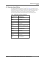
1.6 Underwriters Laboratories Incorporated
The NetAXS™ panel was reviewed by Underwriters Laboratories Incorporated for
Access Control System Units - Category ALVY, UL294 standard. The NetAXS™
panel was reviewed as a stand alone system. The input points only monitor the door
position. The NetAXS™ panel is not intended as a Proprietary Alarm Unit - Category
APOU, UL1076 standard.
The NetAXS™ panel was reviewed using the following Honeywell readers:
OmniAssure (TM) OT30, OmniClass (TM) OM40 and OM55, and OmniProx (TM)
OP30 and OP40.
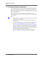
Notes:
• All field wiring, except for the AC power input and the battery backup/charger
wiring, is Class 2 power-limited.
• Communication between panels other than the NetAXS panel has not been
evaluated by UL.
• Underwriters Laboratories (UL) has reviewed only the configurations shown
in Section 5.1, "RS-485 Connection via PCI-2" on page 31, Section 5.2,
"RS-485 Connection via NetAXS™" on page 32, and Section 5.4, "RS-232
Connection" on page 35 of this guide. Because UL has reviewed the NetAXS
panel only as a standalone system, the computer terminal, NetAXS gateway
panel, and N-485_PCI-2 adapter appear in these sections only to illustrate the
installation and programming of the NetAXS panel.
• UL has not evaluated the compatibility of downstream I/O devices (see
Section 4.10, "Downstream I/O" on page 28) with the NetAXS panel.
4
www.honeywell.com
NetAXS™ NX4L1 Installation
Introduction
2.0 Introduction
2.1 Access Control Overview
An access control system protects and preserves an enterprise’s resources by
providing authentication, authorization, and administration services. Authentication is
a process that verifies a user’s identity. If the user is verified, the system then either
grants or denies access to specific areas and resources. Administration includes the
creation and modification of user accounts and access privileges.
An access control system consists of hardware and software, usually configured in a
network environment over a standard network protocol. Access control units, readers,
door strikes, and video and other devices, for example, are configured to control and
monitor the access to a company site.
2.2 NetAXS™ Access Overview
A NetAXS™ access control system consists of a host system and NetAXS™ access
control units that meet existing N-1000-III/IV specifications and that communicate
with each other and with a variety of input and output devices over the RS-232 and
RS-485 network protocols. See “System Configuration“ on page 31 to view
illustrations of the supported NetAXS™ system configurations. A NetAXS™ access
control system is configured and maintained via either the host system or a web server
using RS-232, RS-485, or Ethernet network protocols.
This document describes how to install and configure the NX4L1 access control unit.
NetAXS Access Control Unit NX4L1 Installation Guide, Document 7-901099, Revision A
5
NetAXS™ NX4L1 Installation
Panel Components and Descriptions
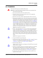
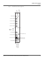
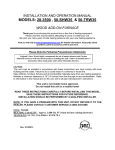
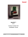
3.0 Panel Components and Descriptions
The NX4L1 access control unit consists of a NetAXS panel control board, a power
distribution module, a power supply, and batteries. The components are enclosed in a
pre-wired cabinet. The 24V power supply provides power for the panel control board,
which is a four-reader panel providing access control for up to four doors. The control
board is overridden in cases of fire emergency by the HPACM8 Power Distribution
Board.
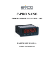
The following figure shows the NX4L1 panel components.
Figure 1:
NX4L1 Panel Components
Enclosure Tamper Switch
NetAXS Access
Control Panel
24VDC
Power
Supply
(cover not
shown)
Cables
with heat
shrink
barriers
Cables
with heat shrink
barriers
3.5A
250V
Fuse
Mounting
Screws
Mounting
Screw
HPACM8
Power Distribution Board
Power
Inlet
Terminal
Block
3 A, 250V
Bussman type
GMA fuse
6
www.honeywell.com
Pb
Pb
NetAXS™ NX4L1 Installation
Panel Components and Descriptions
Maintain at least a .25-inch distance between the non-power limited wiring (115
VAC/60 Hz input wiring, power line filter wiring, 24 VDC wiring, battery
backup/charger wiring, and battery-to-battery wiring) and all other wiring, which is
power-limited Class 2 wiring.
Note:
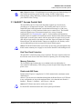
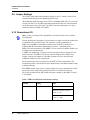
3.1 NetAXS™ Access Control Unit
The NetAXS™ panel is a four-reader board that controls up to four doors by
providing up to 14 inputs and 8 outputs. The NetAXS panel may be used as a
stand-alone panel with independent card and transaction storage or, with a host
software upgrade, as a fully monitored online access control device. The NetAXS
panel also supports up to 30 downstream panels in a variety of network
configurations. See Communications, page 21, for descriptions and illustrations.
Fourteen inputs are capable of four state supervision: Normal, Alarm, Short and Open.
Eight inputs are used as door control with one input used for request to exit on each
door and one input used for door status on each door. Supervised inputs for Tamper,
External Power Fail and four Reader Tampers are supplied as well, and they can be
used as additional inputs when not required for their default purpose.
Caution: The NetAXS board must not be used to power locks. Only through the relay
board can the common power supply be used for the NetAXS™ and locking devices.
Real-Time Clock Protection
The panel RTC is backed up using a super capacitor. The super capacitor will power
the real-time clock for one week in the absence of primary power or backup battery.
Memory Protection
The NetAXS™ panel continuously saves database and event information in
non-volatile FLASH memory. This activity prevents the panel from losing data when
power is lost.
Reader and AUX Power
Reader and AUX power is supplied at 12.4 VDC nominal with a maximum current
distribution of
600 mA. The current can be distributed throughout the Reader Power or AUX Power
in any configuration as long as the maximum draw is less than 600 mA: Reader 1 +
Reader 2 + Reader 3 + Reader 4 + AUX Power < 600 mA.
Caution: AUX
Power must not be used to power locks.
For NetAXS™ maximum current draw refer to panel specifications.
NetAXS Access Control Unit NX4L1 Installation Guide, Document 7-901099, Revision A
7
NetAXS™ NX4L1 Installation
Panel Components and Descriptions
3.2 Power Supply
The NX4L1 uses an internal 115 VAC to 24 VDC regulated power supply (Altronix
Model AL600ULXB). The supply uses 115 VAC, 60 Hz, 2 Amp input, and provides
24 VDC at 6 Amps for the system power. The supply also charges and monitors the
condition of the batteries. Wire the unswitched electrical power to the supply per the
National Electrical Code as well as any local electrical codes, including the safety
ground wire.
An input power indicator is supplied, and it is illuminated when input voltage is
present. If the indicator is off, the input voltage is off, or too low to operate the system.
Caution: De-energize
the unit before servicing it. For continued protection against the
risk of electric shock and fire hazard, replace the input fuse with the rating of 3.5A,
250V.
3.3 Batteries
For the NX4L1, two CASIL CA1270, 12 VDC, 7 AHr sealed lead-acud batteries
(Honeywell order number 3-000066) wired in series must be used to have backup
battery capabilitiy. The batteries will provide standby backup power, depending upon
system configuration and activity. The batteries are wired in series (positive on one
battery to negative on the other) and connected to the BATT + and BATT - terminals
on the 24 VDC power supply in the NetAXS™ enclosure. When AC is lost, the power
supply automatically switches to the backup batteries for continuous 24 VDC power.
The power supply has deep discharge protection, and it can provide a Low Battery
signal to the panel if it is connected to a supervised input on the NetAXS™ panel.
Refer to the system wiring diagram for details. Replace the batteries every 2 to 2.5
years, or more often if the system has a high rate of backup use.
3.4 Enclosure
The enclosure is 450 mm (17.7 inches) wide, 607 mm (23.9 inches) high, 90 mm (3.54
inches) deep. The enclosure is shipped pre-wired.
3.5 Suppressors
Two suppressors (HAS number S-4) are required for each door lock. One suppressor
is installed on the panel control board, and the second must be installed at the door
lock.
8
www.honeywell.com
NetAXS™ NX4L1 Installation
Installation
4.0 Installation
Perform the following steps to install the NX4L1 panel:
Warning: Use
a static strap whenever touching the panel to ensure protection from
Electrostatic Discharge (ESD).
1. Review the panel layout, cable runs, and power needs.
2. Mount the enclosure at the proper location on the wall. Use appropriate
anchors for the mounting material.
3. Run all I/O wires to the enclosure, and properly mark each wire for its use.
4. Run appropriate length three-wire cable to the enclosure power inlet terminal
block. Ensure that the ground wire is properly grounded to earth. Note that an
Optional Power Connection kit (HAS part number 100-00049) is available for
the NX4L1 panel. To install the Power Connection option, see “Installing the
Optional AC Inlet“ on page 10 for instructions. The power inlet terminal block
can accommodate wire sizes up to 12 AWG. Wiring to a 20-amp branch circuit
requires 12 AWG insulated copper wire. Wiring to a 15-amp branch circuit
requires 14 AWG insulated copper wire. Connect the line, neutral, and earth
ground wires to the appropriate terminal on the power inlet terminal block.
Caution: Do
not apply power at this time.
5. Remove each terminal plug one at a time to wire the properly labeled cables.
See the wiring diagram (Figure 35 on page 52). Leave enough shield drain
length to secure to the grounding stud. Also, maintain a distance of at least .25
inches between the non-power limited wiring (115 VAC/60 Hz input wiring,
power line filter wiring, 24 VDC wiring, battery backup/charger wiring, and
battery-to-battery wiring) and all other wiring, which is power-limited Class 2
wiring.
Caution: Do
not apply power at this time.
6. Connect the shield to the grounding studs.
7. Set DIP switch settings for the panel address (see Table 5 on page 27), and set
J36 and J37 for communication termination and biasing (see “System
Configuration“ on page 31 and “Jumper Settings“ on page 28).
8. Check all wiring at this time.
Caution: Improper wiring can cause damage to the NetAXS™ at power up and
result in a loss of warranty.
9. Apply power to the panel. The power-up sequence may take up to two minutes,
after which the RUN LED blinks green. The RUN LED is located near
Terminal Block (TB) 8. After the power-up sequence, check the LEDs to be
sure the panel has powered up properly (see “LED Operation“ on page 47).
10.Configure the panel by following the instructions in the NetAXS™ Access
Control Unit User’s Guide.
NetAXS Access Control Unit NX4L1 Installation Guide, Document 7-901099, Revision A
9
NetAXS™ NX4L1 Installation
Installation
11.If you are using a battery backup function, place the two 7 A-Hr batteries in the
enclosure with the battery terminals of each battery close to each other.
12.Attach the 4-inch Battery-to-Battery cable from the positive (red) terminal of
one battery to the negative (black) terminal of the other battery. DO NOT
CONNECT THE CABLE BETWEEN THE TERMINALS OF THE SAME
BATTERY.
13.Attach the positive (red) Power Supply-to-Battery cable to the remaining
positive (red) battery terminal.
14.Attach the negative (black) Power Supply-to-Battery cable to the remaining
negative (black) battery terminal.
15.For panels using the Ethernet connection, the cable clamp (HAS part number
3-000342) must be used for the panel to pass the FCC Part 15 Class B
requirements. Snap the clamp around any portion of the Ethernet cable that is
inside of the enclosure.
4.1 Installing the Optional AC Inlet
Perform these steps to install the optional AC inlet (HAS part number 100-00049):
1. Remove the knockout piece at the lower-left side of the enclosure.
2. Feed the AC inlet assembly wires through the opening from the outside.
3. Push the receptacle straight in, until it snaps into place.
4. Connect each colored wire to its corresponding color on the terminal block.
5. Plug the AC inlet unit’s power cord into the three-prong receptacle.
6. Plug the other end of the cable into a standard non-switched 115 VAC outlet.
Use only a Yung Li YC-12 power cord (HAS part number 700-0109). UL has
evaluated the use of this power cord with the optional AC inlet for the NX4L1. You
can purchase this power cord from Honeywell.
Note:
10
www.honeywell.com
NetAXS™ NX4L1 Installation
Installation
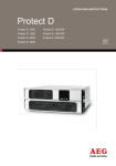
4.2 Tying the Field Wiring in the NX4L1 Cabinet
Use the following figure as a guide to secure the field wiring in the NX4L1 cabinet.
Figure 2: Tying the Field Wiring in the NX4L1 Cabinet
.
Pb
Pb
Location of wire tie points
and suggested routing of
Class 2 power-limited field
wiring to maintain a
minimum of 0.25 inch
spacing from non-powerlimited wiring
NetAXS Access Control Unit NX4L1 Installation Guide, Document 7-901099, Revision A
Wiring shown as ||||||||||||||||||||||||||||
represent shrink wrap barrier
protection (0.028 inch thickness
minimum) where spacing between
non-power-limited and power-limited
wiring is less than 0.25 inches.
11
NetAXS™ NX4L1 Installation
Installation
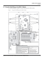
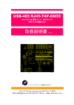
4.3 Cabinet Mounting
The following five figures show the back, top, bottom, right, and left views of the NetAXS™ panel
cabinet. Each view includes the dimensions and knockout placement that you will need to mount the
cabinet. See Table 1 on page 16 for dimensions of the conduit entries into the cabinet.NetAXS™ Panel
Cabinet, Back View
Figure 3:
NetAXS™ Panel Cabinet, Back View
0
27/32" (21.8 mm)
2 9/16" (65 mm)
8 27/32" (225 mm)
15 5/32" (385 mm)
17 23/32" (450 mm)
16 27/32" (428.2 mm)
0
0
23/32" (18 mm)
15/32" (11.51 mm)
15/32" (11.51 mm)
3 13/32"
(86.51 mm)
9 3/8"
(238.50 mm)
22 29/32"
(581.6 mm)
23 1/8" (587 mm)
23 29/32" (607 mm)
www.honeywell.com
27/32" (21.8 mm)
16 5/32" (410 mm)
16 17/32" (420 mm)
16 27/32" (428.2 mm)
12
NetAXS™ NX4L1 Installation
Installation
Figure 4:
NetAXS™ Panel Cabinet, Top View
1 5/8" (41 mm)
31/32" (25 mm)
0
0
1 31/32" (50 mm)
4 1/8" (105 mm)
Back
13 19/32" (345 mm)
15 3/4" (400 mm)
Figure 5: NetAXS™ Panel Cabinet, Bottom View
0
1 31/32" (50 mm)
4 1/8" (105 mm)
5 23/32" (145 mm)
Back
8 27/32" (225 mm)
12" (305 mm)
13 19/32" (345 mm)
15 3/4"" (400mm)
0
31/32" (25 mm)
1 5/8" (41 mm)
NetAXS Access Control Unit NX4L1 Installation Guide, Document 7-901099, Revision A
13
NetAXS™ NX4L1 Installation
Installation
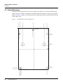
Figure 6:
NetAXS™ Panel Cabinet, Left View
0
1 5/8"
(41 mm)
0
2 9/16" (65 mm)
2 5/32" (55 mm)
4 17/32" (115 mm)
4 23/32" (120 mm)
6 11/16" (170 mm)
8 21/32" (220 mm)
10 10/16" (270 mm)
Back
16 30/32" (430 mm)
18 29/32" (480 mm)
22 3/8" (568.5 mm)
31/32"
(25 mm)
14
www.honeywell.com
NetAXS™ NX4L1 Installation
Installation
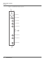
Figure 7:
NetAXS™ Panel Cabinet, Right View
3 11/16"
(93.5 mm)
1 5/8"
(41 mm)
0
0
0
2 9/16" (65 mm)
4 23/32" (120 mm)
6 11/16" (170 mm)
8 21/32" (220 mm)
10 10/16" (270 mm)
Back
15 3/4" (400 mm)
17 3/16" (436.87" mm)
17 23/32" (450 mm)
13/16" (21 mm)
20 1/8" (511.5 mm)
20 11/32" (517 mm)
20 15/16" (532 mm)
1 3/16" (30.5 mm)
1 19/32" (40.1 mm)
22 3/8" (568mm)
2 19/32" (65 mm)
1 31/32" (50 mm)
31/32" (25 mm)
0
NetAXS Access Control Unit NX4L1 Installation Guide, Document 7-901099, Revision A
15
NetAXS™ NX4L1 Installation
Installation
Table 1 lists the dimensions of the cabinet’s conduit entries.
Table 1 Cabinet Electrical Entries
ENCLOSURE
CONDUIT
1/2” (12.7 mm)
CONDUIT
3/4” (19.0 mm)
CONDUIT 1”
(25.4 mm)
CONDUIT 2”
(50.8 mm)
Top
5
5
N/A
2
Bottom
2
2
N/A
2
Right Side
8
8
N/A
N/A
Left Side
6
6
N/A
N/A
Back
N/A
N/A
2
N/A
4.4 Reader Wiring
Each reader port supports a single 12-volt reader with Wiegand output format. Power
to the readers is shared with the AUX Power ports TB3 and TB14. The maximum
power draw is 600 mA for readers and AUX Power combined.
To fully utilize each reader port, a shielded 7-conductor cable (18-22 AWG) is
required. If the optional reader buzzer feature is not needed, you can use the standard
six-conductor cable (HAS part number NC1861-BL). The cable shield should be
grounded at the panel only. Grounding at both ends can cause ground loops which can
be disruptive. The maximum recommended length of wiring is 500 feet per reader.
Table 2 Reader Wiring
16
Terminal
Wire Color
Wiegand Reader
TB5-1, 6-1, 11-1, 12-1
Brown
LED Control
TB5-2 6-2, 11-2, 12-2
Green
Wiegand Data 0
or Data
TB5-3, 6-3, 11-3, 12-3
White
Wiegand Data 1
or Clock
TB5-4, 6-4, 11-4, 12-4
Black
Common
TB5-5, 6-5, 11-5, 12-5
Red
12VDC Power
TB5-6, 6-6, 11-6, 12-6
Variable
Tamper
TB5-7, 6-7, 11-7, 12-7
Variable
Buzzer
www.honeywell.com
NetAXS™ NX4L1 Installation
Installation
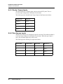
4.5 Supervised Input Wiring
The supervised inputs are located on TB4 and TB13 (Figure 8 on page 18). Input 1
through Input 8 may be configured for normally open or normally closed contacts as
supervised or non-supervised. Inputs 13 and 14 are on TB8. All eight inputs have
default functions, but they can be configured for general purpose inputs.
The following table identifies the default function for each terminal position.
Table 3 Default Supervised Input Assignments
Terminal Position
Default Function
TB4-1
Door 1 REX (Egress)
TB4-3
Door 1 Status
TB4-4
Door 2 REX (Egress)
TB4-6
Door 2 Status
TB8-1
External Power Supply AC FAIL
TB8-3
Panel Tamper
TB13-1
Door 3 REX (Egress)
TB13-3
Door 3 Status
TB13-4
Door 4 REX (Egress)
TB13-6
Door 4 Status
TB 5-6, 6-6, 11-6,
12-6
Optional supervised input if not used
for a reader tamper
NetAXS Access Control Unit NX4L1 Installation Guide, Document 7-901099, Revision A
17
NetAXS™ NX4L1 Installation
Installation
The following figure shows the typical wiring for a supervised input.
Figure 8: Typical Supervised Input Wiring Diagram
NO
2.2K
NC
2.2K
2.2K
2.2K
TB 4
1
2
3
4
5
6
DOOR 1 EGRESS
COMMON
DOOR 1 STATUS
DOOR 2 EGRESS
COMMON
DOOR 2 STATUS
The figure above shows standard 2,200 ohm resistors. The NetAXS™ panel accepts
1,000, 2,200, 4,700, or 10,000 ohm values. Note that both resistors must have the
same value. See the NetAXS™ Access Control Unit User’s Guide for instructions on
selecting resistor options.
In addition, the Tamper and External Power Fail, as well as the Reader and Panel
tampers can be supervised and capable of being used as additional inputs if the default
functionality is not needed. They also share a single common.
The wire used for the inputs should be shielded and cannot exceed 30 ohms over the
entire length of the cable. Remember that the distance from the panel to the door must
be doubled to determine the total resistance.
Caution: The
cable shield should be grounded only at the panel earth ground.
Grounding at both ends can cause ground loops which can be disruptive.
Caution: The system has not been verified for compliance with UL1076 Burglar
Alarm units and systems.
4.6 NX4L1 Control Output Wiring
The NX4L1 provides a Power Distribution Output circuit board that is pre-wired to
the eight relays on the control panel. Each panel relay controls the correspondingly
numbered Power Distribution Output relay.
Relay 1 is defaulted for control of the Door 1 lock, Relay 2 is defaulted for the control
of the Door 2 lock, Relay 3 is defaulted for the control of the Door 3 lock, and Relay 4
is defaulted for the control of the Door 4 lock. Relays 5-8 are used as auxiliary relays.
Refer to the NetAXS Access Control Unit User’s Guide for details on controlling the
relay operations. The NX4L1 is wired to enable the internal nominal 24 VDC power
supply to be used to power the access control door strikes/locks or other auxiliary
loads. The voltage range of the relay outputs is 23.5 VDC to 25 VDC. If the
application requires a separate supply, refer to the Power Distribution Output board
installation manual for details.
18
www.honeywell.com
NetAXS™ NX4L1 Installation
Installation
Each Power Distribution Output relay has a 2 Amp Positive Temperature Coefficient
(PTC)-protected output and a yellow indicator LED. The yellow LED illuminates if
the PTC is active. Each relay also has a red indicator LED, which indicates the relay
state. If the relay is active, the LED is illuminated.
For field wiring, attach the negative terminal of the load to the NEG output terminal of
the Power Distribution Output relay. Attach the positive load terminal to either the
Normally Open or Normally Closed terminal of the Power Distribution Output relay.
Refer to Figure 9 on page 20 for a wiring example.
Caution: The cable used must be sized for the current load and should be shielded. The
cable shield should be grounded at the panel only. Grounding at both ends can cause
ground loops which can be disruptive. Do not bundle these wires with
communication, reader, or supervised input wiring.
To minimize premature contract failure and increase system reliability, a contact
protection circuit (HAS part number S-4) is highly recommended. Locate the
protection circuit as close as possible to the load.
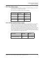
The Power Distribution Output board can be connected to an external Fire Alarm
Control Panel (FACP). When the FACP input signal is active, it will turn off the
selected relays on the Power Distribution Output board. An eight-position DIP switch
is used to select which Power Distribution Output relays are affected by the FACP
input. To make an output respond to the FACP input, move the associated DIP switch
to the OFF position. To have the relay ignore the state of the FACP input, move the
DIP switch to the ON position.
The Power Distribution Output board has a green LED that indicates the status of the
external FACP input. The LED will turn on when the input is active and turn off when
inactive.
Table 4: NetAXS Relay and Power Distribution Board DIP Switch Associations
Default
Function
NetAXS Board
Relay
Power Distribution
Output Board Relay
Power Distribution
Output Board DIP
Switch
Door 1
1
1
1
Door 2
2
2
2
Door 3
3
3
3
Door 4
4
4
4
Auxiliary
5
5
5
Auxiliary
6
6
6
Auxiliary
7
7
7
Auxiliary
8
8
8
NetAXS Access Control Unit NX4L1 Installation Guide, Document 7-901099, Revision A
19
NetAXS™ NX4L1 Installation
Installation
The Power Distribution Output board has two dry contact outputs that can be used to monitor the
general condition of the system. The TRBL relay output is de-energized if the +24 VDC is off or if a
PTC is active. The FACP relay output will de-energize if the external FACP input is active. Either one
of these outputs can be optionally wired into the supervised inputs on the NetAXS panel and
configured as two-state inputs.
The following figure shows the power distribution board field wiring. Power Distribution Board Field
Wiring
Figure 9:
20
www.honeywell.com
Power Distribution Board Field Wiring
NetAXS™ NX4L1 Installation
Installation
4.7 Communications
Caution: Do
not route communication wires with power or locking devices.
Note: Because UL has reviewed the NetAXS panel only as a standalone system, the
computer terminal, NetAXS gateway panel, and N-485_PCI-2 adapter appear in this
section’s figures only to illustrate the installation and programming of the NetAXS
panel.
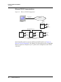
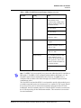
RS-232 Communications
The NetAXS™ panel communicates with a PC through a 50-foot RS-232 cable (HAS
part number CBL50). Connect the RJ45 end of the cable to the jack on the NetAXS™
panel.
The cable is used to provide communication to a single panel. A second cable can be
used with another NetAXS™ control panel connected to a second COM
(communication) port, which would enable eight readers to be used, see Figure 11,
RS-232 Configuration.
Figure 10 illustrates the connections for an RS-232, DB9 (9 pin) connector to the
panel’s RJ-45 serial port. Replacement cables can be obtained by contacting your
Honeywell Access System Representative.
Figure 10: RJ-45 Serial Port
NetAXS Access Control Unit NX4L1 Installation Guide, Document 7-901099, Revision A
21
NetAXS™ NX4L1 Installation
Installation
Figure 11: RS-232 Configuration
Reader 1
COM1
NetAXS
Panel
Reader 4
CBL50
Terminal
Reader 1
COM2
NetAXS
Panel
Reader 4
One NetAXS panel per COM port. Two COM ports possible.
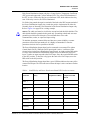
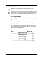
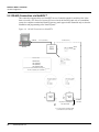
RS-485 Communications
The NetAXS™ panel can reside on an existing RS-485 drop line hosted by either a
NetAXS™ panel configured as a Gateway, or N-485-PCI-2, PCI-3, or N-485-HUB-2
(see Figure 12, Figure 13, and Figure 24). The interface allows the wiring of a
Multidrop communication network of up to 4,000 feet (1200 m) in length. Only one
host converter device per dropline is supported.
Note: On a Multidrop Line, the Gateway panel and the PCI unit can have either
end-point or interior positions. See Figure 20 on page 33 and Figure 21 on page 34.
DIP switch position 6 on the NetAXS™ panel selects whether the panel is a Gateway
or Multidrop panel. The switch in the OFF position configures the panel as a
Multidrop panel; ON configures a Gateway. The panel must be power cycled for a
new switch setting to be recognized. DIP switch positions 1-5 are used to select the
panel’s address on the network. Refer to Table 5 for DIP switch setting information.
Connectors J36 and J37 are provided for supplying biasing and end-of-line
termination for the RS-485 network. The board ships with all jumpers open. For a
Multidrop RS-485 Line, you must close both J36 and J37 (terminated and biased) at
the two end-point panels. At all other panels, leave J36 and J37 open. Both jumpers on
a given panel must set the same. Note that biasing and termination on both ends are
present. Use the jumpers on both ends of the RS-485 network.
If an RS-485 network has a NetAXS™ Gateway panel, no N1000-II, N1000-III,
or N1000-IV are allowed on the same network. If they are added to a network with a
NetAXS™ Gateway panel, they will not be able to communicate with the host
computer.
Note:
22
www.honeywell.com
NetAXS™ NX4L1 Installation
Installation
Figure 12:
RS-485 Configuration via N-485-PCI-2 or PCI-3
N-485-PCI-2/3
COM1
Terminal
RS-485 Multidrop Line
N1000 III
N1000 IV
Reader 1
Reader 2
Reader 1
Reader 1
NS2+
Panel
Reader 2
NetAXS
Panel
Reader 4
A combination of N1000 III, N1000 IV, NS2+ and NewAXS panels,
supporting a total of 31 panels per multi-drop line
Figure 13:
RS-485 Configuration via NetAXS™ Gateway
COM1
NetAXS
Gateway
Reader 1
Reader 4
Terminal
RS-485 Multidrop Line
Reader 1
NS2+
NetAXS
Reader 4
Reader 1
Reader 1
NetAXS
Reader 2
Reader 4
A combination of NetAXS and NS2+ panels, supporting a total of 31
panels per multi-drop line
NetAXS Access Control Unit NX4L1 Installation Guide, Document 7-901099, Revision A
23
NetAXS™ NX4L1 Installation
Installation
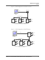
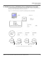
Ethernet TCP/IP Communications
Figure 14:
Ethernet TCP/IP Configuration
Network Interface
Card Inside PC
Ethernet
Up to 255 TCP/IP Connections per System
Ethernet
10/100
Terminal
NetAXS
Gateway
Reader 1
Reader 4
RS-485 Multidrop Line
Reader 1
Reader 4
Reader 1
Reader 1
NS2+
NetAXS
NetAXS
Reader 2
Reader 4
A combination of NetAXS and NS2+ panels, supporting a total of 31
panels per multi-drop line
Each NetAXS™ panel has a port for an Ethernet TCP/IP interface (see Figure 14,
Ethernet TCP/IP Configuration). The Ethernet TCP/IP interface provides 10/100 Mbit
Ethernet support for each panel. Up to 31 panels can be configured on each TCP/IP
connection.
24
www.honeywell.com
NetAXS™ NX4L1 Installation
Installation
Figure 15 shows the location of the panel’s unique MAC ID.
Figure 15: Ethernet MAC Address Location
Label with Ethernet MAC Address
NetAXS Access Control Unit NX4L1 Installation Guide, Document 7-901099, Revision A
25
NetAXS™ NX4L1 Installation
Installation
4.8 DIP Switch Settings
Figure 16 locates the NX4L1 DIP switch panel and the J36 and J37 jumpers.
Figure 16:
DIP Switch and Jumper Location
J37
J36
DIP
Switches
26
www.honeywell.com
NetAXS™ NX4L1 Installation
Installation
Use the following DIP switch configurations to set the panel address.
Table 5 DIP Switch Settings
S1
S2
S3
S4
S5
on
off
on
off
on
off
on
off
on
off
on
off
on
off
on
off
on
off
on
off
on
off
on
off
on
off
on
off
on
off
on
off
on
on
off
off
on
on
off
off
on
on
off
off
on
on
off
off
on
on
off
off
on
on
off
off
on
on
off
off
on
on
off
off
off
on
on
on
on
off
off
off
off
on
on
on
on
off
off
off
off
on
on
on
on
off
off
off
off
on
on
on
on
off
off
off
off
off
off
off
on
on
on
on
on
on
on
on
off
off
off
off
off
off
off
off
on
on
on
on
on
on
on
on
off
off
off
off
off
off
off
off
off
off
off
off
off
off
off
on
on
on
on
on
on
on
on
on
on
on
on
on
on
on
on
Note:
S6
Selection
off
on
Address 1 (default)
Address 2
Address 3
Address 4
Address 5
Address 6
Address 7
Address 8
Address 9
Address 10
Address 11
Address 12
Address 13
Address 14
Address 15
Address 16
Address 17
Address 18
Address 19
Address 20
Address 21
Address 22
Address 23
Address 24
Address 25
Address 26
Address 27
Address 28
Address 29
Address 30
Address 31
NetAXS™ Multidrop
NetAXS™ Gateway
Address 0 is not a valid setting.
NetAXS Access Control Unit NX4L1 Installation Guide, Document 7-901099, Revision A
27
NetAXS™ NX4L1 Installation
Installation
4.9 Jumper Settings
The NX4L1 panel control board includes jumpers 36 and 37, which set end-of-line
termination and biasing for the Multidrop RS-485 Line.
The board ships with all jumpers set to OFF. For a Multidrop RS-485 Line, you must
set both J36 and J37 to CLOSED (terminated and biased) at the two end-point panels.
At all other panels, leave J36 and J37 at OPEN. Note that both jumpers on a given
panel must either be OPEN or CLOSED.
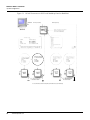
4.10 Downstream I/O
Note: UL has not evaluated the compatibility of downstream I/O devices with the
NetAXS panel.
In some applications, the number of system inputs or outputs exceeds the number that
is standard on the NetAXS™ panel. The solution is to add a combination of
MIRO-2/16 and MIRO-32/0 modules external to the NetAXS™ enclosure on a
dedicated RS-485 Downstream Input/Output (I/O) bus. A maximum of two
MIRO-32/0 and a maximum of four MIRO-2/16 for a total of six MIRO modules can
be added to the downstream bus.
A MIRO-32/0 module has 32 supervised, four-state inputs that are limited to 2,200
ohms resistance. The MIRO-2/16 has two supervised inputs and 16 SPDT relay
outputs; each input is limited to 2,200 ohms resistance. Refer to the individual
installation manuals for I/O wiring details.
The downstream I/O bus is wired into the NetAXS™ TB10 terminal block. The
downstream bus has a fixed baud rate and communicates to the MIRO modules using
a polling technique.
Each MIRO module needs to have a unique address for proper communication. Each
one also has some configuration jumpers that need to be positioned correctly.
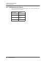
The following table lists the DIP switch and jumper settings for the MIRO 32/0 and
2/16 modules.
Table 6 MIRO 32/0 DIP Switch and Jumper Settings
Module
Setting
Value
MIRO 32/0
DIP switches
Address (switches 1-6) - 1 or 2
Baud rate (switches 7 and 8) - 7
= OFF, 8 = ON
OP Mode (switches 9 and 10) - 9
= OFF, 10 = OFF
28
www.honeywell.com
NetAXS™ NX4L1 Installation
Installation
Table 6 MIRO 32/0 DIP Switch and Jumper Settings (continued)
Module
Setting
Value
Jumper settings
JP1 - CLOSED (if the module is
the last module on the
downstream bus), OPEN (if the
module is not the last module on
the downstream bus)
JP2 - any setting
JP3 - any setting
JP4 - NORMAL
(Positions 1 and 2)
MIRO 2/16
DIP switches
Address (switches 1-6) - 3
through 6
Baud rate (switches 7 and 8) - 7
= OFF, 8 = ON
OP Mode (switches 9 and 10) - 9
= OFF, 10 = OFF
Jumper settings
JP1 - CLOSED, positions 2 and
3 (if the module is the last
module on the downstream bus);
OPEN, positions 1 and 2 (if the
module is not the last module on
the downstream bus)
JP2 - NORMAL, positions 1
and 2
If a MIRO 32/0 is not required in a system, start addressing the 2/16 modules at
DIP switch 3. If a MIRO 32/0 is configured with an address other than 1 or 2, the
NetAXS™ panel will not communicate with it. Likewise, if a MIRO 2/16 is
configured with an address other than 3 through 6, the NetAXS™ panel will not
communicate with it.
Note:
The NetAXS™ board and the NX4L1 is not intended to provide either module power
or module output load power for downstream I/O. A separate 24 VDC supply should
be used to provide power to all downstream modules and output loads. For some
installations, the noise immunity improves if the NetAXS™ common is connected to
the 24 V Return wiring for the downstream modules. This connection is not needed
for most installations.
NetAXS Access Control Unit NX4L1 Installation Guide, Document 7-901099, Revision A
29
NetAXS™ NX4L1 Installation
Installation
The following figure shows the default downstream I/O system configuration with communication and
power wiring.
Figure 17: Default Downstream I/O Configuration with Wiring
30
www.honeywell.com
NetAXS™ NX4L1 Installation
System Configuration
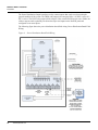
5.0 System Configuration
This section provides wiring diagrams for each of the NetAXS system configurations.
5.1 RS-485 Connection via PCI-2
This connection supports thirty-one NetAXS™ Access Controller panels for each drop line. It has
been reviewed by Underwriters Laboratories Incorporated (UL). Note that PCI-2 units can also be
wired in interior, as well as in endpoint, positions. See Figure 20 on page 33 and Figure 21 on page 34.
Because UL has reviewed the NetAXS panel only as a standalone system, the computer terminal,
NetAXS gateway panel, and N-485_PCI-2 adapter appear in these sections only to illustrate the
installation and programming of the NetAXS panel.
Figure 18:
RS-485 Connection via PCI-2
COM Port
RS-232 (50 Ft. Max.)
RS-485 (4,000 Ft.)
Terminal
RS-485 Cable
RS485
NetAXS Panels
Red/White
Black/Green
RS-485 COM
TB7-1 (RS485+)
TB7-2 (RS485-)
TB7-3 (RS485 COM)
4,000 ft. (1,200 m) max, 24 AWG, 2 twisted pairs
shield, 120 ohm, 23 pf (HAS part no. NCP2441-
485
ote
DIP Switch Settings
S1-S5 Panel Address
S6: OFF
J36 OPEN
J37 OPEN
NetAXS
Panel
It is recommended to Ear
NetAXS enclosure
EG
n y ar
roun
one side of cable
EG
NetAXS Access Control Unit NX4L1 Installation Guide, Document 7-901099, Revision A
EG
31
NetAXS™ NX4L1 Installation
System Configuration
5.2 RS-485 Connection via NetAXS™
This connection supports thirty-one NetAXS™ Access Controller panels for each drop line. It has
been reviewed by UL. However, because UL has reviewed the NetAXS panel only as a standalone
system, the computer terminal and NetAXS gateway panel appear in this illustraton only to show the
installation and programming of the NetAXS panel.
Figure 19:
RS-485 Connection via NetAXS™
COM Port
RS-232 (50 Ft. Max.)
RS-485 (4,000 Ft.)
NetAXS
Getaway
Terminal
etAXS
etail
RS-485 Cable
NetAXS Panel
TB7-1 (RS485+)
TB7-2 (RS485-)
TB7-3 (RS485 COM)
4,000 ft. (1,200 m) max, 24 AWG, 2 twisted pairs
120 ohm, 23 pf (HAS part no. NCP2441-
s
E
See RS-485
Cable Note
Only Earth Ground (EG)
one side of cable
EG
EG
It is recommended to Earth Ground (EG)
each NetAXS enclosure individually
32
www.honeywell.com
NetAXS™ NX4L1 Installation
System Configuration
5.3 RS-485 Connections with Multidrop Panels at Both Ends of the Cable
You can connect Multidrop panels at both ends of an RS-485 cable via either a NetAXS™ panel or a
PCI-2 device. This connection has not been reviewed by UL.
Figure 20:
RS-485 Connection via NetAXS™ with Multidrop Panels at Both Ends
RS-485 (4,000 Ft.)
COM Port
Terminal
RS-485 Cable
NetAXS Panels
TB7-1 (RS485+)
TB7-2 (RS485-)
TB7-3 (RS485 COM)
-485
Note
4,000 ft. (1,200 m) max, 24 AWG, 2 twisted pairs with
shield, 120 ohm, 23 pf (HAS part no. NCP2441-TN)
DIP Switch Settings
S1-S5 Panel Address
S6: OFF
J36 CLOSED
J37 CLOSED
s
NetAXS
Panel
EG
Only Earth Ground (EG)
one side of cable
EG
Only Earth Ground (EG)
one side of cable
EG
EG
EG
It is recommended to Earth Ground (EG) each NetAXS enclosure individual
NetAXS Access Control Unit NX4L1 Installation Guide, Document 7-901099, Revision A
33
NetAXS™ NX4L1 Installation
System Configuration
Figure 21:
RS-485 Connection via PCI-2 with Multidrop Panels at Both Ends
COM Port
RS-232 (50 Ft. Max.)
RS-485 (4,000 Ft.)
Terminal
4
485
ote
DIP Switch Settings
S1-S5 Panel Address
S6: OFF
J36 OPEN
J37 OPEN
NetAXS
Panel
EG
EG
n y ar
roun
one side of cable
EG
one side of cable
EG
EG
It is recommended to Earth Ground (EG) each NetAXS enclosure individually
34
www.honeywell.com
EG
NetAXS™ NX4L1 Installation
System Configuration
5.4 RS-232 Connection
This connection supports one NetAXS™ Access Controller panel for each COM port. It has been
reviewed by UL. However, because UL has reviewed the NetAXS panel only as a standalone system,
the computer terminal and NetAXS gateway panel appear in this section only to illustrate the
installation and programming of the NetAXS panel.
Figure 22:
RS-232 Connection
CBL50 (RS-232) 50 Ft. Max.
COM 1
COM 2
Terminal
CBL50
(RS-232)
50 Ft. Max.
DIP Switch Settings
S1 - S5: Panel Address
S6: OFF
NetAXS
Panel
NetAXS
Panel
It is recommended to Earth Ground (EG)
each NetAXS enclosure individually
EG
EG
CBL50 (RS-232)
RS-232
(DB9)
8
5
2
3
7
RJ-45
Request To Send (RTS)
Signal Ground (GND)
Receive Data (RXD)
Transmit Data (TXD)
Clear To Send (CTS)
2
3
4
5
7
9-Pin COM 1 or COM 2 to RJ-45 on NetAXS Panel
NetAXS Access Control Unit NX4L1 Installation Guide, Document 7-901099, Revision A
35
NetAXS™ NX4L1 Installation
System Configuration
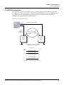
5.5 Ethernet Connection
This connection supports a maximum of 255 IP connections per server. It has not been reviewed
by UL.
Figure 23:
Ethernet Connection
NIC
100BaseT (CAT 5) 328 Ft. Max.
Terminal
RS-485 Multidrop
RS-485 Multidrop
DIP Switch Settings
S1-S5 Panel Address
S6: OFF
NetAXS
Panel
EG
36
www.honeywell.com
EG
EG
EG
NetAXS™ NX4L1 Installation
System Configuration
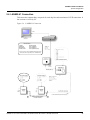
5.6 LANSRLU1 Connection
This connection supports thirty-one panels for each drop line and a maximum of 255 IP connections. It
has not been reviewed by UL.
Figure 24: LANSRLU1 Connection
NIC
HUB/SWITCH
Terminal
HUB/SWITCH
RS-485 Cable
RS485
NetAXS Panels
Red/White
Black/Green
RS-485 COM
TB7-1 (RS485+)
TB7-2 (RS485-)
TB7-3 (RS485 COM)
4,000 ft. (1,200 m) max, 24 AWG, 2 twisted pairs with
shield, 120 ohm, 23 pf (HAS part no. NCP2441-TN)
LANSRLU1
RJ-45
RS-232 (50 Ft.)
See RS-485 Cable note
EG
EG)
each NetAXS enclosure individually
EG
Only Earth Ground (EG)
one side of cable
EG
NetAXS Access Control Unit NX4L1 Installation Guide, Document 7-901099, Revision A
37
NetAXS™ NX4L1 Installation
System Configuration
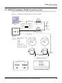
5.7 RS-485 Short Haul Modem Connection via PCI-2
This connection supports thirty-one NetAXS™ Access Controller panels for each drop line. It has not
been reviewed by UL.
Figure 25:
RS-485 Short Haul Modem Connection via PCI-2
RS232 Cable
PC
(DB-9)
RS-232, 50 Ft. Max.
Terminal
MODEM
DTE
(Straight)
2 TX
3 RX
5 Comm
DCE
(Null)
2 (TX)
2 (RX)
3 (RX) or 3 (TX)
7 (GND) 7 (GND)
SHM-B-ASYNCH
Short Haul Modem
(J1 RS-232 Connector)
RS-485 Cable
NetAXS Panels
DCE
DN
RX +
RX -
TX +
TX GROUND
TB7-1 (RS485+)
TB7-2 (RS485-)
TB7-3 (RS485 COM)
(Jumper)
DIS
RTSIDTR
CONTROL
4,000 ft. (1,200 m) max, 24 AWG, 2 twisted pairs with
shield, 120 ohm, 23 pf (HAS part no. NCP2441-TN)
DTE
DIP Switch Settings
S1-S5 Panel Address
S6: OFF
J36: CLOSED
J37: CLOSED
DIP Switch Settings
S1-S5 Panel Address
S6: OFF
J36: OPEN
J37: OPEN
(S2 Loopback)
5279.9
Feet
(S2 Loopback)
See RS-485
cable note
EG
RTSIDTR
CONTROL
DN
(Jumper)
DIS
EG
SHM-B-ASYNCH
Short Haul Modem
(J1 RS-232 Connector)
RS232 Cable
DI
S1:
S2:
S3:
S4:
S5:
S6:
S7:
S8: OFF )19,200 Baud Rate)
38
www.honeywell.com
N-485-PCI-2
(RS-232 50 Ft. Max.)
Male 9 Pin
Male 25 Pin
Refer to 485-PCI/NetAXS Panel
Connection Detail diagram
PC
(DB-9)
2 TX
3 RX
5 Comm
MODEM
DTE
(Straight)
DCE
(Null)
2 (TX)
2 (RX)
3 (RX) or 3 (TX)
7 (GND) 7 (GND)
NetAXS™ NX4L1 Installation
System Configuration
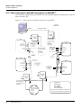
5.8 RS-485 Short Haul Modem Connection via NetAXS™
Thirty-one NetAXS™ Access Controller panels for each drop line. It has not been reviewed by UL.
Figure 26:
RS-485 Short Haul Modem Connection via NetAXS™
RS232 Cable
PC
(DB-9)
RS-232, 50 Ft. Max.
MODEM
DTE
(Straight)
2 TX
3 RX
5 Comm
DCE
(Null)
2 (TX)
2 (RX)
3 (RX) or 3 (TX)
7 (GND) 7 (GND)
Terminal
SHM-B-ASYNCH
Short Haul Modem
(J1 RS-232 Connector)
RS-485 Cable
NetAXS Panels
DCE
DN
RX +
RX -
TX +
TX GROUND
TB7-1 (RS485+)
TB7-2 (RS485-)
TB7-3 (RS485 COM)
(Jumper)
DIS
RTSIDTR
CONTROL
4,000 ft. (1,200 m) max, 24 AWG, 2 twisted pairs with
shield, 120 ohm, 23 pf (HAS part no. NCP2441-TN)
DTE
DIP Switch Settings
S1-S5 Panel Address
S6: OFF
J36: CLOSED
J37: CLOSED
DIP Switch Settings
S1-S5 Panel Address
S6: OFF
J36: OPEN
J37: OPEN
(S2 Loopback)
5279.9
Foot
(S2 Loopback)
EG
NetAXS
Panel
EG
NetAXS
Panel
See RS-485
cable note
RTSIDTR
CONTROL
DN
Only Earth Ground (EG)
one side of cable
EG
(Jumper)
DIS
EG
It is recommended to Earth Ground (EG) each
NetAXS enclosure individually
SHM-B-ASYNCH
Short Haul Modem
(J1 RS-232 Connector)
RS232 Cable
DIP Switch Settings
S1-S5 Panel Address
S6: ON
J36: CLOSED
J37: CLOSED
NetAXS
Panel
(RS-232 50 Ft. Max.)
CBL50
Male 9 Pin
Male 25 Pin
NetAXS Access Control Unit NX4L1 Installation Guide, Document 7-901099, Revision A
PC
(DB-9)
2 TX
3 RX
5 Comm
MODEM
DTE
(Straight)
DCE
(Null)
2 (TX)
2 (RX)
3 (RX) or 3 (TX)
7 (GND) 7 (GND)
39
NetAXS™ NX4L1 Installation
System Configuration
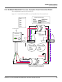
5.9 RS-232 Short Haul Modem Connection
One NetAXS™ Access Controller panel for each loop. It has not been reviewed by UL.
Figure 27:
RS-232 Short Haul Modem Connection
RS232 Cable
PC
(DB-9)
RS-232, 50 Ft. Max.
Terminal
MODEM
DTE
(Straight)
2 TX
3 RX
5 Comm
DCE
(Null)
2 (TX)
2 (RX)
3 (RX) or 3 (TX)
7 (GND) 7 (GND)
SHM-B-ASYNCH
Short Haul Modem
DN
RX +
RX -
TX +
TX GROUND
DCE
(Jumper)
DIS
RTSIDTR
CONTROL
(DEC/DTE)
DTE
(S2 Loopback)
DIP Switch Settings
S1-S5 Panel Address
S6: OFF
5279.9
Foot
(S2 Loopback)
EG
NetAXS
Panel
(DEC/DTE)
RTSIDTR
CONTROL
DN
(Jumper)
DIS
CBL50
It is recommended to
Earth Ground (EG) each
NetAXS enclosure
individually
SHM-B-ASYNCH
Short Haul Modem
(J1 RS-232 Connector)
RS232 Cable
(RS-232 50 Ft. Max.)
Male 9 Pin
40
www.honeywell.com
Male 25 Pin
PC
(DB-9)
2 TX
3 RX
5 Comm
MODEM
DTE
(Straight)
DCE
(Null)
2 (TX)
2 (RX)
3 (RX) or 3 (TX)
7 (GND) 7 (GND)
NetAXS™ NX4L1 Installation
System Configuration
5.10 M-56K Dial-up Modem, RS-485 Connection via Hub
Thirty-one NetAXS™ Access Controller panels for each drop line. It has not been reviewed by UL.
Figure 28:
M-56K Dial-up Modem, RS-485 Connection via Hub
M-56K
FAX/MODEM
COM Port
Straight Through Cable
Female 9 Pin
Terminal
Male 25 Pin
(RX) 2
(TX) 3
Analog
Phone
Line
Remote DIP Switch Settings
(1, 3, 8 ON) (2, 4, 5, 6, 7 OFF)
3 (RX)
2 (TX)
(Comm) 5
7 (Comm)
N-485-HUB-2
Dedicated
analog
phone
line
recommended
M-56K
FAX/MODEM
RS-232 (50 ft.)
Remote DIP Switch Settings
(1, 3, 8 ON) (2, 4, 5, 6, 7 OFF)
RS-485 (4,000 ft.)
Refer to 485PCI-2 /NetAXS
Panel
Connection
Detail diagram
DIP Switch Settings
S1: ON
S2: ON
S3: ON
S4: ON
S5: ON
S6: ON (Ack/Nak ON)
S7: ON
S8: OFF (19,200 Baud Rate)
DIP Switch Settings
S1-S5 Panel Address
S6: OFF
J36: OPEN
J37: OPEN
DIP Switch Settings
S1-S5 Panel Address
S6: OFF
J36: CLOSED
J37: CLOSED
NetAXS
Panel
NetAXS
Panel
EG
EG
EG
Only Earth Ground (EG)
one side of cable
See RS-485
Cable Note
EG
It is recommended to Earth Ground (EG)
each NetAXS enclosure Individually
RS-485 Cable
DB 9 / DB 25 Connectors
13
Female
1
25
14
5
9
1
6
NetAXS Panels
Male
13
1
25
14
5
9
1
6
TB7-1 (RS485+)
TB7-2 (RS485-)
TB7-3 (RS485 COM)
4,000 ft. (1,200 m) max, 24 AWG, 2 twisted pairs with
shield, 120 ohm, 23 pf (HAS part no. NCP2441-TN)
NetAXS Access Control Unit NX4L1 Installation Guide, Document 7-901099, Revision A
41
NetAXS™ NX4L1 Installation
System Configuration
5.11 M-56K Dial-up Modem, RS-485 Connection via NetAXS™
Thirty-one NetAXS™ Access Controller panels for each drop line. It has not been reviewed by UL.
Figure 29:
M-56K Dial-up Modem, RS-485 Connection via NetAXS™
M-56K
FAX/MODEM
COM Port
Straight Through Cable
Female 9 Pin
Terminal
Male 25 Pin
(RX) 2
(TX) 3
3 (RX)
2 (TX)
(Comm) 5
CBL50
7 (Comm)
Male 9 Pin
NetAXS
Panel
Analog
Phone
Line
Remote DIP Switch Settings
(1, 3, 8 ON) (2, 4, 5, 6, 7 OFF)
Dedicated
analog
phone
line
recommended
M-56K
FAX/MODEM
Male 25 Pin
RS-232 (50 ft.)
Remote DIP Switch Settings
(1, 3, 8 ON) (2, 4, 5, 6, 7 OFF)
RS-485 (4,000 ft.)
DIP Switch Settings
S1-S5 Panel Address
S6: OFF
J36: OPEN
J37: OPEN
DIP Switch Settings
S1-S5 Panel Address
S6: OFF
J36: CLOSED
J37: CLOSED
DIP Switch Settings
S1-S5 Panel Address
S6: ON
J36: CLOSED
J37: CLOSED
NetAXS
Panel
NetAXS
Panel
EG
EG
EG
DB 9 / DB 25 Connectors
13
Female
1
25
14
5
9
42
www.honeywell.com
1
6
RS-485 Cable
Male
13
1
25
14
5
9
It is recommended to
Earth Ground (EG)
each NetAXS enclosure
Individually
1
6
NetAXS Panels
TB7-1 (RS485+)
TB7-2 (RS485-)
TB7-3 (RS485 COM)
4,000 ft. (1,200 m) max, 24 AWG, 2 twisted pairs with
shield, 120 ohm, 23 pf (HAS part no. NCP2441-TN)
See RS-485
Cable Note
EG
NetAXS™ NX4L1 Installation
System Configuration
5.12 Fiber Converter to RS-485 Connection via PCI-2
This connection supports thirty-one NetAXS™ Access Controller panels for each drop line. It has not
been reviewed by UL.
Figure 30: Fiber Converter to RS-485 Connection via PCI-2
Refer to N-485-PCI-2/NetAXS Access
Controller Panel Connection Detail diagram
COM Port
RS-485
(4000 Ft. Max.)
RS-232 (50 Ft. Max.)
Terminal
FC485
RS-485 Fiber Converter
EG
RXD
PWR
TXD
FC485
RS-485 Fiber Converter
RS-485 Comm.
RS-485 Positive (+)
EG
RXD
PWR
TXD
RS-485 Negative (-)
RS-485 Comm.
RS-485 Positive (+)
RS-485 Negative (-)
DIP Switch Settings
S1-S5 Panel Address
S6: OFF
J36: CLOSED
J37: CLOSED
Fiber RXD
Fiber TXD
h ground
Fiber RXD
Fiber TXD
FC485
RS-485 Fiber Converter
RXD
PWR
TXD
FC485
RS-485 Fiber Converter
RS-485 Comm.
RS-485 Positive (+)
RXD
PWR
TXD
RS-485 Negative (-)
RS-485 Comm.
RS-485 Positive (+)
RS-485 Negative (-)
Fiber RXD
Fiber TXD
Fiber RXD
Fiber TXD
NetAXS
Panel
EG
EG
It is recommended to
Earth Ground (EG)
each NetAXS enclosure
Individually
EG
RS-485 Cable
RS485
EG
DIP Switch Settings
S1-S5 Panel Address
S6: OFF
J36: OPEN
J37: OPEN
Red/White
Black/Green
RS-485 COM
NetAXS Panels
TB7-1 (RS485+)
TB7-2 (RS485-)
TB7-3 (RS485 COM)
4,000 ft. (1,200 m) max, 24 AWG, 2 twisted pairs with
shield, 120 ohm, 23 pf (HAS part no. NCP2441-TN)
NetAXS Access Control Unit NX4L1 Installation Guide, Document 7-901099, Revision A
43
NetAXS™ NX4L1 Installation
System Configuration
5.13 Fiber Converter to RS-485 Connection via NetAXS™
This connection supports thirty-one NetAXS™ Access Controller panels for each drop line. It has not
been reviewed by UL.
Figure 31: Fiber Converter to RS-485 Connection via NetAXS™
RS-485
(4000 Ft. Max.)
COM Port
RS-232 (50 Ft. Max.)
Terminal
FC485
RS-485 Fiber Converter
EG
RXD
PWR
TXD
FC485
RS-485 Fiber Converter
RS-485 Comm.
RS-485 Positive (+)
EG
RXD
PWR
TXD
RS-485 Negative (-)
)
DIP Switch Settings
S1-S5 Panel Address
S6: OFF
J36: CLOSED
J37: CLOSED
Fiber RXD
Fiber TXD
RS-485 Comm.
RS-485 Positive (+)
RS-485 Negative (-)
h ground
Fiber RXD
Fiber TXD
FC485
RS-485 Fiber Converter
RXD
PWR
TXD
FC485
RS-485 Fiber Converter
RS-485 Comm.
RXD
PWR
TXD
RS-485 Positive (+)
RS-485 Negative (-)
RS-485 Comm.
Fiber RXD
RS-485 Positive (+)
Fiber TXD
RS-485 Negative (-)
Fiber RXD
Fiber TXD
NetAXS
Panel
EG
EG
It is recommended to
Earth Ground (EG)
each NetAXS enclosure
Individually
EG
RS-485 Cable
EG
NetAXS Panels
DIP Switch Settings
S1-S5 Panel Address
S6: OFF
J36: OPEN
J37: OPEN
44
www.honeywell.com
TB7-1 (RS485+)
TB7-2 (RS485-)
TB7-3 (RS485 COM)
4,000 ft. (1,200 m) max, 24 AWG, 2 twisted pairs with
shield, 120 ohm, 23 pf (HAS part no. NCP2441-TN)
NetAXS™ NX4L1 Installation
System Configuration
5.14 N-485-PCI-2/NetAXS™ Access Controller Panel Connection Detail
This configuration has not been reviewed by UL.
Figure 32:
N-485-PCI-2/NetAXS™ Access Controller Panel Connection Detail
485 Interface ConnectionTypes
DIP Switch Settings
S1:ON
S2:ON
S3:ON
S4:ON
S5:ON
S6:ON
S7:ON
S8:OFF
RS-485
NetAXS Panel
N-485-PCI-2
N-485-HUB-2
N-485-PCI-2L
COM Port
M-56K Modem
LANSRL100 or LANSRLU1
To Serial Connection
See 485 interface
connection note
Ground Shield
DO NOT CONNECT or
GROUND SHIELD
N-485-PCI-2
NetAXS TB7
1
2
3
N
MO
COM
WHITE
GREE
N
BLAC
K
RED
DIP Switch Settings
S1-S5:Panel Address
S6: OFF
J36: CLOSED
J37: CLOSED
NetAXS TB7
1
2
3
DIP Switch Settings
S1-S5:Panel Address
S6: OFF
J36: OPEN
J37: OPEN
Ground only one
side of cable shield
X
485
Common
X
Shield
485 +
485 4,000 ft.(1,200 m) max,24 AWG,2 twisted pairs with
shield,120 ohm,23 pf (HAS part no.NCP2441-TN)
NetAXS Access Control Unit NX4L1 Installation Guide, Document 7-901099, Revision A
45
NetAXS™ NX4L1 Installation
System Configuration
5.15 NetAXS™/NetAXS™ Access Controller Panel Connection Detail
Figure 33: NetAXS™/NetAXS™ Access Controller Panel Connection Detail
Ground Shield
DO NOT CONNECT or
GROUND SHIELD
To Serial Connection
NetAXS TB7
DO NOT
CONNECT
SHIELD
X
485
Common
2
3
DIP Switch Settings
S1-S5:Panel Address
S6: OFF
J36: CLOSED
J37: CLOSED
DIP Switch Settings
S1-S5:Panel Address
S6: ON
J36: CLOSED
J37: CLOSED
NetAXS Panel
1
NetAXS TB7
DIP Switch Settings
S1-S5:Panel Address
S6: OFF
J36: OPEN
J37: OPEN
Ground only one
side of cable shield
Shield
3
1
2
NetAXS TB7
46
www.honeywell.com
X
485 +
485 4,000 ft.(1,200 m) max,24 AWG,2 twisted pairs with
shield,120 ohm,23 pf (NCI part no.NCP2441-TN)
1
2
3
NetAXS™ NX4L1 Installation
NetAXS™ Startup
6.0 NetAXS™ Startup
6.1 LED Operation
When the panel wiring is complete, turn on the power. It might take a few minutes for
the panel to complete the power-up sequence. When the board does initialize, verify
that the appropriate LEDs identified in the following figure are in accord with the
descriptions in Table 7 on page 48.
Figure 34:
System, Relay and Power LEDs
RDR 3
Host RS232 and
Downstream LEDs
Ethernet Status
LEDs
RDR 4
Run LED
RS485 LED
RDR 1
RDR 2
Relay
Status
LEDs
Relay Status
LEDs
Power
NetAXS Access Control Unit NX4L1 Installation Guide, Document 7-901099, Revision A
47
NetAXS™ NX4L1 Installation
NetAXS™ Startup
The following table indicates the status associated with each LED.
Table 7 LED Status
LED
PWR
RUN
H485
H232
DS
COM
LINK
RLY
RDR
GREEN
Power
OK
RUN
Heart
Beat
Multidrop
Receive
Data
RS232
Receive
Data
Downstream
Receive
Data
100Mbit
Link
OK
Relay
Active
Flash at
read
RED
N/A
N/A
Transmit
Data
Transmit
Data
Transmit
Data
N/A
N/A
N/A
N/A
AMBER
N/A
N/A
TX &
RX
Data
TX &
RX
Data
TX &
RX
Data
N/A
TX &
RX
Data
N/A
N/A
OFF
Power
Off
Malfunction
No
Com
No
Com
No
Com
10Mbit
No
Link
Relay
Off
Normal
Note: The Ethernet/COM status LED will be green even if no cable is attached.
48
www.honeywell.com
NetAXS™ NX4L1 Installation
Hardware Specifications
7.0 Hardware Specifications
7.1 Relay Contacts
Eight Form-C SPDT relays, 2 A @ 28 VDC (PTC limited).
7.2 Reader Interface
• Reader Power: 12.4 VDC nominal with 600 mA combined current with
readers and AUX Power.
• Reader LED Output: Open collector driver capable of sinking up to 8 mA.
• Reader Tamper: Supervised or non-supervised input.
• Reader Data Input: TTL compatible inputs.
• Reader Buzzer Output: Open collector driver capable of sinking 8 mA at
15 VDC.
7.3 Maximum Output Loading
• Maximum current for any of the four reader outputs is 600 mA.
• Maximum current for any of the eight relay outputs on the HPACM8 is 2 A.
• Maximum battery charge current for the two batteries wired in series is
700 mA.
• Maximum combined current of the four reader outputs and the two auxiliary
outputs is 600 mA.
• Maximum combined current of the two auxiliary outputs (if used without the
four reader outputs) is 500 mA.
• Combined current of the eight relay outputs on the HPACM8 relay board is
2 A.
7.4 Common Connections
Common connections are all connected internally. They are not connected to the panel
chassis.
7.5 Mechanical
• Enclosure Dimension: 17.7 inches (450 mm) W x 23.9 inches (607 mm) H x
3.54 inches (90 mm) D.
• Enclosure Weight:
– With two batteries (including the door): 33.70 lbs
– With one battery (including the door): 28.90 lbs
– Without batteries (including the door): 24.25 lbs
NetAXS Access Control Unit NX4L1 Installation Guide, Document 7-901099, Revision A
49
NetAXS™ NX4L1 Installation
Hardware Specifications
7.6 Environment
• Temperature: 0C to 49C operating, -55C to +85C storage.
• Humidity: 5% to 85% RHNC.
7.7 Communications and Wiring
Table 8 Communications and Wiring
Communication Type
Description
Maximum
Panels
Maximum Distance:
Feet (Meters)
Direct to COM Port
CBL50, RS-232 Cable
9-pin to RJ-45
1
50 (15)
N-485-PCI-2
RS-485 9-pin to CPU
31
4,000 (1,220)
M-9600-LA (LO)/
N-485-PCI-2
Lease-line Modem to
RS-485
31
NA/4,000 (NA/122)
SHM-B-ASYNC/
N-485-PCI-2
Short-haul Modem to
RS-485
31
5,280/4,000 (1,610/1,220)
SHM-B-ASYNC/CBL50
Short-haul Modem to
RS-232
1
5,280/50 (1,610/15)
M-56K/N-485-HUB-2
Dial-up Modem to RS-485
31
NA/4,000 (NA/1,220)
Fiber converter to RS-485
31
10,000/4,000 (3,050/1,220)
Modems
Fiber
FC485
50
www.honeywell.com
NetAXS™ NX4L1 Installation
Hardware Specifications
7.8 Reader Wiring
Table 9 Reader Wiring
Cable Specifications
Description
AWG
Maximum Distance:
Feet (Meters)
Readers
NC1861-BL
6 Conductor, Shielded
18
500 (153)
Twisted Pair, Shielded
18
2,000 (610)
Twisted Pair, Shielded
18
2,000 (610)
Alarm Input
NC1821-GR
Relay Outputs
NC1821-GR
NetAXS Access Control Unit NX4L1 Installation Guide, Document 7-901099, Revision A
51
NetAXS™ NX4L1 Installation
Hardware Specifications
7.9 NX4L1 Panel Wiring Diagram
RESERVED FOR
FUTURE USE
NetAXS Panel Wiring Diagram
Panel Tamper/IN14
Common
ACFAIL/IN 13
Figure 35:
Enclosure Tamper Switch
RS-232 *
RS-232
Ethernet
* Ethernet
Host RS485+
Host RS485Common
LED/OUT 11
D0
D1
Common
+12VDC
Tamper/IN 9
Buzzer/OUT 15
LED/OUT 12
D0
D1
Common
+12VDC
Tamper/IN 10
Buzzer/OUT 16
Door1 REX/IN 1
Common
Door1 Status/IN 2
Door2 REX/IN 3
Common
Door2 Status/IN 4
Aux + 12VDC
Aux Common
Relay 1 N.O.
Relay 1 Com
Relay 1 N.C.
Relay 2 N.O.
Relay 2 Com
Relay 2 N.C.
Relay 3 N.O.
Relay 3 Com
Relay 3 N.C.
Relay 4 N.O.
Relay 4 Com
Relay 4 N.C.
}
TB13
TB4
}
TB14
TB3
TB15
TB2
TB16
TB1
IN 1
IN GND
IN 2
IN GND
IN 3
IN GND
IN 4
IN GND
IN 5
IN GND
IN 6
IN GND
IN 7
IN GND
IN 8
IN GND
TB17
FIRE PANEL IN +
FIRE PANEL IN CNTRL +
CNTRL -
Reader 4 *
Door 3/4
INPUTS *
AUX 12VDC *
Override
}External
Control *
AC Power Light
* Output 8
* Output 7
RF Line
Filter
6ET3
* Output 6
+_ +_
L N
* Output 5
24V
BAT DC
* Door 4
AC Fail
BAT Fail
Line
Ground
Neutral
TB12
XPORT
TB5
Reader 3 *
OUT 1 NC
OUT 1 COM
OUT 1 NO
NEG #1
OUT 2 NC
OUT 2 COM
OUT 2 NO
NEG #2
OUT 3 NC
OUT 3 COM
OUT 3 NO
NEG #3
OUT 4 NC
OUT 4 COM
OUT 4 NO
NEG #4
OUT 5 NC
OUT 5 COM
OUT 5 NO
NEG #5
OUT 6 NC
OUT 6 COM
OUT 6 NO
NEG #6
OUT 7 NC
OUT 7 COM
OUT 7 NO
NEG #7
OUT 8 NC
OUT 8 COM
OUT 8 NO
NEG #8
}
TB11
1
* Door 1
* AUX 12VDC
N.C.
COM
N.O.
N.C.
COM
N.O.
6
TB6
} Expansion RS-485*
}
}
DIP switches
}
Power Supply
AL600ULXB
* Door 1/2
INPUTS
Expansion RS485-/B
Expansion RS485+/A
Buzzer/OUT 17
Tamper/IN 11
+12VDC
Common
D1
D0
LED/OUT 13
Buzzer/OUT 16
Tamper/IN 12
+12VDC
Common
D1
D0
LED/OUT 14
DR3 REX/IN 5
Common
DR3 Status/IN 6
DR4 REX/IN 7
Common
DR4 Status/IN 8
Aux Common
Aux + 12VDC
Relay 5 N.C.
Relay 5 Com
Relay 5 N.O.
Relay 6 N.C.
Relay 6 Com
Relay 6 N.O.
Relay 7 N.C.
Relay 7 Com
Relay 7 N.O.
Relay 8 N.C.
Relay 8 Com
Relay 8 N.O.
AC/DC AC/DC +
TB10
* Door 3
* Reader 2
TB9
TB7
}
}
* Reader 1
TB8
* Door 2
}
* Host RS-485
N G L
Line
Ground
Neutral
Green
Brown
Blue
Optional
AC Inlet*
Honeywell P/N
100-00049
* Represents field wiring (Class 2 power limited)
52
www.honeywell.com
Battery
CASIL CA1270
_
+
Battery
CASIL CA1270
HAS 3-000066
12VDC, 7AHr
+
_
HAS 712BNP
12VDC, 7AHr
NetAXS™ NX4L1 Installation
Maintenance
Maintain at least a .25-inch distance between the non-power limited wiring (115
VAC/60 Hz input wiring, power line filter wiring, 24 VDC wiring, battery
backup/charger wiring, and battery-to-battery wiring) and all other wiring, which is
power-limited Class 2 wiring.
Note:
8.0 Maintenance
Perform the following maintenance on the NetAXS™ enclosure:
• Change the CASIL CA1270 lead-acid backup batteries (HAS part number
3-000066) every two to two-and-a-half years.
Caution: Do
not connect an uncharged battery to the panel.
• Oil the lock once per year
• Use the following procedure to change the 3.5 A, 250 V, Bussman type AGC
fuse in the AL600ULXB Power Supply module. See Figure 1 on page 6 to
identify the location of the Power Supply’s fuse and the four mounting screws
that secure the protective Power Supply cover.
Warning: Be
sure to disconnect the AC power before removing the Power
Supply cover.
Warning: To reduce the risk of fire, replace the fuse only with a 3.5 A, 250 V,
Bussman type AGC fuse.
1.Disconnect the AC power.
2.Remove the protective Power Supply cover by removing the four mounting
screws (see Figure 1 on page 6).
3.Remove the translucent fuse cover.
4.Replace the fuse with a new 3.5 A, 250 V fuse.
5.Re-attach the translucent fuse cover.
6.Re-attach the protective Power Supply cover with the four mounting screws.
7.Re-connect the AC power.
NetAXS Access Control Unit NX4L1 Installation Guide, Document 7-901099, Revision A
53
NetAXS™ NX4L1 Installation
Maintenance
• Use the following procedure to change the 3, 250 V, Bussman type GMA fuse
in the power inlet terminal block.
Warning: Be
sure to disconnect the AC power before removing the fuse holder
from the power inlet terminal block.
Warning: To
reduce the risk of fire, replace the fuse only with a 3 A, 250 V,
Bussman type GMA fuse.
1.Disconnect the AC power.
2.Remove the fuse holder from the power inlet terminal block (see Figure 1 on
page 6 to identify the location of the power inlet terminal block).
3.Replace the blown fuse in the lower section of the fuse holder with the new
fuse. The upper section of the fuse holder provides a convenient location for
a spare fuse.
4.Slide the fuse holder back into the power inlet terminal block.
5.Re-connect the AC power.
54
www.honeywell.com
NetAXS™ NX4L1 Installation
Troubleshooting
9.0 Troubleshooting
Table 10 Troubleshooting Problems and Solutions
Problem
Solution
The panel
powers up, but it
does not respond
to any
communication,
cards reads, or
input activation.
Ensure that the Address DIP switches are set to a value other than zero.
Turn off the power (including battery), change the settings, and re-apply
the power.
No
communications
exist with the
Ethernet port.
Only a panel set to be a Gateway (DIP switch 6 = ON) will have
communications on the Ethernet port. If you need to use that port to
access the panel, turn off the power (including the battery), change the
switch setting, and reapply the power. Note that if the panel is normally
not a Gateway on a Multidrop communication bus, then the Host
RS-485 connection (TB7) should also be disconnected while DIP
switch 6 is ON. After completion of the Ethernet session, turn off the
power (including the battery), change the switch setting, re-connect the
Host RS-485 terminal block, and re-apply the power.
The IP address is
incorrectly set to
verify the value.
If you are connecting directly to a computer instead of going through a
router or hub, use a cross-over Ethernet cable.
The N1000
panels on the
Multidrop bus
do not report.
N1000 panels will not communicate to a NetAXS™ panel that is
configured as a Gateway. Replace all of the N1000 panels with
NetAXS™, or replace the Gateway panel with an N-485-PCI-2 device.
The BAD CRC
counter is
incrementing
every minute.
Two or more panels on the Multidrop Bus have the same panel address.
Verify that each panel has a unique address setting on DIP switch
positions 1-5.
A dropline panel
in standalone
mode using
RS-232 may
unexpectedly fill
its buffer.
The preferred solution is to configure the standalone panel through the
Web server as a Gateway and use the board PCI and AckNak communications. This also gives the user a more secure and reliable communications line.
Another solution is to execute a new command that will allow the user
to turn the Tesla flow control off:
_U=<pn>_D (disable flow control)
This prevents the panels from inadvertently filling their buffers.
To turn the Tesla flow control back on:
_U=<pn>_E (enable flow control)
NetAXS Access Control Unit NX4L1 Installation Guide, Document 7-901099, Revision A
55
NetAXS™ NX4L1 Installation
Technical Support
The NetAXS™ EOL network is AC-coupled. There is no resistance difference
between the RS-485 positive and negative terminals if the EOL network is on or off
(J36 and J37).
Note:
10.0 Technical Support
10.1 Normal Support Hours
Monday through Friday, 7:00 a.m. to 7:00 p.m. Central Standard Time (CST), except
company holidays: (800) 323-4576.
10.2 Web
For technical assistance please visit http://www.honeywellaccess.com
56
www.honeywell.com
NetAXS™ Standalone Operation
A
A.1 Basic Standalone Operations
A.1.1 Card Read / Door Lock Operation
1. Present a card to a reader.
2. The reader sends the card number to a reader input on the panel.
3. The panel searches its database and:
• If it is a valid card, then energize the door relay associated with the
particular reader input. The card is valid when it is in the card database
on the panel and the current time and date conforms to the time zone
associated with the card.
• If it is not a valid card, the door relay remains locked.
A.1.2 Door Egress / Door Lock / Door Status Operation
1. Activate the door egress input.
2. The panel energizes the door relay associated with the particular door egress
input for a default time of 10 seconds.
3. If the door status goes from close to open to close again during the 10 second
door open period, the door relay will be immediately de-energized.
NetAXS Access Control Unit NX4L1 Installation Guide, 7-901099, Revision A
57
NetAXS™ Standalone Operation
Standalone Settings
A.2 Standalone Settings
A.2.1 NetAXS™ Panel Hardware Settings
• Configure the system with an RS-232 connection according to Figure 22 on
page 35.
• Set DIP switches 1 through 5 to define the panel number (see Table 5 on
page 27). Panel number 0 is not valid.
• Set DIP switch 6 to the OFF position to place the panel into the Multidrop
mode.
• Use a personal computer’s serial communications port (COM1 or COM2) and
a terminal emulation program to configure the NetAXS™ panel for normal
operation.
A.2.2 Communication Settings
•
•
•
•
•
Baud Rate: 115200
Data Bits: 8
Parity: None
Stop Bits: 1
Flow Control: None
A.2.3 Emulation Settings
• Echo typed characters locally: YES
• Line Delay: 500 milliseconds
A.2.4 Verifying Communications
1. Press the spacebar.
2. Press the carriage return <CR>. “S?” appear for every online panel and
indicates proper communication between the terminal and panel.
58
www.honeywell.com
NetAXS™ Standalone Operation
Standalone Commands
A.3 Standalone Commands
Caution: Use the following commands, in the order they are listed, to configure the
NetAXS™ panel.
1. T command: Sets the panel’s Time
2. D command: Sets the panel’s Date
3. L command: Creates Time zones for use by the cards
4. C command: Adds or Deletes cards from the panel
5. W command: Program each input for either NO/NC and Supervised or NON
Supervised operation
6. P command: Sets interlocks between input points and/or output points
In all examples, the underbar “_” indicates a “space” character and <CR>
indicates a carriage return.
Note:
A.3.1 T (Time) Command
_T=pn_hh:mm<CR>
Variables:
pn = panel number (1-31)
hh = hours (0-23) (Military time)
mm = minutes (00-59)
Example #1:
_T=1_08:30<CR>
This command would set panel 1 to a time of 8:30 AM.
Example #2
_T=6_18:15<CR>
This command would set panel 6 to a time of 6:15 PM.
NetAXS Access Control Unit NX4L1 Installation Guide, 7-901099, Revision A
59
NetAXS™ Standalone Operation
Standalone Commands
A.3.2 D (Date) Command
_D=pn_mm/dd/yyyy_day<CR>
Variables:
pn = panel number (1-31)
mm = month number (1-12)
dd = day number (1-31)
yyyy = year number (ex 2007, 1999, etc.)
day = day of week (1-7):
1 = Monday
2 = Tuesday
3 = Wednesday
4 = Thursday
5 = Friday
6 = Saturday
7 = Sunday
The day of week setting is a hold-over from an old command. The panel using
the mm/dd/yyyy information will automatically configure panel to the correct day of
the week, regardless of the setting selected in day of week. But the command still
requires a value to be entered in its place of 1-7.
Note:
Example #1:
_D=1_01/09/2007_5<CR>
This command would set panel 1 to a date of 1/9/2007 and to Tuesday as the day of
the week.
Example #2:
_D=25_12/14/2009_7<CR>
This command would set panel 25 to a date of 12/14/2009 with a day of week being
Monday.
60
www.honeywell.com
NetAXS™ Standalone Operation
Standalone Commands
A.3.3 L (Time Zone) Command
_L=pn_tz_h1:m1-h2:m2_days<CR>
Variables:
pn = panel number (1-31)
tz = time zone number (1-255)
h1 = start time zone: hours (00-23) (Military time)
m1 = start time zone: minutes (00-59)
h2 = end time zone: hours (00-23) (Military time)
m2 = end time zone: minutes (00-59)
days = days of week valid values as listed below:
1 = Monday
2 = Tuesday
3 = Wednesday
4 = Thursday
5 = Friday
6 = Saturday
7 = Sunday
0 = Holiday 1
8 = Holiday 2
9 = Holiday 3
00:00 is the earliest time possible and 23:59 is the latest time possible. A single
time zone cannot be made to span mid-night, through the use of extended commands
we can simulate this. For more information, please seek the guidance of technical
support.
Note:
Example #1:
_L=5_10_08:00-17:00_1_2_3_4_5<CR>
This command would configure panel 5 to add a time zone entry to time zone number
10 ranging from 8AM to 5PM and would be valid during Monday, Tuesday,
Wednesday, Thursday, and Friday.
Example #2:
_L=25_45_16:00-23:59_0_6_7_8_9<CR>
This command would configure panel 25 to add a time zone entry to time zone
number 45 ranging from 4PM to 11:59PM and would be valid during Saturday,
Sunday, Holiday, 1, 2, and 3.
NetAXS Access Control Unit NX4L1 Installation Guide, 7-901099, Revision A
61
NetAXS™ Standalone Operation
Standalone Commands
A.3.4 C (Card Add) Command
_C=pn_code_time zone_dev<CR>
Variables:
pn = panel number (1-31)
code = card number (range depends on card format)
time zone = time zone number the card will follow (1-255)
dev = device numbers card will work with, see below:
1 = card reader #1
2 = card reader #2
3 = card reader #3
4 = card reader #4
Example #1:
_C=6_12345_10_1_2_3_4<CR>
This command would configure panel 6 to add a card entry of 12345 to the panels
database, that will be valid on reader 1, 2, 3, and 4 during the times and days specified
by time zone 10.
Example #2
_C=18_52989_120_1_3<CR>
This command would configure panel 18 to add a card entry of 52989 to the panels
database, that will be valid on reader 1 and 3 during the times and days specified by
time zone 120.
A.3.5 C (Card Delete) Command
_C=pn_code<CR>
Variables:
pn = panel number (1-31)
code = card number (range depends on card format)
Example #1:
_C=6_12345<CR>
This command would remove card 12345 from panel 6.
Example #2
_C=18_52989<CR>
This command would remove card 52989 from panel 18.
62
www.honeywell.com
NetAXS™ Standalone Operation
Standalone Commands
A.3.6 W (Input) Command
_W=pn_input_{SO|SC|NO|NC}<CR>
Variables:
SO: Supervised normally open
SC: Supervised normally closed
NO: Non-supervised normally open
NC: Non-supervised normally closed (default)
Example:
_W=1_9_SO<CR>
Input 9 has been programmed as supervised, normally open on panel 1.
A.3.7 P (Interlock) Command
_P=pn_I/O_[number]_I/O[number]_{D|E|F|N|P}_
{D|E|F|N|P}<CR>
Parameters:
number: for an input number, the range is 1-96; for output, 0-78
D: De-energize
E: Energize
F: Follow
N: No action
P: Pulse
Example:
_P=1_I_5_O_3_E_D
When Input 5 is triggered, Output 3 energizes.
When Input 5 returns to its normal state, Output 3 de-energizes.
NetAXS Access Control Unit NX4L1 Installation Guide, 7-901099, Revision A
63
NetAXS™ Standalone Operation
Standalone Commands
A.3.8 Flow Control Disable/Enable Command
(Use this command only for a dropline panel using RS-232 in standalone mode)
_U=[panel name]_{D|E}
Parameters:
D: Disable
E: Enable
Example:
_U=30_D
This disables the flow control on panel 30 and prevents the panel’s buffers from
filling. After a hard re-set of the panel, the flow control is re-enabled.
64
www.honeywell.com
NetAXS™ Standalone Operation
NetAXS™ Panel Defaults
A.4 NetAXS™ Panel Defaults
A.4.1 Reader Ports
The panel accepts a Wiegand serial data packet from the card reader. If the card is in
the database, the associated relay is activated. If the card is not in the database, the
relay state is unchanged.
The following are the default reader port to relay associations:
Reader Number
Controls...
1
Relay 1 (Output 1)
2
Relay 2 (Output 2)
3
Relay 3 (Output 3)
4
Relay 4 (Output 4)
A.4.2 Reader LED Outputs
The Reader LED output defaults to toggle the card reader LED from Red to Green for
two seconds when a valid card is presented. No LED color change (other then a
possible momentary change depending on reader used) occurs if the card is not in the
database.
The following are the default reader LED port to output associations:
Reader LED
Controls...
Reader 1
Output 11
Reader 2
Output 12
Reader 3
Output 13
Reader 4
Output 14
NetAXS Access Control Unit NX4L1 Installation Guide, 7-901099, Revision A
65
NetAXS™ Standalone Operation
NetAXS™ Panel Defaults
A.4.3 Reader Tamper Inputs
The card readers have a Tamper signal wired to the NetAXS™ panel. This is a
two-state input configured as a Normally Closed contact.
The following are the default Reader Tamper Input to Panel Input associations:
Tamper LED
Reports as...
Tamper 1
Input 9
Tamper 2
Input 10
Tamper 3
Input 11
Tamper 4
Input 12
A.4.4 Door Egress Inputs
The panel has a Request-To-Exit (Egress) input for each door. The default condition is
a two-state input configured as Normally Closed contact. When the egress input is
active, the associated output relay will be active.
The following are the default egress input associations:
66
Egress input
Controls relay...
Panel input
Reports as...
1
1
SP1
Input 1
2
2
SP3
Input 3
3
3
SP5
Input 5
4
4
SP7
Input 7
www.honeywell.com
NetAXS™ Standalone Operation
NetAXS™ Panel Defaults
A.4.5 Door Status Inputs
The panel has a Door Status input for each door. The default condition is a two-state
input configured as a Normally Closed contact.
The following are the default door status input associations:
Door Status input
Panel input
Reports as...
1
SP2
Input 2
1
SP4
Input 4
1
SP6
Input 6
1
SP8
Input 8
A.4.6 ACFAIL and Panel Tamper Inputs
The panel has the following two additional generic inputs that can be used as generic
inputs or as either External Power Fail or Enclosure Tamper inputs. The default
condition is a two-state input configured as Normally Closed. Input 14 is a special
case, since it reports in as two inputs (inputs 14 and 20). Input 14 can be used as a
generic input, but input 20 is used for the Enclosure Tamper alarm. An active External
Power Fail input indicates that the system is operating from the battery current, not
from the primary input power. An inactive External Power Fail input indicates that the
system is operating from the primary input power.
Generic input
Panel input
Reports as...
Generic/External Power Fail
SP9
Input 13
Generic/Enclosure Tamper
SP10
Inputs 14 and 20
NetAXS Access Control Unit NX4L1 Installation Guide, 7-901099, Revision A
67
NetAXS™ Standalone Operation
NetAXS™ Panel Defaults
A.4.7 Additional Generic Outputs
The panel has the following four additional generic form C relay outputs that can be
programmed using the P command:
68
Relay output
Controls...
5
Output 5
6
Output 6
7
Output 7
8
Output 8
www.honeywell.com
Honeywell Access Systems
135 W. Forest Hill Avenue
Oak Creek, WI 53154
United States
800-323-4576
414-766-1798 Fax
www.honeywellaccess.com
Specifications subject to change
without notice.
© Honeywell. All rights reserved.
Document 7-901099, Revision A