1
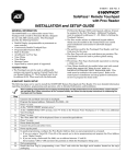
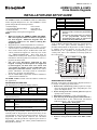
K0022V3 3/09 Rev. A ADEMCO 6150V & 6160V Voice Remote Keypads INSTALLATION AND SETUP GUIDE GENERAL INFORMATION UL NOTE: ADEMCO 6150V cannot be used for commercial fire applications. KEYPAD DISPLAYS AND LEDS The keypads have the following display features: Model 6150V 6160V Fixed Word Display X 2-Line Alpha Display X 2-Digit Zone Identifier X Custom Zone Descriptors X The following table identifies the keypad’s LEDs and associated functions: LED Function ARMED Lights red when the system is armed in any mode. READY Lights green when the system is "ready" to be armed. MESSAGE Function Keys A B C D • [1] and [*] [*] and [#] [3] and [#] NONE Function keys must be held down for at least 2 seconds to activate the programmed function. If functions other than panics are assigned to the programmable function keys, programmed panics must be initiated by pressing the programmed key pair. • FUNCTION KEY LABELS A set of adhesive-backed labels with some typical function symbols (i.e., fire, police, personal emergency, etc.) is provided. These labels can be placed on or next to the keys to identify each key's function for the end user (as determined by the capability and programming of the control panel; refer to the installation and setup guide for the control panel). A ARMED B 1 OFF 2 AWAY VOLUME 3 STAY RECORD READY 4 MAX 5 TEST 6 BYPASS MESSAGE 7 INSTANT 8 CODE 9 CHIME READY 0 C MIC STATUS VOICE PLAY SIDE VIEW # FUNCTION D MOUNTING RELEASE SNAPS (Remove case back by pushing up the 2 "snaps" along the keypad's bottom edge and pulling the case apart.) WIRING AND INSTALLATION Keypads can be surface mounted using drywall anchors or to a single- or double-gang electrical box. 1. Remove the case back by pushing up the two "snaps" along the keypad’s bottom edge and pulling the case apart. See diagram above. 2. Route wiring from the control panel through the opening in the case back. 3. Mount the case back to a wall or electrical box. 4. Wire directly from the keypad’s terminal block to the terminal block on the control board. (See Wiring Table that follows.) Use only 16-24 AWG wire. Keypad G Flashes red when message waiting or lights red (steady) when in record mode. PROGRAMMABLE FUNCTION KEYS The keypad's programmable function keys [A, B, C] are normally used for keypad panic functions, but they can be programmed for other special functions instead. If they are programmed for other special functions, the associated keypad key pairs still provide the respective panic alarm (if programmed). Refer to the control panel’s Installation & Setup Guide for details. Equivalent Key Pairs 6160V-001-V1 The ADEMCO 6150V and ADEMCO 6160V are addressable remote keypads designed for use with ADEMCO control panels and provide the following features: • Backlit Display • Voice Chime • Programmable Function Keys • Voice Status • Built-in Sounder • Message Center • Supervised by control panel (if supported) Notes: • When used with the ADEMCO VISTA-15P/VISTA20P control panels, address 16 must be assigned to the first keypad. Additional keypads must be assigned to address 17 – 23. Refer to Setting The Keypad Options. • Keypad keys are continuously backlit for convenience. • Permanent display backlighting is an option on some controls (refer to control panel’s instructions for details). • Voice Chime should only be enabled when used with control panels that support the "chime by zone" mode (e.g., VISTA-15P/VISTA-20P). This mode must be enabled at the control panel. Refer to the control panel's installation and setup guide for information on how to program the chime mode. • Use only zone descriptors supported by this keypad. If using zone descriptors not supported by this keypad, you must turn voice status and voice chime off. Table 1 is a list of applicable zone descriptors and index entries. Refer to the control panel’s installation and setup guide for information about how to program zone descriptors. • For the 6160V ONLY, supervision must be enabled for commercial fire installations. 5. 6. Wiring Table (All Keypads) Control Panel Wire Color Data In Green – – Aux Pwr (GND) Black + + Aux. Pwr Red Y Data Out Yellow Re-attach the keypad to the case back. Remove clear protective film from LEDs (6160V only). SETTING THE KEYPAD OPTIONS The procedures that follow are used to set the keypad address, voice chime mode, and additional voice keypad mode. Setting The Keypad Address When used with the VISTA-15P/VISTA-20P control panels, address 16 must be assigned to the first Keypad. Additional Keypads must be set at 17 - 23 and must be enabled additionally in control programming (fields *190 - *196). The keypad can either be set for an address of 00-30 or for non-addressable mode (31). The default keypad address is 31. For valid address settings for your keypad, refer to the control panel's Installation & Setup Guide. Note: • If unable to enter the address mode, power down, power up, and try again. • If 10 seconds pass with no key entry, the keypad automatically exits the address mode. You must power down, power up, and start the address mode again. • The keypad will not enter the address mode if the control panel is in programming mode. 1. Apply power to the keypad. 2. Within 60 seconds of applying power to the keypad, press and hold down the [1] key and [3] key at the same time for 3 seconds. The current keypad address will be displayed. 3. Press "00". The current address is cleared. 4. Enter desired keypad address. 5. Press [*] to save the displayed address and enter the Voice Chime mode. "VOICE CHIME" (alpha keypad) or "C" (fixed keypad) is displayed along with the selected mode "1" or "0". Setting The Voice Chime Mode 6. Press [1] to set the Voice Chime mode on or press [0] to set the Voice Chime mode off. 7. Press [*] to save the displayed Voice Chime mode and enter the Additional Console voice keypad mode. "ADDITIONAL CON" (alpha keypad) or "A" (fixed keypad) is displayed along with the selected mode "1" or "0". Note: Setting Voice Chime mode off does not effect the voice status or alarm annunciation. Setting The Additional Console Mode The Additional Console mode must be set for all voice keypads being used. 8. Set the voice keypad Additional Console mode as follows: a. On the Primary voice keypad, press [0] to set the Additional Console mode to NO. b. On any secondary voice keypads, press [1] to set Additional Console mode to YES. 9. Press [*] to save the mode. VIEWING THE KEYPAD ADDRESS Press and hold down the [1] key and [3] key at the same time for about 3 seconds. The current address is displayed. No key entry is allowed. Press any key to exit or wait 10 seconds to exit the viewing mode. OPERATING THE KEYPAD For operating instructions, see the User Guide for the control panel used with this keypad. SPECIFICATIONS Physical: 6150V: 4-7/8"H x 6-1/4"W x 1"D 6160V: 5-5/16"H x 7-3/8"W x 1-3/16"D Displays: 6150V: Fixed-Word LCD (backlit) 6160V: 2 x 16 Alpha-Numeric Super twist LCD (backlit) Sounder: Speaker Electrical: Voltage: +12VDC (power-limited) Current: 6150V: 160mA (ARMED LED lit, LCD backlight and sounder on) reduces to 60mA when panel is operating in standby mode (backlight off). 6160V: 190mA (ARMED LED lit, LCD backlight and sounder on) reduces to 60mA when panel is operating in standby mode (backlight off). NFPA72 Compliant. TABLE 1. ZONE DESCRIPTORS AND INDEX ENTRIES ALARM 002 DOOR 057 KITCHEN 105 PATIO 146 UPSTAIRS 207 ATTIC 009 EMERGENCY 067 LAUNDRY 106 POLICE 151 UTILITY 208 BABY 012 EXIT 071 LIBRARY 109 POOL 152 WINDOW 217 BACK 013 FIRE 079 LIVING 113 ROOM 162 YARD 223 BASEMENT 016 FLOOR 080 MAIN 122 SHED 168 ZONE 225 BATHROOM 017 FRONT 085 MASTER 123 SHOP 170 1ST 228 BEDROOM 019 GARAGE 089 MEDICAL 125 SIDE 173 2ND 230 CLOSED 040 GUN 094 MOTION 131 SLIDING 175 3RD 232 DEN 050 HALL 095 OFFICE 136 SMOKE 176 DETECTOR 052 HOUSE 099 OPEN 138 STORAGE 185 DINING 053 INSIDE 101 PANIC 144 SUPERVISED 190 REFER TO THE INSTALLATION INSTRUCTIONS FOR THE CONTROL PANEL WITH WHICH THIS DEVICE IS USED FOR WARRANTY INFORMATION AND LIMITATIONS OF THE ENTIRE ALARM SYSTEM. For the latest warranty information, please go to: http://www.security.honeywell.com/hsc/resources/wa/index.html 2 Corporate Center Drive, Suite 100, P.O. Box 9040, Melville, NY 11747 Copyright 2009 Honeywell International Inc. www.security.honeywell.com ÊK0022V36Š K0022V3 3/09 Rev. A