1
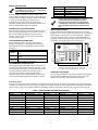
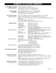
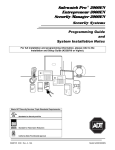
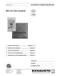
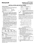
K14804V1 6/08 Rev. A
6160VPADT
SafePass Remote Touchpad
with Prox Reader
TM
INSTALLATION and SETUP GUIDE
GENERAL INFORMATION
The 6160VPADT is an addressable remote Voice
Touchpad with a built-in Proximity Reader, designed
for use with ADT control panels. This Touchpad
provides the following features:
• Backlit Display (programmable as permanent on
some controls)
• Continuously Backlit Touchpad Keys
• Programmable Function Keys
• Built-in Sounder
• Arm/Disarm via Prox Tag
• Voice Chime
• Voice Status
• Message Center
• Supervised by control panel (if supported).
Installation Notes
• The Touchpad can only be used on addressable
systems and cannot be used on Control Panels that
use Keypad Address 31. The Touchpad must be set
for address 00-30. When used with the Safewatch
•
•
•
•
•
Pro/Security Manager 3000 control panels, address 16 must
be assigned to the first Touchpad. Additional Touchpads
must be assigned to addresses 17 – 23. (Refer to Setting the
Touchpad Options.)
The Prox reader utilizes an additional keypad address,
which must be enabled at the Control Panel (see control
panel installation instructions for allowable keypad
addresses).
The partition used for the Touchpad, Prox Reader, and User
Code must be the same.
The Prox Tags will only arm and disarm one partition. The
Prox Reader cannot be used to perform global arming
operations.
Presenting a Prox Tag is functionally equivalent to entering
a 4 digit user code.
Voice Chime should only be enabled when used with control
panels that support the "chime by zone" mode (e.g.,
SAFEWATCH PRO/SECURITY MANAGER 3000). This
mode must be enabled at the control panel. Refer to the
control panel's installation and setup guide for information
on how to program the chime mode.
6160VPADT QUICK SETUP
The following steps can be used to install the 6160VPADT Remote Touchpad and Prox Reader. For more detailed information
regarding installation, programming and operation, refer to Detailed Information and Installation.
When installing wiring between the Touchpad’s terminal block and the terminal block on the Control Panel, connect only the
red and black Aux. Power connections at the Touchpad initially, and follow the step-by-step instructions for addressing the
Touchpad and Prox Reader.
Step
1.
2.
3.
4.
5.
6.
7.
8.
9.
10.
11.
12.
13.
14.
Action
Connect red and black wires only to touchpad.
Program the keypad address. (Safewatch Pro 3000 = 16)
Press * to save.
At the “VOICE CHIME” prompt, press *.
At the “ADDITIONAL CON” prompt, enter “0” if this is the Primary Voice Touchpad, or “1” if this is an additional
Voice Touchpad.
Press * to save.
The “Prox Addr? XX” will be displayed. Enter an unused keypad address.
Press * to save.
Power down the panel.
Connect the green and yellow wires.
Power up the panel.
In panel programming, configure the Prox Reader Address that you just programmed as a keypad.
a. If you are using a Vista-128, Vista-50 or like panels, go to device programming and program the Prox Address
as an “Alpha Console.”
b. If you are using a Safewatch Pro 3000, use an address between 17 and 23.
Go to location *190 to *196 and enter the partition in which the Touchpad is being used.
Exit programming.
Enroll the Prox Tag by programming a new “User” code with the four-digit serial number located on the tag’s
packaging.
STEP-BY-STEP INSTALLATION INSTRUCTIONS
Touchpads can be surface mounted using drywall
anchors or to a single- or double-gang electrical box.
1. Remove the case back by pushing in the two
"snaps" along the Touchpad’s bottom edge and
pulling the case apart. See diagram above.
2. Route wiring from the control panel through the
case back openings or the knockouts located on the
sides.
3. Mount the case back to a wall or electrical box.
Do not connect the ECP Data In or Data Out until
directed to do so. If the Touchpad’s Prox Reader
detects the presence of ECP Data In and Out
connections during address programming mode,
it will exit to “normal” mode.
4.
Wire directly from the Touchpad’s terminal block
to the terminal block on the control panel. (Refer to
the Wiring Table.) Connect only the red and
black Aux. Power connections at the
Touchpad. Use only 16-24 AWG wire.
Wiring Table
Touchpad
5.
6.
Control Panel
Wire Color
G
Data In
Green
–
– Aux Pwr (GND)
Black
+
+ Aux. Pwr (POS)
Red
Y
Data Out
Yellow
Re-attach the Touchpad to the case back.
Remove clear protective film from LCD display.
SETTING THE TOUCHPAD OPTIONS
The procedures that follow are used to set the
Touchpad address, voice chime mode, and additional
console modes.
Setting the Touchpad Address
1. Apply power to the Touchpad.
2. Within 60 seconds of applying power to the Touchpad, press
and hold down the [1] and [3] keys at the same time for 3
seconds. The current Touchpad address will be displayed.
3. Press "00". The current address is cleared.
4. Enter desired two-digit Touchpad address.
5. Press [✱] to accept the displayed address and enter the
Voice Chime Mode. "VOICE CHIME" is displayed along
with the selected mode "1" or "0".
Setting the Voice Chime Mode
Setting Voice Chime mode off does not effect the
voice status or alarm annunciation.
1. Press [1] to set the Voice Chime mode on or press [0] to set
the Voice Chime mode off.
2. Press [✱] to save the displayed Voice Chime mode and
enter the Additional Console Voice Touchpad mode.
"ADDITIONAL CON" is displayed along with the selected
mode "1" or "0".
Setting the Additional Console Mode
The Additional Console mode must be set for all Touchpads
being used.
1. Set the Touchpad Additional Console mode as follows:
a. On the Primary Touchpad, press [0] to set the
Additional Console mode to NO.
b. On any secondary Touchpads, press [1] to set Additional
Console mode to YES.
2. Press [✱] to save the mode and enter Prox Reader Address
Mode.
Setting the Prox Reader Address
1. After exiting “additional console” mode, the Prox Reader
will begin communicating with the Touchpad, and the
Touchpad will display “Prox Addr? XX” on the first line.
1. XX = the current ECP Address. The Prox Reader
address cannot be the same as the Touchpad
address. Select an address between 01 and 30
(default = address 23.)
2. Make sure you enable the prox reader address as
a keypad in the control panel.
When used with the Safewatch Pro/Security
Manager 3000 control panels, address 16 must
be assigned to the first Touchpad. Additional
Touchpads must be set at 17 - 23 and must be
enabled additionally in control programming
(fields *190 - *196).
The Touchpad addresses being used for the
Touchpad and the Prox Reader must be enrolled
in the control panel.
Swiping a Prox Tag when the system is in
programming mode may cause programming
fields to receive invalid entries.
The Touchpad may be set for address 00-30 or for nonaddressable mode (31). The default Touchpad address
is 31. For valid address settings for your Touchpad,
refer to the control panel's Installation & Setup Guide.
Notes:
• If installed with an older non-addressable panel
(using address 31), the prox feature cannot be used.
• If unable to enter the address mode, power down,
power up, and try again.
• If 10 seconds pass with no key entry, the Touchpad
automatically exits the address mode. You must
power down, power up, and start the address mode
again.
• The Touchpad will not enter the address mode if the
control panel is in programming mode.
2. Set the current address to "00": Press [0] to clear the
current "tens" digit. The cursor moves to the "ones" digit
position. Press [0] to clear the current "ones" digit. The
cursor moves back to the "tens" digit position.
3. Enter the appropriate address: Enter the proper "tens"
digit of the address. The cursor moves to the "ones" digit
position. Enter the proper "ones" digit of the address.
4. Press the [*] key to save the entry. The Touchpad will beep
three times confirming the address is accepted, and the
first digit of the address will flash. You can re-enter the
address if desired.
5. Power down the Touchpad.
6. Remove the case back.
7 Connect the green and yellow data in and data out wires
at the control panel. Once connected, any Touchpad not
enabled in the control at that point will be blank.
8. Re-attach the Touchpad to the case back.
9.
-2-
Install the Prox Reader location labels on the Touchpad.
(Refer to Figure 1.)
ENROLLING PROX TAGS
Function Keys
Swiping a Prox Tag when the system is in
programming mode may cause programming
fields to receive invalid entries.
A
B
C
D
Each Prox Tag is enrolled as a “User” in the alarm
system. When enrolling the Tags, the last four digits of
the Tag’s serial number is used as the User Code. Refer
to the control’s User Guide for instructions on
programming user codes. When programming is
complete, test the system to ensure that each Prox Tag
arms and disarms the system as specified.
• Function keys must be held down for at least 2
seconds to activate the programmed function.
• If functions other than panics are assigned to the
programmable function keys, programmed panics
must be initiated by pressing the programmed key
pair.
VIEWING THE TOUCHPAD ADDRESS
During normal operation, press and hold down the [1]
key and [3] key at the same time for about 3 seconds.
The current address is displayed. No key entry is
allowed. Press any key to exit or wait 10 seconds to
exit the viewing mode.
FUNCTION KEY LABELS
A set of adhesive-backed labels with some typical function
symbols (i.e., fire, police, personal emergency, etc.) is provided.
These labels can be placed on or next to the keys to identify
each key's function for the end user (as determined by the
capability and programming of the control panel; refer to the
installation and setup guide for the control panel).
TOUCHPAD DISPLAYS AND LEDS
The Touchpad provides a two-line alphanumeric
display and custom zone descriptors. The following
table identifies the Touchpad’s LEDs and associated
functions:
ARMED
Function
A
Lights red when the system is armed in any
mode.
READY
Lights green when the system is "ready" to be
armed.
MESSAGE
Flashes red when message waiting or lights
(steady) when in record mode.
B
1
ARMED
READY
MESSAGE
C
MIC
OFF
2
AWAY
3
STAY
RECORD
VOLUME
4
5
TEST
6 BYPASS
7 INSTANT
8
CODE
9
READY
0
STATUS
VOICE
PLAY
SIDE VIEW
CHIME
#
FUNCTION
D
PROGRAMMABLE FUNCTION KEYS
The Touchpad's programmable function keys [A, B, C]
are normally used for panic functions, but they can be
programmed for other special functions instead. If they
are programmed for other special functions, the
associated Touchpad key pairs still provide the
respective panic alarm (if programmed). Refer to the
control panel’s Installation & Setup Guide for details.
MOUNTING RELEASE SNAPS
(Remove case back by pushing up the 2 "snaps" along
the keypad's bottom edge and pulling the case apart.)
6160vADT-50-001-V1
LED
Equivalent Key Pairs
[1] and [*]
[*] and [#]
[3] and [#]
NONE
OPERATING THE KEYPAD
For operating instructions, see the User Guide provided with
this keypad. For additional information, refer to the User
Guide for the control panel used with this keypad.
Zone Descriptors
Only the zone descriptors listed in Table 1 are supported by this Touchpad. If using zone descriptors not supported by this
Touchpad, you must turn voice status and voice chime off. Table 1 provides is a list of applicable zone descriptors and index
entries. Refer to the control panel’s Installation and Setup Guide for information about how to program zone descriptors.
TABLE 1. ZONE DESCRIPTORS AND INDEX ENTRIES
ALARM
002
DOOR
057
KITCHEN
105
PATIO
146
UPSTAIRS
207
ATTIC
009
EMERGENCY
067
LAUNDRY
106
POLICE
151
UTILITY
208
BABY
012
EXIT
071
LIBRARY
109
POOL
152
WINDOW
217
BACK
013
FIRE
079
LIVING
113
ROOM
162
YARD
223
225
BASEMENT
016
FLOOR
080
MAIN
122
SHED
168
ZONE
BATHROOM
017
FRONT
085
MASTER
123
SHOP
170
1ST
228
BEDROOM
019
GARAGE
089
MEDICAL
125
SIDE
173
2ND
230
3RD
232
CLOSED
040
GUN
094
MOTION
131
SLIDING
175
DEN
050
HALL
095
OFFICE
136
SMOKE
176
DETECTOR
052
HOUSE
099
OPEN
138
STORAGE
185
DINING
053
INSIDE
101
PANIC
144
SUPERVISED
190
-3-
SPECIFICATIONS
Physical:
Display:
Sounder:
Electrical:
Voltage:
Current:
NFPA72
5-5/16"H x 7-3/8"W x 1-3/16"D
2 x 16 Alpha-Numeric
Supertwist LCD (backlit)
Speaker
+12VDC (power-limited)
190mA (Status LED lit and/or flashing, LCD backlight and sounder on, Prox Reader active) reduces to
60mA when panel is operating in standby mode (LCD backlight and sounder off).
Compliant
WARRANTY INFORMATION
For the latest warranty information, please go to:
www.honeywell.com/security/hsc/resources/wa
FEDERAL COMMUNICATIONS COMMISSION (FCC) PART 15 STATEMENT
This equipment has been tested to FCC requirements and has been found acceptable for use. The FCC requires the following
statement for your information:
This equipment generates and uses radio frequency energy and if not installed and used properly, that is, in strict accordance
with the manufacturer's instructions, may cause interference to radio and television reception. It has been type tested and found
to comply with the limits for a Class B computing device in accordance with the specifications in Part 15 of FCC Rules, which
are designed to provide reasonable protection against such interference in a residential installation. However, there is no
guarantee that interference will not occur in a particular installation. If this equipment does cause interference to radio or
television reception, which can be determined by turning the equipment off and on, the user is encouraged to try to correct the
interference by one or more of the following measures:
• If using an indoor antenna, have a quality outdoor antenna installed.
• Reorient the receiving antenna until interference is reduced or eliminated.
• Move the radio or television receiver away from the receiver/control.
• Move the antenna leads away from any wire runs to the receiver/control.
• Plug the receiver/control into a different outlet so that it and the radio or television receiver are on different branch
circuits.
If necessary, the user should consult the dealer or an experienced radio/television technician for additional suggestions. The
user or installer may find the following booklet prepared by the Federal Communications Commission helpful:
"Interference Handbook"
This booklet is available under Stock No. 004-000-00450-7 from the U.S. Government Printing Office, Washington, DC 20402.
The user shall not make any changes or modifications to the equipment unless authorized by the Installation Instructions or
User's Manual. Unauthorized changes or modifications could void the user's authority to operate the equipment.
FCC / IC STATEMENT
This device complies with Part 15 of the FCC Rules, and RSS 210 of Industry Canada. Operation is subject to the following two
conditions: (1) This device may not cause harmful interference, and (2) This device must accept any interference received,
including interference that may cause undesired operation.
ADT Security Services, Inc.
One Town Center Road
Boca Raton, FL 33486
Copyright © 2008
ÊK14804V15Š
K14804V1 6/08 Rev. A