1
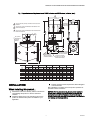
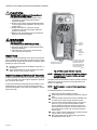
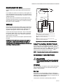
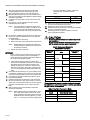
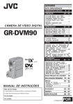
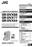
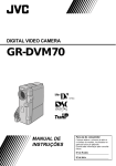
V4055F,G Fluid Power Actuator
with Manual Control
PRODUCT DATA
FEATURES
• Fast opening time of 13 seconds at 120 V, 60 Hz.
• Maximum closing time, is 1 second, which meets approval
body requirements.
• Unit available with FM approved proof of closure switch.
• Red “OPEN” indicator attached to the actuator piston will
show if the valve is even slightly open; yellow “SHUT”
indicator on the valve stem will show only when the gas
valve is fully closed.
• Ambient temperature rating of -40°F to +150°F (-40°C to
+66°C).
• Valve and actuator may be mounted in any position.
• Optional, field-adjustable, spdt auxiliary switch, rated at
112 hp (0.37 kW), may be added in the field.
• Standard enclosure meets NEMA 1 (IP30) general
purpose requirements.
• Red light indicates when valve is ready to open.
• Rocker switch allows manual operation of valve.
APPLICATION
• Valve closes on power loss.
The V4055F and G fluid power gas valve actuators are for use
with the V5055 valve for gas safety shutoff applications to
control the gas supply of commercial and industrial burners.
NOTICE: Per Industry standards, the actuator is required a
conduit seal or a cable type that is sealed be installed in a
device that can result in a flammable liquid flow through a
conduit or cable to an electrical ignition source in the event of
a seal leakage or diaphragm failure.
Contents
Application ........................................................................
Specifications ...................................................................
Operation ..........................................................................
Ordering Information ........................................................
Installation ........................................................................
Wiring ...............................................................................
Checkout and Service ......................................................
65-0029-02
1
2
2
2
3
5
5
V4055F,G FLUID POWER ACTUATOR WITH MANUAL CONTROL
SPECIFICATIONS
Models:
V4055G Fluid Power Actuator with Manual Control-for use
with the V5055 valve. Provides ON-OFF control. Rated for 5
PSI.
Closing Time: 1 sec maximum when de-energized.
Ambient Operating Temperature Rating:
-40°F to +150°F (-40°C to +66°C) for 60 Hz models; -10°F to
+158°F (-23°C to +70°C) for 50 Hz and 50/60 Hz models.
V4055F-Same as V4055G except: for use with V5055C only.
Meets UL and FM proof of closure requirements.
Mounting Means:
Actuator mounts directly to valve bonnet with 2 setscrews,
positioned 90 angular degrees apart. Valve and actuator
can be mounted in any position.
Table 1. Auxiliary Switch And Valve-closed Indication Switch
Ratings: 112 hp (0.37 kW)a
LOAD
120 V
240 V
Full Load
9.8 A
4.9A
Locked Rotor
58.5 A
29.4 A
a Maximum
1800 VA.
Mounting Dimensions: See Fig. 1.
Accessories:
133568 Auxiliary Switch Bag Assembly.
133569 Valve-Closed Indication Switch Bag Assembly.
Approvals: UL and FM. IRI Approvable.
total connected power to both switches (if used) is
Electrical Ratings: See Table 2.
Nominal Opening Time: 13 seconds:
Table 2. Electrical Ratings.
Opening (Fast)
Voltage and
Frequency
120/60
Inrush
5.4
W
71.0
Holding
A
VA
1.33
160
OPERATION
1.
2.
3.
The red READY TO OPEN light will be on if there is
power to the actuator and the rocker switch is in the center position.
To open the valve depress the rocker switch to the
VALVE OPEN position and hold until the valve is open
(Red READY TO OPEN light turns off). The valve will
close if the rocker switch is released from the VALVE
OPEN position with the red READY TO OPEN light on.
4.
W
9.5
A
0.12
VA
14
To close the valve depress rocker switch to VALVE
CLOSED position. The rocker switch stays in the valve
closed position when released.
The valve automatically closes on power loss. It must be
manually reopened using the rocker switch.
ORDERING INFORMATION
When purchasing replacement and modernization products from your TRADELINE® wholesaler or distributor, refer to the
TRADELINE® Catalog or price sheets for complete ordering number. If you have additional questions, need further information,
or would like to comment on our products or services, please write or phone:
1. Your local Honeywell Environmental and Combustion Controls Sales Office (check white pages of your phone directory).
2. Honeywell Customer Care
1885 Douglas Drive North
Minneapolis, Minnesota 55422-4386
3. http://customer.honeywell.com or http://customer.honeywell.ca
International Sales and Service Offices in all principal cities of the world. Manufacturing in Belgium, Canada, China, Czech
Republic, Germany, Hungary, Italy, Mexico, Netherlands, United Kingdom, and United States.
65-0029-02
2
V4055F,G FLUID POWER ACTUATOR WITH MANUAL CONTROL
Fig. 1. Approximate mounting dimensions of V4055 actuators and V5055 valves, in inches. (mm).
2
6-3/4 (172)
3-23/32 (95)
1
ALLOW 4 INCHES (102 MM) CLEARANCE FOR ACTUATOR
REMOVAL.
2
ADD 1/8 INCH (3 MM) TO DIMENSION FOR MODELS WITH
NEMA 4 ENCLOSURE.
3
ADD 1/4 INCH (6 MM) TO DIMENSION FOR A MODELS WITH
NEMA 4 ENCLOSURE.
5 (127)
27/32 (22)
KNOCKOUT
FOR1/2 INCH
CONDUIT (4)
1-9/32
(33)
A
1
3
3/4 (19) BOLT
HOLES [8] ON
3-3/4 (95)
RADIUS
C
B
E
9-3/16
(233)
1/2 INCH NPT UPSTREAM
TAP AND PLUG (OPTIONAL
ON DOMESTIC MODELS)
D
1/8 OR 1/4 INCH NPT
DOWNSTREAM TAP
AND PLUG (OPTIONAL
ON DOMESTIC MODELS)
OCTAGON
F
1/4 INCH NPT UPSTREAM
TAP AND PLUG (1/4 BSP ON
INTERNATIONAL MODELS)
D
VALVE
SIZE
INCH
3/4
1
1-1/4
1-1/2
2
2-1/2
3
4
DIM A
IN.
DIM C
DIM B
DIM D
DIM E
DIM F
MM
IN.
MM
IN.
MM
IN.
MM
IN.
13-1/8
13-1/8
13-1/8
333.5
333.5
333.5
2-3/4
2-3/4
2-3/4
70.0
70.0
70.0
8-3/16
8-3/16
8-3/16
208.0
208.0
208.0
5-3/4
5-3/4
5-3/4
146.0
146.0
146.0
2-1/4
2-1/4
2-1/4
57.0
57.0
57.0
13-1/8
13-1/4
13-3/4
13-3/4
16-3/16
333.5
2-3/4
70.0
336.5
2-7/8
73.0
349.0
3-3/8
85.5
349.0
3-3/8
85.5
411.0 5-13/16 128.0
8-3/16
8-5/16
8-13/16
8-13/16
11-7/32
208.0 5-3/4
211.1 8-3/8
224.0 9-1/4
224.0 9-1/4
285.0 12-1/2
146.0
212.5
235.0
235.0
317.5
2-1/4
2-3/4
2-3/4
2-3/4
4-5/8
57.0
70.0 7-19/32 192.5
70.0 7-19/32 192.5
70.0 7-19/32 192.5
117.0
MM
IN.
MM
4-13/16 122.0
4-13/16 122.0
4-13/16 122.0
4-13/16 122.0
OCTAGON
IN.
MM
2-13/16
2-13/16
2-13/16
71.0
71.0
71.0
2-13/16
3-1/2
4-1/2
4-1/2
71.0
89.0
114.5
114.5
M23960A
INSTALLATION
3.
Installer must be a trained, experienced, flame safeguard
control technician.
After installation is complete, check out product operation as
provided in these instructions.
When installing this product...
1.
2.
NOTICE: Per Industry standards, the actuator is required a
conduit seal or a cable type that is sealed be installed in a
device that can result in a flammable liquid flow through a
conduit or cable to an electrical ignition source in the event of a
seal leakage or diaphragm failure.
Read these instructions carefully. Failure to follow them
could damage the product or cause a hazardous
condition.
Check the ratings given in the instructions and on the
product to make sure the product is suitable for your
application.
4.
3
65-0029-02
V4055F,G FLUID POWER ACTUATOR WITH MANUAL CONTROL
CAUTION
Electrical Shock and Equipment Damage Hazard.
Can cause serious injury or death.
1. Disconnect power supply before making wiring
connections to prevent electrical shock and
equipment damage.
2. All wiring must comply with all applicable electrical
codes, ordinances and regulations. All wiring must
be NEC Class 1.
3. Voltage and frequency of the power supply
connected to this control must agree with those
marked on the device.
4. Maximum total connected load to both switches (if
used) must not exceed 1800 VA.
WARNING
Explosion Hazard.
Can cause explosion, serious injury or death.
1. Turn off gas supply before starting installation.
2. Disconnect power supply for valve actuator before
beginning installation.
3. Install the valve so the arrow on the valve body
points in the gas flow direction.
133568
AUXILIARY
SWITCH
133569
VALVECLOSED
INDICATION
SWITCH
Install Valve
The actuator is mounted directly on the valve bonnet after the
valve is installed in the gas supply line. Refer to the instruction
sheet packed with the gas valve for details of installation. When
installing the valve, ensure that:
1.
2.
ADJUSTING SCREW
FOR AUXILIARY SWITCH
EACH SWITCH SECURED
BY TWO SCREWS FROM
UNDERSIDE OF BASE
IF ONLY ONE SWITCH IS
USED, INSTALL BARRIER
IN OPEN POSITION
Sufficient clearance.is left for installation and service of
the actuator.
Ambient temperatures at the valve location will remain
within -40°F to +150°F (-40°C to +66°C).
M23961A
Fig. 2. V4055 actuator with cover removed.
NOTE: A V5055A, B or D valve can also be fitted with a bonnet assembly with 2 seals to provide a valve seal
overtravel interlock.
Install Accessory Switches (If Needed)
A SPDT switch may be installed to operate an auxiliary load up
to 1/2 hp (0.37 kW). The switch may be adjusted to operate at
any point in the valve stroke.
The SPDT valve-closed indication switch is installed to make or
break a circuit when the valve is in the closed position. The
switch is not adjustable.
A valve-closed indication switch may also be installed on any
V4055 actuator to provide a valve seal overtravel interlock
(valve-closed indication) when used with a V5055C or E valve
(with double seal).
NOTE: Mark the actuator or valve to indicate any changes
made.
To install the switches, proceed as follows:
1.
2.
3.
4.
5.
6.
65-0029-02
4
Remove the actuator faceplate (2 screws).
Remove the silver-colored barrier to expose the actuator
stem.
Insert the auxiliary switch in the position indicated in Fig.
2. Fasten with 2 screws through the actuator base.
Insert the valve-closed indication switch in the position
shown in Fig. 2. The valve-closed indication switch
mounts against the side of the actuator housing. The
mounting holes are spaced to mount the switch only in
the correct position. Fasten with 2 screws through the
actuator base.
If only 1 switch is used, install the narrow barrier included
with the switch in the unused space.
Mount the actuator before making wiring connections
and adjustments to the switch.
V4055F,G FLUID POWER ACTUATOR WITH MANUAL CONTROL
Mount Actuator On Valve
L1
HOT
Check the final position of the valve body to be sure that the
actuator will be in the proper position when mounted on the
valve.
1
2
1
L2
If two smaller size valves are mounted very close together, as
in an Industrial Risk Insurers (formerly F.I.A.) type valve train, it
may be necessary to mount the actuator “off center” to provide
adequate clearance.
PROOF-OF-CLOSURE
SWITCH
Slip the bottom collar of the actuator over the valve bonnet
assembly. Rotate the actuator to the desired position and use a
5/32 inch Allen wrench to tighten the two setscrews securely
(50 to 60 Ib.-in. [5.7 to 6.8 N.m]).
AUXILIARY
SWITCH
WIRING
Disconnect power supply before making wiring connections to
prevent electrical shock and equipment damage. Wiring must
comply with all applicable electrical codes, ordinances, and
regulations. Wiring to the actuator must be NEC Class 1.
C
C
NC
NC
NO
NO
2
2
3
Connect the power supply to terminals 1 and 2 on the V4055
terminal strip. Refer to Fig. 3 for auxiliary switch connections.
For typical system hookups, refer to instructions packed with
device used to control valve.
When all wiring connections are complete, replace the actuator
faceplate.
NOTICE: Per Industry Standards, the actuator is required a
conduit seal or a cable type that is sealed be installed in a
device that can result in a flammable liquid flow through a
conduit or cable to an electrical ignition source in the event of a
seal leakage or diaphragm failure.
3
1
POWER SUPPLY. PROVIDE OVERLOAD PROTECTION AND
DISCONNECT MEANS AS REQUIRED.
2
SWITCH BETWEEN THESE TWO LEADS IS CLOSED WHEN
VALVE IS SHUT (DE-ENERGIZED).
3
SWITCH BETWEEN THESE TWO LEADS IS OPEN WHEN
VALVE IS SHUT (DE-ENERGIZED).
M7334B
Fig. 3. External connections to the V4055 actuator.
Adjust The Auxiliary Switch (If Used)
The auxiliary switch is adjustable throughout the stroke of the
actuator. With the switch installed in the actuator, turn the
adjusting screw (Fig. 2) clockwise
to cause the switch to
operate earlier in the stroke or counterclockwise
to
cause the switch to operate later in the stroke.
NOTE: The valve-closed indication switch is not adjustable.
CHECKOUT AND SERVICE
CAUTION
Only a trained, experienced, flame safeguard control
service technician should check out and service this
control.
Checkout
After the installation is complete, cycle the valve several times
with the manual fuel shutoff cock closed before testing the
system in actual operation.
Service
The actuator is not field repairable, except for replacing the
auxiliary switch, valve-closed indication switch, and READY TO
OPEN light. See INSTALLATION section for procedure. Do not
disassemble the valve actuator.
If the actuator should fail to operate properly, replace it.
5
65-0029-02
V4055F,G FLUID POWER ACTUATOR WITH MANUAL CONTROL
1.
2.
3.
4.
5.
the bonnet assembly is seated. Tighten the
remaining bolts. Torque the bolts as
follows:
Turn off the gas supply at the manual shutoff valve
located upstream from the valve(s) being serviced.
Shut off all electrical power to the valve actuator(s).
Mark and disconnect the wires from the actuator terminals. Remove conduit and disengage the damper linkage
assembly (if applicable.
Loosen the two set screws from the valve to lift off the
actuator.
If the actuator is to be replaced and it did not leak
hydraulic fluid, skip to Step 11.
Valve Size
6.
If the actuator leaked hydraulic fluid onto the valve (the
fluid is red), it must be cleaned off from the valve and
bonnet assembly.
a. Wipe off the outer valve body.
b. Remove the valve bonnet bolts and lift off the bonnet.
10.
after installation.
Be sure to read and follow all instructions that come
with the actuators, valves, seal and bonnet kits.
Table 3. Replacement Bonnets for
V5055/V5097 Gas Valves.
Replacement
Bonnet**
133398AA
Valve Size (in
inches.)
Valve
V5055A
V5097A
133417AA
d. If the inside surfaces are clear of hydraulic fluid,
clean the bonnet assembly and be sure to remove all
hydraulic fluid from the inside and outside of the
actuator mounting curb. This is the “cup-like” area
around the valve stem. Avoid using a cleaning solution as it may damage the rubber seals used in the
valve.
If the valve bonnet assembly is in good condition and is
not replaced, replace the bonnet seal. Do not reuse the
old bonnet seal. See Table 4 below for the seal number.
Coat seals with grease provided and position in valve
body/bonnet assembly.
Carefully seat the bonnet assembly on the valve body.
Be sure the seals are in their proper position. On those
valves with a spring below the disc, be sure the spring is
centered in the indentation on the inside of the valve
body.
After positioning the bonnet assembly, replace the
screws removed earlier.
3/4, 1, 1-1/4, 1-1/2
2, 2-1/2, 3
Not Available
(On-Off)
133398BA
V5055B
4
V5097B
133417BA
3/4, 1, 1-1/4, 1-1/2
2, 2-1/2, 3
Not Available
(Characterized Guide)
4
133398CA
V5055C
3/4, 1, 1-1/4, 1-1/2
V5097C
133417CA
2, 2-1/2, 3
136911CA
(Proof of Closure)
Not Available
V5055D
V5097D
Not Available
136308BA
4
3/4, 1, 1-1/4, 1-1/2
2, 2-1/2, 3
V5055E
V5097E
Not Available
3/4, 1, 1-1/4, 1-1/2
2, 2-1/2, 3
**Each replacement assembly contains the bonnet assembly,
two rubber seals, and a tube of grease. It must be used only on
the type of valve indicated above.
Table 4. Gas Valve Replacement Seals.
Replacement Seal
Assy #
NOTE: When replacing the bonnet assembly on the 4inch valve, draw it evenly into the valve body.
Finger-tighten the eight bolts. Draw the bonnet
assembly into the valve by tightening, in order,
bolts 1, 5, 7 and 3 (two turns each). Repeat until
65-0029-02
Remount the actuator on the bonnet assembly. Tighten
the two set screws (50-60 inch pounds.
Replace the damper crank arm assembly.
Re-attach the wires removed from the actuator terminals
and turn on the electrical power.
With the gas still off, cycle the actuator to check for
proper mechanical operation.
CAUTION
Be sure to perform a bonnet seal and seat leak check
IMPORTANT
If fluid is present on the inside surfaces of the valve
body or bonnet surfaces, the bonnet assembly or
entire valve must be replaced. See Table 3 below for
the bonnet assembly part number.
9.
75 in.-lb.
14.
c. Inspect the inside of the valve.
8.
2 in. (51 mm) to 4 in. (102 mm)
12.
13.
NOTE: V5055/V5097C and E Valves have additional
internal springs that will push the bonnet up as
the bolts are loosened.
7.
55 in.-lb.
11.
NOTE: It is good practice to inspect the inside of the
valve whenever the actuator is replaced. To do
so, remove the bonnet assembly, inspect the
valve and bonnet. If all is well, proceed to Step
7.
Torque
3/4 in. (19 mm) to 1-1/2 in. (38 mm)
133393A
6
Valve Size (in inches.)
3/4, 1, 1-1/4, 1-1/2
133392A
2, 2-1/2, 3
137253A
4
V4055F,G FLUID POWER ACTUATOR WITH MANUAL CONTROL
7
65-0029-02
V4055F,G FLUID POWER ACTUATOR WITH MANUAL CONTROL
Automation and Control Solutions
Honeywell International Inc.
1985 Douglas Drive North
Golden Valley, MN 55422
customer.honeywell.com
® U.S. Registered Trademark
© 2012 Honeywell International Inc.
65-0029-02 JPG Rev. 11-12
Printed in United States