1
AnaBat SD2
Compact Flash Bat Detector
User Manual
Titley Scientific
Manual Version 1.8
TITLEY CONTACT DETAILS
Titley
Scientific
Head Office
UK Office
US Office
PO Box 133
Unit 1 & 2/12 Paisley
Drive
Llanmaes Estate Office
601 Business Loop
70
Suite 110
Lawnton
Lawnton
St Fagans, Cardiff
Columbia
QLD 4501
Australia
QLD 4501
Australia
CF5 6DU
Missouri 65203
Wales, United Kingdom U.S.A.
Phone:
+61 (0)7 3881 5577
Phone:
+44 (0) 2920 022 099
Phone:
+1 (573) 442 8745
Fax:
+61 (0)7 3205 2276
Fax:
+44 (0) 2920 022 090
Fax:
+1 (573) 442 8715
Email:
[email protected]
Email:
Email:
[email protected] [email protected]
Sales email
[email protected]
Support email
[email protected]
2
AUTHORS AND ACKNOWLEDGMENTS
This manual was written by Clare Hourigan and Chris Corben.
We greatly appreciate the time, comments and assistance given by those
people who were ‘beta testers’ for the SD2 and this manual. The testing and
troubleshooting have improved the new detector and increased the clarity of
the manual.
DOCUMENT HISTORY
Manual
Version
Release
Date
Firmware
Version
CFCread
Version
1.0
1.1
1.2
12/01/2010
16/03/2010
V4040g
V4050g
V4050g
4.3n
4.3n
1.3
27/05/2010
V4051g
4.3n
1.4
28/06/2010
V4051g
4.3n
1.5
08/10/2010
V4055g
4.3r
1.6
01/02/2011
V4055g
4.3r
Major Additions or Changes
USB connector for PDA
USB Driver (MS Windows® XP)
Bluetooth for SD2 & PDA
USB Driver (Windows7)
CF GPS for SD2 & PDA
USB Driver for PDA
Revised active monitoring
Restructure of Manual
Diff between SD1 & SD2
Firmware upgrade changes
More CFCread screen shots
Monitoring from a vehicle
Example log files,
HF Output, Digital I/O.
New USA Office and some
minor rewording based on
user feedback.
1.7
01/06/2011
V4056g
4.3n
Update USA Office details
and Australia and UK email
addresses. Update to
V4056g.
1.8
15/05/2012
V4061g
4.3s
Updated firmware to
improve CF card
compatibility
3
CONTENTS
INTRODUCTION........................................................................................... 6
WHAT’S NEW IN THE ANABAT SD2 MODEL ? ......................................................... 6
DOWNLOADING THE CONTENTS OF THE CD ........................................................ 7
USB DRIVER INSTALLATION FOR THE SD2 ................................................................ 8
SD2 HARDWARE ....................................................................................... 13
FRONT PANEL CONTROLS AND INDICATORS ...................................................... 13
SIDE PANEL CONNECTORS .................................................................................... 15
REAR PANEL ............................................................................................................. 15
MICROPHONES ....................................................................................................... 17
SD2 POWER REQUIREMENTS .................................................................................. 18
INTERNAL AA BATTERIES ...................................................................................... 18
EXTERNAL +12 VOLT BATTERY ............................................................................. 18
SD2 SERIAL PORT SPECIFICATIONS ........................................................ 19
HF OUTPUT ................................................................................................. 20
DIGITAL I/O PORT ..................................................................................... 21
SD2 BASIC OPERATION ........................................................................... 22
TESTING THE SYSTEM ................................................................................. 23
WHICH DATA AND AUDIO DIVISION RATIOS ? .................................... 24
DATA DIVISION RATIO ............................................................................................ 24
DATA DIVISION RATIO 8 ...................................................................................... 24
DATA DIVISION RATIO 16 .................................................................................... 24
DATA DIVISION RATIO 4 ...................................................................................... 24
AUDIO DIVISION RATIO .......................................................................................... 25
COMPACT FLASH CARDS ....................................................................... 26
WHAT CF CARDS CAN BE USED ? ......................................................................... 26
FORMATTING CF CARDS ........................................................................................ 26
HOW TO INITIALISE CF CARDS ............................................................................... 26
CHECKING CF CARD COMPATIBILITY .................................................................. 29
CF CARD ERRORS ................................................................................................... 29
NO CF CARD INSTALLED .................................................................................... 30
CORRUPT DATA.DAT FILE .................................................................................... 30
INCOMPATIBLE CF CARD ................................................................................... 30
CF CARD FULL ...................................................................................................... 31
HOW TO CHECK REMAINING CF CARD STORAGE SPACE ................................ 31
DIAGNOSTIC LOG FILES .......................................................................... 31
PASSIVE MONITORING USING THE SD2 ................................................. 32
DELAYED START, MONITORING BEGINS/ENDS ..................................................... 33
TIME PARAMETERS ................................................................................................... 33
HOW TO SET TIME PARAMETERS ON THE CF CARD ......................................... 33
HOW TO SETUP THE SD2 FOR PASSIVE MONITORING WITH SET TIME
PARAMETERS ........................................................................................................ 35
PASSIVE MONITORING WITH A GPS ...................................................................... 38
PASSIVE MONITORING WITH GML1 REMOTE DOWNLOAD ............................... 39
PASSIVE MONITORING FROM A VEHICLE ............................................................ 40
TIPS FOR PASSIVE MONITORING ............................................................................ 43
4
ACTIVE MONITORING USING THE SD2 .................................................. 45
ACTIVE MONITORING WITH A PDA ....................................................................... 46
ANAPOCKET AND PDA TO SD2 USB DRIVER INSTALLATION........................... 46
SETUP THE SD2 FOR ACTIVE MONITORING WITH A PDA ................................. 49
ACTIVE MONITORING WITH A GPS ....................................................................... 53
HOW TO CONVERT GPS.ABG FILES AND MAPS TRACKS AND BATS ............. 59
MAPPING TRACKS AND BATS WITH GPS UTILITY .............................................. 60
MAPPING TRACKS AND BATS WITH GOOGLE EARTH ..................................... 64
USING BLUETOOTH MODULES WITH THE SD2 AND PDA ..................................... 65
VISUAL OBSERVATION TECHNIQUES FOR ACTIVE MONITORING ...................... 75
RECORDING VOICE ANNOTATIONS ................................................................. 76
TIPS FOR ACTIVE MONITORING ............................................................................. 77
DOWNLOADING DATA ........................................................................... 78
HOW TO DOWNLOAD DATA FROM THE CF CARD ............................................ 78
ADDITIONAL DOWNLOAD OPTIONS FOR CF CARDS......................................... 81
AUTOSAVE PARAMETERS .................................................................................... 81
ZCA FILES .............................................................................................................. 82
REPAIR OPTIONS FOR CORRUPT DATA.DAT FILES............................................ 82
HOW TO DOWNLOAD DATA FROM THE PDA ..................................................... 83
UNDERSTANDING ANABAT FILE NAMES ............................................................... 84
FILE MANAGEMENT AND ARCHIVING .................................................................. 84
REAL TIME CLOCK .................................................................................... 85
HOW TO CHECK AND SET THE REAL TIME CLOCK IN THE SD2 ........................... 85
SD2 SERIAL NUMBERS AND FIRMWARE ................................................. 89
CHECK THE SERIAL NUMBER AND FIRMWARE VERSION ..................................... 89
HOW TO UPGRADE FIRMWARE ............................................................................. 92
OVERVIEW OF OPERATING MODES ...................................................... 95
A SUMMARY OF OPERATING MODES INDICATED BY LEDs ................................ 95
BOOT MODE ............................................................................................................ 95
COMMAND MODE ................................................................................................. 95
FORCED COMMAND MODE ................................................................................. 96
RECORD MODE ....................................................................................................... 96
FORCED RECORD MODE ....................................................................................... 97
SLEEP MODE ............................................................................................................ 97
STANDBY MODE ...................................................................................................... 98
TROUBLESHOOTING ................................................................................. 99
FAQ .......................................................................................................... 104
BIBLIOGRAPHY OF USEFUL PAPERS ...................................................... 107
5
INTRODUCTION
All bats belonging to the suborder Microchiroptera (micro-bats) use
echolocation to navigate and forage in conjunction with their eyesight. Due
to differing ecological requirements among species, echolocation calls are
often species-specific and also differ in relation to the bats’ activities such as
commuting from A to B, feeding or drinking. Bat detectors detect the
echolocation calls emitted by bats and make them audible and visible,
revealing the presence and activity of bats at a given location. This gives us
the opportunity to observe, identify and study bats without catching them.
The AnaBat SD2 is equipped with a broad spectrum microphone and uses
Frequency Division to make bat calls audible, and Zero-Crossings Analysis to
make them visible as sonograms (time by frequency graphs).
These
techniques in conjunction with a PDA mounted on the detector make it
possible to hear and see bat calls in real-time, in the field as they are
detected. In addition, the entire unit can be held comfortably in one hand.
This manual contains the operating instructions for the AnaBat SD2 Model,
including advice for successful recording of bat calls. Furthermore, this
manual includes testing and troubleshooting procedures.
WHAT’S NEW IN THE ANABAT SD2 MODEL ?
The SD2 has several new features and differences compared with the SD1.
New Features
USB port
Digital I/O port
Used to connect the SD2 to a PC or PDA. However, you
must install the USB drivers first (provided on the CD).
Used to connect the SD2 to external equipment such as
a weather station, and is configured to switch the SD2 on
or off remotely. Can also be used to sense when the SD2
is recording.
Power: Ability to The serial port on the SD2 has the ability to supply power
supply power via on pin 9, which comes from the four AA batteries in the
serial port
detector. This allows Bluetooth modules that draw power
from the serial port to be used with the detector.
Diagnostic log files Each time the SD2 is turned on it creates a file in a log
directory (1 MB) on the CF card. These log files record all
of the events which occur while the detector is switched
on, such as the buttons pressed, operating modes, time
parameters set, errors which occurred and so on. These
log files are very useful for diagnosing problems.
6
CF card errors
Changes
Data Div 4
Different errors occurring with the CF card are indicated
by the ERROR LED flashing in combination with other LEDs
on the front panel of the bat detector.
Data division ratio 4 has been restored
No Reset button
The SD2 does not have a hard reset button like the SD1. If
the SD2 is, by accident, not operated in accordance
with the user manual and the SD2 ‘freezes’ as a result
then you will have to remove the batteries in order to
reset it.
Firmware upgrade Firmware can be upgraded and downgraded directly
procedure
using the CF card. The SD2’s LEDs will indicate the
progress of the upgrade and signal when complete.
DOWNLOADING THE CONTENTS OF THE CD
Create a folder on the hard drive of your PC and manually copy the contents
of the CD into it. Create shortcuts on your desktop to programs that you
regularly use such as CFCread and AnalookW. (see ‘FILE MANAGEMENT AND
ARCHIVING’ for further information). Install the USB drivers for the SD2 on your
PC.
7
USB DRIVER INSTALLATION FOR THE SD2
Similar to the Computer Serial Port, the USB port on the side of the SD2 can
also be used to connect the detector to a PC or PDA. However, you must
install the USB drivers on your PC first. The USB Drivers are provided on the
distribution CD. Note that there are two different USB drivers. One is for your
PC so the SD2 can connect to the PC with CFCread or AnalookW. All users will
need to install this. The other is for your PDA (HP IPAQ 21x series), and only
needs to be installed if the SD2 will be connected to a PDA via USB.
Instructions for the installation of the PC to SD2 USB driver are given below,
while instructions for the PDA to SD2 USB driver are in the ‘ACTIVE
MONITORING WITH A PDA’ section of this manual.
To install the PC to SD2 USB driver on computers running MS Windows® XP:
follow the steps below.
1. Turn on the SD2 and connect it to your PC via the USB port.
MS Windows® will launch the Hardware Update Wizard to install the driver.
The first window will ask if you want MS Windows® to connect to MS
Windows® Update to search for software. Select ‘No, not this time’. Click
Next.
2. Insert the AnaBat SD2 CD into your CDROM drive. Select ‘Install from a list
or specified location (Advanced)’. Click Next.
8
3. Select ‘Search for the driver’ and only check ‘Search removable media
(floppy, CD-ROM...)’. Click Next.
4. MS Windows® will now install the USB driver for the AnaBat SD2.
If a warning appears telling you the driver has not passed MS Windows®
Logo testing click ‘Continue Anyway’ to proceed with installation.
9
5. Click ‘Finish’ to complete the installation process when MS Windows® has
completed the driver installation.
You will be notified MS Windows® has finished by the ‘Completing the
Hardware Update Wizard’ window.
6. The AnaBat SD2 USB driver will now be installed on your computer.
Now whenever you connect an SD2 to your computer using the USB port
MS Windows® will automatically add a new COM port called ‘AnaBat SD2
USB VCom Port (COMx)’ where x is the COM port number assigned to the
SD2.
To see what COM port number is assigned to the SD2, open the Control
Panel, click on the System icon. Then in the System Properties window
select the Hardware tab, click on ‘Device Manager’. A list of the
hardware attached to your PC will appear, click ‘Ports (COM & LPT)’ to
view the list of COM ports.
10
To install the PC to SD2 USB driver on computers running Windows7:
1. Turn on the SD2 and connect it to your PC via the USB port.
If the ‘Install hardware wizard’ does not automatically appear then you will
need to locate the device via ‘Device Manager’. Click Start menu Control Panel Hardware and Sound, then click on the ‘Device
Manager’ link under the ‘Devices and Printers’ heading. Right-click on the
AnaBat SD2 device and select ‘Update Driver’
In the Update Diver Software window select ‘Browse my computer for
driver software’.
2. Insert the AnaBat SD2 CD into your CDROM drive.
Click ‘Browse’ and select the USB Driver folder on the CD where the USB
Drive is located. Click ‘Next’
3. A security window will appear stating ‘Windows can’t verify the publisher
of this driver software’. Choose ‘Install this driver software anyway’.
11
4. MS Windows® will now install the USB driver software on your PC.
Now when you connect the SD2 to your PC using the USB port MS
Windows® will automatically add a COM Port called ‘AnaBat SD2 USB
VCom Port (COMx)’, where x is the COM Port number assigned to the
SD2.
To see what COM port number is assigned to the SD2, click ‘Start’ ‘Control Panel’ ‘Hardware and Sound’ Device Manager’ Ports
(Com & LPT), and a list of COM ports will appear.
12
SD2 HARDWARE
FRONT PANEL CONTROLS AND INDICATORS
1. POWER
Turns the bat detector on and off
2. RECORD/STANDBY
Controls operating modes of the bat detector
3. VOLUME UP & DOWN
Adjusts the volume heard through the loudspeaker or headphones
4. LEDS ON/OFF
Turns all LED indicator lights on and off except for the ‘ERROR’ LED
5. LEDs: RECORD, STANDBY, STATUS, ERROR, DATA
Indicate the operating modes of the bat detector and CF card status.
6. DATA DIV: 16, 8, 4
Press to select data division ratio indicated by LEDs.
7. AUDIO DIV: 32, 16, 8
Press to select audio division ratio indicated by LEDs.
8. MIC.
Press to record audio or voice comments. All other bat detector functions
will be suppressed while comments are recorded.
9. SAVE (previously CAL in older units)
Press to manually save detected bat calls and produce a 40 kHz
calibration tone.
10. LOW BATTERY
Indicates internal or external battery power is low.
11. SENSITIVITY Control
Adjust the sensitivity of the microphone to detect bat calls. Rotate
clockwise to increase sensitivity and vice versa. Also adjusts signal levels
for HF Output (if in use).
12. AUDIO MIC
Used to detect audio or voice comments when the MIC. button is pressed.
13. SPEAKER
13
10
11
5
9
4
8
7
2
3
6
1
12
13
SD2 Front panel controls and indicators
14
SIDE PANEL CONNECTORS
1. HEADPHONES
Insert headphone jack to listen to bat calls using headphones rather than
the loudspeaker.
2. COMPUTER SERIAL PORT
This port is used to connect the bat detector to a PC or PDA when required
using the cable supplied by Titley.
3. USB
This port is also used to connect the bat detector to a PC or PDA. It can’t
be used as a host for external hard drives or USB thumb drives.
4. HF OUTPUT
This port is used to connect the detector to an external high-speed A/D
card and separate storage device, such as a laptop, to process and save
full-spectrum signals (see ‘HF OUTPUT’ section below).
5. +12 VOLTS
This connector can be used to connect an external 12 VDC power supply
or battery to power the SD2.
6. DIGITAL I/O
Digital I/O port is used to connect external equipment such as a weather
station to the SD2, and is configured to switch the SD2 on or off remotely. It
can be used to sense when the SD2 is on recording.
REAR PANEL
COMPACT FLASH CARD ACCESS Panel
Turn screws anticlockwise to remove the rear access panel, the screws remain
‘captive’ in the panel to prevent them being lost. Insert an initialised CF card
into the card socket. The CF card can’t be inserted upside down, and the
side of the card with all the holes in it must be inserted into the bat detector
first. Push the CF card firmly (but don’t force it) to ensure the card is seated
properly. Replace panel by tightening the screws in a clockwise direction
until finger tight and fitted securely to the bat detector. The soft bulge in the
panel will fit over the eject button on the card socket to prevent the CF card
being ejected when the screws are tightened.
IMPORTANT: always ensure the rear access panel is replaced as it prevents dirt
and moisture entering the card socket and damaging the electronics inside
the bat detector. In addition, make sure the panel is not replaced upsidedown or the CF card will be partially ejected.
15
1
2
3
4
5
SD2 Side panel connectors
SD2 Rear access panel
6
MICROPHONES
The microphone attaches directly to the body of the bat detector or can be
removed (by pulling it straight off, don’t twist it) and mounted separately
using an extension cable. There are three broad spectrum microphones
(frequency range 5 to 200 kHz) which can be used on the bat detector for
different applications.
SD2 Microphone connection
The Black ‘Low Energy’ microphone is the standard microphone. It attaches
directly to the body of the bat detector and draws ⅓ less current than the
other microphones, conserving battery power. This makes it ideal for use in
passive monitoring situations. However, the Black microphone cannot be
mounted separately from the detector body as this reduces the
microphone’s sensitivity, especially at higher frequencies.
The Green ‘Hi’ microphone can be safely used separated from the detector
body on an extension cable without any loss in sensitivity. It can also attach
directly to the bat detector. The Green microphone is typically used in
situations where the microphone is separated from the detector during
passive monitoring or when monitoring from a vehicle (where the microphone
is mounted on the roof).
The White ‘Lo Frequency’ microphone is more sensitive at low frequencies. This
microphone is useful when the species of interest calls below 15 kHz and
ambient ultrasonic noise levels are low (quiet). Headphones should be worn
to avoid feedback from the loudspeaker when listening to the bat calls.
17
SD2 POWER REQUIREMENTS
The SD2 can be powered internally via 4 x AA batteries OR externally via a
+12 Volt battery. The unit is NOT able to use the AA batteries as backup
power, so do not leave AA batteries in the unit while using 12 volt power. The
LOW BATTERY LED will light up on the front panel of the bat detector when the
battery voltage is low. When it drops below a set voltage the LOW BATTERY
LED will flash a few times before the detector switches itself off. This prevents
rechargeable batteries from being over discharged and damaged when
they are run too flat. Obviously if the LOW BATTERY LED is lit you should
change the batteries. All batteries must be removed from the bat detector
units before they are stored.
Battery Current Consumption of the SD2 and SD1 (mA)
Internal Battery
External Battery
6 Volt Alkaline
4.8 Volt NiMH
12 Volt
Recording Asleep Recording Asleep Recording Asleep
SD2
59
0.55
76
0.82
29
0.37
SD1
36
0.17
47
0.21
24
0.22
INTERNAL AA BATTERIES
The AA batteries that are used in the AnaBat SD2 Bat Detector can be
alkaline (1.5V), rechargeable (1.2V), or lithium (1.5V). Make sure all 4 batteries
are of the same type. Remove the panel underneath the unit to insert the
batteries into the compartment.
Battery life will depend on the condition and type of batteries being used, as
well as ambient temperature and the length of your recording session.
Alkaline AA batteries may last 2 days. However in practice it would be safer
to use the batteries for one full night only before recharging/replacing them
to avoid the loss of sampling time should the batteries run out before you
expect.
Internal batteries: SD2 low battery warning at 4.3V; shut down at 3.9V.
EXTERNAL +12 VOLT BATTERY
The ‘+12 VOLTS’ plug on the side of the bat detector is used to connect the
external battery. It can accept voltages between 10.7V and 14V, the normal
operating voltage for a lead acid battery. It is best to assume the battery will
last only one day per Amp Hour of capacity before it requires recharging. If
the external 12 volt battery drops to 10.7 volts then the SD2 will stop the current
recording session and shut down. If the SD2 was set with monitoring begins
and ends times then the unit will power on again at the next monitoring
begins time to see if the battery has been recharged. If the battery voltage is
10.7 volts or above the SD2 will start the recording session. If the battery
voltage is less than 10.7 volts the SD2 will go to sleep and wake up for the next
recording session. If the SD2 was set without monitoring begins and ends times
18
and a low battery shutdown occurs then the unit will power on again at 6PM
to see if the battery has been recharged. If the battery voltage is less than
10.7 volts the SD2 will go to sleep and wake up again at 6PM the following
day and so on.
This is done to protect your battery from permanent damage due to over
discharge.
External battery: SD2 low battery warning at 11.4V; shut down at 10.7V.
Connector specifications: female DC plug with a positive tip; exterior
diameter 5.5 mm; pin size 2.5 mm; barrel length 9 mm.
It is also
recommended that the lead used to connect the external battery is fitted
with an in line 500mA (0.5A) fast blow fuse. This size of fuse is required as SD2
draws a quick burst of current when it starts up.
Polarity of the connector: tip positive means the inside of the barrel is 12V
and the outside is ground. You can check that your power is wired correctly
by connecting a multimeter (on the voltage setting). Put the positive probe
up inside the DC plug and the negative probe on the outside and check the
voltage is about +12V.
SD2 SERIAL PORT SPECIFICATIONS
The 9 pin computer serial port (male D9) on the side of the SD2 is used to
connect it to a PC or PDA when required. Refer to the diagram below of the
SD2’s serial port and a table describing pin functions.
SD2 Serial port connection
Pin functions on the serial port cable
Pin
2
3
5
9**
SD2 serial port pin
Function*
RX
TX
GND
Power Out
Pin
3
2
5
9
PC or PDA serial port pin
Function*
TX
RX
GND
No Power Out
*RX: Receives data, TX: Transmits data, GND: Ground
**A 100mA polyswitch fuse to the battery exists on this pin.
The SD2 is Data Terminal Equipment (DTE), hence a computer, allowing the
SD2 to transmit data via TX pin to a PC or PDA’s RX pin. Power from the SD2’s
AA batteries goes out on pin 9 and can be used to run Bluetooth modules
(see ‘USING BLUETOOTH MODULES WITH THE SD2 AND PDA’ for further
information). When connected to a PDA the SD2 communicates at 115,200
baud, with 8 data bits, 1 stop bit, no parity. For handshaking select ‘none’.
19
HF OUTPUT
HF output provides a buffered version of the original bat call prior to
Frequency Division, allowing you to process and save full-spectrum
full spectrum signal
signals.
These signals may be up to 200
20 kHz. To process the HF output requires an
external high-speed
speed soundcard. To reproduce the full range of the signal,
sampling
mpling rate should be at least 400
4 kHz (nearly 10x higher than a standard
soundcard) and have at least 12 bits resolution to provide sufficient dynamic
range. However, cards with lower sampling rates can still be useful. Many
audio recorders now include 96 kHz sampling, which can faithfully reproduce
bat calls up to 48 kHz, though higher frequency components,
components, if recorded, will
be aliased down to lower frequencies. Still, these can be useful for some
limited
purposes.
The HF output connector produces an analog output voltage and requires a
3.5 mm audio plug (Tip, Ring, Sleeve (TRS) Connector). A Stereo TRS c
connector
is shown in Figure 1 but a mono plug can also be used. In either event,
event the Tip
is connected
nected to the HF output signal and
and the Sleeve is connected to the
signal ground. If a stereo TRS Connector is used then the Ring is not
connected.
Figure 1 HF Output Tip, Ring, Sleeve (TRS) Connector
HF output signals also require their own separate storage device, such as a
laptop, to save the full-spectrum
spectrum signals. The HF output port is the amplified
output from the microphone before it has gone through the frequency
division and zero crossing process. In contrast the headphone socket is the
audible sound of the frequency-divided
frequency divided signal and will be the same as that
which comes out of the loudspeaker.
loudspeaker. It is not suitable for full spectrum analysis
(such
h as FFT), because the frequency spectrum is filtered by this process and
no amplitude information is kept from the original signal.
signal
DIGITAL I/O PORT
Purpose
The SD2 digital I/O port can be used
used by other equipment to switch an SD2 on
and also monitor when the SD2 is on recording.
recording. It might be that you have a
weather station or some other sensor which you want to use to trigger the
SD2 to record after some event has occurred,
occurred, or log when recording is
occurring.
How to use it
You can switch the SD2 on or off via the digital I/O port by connecting the
input and common pins of the digital I/O connector. You can connect the
input and common pin with a relay for instance with the weather station
switching
ching power to the relay’s coil and the Normally Open contacts of the
relay connected to the input and common pins of the digital I/O port. The
operation is just like the power button in that if the SD2 is off a brief pulse (for
200ms or longer) of connection
connection between input and common switches it on
and then another pulse of connection between input and common switches
it off. When the SD2 is switched on via the digital I/O port the log file will say
“Wakeup from Digitall Input” after the “---BOOT---“
“
message.
The output port is an opto coupled open collector output that can be used
with external electronics to sense
sens when the SD2 is on recording.
Connections on the Digital I/O port
The plug that goes into the digital I/O port is a Weco 110-A-115/3.
110
Front of SD2
Output
Input
Common
Maximum ratings
The maximum voltage present on the Input pin is 3.3 Volts and the maximum
current that will flow when it is connected to Common is 2mA.
There are defined voltage and cur
current
rent limits which this output port supports so
before using this output port please contact Titley Scientific for the details
required to use this output port otherwise damage to the SD2 may occur.
SD2 BASIC OPERATION
This procedure will put the detector into ‘Forced Record’ mode. In this mode
any ultrasonic signals detected by the SD2 will be saved automatically, and
the detector will operate continuously until the CF card is full, the bat
detector is switched off, or power is lost (see ‘OVERVIEW OF OPERATING
MODES’).
1. Provide power to the detector
Via 4 x AA batteries or an external +12V battery
2. Insert initialised CF card
You will need to use the CFCread program to initialise the CF card. It is
important that no timing parameters are set at this stage (see the section
on ‘HOW TO INITIALISE CF CARDS’ for details).
3. Press ‘POWER’ button
When the detector is ready the ‘RECORD’ and ‘STATUS’ LEDs will be lit. The
time taken for the detector to boot up will vary with the CF card size and
the amount of existing data stored on the card.
4. Select required division ratios (DATA DIV and AUDIO DIV)
See the section on ‘WHICH DATA AND AUDIO DIVISION RATIOS ?’ for details
if you are unsure.
5. Adjust volume
Press the ‘UP’ or ‘DOWN’ arrow buttons
6. Adjust sensitivity
Set the sensitivity to maximum. If noise is continuous (usually a result of
insect activity or electromagnetic interference), decrease the sensitivity to
reduce or silence the undesired signals. Be careful not to reduce the
sensitivity so much that it will be impossible to detect bat calls. Ideally the
bat detector should not produce any sound unless a bat call is detected.
7. On completion of recording session…
Press the ‘POWER’ button. It is now safe to remove the CF card.
8. Download and view data
Use the CFCread program to download the saved data from the CF card
onto your computer. Then use the AnalookW program to view, analyse
and identify the bat calls to species. See the section on ‘HOW TO
DOWNLOAD DATA FROM THE CF CARD’ for details.
22
TESTING THE SYSTEM
Whether you are doing Active or Passive Monitoring, it is recommended that
you fully operate all features of your system prior to embarking on a field trip.
This is to ensure that you are familiar with all the features and that you have
everything you need for your field trip prior to departure. The following test,
amongst others, can be used to check that the acoustic part of the unit is
functioning.
To test the basic operation and sensitivity of an SD2 unit only:
1. Provide power to the detector
Via 4 x AA batteries or external +12V battery
2. Remove the CF card if installed
3. Press the ‘POWER’ button
4. Check the detector is in ‘Command’ mode
‘STATUS’ and ‘ERROR’ LEDs should be lit
5. Adjust the sensitivity to 5
6. Adjust the volume
Press the ‘UP’ or ‘DOWN’ arrow buttons
7. Rub your fingers together or use a Chirper in front of the microphone
This should enable you to hear the ultrasonic sounds produced by your
fingers or the Chirper.
23
WHICH DATA AND AUDIO DIVISION RATIOS ?
DATA DIVISION RATIO
AnaBat uses Frequency Division to process ultrasonic bat calls at the Data
Division Ratio (4, 8 or 16) selected on the front panel of the bat detector. The
Data Division Ratio affects the amount of data which is saved on the CF card,
PDA or external computer. The lower the division ratio, the greater the
number of data points in the resulting sonograms (frequency versus time
graphs) when the data is processed using Zero-Crossings Analysis (ZCA). For
example, a Data Division Ratio of 8 will use twice as much storage space as a
Data Division Ratio of 16, but will provide twice the number of data points in
the resulting sonograms (better resolution).
For more information on
Frequency Division and ZCA, refer to the papers listed in the Bibliography.
DATA DIVISION RATIO 8
A Data Division Ratio of 8 is recommended for most purposes. In the past
when data storage was a limiting factor a Data Division Ratio of 16 was
commonly used. However, data storage space is less of an issue these days,
because there are CF cards with many Gigabytes capacity that can be used
in the AnaBat SD2. It is also possible to convert calls which were recorded
using a division ratio of 8 to a division ratio of 16 (by removing half the data
points) if required, but it is never possible to convert calls recorded using a
division ratio of 16 to a division ratio of 8 (you can’t add more data points if
they weren’t recorded in the first place).
A Data Division Ratio of 8 is also beneficial for the analysis of short duration
calls and feeding buzzes, especially at lower frequencies. For example, a
Data Division Ratio of 8 will give better records of calls of ghost bats
Macroderma gigas in Australia, big-eared bats Plecotus spp. (Europe) and
Corynorhinus spp., spotted bats Euderma maculatum, and all phyllostimid
species in the Americas. Although quiet, ‘Whispering’ bats also tend to
produce calls of short duration, which would also benefit from Division Ratio 8.
DATA DIVISION RATIO 16
In some long term passive monitoring stations where data storage or
download speeds using GML1 is a limiting factor; a Data Division Ratio of 16
can be used with negligible consequences.
DATA DIVISION RATIO 4
There are few advantages to using a Data Division ratio of 4 rather than 8 or
16. Although it will provide 4 times as many data points as a Data Division
Ratio of 16, or twice as many as a division ratio of 8, the resolution of the
resulting sonograms will appear coarse. This is because small fluctuations in
the frequency divided signal are not averaged out at a division ratio of 4 as
they are for division ratios 8 and 16. Since the extra detail increases storage
24
requirements and processing power but does not assist species identification
it is superfluous. Data Division Ratio 4 should generally be ignored unless
you’re specifically studying calls of extremely low frequency and short
duration.
AUDIO DIVISION RATIO
Most bats echolocate at frequencies above those detectable by human
hearing. Therefore the frequencies of detected bat calls are divided by the
Audio Division Ratio (32, 16 or 8) so the calls can be heard through the
loudspeaker or headphones. For example, if the Audio Division ratio is 16 and
a bat call of 40 kHz is detected, a 2.5 kHz tone will be heard from the
loudspeaker. Keeping the audible Frequency Divided signal below 5 kHz is
best as 8 kHz signals may be difficult to hear for some people. Select the
Audio Division Ratio most suited to your hearing in relation to the bat calls
being recorded. An Audio Division Ratio of 16 is recommended for most
purposes. The Audio Division Ratio has no effect on the bat call data saved to
the CF card, PDA or external computer.
The 40 kHz signal produced by pressing the ‘SAVE’ button on the detector
can be used as a reference frequency with which to compare bat calls. It
will give you a crude idea of bat call frequency by the tone heard through
the loudspeaker (i.e. below or above 40 kHz), and you can learn how bat
calls of different frequencies sound.
25
COMPACT FLASH CARDS
All New CF cards need to be formatted (in Windows Explorer) and initialized
(in CFCread). Once initialized, put the CF card into the SD2 to test its
compatibility before heading out into the field.
CF cards should not be
removed from the bat detector while it is turned on. Always turn off the
detector before removing the CF card, except where instructed to do so in
this manual.
WHAT CF CARDS CAN BE USED ?
CF card with sizes from 64MB to 16GB have been tested and work in the SD2.
Firmware (the internal program used to run the SD2) version 4053g works with
more compact flash card brands than earlier versions such as 4051g. In these
earlier versions of firmware, Silicon Power Ultima and 45x cards were
problematic. It is recommended that you test CF card compatibility and
make sure that the cards complete the boot process (see below), before
attempting to use them in the field. It is also best to use new rather than used
cards, as used cards can create problems in the DATA.DAT file.
FORMATTING CF CARDS
CF cards must be formatted in MS Windows® as either FAT16 or FAT32 (not
NTFS as it will not work in the SD2) before you use CFCread to initialise the
card. This can be done using a file management utility such as ‘My
Computer’ or ‘MS Windows® Explorer’.
FAT32 is preferred over FAT16 as it is more efficient for cards larger than 64MB,
but both formats will work.
Although CF cards larger than 4GB can be used in the bat detector, the
biggest bat data file (DATA.DAT) possible is 4GB. This is a limitation of the FAT
file system which has a maximum file size of 4GB. If the CF card is larger than
4GB the additional space won’t be used to store bat data when monitoring.
However, if free space is available the SD2 will write diagnostic log file
information to a directory called ‘log’ on the CF card (which you can check if
a problem arises with the detector). CF cards initialised with CFCread prior to
version 4.3j won’t have this free space. However, if these cards (> 64MB) are
(re)initialised with later versions of CFCread, 1MB will be left free for diagnostic
log files to be recorded.
HOW TO INITIALISE CF CARDS
The CF card only needs to be initialised once using CFCread, and must be
done before it can be used in the bat detector for the first time. A default
data file (called DATA.DAT) will be created on the CF Card onto which the
SD2 can store the bat call data.
26
1. Insert a formatted CF card into CF card reader/writer.
2. Open the CFCread program
3. Click on ‘Choose Input File’
Select the CF card drive (‘Removable Disk’). A ‘DATA.DAT’ file will appear
by default in the File name. Do not change this file name. Click ‘Open’
The drive and file open will be displayed in the top left hand corner of the
CFCread program window.
4. Click ‘Initialise CF’.
This will put the ‘DATA.DAT’ file on your CF card. The SD2 will save all bat
data to this file. If you are using CFCread 4.3j or later there will be 1 MB
free in which the SD2 will save diagnostic log files. If you try to initialise a CF
card that hasn’t been formatted you’ll get a warning and error message.
27
5. Wait patiently. A message will appear in CFCread when it is ‘Done’.
The time taken to initialise the CF card will depend on the size of the card,
and it may take quite a while in larger sized cards. The LED will flash on the
CF card reader/writer while this process is occurring. When the CF card
has been initialised CFCread will inform you no time parameters have
been set and that the card is empty. The CF Card is now ready to use in
the bat detector.
28
CHECKING CF CARD COMPATIBILITY
It’s recommended that you check formatted, initialised CF cards in the SD2
for compatibility before attempting to use them.
To check CF card compatibility:
1. Insert the formatted, initialised CF card into an SD2
2. Press the ‘POWER’ button
3. The SD2 will enter ‘Boot’ mode
The ‘RECORD’, ‘STANDBY’ and ‘STATUS’ LEDs will be lit. During this time the
card is being checked by the SD2.
4. If the detector completes the boot process...
And enters the relevant operation mode (for example ‘Record’ mode with
the ‘RECORD’ LED lit), the CF card is compatible.
If the detector stays in ‘Boot’ mode and the ERROR LED starts to flash...
The CF card is incompatible with the SD2. See ‘CF CARD ERRORS’ below
for further details and solutions.
If only the ERROR LED is flashing and no other LEDs are lit...
The CF card is compatible but the DATA.DAT file is corrupt. See ‘CF CARD
ERRORS’ and ‘REPAIR OPTIONS FOR CORRUPT DATA.DAT FILES’ for further
details.
CF CARD ERRORS
Errors with the CF card are indicated by the LEDs on the front panel of the bat
detector, and always involve the ERROR LED. These error reporting modes are
not available in earlier AnaBat models (i.e. SD1). Compare the LEDs lit or
flashing on your bat detector with those in the table below.
LEDs
RECORD
STANDBY
STATUS
ERROR
DATA
No CF Card
Installed
Off
Off
Lit
Lit
Off
CF Card Errors
Corrupt
CF Card
DATA.DAT File Incompatible
Off
Lit
Off
Lit
Off
Lit
Flashing
Flashing
Off
Off
CF Card Full
Flashing
Flashing
Flashing
Flashing
Off
29
NO CF CARD INSTALLED
‘STATUS’ and ‘ERROR’ LEDs lit
This means the CF storage system is unavailable. Either no CF card has been
inserted, is not inserted correctly or the CF card has not been initialised for use
in the bat detector. This is not necessarily a problem as the CF storage system
is not needed in some situations. When Active Monitoring with a PDA for
example, bat calls are saved to the PDA or computer rather than CF card, or
when you don’t wish to save any data.
If this is a problem, open the rear access panel on the bat detector and insert
an initialised CF card into the card socket and or ensure the card is seated
properly. Replace the access panel so the soft bulge fits over the eject
button on the card socket to prevent the CF card being ejected when the
screws are tightened.
Always ensure the rear access panel is replaced as it prevents dirt and
moisture entering the card socket and damaging the CF card and
electronics inside the bat detector.
CORRUPT DATA.DAT FILE
Only ‘ERROR’ LED flashing
This will happen if the DATA.DAT file is corrupt or damaged. CFCread may still
be able to download the data from this file if necessary. See the section on
‘REPAIR OPTIONS FOR CORRUPT DATA.DAT FILES’ for potential fixes.
Alternatively, if there is no data on the card try formatting the CF card in MS
Windows®, then re-initialising the CF card using CFCread.
INCOMPATIBLE CF CARD
‘RECORD’, ‘STANDBY’ and ‘STATUS’ LEDs lit with ‘ERROR’ LED flashing
The CF card installed is incompatible with the bat detector. Try a different
brand, model and or capacity CF card. Ensure that the CF card has been
correctly formatted (FAT16 or FAT32, not NTFS) and initialised for use in the bat
detector using the CFCread program.
Check the firmware version in the SD2, if it is 4051g or earlier use another CF
card (which is compatible) to upgrade the detector to version 4061g (or
later). Firmware version 4061g works with more compact flash cards than
earlier 4051g.
If the problem persists after upgrading the firmware, eject the CF card without
switching the SD2 off and insert another CF card (which is compatible). The
SD2 will write a log file onto the next CF card it can boot (as long as you
haven't switched it off in the meantime). Please email the log file along with
details of the incompatible CF card (i.e. size and type) to the Titley AnaBat
30
support section at [email protected] . See ‘DIAGNOSTIC
LOG FILES’ below.
CF CARD FULL
‘RECORD’, ‘STANDBY’, ‘STATUS’ and ‘ERROR’ LEDs flashing
This will happen when your CF card is full of data. No further operations are
possible without removing the CF card. Using CFCread, download the data
from the CF Card to your PC and then erase it from the CF Card. Alternatively,
insert a different CF Card.
HOW TO CHECK REMAINING CF CARD STORAGE SPACE
1. Insert the initialised CF card into bat detector
2. Hold down the RECORD button and compare the flashing LEDs on the
detector’s front panel with the table below. LEDs will only be lit for as long
as the button is pressed.
LEDs
RECORD
STANDBY
STATUS
ERROR
DATA
< ¼ full
Off
Off
Off
Flashing
Off
CF Status
< ½ full
< ¾ full
Off
Off
Off
Flashing
Flashing
Flashing
Flashing
Flashing
Off
Off
> ¾ full
Flashing
Flashing
Flashing
Flashing
Off
DIAGNOSTIC LOG FILES
Each time the SD2 is turned on it creates a file in the log directory on the CF
card (providing there is space; see sections on ‘FORMATTING CF CARDS’ and
‘HOW TO INITIALISE CF CARDS’). These log files record all of the events which
occurred while the detector was switched on, such as the buttons pressed,
operating modes, time parameters set, errors which occurred and so on.
Hence log files are used to diagnose problems with the SD2, should they arise.
To check the most recent log file after a sampling session:
1. Make sure the SD2 is off before removing the CF Card
2. Insert the CF card into the CF card reader/writer
3. Select the CF card drive (‘Removable Disk’)
Use a file management utility such as My Documents on your PC. Along
with the ‘DATA.DAT’ and ‘Firmware.hax’ files will be a folder named ‘log’.
4. Open the log directory to see a list of log files generated by the SD2
31
5. Open ‘syslog.txt’ to find out which log file is the latest
Up to 99 files (log99.txt) can be stored in the folder. When this number is
exceeded the SD2 will overwrite the oldest log file, which is likely to be
log01.txt. Therefore the largest numbered log file may not necessarily be
the latest log file.
Syslog.txt will tell you the name of the NEXT log file it plans to make. So if
syslog.txt says log/log04.txt then log03.txt is the latest log file.
6. Open the latest log file and read through its contents
Below is an example of a log file from a CF card without set time
parameters...
The firmware version and serial number of the SD2 unit which wrote the log
file appears at the top. Next the log file records the SD2 ‘woke up’ as the
‘POWER’ button was pressed (as opposed to RTC wake up), the battery
voltage and temperature of the SD2 at that time, that the ‘DATA.DAT’ file
was found, and what the next sector available in which to save data was.
‘No alarms set’ simply means no time parameters were set on the CF card.
The log file then indicates that the detector cleared ‘Boot’ mode and
entered ‘Forced Record’ mode. After the ‘POWER’ button was pressed
ending the recording session, a ‘Record Report’ indicates the time the
recording session began and ended, and the amount of data recorded in
KB. The detector then turned off (Off mode).
PASSIVE MONITORING USING THE SD2
The bat detector can be set up to automatically monitor and record bat calls
in the field without the continued presence of an observer. This is called
Passive Monitoring. It can be used to survey multiple sites simultaneously, all
night, every night for weeks, months or years with only minimal attention by
the observer to maintain adequate power, download data and check the
general condition of the equipment. Passive Monitoring is an effective and
32
cost efficient way of sampling the bat fauna, and the level of sampling effort
which can be achieved using Passive Monitoring is vastly greater than that for
Active Monitoring (e.g. proportional to time spent x number of units).
In its simplest form, Passive Monitoring can be carried out using the Basic
Operation procedure. This is fine if the detector is retrieved from the field after
each night of sampling, but is inefficient for more long term monitoring.
Instead it is advisable to program the bat detector (using CFCread to
configure the CF card) to operate during set time periods, such as dusk till
dawn each night, or for several hours after sunset. This will conserve battery
power and CF card storage space.
You can also program the detector to delay the start of your monitoring
session. For example, you may want the detector to record nightly, but not
until one week after deployment. The delayed start mode is a legacy feature
and is not necessary in most cases now that data storage capabilities have
increased. The CFCread program is used to set ‘Delayed Start’ or ‘Monitoring
Begins and Ends’ times on the CF card.
DELAYED START, MONITORING BEGINS/ENDS
TIME PARAMETERS
If only a ‘Start delayed till ...’ time parameter is programmed on the CF card,
when correctly setup in the field the detector will enter low power ‘Sleep’
mode. The detector will remain in ‘Sleep’ mode until the ‘Start delayed till ...’
date and time lapses, after which the detector will enter ‘Record’ mode and
continue monitoring until switched off. If ‘Start delayed till ...’ is used in
conjunction with ‘Monitoring begins at ...’ and ‘Monitoring ends at ...’ times,
the detector will remain in low power ‘Standby’ mode (as described below)
until the ‘Start delayed till ...’ time lapses.
If ‘Monitoring begins at ...’ and ‘Monitoring ends at ...’ time parameters are
programmed onto the CF card then the AnaBat SD2 Bat Detector will record
data between the ‘Monitoring begins at ...’ and ‘Monitoring ends at ...’ time
settings. Outside of these times, the AnaBat SD2 Bat Detector will remain in
low power 'Standby' mode unless the user intervenes.
Note: when the bat detector enters ‘Record’ mode during the monitoring
period, the loudspeaker and LEDs will automatically be disabled to save
power and reduce the conspicuousness of the unit.
HOW TO SET TIME PARAMETERS ON THE CF CARD
1. Insert the CF card into the CF card reader/writer
2. Open the CFCread program
3. Click on ‘Choose Input File’
Select the CF card drive (‘Removable Disk’) and DATA.DAT file, click Open
33
4. To set ‘Start delayed till ...’ check ‘Activate’
Enter the date and time you wish to delay monitoring until.
5. To set ‘Monitoring begins at ...’ and ‘Monitoring ends at ...’ check ‘Activate’
Enter the times you wish monitoring to begin and end.
34
6. Click ‘Erase’ in the CFCread program window
Erase will write set times to your CF card. IMPORTANT: The DATA.DAT file will
be cleared at the same time so make sure you have downloaded any
data first!
7. Click ‘Quit’ in the program window.
Your CF card is now programmed with your chosen time parameters.
HOW TO SETUP THE SD2 FOR PASSIVE MONITORING WITH SET TIME PARAMETERS
1. Provide power to the detector
Via 4 x AA batteries or external 12V battery
2. Insert an initialised CF card with the time parameters set
35
See ‘HOW TO SET TIME PARAMETERS ON THE CF CARD’ above.
3. Press the ‘POWER’ button
If the detector is outside its’ programmed recording period, the ‘STANDBY’
LED will only be lit for approximately 10 seconds (or 2 minutes if you’re using
GML1 firmware. See below). After this time the bat detector will enter
‘Standby’ mode and all functions will be disabled. This 10 second delay
allows you to change modes to carry out other functions. If you miss the
10 second window press the ‘POWER’ button to turn the detector on again.
4. Press the ‘RECORD/STANDBY’ button once
This will put the detector into ‘Forced Record’ mode. In this mode you can
select or check the detector’s settings (without it going to sleep).
5. Select your data division ratio and adjust the sensitivity
6. Press the ‘RECORD/STANDBY’ button twice
This will put the detector back into ‘Standby’ or ‘Sleep’ mode unless the
‘Start delayed till ...’, and or ‘Monitoring begins at ...’ and ‘Monitoring ends
at ...’ times have lapsed, in which case the detector will begin recording.
If using ‘Start delayed till ...’ make sure the ‘RECORD’ and ‘STANDBY’ LEDs
are lit.
If only using ‘Monitoring begins at ...’ and ‘Monitoring ends at ...’ times
ensure only the ‘STANDBY’ LED is lit.
If the detector is not put back into ‘Sleep’ or ‘Standby’ mode it will not
operate as programmed (see ‘OVERVIEW OF OPERATING MODES’).
WARNING: DO NOT POWER OFF THE DETECTOR.
This is not the same as the detector switching itself ‘off’ (entering low power
‘Sleep’ or ‘Standby’ modes). Pressing the ‘POWER’ button during the 10
second delay before the bat detector enters ‘Sleep’ or ‘Standby’ modes will
end your recording session. This will also occur if the ‘POWER’ button is pressed
when the bat detector is in ‘Record’ mode within the monitoring period.
However, pressing the ‘POWER’ button after the bat detector has entered
‘Sleep’ or ‘Standby’ modes before the Monitoring Begin time has lapsed will
simply ‘reactivate’ it.
To check the operating status, press the ‘LEDS ON/OFF’ button first. This will
prevent you from inadvertently ending your recording session. If the detector
is in ‘Record’ mode the ‘RECORD’ LED will light up, indicating the detector is
within the monitoring period. If the detector is in ‘Sleep’ or ‘Standby’ modes
none of the LEDs will light. Only then is it safe to press the ‘POWER’ button to
‘reactivate’ the detector and confirm the detector is in either ‘Sleep’ or
‘Standby’ modes or carry out other functions.
Below is an example log file from a successful sampling session using a CF
card with set time parameters.
36
37
PASSIVE MONITORING WITH A GPS
An external Global Positioning System (GPS) can be connected to the bat
detector so that GPS fixes can be saved onto the CF card. Suitable GPS units
to use are those which can send standard NMEA sentences at 4800 baud.
Only WGS84 datum is supported at present. Incoming valid GPS data will be
stored on the CF card even if bat calls are being recorded at the same time.
The GPS can be detached from the detector once the GPS fixes have been
saved to the CF card if monitoring will be stationary or can be left attached
to the detector if monitoring from a vehicle.
CFCread is used to download the GPS data into a track point file which will
appear in the same folder as the AnaBat data (if any). The GPS data can be
viewed using Notepad or WordPad and can also be imported directly into a
program such as GPS Utility.
To save GPS data onto the CF card do the following:
1. Connect the GPS to the bat detector’s ‘SERIAL PORT’
The GPS unit must be set to send NMEA sentences (GPGGA, GPRMC or
PGRMM) at 4800 baud. Consult your GPS manual on how to do this. The
update rate should be no faster than once per second (1Hz).
2. Provide power to the detector
Via AA batteries or external 12V battery
3. Insert an initialised CF card
4. Press the ‘POWER’ button
Then press the Record/Standby button and ensure that the RECORD and
STATUS LEDs are lit, indicating that the detector is in ‘Forced Record’ mode
(see ‘OVERVIEW OF OPERATING MODES’).
5. Wait for the ‘‘STANDBY’ LED to flash.
GPS data is saved onto the CF card 8 fixes a time and the ‘STANDBY’ LED
will flash each time a valid GPS fix is received by the bat detector. If the
‘STANDBY’ LED is not flashing the GPS is not getting valid fixes and no fixes
will be saved to the CF card. Surrounding trees or buildings may block the
signal so make sure the GPS has a clear view of the sky.
Now that you have a few fixes you can disconnect the GPS or change
operating modes.
38
PASSIVE MONITORING WITH GML1 REMOTE DOWNLOAD
For long term, fixed passive monitoring installations, GML1 Remote Download
can be used to check the detector status and battery life, verify and change
settings, and download data remotely through a secure server.
This
eliminates the need for regular visits to a recording site. Each night’s data is
downloaded at the end of each recoding period set by the ‘Monitoring ends
at ...’ time. This prevents data loss if the monitoring installation gets stolen or is
damaged (from vandalism, animals, storms etc).
The SD2 must have GML1 compatible firmware (indicated by ‘w’ at the end)
in order to work with the GML1 system. See ‘GML1 RREFERENCE MANUAL’ for
further details on how to set up, configure and use GML1 Remote Download
with your bat detector.
Below is an example log file from a successful sampling session and
subsequent data upload from an SD2/GML1 system.
39
PASSIVE MONITORING FROM A VEHICLE
The bat detector can be set up to automatically monitor and record bat calls
passively from a moving vehicle, allowing road-based surveys to be
conducted over large distances.
Passive Monitoring from a vehicle requires an SD2, GPS, green Hi-mic, and
specialised 'Car Mount' (available as a kit from Titley). The car mount allows
the detector’s microphone to be mounted on the roof of a vehicle via an
extension cable, where it is less susceptible to road noise. It also enables the
driver alone to conduct effective road-based bat surveys safely (no need for
a passenger to hold the detector out the window!).
The GPS is essential because bats calls are recorded over large distances and
or multiple transects in one evening. GPS fixes are stored on the CF card,
recording the route travelled, and are embedded in each AnaBat file saved
during the sampling session. This data can be used to map vehicle transects
or routes, and locations bats were recorded on your sampling sessions using
programs like Google Earth, or can be imported into GIS programs for more
advanced spatial data analyses. Titley sells a Mouse GPS to facilitate the
efficient location data collection.
Microphone collar
Green Hi-microphone
Orientation knob
Plunger
& red line indicator
Release tabs
Vacuum pad
Mic extension cable
Car Mount for Passive Monitoring from a vehicle.
40
Serial port cable
GPS receiver
Mouse GPS unit
To setup the SD2 system for Passive Monitoring from a vehicle:
(Refer to car mount and GPS diagrams above as necessary).
1. Attach a green Hi-microphone to car mount if not already attached
Grip collar and unscrew counter-clockwise, attach the microphone and
screw the collar back on.
2. To attach the car mount firmly to the roof of the vehicle...
a. It is recommended that you wash the roof area free of debris
because the car mount has a vacuum base.
b. Remove the cover from the base of the vacuum pad.
c. Place the car mount on the front passenger side of the roof.
d. Depress the plunger repeatedly until the red indicator line is no
longer visible. This will evacuate air from the vacuum pad and
seal it securely to the surface of the roof. If the red line is visible
on the plunger, air has leaked back into the vacuum pad and
the vacuum may be insufficient to hold the mount to the roof. If
the red line becomes visible, simply re-pump the plunger.
3. Adjust the microphone’s orientation to your preference
Turn knob counter-clockwise to loosen the microphone head of the car
mount and adjust the angle of orientation, re-tighten. The angle of the
microphone can be adjusted through 360 degrees.
4. Connect the car mount microphone to the SD2 microphone socket via the
extension cable
The cables will have to go through the passenger side window. Don’t try
to roll the window up fully or you may damage the cables.
5. Attach the Mouse GPS receiver to the roof of the vehicle or on the dash
inside the car
This GPS has a magnetic base
6. Provide power to the GPS by connecting the 12 V adapter to the car’s
cigarette lighter or use the AA power pack supplied with the Mouse GPS
when purchased through Titley.
7. Connect the GPS to the SD2’s SERIAL PORT
The GPS unit must be set to send NMEA sentences (GPGGA, GPRMC and
optionally PGRMM) at 4800 baud. These are the default settings for the
Mouse GPS unit, but if you’re using a different GPS you will have to consult
your GPS manual on how to do this. The update rate should be no faster
than once per second (1Hz).
8. Provide power to the detector via 4 x AA batteries
9. Insert initialised CF card with no time parameters set
10. Drive to the start of your sampling route or vehicle transect and pull over
11. Press the ‘POWER’ button
The ‘RECORD’ and ‘STATUS’ LEDs should be lit indicating that the detector is
in ‘Forced Record’ mode (see ‘OVERVIEW OF OPERATING MODES’).
12. Wait for the ‘STANDBY’ LED to flash.
The ‘STANDBY’ LED will flash each time a valid GPS fix is received by the bat
detector. If the ‘STANDBY’ LED is not flashing the GPS is not getting valid
fixes and no fixes will be saved to the CF card. Surrounding trees or
buildings may block the signal so make sure the GPS has a clear view of
the sky.
13. Adjust the settings on the bat detector to you preference
Volume, Data Div ratio, sensitivity etc, you may need the volume set loud
on the detector or to stand next to the car mount microphone to hear the
detector when adjusting the sensitivity.
14. You are now ready to begin Passive Monitoring from the vehicle...
42
TIPS FOR PASSIVE MONITORING
Power and data storage space
For short term monitoring sessions the detector can simply be powered by AA
batteries. We recommend Alkaline or Nickel Metal Hydride rechargeable
batteries with a capacity of at least 2500mAh. These add very little weight
and may last 2-3 days depending on the length of your recording sessions,
battery type and condition etc. However in practice it would be safer to use
the AA batteries for one full night only before recharging/replacing them.
This is because battery capacity is also affected by other factors such as
temperature, and they may not last as long as expected in the field.
For extended monitoring sessions the SD2 should be powered by an external
12 volt battery (assume the battery will last only one day per Amp Hour of
capacity before it requires recharging), and for fixed long term monitoring
installations it may be worth considering powering the SD2 using a solar array.
A Data Division Ratio of 16 can be used in long term passive monitoring
stations where data storage (CF card capacity), download speeds (using
GML1), and extraneous noise may be a limiting factors. For more short term
passive monitoring (for example nightly or weekly) a Data Division Ratio of 8
can be used.
Calibration
Ensure all the bat detectors being used are calibrated to the same sensitivity.
This is important whenever quantitative comparisons of bat activity will be
made between habitats or areas using different detectors, as the fields of
detection should be similar. The graduations on the sensitivity control alone
cannot guarantee that all units will be the same. Levels of sensitivity will vary
among detectors due to differences in age, wear and so on. Fields of
detection can be estimated using AnaVolumes and bat detectors can be
calibrated using the Titley Calibration System which includes a ‘Chirper’which
emits an ultrasonic signal at a constant frequency, a jig to hold the Chirper
and detector in careful alignment, and a software package that helps to
automatically set sensitivities to a desired value.
Water proofing and protection
Since passive monitoring installations are often left out in the field for long
periods, the equipment needs to be protected from the elements.
Particularly rain as the SD2, microphones and cables are not waterproof.
While most of the equipment can easily be protected from the rain (by
housing it in a big plastic box for example), the microphone will inevitably be
exposed to the weather!
It then becomes a trade-off between the
advantages of protecting the microphone from rain, and the disadvantages
of impeding the microphones’ sensitivity and detect-ability. Make sure you
are aware of the effects any waterproofing methods you use are will have on
your data sampling and, most importantly, that you consistently use the same
methods on all your detectors.
43
Less restrictive methods may be used for short term or overnight deployments,
particularly if sampling does not take place when rain is forecast.
Camouflage may be necessary in urban environments where there is a high
risk of vandalism and theft.
Notes or Verbal Comments
Additional observations at time of sampling, such as weather or habitat
conditions can be useful when identifying bat calls later on in the office or
lab. The audio microphone (‘MIC.’ button) on the front panel of the bat
detector can be used to record comments onto the CF card. These audio
recordings are saved in ‘Wav’ format, are downloaded using CFCread, and
can be replayed using MS Windows® compatible sound programs. For details
on how to use this feature see ‘USING ‘MIC.’ TO RECORD VERBAL
OBSERVATIONS’ in the ‘ACTIVE MONITORING USING THE SD2’ section below.
44
ACTIVE MONITORING USING THE SD2
The bat detector can also be used to actively seek, watch, survey and even
identify free-flying bats in the field. This requires the continued presence of an
observer and is called ‘Active Monitoring’. In its simplest form, ‘Active
Monitoring’ can be carried out using just a detector in Basic Operation while
walking transects and so on. Even in this basic form, Active Monitoring will
result in higher quality recordings of bat calls than ‘Passive Monitoring’, as you
can control the orientation of the detector and will tend to turn it towards the
bat. However, ‘Active Monitoring’ is more effective using a detector-PDA
setup. This allows bat calls to be viewed in real time the moment they are
detected, which in conjunction with visual observations (using a spotlight)
helps establish relationships between call shapes and bat behaviour, and
enables those with experience to identify many species in the field.
Even without a PDA, visual observations will give you information about the
bat’s flight behaviour, flight position in relation to the immediate landscape,
and morphological features such as relative size, wing shape and fur colour;
which can help when identifying recorded bat calls to species in the lab later,
as they provide a context in which to interpret the calls. Visual observations
can be verbally recorded onto the CF card using the ‘MIC.’ button on the bat
detector (but not with a PDA see below).
45
ACTIVE MONITORING WITH A PDA
For ‘Active Monitoring’, a PDA can be mounted directly on the SD2, forming a
single, stand-alone unit which can be held in one hand. When running
AnaPocket software, this set up allows sonograms of bat calls to be viewed in
real time, enabling an experienced observer to identify calls of free-flying
bats. It won’t be necessary to use a CF card in the SD2 as bat calls will be
saved in the PDA.
AnaPocket version 3.0c runs on MS Windows® Mobile 5 and 6. If you have a
MS Windows® Mobile 2003 PDA however, AnaPocket 2.5m is the latest version
you can run. Both of these versions are included on the Distribution CD in the
AnaPocket directory.
The HP IPAQ 212 (IPAQ 21x series) is the PDA recommended by Titley Scientific
and is sold as part of the Active Monitoring kit.
IMPORTANT: Prior to Active Monitoring with a PDA you must configure your
PDA to prevent it going to sleep or pop-up windows pestering you during your
sampling session. You will also need to install AnaPocket 3.0c and the USB
driver on the PDA to connect via USB (see below), or alternatively, configure
your PDA to connect via Bluetooth (see ‘USING BLUETOOTH MODULES WITH
THE SD2 AND PDA’ in this manual).
ANAPOCKET AND PDA TO SD2 USB DRIVER INSTALLATION
The following steps will show you how to install AnaPocket 3.0c and the USB
driver for the PDA, or alternatively, just the USB driver for the PDA if you already
have AnaPocket 3.0c or later installed. If you have an earlier version of
AnaPocket installed then you will have to delete it before installing the new
version. To do this open ‘File Explorer’ from the Start menu and delete the file
AnaPocket.exe located in Windows\Start Menu\ Programs folder.
If you receive an ‘ERROR DELETING FILE’ message when attempting to delete
an existing copy of the AnaPocket program then AnaPocket is still running on
your PDA. When you press the X in the top right hand corner of some
programs in Mobile the default action is to just minimise the window not close
the program like it does in MS Windows® on your PC. So to stop AnaPocket
totally select File -> Exit in AnaPocket when you want to close it. If you have
the MS Windows® Mobile Today screen up select the icon which looks like
memory chips and then select the “Running Programs” tab. You can then
select the program you want to stop from the list and click the Stop tab.
1. Copy the appropriate .CAB file from the Distribution CD onto your PDA.
To Install the PDA to SD2 USB driver AND AnaPocket 3.0c on the PDA copy
the AnaPocket v3.0c and USB device driver.CAB onto your PDA. To only
install the PDA to SD2 USB driver copy the USB_installer.CAB file onto your
PDA.
46
Copy the file onto a CF or SD card and insert it into the PDA OR connect
the PDA to a PC and use Microsoft ActiveSync (XP) or MS Windows® Mobile
Device Centre (Windows7) to transfer the file from your PC to the PDA.
2. On your PDA run the installer by tapping on the .CAB file.
This window will appear, tap ‘Yes’ to continue with the installation.
3. When asked to choose a location to install the driver, select ‘Device’ then
tap ‘Install’ in the bottom left hand corner of the screen.
4. The AnaBat SD2 USB driver is now installed on your PDA.
When the following window appears, tap ‘ok’ in the top right-hand corner
of the screen.
47
48
SETUP THE SD2 FOR ACTIVE MONITORING WITH A PDA
The following steps will setup the SD2 for Active Monitoring with a PDA:
1. Provide power to the detector (via 4 AA batteries)
2. Remove the CF card from the SD2 (if installed)
3. Mount bracket onto detector using the screws provided
4. Place the PDA into the bracket and connect to the SD2 using the USB cable
via USB port (below).
Alternatively, connect the PDA to the SD2 using the serial cable or
Bluetooth module via serial port. If you’re using a Bluetooth module read
the section on ‘USING BLUETOOTH MODULES WITH THE SD2 AND PDA’.
IPAQ 21x to SD2 USB cable
5. Turn on the PDA, check date & time are correct, adjust backlight & power
49
Reducing the brightness of the backlight conserves power and prevents
the light from ruining your low light vision. To do this slide the bar under the
light bulb symbol to the left on the PDA screen to dim the backlight. To
prevent the PDA from turning off whilst on battery power, tap the battery
symbol on the PDA, tap the ‘Advanced’ tab and untick ‘On battery
power’. Remember to re-tick this box when your sampling session is
finished so the PDA battery does not go flat in storage.
6. Press ‘Power’ button on the detector
The detector will enter ‘Command’ mode with the ‘STATUS’ and ‘ERROR’
LEDs lit and will take instructions from the PDA.
7. Run AnaPocket on the PDA and adjust the settings to your preference
Adjust the settings on the detector (sensitivity, volume etc) as required.
If you want to adjust the frequency axis on the sonograms you can do so
in Opts Freq in the AnaPocket menu.
The time-frequency colours can be changed from the default settings
under Opts Display in the AnaPocket menu.
50
To change where AnaBat files are saved on the PDA tap Opts Path and
select the BatFiles folder (See the AnaPocket manual supplied on the
distribution CD), SD or CF card if you have one inserted into the
appropriate slot on the PDA.
8. Tap Opts Record in the AnaPocket menu to check the Data Division
ratio is the same as the setting on the detector.
If they are different then calls will be displayed at the wrong frequency.
51
9. To connect to the SD2 in AnaPocket for the very first time...
Tap RecChoose Port from the menu at the bottom of the screen
This will open a window where you can specify the port AnaPocket will use
to communicate with the SD2 or you can let AnaPocket search for the
correct port automatically. Tick all of the port numbers as shown below
then tap ‘Search ports’.
When the correct port is found, the window will close. The selected port
will be saved so you won’t need to search for the correct port in future.
10. To start your Active Monitoring session you can either...
Tap Rec Monitor to choose monitor mode in AnaPocket
In monitor mode all detected ultrasonic signals are automatically saved (
see ‘AUTOSAVE PARAMETERS’ and ‘FAQ’ sections of this manual).
OR
Tap Rec Record, then tap Opt Rec and tick ‘save on cal’ to choose
record mode in AnaPocket.
52
In record mode you manually chose which calls to save by pressing the
‘SAVE’ button on the SD2. AnaPocket will then save the last 15 seconds of
data in a new AnaBat file. Manually saving bat calls in this manner allows
you to select which calls you wish to keep. As the decision to save a call
can be made after it is detected there is no risk of missing it, providing it is
within the last 15 seconds of data. The ‘SAVE’ button only needs to be
pressed very briefly. A 40 kHz calibration tone is also produced whenever
the ‘SAVE’ button is pressed.
11. The SD2 will now be in Record mode with only the ‘RECORD’ LED lit.
(Not to be confused with record and monitor modes of AnaPocket!). Use
a Chirper or rub your fingers in front of the microphone and you should see
the noise appear on the AnaPocket screen. The ‘DATA’ LED on the SD2
will flash when ultrasonic signals are detected.
ACTIVE MONITORING WITH A GPS
A GPS can be used with the bat detector when Active Monitoring in two
different ways depending on whether you’re using a PDA or not.
If you are Active Monitoring without a PDA, an external GPS unit can be
connected to the bat detector’s SERIAL port. GPS fixes are saved onto the CF
card along with your recorded bat calls (see the ‘
53
PASSIVE MONITORING WITH A GPS’ section above for details on recording GPS
data onto the CF card).
If you are Active Monitoring with a PDA, your GPS unit must connect to the
PDA instead of the SD2. GPS fixes are stored on the PDA and are embedded
in each AnaBat file saved during the sampling session. A Compact Flash GPS
(CF GPS) inserted into the CF slot of the PDA is recommended. The GlobalSat
BC-337 CF GPS is a SiRF III GPS Titley has tested with the SD2.
Using a GPS when active monitoring with a PDA also provides you with an
accurate time reference, a map to help you navigate and map your route.
The GPS data can also be used to map locations bats were recorded.
Installing and testing the GlobalSat BC-337 CF GPS on the PDA (first time use):
1. Install the programs & manuals supplied with the BC-337 CF GPS on the PC
If they didn’t come on an installation CD in the box with the GPS, then
download the‘BC-337 User Manual’ and ‘GPSInfo program for WM5’ (the
MS Windows® Mobile5 version used to test the functioning of the GPS) from
the GlobalSat website. You will need to extract the files/programs as this is
a zipped folder before they can be installed. Please note that the GPSInfo
testing program is a compressed RAR folder within the extracted
documents which you may also have to extract separately.
2. Follow the instructions outlined in the ‘GPS Information User Manual’ to
install GPSInfo on the PDA and test the BC-337 GPS receiver.
When testing the GPS receiver, you will need to go outside to receive
satellite signals. If the CF GPS works correctly with your PDA you will be
able to use it in the field while Active Monitoring.
3. Take note of what com port GPSInfo connects to, you will need to select
the same com port in AnaPocket when connecting the GPS.
FAQ for the BC-337 CF GPS install and use can be
http://www.usglobalsat.com/gpsfacts/bc337_gps_facts.html
found
at:
If you would like a more advanced program for checking and setting up GPS
settings and evaluating changes, try the SirfTech program instead. Available
at: http://w5.nuinternet.com/s660100031/SirfTech.htm
To set up a BC-337 CF GPS for Active Monitoring with a PDA (In the field):
1. Setup your SD2 and PDA for Active Monitoring by following the instructions
in the ‘Active monitoring with the IPAQ 212 PDA’ section of this manual.
2. Insert the CF GPS into the CF card slot in the PDA
3. Check the GPS settings in AnaPocket are correct. Tap GPSSettings from
the AnaPocket menu.
54
Set baud rate to 4800, check that the time zone is set correctly and
choose the GPS port (this will be the same com port revealed in the
GPSInfo test).
4. Connect to the CF GPS by tapping GPSConnect in the AnaPocket menu.
AnaPocket will now connect to the GPS. If not, try to connect again.
Providing the right port has been chosen, the red LED on the GPS should
change from a steady glow (no GPS fixes) to flashing (receiving GPS fixes)
as soon as you tap connect. One of the following characters will appear
on the status bar at the top of the GPS Map screen and to the left of the
time reading on the Time-Frequency screen:
Character
g
G
d
D
Meaning
no fixes
2D non-differential fixes
3D non-differential fixes
2D differential fixes
3D differential fixes
55
If you’re not getting valid fixes close AnaPocket and run the GPSInfo test.
You should have installed this on your PDA earlier. This test will let you see
if the CF GPS can get valid fixes from multiple satellites in your current
location. You’ll need to be able to track 4 satellites before it’ll output
useful fixes to AnaPocket. Make sure at least 4 satellites on the PDA
screen are ringed in blue which means they are being tracked and used
by the CF GPS to get fixes. The red LED on the side of the GPS will be
flashing.
Once you have confirmed that the GPS is tracking at least 4 satellites, shut
down GPSInfo and go back to AnaPocket.
To check you have closed GPSInfo properly tap Start Settings System
Memory, then select the Running Programs tab. If GPSInfo appears in
the list of programs currently running select it then tap Stop. AnaPocket
will not be able to connect to the GPS while it is connected to GPSInfo.
Make sure that the port setting in AnaPocket is the same as in GPSInfo then
try connecting to the GPS in AnaPocket again.
5. To synchronize your PDA clock to the CF GPS tap GPSSet Clock in the
AnaPocket menu.
This ensures your GPS and AnaBat files match up correctly for mapping
purposes later on and that your PDA clock is correct.
56
6. You are now ready to begin your Active Monitoring session with the CF GPS
Ensure you have adjusted the volume, sensitivity, and AnaPocket settings
(Data Div ratio etc) as described in ‘
57
ACTIVE MONITORING WITH A PDA’ before entering Record or Monitor
modes. Remember to take particular care to ensure the data div setting
of the detector is set to the same value in AnaPocket.
7. To check the GPS Map tap GPSMap
As long as the GPS is active, you can also jump to the Map by tapping on
the main Frequency-time screen. Likewise, tapping on the main GPS Map
screen will take you back to the F-t display.
The GPS Map is a basic display of the GPS Track saved in the GPS.ABG file,
showing the entire route you have taken since the current file was started.
The Map depicts the most recent part of your track (the last 100 fixes) in a
different colour to indicate your direction of travel, and your Current
position is depicted by a square. The Map will be constantly updated to
reflect your current position while the GPS is receiving valid fixes. A GPS fix
will be saved in the GPS.ABG file every one or two seconds.
The idea of the GPS Map is to help you navigate at night. North is always
up on the screen and you can see where you are in relation to the track
you have taken. If you pay attention at intervals to the Map, you will
readily get a sense of how things lie and where you are in relation to them.
However, the GPS Map will only give you approximate positions, which
while useful, are of limited value for trying to pinpoint specific positions,
such as a particular tree.
To get the best out of your GPS Map and make mapping your track later
on easier, mark some points clearly. Make short deviations from your path
at set intervals so a distinctive mark will appear on the track in the GPS
Map or follow major landmarks such as a road or river. Do something that
will give you a clear point which is easily recognisable, especially if you
don’t stick to roads and other readily identifiable features.
58
The accuracy of the GPS in most situations will be of the order of to the
nearest 10m. This decreases when stationary, and the Track will appear to
wander (looks like a squiggle) in positions where you stood still.
8. To change the GPS Map options (colours, visibility) tap Colour
On the tab at the bottom of the GPS Map screen
Colours: you can change the colours of the Map background, Track,
Recent and Current positions by tapping on the relevant button and
choosing another colour from those available.
Visibility: you can increase the visibility of the Map by checking BigDots to
make the dots in the display larger. Be aware that this change will be at
the cost of resolution.
9. To close the GPS connection on completion of your Active Monitoring
session tap GPSDisconnect.
GPS co-ordinates will be embedded in each AnaBat file saved during the
sampling session and are visible in the text header using AnalookW. In
addition, a file of GPS fixes called GPS.ABG will appear in the BatFiles folder
on your PDA, along with any AnaBat files you recorded/saved.
HOW TO CONVERT GPS.ABG FILES AND MAPS TRACKS AND BATS
The GPS.ABG file is in a terse, esoteric format which you can't read directly.
You will need to use AnalookW to convert it in order to read or map the data.
In converting the GPS.ABG file you are actually creating a file of Track points.
Track points are the GPS fixes with times recorded in the GPS.abg file showing
the entire Track or route you took during your Active Monitoring session. The
times associated with Track points indicate when you were at a particular
location.
Assuming you used a PDA to collect both bat calls and GPS positions, each
AnaBat file you saved will have a GPS position automatically stored in the file
and will become a waypoint. Waypoints are the GPS fixes which record the
location of an object.
If you only want to map your Track, you need only convert the GPS.ABG file to
generate the Track point file. To map your track AND the locations where you
recorded bats you will need to generate both Track point and Waypoint files.
We show you how to map your data using GPS Utility and Google Earth as
examples, after converting your GPS.ABG file below.
The following steps will convert the GPS.ABG file/create a Track point text file:
1. Make sure you have downloaded the BatFiles folder from you PDA
It will contain any AnaBat files you recorded plus the GSP.abg file. Make
sure you save them into a single folder on the hard drive of your PC. Make
59
sure you erased the GPS.ABG file from the PDA after downloading and
copying it to a final destination, as any future track will be appended to
the end of the existing file.
2. Open AnalookW (version 3.5h onwards).
On the Menu bar click
FileOpen
Select the folder with the AnaBat files and GPS.abg file you wish to convert
and map.
3. To convert the GPS.abg file for compatibility with GPS Utility or Microsoft
Excel Click ToolsConverter
You will see a list of options available. Choose the option which will
convert the file to a text format compatible with the program you will use
to map the GPS data. Select ‘GPS: GPSU’ for GPS Utility or ‘GPS: Excel’ for
Microsoft Excel.
4. To convert the GPS.abg file for compatibility with Google Earth Click
FileMake GPS file
The Start Folder is automatically set to the folder which is currently
displayed in AnalookW. To double check or change the folder, click
‘Change’ in the ‘GPS file maker’ and select the folder with the GPS.abg
file you wish to convert. Click OK. Make sure GPX is selected in the
‘Output file type’ box and the time zone (GMT) is correct for the location
the GPS file was recorded. If you get the time zone wrong it will record the
wrong time for all the track points in the resulting file, but will not affect the
appearance of the data. Click Run. A message will appear telling you
how many track points were found. Click Close.
5. The converted file will be saved in the source folder with the GPS.abg file.
If you selected GPS: GPSU or GPS: Excel the file will be named
GPS_GPSU.txt or GPS_EXCEL.txt respectively. Otherwise the file will appear
as GPSfolder.gpx. You may rename the file if you wish, just keep the
extension the same.
MAPPING TRACKS AND BATS WITH GPS UTILITY
Although the information here is specific to GPS Utility, the general principles
could be applied to many different programs.
GPS Utility can be
downloaded from: http://www.gpsu.co.uk/features.html
1. Open AnalookW (version 3.5h onwards).
2. To generate a track point file you need to convert the GPS.ABG file to a
GPS_GPSU.txt file compatible with GPS Utility (see instructions above).
3. Prepare the AnaBat files you wish to map the locations of along the Track.
Scan through the files and make sure only those containing bat files are
kept, and each file contains GPS co-ordinates embedded in the text
header. If the GPS co-ordinates are missing from any of the files AnalookW
60
will not generate the waypoint file. See what to do with files missing GPS
fixes below.
To limit the number of bat records or waypoints displayed...
This is useful if you recorded large numbers of AnaBat sequence files during
your Active Monitoring session. Copy the files you want into a new folder.
To display different species...
In the species field of the text header label all (or some of) the AnaBat files
in your original folder with the species identified in those files. Disperse the
files into a new set of folders, one for each species (see Instructions for the
use of AnalookW on the distribution CD).
What to do with files missing GPS fixes
This will happen if the GPS unit was not giving valid fixes at the time the file
was saved. However, if the GPS was getting valid fixes before and after
that time, you can use these GPS fixes (which were recorded with times) to
figure out the approximate GPS co-ordinates for the AnaBat files (which
were also recorded with times).
a. Create a new folder called NoGPS. Go through the AnaBat files in
AnalookW and mark (using Alt-m) all those lacking GPS fixes. Click
EditMove if Marked Command (or press Alt e, v). Selected the
NoGPS folder and click OK to move all the AnaBat files missing GPS
fixes into the NoGPS folder.
b. Click ToolsAnaHead, browse to the NoGPS folder from the left
pane, and make sure all the files in the folder are highlighted in the
right pane. Make sure the window is big enough to see clearly.
c. Click PositionsChoose File, and select the relevant GPS_GPSU.txt
file. An additional pane will appear in the window with a TK entry (TK
means Track). The date and time of the Track listed must cover the
time interval over which the relevant files were recorded. If it
doesn’t you may have accidently selected the wrong GPS_GPSU.txt
file, reload the correct one. If you cannot interpret the AnaBat file
names to determine if the dates and times match up with the TK
entry see the ‘
61
d. UNDERSTANDING ANABAT FILE NAMES’ section in this manual.
e. Click PositionsTrackYes. AnalookW will use the times recorded
with the GPS fixes from the track points in the Track record to match
up the times recorded in the AnaBat files and insert the relevant GPS
fixes.
f. All the AnaBat files in the NoGPS folder will now have GPS Coordinates, and can be moved back into their original folder.
4. To generate the waypoint file of bat positions click ToolsAnaHead
In the left window pane browse to the relevant folder and in the right pane
highlight or select the AnaBat files you want to map.
Click
PositionsMake Waypoint File. A file called batpositions.txt will appear in
the source folder with the AnaBat files. You will need to repeat this step for
each separate set of files you want to map (i.e. each sub folder
representing a species).
5. At this point you should have one track point file (GPS_GPSU.txt) for the
Track and at least one waypoint file (batpositions.txt) containing the bat
positions.
6. Exit AnalookW and Open GPS Utility.
7. To map your Track open the relevant GPS_GPSU.txt file.
The GPS co-ordinates and times will appear in a file on the screen. To
keep a copy of the original GPS_GPSU.txt file unchanged, click FileSave
As... and change the name of this file you’ll be working on, to Bats.txt for
example. If you only want to map your Track, skip to step 9 below.
Otherwise continue to the next step.
8. To map bat locations onto the Track open the relevant batpositions.txt file.
Click RecordSelect All to select all the waypoints, RecordCopy
Selected to copy them to the clipboard. Switch to the Bats.txt file and
click View Waypoints. Click RecordPaste to paste all the waypoints
into the Bats.txt file. Note that if you try to paste them into the track points
page, you will get an ‘Incompatible data’ error.
You have now created one GPS Utility working file with both track points
and waypoints in it. You can switch back and forth between the pages
via View in the menu bar.
Close the batpositions.txt file and save the Bats.txt file.
9. Click ViewMap to see the Track and mapped bat positions (if any).
However there won’t be any reference material on the map at this stage.
To add reference material, such as an aerial image on which to overlay
your track and bat positions do the following;
62
10. Adjust your Map Calibration settings. Click OptionsMap Setting. In the
Map Calibration box, uncheck ‘Calibration Hints’ and select the ‘3 pt’
option. Click OK. To add gridlines click OptionsMap Appearance and
check ‘Grids’
11. Generate three calibration waypoints to use to calibrate the Bats.txt map
to an image. Click ‘Enter/Drag Waypoints’ (the upside down red T button).
Move cursor to and click on a point on or close to the Track you wish to
use as a calibration point. In the Data Dialogue window name the
calibration waypoint in the ID field (A, B and C for example) and change
the symbol shape (click on the Waypoint drop down menu). Enter a
comment if you wish, such as ‘Calibration Point’. Clearly identifying
calibration waypoints will prevent them being confused with bat position
waypoints.
To adjust the position of the point against the underlying track, use the
radiating arrows in the upper left corner. Click OK. Repeat this step for
each of the remaining calibration points.
Note: calibration points correct the alignment between the map and
image. Therefore the best points to use for calibration are:
- Points which are clearly visible on both the Track and the image,
such as turns at road junctions or creeks. You must work out what
part of your Track corresponds to what features in the image.
- Each point should be as far apart as feasible and NOT in a
straight line. A triangle is best.
12. To import an image into GPS Utility on which to map the Bats.txt file click
FileLoad Bitmap
Change ‘Files of type’ to display ‘All files’ and browse to the folder with the
image you want to use. Select the file and click open.
The image will be displayed with gridlines and the Bats.txt file map (Track
with bat positions) overlaid. You will need to calibrate the image to the
Bats.txt file map so they line up.
You can use images or maps you have scanned in yourself, or obtained
from other sources such as Google Earth.
13. To calibrate the Bats.txt file map to the image...
The message ‘Enter Calibration Point 1’ will appear at the top of the
screen. Click the location on the image which corresponds to your first
calibration point (A). In the Data Dialogue window the nearest waypoint
to your location is offered for confirmation. If the waypoint offered is
correct (calibration point A) click OK, if not use the ‘Browse’ button to
select the correct point first. Repeat for the remaining calibration points.
The Bats.txt map and image should now be calibrated and aligned.
To modify the location of a calibration waypoint:
63
For large movements use the Hand icon and the right mouse button to
drag the calibration point to a new position.
For small movements hold down the Shift key, click on the point with the
left mouse button and 'nudge' the point using the rocker switch.
To remove the image and calibration information to start over
Click the Calibrate Bitmap tool (blue & yellow button), select the image
and click Delete. Click the button again to reload the uncalibrated
image.
14. To change the appearance of the map click OptionsMap Appearance
Map Appearance (tab)
Here you can alter the colour, shape and size of the track and waypoints
etc so they stand out against the image. You can also set different colours
and symbols to each set of waypoints you mapped on the track to clearly
indicate different species etc.
15. To save the calibration data, use FileSave Data AND to save the whole
image with the overlaid waypoints and track points click FileSave Bitmap
As. This will give you an image file you can import into programs such as
PowerPoint.
If you need more help or would like to explore other mapping options have a
look though the GPS Utility tutorials in the help section.
MAPPING TRACKS AND BATS WITH GOOGLE EARTH
Google Earth offers a simple way to map bat positions onto an aerial photo or
satellite map, depending on the coverage Google Earth offers for the region
of relevance.
To map your track and bats in Google Earth:
1. You need to convert the GPS.ABG file to a GPX file format in order to import
the data into Google Earth (see instructions above).
If you generated the GPX text file from a folder containing AnaBat files
with embedded GPS co-ordinates AND a GPS.ABG file which were
recorded simultaneously, the GPX file will contain both track points and
waypoints.
2. Run Google Earth and wait for it to complete the start-up process.
3. Import the GPX file. Click FileOpen, select ‘Files of type GPS (*.gpx *.loc)’
Browse to the GPSfolder.gpx file you wish to import, and double click that
filename.
4. Google Earth will now display the Track and locations bat were recorded
during your Active Monitoring session. Google Earth will rotate the globe
and zoom in so your entire track fits into the display. You can then change
numerous aspects of the display to make it show up the features you want.
64
For example, you can change the size, colour and type of symbols used to
display waypoints, rename and choose which waypoints you want
displayed.
To limit the number of bat records or waypoints displayed...
This is useful if you recorded large numbers of AnaBat sequence files during
your Active Monitoring session. Copy the files you want into a new folder,
copy the GPS.ABG file into the new folder, generate a new GPSfolder.gpx
file and import it into Google Earth.
To display different species...
In the species field of the text header label all (or some of) the AnaBat files
in your original folder with the species identified in those files. Disperse the
files into a new set of folders, one for each species, and copy the GPS.ABG
file into each of the sub folders. Generate a new GPSfolder.gpx file for
each species of interest, and import those GPX files into Google Earth
separately.
USING BLUETOOTH MODULES WITH THE SD2 AND PDA
Bluetooth modules replace the need for cables to connect the SD2 and PDA
when active monitoring. Bluetooth modules which have serial adapters such
as the LM Technologies LM-048 and Roving Networks RN-240F Firefly are
suitable for use with the AnaBat SD2 and connect via the ‘SERIAL’ port.
Bluetooth modules must be in Data Communications Equipment (DCE) mode
to work.
Note: you cannot have both a Bluetooth GPS and Bluetooth SD2 connected
to a PDA at the same time.
The LM-048 and RN240F Bluetooth modules are suitable for the SD2 as they
draw power through the detector’s ‘SERIAL’ port (Internal power from the AA
batteries goes out on pin 9). The ‘COMPUTER’ port on the SD1 does not have
the ability to supply power. However, the RN-270F Firefly Bluetooth module
draws power from 2 AAA batteries inserted into a battery compartment, and
is therefore suitable for the SD1.
These steps will configure the Bluetooth modules for use with the SD2:
LM Technologies LM-048 Bluetooth Module (SD2 compatible only)
1. Connect the LM-048 Bluetooth module to your PC using BOTH a ‘standard
straight through’ serial port cable and USB mini B cable (See the photo
below). Do not use the null modem serial cable that came with your SD2
to connect your PC to the LM-048 because the wires inside are crossed
over to let a PC and SD2 talk. You must get a straight through serial cable
with a 9 pin male plug on it to connect to the LM-048.
65
1
2
3
Connecting the LM-048 Bluetooth Module
1: Serial port cable, 2: RX/TX switch, 3: USB mini cable
Your PC will communicate with the LM-048 module via the serial port
cable, while the USB cable only powers the LM-048. This is only necessary
while you set up the LM-048 module using your PC as the serial port on PCs
does not have the ability to supply power like the SD2. If the PC or laptop
does not have a serial port then you can use an USB to serial port adapter
cable.
2. Set the RX/TX switch to RX
The red power light should be lit and the blue light should flash (See
previous diagram for the location of the switch).
3. Download and install the LM149 Configuration Software from:
http://www.lm-technologies.com/business/download.php
Note that the software is sometimes called LM149 Utility Software and
sometimes LM149 Configuration Software on the webpage but so long as it
says LM149 in its name it is the right software.
4. Run the LM149 Software, select the COM port you are using on your PC and
then Click on ‘Get Device Info’.
The sentence ‘UART initialised successfully’ will appear in the text box at
the bottom of the window. A few seconds later ‘Local Device initialised
successfully’ will appear underneath. Make sure the text above the ‘Get
Device Info’ button says ‘F/M VERSION: v4.52’ or later.
66
5. Change to the following settings if they are not in these states;
Baud rate: 115200
Parity: None
Flow control: Disabled
Stop Bits: One
Discoverable Mode: Discoverable
Device Mode: Slave
Un-check all the check boxes EXCEPT for Auto-Connect.
6. Give your LM-048 Bluetooth module a name and pass code in the ‘Device
Name’ and ‘Pin code’ sections.
This name will be displayed when you use the module to connect with your
SD2 via PDA, and make it easier to identify the module. The default Pin
code is 1234. When the PDA connects to the Bluetooth module it will ask
for your Pin Code.
7. Click on the ‘Program Device’ button. Then after a few seconds click on
‘Get Device Info’ and make sure the settings are correct.
8. The LM-048 Bluetooth Module is now configured for use with the SD2.
You can now disconnect the Bluetooth Module. It may be a good idea to
put a sticker on the module so you know what units have been configured.
Now you will need to configure your PDA to use the Bluetooth modules. See
below. Website and manual link for the LM-048:
http://www.lm-technologies.com/business/bluetooth-adapters/LM048/rs232cable-replacement
Roving Networks RN-240F for SD2 / RN-270F for SD1 Firefly Bluetooth Module
67
Note that the SD2 can supply power on pin 9 of its serial port and therefore
the RN-240F can be powered up by a SD2 but a SD1 needs to use the RN-270F
which has a battery compartment for 2 AAA batteries because it does not
supply power on pin 9 of the serial port. The two modules however are set up
the same.
1. Use a pen or other pointy tool to flick the white switches under the Firefly
module towards the red button (see diagram below).
Tiny switches
Underside of RN-240F / RN-270F Firefly Bluetooth Module
2. Provide power to the Firefly module.
Either insert 2 AAA batteries into the compartment if it’s a RN-270F or
connect a DC power pack (with 4 - 11 Volts) to the power jack if it’s a RN240F. Note that Roving Networks sells a 5V plug pack for this unit its product
code is RN-PS-INT
3. Connect the Firefly module to your PC via the serial port.
Use a USB serial adapter if the PC doesn’t have a serial port.
1
2
3
Connecting the RN-270F Firefly Bluetooth Module
1: Serial port cable, 2: Power jack, 3: AAA battery compartment
4. Use a terminal program on your PC to talk to the module.
The terminal program used in this manual is Tera Term 4.67. Tera Term 4.67
or a later version can be downloaded from:
http://logmett.com/freeware/TeraTerm.php
5. In the Tera Term program ‘New Connection’ window select ‘Serial’ and the
Port the module is connected to then ‘OK’
6. From the program menu select ‘Setup’ ‘Serial port...’.
68
7. Change to the following settings;
Baud rate: 115200
Data: 8 bit
Parity: none
Stop: 1 bit
Flow control: none
Press ‘OK’
8. ‘Wake up’ the module by pressing the red button underneath.
The blue and green lights should flash alternately for a short period
followed by the green light flashing on its own.
9. Type $$$ into the serial program window.
You won’t see anything you type displayed on the Tera Term program
screen. Instead you should see the word ‘CMD’ returned by the Firefly
module and the green light will flash continuously. If the green light stops
flashing when you’re typing commands press the red button on the
module again.
10. Give your Firefly Bluetooth module a name by typing S-,MyDevice
Where ‘MyDevice’ is the name you wish to use. ‘AOK’ should appear on
the screen.
This name will be displayed when you use the module to connect with your
PDA and will appear as ‘MyDevice’ followed by the last four digits of the
Bluetooth MAC address. Naming you module is handy when you’re
working with a group of people using Bluetooth as you can ensure you’re
connecting to your device and not another.
11. To change the passkey on the Firefly module type SP,YourNewPasskey
Where ‘YourNewPasskey’ is the phrase you wish to use. ‘AOK’ should
appear on the screen.
The passkey can be any combination of letters and numbers up to 20
characters long. The default passkey is 1234. When the PDA connects to
the Bluetooth module it will ask for your passkey.
69
12. To display and check the settings on the Firefly module are correct type D
For example:
Item
Bluetooth address
Bluetooth name
Baud rate
Parity
Mode
Authentication set ?
Encryption set ?
Pin code
Connected to another Bluetooth device ?
Remote address of connected Bluetooth device
Setting
BTA = 00066601D788
BTName = SD2-F82D
Baudr t= 115K
Parity = None
Mode = Slav
Authen = 0
Encryp = 0
PinCod = 1234
Bonded = 0
Rem = NONE SET
13. If you wish to reset the Bluetooth module to the default settings type SF,1
If you have existing Firefly modules you wish to use with the SD2 that are set
up incorrectly, you can reset the manufacturer’s default settings and start
at step 3.
14. The Roving Networks RN-240F RN-270F Firefly Bluetooth Module is now
configured for use with your SD2 or SD1.
If you are satisfied with the settings you may close the program and
disconnect the Firefly module.
Now you will need to configure your PDA to use the Bluetooth modules. See
below. Website and manual link for the RN-240F RN-270F Firefly:
http://www.rovingnetworks.com/firefly.php
70
These steps will configure the PDA for use with the
LM Technologies LM-048 Bluetooth Module (SD2 compatible only)
1. Connect the LM-048 Bluetooth module to the SD2 ’SERIAL’ port and turn on
the SD2 detector.
Make sure that there is no CF card in the SD2 detector and that there are
internal batteries fitted in the battery compartment to power the Bluetooth
module.
2. Check the Bluetooth module is active by the LED display on the module.
The RED power LED should be lit and the BLUE LED should flash
3. On the PDA tap on ‘Start’ ‘Settings’ ‘Connections’ ‘Bluetooth’.
4. If the Bluetooth status on the PDA is currently ‘OFF’ tap ‘Turn On’.
The message ‘Bluetooth is ON’ should then appear.
71
5. Once the ‘Bluetooth is ON’ status is displayed tap on the ‘Bluetooth
Manager’ link at the bottom of the screen.
The ‘Bluetooth Manager’ lists any past Bluetooth connections. To create a
new connection tap ‘New’ (bottom left of screen).
6. Select ‘Explore a Bluetooth device’ from the options. Tap ‘Next’.
NOTE - The screen shots below show a device name set to ‘Clare LM048’
7. A window will appear showing a list of available Bluetooth devices.
Tap twice on your named device from the list of icons.
8. The PDA will retrieve a list of services provided by the Bluetooth device.
Tap on the item that appears in the ‘Service Selection’ box, then tap ’Next’
‘Finish’.
72
A shortcut to your Bluetooth device has now been created.
9. In the ‘Bluetooth Manager’ screen tap twice on the shortcut to your
Bluetooth module.
Enter your pin code or passkey in the pop up ‘Bluetooth Authentication’
window, tap ‘OK’. The standard passkey for the Bluetooth module is ‘1234’.
10. Your PDA is now connected to the SD2 via the Bluetooth module.
Green arrows should appear on your Bluetooth module icon.
73
11. Check everything is functioning correctly.
Run AnaPocket, select record and connect to your Bluetooth COM port.
If the connection is made then the SD2 will enter Record mode, indicated
by the Record LED. Rub your fingers in front of the microphone; the data
(noise) should be visible on the AnaPocket screen.
AnaPocket may have difficulty finding the ZCAIM COM port for the first
time and a window will pop up for you to select the correct COM port.
Make sure the correct COM port is ticked. If you don’t know which COM
port is the correct one, tick all of the ports then tap ‘Search ports’ and
AnaPocket will automatically find the correct port.
74
VISUAL OBSERVATION TECHNIQUES FOR ACTIVE
MONITORING
Visual observations can assist the acoustic identification of bats as they
provide a context in which to interpret the calls. Some groups of species
which are difficult to distinguish acoustically are much easier visually, and vice
versa.
Spotlights and Floodlights
The ideal spotlight is one which throws a broad beam or corona of light
(provided it is of sufficient intensity) around a concentrated central beam.
The broad beam allows you to spot bats on the periphery, while the central
beam is useful for picking up details from a distance.
It is often easier to spot bats using a floodlight which throws a broad even
beam of light than using a spotlight. This is because you’re not focused on
the bright central beam, ruining your night vision, and will be able to pick up
bats in the periphery.
Technique
Position yourself so that bats may be seen with as little background as
possible. Bats are difficult to follow when they pass in front of vegetation. In
the open the best viewing sites are those where the bats are likely to be flying
overhead. In enclosed areas the greater the distance between the bat and
any background vegetation the better.
Spotting bats when they are detected takes a lot of practice. As the bat
detector is directional, moving the detector around can give you a better
idea of which direction the bat is calling from. Alternatively moving the
spotlight around might help briefly spot the bat, which you can then come
back to. As you become more experienced you will develop a sense of
where the bat is likely to be flying. When a bat is spotted, turn the full beam
onto the bat so you can see more detail. Bats will usually change their flight
path to try to avoid the spotlight, so once you have a feel for the technique,
avoid shining the light on the bat until it is almost straight above or in front of
you.
Visual cues
Good views of bats in the spotlight tend to be quick, but things to look for
include shape, particularly of the wings, but also of the ears, body, and tail
membrane; colour; rate and consistency of wing beats; flight behaviour; and
flight position in relation to the immediate landscape.
Wing shapes differ among groups of species and require some experience to
identify in the field. Some species have narrow pointed wings while others
have broad short wings with rounded wing tips. Some hold their wrists well
forward of the shoulders with the rest of the wing swept back, while the front
edge of the wing may be straighter in others. It is important to realise that
wing shape can also differ according to what the bat is doing. For example,
75
a bat may bend the wing at the wrist to decrease wing area and increase
wing loading and flight speed when gliding quickly, making the whole wing
look more slender. Therefore, the context and behaviour of the bat being
observed must also be taken into consideration. Often different species will
behave differently when flying in the same situation.
Colour will look different under the spotlight and in most cases may be of little
use. However some species have distinctive markings or colouration which
may be useful for identification.
These visual observation techniques will take time to learn. Keep evaluating
your progress so that you gain an understanding of the strengths and
weaknesses of the process, and what features and differences enabled you
to successfully identify bats in your area.
RECORDING VOICE ANNOTATIONS
The audio microphone on the front panel of the bat detector can be used to
record comments onto the CF card. For example you may want to record
observations of weather, habitat type, or bat behaviour. These audio
recordings are downloaded using CFCread. The files will be saved in ‘Wav’
format in the download directory on your PC along with your AnaBat files and
can be replayed using MS Windows® compatible sound programs. Wav file
names are composed of timestamps just like AnaBat sequence files, so the
corresponding Wav and AnaBat files are easy to match up.
Because voice annotations using the audio ‘MIC.’ are saved to the CF card,
this function isn’t available when the detector is connected to a PDA. To
verbally record observations whilst Active Monitoring with a PDA you will have
to use a separate voice recorder. When recording a visual observation of a
bat to a separate voice recorder after saving the call on the bat detector, it is
a good idea to recite the relevant AnaBat file number or the time (hours,
minutes and seconds). This will make it easier to match up the comments to
the relevant AnaBat file later.
To make voice annotations:
1. Hold the detector half an arm’s length away
Note: speaking too close to the microphone (AUDIO MIC) can result in
distorted recordings. The AUDIO MIC for voice annotations is identified as
item 12 in FRONT PANEL CONTROLS AND INDICATORS. Make sure you
don’t have anything obstructing it (like your thumb).
2. Hold down the ‘MIC.’ button
Speak at normal volume level.
3. Release the ‘MIC.’ button when finished
76
TIPS FOR ACTIVE MONITORING
Some of the tips listed in the Passive Monitoring section are also relevant for
Active Monitoring, such as Calibration when using multiple units, and taking
notes (or recording verbal comments) on the weather, habitat condition etc.
Power
Have a spare PDA battery handy. A standard PDA battery lasts about 2-3
hours, so having a spare battery may be necessary for longer Active
Monitoring sessions.
Cables and connections
Be aware that connections can come loose which will prevent detected bat
calls being saved or displayed on the PDA. Make sure you have connected
the cables to the detector and PDA properly.
Saving calls manually
To manually save selected bat calls by pressing the ‘SAVE’ button when using
a PDA, make ensure the ‘SAVE ON CAL’ option is checked under Opts Record in AnaPocket, and make sure AnaPocket is in Record mode.
Lighting and bat activity
You will require some form of light whilst walking around in the dark,
particularly on uneven ground. However, very bright light can deter bat
activity. If you are using a spotlight, don’t keep the light on continuously. It
may also be worth turning the brightness down on your headlamp or torch
and keeping the light pointed towards the ground during the sampling
session. If ambient light from moonlight or streetlights is sufficient, you may
only need to use your headlamp or torch intermittently. The controls on the
front panel of the bat detector will glow in the dark so they are easy to see
and use.
77
DOWNLOADING DATA
HOW TO DOWNLOAD DATA FROM THE CF CARD
1. Make sure the SD2 is off before removing the CF Card
2. Insert the CF card into the CF card reader/writer
3. Open the CFCread program
4. Click on ‘Choose Input File’
Select the appropriate drive and DATA.DAT file, click Open. This will usually
be the data file on the CF card, but it is also possible to ‘download’ a raw
data file previously stored on your PC.
5. Click ‘Download’
A ‘Download Options’ window will pop up. This lists a number of options
for downloading the data using CFCread.
78
A.
C.
E.
B.
D.
F.
G.
H.
6. Choose the relevant download options and click ‘OK’
A. ‘Split nights’: tick box to save separate nights of data as separate folders
B. ‘Division Ratio’: now obsolete.
The Data Division Ratio used during the monitoring session is
automatically stored in the DATA.DAT file by the SD2 and noted in the
status.txt file (see below).
C. ‘Wav, GPS etc’: tick ‘Generate’ to download Wav, GPS etc files.
These will only appear if a GPS was connected to the SD2 or the ‘MIC.’
button was used to record comments during the sampling session.
D. ‘Status’: IMPORTANT! tick ‘Generate’ to produce a status.txt file.
This will display errors or changes that occur during the download
process.
E. ‘AnaBat files’: tick ‘Generate’ to download your AnaBat sequence files.
F. ‘Save on Cal’: tick box if bat calls were manually saved by pressing the
SAVE button on the detector.
Separate AnaBat sequence files will be produced for each call saved.
G. ‘AutoSave parameters’: tick ‘Use’ to retain the default settings shown
This section allows you to adjust Max TBC (secs), Min Line Length and
Smooth parameters for interpretation of the bat call data (what is and
isn’t recognised as a bat call).
The default settings are appropriate for most bat call data and are
recommended if you do not understand what these parameters will do
to your data. For further details see ‘AUTOSAVE PARAMETERS’ below.
79
H. ‘ZCA files’: tick ‘Generate’ to download ZCA files
ZCA files contain a whole night of data in one AnaBat file which can be
viewed in AnalookW. 5m synch is the recommended option for the SD1,
and Raw is recommended for the SD2. For further details see ‘ZCA FILES’
below.
Raw data file:
The original raw data is automatically downloaded from the DATA.DAT
file by CFCread when you download the data. The raw data file will be
named after the serial number of the unit used to record the data and
the date (serial & date). It will NOT be named DATA.DAT. The raw data
file can be used to backup your data and/or re-download your data
(useful if you want to use different AutoSave parameters).
7. Choose a place to save the data on your PC
In the ‘Choose Folder for Downloaded Files’ window select a directory in
which to save the data (this may be a temporary folder set up for this
purpose). Click ‘OK’
8. Don't remove the CF card during the download process
A LED will flash on the CF card reader/writer while the data is being
downloaded.
When the download has finished, a message will appear in the CFCread
program window with ‘Valid AnaBat sectors read = XX’ (where ‘XX’ is the
number of sectors containing bat call data).
9. Check the relevant data has been downloaded
Check that the AnaBat, status.txt, and raw data files are in the folder you
selected previously, along with any additional ZCA, GPS and Wav files you
selected.
10. Check the status.txt file for any errors
Do this before looking at the AnaBat files in AnalookW or preparing the CF
card for the next monitoring session.
If there were no errors with the download process continue…
The contents of the DATA.DAT file on the CF card must now be erased for
the next monitoring session. This is because the CFCread program
downloads all the data in the DATA.DAT file on the CF card. If data from
the previous monitoring session is still on the CF card it will be downloaded
all over again along with any new data recorded.
11. Set or change the ‘Start delayed till ...’ and or ‘Monitoring begins at ...’ and
‘Monitoring ends at ...’ times
12. Click ‘Erase’ in the CFCread program window
‘Erase’ will write set times to your CF card at the same time the DATA.DAT
file is cleared.
80
13. Wait patiently
The time taken to erase the CF card will depend on the amount of data
on the card. A LED will flash on the CF card reader/writer while this process
is occurring. Don't remove the CF card during this process.
A message will appear in the CFCread program window with ‘Disk Erased
to Sector XX’ (where ‘XX’ was the number of sectors containing bat call
data) when all the sectors have been erased.
14. Click ‘Quit’ to exit the program
The CF Card is now ready for use in your next monitoring session.
ADDITIONAL DOWNLOAD OPTIONS FOR CF CARDS
AUTOSAVE PARAMETERS
An ultrasonic signal must meet certain criteria before it is recognised as a bat
call. These criteria depend on the MaxTBC, Min Line Length, and Smooth
parameters, which can be changed in the AutoSave Parameters section
when downloading data in CFCread (or on the Record page under Options
in the AnaPocket menu). This will affect the AnaBat sequence files produced.
Smooth
The dots within the call (points crossing zero in ZCA) must be smoothly
connected, which means that each dot must be close to the average of the
dots either side of it. How close is decided by the Smooth parameter.
Normally, this would be set to 50. You could set it lower if you want only the
best quality calls, or higher if you are willing to accept worse calls. But 50
seems a good compromise for most purposes.
Min Line Length
This parameter specifies the number of dots in sequence which must be
smoothly connected for the signal to be considered a bat call. The sequence
of dots must have a length greater than the Min Line Length parameter. Five
is usually a good choice, but if you are using a Data Division Ratio of 8 you
could go a bit larger. The problem is that smaller values make you more
vulnerable to noise, but larger values increase the likelihood of missing some
types of short duration calls.
MaxTBC (secs)
This is simply the maximum time in seconds between the start of one call and
the start of the next call. A file will only be saved if at least two calls are
detected within the time set by MaxTBC. Five seconds is usually a good
choice. If only one call is detected within MaxTBC then no file will be saved.
If 2 or more calls are detected with MaxTBC then a file will always be saved.
81
ZCA FILES
ZCA files contain a whole night of data in one file which can be viewed in
AnalookW. In AnalookW you can use the cursor to select parts of the ZCA file
to view in more detail and can scan the files using filters, it is not possible to
record any information in the text header. ZCA files can be generated when
downloading data from the CF card using CFCread. There are 3 ZCA file
types/options; Raw, 5m Synch, and 40T10k.
Raw
In this ZCA file type the time data is left as it is. This is the recommended ZCA
file option for SD2 data, because it only has one CPU (and thus one clock).
Don’t use this option for SD1 data. The SD1 has multiple CPUs (and clocks)
which need to be synchronised in order to post process the drift between
them, otherwise the time intervals in the file may not add up to correctly
reflect the Real Time Clock (RTC), and hence the AnaBat sequence file times
will not match up to the RTC.
5m synch
This is the recommended ZCA file option for SD1 data. The SD1 has multiple
CPUs with different clocks which need to be synchronised in order to post
process the drift between CPUs. In 5m synch the data is synchronised with the
Real Time Clock every 5 minutes and all the time intervals will add up to
reflect the RTC correctly. Hence the time intervals in the ZCA file will match
up with AnaBat sequence file times.
The SD2 doesn’t generate 5m synch information and this option should only
be used on a SD1. However, if you can’t remember if a SD1 or SD2 generated
the data make sure you have CFCread version 4.3r or later and select 5m
synch as the default. But Note: If you’re using an earlier version of CFCread
selecting 5m synch on SD2 data can cause the computer to crash. Upgrade
CFCread to version 4.3r or later before downloading the data.
40T10k
This is a specific type of ZCA file that only Chris Corben currently has access
to. If you choose this option in the download options window of CFCread, no
ZCA files will be downloaded by the program. In 40T10k ZCA files the data is
synchronised with the RTC once every minute. This allows Chris to plot the
positions of bats in relation to detectors when data from multiple detectors is
overlayed onto the one ZCA file.
REPAIR OPTIONS FOR CORRUPT DATA.DAT FILES
A number of other options are available in CFCread under ‘Repair’ the menu
bar which may help you fix corrupt DATA.DAT files.
82
File Fixer
Corrupt DATA.DAT files can occur on CF cards which weren’t formatted
before they were initialised with CFCread or were used to store other data,
which was erased so the card could be initialised for use in the SD2. When
the data is erased some fragmented data can be left behind which will
interfere with the order of bat data saved in the DATA.DAT file. File fixer scans
the disk for sections of data and puts them back into the correct order.
Disk Fixer
When parts of a DATA.DAT file ‘go missing’ or you accidently deleted the
DATA.DAT file from your CF card using MS Windows®, Disk Fixer may be able to
retrieve the DATA.DAT file for you.
Bad Resynch Times
When the time intervals in the data are not synchronised with the Real Time
Clock (RTC) correctly, you may use Bad Resynch Times to fix it. This is not
necessary with the SD2 because it only has one CPU and therefore one clock
(RTC). However, the SD1 has multiple CPUs with different clocks which need
to be synchronised in order to post process the drift between CPUs. If the
data did not synchronise properly you could try using this repair option.
HOW TO DOWNLOAD DATA FROM THE PDA
Bat calls saved to a PDA or external computer are saved as AnaBat
sequence files and thus do not need to be downloaded using CFCread. You
can connect your PDA to your PC and transfer the files directly via
ActiveSync (XP) or MS Windows® Mobile Device Centre (Vista or Windows7).
Alternatively, you can insert a CF or SD card into the PDA, copy the files to
the card, then transfer them to your PC.
83
UNDERSTANDING ANABAT FILE NAMES
AnaBat sequence files are always saved with a filename composed of the
date and time the call was recorded. The date and time are derived from
the Real Time Clock inside the detector or PDA. In addition, the text header
of each AnaBat sequence file contains the serial number of the bat detector
which recorded that file. Use AnalookW to view, analyse and identify the bat
calls to species. The files are named as indicated below.
Character
1
2
3&4
5&6
7&8
9 & 10
11
Values
0-9, a-k etc.
1-9, a-c
01-31
00-23
00-59
00-59
#
Meanings
Year
1990-1999, 2000-2010 etc.
Month
Jan-Sep, Oct-Dec
Day of month
Hour
24 hour format
Minute
Second
AnaBat sequence file type
For example, an AnaBat sequence file with the name F4061812.09# was
recorded in 2005 on April the 6th at 6:12:09PM.
FILE MANAGEMENT AND ARCHIVING
A DATA.DAT file can produce massive numbers of AnaBat Sequence files, so it
is beneficial to download and deal with the data file from one CF Card at a
time. After downloading data the contents needs to be moved to a
permanent archive structure, particularly if you downloaded the data to a
temporary folder first. How you structure the archive is up to you. There are
likely to be multiple file types such as ZCA files, AnaBat files, and GPS files,
which you may want to handle differently or you may want to keep all data
from particular habitats, time periods, or bat species together.
It is highly recommended that you immediately backup the data, particularly
the raw data, in order to prevent data loss in the event of computer crashes
and so on. Retaining a copy of the raw data allows you to retrieve data by
‘downloading’ it again using CFCread. You can also ‘download’ the data
again with different auto save parameters if you need to.
84
REAL TIME CLOCK
An internal Real Time Clock (RTC) in the bat detector keeps track of the date
and time and uses this information when bat call data is recorded (date and
time file stamps). The RTC is powered by its own battery which lasts five years
and is not accessible to the user.
HOW TO CHECK AND SET THE REAL TIME CLOCK IN THE SD2
The RTC inside the bat detector is preset. However, you may need to change
the time due to daylight savings, a move to a new time zone, or to correct
the accuracy, as the RTC can be expected to drift over time (SD1 units).
To check or set the internal clock:
1. Remove the CF card if installed
2. Press POWER button on the detector
The SD2 will be in Command mode with the STATUS and ERROR LEDs lit.
3. Connect the SD2 to your PC via the COMPUTER SERIAL or USB PORT.
The date and time on the PC must be correct. If you plan to use the SD2 in
another time zone set your computer’s clock to this time zone first.
4. Run the CFCread program
5. Select and open the port connected to the SD2
Com 1 on your PC is port 1 in CFCread. To find out which COM port is
linked with your SD2, see step 6 in ‘
85
USB DRIVER INSTALLATION FOR THE SD2’.
86
6. To CHECK the date and time click ‘Check’ under the Time section
The status window will show the number of seconds the clock in the SD2 is
faster or slower than the clock on your PC (usually this will only be a few
tenths of a second unlike the example below).
7. To CHANGE the date and time click ‘Set’ under the Time section
The date and time of your PC will be sent to the SD2
87
8. Click ‘Close’ in the Port section of the window
Failure to properly close the connection between the detector and the PC
may cause incorrect time settings in the SD2.
9. Disconnect the bat detector from your PC
88
SD2 SERIAL NUMBERS AND FIRMWARE
Firmware is the internal program which makes the SD2 work. There are two
types. Firmware ending in ‘g’ is for general use while firmware ending in ‘w’ is
used to run SD2s with GML1 remote download systems. Each SD2 unit also has
a unique serial number. The firmware version and serial number of the SD2 is
saved in the log file written on the CF card by that unit. The serial number is
also written in the text header of each AnaBat file saved by that unit.
CHECK THE SERIAL NUMBER AND FIRMWARE VERSION
1. Remove CF card and connect the SD2 to your PC
Via the COMPUTER SERIAL PORT or USB PORT on the side of the SD2
2. Press POWER button on the detector.
Ensure the STATUS and ERROR LEDs are lit (‘Command’ mode).
3. Run the CFCread program
4. In the Port section select the serial port to which you are connected. Click
‘Open’. Com 1 on your computer is port 1 in CFCread etc. To find out
which COM port is associated with your SD2 when connected via the USB
port, see step 6 in the ‘
5.
6.
89
8. USB DRIVER INSTALLATION FOR THE SD2’ section.
90
9. Click ‘Get ID’ to check the serial number
Appears in the status window
10. Click ‘Version’ to display the firmware version
Appears in the status window
Alternatively your most recent log file in the log directory of your CF card will
have the firmware version written in it.
91
HOW TO UPGRADE FIRMWARE
From time to time new firmware versions will become available to add new
features or fix bugs. SD2 firmware is upgraded using your CF card. The SD2
can also downgrade to earlier firmware versions providing you use a valid
firmware.hax file.
If you have multiple bat detectors in the field it may be worth keeping one CF
card separate for firmware upgrades. Once the upgrade is complete you
can then switch the CF cards back over.
WARNING: Disconnecting power or removing the CF card (unless advised to)
from the SD2 during the firmware upgrade can cause the firmware to only
load partially and the SD2 will need to be returned to Titley Scientific to be
reprogrammed.
Use the following procedure upgrade firmware on the SD2:
Please take the time to read this whole procedure and look at the diagram on
page 90 before starting the upgrade procedure.
1. Copy the ‘firmware.hax’ upgrade file onto the CF card using your PC
This file should be saved in the same directory as the ‘DATA.DAT’ file.
2. Insert the CF card into the SD2
3. Hold down the SAVE button continuously
If you do not hold down the SAVE button when the SD2 is switched on it will
ignore the firmware file. This ensures that the SD2’s firmware is not
accidentally changed when an old firmware.hax file is left on a CF card.
4. Press POWER
5. When the Boot mode LEDs flash (RECORD, STANDBY and STATUS) and you
hear a beep, release the SAVE button
6. The firmware upgrade should now be in progress
If you have firmware v4053 or above already installed then the Audio and
Data Div LEDs will indicate the progress of the firmware upgrade, starting
with Audio Div 32 and ending with Data Div 4 (see table below). Some
actions take longer to perform than others so do not be alarmed if the SD2
appears to lock up for 5-10s. See table below.
92
Firmware upgrade progress as indicated by the LEDs
LEDs
Progress at each stage
• AUDIO DIV 32
Battery voltage is OK
• AUDIO DIV 16
The firmware.hax file has been found
• AUDIO DIV 8
The firmware.hax file is valid and uncorrupted
• DATA DIV 16
The existing firmware is being erased
• DATA DIV 8
The new firmware is being programmed
• DATA DIV 4
The new firmware has successfully been programmed
7. If the upgrade is successful a distinct 4 tone sound is played and the SD2
will re-boot.
If the upgrade was unsuccessful a low pitch tone is played...
Indicating one of the steps has failed and the upgrade has been aborted,
but the SD2 will re-boot and run normally. Check the latest log file to
identify the cause of failure.
If ALL the LEDs on the SD2 start flashing and it will not exit the boot loader...
One of the steps has failed AFTER the existing firmware has been erased
and the upgrade has been aborted. DO NOT DISCONNECT POWER!
Eject the CF card from the SD2. Check the firmware.hax file is ok, and look
at the latest log file on the CF card to identify the cause of the failure. If
not, you could try using a different CF card to do the firmware upgrade.
Re-insert the CF card with the firmware.hax file and the upgrade
procedure will restart.
8. To reset the SD2 press the POWER button twice to turn it off and on again.
Make sure you do this before deploying the detector to make sure the
detector is functioning correctly.
The flow diagram on the following page describes each step in the firmware
upgrade process for SD2s with firmware v4053 or later.
93
Flow diagram indicating each step in the firmware upgrades process.
94
OVERVIEW OF OPERATING MODES
The current mode of operation is always displayed by the LEDs on the front
panel of the bat detector. The table below provides a quick guide to the
operating modes indicated by the LEDs.
A SUMMARY OF OPERATING MODES INDICATED BY LEDS
Mode
LEDs
Forced
Sleep Standby
Record
Lit
Lit
Lit
Lit
RECORD
Off
Off
Lit
Lit
Lit
STANDBY
Off
Off
Off
Lit
Lit
Lit
STATUS
Off
Off
Off
Lit
ERROR
Off
Off
Off
Off
Off
May
May
DATA
Off
Off
Off
Off
Off
Flash*
Flash*
* will also flash when valid GPS fixes are received if SD2 is connected to a GPS unit.
Boot
Command
Forced
Command
Off
Off
Lit
Off
Record
BOOT MODE
RECORD, STANDBY and STATUS LEDs lit
The ‘Boot’ mode occurs only briefly while the bat detector boots up after
being turned on (before the current operating mode is displayed). The time
taken for the detector to boot up will vary depending on whether a CF card is
installed, the size of the CF card and the amount of existing data stored on
the CF card.
COMMAND MODE
STATUS and ERROR LEDs lit
The bat detector will automatically start up in ‘Command’ mode if no CF card
is installed, and the POWER button is pressed. The ‘ERROR’ LED simply means
there is no CF card installed, which is not an error if you are using a PDA or
computer to store data, or don’t wish to store data.
In ‘Command’ mode the detector will respond to any commands sent to it
via the computer serial or USB port from a PDA or computer. While detected
bat calls will be audible through the loudspeaker, no data will be saved in this
mode. ‘Command’ mode is used during Active Monitoring to adjust and
change settings on the bat detector through AnaPocket or AnalookW via a
PDA or computer. It is also used when you want to test the general operation
of the detector, and check or set the Real Time Clock in the detector via
CFCread.
95
To switch between ‘Command’ and ‘Record’ modes when Active
Monitoring, use AnaPocket on the PDA.
FORCED COMMAND MODE
STATUS LED lit
‘Forced Command’ mode occurs when a CF card is installed and the
RECORD/STANDBY button is pressed after turning on the detector.
In ‘Forced Command’ mode commands can be sent to the bat detector via
the CFCread program to check or change detector settings. Switching to
‘Forced Command’ mode from ‘Sleep’ or ‘Standby’ modes allows the
settings or sensitivity to be adjusted on the bat detector, which is particularly
useful as the detector is only active for 10 seconds before all functions are
disabled. During ‘Forced Command’ mode detected bat calls will be
audible through the loudspeaker but will not be saved to the CF card.
However, log files will still be written to the CF card.
Press the RECORD/STANDBY button to switch between modes. You may need
to press the button several times to reach the mode you require. The
detector will cycle through modes in the order below.
No time parameters have been set:
RECORD
RECORD
Forced
Forced
Forced
Command PRESS Record PRESS Command
STANDBY
STANDBY
Time parameters set (outside the record period):
RECORD
Forced
Command PRESS
STANDBY
RECORD
Sleep or
Standby
RECORD
Forced
Forced
PRESS Record PRESS Command
STANDBY
STANDBY
RECORD MODE
RECORD LED Lit
In ‘Record’ mode the ‘DATA’ LED will flash whenever calls are detected.
‘Record’ mode occurs in two different situations:
1. When Active Monitoring and the detector is connected to a PDA or
computer running AnaPocket or AnalookW in record or monitor modes (no CF
card installed).
The bat detector will detect bat calls but will not automatically save calls
onto the PDA or computer unless AnaPocket is in monitor mode. Alternatively
96
when AnaPocket is in record mode you can manually decide which calls to
save by pressing the ‘SAVE’ button on the SD2 (or Cal in SD1).
Tap Rec Record or Monitor in the AnaPocket menu. If either is selected the
detector will enter ‘Record’ mode from ‘Command’ mode.
2. When Passive Monitoring ‘Record’ mode is entered between Monitoring
Begin and End times when a CF card with programmed time parameters is
installed in the SD2. In this situation the bat detector will automatically save
detected bat calls onto the CF card.
Press the RECORD/STANDBY button to switch between modes. You may need
to press the button several times to reach the mode you require. The
detector will cycle through modes in the order below.
Time parameters set (within the recording period):
RECORD
Record PRESS
RECORD
RECORD
Forced
Record
STANDBY
Forced
PRESS Command PRESS Record
STANDBY
STANDBY
FORCED RECORD MODE
RECORD and STATUS LEDs lit
The bat detector will automatically start up in ‘Forced Record’ mode if a CF
card with no programmed time parameters is installed, and the POWER
button is pressed.
In ‘Forced Record’ mode the bat detector will automatically save detected
bat calls onto the CF card. In this mode the ‘DATA’ LED will flash whenever
calls are detected. If the unit is connected to a GPS the ‘DATA’ LED will also
flash when GPS fixes are received.
Press the RECORD/STANDBY button to end recording and switch between
‘Forced Record’ and ‘Forced Command’ modes:
RECORD
RECORD
Forced
Forced
Record PRESS Command PRESS
STANDBY
Forced
Record
STANDBY
SLEEP MODE
RECORD and STANDBY LED lit
‘Sleep’ mode occurs when a CF card is installed which has been
programmed with ‘Delayed Start’ date and time parameters.
97
In ‘Sleep’ mode the bat detector is inactive and draws very little power until
the ‘Delayed Start’ date and time has lapsed, after which the detector will
enter ‘Forced Record’ mode and continue monitoring until switched off.
‘Sleep’ mode will only be indicated by the LEDs on the front panel for ten
seconds before the bat detector becomes inactive.
Press the RECORD/STANDBY button to switch between modes to briefly carry
out other functions, such as adjusting the sensitivity. You may need to press
the button several times to reach the mode you require.
The detector will cycle through modes in the following order:
RECORD
Sleep PRESS
STANDBY
RECORD
RECORD
Forced
Forced
Record PRESS Command PRESS
STANDBY
Sleep
STANDBY
STANDBY MODE
STANDBY LED lit
‘Standby’ mode occurs when a CF card is installed which has been
programmed with ‘Monitoring Begin and End’ time parameters.
In ‘Standby’ mode the bat detector is inactive and draws very little power
until the ‘Monitoring Begins’ time lapses. The detector will then enter ‘Forced
Record’ mode and continue monitoring until the ‘Monitoring Ends’ time
lapses, at which point the detector will once again enter ‘Standby’ mode.
‘Standby’ mode will only be indicated by the LEDs on the front panel for ten
seconds before the bat detector becomes inactive. However, if the SD2 is
connected to a GML1 system (and has the appropriate ‘w’ firmware) the
detector will remain in ‘Standby’ mode while data is uploaded to the
getmylog.com server.
Press the RECORD/STANDBY button to switch between modes to briefly carry
out other functions, such as adjusting the sensitivity. You may need to press
the button several times to reach the mode you require.
The detector will cycle through modes in the following order:
RECORD
Standby PRESS
STANDBY
RECORD
RECORD
Forced
Forced
Record PRESS Command PRESS
STANDBY
Standby
STANDBY
98
TROUBLESHOOTING
If something goes wrong during your sampling session and you had a CF card
installed in the bat detector…
Check the Log Files
Each time the SD2 is turned on it creates a file in the log directory on the CF
card (providing there is space; see sections on ‘FORMATTING CF CARDS’ and
‘HOW TO INITIALISE CF CARDS’). These log files record all of the events which
occurred while the detector was switched on, such as the buttons pressed,
operating modes, time parameters set, errors which occurred and so on. If
you had problems with a sampling session it is a good idea to read through
the relevant log file as it may reveal what the problem was, which you may
then be able to rectify for your next sampling session. See the section on
‘DIAGNOSTIC LOG FILES’ in this manual for more information.
To check the most recent log file:
1. Insert the CF card into the CF card reader/writer
2. Select the CF card drive (‘Removable Disk’)
Use a file management utility such as My Documents on your PC. Along
with the ‘DATA.DAT’ and ‘Firmware.hax’ files will be a folder named ‘log’.
3. Open the log directory to see a list of log files generated by the SD2
4. Open syslog.txt to find out which log file is the latest
Syslog.txt will tell you the name of the NEXT log file it plans to make. So if
syslog.txt says log/log04.txt then log03.txt is the latest log file.
5. Open the latest log file and read through its contents
The detector stopped recording during a sampling session
There are several possible reasons why this may have happened. You should
be able to figure out what went wrong by checking the appropriate log file.
The most common reasons include:
Incorrect operating mode or detector switched off
You may have inadvertently entered the incorrect operating mode or
switched off the detector when setting it up in the field.
If you switched into another mode to adjust the settings on the bat detector,
you may not have re entered the correct operating mode afterward. For
example, if the detector is not put back into ‘Sleep’ or ‘Standby’ mode after
pressing the RECORD/STANDBY button to adjust the sensitivity etc, it will not
operate as programmed. The RECORD/STANDBY button may need to be
99
pressed more than once in order to reach the required mode (see
‘OVERVIEW OF OPERATING MODES’ for more details). To avoid this problem in
the future, check the operating status of your bat detector in the field to
ensure it is in the correct mode, and ensure you understand what modes the
detector will cycle through each time the RECORD/STANDBY button is
pressed.
Do not check the operating status of the bat detector by pressing the POWER
button as this may end your recording session (see section in ‘PASSIVE
MONITORING USING THE SD2’ on ‘DELAYED START, MONITORING
BEGINS/END’).
Flat battery
When battery voltage is low, the ‘LOW BATTERY’ LED will come on and the
warning will be written into your log file. When it gets too low that it might
damage your rechargeable batteries the LOW BATTERY LED will flash a few
times before the detector writes a low battery shutdown warning in your log
file and switches itself off. See the section on ‘SD2 POWER REQUIREMENTS’ for
more details.
Below is an example log file from a sampling session which ended
prematurely (time is in the left hand column) because the battery went flat.
The ‘Monitoring ends at ...’ time lapsed
The detector will stop recording when the ‘Monitoring ends at ...’ time has
lapsed. If this happened at a time you did not specify, the time parameters
may have been set incorrectly for the time period you wished to sample.
Check the time parameters on your CF card using CFCread. The time is in 24
hour format. Also check that the date and time on your bat detector match
the date and time in your time zone (also using CFCread).
The CF card is full
When the CF card is full no more data can be saved during the sampling
period. This can occur even if you use a CF card greater than 4GB. This is
100
because the biggest bat data file (DATA.DAT) possible is 4GB and no more
bat data can be saved than this regardless of how big the CF card is (see
‘FORMATTING CF CARDS’ for further details).
The RECORD, STATUS, STANDBY, and ERROR LEDs will all be flashing on the front
panel of the detector when the CF card is full. Download the data using
CFCread to free up space on the CF card, or use another CF card which has
some storage space remaining.
The detector’s controls/indicators are on but have ‘frozen’
The SD2 doesn’t have a hard reset button like the SD1. If the detector
‘freezes’ or locks up you have to remove the batteries to reset it. The
detector will lock up like this if you eject the CF card from the unit without
turning off the detector first.
The AnaPocket user interface freezes on the PDA during a
recording session
The AnaPocket user interface may freeze on the PDA when there is too much
incoming data, which may be due to extremely high levels of bat activity or
excessive insect noise. Although calls will not be displayed on the screen, the
detected signals are still saved when the SAVE button is pressed.
Detected bat calls are not being displayed on the PDA
This may happen if a connection between the detector and PDA has come
loose, so double check that they are secure. AnaPocket also needs to be
running in either Record or Monitor mode for detected calls to be displayed
on the screen. In Monitor mode all detected bat calls will be saved to the
PDA, but in Record mode detected bat calls will only be saved if the ‘SAVE
ON CAL’ option is checked in the OPTS/RECORD dialog box in AnaPocket
and you press the ‘SAVE’ button or press button four on the PDA (see
AnaPocket manual for details).
The ERROR LED is lit or flashing/ Multiple LEDs are flashing
The ERROR LED only ever lights when the CF storage system is unavailable.
This is not a problem if you do not need to store data on the CF card such as
when Active Monitoring with a PDA. In this case make sure you have
removed the CF card from the bat detector.
If you do need to save data on the CF card then check you have inserted an
initialised CF card into the CF card slot in the rear access panel of the
detector.
If the ERROR LED is still lit or flashing along with other LEDs, the bat detector is
indicating there is an error with the CF card. See the section on ‘CF CARD
101
ERRORS’. It will help you determine the problem being indicated by the bat
detectors LEDs.
Noise is continuously coming from the loudspeaker and the DATA
LED stays lit
This is usually a result of insect activity or electromagnetic interference (EMI)
from sources such as transmission towers. Decrease the sensitivity to reduce
or silence the undesired signals. Facing the detector away from the source of
the signals can also help. However, if you have to turn the sensitivity of the
detector down so low as to severely impede the detection of bat calls, it may
be better to move to another location where interference is minimal.
Be aware that other equipment such as laptops and data loggers can also
produce some EMI, so make sure the detector is positioned or faced away
from other equipment. Older microphones are also more prone to EMI than
newer ones so it may be worth upgrading to a new microphone.
Continuous interference when the microphone is separated from
the detector via an extension cable
Extension cables increase vulnerability to extraneous noise. The amount will
depend on cable length, age, condition and quality. If the level of noise is
excessive, check the cable is of good quality and in good condition. You
could also try using a shorter length of cable. It is also important to ensure
that you are detecting bat calls, as you may be getting nothing but noise.
The bat detector is on but the LEDs are not lit
You may have accidentally turned the LEDs on the bat detector off. Simply
Press the LEDS ON/OFF button to reactivate them.
Alternatively, time parameters may be set on the CF card you are using and
the detector may be in ‘Sleep’ or ‘Standby’ mode. In this mode the detector
will save power by disabling all functions (including all LEDs except the ERROR
LED) until the ‘Delayed Start’ or ‘Monitoring Begins’ time lapses (when it will
‘wakeup’). When the bat detector enters ‘Record’ mode during the
monitoring period, the loudspeaker and LEDs will remain disabled to save
power and reduce the conspicuousness of the unit (see ‘OVERVIEW OF
OPERATING MODES’ for more information).
Some Error messages in the CFCread program
‘Error- Bad Input File’ message
The input file must be a DATA.DAT file. This error will also occur if there is
corruption in the DATA.DAT file, such as a sector missing, and CFCread does
not recognise the file as a DAT file
‘Non-sequential Sector Number’ message
102
In each sector in the DATA.DAT file, all AnaBats write a sector number and the
time at which the sector was written. If you get a Non-sequential Sector
Number error it indicates a number of sectors have become unreadable due
to major file corruption on the CF card. This can also happen if the DATA.DAT
file is fragmented. That is why it is important to initialise a CF card just after a
format (and not use a CF card that was used to store other files previously). If
you plan to reuse SD1 CF cards in an SD2 you should re-format and re-initialise
them with CFCread 4.3r or later first. If a Non-sequential Sector Number error
occurs, running Diskfixer might help because it scans the whole card looking
for sectors out of order. See ‘REPAIR OPTIONS FOR CORRUPT DATA.DAT FILES’.
‘Clock Conflict’ error
This means that the time one sector was written doesn’t sequentially follow on
from the time the previous sector was written, because the Real Time Clock
(RTC) is in error. A clock conflict can have serious repercussions if the AnaBat
files end up writing over old files because the name of them comes from their
timestamp and it’s possible you might get two filenames that are the same.
Make sure you are using the latest version of CFCread and SD2 firmware by
checking the AnaBat support forum.
Corrupt DATA.DAT file
See ‘REPAIR OPTIONS FOR CORRUPT DATA.DAT FILES’ section of this manual for
options to fix a corrupt DATA.DAT file.
For further help please email the AnaBat Support email at
[email protected]
103
FAQ
Q. How does AnaBat differ from other bat detectors ?
A. Several different types of bat detector are available which use different
types of sound analysis in order to process the bat calls and make them
audible and or visible. The most commonly used techniques for processing
bat calls are Heterodyne, Frequency Division and Time Expansion to make
calls audible; and Zero-Crossings Analysis, Fourier Analysis, and Instantaneous
Frequency Analysis to make calls visible.
The AnaBat is equipped with a broad spectrum microphone and uses the
Frequency Division and Zero-Crossings Analysis (ZCA) techniques. Unlike other
types of bat detector, the AnaBat does not require exceptional hearing or
tuning to hear particular frequencies (and hence species), and there is no lag
between call detection and audio or visual display. The AnaBat also uses little
power and has highly efficient data storage capabilities, which allows the
system to be used for long term Passive Monitoring.
Frequency Division and ZCA techniques have been criticized in the past for
their relatively lower sensitivity and incomplete representation of bat calls (no
display of harmonics and amplitude). In reality all bat detectors have
limitations and are a trade-off between desirable qualities, technological
limitations and cost. The AnaBat has been proven sufficiently sensitive for the
purposes for which it is used (observation, survey, identification of free-flying
bats, etc). In fact, ZCA is ideal for species identification because the most
important differences between species lie in the way frequency varies in time.
The accompanying software (AnalookW) also allows rapid and sophisticated
analysis of the bat call data.
HF output on the SD2 also provides a buffered version of the original bat call
(prior to Frequency Division). This allows full-spectrum signals to be passed
through an external high speed A/D card and saved to a separate storage
device such as a laptop.
Q. How far away can a bat be detected using the AnaBat ?
A. Detection distances will vary with frequency and loudness (amplitude) of
the bat calls, atmospheric attenuation, and the directional characteristics
and sensitivity of the bat detector. It will also be affected by the amount of
structural clutter (obstacles such as vegetation) which can block the path of
the signal.
The frequency and amplitude of the bat call has a major influence on how
far away the call can be detected, and makes some species easier to detect
from afar than others. Quiet (low amplitude) bat calls are more difficult to
detect than loud (high amplitude) calls. Call amplitude can vary within an
individual (as many bats will reduce the amplitude of their calls as they
approach prey or clutter) and also vary between species. Species which
always produce low amplitude calls (‘whispering bats’) will be more difficult
104
to detect from a distance than other species. In addition, bat calls of higher
frequencies cannot be detected from as far as those of lower frequencies, as
higher frequencies are absorbed by the atmosphere (attenuate) faster than
lower frequencies.
How quickly sounds attenuate in the atmosphere depend upon weather
conditions such as temperature, humidity and air pressure. This relationship is
complex, but in general, cool dry conditions will allow the detection of bat
calls over greater distances.
The sensitivity of the detector also has a major influence on detection
distance, and while there is always some variability in sensitivity among units,
the biggest influence is the setting of the sensitivity control.
Given all the above, it is obvious that detection distances will vary
enormously.
Many bats are easily detected over 30m under typical
conditions, while some species which call at low frequencies may be
detectable from as far as 100m. However, some species will be hard to
detect from even 1m away. This is why only relative, rather than direct
statistical comparisons of bat activity are made between species.
Further information on detection distances and the calculation of detection
fields and distances can be obtained from the AnaVolumes program.
Q. How does AnaBat ‘decide’ what is and isn’t a bat call ?
A. The AnaBat detector unit itself does not ‘decide’ what is and isn’t a bat
call. All ultrasonic signals detected by the AnaBat are saved to the DATA.DAT
file on the CF card. It is the CFCread program or AnaPocket on the PDA
which ‘decides’ what are bat calls.
An ultrasonic signal must meet certain criteria before it is recognised as a bat
call. These criteria depend on the MaxTBC, Min Line Length, and Smooth
parameters. These parameters can be changed in the download options
window of CFCread when downloading data, or on the Record page under
Options in the AnaPocket menu. While this will affect the AnaBat sequence
files produced, it will not change the raw data file CFCread automatically
downloads from the CF card. Thus you can feed the raw data file through
CFCread again with different settings if you wish.
Smooth
The dots within the call (points crossing zero in ZCA) must be smoothly
connected, which means that each dot must be close to the average of the
dots either side of it. How close is decided by the Smooth parameter.
Normally, this would be set to 50. You could set it lower if you want only the
best quality calls, or higher if you are willing to accept worse calls. But 50
seems a good compromise for most purposes.
Min Line Length
105
This parameter specifies the number of dots in sequence which must be
smoothly connected for the signal to be considered a bat call. The sequence
of dots must have a length greater than the Min Line Length parameter. Five
is usually a good choice, but if you are using a Data Division Ratio of 8 you
could go a bit larger. The problem is that smaller values make you more
vulnerable to noise, but larger values increase the likelihood of missing some
types of short duration calls.
MaxTBC
This is simply the maximum time in seconds between the start of one call and
the start of the next call. A file will only be saved if at least two calls are
detected within the time set by MaxTBC. Five seconds is usually a good
choice. If only one call is detected within MaxTBC then no file will be saved.
If 2 or more calls are detected with MaxTBC then a file will always be saved.
Q. How does AnaBat ‘decide’ when to save a file ?
A. Once again, the AnaBat detector unit itself does not ‘decide’ what to
save. All ultrasonic signals detected by the AnaBat are saved to the
DATA.DAT file on the CF card. It is the CFCread program or AnaPocket on the
PDA which ‘decides’ when to save an AnaBat file.
Any of the following four criteria must be met if a file (containing bat calls or
noise) is to be saved automatically;
1. If the buffer is filled the file will be saved immediately. The buffer can hold
up to 16384 data points, which is a fair bit so this criterion is not commonly
met. However noisy files or files containing many bats could reach this limit. If
files contain lots of data but are shorter than 15 seconds it is likely to be
because the buffer is full. Files which have met this criterion will always be
large (> 16 KB).
2. A file will be saved if there has been NO data for MaxTBC seconds after the
last signal was received. This criterion can result in files of short duration,
potentially much shorter than 15 seconds, and can be changed by altering
the MaxTBC setting.
3. A file will be saved if the time since the first recognised bat call is greater
than 15 seconds. This ensures a file can never be longer than 15 seconds.
4. The file size itself is limited to 32K bytes, and it is possible to have data which
contains less than 16384 points but requires more than 32 KB to store. In this
case the file would mostly be noise. The file will be cut off and saved when it
gets to 32 KB in size.
106
BIBLIOGRAPHY OF USEFUL PAPERS
Useful websites
Titley Scientific for help, information and firmware upgrades http://www.titleyscientific.com
Chris Corben’s website for upgrades & useful info www.hoarybat.com
Titley Scientific website www.titley-scientific.com
Zero-crossings and other sound analysis techniques
Corben, C. (2002). Zero-crossings analysis for bat identification: an overview.
In 'Bat echolocation research: tools, techniques and analyses. (Eds. R. M.
Brigham, E. K. V. Kalko, G. Jones, S. Parsons and H. J. G. A. Limpens.) pp. 95–
107 Bat Conservation International: Austin, Tex.
Messina, T. (2002). Frequency division: A technical overview. In 'Bat
echolocation research: tools, techniques and analyses. (Eds. R. M. Brigham, E.
K. V. Kalko, G. Jones, S. Parsons and H. J. G. A. Limpens.) pp. 89–90 Bat
Conservation International: Austin, Tex.
The eBook 'Bat echolocation research: tools, techniques and analysis’
mentioned above can be brought from Batcatalog.com on the Bat
Conservation International website. There are a number of other interesting
chapters in the book too.
Comparison of detection vs. capture techniques
Duffy, A. M., Lumsden, L. F., Caddle, C. R., Chick, R. R. and Newell, G. R.
(2000). The efficacy of AnaBat ultrasonic detectors and harp traps for
surveying microchiropterans in south-eastern Australia. Acta Chiropterologica
2, 127-144.
Hourigan, C. L., Catterall, C. P., Jones, D. and Rhodes, M. (2008). A
comparison of bat detector and harp trap effectiveness for surveying bats in
an urban landscape. Wildlife Research 35, 768-774.
Johnson, J. B., Menzel, M. A., Edwards, J. W. and Ford, W. M. (2002). A
comparison of 2 acoustical bat survey techniques. Wildlife Society Bulletin 30,
931-936.
Kuenzi, A. J. and Morrison, M. L. (1998). Detection of bats by mist-nets and
ultrasonic sensors. Wildlife Society Bulletin 26, 307-311.
Murray, K. L., Britzke, E. R., Hadley, B. M. and Robbins, L. W. (1999). Surveying
bat communities: a comparison between mist nets and the Anabat II bat
detector system. Acta Chiropterologica 1, 105-112.
107
O'Farrell, M. J. and Gannon, W. L. (1999). A comparison of acoustic versus
capture techniques for the inventory of bats. Journal of Mammalogy 80, 2430.
Practical considerations and study design
Gannon, W. L., Sherwin, R. E. and Haymond, S. (2003). On the importance of
articulating assumptions when conducting acoustic studies of habitat use by
bats. Wildlife Society Bulletin 31, 45-61.
Hayes, J. P. (1997). Temporal variation in activity of bats and the design of
echolocation-monitoring studies. Journal of Mammalogy 78, 514-524.
Hayes, J. P. (2000). Assumptions and practical considerations in the design
and interpretation of echolocation-monitoring studies. Acta Chiropterologica
2, 225-236.
Larson, D. J. and Hayes, J. P. (2000). Variability in sensitivity of Anabat II bat
detectors and a method of calibration. Acta Chiropterologica 2, 209-213.
Miller, B. W. (2001). A method for determining relative activity of free flying
bats using a new activity index for acoustic monitoring. Acta
Chiropterologica 3, 93-105.
Gorresen, P. M., Miles, A. C., Todd, C. M., Bonaccorso, F. J. and Weller, T. J.
(2008). Assessing bat detect-ability and occupancy with multiple automated
echolocation detectors. Journal of Mammalogy 89, 11-17.
Milne, D. J., Armstrong, M., Fisher, A., Flores, T. and R., P. C. (2004). A
comparison of three survey methods for collecting bat echolocation calls and
species-accumulation rates from nightly Anabat recordings. Wildlife Research
31, 57-63.
108

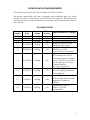
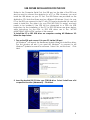
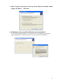


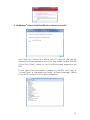
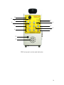
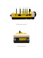

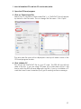
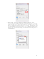


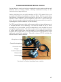

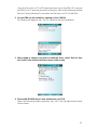

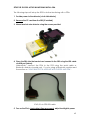

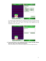
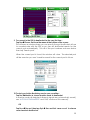
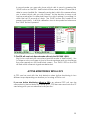


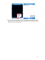
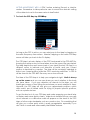


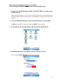
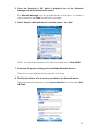

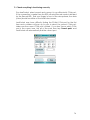


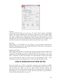

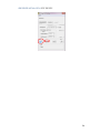

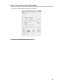
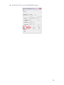


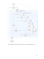
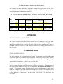

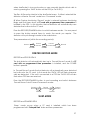


![Roostloggers [Titley] - An Introductory Manual](http://vs1.manualzilla.com/store/data/005649014_1-8c618e497bb2550a491bca85d50a292e-150x150.png)