1
HC900 Hybrid Controller
Installation and User Guide
Industrial Measurement and Control
Doc. No.:
51-52-25-107
Revision:
5
Date:
9/03
Notices and Trademarks
Copyright 2003 by Honeywell
Revision 5 Sept. 2003
Warranty/Remedy
Honeywell warrants goods of its manufacture as being free of defective materials and faulty workmanship. Contact
your local sales office for warranty information. If warranted goods are returned to Honeywell during the period of
coverage, Honeywell will repair or replace without charge those items it finds defective. The foregoing is Buyer's sole
remedy and is in lieu of all other warranties, expressed or implied, including those of merchantability and
fitness for a particular purpose. Specifications may change without notice. The information we supply is believed
to be accurate and reliable as of this printing. However, we assume no responsibility for its use.
While we provide application assistance personally, through our literature and the Honeywell web site, it is up to the
customer to determine the suitability of the product in the application.
Industrial Measurement and Control
Honeywell
1100 Virginia Drive
Fort Washington, PA 19034
Honeywell is a U.S. registered trademark of Honeywell
Other brand or product names are trademarks of their respective owners.
ii
HC900 Hybrid Controller Installation and User Guide
Revision 5
9/03
About This Document
Abstract
This document provides descriptions and procedures for the installation, operation and maintenance of the HC900
Hybrid Controller hardware.
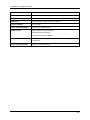
References
The following list identifies all documents that may be sources of reference for material discussed in this
publication.
Document Title
ID #
HC900 Hybrid Controller Technical Overview Specification
51-52-03-31
HC900 Hybrid Controller Operator Interface User Guide
51-52-25-108
HC900 Hybrid Control Designer User Guide
51-52-25-110
HC900 Hybrid Controller Function Block Reference Guide
51-52-25-109
HC900 Hybrid Controller Communications User Guide
51-52-25-111
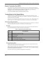
Contacts
World Wide Web
The following lists Honeywell’s World Wide Web sites that will be of interest to our customers.
Honeywell Organization
WWW Address (URL)
Corporate
http://www.honeywell.com
Industrial Measurement and Control
http://www.honeywell.com/imc
Telephone
Contact us by telephone at the numbers listed below.
Organization
United States and Canada
Honeywell
Phone Number
1-800-423-9883
1-888-423-9883
1-800-525-7439
Revision 5
9/03
HC900 Hybrid Controller Installation and User Guide
Tech. Support
Q&A Faxback
(TACFAQS)
Service
iii
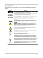
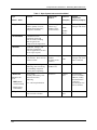
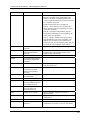
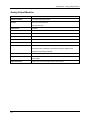
Symbol Definitions
The following table lists those symbols that may be used in this document and on the product to denote certain
conditions.
Symbol
Definition
This DANGER symbol indicates an imminently hazardous situation, which,
if not avoided, will result in death or serious injury.
This WARNING symbol indicates a potentially hazardous situation, which, if
not avoided, could result in death or serious injury.
This CAUTION symbol may be present on Control Product instrumentation
and literature. If present on a product, the user must consult the
appropriate part of the accompanying product literature for more
information.
This CAUTION symbol indicates a potentially hazardous situation, which, if
not avoided, may result in property damage.
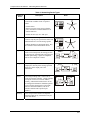
WARNING
PERSONAL INJURY: Risk of electrical shock. This symbol warns the user of a
potential shock hazard where HAZARDOUS LIVE voltages greater than 30 Vrms,
42.4 Vpeak, or 60 Vdc may be accessible. Failure to comply with these
instructions could result in death or serious injury.
ATTENTION, Electrostatic Discharge (ESD) hazards. Observe precautions for
handling electrostatic sensitive devices
CAUTION, HOT SURFACE: This symbol warns the user of potential hot surfaces
which should be handled with appropriate caution.
Protective Earth (PE) terminal. Provided for connection of the protective earth
(green or green/yellow) supply system conductor.
Functional earth terminal. Used for non-safety purposes such as noise immunity
improvement. NOTE: This connection shall be bonded to protective earth at the
source of supply in accordance with national and local electrical code requirements.
Earth Ground. Functional earth connection. NOTE: This connection shall be bonded
to Protective earth at the source of supply in accordance with national and local
electrical code requirements.
Chassis Ground. Identifies a connection to the chassis or frame of the equipment
shall be bonded to Protective Earth at the source of supply in accordance with
national and local electrical code requirements.
iv
HC900 Hybrid Controller Installation and User Guide
Revision 5
9/03
Contents
Introduction ............................................................................................. 1
Purpose ........................................................................................................................1
Functional Description ..................................................................................................2
Functional Description ..................................................................................................2
Feature Summary.........................................................................................................3
Components and Architecture................................................................. 5
Overview.......................................................................................................................5
Components .................................................................................................................5
Hardware Components.................................................................................................8
Ethernet Devices/Considerations ...............................................................................13
Serial Ports (RS232 and RS485) ...............................................................................19
Networking Basics Reference ....................................................................................22
Pre-Installation Planning ....................................................................... 36
Overview.....................................................................................................................36
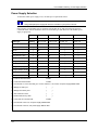
Power Supply Selection..............................................................................................37
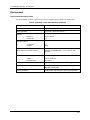
Environment ...............................................................................................................38
Orientation of Rack Mounting.....................................................................................39
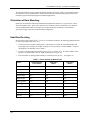
Heat Rise De-rating ....................................................................................................39
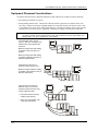
Equipment Placement Considerations .......................................................................41
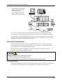
Electrical Considerations ............................................................................................42
Installation Guide .................................................................................. 49
Overview.....................................................................................................................49
I/O Module Installation and Wiring ........................................................ 57
Overview.....................................................................................................................57
Module Placement in Racks.......................................................................................57
Remote Termination Panel (RTP) ..............................................................................59
Terminal Block-to-Field (Signal) Wiring......................................................................59
Removal and Insertion Under Power (RIUP) .............................................................62
I/O Installation Procedures .........................................................................................63
I/O Terminal Block Wiring Diagrams ..........................................................................68
Revision 5
9/03
HC900 Hybrid Controller Installation and User Guide
v
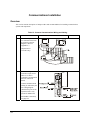
Communications Installation ................................................................. 85
Overview.....................................................................................................................85
Connecting the HC900 Controller to a PC with the Hybrid Control Designer Software88
RS-485 Link to Operator Interface ...........................................................................100
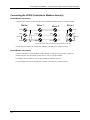
Connecting the HC900 Controller to Modbus device(s)...........................................105
Operating Characteristics.................................................................... 107
Introduction...............................................................................................................107
Overview...................................................................................................................107
Power Down / Power Up ..........................................................................................107
Controller Modes ......................................................................................................110
Software Download/Upload Functions .....................................................................114
Diagnostics and Troubleshooting ........................................................ 117
Overview...................................................................................................................117
External Indications of Diagnostic Information .........................................................117
User Interface ...........................................................................................................121
Analog Calibration ............................................................................... 140
Overview...................................................................................................................140
Removal and Replacement Procedures.............................................. 145
Overview...................................................................................................................145
Safety Considerations - PLAN AHEAD! ...................................................................145
Controller Components and modules .................................................. 155
Specifications ...................................................................................... 156
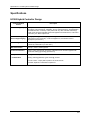
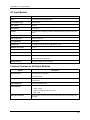
HC900 Hybrid Controller Design ..............................................................................156
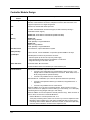
Controller Module Design .........................................................................................157
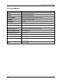
Scanner Module Design ...........................................................................................158
Rack Design .............................................................................................................159
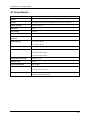
Input Output System: Common Features.................................................................160
Analog Input, Analog Output Modules: Common Features......................................161
Analog Input Module.................................................................................................161
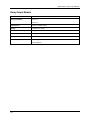
Analog Output Modules ............................................................................................163
Digital Input Modules; Common Features ................................................................164
Contact Input Module ...............................................................................................164
vi
HC900 Hybrid Controller Installation and User Guide
Revision 5
9/03
DC Input Module.......................................................................................................165
AC Input Module.......................................................................................................166
Features Common to all Output Modules.................................................................166
DC Output Module....................................................................................................167
AC Output Module ....................................................................................................168
Relay Output Module................................................................................................169
Environmental and Operating Conditions.................................................................170
Appendix A Site Planning Documentation Aids................................... 176
Overview...................................................................................................................176
I/O Module Configurator ...........................................................................................180
I/O Module Channel Assignment Configurator.........................................................181
Peer Network Configurator.......................................................................................182
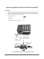
Appendix B Installation of Remote Termination Panels (RTPs) ................. 183
Overview...................................................................................................................183
Analog Input .............................................................................................................184
Relay Output.............................................................................................................191
Digital Input/Digital Output/Analog Output................................................................194
RTP Cable wire positions and colors .......................................................................204
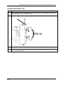
Latch/Unlatch RTP to rail..........................................................................................205
Index
Sales and Service
Declaration of CE Conformity
Revision 5
9/03
HC900 Hybrid Controller Installation and User Guide
vii
Tables
Table 1 – Descriptions of Major Components (Figure 3)..............................................................................................7
Table 2 Simultaneous serial port configurations .........................................................................................................19
Table 3 - Open System Interconnection Model ...........................................................................................................25
Table 4 - Networking Device Types............................................................................................................................26
Table 5- Glossary of Networking Terms .....................................................................................................................27
Table 6 - Operating Limits and Installation Guidelines...............................................................................................38
Table 7 - Power Applied, by Module Type .................................................................................................................39
Table 8 - Guidelines for Grouping Wires ....................................................................................................................44
Table 9 - Installation Tools..........................................................................................................................................49
Table 10 - Site and Equipment Preparation .................................................................................................................50
Table 11 - Install HC900 Controller Components.......................................................................................................52
Table 12 - Minimum Recommended Wire Sizes.........................................................................................................59
Table 13 - RIUP: Potential Hazards and Recommended Actions................................................................................62
Table 14 - Connect Input/Output Wiring.....................................................................................................................63
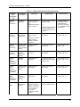
Table 15 - Connect Communications Wiring and Cabling..........................................................................................85
Table 16 - Links to Controller Communication Ports..................................................................................................86
Table 17 - PC Cable Pinouts........................................................................................................................................90
Table 18 - Parts needed for RS-485 Cabling .............................................................................................................100
Table 19 - Controller Operating Modes.....................................................................................................................111
Table 20 - Mode Switch Functions............................................................................................................................112
Table 21 - Controller Behavior in Mode Transition ..................................................................................................113
Table 22 - Configuration file downloading ...............................................................................................................115
Table 23 - LED Indications on Main CPU ................................................................................................................119
Table 24 - LED Indications on Scanner Module .......................................................................................................120
Table 25 - LED Indications on I/O Module...............................................................................................................120
Table 26 - LED Indications on Ethernet Hub ............................................................................................................121
Table 27 - Controller Module Diagnostics ................................................................................................................121
Table 28 - Bad Module Diagnostics ..........................................................................................................................133
Table 29 - Bad Channel Diagnostics .........................................................................................................................134
Table 30 - Scanner Diagnostics .................................................................................................................................135
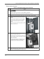
Table 31 - Power Supply Replacement......................................................................................................................146
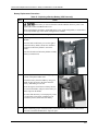
Table 32 - Controller Module Replacement ..............................................................................................................148
Table 33 - Scanner Module Replacement..................................................................................................................149
Table 34 - RIUP: Potential Hazards and Recommended Actions..............................................................................150
Table 35 - I/O Module Replacement .........................................................................................................................151
Table 36 - Installing Backup Battery (CPU not initialized).......................................................................................153
Table 37 - Replacing a Backup Battery (CPU Powered)) .........................................................................................154
Table 38 - HC900 PV Input Types and Ranges.........................................................................................................171
viii
HC900 Hybrid Controller Installation and User Guide
Revision 5
9/03
Figures
Figure 1 – Small HC900 Controller Configuration ......................................................................................................2
Figure 2 – Expanded HC900 Controller Configuration (C50 CPU only)......................................................................2
Figure 3 - Configuration with Multiple Controllers ......................................................................................................6
Figure 4 - Controller Rack Components........................................................................................................................8
Figure 5 - I/O Expander Rack Components (C50 CPU only)........................................................................................8
Figure 6 - Rack Options.................................................................................................................................................9
Figure 7 – Power Supply ...............................................................................................................................................9
Figure 8 - Controller Module.......................................................................................................................................10
Figure 9 - Scanner Module ..........................................................................................................................................10
Figure 10 - I/O Module Terminal Blocks ....................................................................................................................11
Figure 11 - RS232 Modem Devices ............................................................................................................................12
Figure 12 – HC900 Controller Configurations ............................................................................................................13
Figure 13 - Modular Network Structure ......................................................................................................................15
Figure 14 - Modbus/TCP Framing ..............................................................................................................................16
Figure 15 - Typical installation using a Cable Modem................................................................................................18
Figure 16 Serial Port Configurations 1 - 6...................................................................................................................20
Figure 17 Serial Port Configurations 7 – 11 ................................................................................................................21
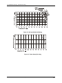
Figure 18 - AC Input Module de-Rating .....................................................................................................................40
Figure 19 - Power Supply De-rating............................................................................................................................40
Figure 20 - Cabinet Wiring, Single Chassis.................................................................................................................43
Figure 21 - Cabinet Wiring, Multiple Chassis .............................................................................................................43
Figure 22 - Master Control Relay Wiring Example.....................................................................................................46
Figure 23 - Rack Dimensions ......................................................................................................................................47
Figure 24 - Vertical Spacing of Racks.........................................................................................................................47
Figure 25 - I/O Module Installation.............................................................................................................................57
Figure 26 - Terminal Block Styles...............................................................................................................................58
Figure 27 - Signal-Wire Grounding.............................................................................................................................60
Figure 28 - Wire-Shield Grounding.............................................................................................................................60
Figure 29 - Terminal Block Jumper Installation..........................................................................................................61
Figure 30 - RTD Inputs ...............................................................................................................................................68
Figure 31 - Universal Analog Input Wiring Diagram..................................................................................................69
Figure 32 - Examples of RTD Input Wiring................................................................................................................69
Figure 33 - Analog Input Wiring - Eight TCs..............................................................................................................70
Figure 34 - Analog Input Wiring - Eight Resistance Inputs ........................................................................................70
Figure 35 - Analog Input Wiring - Eight RTDs...........................................................................................................71
Figure 36 Analog Input Wiring – Slidewire (Position Proportion Block) ...................................................................71
Figure 37 - Analog Output Wiring Diagram................................................................................................................72
Figure 38 - DC Input Module Wiring Diagram ...........................................................................................................73
Figure 39 - DC Input Module Jumper .........................................................................................................................74
Figure 40 - AC Input Module Wiring Diagram ...........................................................................................................75
Figure 41 - AC Input Module Jumper .........................................................................................................................76
Figure 42 - Contact Input Wiring Diagram .................................................................................................................77
Figure 43 - DC Output Module Wiring Diagram ........................................................................................................79
Figure 44 - DC Output Jumpers...................................................................................................................................79
Figure 45 - AC Output Module Wiring Diagram ........................................................................................................81
Figure 46 - AC Output Module Jumper.......................................................................................................................81
Figure 47 - Schematic Example: Relay Output and External Wiring ..........................................................................82
Figure 48 - Relay Output Module Wiring Diagram.....................................................................................................83
Figure 49 - Relay Output Module Jumpers .................................................................................................................84
Figure 50 - Null Modem Cable Construction ..............................................................................................................90
Figure 51 - RS-232 Remote Access via Modems ........................................................................................................91
Figure 52 - Warm Start Operation .............................................................................................................................108
Figure 53 - Cold Start Operation ...............................................................................................................................109
Revision 5
9/03
HC900 Hybrid Controller Installation and User Guide
ix
Figure 54 - Pathways for Upload/Download Transactions........................................................................................114
Figure 55 - LED Indicators........................................................................................................................................118
Figure 56 - Terminal Board Connections for AI Calibration.....................................................................................142
Figure 57 - Terminal board Connections for AO Calibration....................................................................................143
Figure 58 - Example Site Map - Equipment Placement.............................................................................................177
Figure 59 - Example Network System Diagram........................................................................................................178
Figure 60 Example installation..................................................................................................................................183
Figure 61 Analog input terminal and DIP switch designations .................................................................................186
Figure 62 Two–wire transmitter connections with common 24 VDC supply ...........................................................186
Figure 63 Milliamp input connections with 250 ohm shunt resistance ....................................................................187
Figure 64 Volt, millivolt input connections..............................................................................................................187
Figure 65 Three-wire RTD input connections ..........................................................................................................188
Figure 66 Two-wire RTD or ohm input connections................................................................................................188
Figure 67 Slidewire feedback connections for actuators ..........................................................................................189
x
HC900 Hybrid Controller Installation and User Guide
Revision 5
9/03
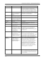
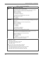
Introduction
Purpose
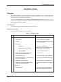
This publication describes the Honeywell HC900 Hybrid Controller, and facilitates its installation,
operation, and maintenance. This publication includes the following sections.
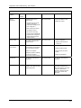
Section Title
Section Content
Introduction
Describes the content and purpose of this manual relative to other manuals for the
HC900 Hybrid Controller.
System Overview
Functional features and physical characteristics of the system and of each major
component of the HC900 Hybrid Controller. This section includes background
information on Ethernet networking components and methods of interconnection.
Pre-Installation Planning
Includes pre-planning considerations, environmental operating limits, and
procedural guidelines for planning an installation.
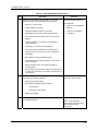
Installation Guide
Procedures for installing the major components of the system: controller rack, I/O
expansion racks (C50 CPU only), and communication interconnections.
Input/Output Installation
and Wiring
Procedures for installing I/O modules in the controller rack and I/O expansion
racks (C50 CPU only), and for wiring field devices to the terminal block
associated with each I/O module.
Communications
Installation
Provides guidelines for installing RS-232, RS-485, and Ethernet cabling and
associated components.
Controller Operating
Characteristics
Characteristics of the HC900 Hybrid Controller as they relate to configuration of a
control strategy, and to operation of an installed and running system.
Diagnostics and
Troubleshooting
Descriptions of the mechanisms that detect and react to faults in the operation of
HC900 Hybrid Controller hardware and/or software components.
Analog Calibration
Describes hardware configuration required for calibrating AI and AI modules from
the configuration software.
Removal and
Replacement Procedures
Provides guidelines for replacing system components; includes Cautions and
Warnings as applicable.
Specifications
Tables that provide details of HC900 Hybrid Controller design and functioning.
Index
Alphabetical listing, with page references, of terms, components, and topics
included in this manual.
Revision 5
9/03
HC900 Hybrid Controller Installation and User Guide
1
Introduction - Functional Description
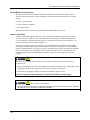
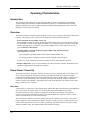
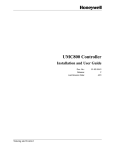
Functional Description
The Honeywell HC900 Hybrid Controller is an
integrated loop and logic controller that is designed
specifically for small- and medium-scale unit operations
It comprises a set of hardware and software modules that
can be assembled to satisfy any of a broad range of
process control applications. The HC900 Hybrid
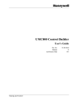
Controller can consist of a single rack, as indicated in
Figure 1, or can be can be networked with other
controllers via Ethernet links to expand the dimensions
of control over a wider range of unit processes, as
indicated in Figure 2.
Figure 1 – Small HC900 Controller Configuration
Figure 2 – Expanded HC900 Controller Configuration (C50 CPU only)
2
HC900 Hybrid Controller Installation and User Guide
Revision 5
9/03
Introduction - Feature Summary
The HC900 Controller design enables users and OEMs who are adept in system integration to assemble a
system that fits a broad range of requirements. Any configuration can be readily modified or expanded as
requirements dictate. In initial configuration and in subsequent modifications, the HC900 Controller
affords an optimum balance of performance and economy.
Configurations such as those shown in Figure 1 and in Figure 2, as well as many variations, can be
assembled from modular components. Many of the components are available from Honeywell, and some
are available from third-party suppliers. These modular components are available in any quantity and mix
that make the most sense for a given application.
As indicated in Figure 2, the HC900 Controller includes provisions for communication via Ethernet with
host systems such as the Honeywell PlantScape HMI and other HMI software that supports Ethernet
Modbus/TCP protocol. Also, the communication structure of the HC900 Controller enables remote
placement of input/output components, allowing significant economies in cabling and wiring.
Feature Summary
Hardware
•
Modular rack structure; components are ordered individually as needed
•
CPU embodies Ethernet connectivity
•
Easy to assemble, modify, and expand
•
Local(C30,C50) and Remote input/output racks(C50 only), private Ethernet-linked in sub network
•
Parallel processing - a CPU in each I/O module performs signal processing, to preserve update rates
Communications
•
RS-232 Link to PC configuration tool (up to 50 feet or 12.7 meters) or modem. Port configurable as
Modbus RTU/TCP master or slave
•
RS-485 2-wire link to the Operator Interface (up to 2000 feet or 601meters). Port configurable as
Modbus RTU/TCP master or slave
•
Ethernet 10BaseT connection to: up to 5 PC hosts via Modbus/TCP protocol, Peer-to Peer
communication with other HC900 Controllers, and the Internet
•
Private Ethernet 10BaseT connection to I/O expansion racks (C50 CPU only)
Revision 5
9/03
HC900 Hybrid Controller Installation and User Guide
3
Introduction - Feature Summary
Control Functions
•
•
Comprehensive set of Function Blocks; includes:
−
PID:
Model C50 - up to 32 loops
Model C30 – up to 8 loops
−
Setpoint Programmers: up to 8; SP Profiles: pool of 99, with up to 50 Segments/Profile; SP
Schedulers: 1 or 2; Setpoint Schedules: up to 20, with up to 50 Segments/Schedule
−
Sequencers: up to 4; Sequences: up to 20; Steps per Sequence: up to 64
−
Recipes: up to 50; up to 50 parameters per recipe;
−
Logic, Fast Logic
−
Counters/Timers
−
Math, Calculations
−
Signal Selector
−
Auxiliary
−
Communications
Up to 400 (Model C30) or 2000 (Model C50) user-configured blocks per control strategy
Input/Output
•
AI:
Model C30 - Up to 96 analog inputs; 0.1% of span accuracy
Model C50 - Up to 256 analog inputs; 0.1% of span accuracy
•
AO:
Model C30 - Up to 48 analog outputs
Model C50 - Up to 64 analog outputs
•
Up to 512 inputs and outputs (192 for Model C30) (combined local and remote, analog and digital)
•
Analog Module Types:
•
•
−
Universal Analog Input - 8 point
−
Analog Output - 4 point
Digital Input Module Types:
−
120/240Vac & 24Vdc Input - 16 point
−
Contact Input - 16 point
Digital Output Module Types:
−
120/240Vac Output - 8 point
−
24Vdc Output - 16 point
−
Relay Output - 8 point
Alarms/Events
Up to 240 Alarms (20 groups of 12)
Up to 64 Events
E-Mail notification of Alarms and Events to up to three addresses per controller, by alarm priority (1-5)
4
HC900 Hybrid Controller Installation and User Guide
Revision 5
9/03
Components and Architecture
Overview
This section provides a description of each of the major components that can be included in an HC900
Controller physical configuration, and indicates some of the methods by which they can be combined.
Components
The Honeywell HC900 Hybrid Controller includes a set of hardware modules that can be combined and
configured as required for a wide range of small to medium process control applications.
Some of the modules are required in all configurations. Others are optional; they are selected as
appropriate to provide optional functions and/or to "size" the system, either in initial planning, or in
modifying and/or expanding the system to meet changing requirements.
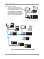
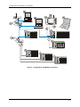
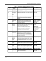
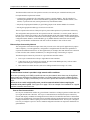
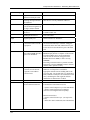
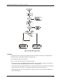
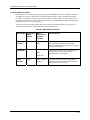
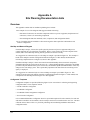
An HC900 Controller configuration with multiple controllers is illustrated in Figure 3. This illustration
includes key-numbers that identify components that are described in Table 1.
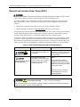
Communications lockout is possible in high network traffic conditions.
When inter-connecting your HC900 controller sub-net to a plant network where there may be significant
network traffic not directed to the HC900 controllers or to related supervisory control or data acquisition
software interfaces, we highly recommend you use a router to protect the controller from this extraneous
traffic.
Failure to do so could, in high traffic cases, result in communications lockout requiring the
controller to be power-cycled. See Figure 59 on page 178 for an example of an installation for a typical
interface to another network sub-net.
Revision 5
9/03
HC900 Hybrid Controller Installation and User Guide
5
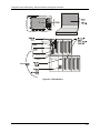
Components and Architecture - Components
Figure 3 - Configuration with Multiple Controllers
6
HC900 Hybrid Controller Installation and User Guide
Revision 5
9/03
Components and Architecture - Components
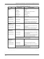
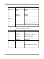
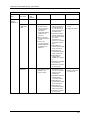
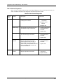
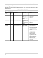
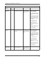
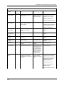
Table 1 – Descriptions of Major Components (Figure 3)
Key No.
Component
Name
Description
1
Controller
(Local) Rack
Includes: Rack, Power Supply, Controller Module,
and I/O modules
Honeywell
2
I/O Expansion
Rack
(C50 CPU
only)
(Optional) Includes: Rack, Power Supply, Scanner
Module, and I/O modules
Honeywell
3
Operator
Interface
(Optional) link to RS-485 port on a Controller
Module; provides operating and utilities displays.
Includes buttons and (optional) AT-keyboard
interface.
Honeywell
4
PC
Configuration
Tool
(Optional) PC (laptop or desktop) connects to
RS-232 port on any (one) Controller module.
Includes Honeywell Hybrid Control Designer
(configuration software).
PC is from third-party
supplier. Configuration
software is from
Honeywell.
5
HMI (HumanMachine
Interface)
(Optional) PC link to Ethernet network, which may
include other HMIs, other HC900 Controllers, and
other networks (including Internet).
PC is from third-party
supplier.
Typically includes HMI operating software.
May also include Hybrid Control Designer
(configuration tool and utility software).
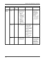
Revision 5
9/03
Source
HMI software is
available from
Honeywell (PlantScape
or SpecView32) or
from third-party
supplier.
6
Ethernet
10BaseT Hub
Enables connection of the private Ethernet
10BaseT port on a Controller Module to the
Scanner modules on 2, 3, or 4 I/O Expansion
racks. (C50 CPU only) (If a single I/O expansion
rack is connected directly to a Controller Module,
the Hub is not required.)
Honeywell
6a
Ethernet
10BaseT
Switch or
Router
Enables inter-connection of several 10BaseT
Ethernet devices in an Ethernet network. Devices
include other HC900 Controllers, HMIs, and can
also include routers, brouters, servers, and other
devices in wider networks.
Third-party suppliers.
7
Ethernet
CAT5E
shielded cable
Connects I/O expansion racks (C50 CPU only) to
controllers and/or to 10baseT Ethernet hubs. 10’or
20’ (3.04 or 6.08m)
Third-party suppliers or
Honeywell
8
Ethernet
CAT5E
shielded cable
Connects devices in Ethernet Open Connectivity
network. Cross-over cable is used for Controllerto-PC connection; straight-through for Controller-toHub connection. 20’ (6.08m).
Third-party suppliers or
Honeywell
9
RS-485 cable
Belden #9271 or equivalent, up to 2000’ (601m).
Third-party suppliers
10
RS-232 cable
Null modem cable, up to 50’ (15.24m) (PC modem
cable if used with Modems.)
Third-party suppliers or
Honeywell
HC900 Hybrid Controller Installation and User Guide
7
Components and Architecture - Hardware Components
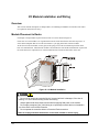
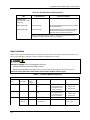
Hardware Components
This section contains general descriptions of each of the major components of the HC900 system. For
environmental specifications, refer to the section on Pre-Installation Planning.
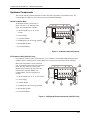
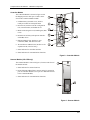
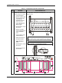
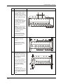
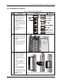
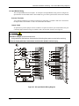
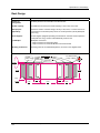
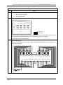
HC900 Controller Rack
An HC900 Controller ("local rack") is
shown in Figure 4. As indicated in this
figure, the Controller Rack includes:
1. a Rack, available in 4- 8-, or 12-slot
versions
2. a Power Supply
3. a Controller Module
4. Grounding bars (for I/O wiring; optional)
5. Input/Output modules.
6. I/O Terminal Blocks
Figure 4 - Controller Rack Components
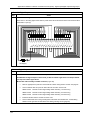
I/O Expansion Rack (C50 CPU only)
I/O expansion ("remote") racks, shown in Figure 5, are available to accommodate additional input/output
modules, and/or to enable location of I/O modules close to the process and remote from the controller.
Most of the components in an I/O expansion
rack are identical to those used in the Controller
Rack. The only difference is the Scanner
Module (item 3) that occupies the same rack
location as the Controller Module in a
Controller Rack. An I/O expansion rack
includes:
1. a Rack, available in 4- 8-, or 12-slot versions
2. a Power Supply
3. a Scanner Module
4. Grounding bars (for I/O wiring; optional)
5. Input/Output modules
6. I/O Terminal Blocks
Figure 5 - I/O Expander Rack Components (C50 CPU only)
8
HC900 Hybrid Controller Installation and User Guide
Revision 5
9/03
Components and Architecture - Hardware Components
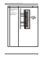
Rack Options
Racks are available in 4-slot, 8-slot, and 12-Slot
versions. Racks are interchangeable between the
Controller rack and an IO expansion rack (C50
CPU only), and all three versions shown in Figure
6 are available for either purpose.
Figure 6 - Rack Options
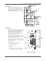
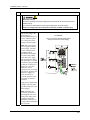
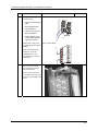
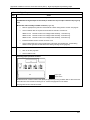
Power Supply
The P01 Power Supply, shown in Figure 7, provides
5 Vdc and 24 Vdc to the backplane connectors in the
local and remote racks. The Power Supply is
identical for the Controller Rack and for I/O
expansion racks(C50 CPU only), and for all rack
versions (4-slot, 8-slot, and 12-Slot).
The less expensive lower capacity P02 power supply
is available for reduced I/O applications. See page
37 to determine correct power supply.
Each power supply includes an internal 5.0-amp fuse
that is not field-replaceable. (An external fuse may
be added by the user.)
Items shown with key numbers:
1. Voltage test points (P01model only)
2. AC Input terminal block
3. Wiring label
4. Grounding lug (Reference; lug is not part of
Power Supply; it is staked to bottom of Rack.)
Figure 7 – Power Supply
Revision 5
9/03
HC900 Hybrid Controller Installation and User Guide
9
Components and Architecture - Hardware Components
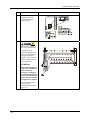
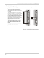
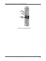
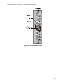
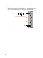
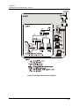
Controller Module
The Controller Module is shown in Figure 8 with
the hinged protective door open. Features at the
front of the Controller Module include:
1 - a lithium battery (beneath cover), which is
readily accessible for field replacement.
2 - RS-232 Port; interface to the PC configuration
tool, external modem, or Modbus device
3 - Mode switch (Program Lock, Run/Program, Run
Lock)
4 - RS-485 Port for Honeywell Operator Interface
or Modbus device
5 - Ethernet 10BaseT Port; interface to peer
controllers, HMIs, and other networks
6 – Private Ethernet 10BaseT Port; interface to I/O
expansion racks (C50 CPU only)
7 - Status indicator for controller functions
8 - Status indicators for communications functions
Figure 8 - Controller Module
Scanner Module (C50 CPU only)
The Scanner Module is shown in Figure 9; features at the front of
the module include:
1 - Status indicator for scanner functions.
2 - Private Ethernet 10BaseT Port; connects to the I/O expansion
port on Controller Module (or to a port on a Hub that connects
to the Controller Module)
3 - Status indicators for communications functions
Figure 9 - Scanner Module
10
HC900 Hybrid Controller Installation and User Guide
Revision 5
9/03
Components and Architecture - Hardware Components
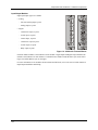
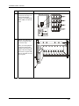
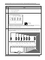
Input/Output Modules
Eight input/output types are available:
•
•
Analog
−
Universal Analog Input, 8-point
−
Analog Output, 4-point
Digital
−
120/240 Vac input, 16-point
−
24 Vdc input, 16-point
−
Contact input, 16-point
−
120/240 Vac output, 8-point
−
24 Vdc output, 16-point
−
Relay output, 8-point
Figure 10 - I/O Module Terminal Blocks
Each I/O module includes a status indicator for the module. Digital Input and Digital Output modules also
include a status indicator for each channel. Terminal blocks available include the Euro style (on the left in
Figure 10) and the Barrier style (on the right).
For more information on I/O modules and associated terminal blocks, refer to the section in this manual on
Input/Output Installation and Wiring.
Revision 5
9/03
HC900 Hybrid Controller Installation and User Guide
11
Components and Architecture - Hardware Components
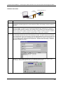
Personal Computer
A Personal Computer is required for creating the control and data acquisition strategy (configuration file)
that runs in the controller, using the Hybrid Control Designer configuration software. The PC can also be
used to download/upload configuration files to/from the controller, and can be used to download program
updates to firmware in the Controller Module and/or Scanner Modules.
A PC can be connected to the controller via the RS-232 Port on the Controller module, and can also be
networked to the controller via the Ethernet 10BaseT Open Connectivity Network port.
NOTE: For specific PC requirements and for specific software requirements, refer to the Hybrid Control
Designer Users Manual.
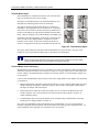
RS-232 Modem Devices
The PC configuration tool
connects from the RS-232
connector on the upper part
of the Controller Module to a
serial port on the PC. The PC
can be located remote from
the Controller by using
Modems and telephone links.
Modems and suitable cabling
are available from third-party
vendors.
Figure 11 - RS232 Modem Devices
12
HC900 Hybrid Controller Installation and User Guide
Revision 5
9/03
Components and Architecture - Ethernet Devices/Considerations
Ethernet Devices/Considerations
Ethernet device requirements vary with specific applications. Regarding intended use, however, they fall
into two categories:
• Components of the Ethernet Open Connectivity Network, which links an HC900 Hybrid Controller to
Peers, to HMI Supervisory Stations, and to other Ethernet 10Base-T devices that support TCP/IP.
• Components of the I/O expansion network(C50 CPU only), which is an independent, private network
that is designed to work exclusively with the HC950 expansion racks.
Installation of the I/O expansion network is relatively straightforward; it includes only a few devices and
requires only configuration of jumpers in Scanner modules.
The Ethernet Open connectivity Network is potentially more complex than the I/O expansion network, and
in some cases, may require the services of an IT networking professional.
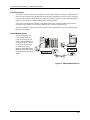
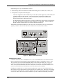
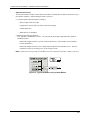
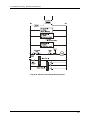
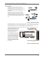
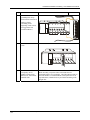
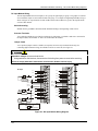
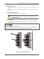
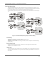
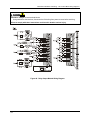
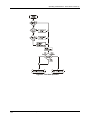
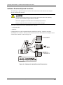
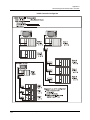
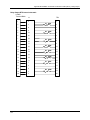
I/O Expansion Network(C50 CPU only)
Examples of HC900 Controller I/O expansion configurations are shown in Figure 12.
Crossover Cable
Straight Cable
Figure 12 – HC900 Controller Configurations
In Figure 12, any of the racks shown in each controller configuration can be 4-, 8-, or 12-slot versions.
Note that in configuration 2 (C50 CPU only), the Ethernet cable connects directly from the 10BaseT
connector on the Controller Module directly to the Scanner Module on the single I/O expansion rack. In
configuration 3 (C50 CPU only), the Ethernet cable goes from the 10BaseT port on the Controller Module
using a crossover cable to the Hub, and a straight through cable from each of the Hub ports to the 10BaseT
port on the Scanner Modules.
The Ethernet cabling for the I/O expansion links (C50 CPU only) are standard shielded Cat 5E cabling,
with standard RJ45 connectors. Each cable segment can be up to 100 meters (328 feet) long. Note that in
configuration 3, a second Hub is used in-line with the I/O expansion rack shown on the bottom of the
illustration, so as to extend the distance (up to an additional 100 meters) to the remote rack. The total
number of hubs allowed is limited to two in series between the controller and scanners. One combination
of two in series is illustrated.
Revision 5
9/03
HC900 Hybrid Controller Installation and User Guide
13
Components and Architecture - Ethernet Devices/Considerations
The Ethernet Hubs used in the I/O expansion network (C50 CPU only)are available from Honeywell.
I/O implementation requirements include:
•
Constructing a configuration file, and loading it into the Controller Module. This file includes I/O
numbering assignments for each I/O Function Block regarding Rack Number, Module Number ("slot"
number, or position in the rack, starting from the left), and Channel Number.
•
Physically assigning Rack Numbers, by positioning jumpers in the Scanner Module for each rack.
•
Placing the appropriate module type in each slot in each rack.
The I/O expansion network uses Honeywell private protocol that optimizes I/O performance and security.
The configuration and operation of the I/O expansion network is automatic, it is entirely under control of
built-in private software that resides in the Controller Module and in each Scanner Module included in the
HC900 system. The controller examines the control strategy stored in its memory, verifies that the physical
configuration (Rack Numbers, and I/O Module type- by Module Number) matches the stored control
strategy, and establishes communication with each of the I/O modules in each of the I/O racks.
Ethernet Open Connectivity Network
The configuration of the Ethernet Open Connectivity Network varies with specific applications in purpose
and in complexity. In some applications, configuration is straightforward and within the capabilities of
experienced installation technicians. In other applications (for example, those that include inter-connection
to other networks such as Intranet and Internet), a working knowledge of networking is required.
The Ethernet Open Connectivity Network for a given HC900 Controller enables:
•
Peer-to-peer communication with up to eight other HC900 Controllers
•
Connection to up to five PC hosts (for example, PCs that include HMI supervisory software and/or
Hybrid Control Designer configuration software)
•
Inter-connection to other networks (such as for sending Alarm/Event messages via e-mail.)
Communications lockout is possible in high network traffic conditions.
When inter-connecting your HC900 controller sub-net to a plant network where there may be significant
network traffic not directed to the HC900 controllers or to related supervisory control or data acquisition
software interfaces, we highly recommend you use a router to protect the controller from this extraneous
traffic.
Failure to do so could, in high traffic cases, result in communications lockout requiring the
controller to be power-cycled. See Figure 59 on page 178 for an example of an installation for a typical
interface to another network sub-net.
Peer-to-Peer Communication
Peer-to-peer communication enables any given HC900 Controller to exchange signal and variable data with
up to eight other HC900 Controllers. Peer-to-peer communication uses the Ethernet Open Connectivity
network and employs standard User Datagram Protocol (UDP) for fast and efficient transfer of information.
Peer-to-peer communication is based on fail-safe and data expiration mechanisms that provide for fault and
loading considerations without requiring reserved network bandwidth allocation. Peer-to-peer is designed
to be easy to configure as part of a device's standard configuration and does not require the distribution of a
global database.
14
HC900 Hybrid Controller Installation and User Guide
Revision 5
9/03
Components and Architecture - Ethernet Devices/Considerations
Implementing peer-to-peer communications involves:
• Interconnecting controllers with Ethernet media and networking devices (cables, hubs, switches, etc)
• Configuration (via Hybrid Control Designer):
−
Controller configuration, which includes entry of an IP address (and if applicable, a Subnet Mask) and
a Controller Name for each controller. (The Controller Name is used only by the Honeywell
proprietary software for network access between controllers; it should not be confused with a
Network Domain Name or Workgroup Name.)
−
Peer Data Exchange (PDE) function blocks, which are included in the control strategy (configuration
file). PDE function blocks include PDE Control, PDE Write, and PDE Read. (Refer to the HC900
Hybrid Controller Function Block User Guide for additional information.)
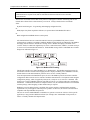
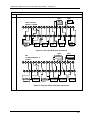
An illustration of HC900 Controller Peer-to-Peer on a Local Area Network (LAN) is given in Figure 13.
Typically, a Router is used for interconnection to another network (LAN, WAN, or other).
Figure 13 - Modular Network Structure
Connection to PC Hosts
Connection to PC hosts can be via Modbus/TCP as well as serial Modbus RTU over either the RS485 or
RS232 communications ports. Both ports support Modbus RTU and are configurable as master or slave.
The 5 TCP hosts can be concurrent with Modbus hosts on one or both of the other ports. Any given
controller is capable of concurrent communication with up to five PC hosts. (The meaning of the term
"host" varies, but for this definition, a PC host is any PC that is on the same LAN as the controller, or on
any LAN or WAN (Wide Area Network) that is network-connected to the controller.
Each HC900 Controller has five "sockets" (software and memory resources), each of which can service
data requests from any networked PC on a client (host)/server (controller) basis. The sockets are available
on a first-come, first-served basis. Typically, when the data service for any PC Host request is completed
or times out, it allows the socket to become available to any other PC Host in the hierarchy of networks.
Revision 5
9/03
HC900 Hybrid Controller Installation and User Guide
15
Components and Architecture - Ethernet Devices/Considerations
Note: PDE communications, discussed previously, do not use the PC host connection sockets. PDE
communications are separate from (and are transmitted concurrent with) PC host-to-controller
communications.
The PC host can include software that closely relates to and supports controller functioning and can also
include other software that is related remotely or not at all. Closely related software can include:
Either
Hybrid Control Designer - for generating and managing configuration files,
Or
HMI (Supervisory/Data Acquisition Software) or Operator Panel with Modbus/TCP driver
Or
Both configuration and HMI software (and or panel)
All communications between a controller and a PC host use Open Modbus/TCP protocol, whose
widespread use is making it an industry standard. Modbus/TCP is basically an adaptation of the Modbus
messaging structure that uses TCP/IP for a message carrier. Modbus messaging is available in two
versions: ASCII, in which each eight-bit byte is sent as 2 ASCII characters, and RTU, in which each byte
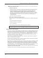
is sent as two four-bit hexadecimal characters. Each Modbus message frame is embedded into a TCP/IP
datagram as indicated in Figure 14.
Figure 14 - Modbus/TCP Framing
The HC900 Controller uses either Modbus/TCP or Modbus RTU. The Modbus mapping structure for
the HC900 Controller is based on the mapping structure employed in Honeywell’s UMC800 Controller,
and the function codes and methods for parameter access are also virtually identical.
From an implementation and installation aspect, the use of the Modbus protocol for HC900 Controller
configuration differs from the use for Controller-to-HMI communications. The Hybrid Control Designer
configuration package, which is supplied by Honeywell, is ready for use as soon as it is installed. This
package uses a subset of Modbus function codes that provide for very efficient and secure configuration
transactions. Communications details are transparent to the user; all communication drivers are included
with the package, and no mapping or other detailed setup is required.
HMI Supervisory/SCADA software is available from various suppliers, and functionality and setup
requirements vary with suppliers and with specific products. In all cases, the software selected must be
compatible with Open Modbus/TCP protocol.
The user can use the standard Modbus command set to generate a custom set of drivers for his specific
application, or may purchase additional software (for example, OPC with Modbus /TCP protocol) to
reduce or virtually eliminate development tasks.
16
HC900 Hybrid Controller Installation and User Guide
Revision 5
9/03
Components and Architecture - Ethernet Devices/Considerations
HMI software available for use with the HC900 Controller includes, but is not necessarily limited to the
packages whose descriptions follow.
•
•
available from Honeywell
−
PlantScape SCADA or Vista Software, which operates under Windows 2000 operating software,
provides PC-based supervisory control and data acquisition. This package includes a large
selection of standard operating display templates, which can reduce development time
significantly. PlantScape includes a full graphic display development environment, enabling
development of custom graphics that include animated responses to changing process conditions.
A batch reporting option is available in release 400, which includes a standard template for
creating batch reports.
−
SpecView32 (SpecView Corporation)
Other software (available from third-party sources)
The following software, which incorporates Modbus/TCP connectivity, is available from third-party
sources:
− The
Fix Family (Intellution Incorporated)
− Wonderware
− Citect
− OPC
(Wonderware Corporation)
(CI Technologies)
server/client software (various; available from Kepware and others)
Note: The items in this list are not sold by Honeywell. They have not all been tested and certified
by Honeywell, and are not necessarily recommended or endorsed by Honeywell for any specific use.
Inter-Connection to Other Networks
In many cases, an HC900 Controller application will include a single, free-standing controller that involves
no connections via the Ethernet Open Connectivity network. In other cases, the HC900 Controller will be a
member of a Local Area Network (LAN) as indicated in Figure 13. The HC900 controller LAN may be
very simple, or it may include many devices in a complex and very sophisticated structure. In any case, it
must always be regarded as a single, modular entity that can be protected from intrusion by any other
networking device to which this LAN is connected.
Various types of networking devices that enable selective connection to other networks are available. A
"Router" is commonly used for this purpose.
The feature that gives the Router its name is its ability to examine and "filter" message packets, permitting
passage of wanted messages and denying passage of all others.
Many Routers have a secondary, but important feature in that they enable translation of IP addresses, which
enables networks with dissimilar network IP addresses to communicate as though they were members of
the same network. This feature is particularly useful when an HC900 Controller LAN is installed under
"local addressing rules". That is, IP addressing can be assigned without approval of or conflict with world
Internet governing bodies. Later, when connecting to networks with more stringent addressing
requirements, it is necessary only to configure the Router with address mapping and connect it between the
existing LAN and the other existing network.
Connections to other networks vary in purposes and methods; some of these are described below.
Revision 5
9/03
HC900 Hybrid Controller Installation and User Guide
17
Components and Architecture - Ethernet Devices/Considerations
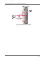
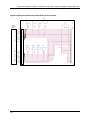
E-Mail Communications
The HC900 Controller includes e-mail software that enables communication of Alarms and Events to up to
three Internet addresses. Implementing this feature consists of:
• Using the Hybrid Control Designer to configure:
− Alarm Groups and Event Groups
− Assignment of specific alarms to priority and e-mail enabling
− E-Mail address lists
− SMTP mail server IP address
• Installing and configuring hardware
Note: This data is included for reference. The following items should be implemented by qualified
IT/MIS personnel.)
− Install and configure a Router to provide isolation and security. (This should be part of standard
network installation.)
− Install and configure internet access to Simple Mail Transport Protocol (SMTP) server. This may
include the location of an existing server on an existing network.
Note: Consult your service provider for availability of access to network, local cable, or DSL in your area.
Figure 15 - Typical installation using a Cable Modem
18
HC900 Hybrid Controller Installation and User Guide
Revision 5
9/03
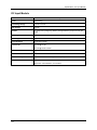
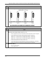
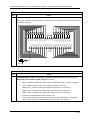
Components and Architecture - Serial Ports (RS232 and RS485)
Serial Ports (RS232 and RS485)
Overview
•
Ports configurable as ELN, Modbus RTU or Modbus TCP protocol.
•
Controller can act as Modbus master or slave through either port.
•
Controller can be master to slaves such as
•
−
Honeywell Operator Interface (1040, 559). Must be on 485 port. Will not work on 232 port with
232/485 converter.
−
Honeywell HC Designer PC software
−
Third party PC HMI software
−
Third party Operator Interface
Controller can slave to masters such as
−
Any Honeywell Modbus device (e.g., recorders, controllers, flame safety)
−
Any non-Honeywell Modbus device.
•
Only one master port at a time, can’t have RS232 and RS485 both as master ports.
•
For multiple slaves on RS232 port, a 232-to-485 converter is required.
•
Baud rates to 57,600
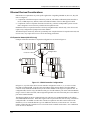
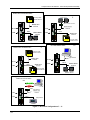
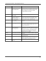
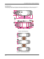
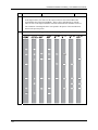
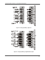
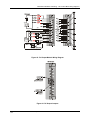
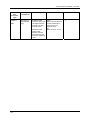
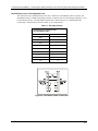
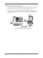
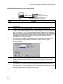
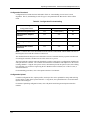
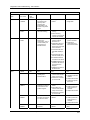
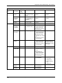
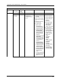
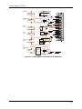
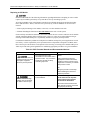
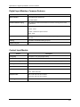
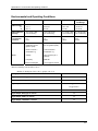
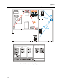
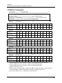
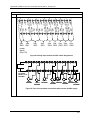
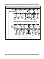
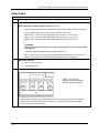
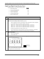
Table 2 shows the ways the two ports can be configured simultaneously.
Table 2 Simultaneous serial port configurations
See
RS232 Port Configured as
RS485 Port configured as
Figure 16 #1
ELN device*
ELN device*
Figure 16 #2
Controller is Modbus Slave
ELN device*
Figure 16 #6
Controller is one of multiple Modbus slaves**
ELN device*
Figure 16 #3
ELN device*
Controller is Modbus Slave
Figure 16 #4
Controller is Modbus Master to single slave
ELN device*
Figure 16 #5
Controller is Modbus master to multiple
slaves**
ELN device*
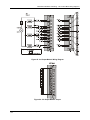
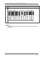
Figure 17 #7
Controller is Modbus slave
Controller is Modbus master to multiple
slaves
Figure 17 #8
Controller is Modbus master to multiple
slaves
Controller is Modbus slave
Figure 17 #9
Controller is Modbus slave
Controller is Modbus slave
Figure 17 #10
ELN device*
Controller is Modbus master to multiple
slaves
Figure 17 #11
Controller is Modbus slave via modem
ELN device*
*Such as Honeywell HCDesigner configuration software running on a PC or Honeywell 1040/559 Operator Interface
**Requires RS232-RS485 converter
Revision 5
9/03
HC900 Hybrid Controller Installation and User Guide
19
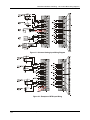
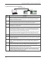
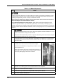
Components and Architecture - Serial Ports (RS232 and RS485)
1
ELN and ELN
2
Modbus Slave and ELN
3rd Party HMI
Modbus Master
ELN Protocol
RS-232
RS-232
RS 485
2000 Ft
ELN protocol
2000 Ft
RS 485
3
ELN and Modbus Slave
Modbus Slave
Protocol
ELN protocol
Modbus Master and ELN
4
Modbus Slaves
Honeywell
A
IL
M
%
RS232 to RS485 Converter
ELN Protocol
RS232.
RS-232
RS-232
RS 485
2000 Ft
2000 Ft
RS 485
Modbus Slave
Protocol
Modbus Master Protocol
ELN protocol
3rd Party HMI
Modbus Master
Modbus Slave and ELN
5
Modbus Master and ELN
6
3rd Party HMI
Modbus Master
Modbus
Slave
RS232.
RS232 to RS485 Converter
Modbus Master
Protocol
RS-232
Modbus Slave
Protocol
RS-232
RS 485
2000 Ft
ELN protocol
RS 485
2000 Ft
ELN protocol
Figure 16 Serial Port Configurations 1 - 6
20
HC900 Hybrid Controller Installation and User Guide
Revision 5
9/03
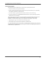
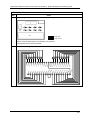
Components and Architecture - Serial Ports (RS232 and RS485)
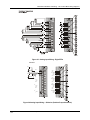
7
Modbus Slave and Modbus Master
Modbus Master and Modbus Slave
3rd Party HMI
Modbus Master
RS 485
%
Honeywell
A
IL
M
Honeywell
A
IL
M
2000 Ft
RS 485
Modbus Master
Protocol
%
%
Modbus Master
Protocol
RS-232
2000 Ft
Honeywell
A
IL
M
RS232 to RS485 Converter
Modbus Slave
Protocol
RS-232
8
Modbus Slaves
Honeywell
A
IL
M
Modbus Slave
Protocol
%
3rd Party HMI
Modbus Master
Modbus Slaves
ELN and Modbus Master
10
9
Modbus Slave and Modbus Slave
3rd Party HMI
Modbus Master
RS-232
RS 485
ELN Protocol
Modbus Slave
Protocol
RS-232
RS 485
Modbus Slave
Protocol
2000 Ft
3rd Party HMI
Modbus Master
2000 Ft
Honeywell
A
IL
M
Modbus Master
Protocol
%
Honeywell
A
IL
M
%
Modbus Slaves
11
PC Application for Dial Out Function
Modbus Slave/SixNet Modem
ELN
Modem
RS-232
RS 485
ELN Slave or
Modbus Slave
Protocol
2000 Ft
ELN protocol
Figure 17 Serial Port Configurations 7 – 11
Revision 5
9/03
HC900 Hybrid Controller Installation and User Guide
21
Components and Architecture - Networking Basics Reference
See also
Refer to Communications Installation on page 85 for details on communications.
Networking Basics Reference
The following information provides a basic reference for identifying and applying networking concepts,
components, and methods. It is intended primarily as a language bridge between users who have a limited
knowledge of networking, but who need to incorporate networking mechanisms in process control systems,
and Information Technology (IT) professionals who are adept in network implementation.
Networking topics are many and broad. To be useful, the networking language bridge given here includes
topics that apply to HC900 Controllers and to closely related computer and networking devices.
Ethernet
Ethernet is a networking standard (IEEE 802.3) that features:
• Local Area Network (LAN), which means that networked devices are near to each other (usually in the
same building)
• "bus" or "star" topology. Bus topology means that all networked devices (also called nodes) connect to
a common cable at different locations. Star topology means that a networking device (called a hub or
"concentrator") provides interconnections for cables from network nodes.
• Transmission speed of 10 Mbps or 100 Mbps
• CSMA/CD access. CSMA/CD stands for Carrier Sense Multiple Access/Collision Detection. All
devices on the LAN are free to transmit at will. If two nodes that are inter-connected at Hubs transmit
simultaneously, the collision of the multiple access is detected by the hardware devices associated with
the nodes. Each device will wait a random time, and will attempt to re-transmit. If the device detects
another collision, it will double wait time before transmitting again. Doubling the wait time is called
"exponential back-off".
Node Addressing
Every node on a network has a unique number and or name that is used by transmission protocols to
identify it as the Source or the Destination of a message. When it is manufactured, every node is given a
hard-coded Media Access Control (MAC) address that can be sensed by other nodes on the network. When
it is placed on an Ethernet network, each node is also given an Internet Protocol (IP) address, which is
stored in non-volatile memory, and which identifies it uniquely on that network.
Open Systems Interconnection Reference Model (OSI)
The OSI Model provides a reference source of all the methods and protocols needed to connect one
computer to another over a network. Although details of networking systems often differ from those
specified in the OSI Model, this model is used widely for design and manufacture of networking
components as well as networking systems from networks are constructed. The Features of the OSI Model
are summarized in Table 3.
Networking Protocols
A network protocol is a set of rules, or syntax, for exchanging data between nodes. In a very simple
system, a single protocol is required. For most networking systems used in commercial and industrial
applications, several protocols are required. Some protocols operate in one layer of the OSI model, while
others operate in more than one layer. For example, Transport Control Protocol/Internet Protocol (TCP/IP)
is commonly on the Internet and is used in private networks such as an HC900 Controller LAN. TCP
22
HC900 Hybrid Controller Installation and User Guide
Revision 5
9/03
Components and Architecture - Networking Basics Reference
operates in Layer 3, IP operates at Layer 2, and Ethernet itself includes protocols that operate at Layers 1
and 2.
Revision 5
9/03
HC900 Hybrid Controller Installation and User Guide
23
Components and Architecture - Networking Basics Reference
Characteristics of Networking Devices
Table 2 summarizes the characteristics of a set of "generic" networking devices. The information in this
table is intended to provide a basic overview of each type of device. Many devices that are currently
available are hybrids that combine features of more than one device type included in the table.
Glossary of Networking Terms
A glossary of networking terms is given in Table 5. Each term entry and description in this table is
included as an element of a language bridge between users of an HC900 Controller network and personnel
who are employed to implement the construction of the network. This glossary is not represented as
complete and sufficient for implementing a network. Rather, it is intended as a starter and as a pointer to
other more complete and authoritative works that are available commercially and in formal study programs.
24
HC900 Hybrid Controller Installation and User Guide
Revision 5
9/03
Components and Architecture - Networking Basics Reference
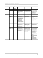
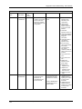
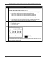
Table 3 - Open System Interconnection Model
Layer
Function
Number .. Name
7. Application
Identifies communications
partners, quality of service,
authentication and privacy,
and syntax constraints
Components
reside in:
Protocols
PC Networking
Software (e.g.,
Windows Client,
Novell Client32)
FTP
(examples)
SMTP
Network
components
affected (examples)
Networking software
packages in PC hosts
Modbus
drivers
6. Presentation
Translation between
application format and
network format, including
data encryption; also
compression/de-compression
5. Session
Establishes, manages, and
terminates connections
between applications (client to
server or peer to peer.)
4. Transport
Transparent transfer of data
between hosts. Error recovery
and flow control.
PC Software (e.g.,
Windows
NT/2000, Novell
NetWare)
TCP
UDP
Networking
packages in PC hosts
and in controllers
3. Network
Routing and Forwarding,
addressing, inter-networking,
error handling, congestion
control, packet sequencing
Software (e.g.,
Modbus/TCP)
IP
Routers
2. Data-Link
NIC drivers
(Includes 2 sublayers:
MAC: Frame
assembly/disassembly, error
detection/correction,
addressing
Ethernet
802.3
MAC (Media
LLC: call setup/termination
Network nodes
(devices with MAC
addresses, usually
Network Interface
Cards) and
networking devices
such as Switches.
Cable, NICs
Ethernet
802.3
1.
Access Control)
2.
LLC (Logical
Link Control)
1 . Physical
Revision 5
9/03
Electrical transmission of bits
from one node to another
HC900 Hybrid Controller Installation and User Guide
25
Components and Architecture - Networking Basics Reference
Table 4 - Networking Device Types
Network
Device
Hub
Description
Notes
A Hub is so called because a diagram of its
connections resembles a hub of a spoked
wheel.
Characteristics:
Echoes a message on any port to all other
ports; constitutes a collision domain for all
connected devices.
Isolates the device(s) on a "bad" port.
Switch
A Switch is similar in appearance to a Hub, but
connects only the ports specified as Source and
Destination devices in each message packet.
Collision domains are partitioned; that is, they
are isolated to Source/Destination devices.
26
Repeater
Extends the distance over which network
traffic can be transported; all message packets
at input port are repeated at the output port (no
domain partitioning). Signals are amplified,
but are not re-shaped or re-timed.
Bridge
An intelligent Repeater that connects input and
output ports, but only if the message specifies
the device on the output port as the
Destination.
Router
An intelligent Bridge that is often used for
wide area networks (WANs). Usually includes
a computer with its own network address,
memory, and network-based software. It can
be configured to determine which data packets
received will be transferred to a LAN node
based on destination address (such as an
HC900 controller and/or protocol port
number).
Gateway
A PC set up to inter-connect two disparate
network models at any combination of layers
of the OSI Model.
HC900 Hybrid Controller Installation and User Guide
Revision 5
9/03
Components and Architecture - Networking Basics Reference
Table 5- Glossary of Networking Terms
Name/Acronym
Name/Definition
10Base-Tx
Specification for 10mbps
carried over twisted-pair
cable.
ARP
Address Resolution
Protocol
AUI
Bit
bps
Bridge
Attachment Unit Interface
A unit of binary data.
Bits Per Second
A networking device that
connects two LANs and
forwards or filters data
packets between them,
based on their destination
addresses.
A network that uses
multiple carrier frequencies
to transmit multiplexed
signals on a single cable.
A hybrid networking device
that includes functions of a
router and of a bridge.
A LAN topology in which
all nodes are connected to a
single cable.
A data unit of eight bits
Category -3, -5 Ethernet
twisted-pair cable, available
as Unshielded Twisted Pair
(UTP) or Shielded Twisted
Pair (STP)
Broadband
Network
Brouter
Bus
Byte
Cat-3, Cat-5, Cat5E
CGI
Common Gateway Interface
Channel
Path through network
devices from one node to
another.
Electrical transmission
medium with solid wire
conductor at center,
insulated from and
surrounded by tubular outer
metal conductor.
Coaxial Cable
Revision 5
9/03
Comments
In the name 10Base-T, the “10” refers to 10 Mbps
transmission speed, the “Base” refers to Baseband,
which means that no frequency multiplexing is
applied, and the “-T” refers to Twisted Pair
conductors in the cable.
Precedes IP communication between two stations.
Deduces Layer 2 MAC address information from
IP address information.
(See MAU, MDI)
A binary bit has two values: 1 or 0.
Units of transmission speed
Bridges operate at data link level (or MAC layer)
of the OSI model
Bridges are transparent to protocols and to higherlevel devices like routers.
Several networks can coexist on a single cable
without interference with each other.
A Brouter routes specific protocols such as TCP/IP
and bridges others.
A data transmission from any node is received by
all other nodes on the Bus.
10Base-T can use Cat-3 or Cat-5 cable. Cat-3
includes 4 wires (2 twisted pairs). Cat-5 includes
8 wires (4 twisted pairs). 100Base-T can only use
Cat-5 cable.
(Note: Cat-5 cabling and connectors are more
reliable than those for Cat-3. Cat-5E refers to the
Enhanced version of Cat-5.)
Both Cat-3 and Cat-5 cables are limited to 100
meters (328 feet) per segment, and both use RJ-45
connectors.)
A programming standard that connects databases
and web browsers.
Examples are Thin Ethernet (RG-58/AU or
RG48/CU) and Thick Ethernet (RG-8) with BNC
connectors. Coaxial cable was commonly used for
earlier networks; Twisted-Pair is popular in current
use.
HC900 Hybrid Controller Installation and User Guide
27
Components and Architecture - Networking Basics Reference
Name/Acronym
Collision
Collision
Detection
Crosstalk
Cross-over Cable
CSMA/CD
CSU/DSU
Cut-Through
Data Link
Data Link Layer
Datagram
DCE
DHCP
Name/Definition
Comments
Simultaneous transmission
of two nodes on the same
channel.
An indication to the Data
Link Layer that node
contention (simultaneous
transmission) is present at
the Physical Layer.
Collisions can be reduced (and network capacity
increased) by use of Switches, which partition and
isolate collision domains.
Collision Detection causes both nodes to abort
transmission, set a random delay, and attempt retransmission. If contention recurs, each device
doubles delay time before re-transmission;
successive redoubling is called “exponential backoff”.
Electrical noise coupled
between media elements
Ethernet cable that enables
connection of DCE to DCE
equipment, or DTE to DTE
equipment.
Carrier Sense Multiple
Access w/ Collision
Detection
Channel Service Unit/Data
Service Unit
Method used by switches
for filtering messages, based
on the first few bytes.
A logical connection
between two nodes on a
network.
Layer 2 of the OSI Model
that is media-independent,
and functions above Layer 1
(Physical Layer).
A series of bits in an
ordered, intelligible
sequence.
Data Communications
Equipment
Dynamic Host
Configuration Protocol
DNS
Domain Name System
Domain
On the Internet, a named
network.
In MS Windows, an
elemental administrative
(security-oriented) unit.
28
In a "cross-over" cable, wiring crosses over from
the Transmit connection pair at one end to Receive
connection pair at the other end.
All nodes on the same network are free to initiate
message transmission. If two nodes transmit
simultaneously, the collision is detected, and both
nodes abort transmission and attempt to re-transmit
after a pause.
Converts data from format used by telephone
company to format usable on LAN.
Enhances transmission speed, but reduces
transmission security and/or reliability.
Defines protocols for data packets and how they
are transmitted between networking devices.
Includes two sublayers: Media Access Control
(MAC), and Logical-Link Control (LLC).
Datagrams are commonly referred to as “Packets”,
because they are data entities, although Packets
apply only the top layer (Application Layer of the
OSI Model.
Devices that transport data between DTE devices.
Runs in a DHCP server, which assigns an IP
address to each node that connects to the network.
(Can not be used in a an HC900 LAN.)
An Internet system (resident in a Web Browser)
that resolves domain names to IP addresses. (For
example, Http://www.yahoo.com resolves to
Http://204.71.202.160.)
User Names/Passwords, and related data on a
network.
HC900 Hybrid Controller Installation and User Guide
Revision 5
9/03
Components and Architecture - Networking Basics Reference
Name/Acronym
Domain Name
DS1, DS3
DTE
Name/Definition
A text name, appended to
the Host name.
Dedicated leased telephone
lines
Data Terminal Equipment
Ethernet
IEEE networking standard
802.3, which defines
configuration rules for an
Ethernet network
FTP
File Transfer Protocol
Filtering
Selection process used by a
Switch or a Bridge to
forward a message or block
its passage.
Inter-network security
system
Firewall
Firmware
Semi-permanent storage
medium.
Forwarding
Bridge or Switch, passing a
message from one network
to another, based on packet
filtering.
Dividing messages into
groups of bits, each group
having specific significance.
Framing
Host Name
hostid
The name assigned to
identify a computer
connected to a network.
A list of TCP/IP Host
Names/IP Addresses for a
network
Host Identifier
Hub
See “Port Multiplier”.
HTTP
Hypertext Transfer Protocol
Internet
A system of networks
(local, regional, national,
and international) linked by
TCP/IP.
Host Table
Revision 5
9/03
Comments
Identifies a node as a member of a domain.
DS1 (T-1) carries 1.544 Mbps, DS3 (T-3) carries
44.736 Mbps
Computers, Controllers, and other devices that
communicate via networking devices.
10 or 100 Mbps, Baseband network that uses
various media (thick coax, thin coax, twisted pair,
or fiber optic cable).
Example: 10BaseT is 10 Mbps Twisted Pair.
Use for send and receive files between an FTP
client and an FTP Server.
The Switch or Bridge reads the content of a packet
(such as destination address) to determine whether
the message should be blocked or forwarded.
Application software that runs in a computer, or a
dedicated firewall device that includes a dedicated
computer and software. In either case, it is placed
in the data path between networks.
In some cases, the content of firmware is fixed, and
cannot be altered. In other firmware (e.g., Flash),
the content can be re-written.
See “Filtering”.
Framing techniques vary with protocols used.
Typically, message data is preceded by an
identifying “header” and is followed by an errorcheck sequence.
The name is resident in each Host computer.
The portion of the IP address (right part) that
uniquely identifies a Host device on a network.
Application-Layer protocol that controls
transactions between the web client and the web
server.
Access to the Internet is governed by a world-wide
set of rules. IP (Internet Protocol) addresses are
assigned by Internet Corporation for Assigned
Names and Numbers(ICANN)
HC900 Hybrid Controller Installation and User Guide
29
Components and Architecture - Networking Basics Reference
Name/Acronym
Name/Definition
IP Address
Internet Protocol Address
ISDN
Integrated Services Digital
Network
Corrupted and/or incessant
data transmitted onto a
network.
Kilobits per second
A program used widely for
file transfer and terminal
emulation.
Local Area Network
Jabber
Kbps
Kermit
LAN
Latency
MAC
Delay in transmission
caused by a Switch or
Bridge in forwarding a
message.
One of the seven layers in
the OSI model.
Logical Link Control layer
Transferring tasks from
heavily-loaded resources to
less-loaded resources.
A temporary connection
between source and
destination devices.
Media Access Control
MAC Address
MAC coded ID
MAU
MDI
Medium Attachment Unit
Medium Dependent
Interface
Layer
LLC
Load balancing
Logical Link
30
Comments
Guaranteed unique address, assigned by the
Internet Corporation for Assigned Names and
Numbers (ICANN). IP address includes four
“octets” (eight bits, translating to integers from 0 to
255), separated by periods.
ICANN assigns three classes of addresses:
Class A – first (leftmost) octet is assigned; the
three rightmost octets are assignable to the owner
of the Class A address.
Class B – first and second (leftmost) octets are
assigned, the remaining two are assignable by the
owner of the Class B address
Class C – the three leftmost octets are assigned;
only the rightmost octet is user-assignable. The
number 0 is reserved for router connections to
another network, 127 for loopback testing, and 255
for broadcast to all computers on the network.
Digital service provided by telephone companies.
Caused by a failed Network Interface Card, or by a
computer device that transmits packets whose
length violates network rules.
Transmission speed.
Networked devices, logically isolated from other
networks and devices.
Layer 2 of the OSI Model
Ethernet Interface (transceiver, software to
physical media)
Unique code “burned" into firmware by the device
manufacturer.
(Also see AUI, MDI, MAC)
Physical connector at cable end (e.g., RJ-45 plug
on Ethernet CAT 5 cable.) (Also see AUI, MAU)
HC900 Hybrid Controller Installation and User Guide
Revision 5
9/03
Components and Architecture - Networking Basics Reference
Name/Acronym
Name/Definition
Comments
Modbus TCP/IP
Variant of Modbus protocol
Modem
Modulator-Demodulator; a
device for translating data in
differing media and/or
format.
Transmission of a message
with multiple destinations.
Network software that
translates text-format names
into numeric IP addresses
Microsoft networking
protocols
Network Identifier
Modbus TCP/IP is a derivative of related Modbus
protocol used with RS-232 or RS-485 data
acquisition and supervisory structures. Basically,
Modbus TCP/IP encapsulates Modbus messages in
TCP frames for transport in an Ethernet network.
Modems are commonly used for transmitting
digital data over analog telephone lines. A modem
is required at each end of the link.
Multicast
Name Server
NetBIOS
/NetBEUI
netid
Netware
Network
Network operating System
(NOS) by Novell
A system of
interconnections in which
networking devices such as
Hubs, Bridges, etc transport
messages between
computing devices.
Network Address
A code that resides in a
networked device, and that
identifies the device
uniquely on the network(s)
to which it is connected.
Network
Management
Administrative services that
include configuration,
tuning, performance
monitoring, and problem
diagnosis and repair.
NIC
Network Interface Card
Revision 5
9/03
See also “DNS”.
Used with Microsoft LAN Manager and Windows
NT products.
The portion of the IP address (left part) that
identifies the network.
“Computing devices” often include Personal
Computers (PCs), but also can include other
computer-based devices such as process
controllers, operator interface units, and graphical
trending devices.
The identifying code is usually numeric, but
additional, text-oriented Name codes can for added
user convenience in device identification.
Network addresses usually include a MAC address
and an IP address, and may also include Host
Name (for a PC) or other text-oriented user name.
Many commercial and industrial facilities have
large networks that are managed by full-time,
professional IT employees. Other facilities
contract the services of professional IT agencies.
For networks that are dedicated for special
purposes (process control, for example), and are
uncomplicated and easy to control, Network
Management is sometimes assigned to local
employees as a part-time, add-on responsibility.
Advised judgment is recommended.
The NIC is plugged into one of the PC’s expansion
slots. It includes the hardware and software (OSI
Layer 1 and Layer 2) required for connecting the
PC to the network.
HC900 Hybrid Controller Installation and User Guide
31
Components and Architecture - Networking Basics Reference
Name/Acronym
Node
OPC
Name/Definition
Comments
Any intelligent device that
includes a hardware address
that can be recognized by
other network devices.
Object Linking and
Embedding (OLE) for
Process Control
The “node” terminology is sometimes limited to
computing devices such as PC hosts, but can also
include networking devices such as Switches and
Routers.
OPC is an open standard that defines the exchange
of information between cooperating software
applications. OPC is based on the Distributed
Common Object Model (DCOM) defined by
Microsoft Corporation.
OPC server and client software runs in computers
interconnected on a network, and enables
exchanges between process control devices and
PCs configured as HMIs.
The OSI model is established by International
Standards Organization (ISO) to enable computer
communications using disparate media and
protocols. Includes seven “Layers”; refer to "OSI
Reference Model” for more information.
The content of a packet varies with the protocols
that are applied. It includes the data message itself
and various routing and control information such as
source and destination addresses.
In many cases, a packet includes a set of frames for
one protocol embedded (or encapsulated) in a set
of frames for another protocol. (Several levels of
encapsulation could be incorporated in a packet.)
For 10BaseT networking devices, ports are RJ-45
connectors.
The Port Multiplier (a.k.a. Hub) forwards a
message at any of its ports to all of its other ports,
with no isolation between the devices on these
ports. Hence, a Hub constitutes a “collision
domain” for all connected devices.
Provides Router-to-Router and host-to-network
connections over both synchronous and
asynchronous circuits.
Services print requests from other nodes on the
network.
OSI Model
Open Systems
Interconnection Reference
Model
Packet
A bit sequence that is
transmitted as an entity on a
network.
Port
The physical connection on
a networking device.
A “concentrator” (e.g., a
Hub) is a multi-port device
that enables one device to
be connected to several
others.
Point-to-Point Protocol
Port Multiplier
PPP
Print Server
Protocol
A PC dedicated to printer
management.
A system of rules for
communicating over a
network.
Remote Access
Access to a network from a
remote computer
Repeater
Receives signals on an
incoming cable, reshapes
signal form and restores
timing, then repeats the
signal on an outgoing cable.
32
Remote access usually uses a telephone line or the
Internet. The remote computer becomes a node on
the accessed network by assuming control of a
node actually on the network.
A Repeater can extend the distance over which a
message can be transported, but it also expands the
time for transport.
HC900 Hybrid Controller Installation and User Guide
Revision 5
9/03
Components and Architecture - Networking Basics Reference
Name/Acronym
RJ-45
Router
Shared Ethernet
SMTP
SNMP
SQE
Name/Definition
Style of connector at end of
Ethernet twisted-pair cable
A device that is capable of
filtering messages based on
IP addresses.
Configuration that binds
several network segments in
a single collision domain.
Simple Mail Transport
Protocol
Simple Network
Management Protocol
Signal Quality test
Straight Cable
Ethernet cable that enables
connection of DCE to DTE
equipment.
Subnet Mask
Defines the netid (Network
ID) and the hostid (Host ID)
parts of an IP address.
Switch
Multi-port device that
connects several network
segments on an addressselective basis
T-1, T-3
TCP/IP
(See DS1, DS3.)
Transport Control
Protocol/Internet Protocol
Comments
Routers differ from Bridges and Switches in that
those devices can only read MAC addresses.
(See “Port Multiplier”.)
Enables transmittal of E-Mail. Details are
available in RFC 821.
Enables a TCP/IP Host to collect network statistics
from other Hosts.
Often referred to as “heartbeat”.
In a "straight" cable, the Transmit wiring pair at
one end is wired directly to Transmit wiring pair
connections at the other end, and the Receive pair
at one end is wired to the Receive pair at the other
end.
The netid uniquely identifies a network, and the
hostid uniquely defines a computer on the network.
The Subnet Mask can be used to partition the
network into sub-networks, using parts of the
hostid to define new netids, or more correctly,
subnetids.
Portioning a network in this way enables switches
and routers to use the subnetids to reduce collision
domains and to promote security.
A Switch uses (MAC) source and destination
addresses in each packet to establish the
appropriate channel from the sending node to the
receiving node. The Switch looks very much like a
Hub, but differs in that ports are isolated from each
other, eliminating the multi-segment collision
domain that is characteristic of a Hub.
Transmission Control Protocol (TCP):
- operates at the Transport Layer of the OSI Model.
- manages connections between computers.
(Also see User Datagram Protocol [UDP]).
Internet Protocol (IP):
- operates at the Network Layer (one step below
TCP)
- defines how data is addressed (source/destination)
Revision 5
9/03
HC900 Hybrid Controller Installation and User Guide
33
Components and Architecture - Networking Basics Reference
Name/Acronym
Name/Definition
Comments
Telnet
Application that provides a
terminal interface between
hosts using TCP/IP.
Telnet defines a protocol that allows a remote
terminal session to be established with an Internet
host, so that a remote user has can use the remote
host as though he was sitting at a terminal
connected directly to the Host.
Throughput
Data volume transmitted per
unit of time.
A network topology in
which the nodes are
addressed and can transmit
in a fixed sequence.
The configuration scheme
for a network.
Example: 10 Mbps
UDP
User Datagram Protocol
Similar to Transport Control Protocol (TCP), but
less complex regarding reliability features, and
hence, faster than TCP.
Uplink Port
Ethernet Port that enables
inter-connection of
networking devices
VLAN
Virtual Local Area Network
VPN
Virtual Private Network
WAN
Wide-Area Network
Some Hubs and some Switches include an
additional port that enables connection form hub to
hub, hub to switch, etc. Typically, the Uplink Port
is a cross-over connector; on some devices, the
Uplink Port can be configured (or selected) as
either cross-over or straight.
Provides access to multiple IP subnets at a physical
location.
Remote access via a secure (encrypted) “tunnel”
though the Internet.
Typically, a network that includes several LANs at
different geographical locations, interconnected
using common carrier transmission services.
WINS
Windows Internet Name
Service
Token Ring
Topology
34
The “token” is a special code that is passed from
node to node in the same fixed sequence. Each
node can hold the token for a limited time, and can
transmit only as long as it holds the token.
Types of network topology include Ring, Bus, Star,
and Tree.
HC900 Hybrid Controller Installation and User Guide
Revision 5
9/03
Pre-Installation Planning - Networking Basics Reference
Revision 5
9/03
HC900 Hybrid Controller Installation and User Guide
35
Pre-Installation Planning - Overview
Pre-Installation Planning
Overview
Methodical pre-planning of an installation will preclude false starts and errors that can cause costly
hardware re-configuration and/or poor system performance. Some considerations in pre-installation
planning should include:
36
•
Power Supply Budgeting
•
Environmental conditions such as temperature, humidity, and other characteristics of the physical plant
site.
•
Equipment placement, particularly if the locations of field devices warrant the use of separate and/or
remote IO hardware.
•
Selection and placement of ancillary equipment such as equipment enclosures, conduits, and raceways
for wiring and cabling.
HC900 Hybrid Controller Installation and User Guide
Revision 5
9/03
Pre-Installation Planning - Power Supply Selection
Power Supply Selection
To determine which power supply to use, calculate power requirements below.
ATTENTION
Using inadequate power supply will cause the controller to cycle power on and off.
Enter quantity of each module type in column A and calculate the 5V and 24V maximum current in
columns D and E. Sum the maximum current for all module types and determine if the 900P02 power
supply is appropriate.
A
Module type
Quantity
B
C
D
E
Max Current
Max Current
5V
24V
@ 5 V in mA
@ 24 V in mA
mA Sub. Tot
mA Sub. Tot
(D=A*B)
(E=A*C)
Controller
(
)
600
0
(
)
(
)
Scanner
(
)
600
0
(
)
(
)
Analog Input (8 pts)
(
)
40
25
(
)
(
)
Analog Output (4 pts)
(
)
40
200
(
)
(
)
AC Digital Input (16 pts)
(
)
230
0
(
)
(
)
DC Digital Input (16 pts)
(
)
230
0
(
)
(
)
Contact Input (16 pts)
(
)
230
40
(
)
(
)
AC Digital Output (8 pts)
(
)
220
0
(
)
(
)
DC Digital Output (16 pts) (
)
430
0
(
)
(
)
(
)
140
100
(
)
(
)
Relay Output (8 pts)
Total 5V= (
Total mA
1. Is total 5V less than 2000?
Yes/No
2. Is total 24V less than 900?
Yes/No
) Total 24V= (
)
3. If the answer to 1 and 2 are YES, go to 4. If the answer to 1 or 2 is NO, use power supply 900P01-0001.
4. Multiply 5V total by 5.1.
(
)
5. Multiply 24V total by 24.5.
(
)
6. Sum results of 4 and 5.
(
)
7. Divide results of 6 by 1000
(
)
8. Is the result of 7 less than 28?
Yes/No
9. If the answer to 8 is Yes, use power supply 900P02-0001
10. If the answer to 8 is No, use power supply 900P01-0001
Revision 5
9/03
HC900 Hybrid Controller Installation and User Guide
37
Pre-Installation Planning - Environment
Environment
Environmental Operating Limits
The environmental conditions required for operating the HC900 Hybrid Controller are listed Table 6.
Table 6 - Operating Limits and Installation Guidelines
Condition
Specifications
Ambient Temperature
32°F to 131°F (0°C to 55°C) or (0°C to 60°C) with derating
Relative Humidity
10 % to 90 % RH at 40°C (104°F)
Vibration
Frequency
Acceleration
14 Hz to 250 Hz
1g
Mechanical Shock
Acceleration
Duration
Electromagnetic Interference (EMI) and
Radio Frequency Interference (RFI)
1g
30 ms
Meets the requirements of the EMC directive, 89/336/EEC.
Evaluated to EN61326:1997 + A1 for emissions and
immunity.
Power
Voltage
Frequency (Hz)
38
100 Vac to 240 Vac
47 to 63 Hz
Power Consumption
Typical 110VA@ 115VAC, maximum 130VA @ 264VAC
Class 1, Division 2 Installations
CONTROLLER RACK MUST BE MOUNTED INSIDE A
SECURE ENCLOSURE
General Installation
Install per NEC requirements for Open Type Equipment
HC900 Hybrid Controller Installation and User Guide
Revision 5
9/03
Pre-Installation Planning - Orientation of Rack Mounting
The HC900 Controller must be mounted in suitable equipment enclosures. That is, all components such as
the Controller rack, IO Expander Racks, and the Operator Interface manufactured by Honeywell must be
mounted in approved furniture designed for industrial applications.
Orientation of Rack Mounting
Racks must be mounted as indicated in illustrations throughout this manual, so as to provide for vertical
airflow through the racks. That is, racks must never be mounted vertically, and must never be mounted
with the backplane horizontal (for example, flat on a horizontal panel or tabletop). Environmental
specifications apply only to the normal mounting configuration.
Heat Rise De-rating
The HC900 is rated to operate at 60o C. However, for maximum reliability, the following guidelines should
be observed for applications above 52o C.
1.
Locate lower-power modules (Analog Input , Contact Input, etc) beside the Controller Module, and
keep higher-power modules (AC Output, AC Input, etc) away from the Controller Module. For power
consumption of each module, refer to Table 7.
2.
For 240 Vac applications and temperatures above 56o C, or 264Vac, 52o C , de-rate the number of ON
inputs per AC input module. (See AC Input de-rating data, see Figure 18.)
3.
Limit the number of Analog Output modules to a maximum of 10 per rack. . (See Figure 19.)
Table 7 - Power Applied, by Module Type
Module
Revision 5
9/03
HC900 Controller
Power (Watts)
Field Power
(Watts)
Total Power
(Watts)
Controller
2.3
0.0
2.3
Analog Input
1.0
0.0
1.0
Analog Output
4.3
0.0
4.3
Contact Input
2.0
0.0
2.0
Relay Output
2.4
0.0
2.4
DC In (@ 24V)
1.0
2.6
3.6
DC In (@ 32V)
1.0
5.1
6.1
DC Out
2.3
1.2
3.5
AC In (@120V)
1.0
1.9
2.9
AC In (@ 240V)
1.0
7.7
8.7
AC Out
1.0
12.0
13.0
HC900 Hybrid Controller Installation and User Guide
39
Pre-Installation Planning - Heat Rise De-rating
Figure 18 - AC Input Module de-Rating
Figure 19 - Power Supply De-rating
40
HC900 Hybrid Controller Installation and User Guide
Revision 5
9/03
Pre-Installation Planning - Equipment Placement Considerations
Equipment Placement Considerations
Factors that determine where equipment should be located within the site include at least the following:
•
Environmental conditions (see above).
•
Wiring/cabling characteristics. The HC900 Controller includes (optional) I/O expansion racks (C50
CPU only), which provide options regarding methods of connecting field devices into the system. That
is, the length of I/O wiring can be reduced significantly by locating I/O expansion racks remote from the
Controller rack, but close to process equipment. Following are samples of valid system architecture.
NOTE: Cable lengths specified in this manual are absolute. When planning for routing of cables and wires,
be certain to include vertical and horizontal routing within cabinets, raceways, and conduits. For
planning hints, refer also to Appendix A of this manual.
Controller Rack, with Local I/O
(only). In this case, all wiring is from
field devices to I/O modules in the
local rack.
Maximum length of RS-232 cabling
(Controller to PC) is 50 feet (15.2
meters).
Maximum length of RS-485 cabling
(Controller to Operator Interface) is
2000 feet (609.6 meters).
Controller rack, with one I/O
expansion rack.(C50 CPU only)
Maximum length of Ethernet cabling
(Controller to I/O expansion rack) is
328 feet (100 meters).
Controller rack connected via
Ethernet Hub to up to four I/O
expansion racks. (C50 CPU only)
Length of Ethernet cable:
• (Local Rack to Ethernet Hub):
≤ 328 feet (100 meters)
• Hub to any I/O expansion rack -
≤ 328 feet (100 meters)
Revision 5
9/03
HC900 Hybrid Controller Installation and User Guide
41
Pre-Installation Planning - Electrical Considerations
Controller rack connected via two
Ethernet Hubs to I/O expansion
racks (C50 CPU only)
Length of Ethernet cable, each
segment: 328 feet (100 meters).
Note: The use of Ethernet cables in excess of 100 meters and/or devices other than approved Hubs
(2 Maximum) will cause transmission delays that could have adverse affects on Controller performance.
It is advantageous to minimize length of I/O wiring. However, it is also a good idea to locate racks (and
wiring) away from adverse environmental conditions such as sources of RFI, EMI, and away from areas
with high levels of moisture, dust, and corrosive materials.
Electrical Considerations
The HC900 Controller should be mounted in an appropriate metal enclosure. A diagram that shows
recommended wiring practice for the cabinet enclosure is given in Figure 20 - Cabinet Wiring, Single
Chassis, and Figure 21 - Cabinet Wiring, Multiple Chassis.
Deviations from the installation conditions specified in this manual may invalidate this product's
conformity with Low Voltage and EMC Directives.
Hazardous voltages exist in the equipment enclosure.
•
Identify and avoid contact with voltage sources.
Failure to comply with these instructions could result in death or serious injury.
Controller Grounding
PROTECTIVE BONDING (grounding) of this controller and the enclosure in which it is installed shall be
in accordance with National Electrical Code (ANSI/NFPA 70) and with local electrical codes.
42
HC900 Hybrid Controller Installation and User Guide
Revision 5
9/03
Pre-Installation Planning - Electrical Considerations
Figure 20 - Cabinet Wiring, Single Chassis
Figure 21 - Cabinet Wiring, Multiple Chassis
Revision 5
9/03
HC900 Hybrid Controller Installation and User Guide
43
Pre-Installation Planning - Electrical Considerations
CE Conformity
Electrical noise produces undesirable effects in measurements and control circuits.
Digital equipment is especially sensitive to the effects of electrical noise. You should use the following
methods to reduce these effects:
•
Supplementary bonding of the controller enclosure to a local ground, using a No. 12 (4 mm2) copper
conductor, is recommended. This may help minimize electrical noise and transients that may adversely
affect the system.
•
Separate external wiring - group connecting wires into bundles (see Table 8) and route the individual
bundles through separate conduits or metal trays.
•
Use shielded twisted pair cables for all Analog I/O, Process Variable, RTD, Thermocouple, dc millivolt,
low level signal, 4-20 mA, Digital I/O, and computer interface circuits. Ground shields as described in
the section Input/Output Installation and Wiring.
•
Use suppression devices for additional noise protection. You may want to add suppression devices at the
external source. Appropriate suppression devices are commercially available.
•
Refer to document 51-52-05-01 How to Apply Digital Instrumentation in Severe Electrical Noise
Environments for additional installation guidance.
Grouping Wires for Routing
Wires that carry relatively high electrical energy can produce unwanted noise in wires that transmit signals
of relatively low energy, particularly when they are placed parallel in long wiring runs. Collect and bundle
wires of similar type, and route the bundle separate from bundles of other types. Table 8 provides
suggested guidelines for grouping wires.
Table 8 - Guidelines for Grouping Wires
Wire Group
High voltage
(>50 Vdc/Vac)
Wire Functions
• AC Line power wiring
• Earth ground wiring
• Control relay output wiring
• Line voltage alarm wiring
Signal
(<15 Vdc)
Analog signal wire, such as:
• Input signal wire (thermocouple, 4 mA to 20 mA, etc.)
• 4-20 mA output signal wiring
• Slidewire feedback circuit wiring
Communications
Low voltage
(<50 Vdc/Vac)
44
• Low voltage alarm relay output wiring
• Low voltage wiring to solid state type control circuits
HC900 Hybrid Controller Installation and User Guide
Revision 5
9/03
Pre-Installation Planning - Electrical Considerations
System Monitor Function Blocks
The HC900 Controller includes function blocks that enable the user to monitor the status of system
functions. When constructing a control configuration, add the following function blocks to the control
strategy:
• ASYS - System Monitor
• FSYS - Fast System Monitor
• RK - Rack Monitor
These function blocks are described in the HC900 Function Block Reference Guide.
Master Control Relay
A Master Control Relay (MCR) structure is a safety mechanism for shutting down the process control
system in emergency conditions. This mechanism, which is hard-wired (provided and installed by the
User) can include several Emergency Stop switches., strategically located near process equipment. An
example of an MCR structure is given in Figure 22.
Operating any of the Emergency-Stop switches opens the holding path for the MCR. When the MCR
de-energizes, the MCR contact opens, disconnecting all AC power that is supplied to AC Input Modules
and to AC Output Modules. Notice that AC power is disconnected only from the AC input/output modules.
Power is still available to Power Supplies at the Controller Rack and at each I/O expansion rack. The
Controller Module and the Scanner Modules in the racks continue to execute diagnostics and other
programs.
The Master Control Relay does not remove power from the Controller rack or from any of the I/O
expansion racks.
• Before performing service tasks such as installation of terminal connections or fuse replacement, use the
appropriate switch(s) to disconnect power from the power supply at each module.
• Ensure that wiring design precludes over-riding of the MCR by operator actions.
Failure to comply with these instructions could result in death or serious injury.
Class 1, Division 2 Installations
• DO NOT REMOVE OR REPLACE MODULES WHILE CIRCUIT IS LIVE UNLESS THE AREA IS
KNOWN NOT TO CONTAIN FLAMMABLE VAPORS.
Revision 5
9/03
HC900 Hybrid Controller Installation and User Guide
45
Pre-Installation Planning - Electrical Considerations
Figure 22 - Master Control Relay Wiring Example
46
HC900 Hybrid Controller Installation and User Guide
Revision 5
9/03
Pre-Installation Planning - Electrical Considerations
Rack Dimensions
Rack dimensions, including overall dimensions and patterns for drilling holes for mounting, are given in Figure 23.
Vertical spacing of racks, which is required for rack ventilation and for routing wires, is shown in Figure 24.
Figure 23 - Rack Dimensions
Figure 24 - Vertical Spacing of Racks
Revision 5
9/03
HC900 Hybrid Controller Installation and User Guide
47
Pre-Installation Planning - Electrical Considerations
Site Plan Documentation
Documenting the plan for installing a process control structure yields significant benefits:
•
The task of installation planning itself is facilitated.
•
Properly organized documentation greatly facilitates each step of the installation process, particularly
when planners and installers are different persons.
•
After initial installation, good documentation facilitates modification and troubleshooting.
•
For long-term maintenance, good documentation aids in the orderly transfer of knowledge required for
safe and secure process operations.
Time and effort spent at the beginning of a project is quickly recovered in the efficient execution of each
planning and installation procedure. To reduce the burden of documenting an HC900 Controller
installation, several data-collection aids are given in Appendix A of this manual. These include:
•
sample diagrams ("maps") of site facilities and of networking systems
•
fill-in templates that aid in collection and organization of installation data.
Use of these documentation aids will ease the task of coordinating hardware installation tasks with software
configuration tasks (for example, placement and wiring of I/O modules and configuring Rack, Module, and
Channel data in the configuration file.)
48
HC900 Hybrid Controller Installation and User Guide
Revision 5
9/03
Installation Guide - Overview
Installation Guide
Overview
This section contains procedures for installing one or more HC900 Controllers. It is recommended that the
Site Plan Documentation, completed as a part of Pre-Installation Planning, is used as a primary data source
and checklist while performing these procedures.
It is also recommended that the Site Plan Documentation and the information in this section be reviewed
together before beginning the installation. Familiarity with the overall procedure will help to prevent errors
and will promote efficiency in general.
Tools Required
The primary tools required during installation are listed in Table 9.
Equipment Preparation
A checklist for site preparation is given in Table 10.
Table 9 - Installation Tools
Item
Description
Comments
Common tools
1
• Wire strippers
For Power Supply and for I/O Wiring
2
• Crimper
For Terminal Lugs on Power Supply wiring
and on I/O wiring shields
3
• Screwdrivers
4
−
Small flat-tip
For Euro-style Terminal Blocks
5
−
Small/medium flat-tip or Phillips
For Barrier style Terminal blocks); also for
captured screws in Terminal Blocks
−
Large (long blade)
For use as I/O Module extractor
6
7
• Electric drill, with drill bits for #10 or M4
For rack mounting
screws, and with drill-bit extender
8
• Vacuum cleaner, brush
For use during and after drilling operations
9
• Pen, ball-point or felt-tip, for entering data on
For entering data on labels for I/O modules
labels for I/O modules)
10
• Multi-Meter (Volt/Ohms/Amps)
For safety checks and for equipment test
11
• Soldering pencil or gun (for attaching filter
For attaching filter capacitors on I/O wiring
shields
capacitors to I/O wiring shields)
Special tools
• Precision meters
Revision 5
9/03
(If required) for testing Analog calibration;
refer to Analog Calibration in this manual.
HC900 Hybrid Controller Installation and User Guide
49
Installation Guide - Overview
Table 10 - Site and Equipment Preparation
Step
1
Procedure
Referring to Site Planning Documentation, ensure that
sufficient numbers of the following items are on hand:
• Racks (4-, 8- and 12-slot)
Reference
Site Planning Documentation
In this Manual:
•
• Power Supplies (1 per rack)
Section on Pre-Installation
Planning.
• Controller Module or Scanner (1 per rack)
•
Sections on installation
• I/O Modules (correct type for each configured slot)
•
Appendix A
• Terminal Blocks, Barrier or Euro style, (1 for each I/O
Module)
• Jumpers 2-position or 10-position, (for designated
Terminal Blocks)
• Tie Wraps (1 or 2 for each Terminal Block)
• I/O Label (one per terminal block, by module type)
• Filler Block Cover (1 for each slot not occupied by an
I/O Module)
• Blank label (1 for each Filler Block Cover)
• Grounding Bars for I/O wiring shields (1 or 2 for each 4-
slots in each rack)
• Wiring terminal lugs (for connecting I/O shields to
grounding bars)
• Sheet metal screws, steel #10 or M4, for mounting racks
in enclosures (4 screws for 4-slot racks, 8 screws for 8- or
12-slot racks)
2
Install (or verify correct installation of) enclosures for HC900
Controllers and ancillary equipment:
Site Plan Documentation and
this section of this manual
• Mounting rails or flat-panels
• (for cabinet with multiple HC900 Chassis):
−
grounding bus
−
barrier strip for AC power
• Master control Relay
3
50
Install (or verify correct installation of) enclosures ("closets")
for networking devices:
HC900 Hybrid Controller Installation and User Guide
Appendix A.
Note : Some networking
devices may share enclosures
with HC900 Controller
components.
Revision 5
9/03
Installation Guide - Overview
Step
4
Procedure
Install (or verify correct installation of):
• External disconnect switches
Reference
I/O Module Installation section
in this manual.
• Fuses
at the power source associated with input sensor or output
devices for I/O modules.
5
Revision 5
9/03
Arrange and organize items to be installed at or near
enclosures, and use the Site Plan Documentation as a
checklist to verify readiness for installation.
HC900 Hybrid Controller Installation and User Guide
51
Installation Guide - Overview
Table 11 - Install HC900 Controller Components
Step
1
Procedure
Mount the Controller Rack
in the enclosure as follows.
Comments/References
For dimensions of the pattern for drilling holes, refer to the
diagram below.
• Using the diagram
below as a guide, mark
the locations for rack
mounting in the
enclosure for the top
holes in the rack.
(See CAUTION and
Note at right.)
• Drill and tap for # 10 (or
M4) screws.
• Start the mounting
screws (supplied by the
user) in the drilled
holes.
• Hang the Rack on the
screws at the top.
• Mark the locations for
the bottom screws.
(See CAUTION at
right.)
• Drill and tap for # 10 (or
CAUTION:
When drilling holes, prevent metal flakes from falling into
the rack, or onto any surface within the electrical cabinet.
Note: Always mount racks as shown above. That is, never
mount vertically, or with backplane horizontal.
M4) screws.
• Remove the rack from
the enclosure.
52
HC900 Hybrid Controller Installation and User Guide
Revision 5
9/03
Installation Guide - Overview
Step
2
Procedure
Comments/References
Aluminum grounding bars
for I/O module wiring are
optional. They can be
mounted at top, at bottom,
or at top and bottom of the
rack, as indicated at right.
If grounding bars are
included, attach them with
two M3 screws (supplied
with grounding bars in
plastic bag).
Note: The plastic bag also
includes four M4 screws
for attaching the grounding
wire lugs, which are
attached later.
Attach the M4 screws
loosely to the grounding
bars for safe keeping.
3
Hang the rack in the
enclosure on the top
screws.
Start all screws in the
bottom of the rack, then
tighten all screws.
4
Carefully place the Power
Supply in the leftmost slot
in the Rack, ensuring that
the connector at the back
seats properly.
Insert a slot screwdriver in
the slots at the top and
bottom of the power supply
cover while pulling
backward to open the
cover.
Fasten the screws
(captured in the face of the
power supply) into the tabs
at top and bottom of the
rack.
Revision 5
9/03
HC900 Hybrid Controller Installation and User Guide
53
Installation Guide - Overview
Step
Procedure
Comments/References
5
Hazardous Voltage
• Ensure that wiring to the Power Supply is disconnected from the site AC source before
installing wiring.
• Do not remove Yellow/Green wire from grounding stud on the power supply.
Failure to comply with these instructions could result in death or serious injury.
Ensure that wiring to the
Power Supply is
disconnected from the site
source, and then connect
AC wiring to the power
supply as shown at right.
ATTENTION!
Do not connect PE Ground (Green) Wire
directly to terminal on Power Supply.
Note: The Yellow/Green
wire is supplied with the
power supply. The nuts
(w/star washers) for the
grounding stud are
provided in a kit (bagged
in a plastic bag with the
rack.) The power supply
has an internal fuse that is
not replaceable. A second
external fuse may be added
if desired. For P01 power
supply use 3.0A, slowblow for 115VAC
operation; 2.5A, slow-blow
for 230VAC operation. For
P02 power supply, use
2.5A, slow-blow for
115VAC operation; 2.0A,
slow-blow for 230VAC
operation.
Apply power, and then test
voltages at the test points
provided on the face of the
Power Supply.
Note: Test-points are
electrically connected to
the backplane of the rack.
If the power supply is not
properly seated in the
backplane connectors, no
voltage will be measured at
the test points.
54
HC900 Hybrid Controller Installation and User Guide
Revision 5
9/03
Installation Guide - Overview
Step
6
Procedure
Comments/References
Ensure that jumpers are
installed in J9 on the
Controller Module as
shown at right.
7
Ensure that AC power to
the rack is disconnected.
Carefully place the
Controller Module in the
local rack, immediately to
the right of the Power
Supply. Fasten it in place
with two captured screws
at top and bottom.
ATTENTION:
Do not install the battery
at this time. Installing the
battery before the
controller is configured
can substantially shorten
battery life. Install under
power after the controller
configuration is complete.
(For more information,
refer to Battery
Installation/Replacement,
page 152.)
Revision 5
9/03
HC900 Hybrid Controller Installation and User Guide
55
Installation Guide - Overview
Step
8
Procedure
Comments/References
For each I/O expansion
rack (C50 CPU only), set
the Scanner Module
jumpers to the appropriate
Rack Address as shown at
right.
Repeat steps 1through 5 for
each I/O expansion rack
(C50 CPU only).
Then, for each expansion
rack, insert the Scanner
Module immediately to the
right of the Power Supply,
and secure it in place with
the two captured screws in
the faceplate.
56
HC900 Hybrid Controller Installation and User Guide
Revision 5
9/03
I/O Module Installation and Wiring
Overview
This section contains descriptions of and procedures for installing I/O Modules in controller racks and in
I/O expansion racks(C50 CPU only).
Module Placement in Racks
Each input or output module is placed in an I/O slot in a rack as shown in Figure 25.
Each "slot" in a rack includes a set of guides that locate the circuit board in the rack and a 20-pin (4 x 5)
socket in the backplane that receives the associated 4 x 5-pin plug at the back of the IO module.
At the front of each IO module, a twenty pin (in-line) plug receives the associated 20-pin socket on the
back of a terminal block. When the I/O module is inserted into the rack and the terminal block is placed on
the circuit board, two captured screws in the terminal block are fastened to metal tabs on the rack.
Figure 25 - I/O Module Installation
•
Do not use an input/output terminal block if the terminal block is damaged, if the door is
missing, or if one or both mounting screws are missing.
•
Always tighten both terminal block screws before applying field power to the module.
•
•
Do not apply energized ("live") field wiring to an input/output module that is not installed in
one of the racks in the HC900 Controller.
Do not operate the controller without a Protective Earth connection.
Failure to comply with these instructions could result in death or serious injury.
Revision 5
9/03
HC900 Hybrid Controller Installation and User Guide
57
I/O Module Installation and Wiring - Module Placement in Racks
Terminal Block Styles
The terminal block is available in the barrier style, shown at left in
Figure 26, and the Euro style, shown at right.
Both styles of terminal blocks have an embossed numbering "key"
that shows the numbering pattern of the 20 connections.
The frame associated with the terminal block has a transparent
hinged door. The hinged door is a tool secured cover. To open the
door, insert a flat screwdriver into the slot at the top and bottom of
the door while pulling out. The door has molded-in tabs that hold
labels, which are uniquely color-coded to identify each module type.
Each label is printed on both sides. On the front (visible when the
door is closed) are I/O channel numbers, with spaces in which
tagnames can be written. On the back (visible when the door is
open) are wiring patterns for the type of module located in the slot.
Figure 26 - Terminal Block Styles
The 20-pin, inline connectors at the back of the terminal blocks are universal; that is, any type of I/O
module can be used with either the Barrier style or the Euro style terminal block.
ATTENTION
Before mounting terminal blocks in the rack, be sure they are properly keyed to the module
type they will be used with. See I/O Installation Procedures, page 63.
Terminal Block Colors and Keying
Both the barrier style and the Euro style are available in two colors (red and black). Black terminal blocks,
which have gold-colored contacts, are used for low-voltage, low-energy signals such as contact inputs and
low DC voltages. Red terminal blocks, which have tin-colored contacts, are used for higher voltages such
as 120/240 Vac.
Colors of each Terminal Blocks must correlate to that of the mating header on I/O modules with which they
are used; that is:
•
Black terminal blocks, which have gold-colored contacts, are for use with I/O modules that have black
headers and gold-colored pins in the 20-pin connector; these include: Analog Input, Analog Output,
DC Input, DC Output, and Contact Input.
•
Red terminal blocks, which have white (tin) contacts, are for use with I/O modules that have red
headers and white- (tin-) colored contacts in the 20-pin connector; these include: AC Input, AC
Output, and Relay Output.
•
Terminal blocks may be keyed by the installer to prevent high voltage terminal blocks from being
installed on low voltage modules. See Table 14.
Any of the color-coded labels will fit into the door of any terminal block. Use care to ensure that all
hardware components match each other, and also match the control strategy in the configuration file. Use
of documentation aids in Appendix A will facilitate correct use of labels.
58
HC900 Hybrid Controller Installation and User Guide
Revision 5
9/03
I/O Module Installation and Wiring - Remote Termination Panel (RTP)
Remote Termination Panel (RTP)
The optional Remote Termination Panel (RTP) provides an easy way to connect the HC900 controller to
the field wiring. The RTP integrates some of the typical externally connected components, reducing wiring
and setup time. It also minimizes the need for multiple wires under a single screw connection by
expanding the connectivity of the shared terminals of the I/O modules.
See Appendix B Installation of Remote Termination Panels (RTPs) for details.
Terminal Block-to-Field (Signal) Wiring
Although both of the two available terminal block styles can be used on all I/O module types, wiring
methods vary with the module type and with the type of field devices connected to the terminal block. The
descriptions that follow provide details.
Wiring can be routed through the terminal block at the top, at the bottom, or both. Wiring should be fixed
in place using wire ties at the slotted tabs that are molded in at top and bottom of each terminal block.
Wiring Rules and Recommendations
In general, stranded copper wire should be used for non-thermocouple electrical connections. Twisted-pair
wiring with shielded cable will improve noise immunity if wire routing is suspect.
Wire Gage
Observe all local codes when making power connections. Unless local electrical codes dictate otherwise,
the recommended minimum wire size for connections is given in Table 12.
Table 12 - Minimum Recommended Wire Sizes
Wire Application
Wire
Gauge
14
Earth ground to common power supply.
14 to 16
AC to power supply
10 to 14
Earth ground wire
20
DC current and voltage field wiring
22
DC current and voltage wiring in control room
Routing and Securing Wires
Typically, field wiring is routed to connections at a terminal panel near the controller and then from the
terminal panel to the terminal blocks on the I/O modules.
Whatever method of routing is used, wiring must be mechanically supported along its length, and must be
protected from physical damage and electromagnetic (noise) interference. (Refer to Installation Planning,
Environmental Considerations, in this manual.)
Also, all wires must be securely terminated, using appropriate wiring practices.
Revision 5
9/03
HC900 Hybrid Controller Installation and User Guide
59
I/O Module Installation and Wiring - Terminal Block-to-Field (Signal) Wiring
Signal Grounding
The shield for each input should be grounded at the
grounding bar (optional) at the top or bottom of each rack
as indicated in Figure 27. For low-frequency noise
rejection, I/O wiring shields should be grounded only at the
controller end.
For high-frequency noise rejection, shields should be
grounded at the controller and at the field device. If the
ground voltage potential at the field device is different
from that at the controller, a DC isolation capacitor should
be used between the shield and the grounding bar on the
rack.
Figure 27 - Signal-Wire Grounding
Aluminum grounding bars for I/O wiring are available as options. When selected for use, they are fastened
to the top and/or bottom of each rack, as indicated in Figure 28. To enable connection of multiple ground
wires with a single screw, the wires can be twisted together and secured with a wire lug.
To facilitate module replacement, it is advisable in most cases to route all wiring through either the top or
the bottom of the terminal block. This
allows the terminal block to pivot up or
down, allowing ready access to the
module, and is the preferred method
for a limited number of wires.
For a larger number of wires, or for
wires of a heavier gauge, it is advisable
to route some wires through the top of
the terminal block, and some through
the bottom, as indicated in Figure 28.
In this case, it is necessary to adjust
wire length so as to ensure adequate
flexibility of the twisted wires and to
provide clearance sufficient to remove
the I/O module.
Figure 28 - Wire-Shield Grounding
60
HC900 Hybrid Controller Installation and User Guide
Revision 5
9/03
I/O Module Installation and Wiring - Terminal Block-to-Field (Signal) Wiring
Terminal Block Jumper Combs
Two styles of terminal block jumper combs are available for use with the barrier-style terminal blocks: tenposition and two position.
The ten-position jumpers are used with AC
output modules to inter-connect L1 (AC Hot) of
all channels.
The two-position jumpers are used to connect
Common (DC negative or AC neutral) for the DC
input module, the DC Output Module, and the
AC Input Module. Each of these module types
has groups of eight channels, with the two groups
isolated from each other. The two-position
jumper connects (Common) terminals 10 and 12,
making one group of sixteen non-isolated
channels.
The two-position jumper can also be used to
connect the V+ terminals on the DC Output
Module.
Refer to the wiring information on each module,
given in this section of this manual.
Figure 29 - Terminal Block Jumper Installation
Revision 5
9/03
HC900 Hybrid Controller Installation and User Guide
61
I/O Module Installation and Wiring - Removal and Insertion Under Power (RIUP)
Removal and Insertion Under Power (RIUP)
Read and understand all of the following information regarding RIUP before attempting to remove and/or
replace any I/O module, particularly in a system that is actively controlling a process.
All of the I/O Module types in the HC900 Controller System include the Removal and Insertion Under
Power (RIUP) feature. That is, while the rack is powered, any of the I/O Modules can be removed or
inserted:
•
With no physical damage to the module, to the rack, or to other modules in the rack
•
Without disturbing the functions of other I/O modules in the rack or in the system.
Under carefully controlled circumstances, this feature enables the user to remove and insert an I/O module
without completely shutting down a running system. However, it must be recognized that removing or
inserting an I/O module under power is potentially hazardous to property and to personnel.
Circumstances that dictate prudent actions depend on conditions and specific process applications at each
user facility. It is the responsibility of site personnel to know all potential consequences of RIUP, and to
take actions to prevent all adverse consequences before removing or inserting an I/O module under power.
Table 13 provides some general guidelines for establishing appropriate procedures at a given installation.
Table 13 - RIUP: Potential Hazards and Recommended Actions
Hazard
Source
Preventive Action(s)
Potentially lethal voltages on
Terminal Boards associated with
I/O Modules.
Disconnect all signals at terminal
blocks from sources of power before
removing the terminal block from
the I/O module.
Each signal at each of the
terminals for an I/O module has a
specific function. Any or all of the
signals may be vital for safely
controlling a process.
Either:
Hazardous Voltages
Loss of control or view of
a running process
Using trained personnel and
appropriate control mechanisms,
transfer to manual control for each
signal that is necessary to maintain
safe process control.
Or:
Bring the process to a safe stop
before initiating the removal or
insertion procedure.
EXPLOSION HAZARD
Class 1, Division 2 Installations
• DO NOT DISCONNECT EQUIPMENT UNLESS POWER HAS BEEN SWITCHED OFF OR THE
AREA IS KNOWN TO BE NON-HAZARDOUS.
62
HC900 Hybrid Controller Installation and User Guide
Revision 5
9/03
I/O Module Installation and Wiring - I/O Installation Procedures
I/O Installation Procedures
Table 14 - Connect Input/Output Wiring
Step
1
Procedure
Comments
Reference
Using Rack #, Slot #,
Channel # data from a
Hybrid Control Designer
report and/or from
documentation aids in
Appendix A for reference,
fill in the tagnames on the
Label for each configured
I/O Module.
Be sure to use the
appropriate label for each
module type.
2
Place the appropriate label
supplied with the module
(tagname side out) into the
hinged door for each I/O
Module.
Slotted tabs, molded into
the door at top and bottom,
hold the label in place.
.
3
(Optional): Install jumper
combs into designated
Barrier style Terminal
Blocks, to reduce the
wiring required to supply
power:
Two-position jumper for
the DC Input Module
and/or on the DC Output
Module.
Ten-position jumper for
the AC Output Module.
Five-position jumper (10position jumper cut in half)
for a Relay Output
Module.
Revision 5
9/03
Refer to terminal block wiring diagrams for specific information.
HC900 Hybrid Controller Installation and User Guide
63
I/O Module Installation and Wiring - I/O Installation Procedures
Step
4
Procedure
Comments
Reference
For each configured and
labeled I/O Module, break
off the "key-tabs" in the
pattern that identifies each
module type.
(For a diagram of each
key-tab pattern, use the I/O
Modules and/or the
diagram shown below.
64
HC900 Hybrid Controller Installation and User Guide
Revision 5
9/03
I/O Module Installation and Wiring - I/O Installation Procedures
Step
Procedure
Comments
Reference
NOTE:
In the diagram below, the white cut-outs represent the cut-outs on the modules that
accommodate tabs on the Terminal Block. That is, all key-tabs that line up with the
white cut-outs on the diagram should be retained, and all other tabs should be removed.
The orientation of the diagrams below corresponds to the picture of the terminal block,
shown in the previous picture.
Diagrams for I/O Module Key-Tabs
Revision 5
9/03
HC900 Hybrid Controller Installation and User Guide
65
I/O Module Installation and Wiring - I/O Installation Procedures
Step
5
Procedure
Using the following
reference items:
Comments
Reference
Barrier Terminal Block
• Hybrid Control Designer
data
• Documentation Aids
from Appendix A
• Labels in I/O Terminal
Block assemblies
• Wiring diagrams given
in this Section for each
type of I/O module
connect I/O wiring to the
terminal blocks for each IO
module.
Euro Terminal Block
Route wires through the
channel at left of the
terminal block, to exit
through the top or bottom
of the block.
6
Insert a wire-tie into the
top and/or bottom end of
the terminal block.
Form a bend in each wire
to provide strain relief, and
secure the wire bundle with
the tie.
66
HC900 Hybrid Controller Installation and User Guide
Revision 5
9/03
I/O Module Installation and Wiring - I/O Installation Procedures
Step
7
Procedure
Comments
Reference
Connect wire shield to
grounding bars on top
and/or bottom of the Rack.
(Refer to Signal
Grounding, at the
beginning of this section,
for suggestions and
recommendations.)
Revision 5
9/03
8
Install I/O modules in
racks.
9
In each slot location not
occupied by an I/O
module, install a Filler
Block cover, Part number
900TNF-0001.
Note: The Filler Block Cover looks much like an I/O Terminal
Block assembly, except that it does not include the wire
terminating block (screw terminals). The Filler Block mounts in
the same manner as a Terminal Block (with captured screws at
top and bottom). Blank labels are provided for mounting in the
hinged door.
HC900 Hybrid Controller Installation and User Guide
67
I/O Module Installation and Wiring - I/O Terminal Block Wiring Diagrams
I/O Terminal Block Wiring Diagrams
Universal Analog Input Module Wiring
The Universal Analog Input Module has eight inputs, which can include any combination of the following
input types: RTD, TC, Ohms, Millivolt, Volt, or Milliamp. Figure 31 shows wiring examples of each of the
analog input types. An example of wiring for eight TC inputs is given in Figure 33.
Specifications for this module and for other modules are given in the Specifications section of this manual.
Isolation
This module has eight inputs, which are isolated except for RTD current sources.
RTD Inputs
RTD inputs share current sources (two RTD inputs per
source), as shown in Figure 30, in Figure 31, and in
Figure 32.
For example, the current source for the RTD input at
channel one (terminals 1 and 2) is terminal 3 (IRTD 1 &
2). This same current source (IRTD 1 & 2) is also used
for an RTD input at channel two (terminals 4 and 5).
Figure 32 and Figure 35 show examples of RTD input
wiring (2-wire and 3-wire RTDs). Four-wire RTD
inputs are not available).
Figure 30 - RTD Inputs
OHMs Inputs
Ohms inputs are wired similar to 2-wire RTD inputs. That is, they require a current source, and thus must
use one of the IRTD current sources. Also, two terminals are jumpered together as they are for two-wire
RTD inputs.
Analog channels wired for Ohms inputs differ from RTD inputs in these aspects:
•
Ohms inputs connect to variable resistance devices other than RTDs, and
•
Ohms inputs are configured in Hybrid Control Designer as Ohms inputs, rather than as RTD inputs.
Examples of wiring for resistance inputs are given in Figure 34.
Shield Grounding
Shields must be grounded as described under Shield Grounding at the beginning of this section.
Hazardous voltages exist at terminal blocks.
•
Using switches at field devices, disconnect the field wiring from power sources before servicing.
Failure to comply with these instructions could result in death or serious injury.
68
HC900 Hybrid Controller Installation and User Guide
Revision 5
9/03
I/O Module Installation and Wiring - I/O Terminal Block Wiring Diagrams
Figure 31 - Universal Analog Input Wiring Diagram
Figure 32 - Examples of RTD Input Wiring
Revision 5
9/03
HC900 Hybrid Controller Installation and User Guide
69
I/O Module Installation and Wiring - I/O Terminal Block Wiring Diagrams
Figure 33 - Analog Input Wiring - Eight TCs
Figure 34 - Analog Input Wiring - Eight Resistance Inputs
70
HC900 Hybrid Controller Installation and User Guide
Revision 5
9/03
I/O Module Installation and Wiring - I/O Terminal Block Wiring Diagrams
Figure 35 - Analog Input Wiring - Eight RTDs
Slidewires
R
F
F
IN 1 +
IN 1 -
IN 1-
IRTD 1 & 2
IN 2 +
IN 2 +
IN 2 -
R
IN 1+
IRTD 1 & 2
IN 3 +
IN 3 -
IN 2 IN 3+
IN 3-
IRTD 3 & 4
IRTD 3 & 4
IN 4 +
IN 4 -
IN 4+
IN 4-
IN 5 +
IN 5 -
IRTD 5 & 6
IN 6 +
IN 6 IN 7 +
IN 5+
IN 5-
IRTD 5 & 6
IN 6+
IN 6-
IN 7 -
IN 7 +
IN 7-
IRTD 7 & 8
IRTD 7 & 8
IN 8 +
IN 8 -
IN 8+
IN 8-
Figure 36 Analog Input Wiring – Slidewire (Position Proportion Block)
Revision 5
9/03
HC900 Hybrid Controller Installation and User Guide
71
I/O Module Installation and Wiring - I/O Terminal Block Wiring Diagrams
Analog Output Module Wiring
An example of Analog Output Module wiring is shown in Figure 37. Specifications for this module and for
other modules are given in the Specifications section of this manual.
Isolation
The four outputs are isolated from each other.
Shield Grounding
Shields must be grounded as described under Shield Grounding at the beginning of this section.
Hazardous voltages exist at terminal blocks.
•
Using switches at field devices, disconnect the field wiring form power sources before servicing.
Failure to comply with these instructions could result in death or serious injury.
Figure 37 - Analog Output Wiring Diagram
72
HC900 Hybrid Controller Installation and User Guide
Revision 5
9/03
I/O Module Installation and Wiring - I/O Terminal Block Wiring Diagrams
DC Input Module Wiring
The DC Input Module has sixteen inputs, in two groups of eight inputs per group. The groups are isolated
from each other; inputs are non-isolated within each group. An example of Digital Input Module wiring is
shown in Figure 38. Specifications for this module and for other modules are given in the Specifications
section of this manual.
Shield Grounding
Shields must be grounded as described under Shield Grounding at the beginning of this section.
Common Terminals
Two common terminals are provided for each group of eight inputs. Terminals 9 and 10 are connected in
the input module, and terminals 11 and 12 are connected in the module.
Jumper Comb
A two-position jumper comb is available (as an option, for barrier-style terminal blocks only) for
connecting digital common wiring (at terminals 9 and 11 or 10 and 12). See Figure 39.
Hazardous voltages exist at terminal blocks.
•
Using switches at field devices, disconnect the field wiring from power sources before servicing.
Failure to comply with these instructions could result in death or serious injury.
DC Input
IN 1
IN 1
IN 2
IN 2
IN 3
IN 3
IN 4
IN 4
IN 5
IN 5
+ 10-32 Vdc -
IN 8
Com 1
(IN 1-8)
Com 2
(In 9-16)
IN 7
IN 8
Com 1
(IN 1-8)
Com 2
(In 9-16)
IN 9
IN 9
IN 10
IN 11
+ 10-32 Vdc -
IN 6
IN 6
IN 7
IN 12
IN 13
IN 14
IN 15
IN 16
IN 10
IN 11
IN 12
IN 13
IN 14
IN 15
IN 16
+ 10-32 Vdc Legend:
External
Disconnect
Fuse
User-Supplied Safety Devices
Figure 38 - DC Input Module Wiring Diagram
Revision 5
9/03
HC900 Hybrid Controller Installation and User Guide
73
I/O Module Installation and Wiring - I/O Terminal Block Wiring Diagrams
Figure 39 - DC Input Module Jumper
74
HC900 Hybrid Controller Installation and User Guide
Revision 5
9/03
I/O Module Installation and Wiring - I/O Terminal Block Wiring Diagrams
AC Input Module Wiring
The AC Input Module has sixteen inputs. An example of AC Input Module wiring is shown in Figure 40.
Specifications for this module and for other modules are given in the Specifications section of this manual.
Common Terminals
Two common terminals are provided for each group of eight inputs. Terminals 9 and 10 are connected in
the input module, and terminals 11 and 12 are connected in the module.
Jumper Comb
An optional two-position jumper comb is available as an option (for barrier style terminal blocks only) for
connecting digital common wiring at terminals 9 and 11 or terminals 10 and 12. See Figure 41.
Hazardous voltages exist at terminal blocks.
•
Using switches at field devices, disconnect the field wiring from power sources before servicing.
Failure to comply with these instructions could result in death or serious injury.
Figure 40 - AC Input Module Wiring Diagram
Revision 5
9/03
HC900 Hybrid Controller Installation and User Guide
75
I/O Module Installation and Wiring - I/O Terminal Block Wiring Diagrams
Figure 41 - AC Input Module Jumper
76
HC900 Hybrid Controller Installation and User Guide
Revision 5
9/03
I/O Module Installation and Wiring - I/O Terminal Block Wiring Diagrams
Contact Input Module Wiring
The Contact Input Module has sixteen inputs in one group. An example of Contact Input wiring is shown
in Figure 42
Specifications for the Contact Input Module and other modules are given in the Specifications section of
this manual.
Internally Powered Input Channels
The Contact Input Module provides voltage to the field contacts.
CAUTION
Do not apply any external power to the field device or to the input terminals. Doing so
could damage the module.
Common terminals
Four common terminals are provided for the 16 inputs. Terminals 9, 10, 11, and 12 are connected in the
Contact Input module.
Hazardous voltages exist at terminal blocks.
•
Using switches at field devices, disconnect the field wiring from power sources before servicing.
Failure to comply with these instructions could result in death or serious injury.
Figure 42 - Contact Input Wiring Diagram
Revision 5
9/03
HC900 Hybrid Controller Installation and User Guide
77
I/O Module Installation and Wiring - I/O Terminal Block Wiring Diagrams
DC Output Module Wiring
The DC Output Module provides 16 current-sinking outputs in two groups of eight points per group. The
two groups are isolated from each other; outputs are non-isolated within each group. Current sinking
means that a positive voltage potential is continuously applied to one side of each DC output load, and the
negative side of the load is switched internally in the module.
Specifications for this module and for other modules are given in the Specifications section of this manual.
Examples of DC Output wiring are shown in Figure 43 - DC Output Module Wiring Diagram
Over-Current Protection
Electronic high-current and high-temperature limiting provides overload protection; resets after cycling
power. Conventional external fuses may be used if desired.
Reverse-Polarity Protection
A potential of ± 34 Volts will cause no damage to the module; a reverse polarity power supply connection
allows continuous current flow to the loads that are not controlled by the On/Off state of the output circuits.
Jumper Comb
Two-position jumper combs are available (as an option for barrier style terminal blocks only) for
connecting digital common wiring between terminals 10 and 12, and for connecting +24Vdc between
terminals 9 and 11. See Figure 44.
+V Terminals
The +V1 (terminal 9) and +V2 (terminal 11) are the positive power supply input to power the output
circuits for the two groups of eight inputs per group. The +V supply must provide minimum 24 Vdc at 65
mA (min) per group.
Hazardous voltages exist at terminal blocks.
•
Using switches at field devices, disconnect the field wiring from power sources before servicing.
Failure to comply with these instructions could result in death or serious injury.
78
HC900 Hybrid Controller Installation and User Guide
Revision 5
9/03
I/O Module Installation and Wiring - I/O Terminal Block Wiring Diagrams
Figure 43 - DC Output Module Wiring Diagram
Figure 44 - DC Output Jumpers
Revision 5
9/03
HC900 Hybrid Controller Installation and User Guide
79
I/O Module Installation and Wiring - I/O Terminal Block Wiring Diagrams
AC Output Module Wiring
The AC Output Module provides eight output circuits. Each output is isolated from the other outputs. An
example of AC output wiring is shown in Figure 45. Specifications for this module and for other modules
are given in the Specifications section of this manual.
Output Loading
Voltage: 85 to 240 Vac
Maximum per output: 2.0A resistive load
Maximum per module: 8.0A
NOTE
When exceeding 1.0 A per output, it is recommended (but not required) to connect the high-current loads to
every other output - for example, outputs 1, 3, 5, 7 or 2, 4, 6, 8. This distributes heat more evenly across
the heat sink.
Jumper Comb
A ten-position jumper comb is available for inter-connecting all L1 (Hot) terminals (1, 3, 5, 7, 9, 11, 13, 15,
17, 19). See Figure 46.
Replaceable Fuses
Each output circuit on the AC Output Module includes a (plug-in) replaceable fuse.
Replacement fuse is from Wickmann, part #3741315041. This is a 3.15 Amp time lag fuse with UL/CSA
approval for 250 VAC.
Hazardous voltages exist at terminal blocks.
•
Using switches at field devices, disconnect the field wiring from power sources before servicing.
Failure to comply with these instructions could result in death or serious injury.
80
HC900 Hybrid Controller Installation and User Guide
Revision 5
9/03
I/O Module Installation and Wiring - I/O Terminal Block Wiring Diagrams
Figure 45 - AC Output Module Wiring Diagram
Figure 46 - AC Output Module Jumper
Revision 5
9/03
HC900 Hybrid Controller Installation and User Guide
81
I/O Module Installation and Wiring - I/O Terminal Block Wiring Diagrams
Relay Output Module Wiring
The Relay Output Module provides eight individually isolated, electromechanical relay outputs. Four of
the outputs are Form-C, and the other four are Form-A. A schematic showing the relationship of individual
Form-A relays and Form-C relays to external (user) connections is given in Figure 47.
Examples of Relay Output wiring as they relate to connections on the Terminal Block are shown in Figure
48.
Figure 47 - Schematic Example: Relay Output and External Wiring
Contact Rating
Maximum current/output: 4A at 250Vac/30Vdc with resistive load
Maximum current per module: No de-rating per module, but ensure compliance with maximum ratings
for each output.
Required Output Fusing
Outputs are not fused in the Relay module. Install a fuse for each output at the field device that is
appropriate for the load and the wire used.
Jumper Comb
A ten-position jumper comb, available for the AC Output Module, can be cut in half and used as shown in
Figure 49 to reduce the number of wires required to connect the Relay Output Module to AC Neutral or to
DC Common.
82
HC900 Hybrid Controller Installation and User Guide
Revision 5
9/03
I/O Module Installation and Wiring - I/O Terminal Block Wiring Diagrams
Hazardous voltages exist at terminal blocks.
•
Using switches at field devices, disconnect the field wiring from power sources before servicing.
Failure to comply with these instructions could result in death or serious injury.
Figure 48 - Relay Output Module Wiring Diagram
Revision 5
9/03
HC900 Hybrid Controller Installation and User Guide
83
I/O Module Installation and Wiring - I/O Terminal Block Wiring Diagrams
Figure 49 - Relay Output Module Jumpers
84
HC900 Hybrid Controller Installation and User Guide
Revision 5
9/03
Communications Installation
Overview
This section contains descriptions of and procedures and recommendations for installing communications
systems and components.
.
Table 15 - Connect Communications Wiring and Cabling
Step
1
Procedure
Comments
Reference
Determine requirements
for communications links
by referring to the site
diagrams. (Refer to
Appendix A.)
(Expansion I/O
C50 CPU only)
2
Refer to the diagram of the
controller at right, and to
Table 16 - Links to
Controller Communication
Ports for connection
details.
Connect communications
cabling as indicated by the
site cabling diagram.
(The Ethernet port for the
expansion rack is only
present for Model C50)
For Modbus connections,
see page 105.
Revision 5
9/03
HC900 Hybrid Controller Installation and User Guide
85
Communications Installation - Overview
Table 16 - Links to Controller Communication Ports
Controller
Port
/Connector
Type
Link Type:
Controller to
RS-232
(9-pin “D”
connector)
Desktop or
Laptop PC
Cable Type
To Device/Port
Reference Data
RS-232 Null Modem
cable, up to 50’
Or
RS-232 PC modem
cable, up to 50’
Serial port of PC (w/ Null
Modem cable)
For Wiring details of
Null Modem cable, 9pin Male/Female
connector, see Figure
50 - Null Modem Cable
Construction.
or
Modem. Refer to RS-232
Remote Connection to
PC Configuration Tool on
page 91.
RS-232
(9-pin “D”
connector)
Modbus master
(controller is
single slave)
RS-232 Null Modem
cable, up to 50’
Or
RS-232 PC modem
cable, up to 50’
RS232 to RS485
converter
Refer to device’s port
instructions
Page 20 Figure 16 &
Figure 17 #2, 7, 9
RS-232
(9-pin “D”
connector)
Modbus master
(controller is
one of multiple
slaves)
RS232 to RS485
converter
Refer to device’s port
instructions
Page 20 Figure 16 &
Figure 17 #6
RS-232
(9-pin “D”
connector)
Modbus slave
network
(controller is
master)
RS232 to RS485
converter
Refer to device’s port
instructions
Page 20 Figure 16 &
Figure 17 #4, 5, 8
RS-485
3-pin
Phoenix
1840379 (or
equivalent)
Operator
interface
Terminal connector of
operator interface. (Refer
to Table 18.)
Page 20 Figure 16 &
Figure 17 #1, 2, 4, 5, 6,
11
RS-485
3-pin
Phoenix
1840379 (or
equivalent)
Modbus master
(controller is
slave)
Belden #9271 (or
equivalent)
Refer to device’s port
instructions
Page 20 Figure 16 &
Figure 17 #3, 8, 9
RS-485
3-pin
Phoenix
1840379 (or
equivalent)
Modbus slave
network
(controller is
master)
Belden #9271 (or
equivalent)
Refer to device’s port
instructions
Page 20 Figure 16 &
Figure 17 #7, 10
10Base-T
Host, Peer,
and Internet
Devices
Shielded CAT5E
cable, up to 100
meters. A crossover
cable is required for
PC to Controller
connection;
otherwise, straight
cable.)
RJ45 connector on Host,
Peer, or Internet Device
RJ45
86
Belden #9271 (or
equivalent)
HC900 Hybrid Controller Installation and User Guide
Revision 5
9/03
Communications Installation - Overview
Controller
Port
/Connector
Type
Link Type:
Controller to
Cable Type
To Device/Port
10Base-T
I/O expansion
link(C50 CPU
only)
Shielded CAT5E
crossover cable, up to
100 meters between
Controller and hub,
and hub-to-hub.
Either:
RJ45 Connector Scanner
module of Rack #2 (no
other racks on I/O
Expander Link)
Or:
RJ45 connector on Hub
RJ45
Shielded CAT5E
straight cable
between controller
and expansion rack
and hub to expansion
racks.
Revision 5
9/03
HC900 Hybrid Controller Installation and User Guide
Reference Data
??
87
Communications Installation - Connecting the HC900 Controller to a PC with the Hybrid Control Designer Software
Connecting the HC900 Controller to a PC with the Hybrid Control
Designer Software
To establish communications between the HC900 controller and the Hybrid Control (HC) Designer
configuration software use any of the following methods:
•
A. Direct Serial RS-232 connection
•
B. Modem connection
•
C. Direct Ethernet connection
•
D. Networked Ethernet connection
These methods are described below.
88
HC900 Hybrid Controller Installation and User Guide
Revision 5
9/03
Communications Installation - Connecting the HC900 Controller to a PC with the Hybrid Control Designer Software
A. Direct Serial RS-232 Connection
Com1 - Com 8
PC
RS-232 Configuration port
RS-232
(9.6 - 38.4 KB)
Null Modem cable
Step
Procedure
1
Prepare a null modem cable. Refer to RS-232 Direct Link to PC Configuration Tool (page 90) for
specific instructions on the null modem cable.
2
Connect one end of the null modem cable to the HC900 controller’s RS-232 configuration port.
3
Connect the other end to an available serial port (COM1 through COM8) on your PC. Refer to RS232 Direct Link to PC Configuration Tool (page 90) for specific instructions on the null modem cable.
4
If a configuration is not available, start a new configuration in HC Designer by selecting File, New.
After selecting controller type and revision, select OK.
5
From the Utilities Worksheet (Utilities tab in the main window) in the HC Designer software, set up
the PC’s serial port attributes for use with the controller. Make sure that the same baud rate is set up
for the PC port and the controller. In general, the faster the baud rate the better the performance,
however, your PC may not communicate reliably at the faster baud rates. You may choose 9600
Baud (controller default), 19.2KB, or 38.4 KB. (Refer to the HC900 Hybrid Control Designer User’s
Guide or its respective on-line help, Setting Up PC Com Ports and Connections - PC Serial Com
Port Setup and Utilities Worksheet - Set Controller Serial Port, for details on this step).
6
On the PC, use the Utilities Worksheet in the HC Designer software to select the Com port as the
current port.
Revision 5
9/03
HC900 Hybrid Controller Installation and User Guide
89
Communications Installation - Connecting the HC900 Controller to a PC with the Hybrid Control Designer Software
RS-232 Direct Link to PC Configuration Tool
The Controller can be connected directly to the PC, in which case a Null Modem Cable is required. The
Null Modem cable is available from Honeywell (Part # 51404755-501) or from third-party suppliers, or can
be fabricated by the user. The Null Modem construction is shown in Figure 50 - Null Modem Cable
Construction. Cable Pinouts are shown in Table 17 - PC Cable Pinouts.
Table 17 - PC Cable Pinouts
Configuration Connector Pinouts
(For Null Modem Cable)
Signal Name
Terminal No.
DCD
1
RXD
2
TXD
3
DTR
4
GND
5
DSR
6
RTS
7
CTS
8
RI
9
Figure 50 - Null Modem Cable Construction
90
HC900 Hybrid Controller Installation and User Guide
Revision 5
9/03
Communications Installation - Connecting the HC900 Controller to a PC with the Hybrid Control Designer Software
RS-232 Remote Connection to PC Configuration Tool
The Controller can also be connected remotely by a set of modems, which are available from third-party
suppliers. In this case, PC Modem Cable is used between the Controller and the modem at one end, and
between the PC and the internal or external modem at the other end, as shown in Figure 51.
Remote controller access via dial-up modem is available via the communication setup in the PC
configuration tool. All functions of the Hybrid Control Designer configuration tool can be performed over
this link. Remote access functions include on-line monitoring, configuration upload and download, and
firmware upgrade.
Figure 51 - RS-232 Remote Access via Modems
Revision 5
9/03
HC900 Hybrid Controller Installation and User Guide
91
Communications Installation - Connecting the HC900 Controller to a PC with the Hybrid Control Designer Software
B. Modem Connection
Modem
9.6 - 38.4 KB
RS-232 Configuration port
PC
Internal Modem
assigned to a COM port
Step
92
Procedure
1
Connect a modem to the HC900 controller’s RS-232 configuration port. Refer to Modem
configuration examples (page 95) for a list of approved modems, their settings, and the connection
specifics.
2
On the PC, check on the Utilities Worksheet in the HC Designer software to see if the PC modem is
properly installed. A modem icon on the associated COM port button indicates the PC modem is
properly installed (internal or external). If the modem icon is not visible on the associated COM port
button, use the modem supplier’s instructions to properly install the modem and verify the installation
using the Windows’ Control Panel Modem property page to confirm proper installation.
3
Set up the phone book in the HC Designer software. This list includes the phone numbers for each
of the HC900 controllers that can be connected using a modem. The phone book can be accessed
from the Main Menu (View | Phone Book) or from the Utilities Worksheet by selecting the modem port
as the current port. (Refer to the HC900 Hybrid Control Designer User’s Guide or its respective online help, Setting Up PC Com Ports and Connections - PC Serial Com Port Setup and Remote
Access, for details on this step.)
4
On the PC, use the Utilities Worksheet in the HC Designer software to select the modem as the
current port. A button will appear to allow you to dial a selected controller.
HC900 Hybrid Controller Installation and User Guide
Revision 5
9/03
Communications Installation - Connecting the HC900 Controller to a PC with the Hybrid Control Designer Software
Modem requirements
Most commercially available modems can be used with the HC900 Controller. The modem must have the
following capabilities:
•
RS-232 interface
•
Auto answer
•
Can operate at 9600 or 19200 or 38400 baud, 8 data bits, 1 stop bit, and no parity
•
Hardware handshaking can be disabled
•
Software handshaking can be disabled
•
Data Terminal Ready (DTR) input can be disabled
•
Result codes can be suppressed
•
Echo can be disabled
•
Must be equipped with non-volatile memory (NVRAM) so that settings that are configured using
command strings can be retained during a power-outage
•
Must be able to load the NVRAM settings automatically on power-up
Cable requirements
You will need an interface cable to connect the modem to the DB-9 female on the controller. If your
modem has a 25-pin connector, be sure to use a DB-25 to DB-9 modem cable.
TIP
The Null Modem cable used to directly connect a PC running Hybrid Control Designer
software to the controller may typically not be used to connect the PC to the modem or to
connect the modem to the controller.
If your modem requires command string configuration, you will need an interface cable to connect the
modem to your PC. Refer to your modem and computer documentation to determine this cable’s
requirements.
Revision 5
9/03
HC900 Hybrid Controller Installation and User Guide
93
Communications Installation - Connecting the HC900 Controller to a PC with the Hybrid Control Designer Software
Modem configuration
Before connecting a modem to the controller’s RS-232 port (marked “CONFIGURATION”), the modem
must be configured with the following settings:
•
Baud Rate = 9600, 19200, or 38400 (Must match Baud Rate configured in HC900 Controller)
•
Parity = None
•
1 stop bit
•
8 data bits
•
No handshaking
•
Ignore DTR
•
Suppress result codes
•
Suppress echo
•
Auto answer
•
Disable command recognition (only necessary if the modem has this capability)
Some of these settings may be settable via switches. Others may require command strings to be written to
the modem using a PC terminal program such as Hyperterminal. You will need to refer to your modem’s
documentation to make this determination. Those settings that are configured using command strings must
be saved to the modem’s non-volatile RAM (NVRAM), and the NVRAM must be configured as the profile
that gets loaded when the modem is powered up.
Most modems are equipped with auto-recognition to set the baud rate, parity, stop bits, and data bits. If
your modem has no means of setting these using switches, then most likely it is equipped with autorecognition. To configure the port settings of a modem with auto recognition, do the following:
Step
Action
1
Connect the modem to a PC.
2
Power up the modem.
3
Start up a PC terminal program such as Hyperterminal.
4
Configure the PC COM Port for 9600, 19200, or 38400 baud (must match baud rate configured
in the HC900 Controller), no parity, 1 stop bit, and 8 data bits.
5
Establish communications with the modem. A common way of doing this is simply entering the
AT E1 Q0 command and seeing if the modem responds with OK.
Once you establish communication to the modem, its port settings are configured.
6
94
Save the port settings to the profile that gets loaded on power-up.
HC900 Hybrid Controller Installation and User Guide
Revision 5
9/03
Communications Installation - Connecting the HC900 Controller to a PC with the Hybrid Control Designer Software
Modem configuration examples
Below are procedures for setting up the following commercially available modems:
•
3Com US Robotics 56K Data/Fax External Modem
•
Zoom 56K Dualmode External Modem
•
Best Data 56SX Data Fax External Modem
•
SixNet VT-MODEM Industrial External Modem
3Com US Robotics 56K Data/Fax External Modem
Step
1
Action
Ensure that the switches are set to the factory settings:
Switch
Setting
Position
Function
1
OFF
UP
Normal DTR operations
2
OFF
UP
Verbal (word) results
3
ON
DOWN
Enable result codes
4
OFF
UP
Displays keyboard commands
5
ON
DOWN
Disables auto answer
6
OFF
UP
Modem sends CD signal when it connects with another
modem
7
OFF
UP
Loads Y0-Y4 configuration from user-defined
nonvolatile memory (NVRAM)
8
ON
DOWN
Enables recognition (smart mode)
2
Connect the modem to a PC. If your computer’s RS-232 port has a 25-pin connector, use a
DB-25 male to DB-25 female RS-232 cable. If your computer’s RS-232 port has a 9-pin
connector, use a DB-25 male to DB-9 female modem cable.
3
Power-up the modem.
4
Run a serial communication port program such as Hyperterminal.
5
Within the communication program, select the port to which the modem is connected.
6
Configure the port to these settings:
baud rate = 9600, 19200, 38400, 57600 (Must match Baud Rate configured in HC900
Controller)
data bits = 8
parity = none
stop bits = 1
flow control = none
7
In the program's terminal window, restore factory defaults by keying-in the following command
string:
AT &F0
Then, press the ENTER key.
The modem should respond with OK.
Revision 5
9/03
HC900 Hybrid Controller Installation and User Guide
95
Communications Installation - Connecting the HC900 Controller to a PC with the Hybrid Control Designer Software
Step
8
Action
Key in the following command string:
AT Y0
Then, press the ENTER key.
The modem should respond with OK.
9
Key in the following command string:
AT &B1
Then, press the ENTER key.
The modem should respond with OK.
10
Key-in the following command string:
AT E0 Q1 &W0
The Modem will not respond.
96
11
Power down the modem and disconnect it from the PC.
12
Set the modem switches to the following:
Switch
Setting
Position
Function
1
ON
DOWN
Modem ignores DTR (Override)
2
OFF
UP
Verbal (word) results
3
OFF
UP
Suppresses result codes
4
ON
DOWN
Suppresses echo
5
OFF
UP
Modem answers on first ring
6
ON
DOWN
CD always ON (Override)
7
OFF
UP
Loads Y0-Y4 configuration from user-defined
nonvolatile memory (NVRAM)
8
OFF
UP
Disables command recognition (dumb mode)
13
Connect the modem to the RS-232 port of the HC900 using a DB-25 male to DB-9 male
RS-232 cable.
14
Connect the modem to a telephone jack.
15
Power up the modem and the HC900 Controller.
16
On a remote computer, run Hybrid Control Designer software.
17
Set up Hybrid Control Designer software to dial the HC900 Controller.
18
Verify that communications is established with the remote HC900 Controller.
HC900 Hybrid Controller Installation and User Guide
Revision 5
9/03
Communications Installation - Connecting the HC900 Controller to a PC with the Hybrid Control Designer Software
Zoom 56K Dualmode External Modem
Step
Action
1
Connect the modem to a PC. If your PC’s RS-232 port has a 25-pin connector, use a DB-25
male to DB-25 female RS-232 cable. If your PC’s RS232 port has a 9-pin connector, use a
DB-25 male to DB-9 female modem cable.
2
Connect power to the modem.
3
Power up the modem.
4
Run a serial communication port program such as Hyperterminal.
5
Within the communication program, select the port to which the modem is connected.
6
Configure the port to these settings:
baud rate = 9600, 19200, or 38400, 57600 (Must match Baud Rate configured in HC900
Controller)
data bits = 8
parity = none
stop bits = 1
flow control = none
7
In the program's terminal window, restore factory defaults by keying-in the following command
string:
AT &F0
Then, press the ENTER key.
8
In the program’s terminal window, key-in the following command string:
AT E1 Q0
Then, press the ENTER key. The Modem should respond with OK.
9
Key-in the following command string:
AT &Y0 &C0 &D0 &R1 &S0 &K0 S0=1
Then, press the ENTER key. The Modem should respond with OK.
10
Key-in the following command string:
AT E0 Q1 &W0
Then, press the ENTER key. The Modem will not respond.
Revision 5
9/03
11
Power down the modem and disconnect it from the PC.
12
Connect the modem to the RS-232 port of the HC900 Controller using a DB-25 male to DB-9
male RS-232 cable.
13
Connect the modem to a telephone jack.
14
Power up the modem and the HC900 Controller.
15
On a remote computer, run Hybrid Control Designer software.
16
Set up the PC software to dial the HC900 Controller.
17
Use the PC software "Loop-back" feature to verify that communications are established with
the remote HC900 Controller.
HC900 Hybrid Controller Installation and User Guide
97
Communications Installation - Connecting the HC900 Controller to a PC with the Hybrid Control Designer Software
Best Data 56SX Data Fax External Modem
Step
Action
1
Connect the modem to a PC. If your PC’s RS-232 port has a 2- pin connector, use a DB-9
male to DB-25 female modem cable. If your PC’s RS-232 port has a 9-pin connector, use a
DB-9 male to DB-9 female RS-232 cable.
2
Connect power to the modem.
3
Power-up the modem.
4
Run a serial communication port program such as Hyperterminal.
5
Within the communication program, select the port to which the modem is connected.
6
Configure the port to these settings:
baud rate = 9600, 19200, 38400, 57600 (Must match Baud Rate configured in HC900
Controller)
data bits = 8
parity = none
stop bits = 1
flow control = none
7
In the program's terminal window, restore factory defaults by keying-in the following command
string:
AT &F0
Then, press the ENTER key.
8
In the program’s terminal window, key-in in the following command string:
AT E1 Q0
Then, press the ENTER key. The modem should give an OK response.
9
Key-in the following command string:
AT &C0 &D0 &K0 &R1 &S0 &Y0 S0=1
The Modem should respond with OK.
10
Key-in the following command string:
AT E0 Q1 &W0
The Modem will not respond.
98
11
Power down the modem and disconnect it from the PC.
12
Connect the modem’s serial cable to the RS-232 port of the HC900 using a DB-9 male to DB-9
male RS-232 cable.
13
Connect the modem to a telephone jack.
14
Power up the modem and the HC900 Controller.
15
On a remote computer, run Hybrid Control Designer software.
16
Set up the PC software to dial the HC900 Controller.
17
Use the PC software "Loop-back" feature to verify that communications are established with
the remote HC900 Controller.
HC900 Hybrid Controller Installation and User Guide
Revision 5
9/03
Communications Installation - Connecting the HC900 Controller to a PC with the Hybrid Control Designer Software
SixNet VT-MODEM Industrial External Modem
Step
Action
1
Connect the modem to a PC. If your PC’s RS-232 port has a 25 pin connector, use a DB-9
male to DB-25 female modem cable. If your PC’s RS-232 port has a 9 pin connector, use a
DB-9 male to DB-9 female RS-232 cable.
2
Connect power to the modem. You will need to supply an external power supply with a DC
voltage between 10 and 30 VDC.
3
Power-up the modem.
4
Run a serial communication port program such as Hyperterminal.
5
Within the communication program, select the port to which the modem is connected.
6
Configure the port to these settings:
baud rate = 9600, 19200, 38400, 57600 (must match baud rate configured in HC900
controller
data bits = 8
parity = none
stop bits = 1
flow control = none
7
In the program's terminal window, restore factory defaults by keying-in the following command
string:
AT &F0
Then, press the ENTER key.
8
In the program’s terminal window, key-in the following command string:
AT E1 Q0
Then, press the ENTER key. The modem should give an OK response.
9
Key-in the following command string:
AT &Y0 &C0 &D0 &R1 &S0 &K0 S0=1
The Modem should respond with OK.
10
Key-in the following command string:
AT E0 Q1 &W0
The Modem will not respond.
Revision 5
9/03
11
Power down the modem and disconnect it from the PC.
12
Connect the modem to the RS-232 port of the HC900 Controller using a DB-9 male to DB-9
male modem cable.
13
Connect the modem to a telephone jack.
14
Power-up the modem and the HC900 Controller.
15
On a remote computer, run Hybrid Control Designer software.
16
Set up the PC software to dial the HC900 Controller.
17
Use the PC software "Loop-back" feature to verify that communications are established with
the remote HC900 Controller.
HC900 Hybrid Controller Installation and User Guide
99
Communications Installation - RS-485 Link to Operator Interface
RS-485 Link to Operator Interface
The RS-485 port is located below the hinged plastic cover on the top part of the Controller Module.
Typically, the cable that interconnects this port to the Operator Interface must be fabricated during
installation, because it will probably be necessary to run the cable through conduit.
Table 18 - Parts needed for RS-485 Cabling
Part #
Quantity
Belden #9271 (or equivalent),
with 120 ohm resistors (2,000
feet Maximum)
Variable
Description
Commercially available communication
cable
Or
Belden #9182 (or equivalent),
with 150 ohm resistors (4, 000
feet maximum)
100
1
10-terminal connector (Supplied with the
operator interface)
Phoenix #1840379 (or
equivalent)
1
connector (3-pin) (Supplied with the
controller CPU module)
047260
1
Ferrite cable clamps (Supplied with the
operator interface)
089037
2
Nylon cable ties
HC900 Hybrid Controller Installation and User Guide
Revision 5
9/03
Communications Installation - RS-485 Link to Operator Interface
C. Direct Ethernet Connection to one HC900 controller
Defaults:
IP Address: 192.168.1.254
Subnet Mask: 255.255.255.0
Default Gateway: 0.0.0.0
Ethernet 10 Base-T
Crossover cable
Host 10Base-T Ethernet port, RJ-45 connector
Step
Procedure
1
Make sure the PC has an Ethernet NIC (Network Interface Card) installed and enabled.
2
Connect an Ethernet 10Base-T crossover cable to the HC900 controller’s Open Ethernet RJ-45 port
(top RJ-45 port).
3
Connect the other end of the Ethernet 10Base-T crossover cable to the PC’s network port.
4
On the PC, use the Utilities Worksheet in the HC Designer software to connect to the controller over
Ethernet. Every HC900 controller is shipped with the default IP address of 192.168.1.254 and Subnet
Mask of 255.255.255.0. You can use these network parameters initially for testing or configuration
use. In the Current PC to Controller Connection Settings area of the dialog box, click on the Network
button to bring up the Network Port Properties dialog box and Add the default IP address. Be sure the
Ethernet Network Interface Card in the PC has a fixed IP address on the same subnet as the
controller (192.168.1.x, where x= 2 to 253).
5
In the Current PC to Controller Connection Settings area of the dialog box, select Network for the
Port to be used and the default IP address for the Address. Click on Loopback to assure
communications between the PC and the controller. You may now use the Ethernet port for
configuration interface.
6
Consult your IT systems administrator for allocating IP addresses if this controller will require a
unique IP address within a plant network. Be also sure that the PC Network Interface Card has an IP
address that allows access to the controller on the subnet after changing the controller’s network
parameters.
7
You may change the controller’s IP address and related network parameters from its default using
the Utilities Worksheet in the HC Designer software. This may be done using either the RS-232 serial
port (typically used) via a null modem cable connection or the Ethernet connection from the PC to the
controller. If the RS-232 connection is desired, make sure the proper PC serial Com port to be used
has been set up (See Direct Serial RS-232 Connection above).
Revision 5
9/03
HC900 Hybrid Controller Installation and User Guide
101
Communications Installation - RS-485 Link to Operator Interface
Step
8
Procedure
Select the Set Controller’s Network Parameters button. Using the wizard (bottom radio button),
select the PC port to be used, then set the controller’s new network parameters including IP address,
Subnet Mask (if other than the default), and Default Gateway IP address (if required, otherwise use
default). Refer to the HC900 Hybrid Control Designer User’s Guide or its respective on-line help,
Utilities Worksheet - Set Controller’s Network Parameters, for further details on this step.
Note: This step will require the controller to be placed temporarily in the Program mode. After the
new network parameters have been downloaded, the controller will conduct a Cold Start in its
transition to RUN. This will cause an initialization if there is a current configuration in the controller.
102
HC900 Hybrid Controller Installation and User Guide
Revision 5
9/03
Communications Installation - RS-485 Link to Operator Interface
D. Network Access to one or more controllers
Ethernet 10Base-T LAN
Hub/Switch
PC
165.125.163.25
Step
165.125.163.26
Procedure
1
Make sure the PC has an Ethernet NIC (Network Interface Card) installed and enabled. Be sure the
NIC has an IP address (fixed or DHCP served) that allows access to controllers with IP addresses on
the same or other subnet. Consult your IT department or network administrator for allocating IP
addresses to the controllers if required.
2
You will need to set each controller’s IP address prior to network connection since every HC900
controller is shipped with the default IP address of 192.168.1.254. Placing multiple controllers on the
same network before they have been given unique IP addresses will cause problems.
3
On the PC, use the Utilities Worksheet in the HC Designer software to set up the serial RS-232
connection to the controller at the desired baud rate (see Direct Serial RS-232 Connection above).
This will require a null modem cable.
4
Select the Set Controller’s Network Parameters button. Using the wizard (bottom radio button), select
the PC COM port to be used, then set the controller’s new network parameters including IP address,
Subnet Mask, and Default Gateway (if required). See your IT network administrator for proper
entries. (Refer to the on-line help provided with the HC Designer software, Utilities Worksheet, Set
Controller’s Network Parameters, for further details on this step).
Note: This step will require the controller to be placed temporarily in the Program mode. After the
new network parameters have been downloaded, the controller will conduct a Cold Start in its
transition to RUN. This will cause an initialization if there is a current configuration in the controller.
5
Repeat step 4 for each controller on the same network.
6
Select the Network button at the bottom of the dialog box and Add any or all of controller IP
addresses configured to the list. This will allow selection of any of these Addresses for downloading
or uploading configurations.
7
You may now connect the controllers to your network for access by the Hybrid Control Designer
software. For the Networking Example shown, connect one end of the Ethernet 10Base-T cable to
the PC’s network port. Connect the other end of the Ethernet 10Base-T cable to the Ethernet
hub/switch.
8
Connect an Ethernet 10Base-T cable to each HC900 controller’s Open Ethernet RJ-45 port (top RJ45 port). Connect the other end of each Ethernet 10Base-T cable to the Ethernet hub/switch.
9
You may now access any controller on the network for configuration access by assigning Network as
the Port and the respective IP Address as the Address of the controller.
ATTENTION: When multiple controllers are on the network, be careful to check for the correct
IP address of the destination controller prior to download of a new configuration or when
downloading edits to a configuration while in RUN mode. Otherwise, you may inadvertently
download a configuration to the wrong controller.
Revision 5
9/03
HC900 Hybrid Controller Installation and User Guide
103
Communications Installation - RS-485 Link to Operator Interface
Setting Up the Controller Network Parameters
See the HC900 Hybrid Control Designer Users Guide, Doc. # 51-52-25-110 or respective HC Designer
Help Files for setting up following network parameters:
•
IP Address, Subnet Mask (optional), Default Gateway IP Address (optional)
•
Network Name (optionally used in Peer Data Exchange)
•
Local Name (optional, user identifier for controller)
•
E-mail Server IP Address (required if e-mail alarms are configured)
ATTENTION
This setup will require the controller to be placed temporarily in the Program mode. After the
new network parameters have been downloaded, the controller will conduct a Cold Start in its
transition to RUN. This will cause an initialization if there is a current configuration in the
controller.
104
HC900 Hybrid Controller Installation and User Guide
Revision 5
9/03
Communications Installation - Connecting the HC900 Controller to Modbus device(s)
Connecting the HC900 Controller to Modbus device(s)
RS-485 Modbus connections
Using the master and slave(s) RS-485 ports of the controller and other device(s), connect as shown.
Master
Slave 1
Slave 2
Shield
TX/RX-
TX/RX-
. . . Slave n
...
Shield
...
TX/RX-
TX/RX120 ohm
120 ohm
TX/RX+
...
TX/RX+
TX/RX+
TX/RX+
120 ohm termination resistors required at master and last slave on the link.
Use HC Designer software to configure the controller’s RS-485 port as a master or slave.
RS-232 Modbus Connections
Connect to the RX, TX, and ground pins of the controller’s 9-pin RS-232 port. Table 17 (page 90)
identifies the pins. For connections on other device, refer to its product manual.
For multiple devices on RS-232, use an approved RS232-to-RS485 converter.
Use HC Designer software to configure the controller’s RS-232 port as a master or slave.
Revision 5
9/03
HC900 Hybrid Controller Installation and User Guide
105
Operating Characteristics - Connecting the HC900 Controller to Modbus device(s)
106
HC900 Hybrid Controller Installation and User Guide
Revision 5
9/03
Operating Characteristics - Introduction
Operating Characteristics
Introduction
This section provides insights into system functioning that are useful in configuration, in installation
/commissioning tasks, and also in normal and abnormal operation. For related information regarding
diagnostic indications, how they should be interpreted, and determining appropriate actions, refer to the
Diagnostics section in this user manual.
Overview
The HC900 Controller components begin operation as soon as power is applied, and continue until power is
removed. The operation of the system varies according to the following interacting factors:
•
Power transitions: Power DOWN / Power UP
Power DOWN transitions are usually planned and controlled, but in some cases such as power outages,
are unintended. To ensure proper operation in either case, the HC900 Controller includes software that
controls operation at power restoration. The controller handles a Power-UP transition as one of two
types: Cold Start or Warm Start
•
Operating Modes: Program (Locked), Program, Offline, Run, and Run (Locked)
Operating Modes are selected:
−
by positioning the (Operating) Mode switch on the Controller Module, and,
−
by selecting parameters on displays (operator interface, Hybrid Control Designer).
In some cases, mode transitions also restart (Cold Start or Warm Start) controller operation.
•
Results of diagnostics: in case of system hardware or software fault, the controller automatically alters
operation as appropriate for the diagnosed conditions.
Power Down / Power Up
The HC900 Controller is designed to facilitate restoration of process operation after a power outage. The
active control configuration is maintained in battery-backed RAM, and the last configuration update
performed in the program mode is also stored in Flash memory on the Controller Module. When power is
restored, the system automatically enters a diagnostic procedure that checks the integrity of hardware,
software, and the control database. Depending on the results of the diagnostic, the controller will execute
either a Warm Start or a Cold Start.
Warm Start
A Warm Start is a restart of the control strategy using dynamic data that is stored in battery backed RAM to
allow control action to resume exactly as it was before the restart. In the Warm Start procedure
(flowcharted in the main flow of Figure 52), diagnostic testing proves the integrity of the hardware,
software, and configuration database resulting in an automatic Warm Start of process control. Control
action is resumed exactly as it was before the outage.
This flowchart also indicates actions that would be taken by the controller in case of fault. Notice that if
primary diagnostic testing determines that RAM or firmware is faulty, all process control functions cease,
and the Status LED (red color) strobes one blink, periodically. If RAM and firmware tests pass, but the
database in RAM is faulty, the controller initiates the Cold Start operation.
Revision 5
9/03
HC900 Hybrid Controller Installation and User Guide
107
Operating Characteristics - Power Down / Power Up
Figure 52 - Warm Start Operation
Cold Start
A Cold Start clears the data in battery backed RAM, turns all outputs off, transfers the configuration file
from flash memory to RAM and reinitializes all dynamic data.
The Cold Start procedure is flowcharted in
Figure 53. The controller initiates the Cold Start procedure:
108
•
After a power outage, when diagnostics indicate that the controller hardware and software program are
intact, but the content of the RAM database is incorrect. (See Figure 52.)
•
On a Mode transition from PROGRAM to RUN. (This Mode transition can be initiated by operating the
Mode switch on the controller, or by exiting the Program mode at an operator interface.)
•
When initiated by the user (after download with Cold Start selected, or any transition from PROGAM
Mode to RUN Mode.)
HC900 Hybrid Controller Installation and User Guide
Revision 5
9/03
Operating Characteristics - Power Down / Power Up
Figure 53 - Cold Start Operation
Revision 5
9/03
HC900 Hybrid Controller Installation and User Guide
109
Operating Characteristics - Controller Modes
Controller Modes
The HC900 Controller includes three operating modes. The purpose of each mode is described
immediately below, and salient characteristics of each are described in Table 19. The functions of the
Mode Switch are described in Table 20, and the procedures that the controller performs in transitions
between modes are described in Table 21.
PROGRAM Mode
In the PROGRAM Mode, active control processing is suspended. This mode is used for safe execution of
utility functions such as configuration download and calibration of analog inputs and outputs.
All outputs are Off.
RUN Mode
The Run Mode is used for normal operation of the controller; that is, for running the control configuration
that was previously downloaded. Configuration download and other utility functions can be performed in
this mode. See the Hybrid Control Designer User Guide for precautions, restrictions, and procedures.
OFFLINE Mode
The OFFLINE Mode can be entered only from the RUN Mode, and is intended primarily for performing AI
calibration.
Because Function Blocks are not processed and outputs are Frozen in this mode, inputs (that
is, process values) can vary from the values that existed when the OFFLINE Mode was
entered.
Before entering the OFFLINE Mode:
• KNOW all potential consequences of suspending control action..
• PLAN for all operator actions required to preclude adverse consequences while processing
is suspended, and when resuming control processing.
• EXECUTE prudent control actions (such as placing all control loop in the Manual Mode).
Failure to comply with these instructions may result in product damage.
110
HC900 Hybrid Controller Installation and User Guide
Revision 5
9/03
Operating Characteristics - Controller Modes
Table 19 - Controller Operating Modes
Mode Name
RUN
Functions in selected mode
I/O scanning (Controller and Expander Racks)
Function block execution; outputs are set according to function block algorithms.
Monitoring of Diagnostics (controller rack and I/O expander racks)
Detection of I/O Modules
Other functions permitted:
• Downloading of configurations
• Indications of Forces at Status LEDs on I/O modules
Other functions NOT permitted:
• AI calibration
• AO calibration
PROGRAM
I/O scanning (Controller and expansion Racks[C50 CPU only]) is performed, but
function blocks are not executed, and all outputs (digital and analog) are set to OFF.
(See Note 1.)
Monitoring of Diagnostics (Controller and Expander Racks)
Detection of I/O Modules
Other functions permitted:
• AI calibration
• AO calibration
• Downloading of configurations
Other functions NOT permitted:
• Indications of Forces at Status LEDs at I/O modules
OFFLINE
IO scanning (Controller and Expander Racks) is performed, but function blocks are
not executed, and all outputs (digital and analog) are Frozen (see Note 2) at the
states they were in when the OFFLINE mode was selected.
Monitoring of Diagnostics (local and expanded racks)
Detection of I/O Modules
Other functions permitted:
• AI calibration
• Indications of Force at Status LEDs of I/O modules
Other function NOT permitted: AO calibration
Note 1: The Off state of the module outputs are defined as:
• Digital output - low state
• Time proportional Output (TPO) : 0% duty cycle
• TPSC Outputs: Both Fwd and Rev are Off.
• Analog output: 0.0 mA
Note 2: The Frozen states of module outputs are defined as:
• Digital output: same state as previous (last active state)
• Time Proportional Output (TPO): Same duty cycle as in last active state
• TPSC Outputs: digital outputs are Off to freeze the motor position.
• Analog output: same current as previous (last active current level)
Revision 5
9/03
HC900 Hybrid Controller Installation and User Guide
111
Operating Characteristics - Controller Modes
Controller Mode Transitions
Mode changes are controlled primarily by positioning of the MODE switch on the controller module, and
secondarily by selection of mode names on operator interface displays. That is, the Mode switch takes
precedence. In the RUN (Locked) position or in the PROG (Locked) position, selecting a mode name at
the operator interface has no effect on the operational mode. In the RUN/PROG position, the mode may be
changed from any mode to any other mode.
The effects of the Mode switch operator interface selections are described in Table 20. The effects on
controller operation for each mode transition are described in Table 21.
Table 20 - Mode Switch Functions
Mode Name
Position of
Mode
Switch
Mode
Selections at
Operator
Interface
Switch Function
RUN
(Locked)
Left
None (locked in
RUN)
In this position, the Controller is locked in the RUN
mode of operation. Run mode configuration
changes are disabled and mode can not be changed
at any operator interface.
RUN/PROG
Middle
PROGRAM
In this position, the mode can be changed at any
operator interface using screen selections
PROGRAM, RUN, or OFFLINE.
RUN
OFFLINE
PROG
(Locked)
112
Right
None (locked in
Program)
In this position, the Controller is locked in the
PROGRAM mode of operation. Mode can not be
changed at any operator interface.
HC900 Hybrid Controller Installation and User Guide
Revision 5
9/03
Operating Characteristics - Controller Modes
Table 21 - Controller Behavior in Mode Transition
Initial Mode
PROGRAM
New Mode
RUN
Controller Behavior
Validate configuration database.
Reset all I/O scanners.
Upon startup, initiate Cold Start sequence.
Diagnostic: Identify and configure all I/O racks and modules. (All
output modules are configured with Failsafe values. Any modules
not included in the configuration are configured with default values,
which causes outputs to be Off.)
While in transition, all output modules are Off; when transition
procedures are completed, Function Block processing begins, and
output values are set to Function Block output values.
Any calibration process that was in progress is immediately aborted,
and the results are discarded.
PROGRAM
OFFLINE
Same as PROGRAM to RUN transition, except that Function Blocks
are not processed, and outputs remain Off.
Any calibration process that was in progress is immediately aborted,
and the results are discarded.
RUN
PROGRAM
Set all channels of all output modules to Off.
Set all output module Failsafe values to the Off state.
Turn off the LED indications on all output modules.
OFFLINE
PROGRAM
Same as RUN to PROGRAM transition.
Any calibration process that was in progress is immediately aborted,
and the results are discarded.
RUN
OFFLINE
Freeze output module channels.
Freeze Force LED indications on all output modules.
OFFLINE
RUN
Function Block execution starts immediately.
Any calibration process that was in progress is immediately aborted,
and the results are discarded.
Revision 5
9/03
HC900 Hybrid Controller Installation and User Guide
113
Operating Characteristics - Software Download/Upload Functions
Software Download/Upload Functions
The following is a general description of software file transfers between the controller and computer
devices external to the controller.
Performing download procedures incorrectly could cause loss of control in an operating
process or loss of data and program files in a controller.
Refer to the appropriate User's Manuals for download/upload procedures.
Failure to comply with these instructions may result in product damage.
Two types of software files can be downloaded to the controller:
•
Configuration files
•
Firmware.
Configuration files can also be uploaded from the controller for archiving. Firmware can only be
downloaded to the controller. Pathways for file transactions between the controller and computer devices
external to the controller are shown in Figure 54.
Figure 54 - Pathways for Upload/Download Transactions
114
HC900 Hybrid Controller Installation and User Guide
Revision 5
9/03
Operating Characteristics - Software Download/Upload Functions
Configuration Download
Configuration files include the items indicated in Table 22. Downloading of some items is mode
dependent. That is, downloading of some file types is not permitted in the Run mode or in the Offline
mode.
Table 22 - Configuration file downloading
Downloading of
Configuration items:
Permitted When Controller is in . . .
PROGRAM Mode
RUN Mode
OFFLINE Mode
Controller Configuration Files
Yes
Yes/No (Note 1)
No
Setpoint Profiles / Setpoint
Schedule
Yes
Yes
Yes
Recipe Files
Yes
Yes
Yes
Data Storage Configuration
Files
Yes
Yes
Yes
Data Storage Non-volatile
parameters
Yes
Yes
Yes
Note 1 - Controller files can be downloaded with the controller in Run Mode with the Mode switch set to
Run/Program, but not with the switch set to Run/Lock.
The download from the host processor is directed to an area of controller memory separate from that used
for running the controller, and hence has no effect on the active process.
The host signals the controller when the download is complete, and requests a configuration validation test
and report from the controller. The controller then checks the new database and compares it to the current
(running) database. Using the test report as a basis, the host then presents the operator (user) with a dialog
box containing a set of choices: begin using the new database with no cold start, use it with a re-start, or
abort the download.
For downloading procedures, refer to the Operator Interface User Manual.
Configuration Upload
Controller configuration files, setpoint profiles, and recipe files can be uploaded for storage and archiving
in a PC and/or to a disk in the Operator Interface. Using the PC, the Upload function is accessed from the
Hybrid Control Designer.
For details of uploading configuration items, refer to Hybrid Control Designer and Operator Interface
manuals.
Revision 5
9/03
HC900 Hybrid Controller Installation and User Guide
115
Operating Characteristics - Software Download/Upload Functions
116
HC900 Hybrid Controller Installation and User Guide
Revision 5
9/03
Diagnostics and Troubleshooting
Overview
The HC900 system incorporates a comprehensive set of diagnostic tools that test hardware and software
operation. Diagnostic software elements are contained in each system component. The diagnostic
elements that are executed at any given time depend on operating conditions such as current operating
mode and the current status of hardware and software. As long as power is applied, each major component
of the controller will execute one or more diagnostic elements.
Diagnostics have two functions; they:
•
Automatically alter system operation to react appropriately to operating conditions (particularly in the
event of a system fault).
•
Provide external indications that enable operating and maintenance personnel to react appropriately
when external actions are required.
External Indications of Diagnostic Information
Two sets of diagnostic indicators are provided as standard:
•
Light Emitting Diodes (LEDs) included in controller hardware. Locations of LEDs are shown in Figure
55; descriptions are given in Table 23 , Table 24, Table 25, and Table 26.
•
Screen items on:
−
The Operator Interface connected to the RS485 port
−
A PC with Hybrid Control Designer connected to the controller module via the RS-232 port or the
Ethernet 10Base-T Open Connectivity port.
The LEDs are useful when personnel are performing troubleshooting activities solely at the controller.
Also, they are useful for verifying indications viewed as screens items.
Revision 5
9/03
HC900 Hybrid Controller Installation and User Guide
117
Diagnostics and Troubleshooting - External Indications of Diagnostic Information
Figure 55 - LED Indicators
118
HC900 Hybrid Controller Installation and User Guide
Revision 5
9/03
Diagnostics and Troubleshooting - External Indications of Diagnostic Information
Table 23 - LED Indications on Main CPU
LED
LED State/Color
Indicates Condition:
Off
No power.
Solid Red
Failed
Blinking Red
(Diagnostic Code; refer to Table 27.)
Solid Green
PROGRAM Mode
Blinking Green
RUN Mode
Solid Yellow
OFFLINE Mode
XMT (upper LED)
Green (On/Off)
On when first byte is sent, Off when the last
byte is sent.
RCV (lower LED)
Green On/Off
On when first byte is received, Off when the
last byte is received or failure is detected.
Green (On/Off)
On when first byte is sent, Off when the last
byte is sent.
Controller
Status
RS232 port:
PC Config'n tool:
RS485 port
(Operator Interface)
XMT (upper LED)
RCV (lower LED)
Green (On/Off)
On when first byte is received, Off when the
last byte is received or failure is detected.
10Base-T port
(LAN/Internet)
XMT (upper LED)
Green (On/Off)
On while message is being sent from the Main
CPU; otherwise Off.
LINK (lower LED)
Green (On/Off)
On while the Main CPU is receiving a message.
Remains On as long as host is present; Off
when the host is removed from the link.
NOTE: These LEDs indicate activity on the communication port, they are
controlled by hardware (PHY chip), not by software.
10Base-T port
(I/O Expansion –C50
CPU only)
LAN (upper LED)
Green (On/Off)
On when activity is present on the link.
LINK (lower LED)
Green (On/Off)
On when another 10Base-T PHY is present on
the link
NOTE: These LEDs indicate activity on the communication port, they are
controlled by hardware (PHY chip), not by software.
Revision 5
9/03
HC900 Hybrid Controller Installation and User Guide
119
Diagnostics and Troubleshooting - External Indications of Diagnostic Information
Table 24 - LED Indications on Scanner Module
LED
Scanner
Status
LED State/Color
Indicates Condition:
Off
No power.
Solid Red
Failed
Blinking Red
(Diagnostic Code; refer to Table 30 - Scanner
Diagnostics.)
Solid Green
Startup Mode
Blinking Green
Scan Mode
10Base-T port
(I/O Expansion –C50
CPU only)
XMT (upper LED)
Green (On/Off)
On while a message is being sent from the Main
CPU; otherwise Off.
LINK (lower LED)
Green (On/Off)
On while the Main CPU is receiving a message.
Remains On as long as host is present; Off
when the host is removed from the link.
NOTE: These LEDs indicate activity on the communication port, they are
controlled by hardware (PHY chip), not by software.
Table 25 - LED Indications on I/O Module
LED
Module Status
LED State/Color
Indicates Condition:
Off
No power.
Solid Red
Hardware failure
Blinking Red
Diagnostic Code; refer to Table 28 - Bad
Module Diagnostics.
Blinking Yellow
At least one output is Forced.
Solid green
Cold start with passing diagnostics
Blinking Green
Normal scanning
Channel LEDs
(one per input or
output)
Green (On/Off)
For Inputs, indicates On or Off status of the field
input even if Forced to the opposite state.
For Outputs, indicates On or Off status of the
output including if Forced.
120
HC900 Hybrid Controller Installation and User Guide
Revision 5
9/03
Diagnostics and Troubleshooting - User Interface
Table 26 - LED Indications on Ethernet Hub
LED
LED State/Color
Indicates Condition:
10Base-T port
(I/O Expansion –C50
CPU only)
XMT (upper LED)
Green (On/Off)
On while a message is being sent from the Main
CPU; otherwise Off.
LINK (lower LED)
Green (On/Off)
On while the Main CPU is receiving a message.
Remains On as long as host is present; Off
when the host is removed from the link.
NOTE: These LEDs indicate activity on the communication port, they are
controlled by hardware (PHY chip), not by software.
User Interface
Table 27 lists Controller Module diagnostic indications (Operator Interface messages, and Status LED) along with
causes of the indications, automatic control file actions, and suggested user actions.
Hazardous voltages exist in the equipment enclosure.
•
Identify and avoid contact with voltage sources.
•
Disconnect power before servicing. (More than one switch may be required to disconnect all power.)
Failure to comply with these instructions could result in death or serious injury.
Table 27 - Controller Module Diagnostics
Table 27 - Controller Module Diagnostics
OI Screen
Item
OI Screen
Item Value
Number of
LED
Strobes
N/A
N/A
1
N/A
SYSTEM
Revision 5
9/03
N/A
Possible Cause
RAM failed on powerup.
1
ROM failed on powerup.
Control File Action
User Action
Executes an infinite loop
that toggles the LED.
Communications and
control are disabled.
1. Cycle power
Executes an infinite loop
that toggles the LED.
Communications and
control are disabled.
1. Cycle power
2. Replace CPU
3. Replace rack
2. Replace CPU
3. Replace rack
GOOD
N/A
N/A
N/A
N/A
FORCED
OUTPUT
2
A block has an output
that is forced.
None
Remove force on
block output.
HC900 Hybrid Controller Installation and User Guide
121
Diagnostics and Troubleshooting - User Interface
Table 27 - Controller Module Diagnostics
OI Screen
Item
OI Screen
Item Value
Number of
LED
Strobes
Possible Cause
Control File Action
User Action
INVALID
CONFIG.
2
A configuration that
exceeds the loop
capacity of the
controller was
downloaded or an
invalid configuration
exists.
An empty database is
created.
Download a valid
configuration.
SWITCH
FAULT
2
A failure is detected in
the switch reading.
1. All control blocks stop
running
Replace CPU.
2. All I/O scanning
ceases. This forces the
modules into failsafe.
SYSTEM
NO MASTER
PORT
2
There are slave
blocks in the
configuration, and no
communication port
configured as a
Modbus master.
1. MSTRFAIL pins on
ASYS and FSYS
blocks turn on.
2. All Modbus slave and
Modbus read blocks
freeze their output pins
to the last value.
1. Configure one of the
ports as a master.
2. Download a
configuration that
has no slave blocks.
3. All slave blocks have
their BAD COMM pin
on.
4. All slave blocks have
their NO SCAN pin on.
5. IN SCAN STATUS is
set to NO for all slaves.
6. COMM STATUS is set
to BAD for all slaves in
the function block
diagram.
7. Statistical counters for
all slaves are 0.
CPU
GOOD
N/A
N/A
WATCHDOG
3
Watchdog reset
resulting from
software failure
N/A
1. Associated rack
monitor block’s RACK
OK pin is turned off.
2. ASYS block’s HW OK
pin is turned off.
PREFETCH
ABORT
3
CPU failed when
attempting to fetch an
instruction from the
prefetch register.
1. Controller performs a
restart
2. Associated rack
monitor block’s RACK
OK pin is turned off.
N/A
1. Force a cold start.
2. Upgrade control file
software.
3. Replace CPU board.
4. Contact Honeywell
Personnel.
1. Force a cold start.
2. Isolate system from
noise and force a
cold start.
3. Replace CPU board.
3. ASYS block’s HW OK
pin is turned off.
ADDRESS
ERROR
3
The reserved
exception occurred for
an unknown reason.
See PREFETCH
ABORT.
1. Force a cold start.
2. Isolate system from
noise and force a
cold start.
3. Replace CPU board.
UNDEFINE
ERROR
122
3
Bad Instruction
Detected
See PREFETCH
ABORT
HC900 Hybrid Controller Installation and User Guide
See PREFETCH
Abort
Revision 5
9/03
Diagnostics and Troubleshooting - User Interface
Table 27 - Controller Module Diagnostics
OI Screen
Item
MEMORY
OI Screen
Item Value
Number of
LED
Strobes
Possible Cause
Control File Action
User Action
DATA
ABORT
3
CPU failed when
attempting to access
data.
See PREFETCH
ABORT.
See PREFETCH
ABORT.
SOFTWARE
INTERRUPT
ERROR
3
Software Interrupt
occurred which is not
supported by the
software.
See PREFETCH
ABORT.
See PREFETCH
ABORT.
VECTOR
ERROR
3
Corrupted interrupt
vectors in RAM
Interrupt vectors were
restored
See WATCHDOG
GOOD
N/A
N/A
N/A
N/A
5 DAY LOW
BATTERY
WARNING
4
Estimated battery life
is less than 5 days.
1. Associated rack
monitor block’s RACK
OK pin is turned off.
Replace battery.
2. ASYS block’s HW OK
pin is turned off.
LOW
BATTERY
4
Battery voltage is low.
1. Associated rack
monitor block’s RACK
OK pin is turned off.
Replace battery.
2. ASYS block’s LOW
BATTERY pin is turned
on.
3. ASYS block’s HW OK
pin is turned off.
FLASH
ERROR
4
Flash failed to burn
1. Associated rack
monitor block’s RACK
OK pin is turned off.
2. ASYS block’s HW OK
pin is turned off.
RTC
GOOD
NOT
PROGRAMMED
N/A
N/A
5
RTC not programmed
N/A
1. Time and date is set to
00:00:00, January 1,
1970.
Force a cold start
(Another Flash burn is
attempted; if FLASH
ERROR again, replace
CPU board.
N/A
Program RTC.
2. Associated rack
monitor block’s RACK
OK pin is turned off.
3. ASYS block’s HW OK
pin is turned off.
BAD DATA
5
Bad date and time
See NOT
PROGRAMMED.
1. Program RTC.
2. Cycle power.
3. Replace CPU.
4. Replace boards in
rack.
5. Replace rack.
PROGRAMMING
FAILURE
READ
FAILURE
Revision 5
9/03
5
RTC failed to program
See NOT
PROGRAMMED.
See Bad Data.
5
Unable to read RTC
See NOT
PROGRAMMED.
See Bad Data.
HC900 Hybrid Controller Installation and User Guide
123
Diagnostics and Troubleshooting - User Interface
Table 27 - Controller Module Diagnostics
OI Screen
Item
COMPORT
OI Screen
Item Value
Number of
LED
Strobes
Possible Cause
Control File Action
GOOD
N/A
N/A
N/A
FAILED
N/A
One of the Comm
ports is reporting a
physical or data link
failure
Refer to related Comm
port diagnostic below.
User Action
N/A
1. Check connections
2. Access the Comm
port diagnostics
screen
3. Replace CPU
IO
GOOD
N/A
N/A
N/A
MODULE
ERROR
6
One of the module
diagnostics in the
associated rack is set
to WRONG MODULE,
NO COM/MISSING
MODULE (if the
communications is
failing due to the
module not installed),
BAD MODULE, or
BAD CHANNEL.
Refer to related Module
diagnostic below.
N/A
1. Access the I/O
Module diagnostics
screen.
2. Install proper module
3. Replace faulty
module
HI TEMP
6
One of the module
diagnostics in the
associated rack is set
to HI CJ
TEMPERATURE.
Refer to HI CJ
TEMPERATURE in
Module diagnostics
RACK
BACKPLANE
FAIL
6
The Main
CPU/Scanner is
unable to successfully
communicate to any
modules that are in its
SPI backplane.
All associated module
diagnostics are set to
MODULE NO COMM.
1. Remove modules
and check for bent
pins on connectors.
Refer to MODULE NO
COMM diagnostic for
further details.
2. Reinsert modules
one at a time and
note which module
the diagnostic
reoccurs, and
replace that module.
See module
diagnostic actions for
HI CJ TEMP
3. Cycle power to the
rack.
4. Replace the power
supply.
5. Replace the rack.
6. Replace the CPU
board.
124
HC900 Hybrid Controller Installation and User Guide
Revision 5
9/03
Diagnostics and Troubleshooting - User Interface
Table 27 - Controller Module Diagnostics
OI Screen
Item
OI Screen
Item Value
Number of
LED
Strobes
Possible Cause
Control File Action
IO
RACK
COMM FAIL
6
The Main CPU is
unable to successfully
communicate to an
expansion rack(C50
CPU only) that is in its
configuration.
See RACK BACKPLANE
FAIL.
User Action
1. Verify that the
expansion rack
should be in the
configuration
2. Verify that the
jumpers on the
scanner are set up
for the correct rack
address.
3. Check that
expansion rack is on.
4. Check the expansion
rack’s status LED for
diagnostic
information.
5. Check that cable is
connected to
expansion rack.
6. If a hub is used,
check that all cables
are properly
connected to the
hub, proper
crossover cables are
used, and that hub is
powered.
7. Cycle power to the
rack.
8. Cycle power to the
hub.
9. Replace the
expansion rack’s
power supply.
10. Replace the
expansion rack.
11. Replace the
expansion rack’s
scanner board.
12. Replace the main
CPU.
RACK SW
INCOMPATILITY
Revision 5
9/03
6
The Main CPU
determined that its
software is not
compatible with the
scanner module.
All associated module
diagnostics are set to
MODULE NO COMM.
Refer to MODULE NO
COMM diagnostic for
further details.
HC900 Hybrid Controller Installation and User Guide
1. Upgrade the scanner
software either by
replacing the module
or doing a codedownload.
2. Update Main CPU
software either by
replacing the module
or doing a code
download.
125
Diagnostics and Troubleshooting - User Interface
Table 27 - Controller Module Diagnostics
OI Screen
Item
OI Screen
Item Value
Number of
LED
Strobes
Possible Cause
Control File Action
User Action
MODULE 1
through
MODULE 16
GOOD
N/A
N/A
N/A
N/A
HI CJ
TEMPERAT
URE
6
Possible causes of
this diagnostic are:
1. One of the two CJs
on the module is
indicating a
temperature reading
greater than 70
degrees C.
2. Both cold-junction
sensors are failing to
convert.
3. The CJs are
converting properly,
but their differential
is greater than 10
degrees C.
1. Associated AI blocks
that are configured as
T/Cs set their fail pin
on, their warn pin off,
and their output pin to
the failsafe value.
1. Improve ventilation
to rack
2. Replace AI module
2. Associated AI blocks
that are configured as
T/Cs set their IO status
to “CJ High
Temperature” for
reason 1 or “CJ Failure”
for possible causes 2
and 3.
3. Associated rack
monitor block’s module
fail pin is turned on.
4. Associated rack
monitor block’s RACK
OK pin is turned off.
5. Associated rack
monitor block’s
HITEMP pin is turned
on.
6. ASYS block’s HITEMP
pin is turned on.
7. ASYS block’s HW OK
pin is turned off.
WRONG
MODULE
6
The module does not
agree with the module
required for the
control scenario.
1. Associated blocks set
their fail pin on, their
warn pin off, and their
output pin to the
failsafe value.
1. Verify configuration
2. Replace module with
the correct one.
2. Associated blocks set
their IO status to
“Channel No Comm”.
3. Associated rack
monitor block’s module
fail pin is turned on.
4. Associated rack
monitor block’s RACK
OK pin is turned off.
5. ASYS block’s HW OK
pin is turned off.
126
HC900 Hybrid Controller Installation and User Guide
Revision 5
9/03
Diagnostics and Troubleshooting - User Interface
Table 27 - Controller Module Diagnostics
OI Screen
Item
OI Screen
Item Value
Number of
LED
Strobes
Possible Cause
Control File Action
User Action
MODULE 1
through
MODULE 16
MODULE NO
COMM
6
Main CPU is unable to
communicate to the
module for one of the
following reasons:
See WRONG MODULE.
Action is based on the
IODIAG indication. If
IODIAG is not
MODULE ERROR,
then follow the
prescribed action
defined for that
diagnostic.
• Module is not
installed
• Backplane problem
is inhibiting the
CPU to properly
communicate with
the module
For MODULE ERROR,
do the following:
1. Verify configuration
2. Install module.
• Module is on an
expansion
rack(C50 CPU
only) and the
expansion rack
communications is
failing
BAD
CHANNEL
6
See Table 29 - Bad
Channel Diagnostics.
Associated block sets its
fail pin on, its warn pin
off, and its output pin to
the failsafe value.
See Table 29 - Bad
Channel Diagnostics.
Associated block sets its
IO status as denoted in
Table 29 - Bad Channel
Diagnostics.
Associated rack monitor
block’s module fail pin is
turned on.
Associated rack monitor
block’s RACK OK pin is
turned off.
ASYS block’s HW OK
pin is turned off.
BAD
MODULE
Revision 5
9/03
6
Module is reporting a
diagnostic condition.
See Table 28 - Bad
Module Diagnostics.
See WRONG MODULE.
HC900 Hybrid Controller Installation and User Guide
User should inspect
the module’s status
LED to determine the
nature of the problem.
The information in
Table 28 - Bad
Module Diagnostics
describes the user
action for the various
LED diagnostics.
127
Diagnostics and Troubleshooting - User Interface
Table 27 - Controller Module Diagnostics
OI Screen
Item
XIO PORT
OI Screen
Item Value
Number of
LED
Strobes
Possible Cause
GOOD
N/A
N/A
DLFAIL
6
The communications
to a particular rack is
resulting in a lot of
DLL errors.
Control File Action
N/A
1. Related rack monitor
block’s RACK OK pin is
turned off.
2. Depending on the
nature of the DLL
errors, the associated
rack monitor block’s
module diagnostics,
and pins could be
affected.
3. Associated rack's COM
Port is set to FAILED.
4. Rack 1 COM Port
diagnostic is set to
FAILED.
User Action
N/A
1. Use the OI or Hybrid
Control Designer
software to
determine which rack
is experiencing the
DLL errors. Verify
that the expansion
rack(C50 CPU only)
should be in the
configuration
2. Verify that the
jumpers on the
scanner are setup for
the correct rack
address.
3. If a hub is used,
check that all cables
are properly
connected to the
hub, proper
crossover cables are
used, and that hub is
powered.
4. Cycle power to the
rack.
5. Cycle power to the
hub.
6. Replace the
expansion rack’s
power supply.
7. Replace the
expansion rack.
8. Replace the
expansion rack’s
scanner board.
9. Replace the main
CPU.
128
HC900 Hybrid Controller Installation and User Guide
Revision 5
9/03
Diagnostics and Troubleshooting - User Interface
Table 27 - Controller Module Diagnostics
OI Screen
Item
OI Screen
Item Value
Number of
LED
Strobes
Possible Cause
XIO PORT
HWFAIL
6
The power-up test of
the expansion
rack(C50 CPU only)
Ethernet controller
failed.
Control File Action
1. All rack monitor block
XIO PORT DIAG are
set to HWFAIL, and
COMPORT DIAG is set
to FAIL.
User Action
Replace main-CPU
module
2. All rack monitor block
RACK OK pin are
turned off.
3. All modules in the
configuration have their
diagnostic set to
MOD_NOCOMM, their
rack monitor module
fail pin is turned on.,
and the rack monitor
block’s RACK OK pin is
turned off.
4. ASYS block’s HW OK
pin is turned off.
5. The statuses for the
AO, AI, DI, and DO
channels that are
affected are set to
BAD_CHANNEL.
Revision 5
9/03
HC900 Hybrid Controller Installation and User Guide
129
Diagnostics and Troubleshooting - User Interface
Table 27 - Controller Module Diagnostics
OI Screen
Item
RS-232
OI Screen
Item Value
Number of
LED
Strobes
Possible Cause
GOOD
N/A
N/A
DATA LINK
FAILURE
8
A large number of
messages are
resulting in data link
errors.
Control File Action
N/A
1. Rack 1 monitor block’s
COMPORT DIAG is set
to FAILED.
2. Rack 1 monitor block’s
RACK OK pin is turned
off.
3. ASYS block’s HW OK
pin is turned off.
4. If configured as a
Modbus master:
1. ASYS and FSYS
blocks’ Modbus Master
Fail pins are turned on.
2. Slave and read blocks
associated with the
slaves experiencing the
failure have their read
pins frozen to the last
value read.
3. Slave blocks associated
with the slaves
experiencing the failure
have their BAD COMM
and NO SCAN pins
turned on.
4. IN SCAN STATUS is
set to NO for all slaves
experiencing the failure.
5. COMM STATUS is set
to BAD for all slaves
experiencing the failure.
6. The slaves with the data
link errors have a nonzero data link error
count.
User Action
N/A
1. Check baud rate
2. Check connectors
3. Check cable polarity
4. Isolate cabling from
electrical
interference
5. If RS232 to RS485
converter is used,
check its power,
switch/jumper
settings, and polarity.
6. If configured as a
Modbus master, use
the slave status
screens to determine
which slaves are
experiencing the
problem. For those
slaves check:
• power
• connections
• address
• baud rate
• parity
• number of stop bits
• for electrical
interference
• grounding
• termination resistor (if
at end of link)
7. The diagnostic is
cleared by clearing
the port’s statistics.
7. The slaves experiencing
the failure are moved to
the background scan
rate.
130
HC900 Hybrid Controller Installation and User Guide
Revision 5
9/03
Diagnostics and Troubleshooting - User Interface
Table 27 - Controller Module Diagnostics
OI Screen
Item
OI Screen
Item Value
Number of
LED
Strobes
Possible Cause
RS-232
HW
FAILURE
8
The DUART failed its
power-up tests.
Control File Action
1. Rack 1 monitor block’s
COMPORT DIAG is set
to FAILED.
User Action
Replace CPU module
2. Rack 1 monitor block’s
RACK OK pin is turned
off.
3. ASYS and FSYS
blocks’ HW OK pins are
turned off.
4. If configured as a
Modbus master:
1. ASYS and FSYS blocks’
Modbus Master Fail pins
are turned on.
2. All Modbus slave and
Modbus read blocks have
their read pins frozen to the
last value read.
3. All slave blocks have
their BAD COMM and NO
SCAN pins turned on.
4. IN SCAN STATUS is set
to NO for all slaves.
5. COMM STATUS is set
to BAD for all slaves in the
function block diagram.
6. Statistical data for all
slaves is frozen.
7. All slaves in the function
block diagram are scanned
at the background scan
rate.
RS-485
NET PORT
GOOD
N/A
N/A
See RS-232
9
See RS-232
GOOD
N/A
N/A
NETWORK
SETUP
ERROR
10
Controller/network
names determined on
network are illegal
N/A
See RS-232
N/A
1. Rack 1 monitor block’s
COMPORT DIAG is set
to FAILED.
N/A
See RS-232
N/A
Correct the setup
problem.
2. Rack 1 monitor block’s
RACK OK pin is turned
off.
3. ASYS block’s HW OK
pin is turned off.
Revision 5
9/03
NO IP
ADDRESS
10
DHCP and IP address
are not configured
HARDWARE
FAILURE
10
Ethernet port tests
failed during powerup.
SEE NETWORK SETUP
ERROR
HC900 Hybrid Controller Installation and User Guide
Enter an IP address.
Replace CPU module.
131
Diagnostics and Troubleshooting - User Interface
Table 27 - Controller Module Diagnostics
OI Screen
Item
RACK 1
VIRTUAL
CONNECT 1 – 5
OI Screen
Item Value
Number of
LED
Strobes
Possible Cause
Control File Action
User Action
GOOD
N/A
N/A
N/A
N/A
APPLICATION
ERROR
10
At least 1 response to
a host resulted in an
exception code
1. Rack 1 monitor block’s
COMPORT DIAG is set
to WARNING.
2. Rack 1 monitor block’s
RACK OK pin is turned
off.
At host, determine
which message is
causing the exception
code and fix.
3. ASYS block’s HW OK
pin is turned off.
PEER PORT
GOOD
N/A
N/A
APPLICATION
ERROR
10
One of the peer
connection’s
application error count
is non-zero
N/A
1. Rack 1 monitor block’s
COMPORT DIAG is set
to WARNING.
2. Rack 1 monitor block’s
RACK OK pin is turned
off.
N/A
At host, determine
which message is
causing the exception
code and fix.
3. ASYS block’s HW OK
pin is turned off.
NETWORK
SETUP
ERROR
10
Controller/network
names determined on
network are illegal
1. Rack 1 monitor block’s
COMPORT DIAG is set
to FAILED.
Correct the setup
problem.
2. Rack 1 monitor block’s
RACK OK pin is turned
off.
3. ASYS block’s HW OK
pin is turned off.
132
NO IP
ADDRESS
10
DHCP and IP address
are not configured
SEE NETWORK SETUP
ERROR
Enter an IP address.
HARDWARE
FAILURE
10
Ethernet port tests
failed during powerup.
SEE NETWORK SETUP
ERROR
Replace CPU module
HC900 Hybrid Controller Installation and User Guide
Revision 5
9/03
Diagnostics and Troubleshooting - User Interface
I/O Module Diagnostics
To indicate the type of diagnostic failure, the module’s status LED is flashed red with a number of quick
strobes followed by a long off time. The table below outlines the potential module diagnostics.
Table 28 - Bad Module Diagnostics
Failure
Description
AI AO DI
DO
Con- CAC DC Re- AC DC
tact
lay
FAIL SAFE
√
√
√
√
√
√
# of
User Action
Strobes
The module is in the √
failsafe state because
it is not receiving
message requests
from the main
CPU/Scanner at a
rate equal to the
value configured for
its failsafe timeout.
√
√
√
2
Replace Module
√
√
3
Replace Module
√
√
1
1. If expansion rack(C50 CPU only), check
communication link connection to main CPU
2. Remove the module and check for a bent
pin, then reinsert the module.
3. Measure Power Supply voltage; if not within
specifications, replace the power supply.
4. Replace the I/O Module.
5. Remove other modules and replace one at a
time until the problem reoccurs. Most likely
the last module inserted needs to be
replaced.
6. Replace the rack.
EAROM
EA ROM Failed its
checksum
RAM
ROM
4
+24 V
√
√
5
1. Remove the module and check for a bent
pin, then reinsert the module.
2. Replace module.
3. Measure 24V at test points on Power Supply.
If below 21.6V, replace Power Supply.
4. Replace Rack.
FACTORY CAL
CRC failure of
√
primary and backup
factory calibration
FIELD CAL
CRC failure of field
calibration values
HARDWARE
General Hardware
√
Failure (AI=convertor
not working)
HW/SW Key
The software residing
on the module does
not match the module
type. This diagnostic
should only result in
the factory.
√
√
√
√
√
Shift Register
The loopback test of
the shift register
failed.
√
√
√
√
√
Revision 5
9/03
√
√
6
Replace Module.
√
7
None; controller will switch card to Factory Cal.
8
Replace module.
√
9
Replace module.
√
11
Replace module.
HC900 Hybrid Controller Installation and User Guide
133
Diagnostics and Troubleshooting - User Interface
Bad I/O Channel Diagnostics
Below is a list of conditions that can cause a bad channel diagnostic. The associated function block’s I/O
status will indicate the nature of the diagnostic described in the failure column.
Table 29 - Bad Channel Diagnostics
Module
Type
Failure
Description
AI
Burnout Failure
The sensor – T/C, RTD, or mV source -is failing burnout checks.
User Action
1. Check terminal block
connections
2. Replace source
element
3. Replace card.
Under range
The signal at the terminals is less than
10% below the range of the sensor.
1. Check the signal level
being applied to the
terminals.
2. Replace card.
Over range
The signal at the terminals is more than
10% over the range of the sensor.
1. Check the signal level
being applied to the
terminals.
2. Replace card.
Failing to
convert
AO
Channel
Failure
When attempting to take a reading, the
ADC fails. This could result if the
incoming signal is either too large or
small. It also could result if the ADC
circuit is failing. If the problem is the ADC
circuit, most likely other channels will
have the same failure.
1. Check the signal level
The board indicates that the channel is
failing to output the correct value.
1. Check terminal
being applied to the
terminals.
2. Replace card.
connections.
2. Replace module.
134
HC900 Hybrid Controller Installation and User Guide
Revision 5
9/03
Diagnostics and Troubleshooting - User Interface
Scanner Diagnostic LED Indication
The scanner uses its LED to communicate diagnostic information. These diagnostics are a subset of the main CPU’s
and are listed below.
Table 30 - Scanner Diagnostics
Table 30 - Scanner Diagnostics
Diagnostic
Condition
Number
of
Strobes
Possible Cause
Scanner Action
User Action
Ram Failure
1
RAM failed on power-up.
Executes an infinite
loop that toggles the
LED.
Communications and
module scanning are
disabled.
1. Cycle power
Executes an infinite
loop that toggles the
LED.
Communications and
module scanning are
disabled.
1. Cycle power
Does no scanning of
modules. Modules
remain in their failsafe
state.
1. Verify that the jumpers on the
scanner are setup for the
correct rack address.
Rom Failure
Invalid
configuration
1
2
ROM failed on power-up.
The scanner has not been
configured by the main CPU.
2. Replace scanner
3. Replace rack
2. Replace scanner
3. Replace rack
2. If a hub is used, check that all
cables are properly connected
to the hub, proper crossover
cables are used, and that hub
is powered.
3. Cycle power to the rack.
4. Cycle power to the hub.
5. Replace the expansion
rack’s(C50 CPU only) power
supply.
6. Replace the expansion rack.
7. Replace the main CPU.
8. Replace the expansion rack’s
scanner board.
Revision 5
9/03
HC900 Hybrid Controller Installation and User Guide
135
Diagnostics and Troubleshooting - User Interface
Table 30 - Scanner Diagnostics
Diagnostic
Condition
Number
of
Strobes
Possible Cause
Scanner Action
User Action
Communication
failure to mainCPU
2
The scanner is not receiving any
messages from the main CPU.
Does no scanning of
modules. Modules
remain in their failsafe
state.
1. Verify that the jumpers on the
scanner are setup for the
correct rack address.
2. Check that cable is connected
to expansion rack(C50 CPU
only).
3. If a hub is used, check that all
cables are properly connected
to the hub, proper crossover
cables are used, and that hub
is powered.
4. Cycle power to the rack.
5. Cycle power to the hub.
6. Replace the expansion
rack’s(C50 CPU only) power
supply.
7. Replace the expansion rack.
8. Replace the expansion rack’s
scanner module.
9. Replace the main CPU.
Ethernet port data
link failure
2
The communications to the
main CPU is resulting in a lot of
DLL errors.
Does no scanning of
modules. Modules
remain in their failsafe
state.
1. Verify that the jumpers on the
scanner are setup for the
correct rack address.
2. If a hub is used, check that all
cables are properly connected
to the hub, proper crossover
cables are used, and that hub
is powered.
3. Cycle power to the rack.
4. Cycle power to the hub.
5. Replace the expansion
rack’s(C50 CPU only) power
supply.
6. Replace the expansion rack.
7. Replace the expansion rack’s
scanner board.
8. Replace the main CPU.
Ethernet port
hardware failure
136
2
The power-up test of the
Ethernet controller failed.
Does no scanning of
modules. Modules
remain in their failsafe
state.
HC900 Hybrid Controller Installation and User Guide
Replace scanner module
Revision 5
9/03
Diagnostics and Troubleshooting - User Interface
Table 30 - Scanner Diagnostics
Diagnostic
Condition
Number
of
Strobes
Possible Cause
Scanner Action
User Action
Watchdog Reset
3
Watchdog reset resulting from
software failure
Scanner restarts and
requests configuration
from the main CPU.
1. Cycle power to the scanner
2. Upgrade scanner software
3. Replace scanner module
4. Contact Honeywell Personnel.
Prefetch abort
CPU exception
3
CPU failed when attempting to
fetch an instruction from the
prefetch register.
See watchdog reset
1. Cycle power to the scanner
2. Isolate system from noise and
cycle power to the scanner
3. Replace scanner module
Address error
CPU exception
3
The reserved exception
occurred for an unknown
reason.
See watchdog reset
See Prefetch abort CPU
exception
Undefine
instruction CPU
exception
3
Bad Instruction Detected
See watchdog reset
See Prefetch abort CPU
exception
Data abort CPU
exception
3
CPU failed when attempting to
access data.
See watchdog reset
See Prefetch abort CPU
exception
Software interrupt
exception
3
Spurious Interrupt
See watchdog reset
See Prefetch abort CPU
exception
Vector error
3
Interrupt vectors in RAM were
corrupted
Interrupt vectors were
restored
See Watchdog reset
Flash write error
4
Flash failed to burn properly.
The boot code is the
only software running.
This software waits
for a request to burn
the flash. It does no
scanning of modules.
Modules remain in
their failsafe state.
Do a code download.
Rack backplane
failure
6
The Scanner is unable to
successfully communicate to
any modules that are in its SPI
backplane.
Does no scanning of
modules. Modules
remain in their failsafe
state.
1. Remove modules and check
for bent pins on connectors.
2. Reinsert modules one at a time
and note which module the
diagnostic reoccurs, and
replace that module.
3. Cycle power to the rack.
4. Replace the power supply.
5. Replace the rack.
6. Replace the scanner module.
Revision 5
9/03
HC900 Hybrid Controller Installation and User Guide
137
Diagnostics and Troubleshooting - User Interface
Table 30 - Scanner Diagnostics
Diagnostic
Condition
Number
of
Strobes
Possible Cause
Scanner Action
User Action
High CJ
temperature
6
Possible reasons for this
diagnostic are:
No action is taken.
1. Improve ventilation to rack
2. Replace AI module
1. One of the two CJs on the
module is indicating a
temperature reading greater
than 70 degrees C.
2. Both cold-junction sensors
are failing to convert.
3. The CJs are converting
properly, but their differential
is greater than 10 degrees C.
(will be confirmed through
experimentation).
Wrong module
No communication
to the module.
6
6
The module does not agree with
the module required for the
control scenario.
No action is taken.
The scanner is unable to
communicate to the module for
one of the following reasons:
No action is taken.
1. Verify configuration
2. Replace module with the
correct one.
1. Verify configuration
2. Install or replace module.
Module is not installed
3. Check for bent pins on the
module.
Backplane problem is inhibiting
the scanner to properly
communicate with the module
4. Replace the backplane.
Bad channel
6
See Table 29 - Bad Channel
Diagnostics.
No action is taken
See Table 29 - Bad Channel
Diagnostics.
Bad module
6
Module is reporting a diagnostic
condition. See Table 28 - Bad
Module Diagnostics.
No action is taken.
User should inspect the module’s
status LED to determine the
nature of the problem. The table
in Table 28 - Bad Module
Diagnostics describes the user
action for the various LED
diagnostics.
138
HC900 Hybrid Controller Installation and User Guide
Revision 5
9/03
Diagnostics and Troubleshooting - User Interface
Revision 5
9/03
HC900 Hybrid Controller Installation and User Guide
139
Analog Calibration
Overview
All calibration data for Analog Input Modules and Analog Output Modules is stored in non-volatile
memory in the I/O modules. Calibration data is stored for each channel of each AI or AO module.
Calibration data for each channel can be either:
•
Factory calibration, which is stored permanently in the module, and
•
Field Calibration, which is entered from an HMI (OI- on the RS-485 Port, and/or a PC on the RS-232
Port and/or the Ethernet 10Base-T Port using Hybrid Control Designer software.
A field calibration procedure consists of two parts:
•
Connecting a calibration device to each channel of an AI or AO module, and
•
Using the Operator Interface to select actions and enter custom calibration data values calibration into
the I/O module.
This section contains information and instructions for connecting calibration devices.
Hazardous voltages exist at the Power Supply and at the terminal boards on I/O Modules
Only trained and authorized personnel should perform the procedures in this section.
Failure to comply could result in death or serious injury.
ATTENTION
For calibration procedures, refer to the Operator Interface manual or Hybrid Control Designer
manual.
Revision 5
9/03
HC900 Hybrid Controller Installation and User Guide
140
Analog Calibration - Overview
Analog Input Calibration
Analog input modules can accommodate five input types:
•
RTD
•
Thermocouple
•
Ohms
•
Volt and milliVolt
•
4-20 mA
Calibration values for each channel are stored in the module as numeric values paired with A/D conversion
counts corresponding to those numeric values. The numeric values are those identified as ‘REFERENCE’
on the OI or HCD calibration displays; apply these values to the input terminals during the calibration
procedure.
For AI channels configured as thermocouple inputs, the stored calibration values are compensated by the
measured temperature of the terminals. Because of this observe the following rules:
•
If you plan on calibrating the 2 cold junction compensation devices, perform this operation first before
performing any thermocouple calibrations. However, because cold junction measurement inaccuracies
will be compensated in each individual thermocouple calibration, cold junction calibration may be
skipped.
•
After connecting the thermocouple extension wire to the terminals, you must wait for the terminal
temperature to stabilize.
•
If using a compensated calibrator, input the equivalent simulated temperature values corresponding to
the REFERENCE mV values. These will be the hi and low range values for the particular thermocouple
configured.
Figure 56 is an adaptation of the wiring diagram given in the installation section of this manual. This
figure indicates how an calibration device can be connected to the appropriate terminals of an analog input
module. The calibration device(s) must have the following precision characteristics:
•
TC, mVolts, Volts inputs: 1 microvolt resolution
•
Ohms, RTD inputs: .01 ohm resolution
•
4-20mA inputs: 4 microamp resolution
Revision 5
9/03
HC900 Hybrid Controller Installation and User Guide
141
Analog Calibration - Overview
+
-
RTD Input
Resistor
Decade Box
IRTD
IN 1+
IN 1 -
Thermocouple
Input*
Compensated
Calibrator
IRTD 1 & 2
T/C extension wire
IN 2 +
IN 2 IN 3+
T/C extension wire
IN 3-
IRTD 3 & 4
IN 4+
Ohms
Input
Resistor
Decade Box
IN 5+
IN 5 -
Jumper
IRTD 5 & 6
IN 6+
mV, V
Input
+
Millivolt, Volt
Source
IN 6 IN 7 +
IN 7 -
mV or V
Source
IRTD 7 & 8
IN 8+
IN 8 -
4-20 mA
Input
Milliamp
Source
250
Ohms
Xmtr
24 Vdc
+
-
*Or
Copper wire
T/C extension wire
Thermocouple
Input
Millivolt
Ice Point
Source
Reference
IN 3+
IN 3-
Copper wire
T/C extension wire
Figure 56 - Terminal Board Connections for AI Calibration
142
HC900 Hybrid Controller Installation and User Guide
Revision 5
9/03
Analog Calibration - Overview
Analog Output Calibration
Analog output modules have essentially one output type.
A diagram of a precision ammeter connected to the terminals of an Analog Output module is given in
Figure 57. The specifications of the meter must be consistent with calibration requirements.
Figure 57 - Terminal board Connections for AO Calibration
Revision 5
9/03
HC900 Hybrid Controller Installation and User Guide
143
- Overview
144
HC900 Hybrid Controller Installation and User Guide
Revision 5
9/03
Removal and Replacement Procedures - Overview
Removal and Replacement Procedures
Overview
This section contains procedures for removing and replacing the active components of an HC900 Hybrid
Controller. It also includes recommendations, suggestions, and hints as they apply to the circumstances
under which the procedures are used.
Safety Considerations - PLAN AHEAD!
When using the procedures in this section, plan the sequence of procedural actions so as to ensure:
•
The safety of personnel
•
The protection of property
•
The integrity of operating processes
The first consideration is safety of personnel. While there is always an inclination to preserve the
materials and time invested in a running process, no action should ever be taken that would risk
injury to personnel.
Protection of personnel property is an important consideration that always requires comprehensive
knowledge of the entire control process: the control equipment, the process control strategy, and the
conditions and circumstances that exist when the removal and replacement procedures are taken.
The procedures in this section include notices of potential hazard as they apply to various components in
the controller. Because each control process and the set of conditions and circumstances at each user site
are unique, it is the user's responsibility to know the potential consequences of each action as it relates to a
running process.
It is recommended that the user becomes familiar with the significant aspects of each set of circumstances
and has a plan for execution of the proper action sequence.
All of the input/output modules available for use in the HC900 Controller have a RIUP designation. That is, they can
be Removed and Inserted Under Power, where "power" refers to DC power at the backplane of the rack. (It does
not refer to power for field wiring at the terminal board associated with the I/O module, which must be disconnected
(using a user-supplied switch) at the field device before removing or inserting the module.
For all other components of the controller, AC power to the controller must be removed before removal or
replacement of the component.
Hazardous voltages exist at the Power Supply and at the terminal boards on I/O Modules
•
Only trained and authorized personnel should perform the procedures in this section.
•
Disconnect all sources of power associated with these components before removal or insertion.
Failure to comply with these instructions could result in death or serious injury.
Revision 5
9/03
HC900 Hybrid Controller Installation and User Guide
145
Removal and Replacement Procedures - Safety Considerations - PLAN AHEAD!
EXPLOSION HAZARD
Class 1, Division 2 Installations
• SUBSTITUTION OF COMPONENTS MAY IMPAIR SUITABILITY FOR CLASS I, DIVISION 2.
EXPLOSION HAZARD
Class 1, Division 2 Installations
• DO NOT DISCONNECT EQUIPMENT UNLESS POWER HAS BEEN SWITCHED OFF OR THE
AREA IS KNOWN NOT TO BE HAZARDOUS.
Replacing the Power Supply
The power supply for the HC900 Hybrid Controller is available in two models and is used in the local
(controller) rack and in the remote (I/O expansion) racks(C50 CPU only), in 4-, 8-, and 12-module sizes.
This reduces required inventories of spare parts, and also simplifies removal and replacement procedures.
Removing the power supply from a rack will remove all DC voltages from the rack that powers the
Controller Module or Scanner Module, and from all I/O modules within the rack.
NOTE:
The power supply includes an internal fuse, rated at 5 amperes. This fuse is not replaceable in the field. If
desired, the user can provide an external fuse that has a current rating lower than that of the internal fuse.
Table 31 - Power Supply Replacement
Step
Action
If the power supply to be replaced is powering a rack that is currently controlling a running
process, then:
Either:
- Ensure that powering the rack down will not have adverse consequences on any running process.
Or:
- Bring the process to a safe and orderly shutdown.
2.
Using an external, user-supplied switch, disconnect the power supply from the source of site AC
power. Use a meter to ensure that power is off.
3.
Depending on the type of wire lugs used, loosen or remove the three screws on the terminal board,
and remove the three wires from the terminal board.
NOTE: DO NOT remove the nut that secures the lug for the PE Ground wire
(green) to the grounding stake at the bottom of the rack.
4.
At the top and bottom of the module, loosen the captured screws that secure the module in the
rack, and remove the power supply from the rack.
6.
Place the new power supply in the rack.
7.
Secure the lugs for AC wiring to the terminals on the new power supply.
• L1 (top terminal) - Black (USA) or Brown (Europe)
• L2 /N (middle terminal - White (USA) or Blue (Europe).
146
HC900 Hybrid Controller Installation and User Guide
Revision 5
9/03
Removal and Replacement Procedures - Safety Considerations - PLAN AHEAD!
Step
Action
8.
Ensure power can be applied safely, and use the external (user-supplied) switch to re-connect
power to the power supply.
9.
Using a meter and the test points on the face of the power supply, ensure that voltages (measured
on the backplane) are within specifications.
Revision 5
9/03
HC900 Hybrid Controller Installation and User Guide
147
Removal and Replacement Procedures - Safety Considerations - PLAN AHEAD!
Replacing the Controller Module
Removing and replacing the Controller Module requires that that the source of AC power is removed from
the rack. Removing power from the Controller rack has the following consequences:
•
All control action stops
•
All power to all I/O modules in the rack is lost; hence all control outputs to the process are lost. Because
external power connected to terminal boards (from or to field devices) will still be present, it is essential
that field devices are maintained in a safe condition during replacement procedures.
•
Control to all I/O expansion racks(C50 CPU only) is lost. If power is available to the expansion racks,
outputs go to configured Failsafe values.
Before replacement:
•
(If possible), upload and SAVE a copy of the configuration, or ensure that a previously SAVEd copy of
the current configuration is available.
•
(If possible), bring the process to a safe and orderly shutdown.
Table 32 - Controller Module Replacement
Step
Action
1.
If a process is currently in operation, bring it to a safe and orderly shutdown.
2.
Using an external (user-supplied) switch, disconnect the power supply in the Controller rack
from the site AC power source.
3.
Observe where communications cables are plugged into the Controller Module, and if necessary,
tag them to identify their functions. Unplug all communications cables.
3.
At the top and bottom of the module, loosen the captured screws that secure the module in the
rack, and remove the Controller Module from the rack.
4.
Ensure that the new Controller Module is properly aligned with the slot guides, insert the new
Controller Module in the rack, and secure it in place with the captured screws at top and bottom
of the module.
5.
Re-install communications cables.
6.
Using the (user-supplied) switch, re-connect site AC power to the rack.
If using the Ethernet port for configuration, use the Hybrid Control Designer software to set the
proper network address.
148
7.
Download the configuration.
8.
Set the Real-Time Clock.
9.
If all status indications are green, power may be restored to the I/O modules per the application's
procedures.
HC900 Hybrid Controller Installation and User Guide
Revision 5
9/03
Removal and Replacement Procedures - Safety Considerations - PLAN AHEAD!
Replacing the Scanner Module
Removing and replacing the Scanner Module from an I/O expansion rack(C50 CPU only) requires that the
source of AC power is removed from the rack. Removing power from the Expansion rack has the
following consequences:
•
All power to all I/O modules in the rack will be lost; hence all control outputs from the rack to the
process are lost.
Table 33 - Scanner Module Replacement
Step
1.
Action
If a process is currently in operation, then:
Either:
- Ensure that powering-down the expansion rack will not have adverse consequences on any
running process.
Or:
- Bring the process to a safe and orderly shutdown.
Revision 5
9/03
2.
Using an external (user-supplied) switch, disconnect the power supply in the expansion rack
from the site AC power source.
3.
Unplug the 10Base-T cable from the scanner.
4.
At the top and bottom of the Scanner Module, loosen the captured screws that secure the module
in the rack, and remove the module from the rack.
5.
Configure the scanner address jumpers on the replacement module to match those of the removed
module.
6.
Ensure that the new Scanner Module is properly aligned with the slot guides, insert the new
Scanner Module in the rack, and secure it in place with the captured screws at top and bottom of
the module.
7.
Re-install the 10Base-T cable.
8.
Using the external (user-supplied) switch, connect the power supply in the expansion rack to the
site AC power source. The Scanner Module should resume communications with I/O modules in
the rack and with the Controller Module with which it is connected.
9.
Check status indications at the Scanner Module, at the Controller Module, and at the OI.
HC900 Hybrid Controller Installation and User Guide
149
Removal and Replacement Procedures - Safety Considerations - PLAN AHEAD!
Replacing an I/O Module
Read and understand all of the following information regarding RIUP before attempting to remove and/or
replace any I/O module, particularly in a system that is actively controlling a process.
All of the I/O Module types in the HC900 Controller System include the Removal and Insertion Under
Power (RIUP) feature. That is, while the rack is powered, any of the I/O Modules can be removed or
inserted:
•
With no physical damage to the module, to the rack, or to other modules in the rack
•
Without disturbing the functions of other I/O modules in the rack or in the system.
Under carefully controlled circumstances, this feature enables the user to remove and insert an I/O module
without completely shutting down a running system. However, it must be recognized that removing or
inserting an I/O module under power is potentially hazardous to property and to personnel.
Circumstances that dictate prudent actions depend on conditions and specific process applications at each
user facility. It is the responsibility of site personnel to know all potential consequences of RIUP, and to
take actions to prevent all adverse consequences before removing or inserting an I/O module under power.
Table 34 provides some general guidelines for establishing appropriate procedures at a given installation.
Table 34 - RIUP: Potential Hazards and Recommended Actions
Hazard
Loss of control or view of a
running process can cause
damage to equipment
and/or to process product.
Source
Preventive Action(s)
Each signal at each of the
terminals for an I/O module has a
specific function. Any or all of the
signals may be vital for safely
controlling a process.
Either:
Using trained personnel and
appropriate control mechanisms,
transfer to manual control of each
signal that is necessary to maintain
safe process control.
Or:
Bring the process to a safe stop
before initiating the removal or
insertion procedure.
Human contact with high
voltage sources will result
in death or serious injury.
150
Potentially lethal voltages on
Terminal Blocks.
Disconnect all signals at terminal
blocks from sources of power
before removing the terminal
block from the I/O module.
Ensure that the Protective Earth
(PE) ground is properly connected
and properly functioning.
HC900 Hybrid Controller Installation and User Guide
Revision 5
9/03
Removal and Replacement Procedures - Safety Considerations - PLAN AHEAD!
Table 35 - I/O Module Replacement
Step
Action
Removal or Insertion Under Power of an I/O module is an option, but if operating circumstances permit,
disconnecting power from the rack is the preferred option. Plan and develop an action sequence before
beginning the replacement procedure. Primary considerations include:
When replacing I/O module, the voltages to the modules must be disconnected at the field device
before removing the terminal block from the module.
Loss of control/monitoring in a running process - Each signal at each of the terminals for an I/O
module has a specific function. Any or all of the signals may be vital for safely controlling a process.
Determine the functions of all signals to the modules and know the potential consequences of losing each.
If possible, transfer control to alternate mechanisms; otherwise, bring the process to a safe and controlled
shutdown.
1.
Disconnect all signals from power sources, using (user-supplied) switches at field devices. Use a
meter to ensure that all voltages are disconnected.
If a power-down replacement procedure is opted, also disconnect power from the rack, using the
(user-supplied) switch in the site AC power source.
2.
Loosen the captive screws at top and bottom of the module; loosening the screws will cause the
terminal block to be partly extracted from the module connector. Remove the terminal block
from the module.
3.
Using the extractor loop on the cover on the module, pull the
module from the slot as shown in the illustration at right.
As shown in the illustration, a long flat-tip screwdriver is used
as an extraction lever.
Insert the screwdriver tip into the extraction tab on the front of
the module cover, and rotate the screwdriver handle toward the
back, using the top edge of the rack as a fulcrum.
Revision 5
9/03
4.
Verify that the replacement module is of the proper type. Then, carefully insert it into the slot in
the rack so as to make proper contact with the connector in the backplane.
5.
Replace the terminal block on the module.
6.
If the rack was powered-down for the procedure, restore power to the rack.
7.
Re-connect signals to field devices.
HC900 Hybrid Controller Installation and User Guide
151
Removal and Replacement Procedures - Safety Considerations - PLAN AHEAD!
Battery Installation/Replacement
Advisory Regarding Battery Installation
Memory for the CPU in the Controller Module includes:
•
Volatile memory and
•
Non-volatile memory (Flash)
Only volatile RAM requires battery backup.
When power is applied to the Controller Module, the CPU is initialized automatically. If the battery is
installed after initialization, and if site power is maintained, the current draw from the battery is very low approximately 4 microamps. If site power is disconnected with the battery in place and with the CPU in
the initialized state, the current draw on the battery is approximately 800 microamps. However, if the
battery is installed before power is applied (and the CPU initializes), the SDRAM will draw approximately
40 milliamps.
At the 4 microamp level, the battery will retain energy over an extended period.
At the 800 microamp level, the battery will retain sufficient energy to maintain the content of SDRAM for
50 weekends (approximately 100 days) of backup service.
At the 40 milliamp level, battery life is severely reduced. The battery could be rendered useless in less than
60 hours.
Installing the backup battery when the CPU is not initialized will cause undue battery drain.
Do not install or replace the backup battery until after site power is applied.
152
HC900 Hybrid Controller Installation and User Guide
Revision 5
9/03
Removal and Replacement Procedures - Safety Considerations - PLAN AHEAD!
Battery Installation Procedures
Table 36 - Installing Backup Battery (CPU not initialized)
Step
Action
1.
Improper application of site power can cause damage to equipment.
Ensure that the controller rack is ready and safe for application of AC power.
2.
Apply site AC power to the Power Supply that is associated with the controller Module..
3.
Open the plastic door at the top of the Controller
Module.
Press the latch on the battery cover to the right to
release the battery holder, and use the molded-in
extension on the battery holder to extract the
holder.
Note the orientation of the battery-holder assembly
(battery toward the left).
4.
The battery is retained in the holder by spring
tension of the plastic holder itself.
Insert the negative end of the battery into the back
end of the holder, and press on the battery so that it
snaps into the holder.
To ensure that the battery is seated properly, rotate
it in the holder, using finger or thumb pressure
toward the positive (front) end of the battery.
5.
Revision 5
9/03
While maintaining proper orientation (battery toward the left), slide the battery holder into the
slot in the Controller Module until it snaps into place.
HC900 Hybrid Controller Installation and User Guide
153
Removal and Replacement Procedures - Safety Considerations - PLAN AHEAD!
Battery Replacement Procedures
Table 37 - Replacing a Backup Battery (CPU Powered))
Step
1.
Action
If the battery is removed from the Controller Module when AC power is not
applied, the content of SDRAM will be lost.
Before beginning this procedure, upload and SAVE a copy of the configuration, or ensure that a
previously SAVEd copy of the current configuration is available.
2.
Apply site AC power to the Power Supply that is associated with the controller Module..
3.
Open the plastic door at the top of the Controller
Module.
Press the latch on the battery cover to the right to
release the battery holder, and use the molded-in
extension on the battery holder to extract the
holder.
Note the orientation of the battery-holder assembly
(battery toward the left).
4.
The battery is retained in the holder by spring
tension of the plastic holder itself.
Extract the battery from the holder by using your
thumb to apply pressure to the front end of the
battery, and rotating it to the left.
Insert the negative end of the new battery into the
back end of the holder, and press on the battery so
that it snaps into the holder.
To ensure that the battery is seated properly, rotate
it in the holder, using finger or thumb pressure
toward the positive (front) end of the battery.
5.
154
While maintaining proper orientation (battery toward the left), slide the battery holder into the
slot in the Controller Module until it snaps into place.
HC900 Hybrid Controller Installation and User Guide
Revision 5
9/03
Controller Components and modules - Safety Considerations - PLAN AHEAD!
Controller Components and modules
RACKS
NUMBER
900R04 - 0001
900R08 - 0001
900R12 - 0001
4 I/O Slot Rack
8 I/O Slot Rack
12 I/O Slot Rack
Power Supplies
900P01 -0001
900P02 -0001
120/240VAC, 60W
120/240VAC, 28W
CPU Assemblies
Controller C50 CPU Config.SW & Docs
Controller C50 CPU
Controller C30 CPU Config. SW & Docs
Controller C30 CPU
I/O Scanner (for remote rack)
900C51 - 0001
900C52 - 0001
900C31 - 0001
900C32 - 0001
900C53 - 0001
I/O Card Selections
Analog Input (8 channel)
Analog Output, 0 to 20mA, (4 channel)
Digital Input, Contact type, (16 channel)
Digital Input, 24VDC (16 channel)
Digital Input, 120/240 VAC, (16 channel)
Digital Output, Relays ( 8 channel)
Digital Output, 24VDC (16 channel)
Digital Output, 120/240 VAC (8 channel)
900A01 - 0001
900B01 -0001
900G01 - 0001
900G02 - 0001
900G03 - 0001
900H01 - 0001
900H02 - 0001
900H03 - 0001
Terminal Boards
Low VoltageTerminal Block (Euro style)
Low VoltageTerminal Block (Barrier Style)
High VoltageTerminal Block (Euro style)
High Voltage Terminal Block (Barrier Style)
Filler Block Terminal Cover
Shield Terminal Strip (package of 2)
Terminal board jumpers (10, two pos jumpers)
Terminal board jumpers (10, ten pos.jumpers)
900TEK - 0001
900TBK -0001
900TER - 0001
900TBR - 0001
900TNF - 0001
900TSS - 0001
900J02 - 0001
900J10 - 0001
Manuals
Full Document set on CD
Full document set, hard copy - Engish
900ME1-0001
900ME2-0001
Software
900W01 - 0001
HC Designer Config. Software CD
Revision 5
9/03
HC900 Hybrid Controller Installation and User Guide
155
Specifications - HC900 Hybrid Controller Design
Specifications
HC900 Hybrid Controller Design
Controller Module
Feature
Description
CE Conformity (Europe)
This product is in conformity with the protection requirements of the following
European Council Directives: 73/23/EEC, the Low Voltage Directive, and 89/336/EEC,
the EMC Directive. Conformity of this product with any other “CE Mark” Directive(s)
shall not be assumed. EN61326: Electrical Equipment For Measurement, Control and
Laboratory use. EMC requirements.
Installation Category
(Over-voltage Category)
Category II: Energy-consuming equipment supplied from the fixed installation
(Multi-loop Process Controller). Local level appliances, and Industrial Control
Equipment. (EN 61010-1)
Pollution Degree
Pollution Degree 2: Normally non-conductive pollution with occasional conductivity
caused by condensation. (ref. IEC 664-1)
EMC Classification
Group 1, Class A, ISM Equipment
Product Classification
Class I: Fixed, Permanently Connected, Industrial Process Control Equipment with
protective earthing (grounding). (EN 61010-1)
Power, per rack
Voltage: Universal power, 90 to 264 Vac, 47 to 63Hz
Controller Rack
Rating: 130VA @ 264VAC, typical 110VA @ 115VAC
In-rush current: 7 amps peak-to-peak for 150 ms at 240 Vac
Variable; depends on I/O Module complement.
156
HC900 Hybrid Controller Installation and User Guide
Revision 5
9/03
Specifications - Controller Module Design
Controller Module Design
Description
Controller Module
Feature
Module design
Plug-in module: CPU, memory (RAM and Flash PROM), DUART for RS-232 and
RS-485, communications connectors, backplane connector, Real-Time Clock, and
support components on a single wiring board.
CPU
NetArm-40; 33 MHz RISC-based processor
Includes: embedded MAC for Ethernet support; 6 DMA channels (including 2
dedicated for MAC support)
BUS
Model C30 -16-bit Address and Data Bus (PROM and RAM)
Model C50 -32-bit Address and Data Bus (PROM and RAM)
Memory
Model C30:
RAM: 8 megs SDRAM
Flash (PROM): 2 megs Dual Backed
Model C30:
RAM: 16 megs SDRAM
Flash (PROM): 4 megs Dual Backed
Real-Time Clock
On-board RTC; output is distributed in system
Battery-Backup
Lithium AA-cell, 3.6 Volt TADIRAN® or equivalent; protects RAM for 100 days.
Input/Output
I/O Backplane connector: 40-pin Samtec connector - Receives power (5 Vdc and 24 Vdc) from power supply
- Serial Peripheral Interface (SPI) for I/O Modules in Local Rack
- diagnostic sensing for I/O slots in this rack
Status Indicators
Controller Status: Bi-Colored LED
Communications status: two indicators per communications port
Communications
RS-232 Port: 1/2 DUART; 9-pin "D" connector •
connects to PC configuration tool via Null-Modem cable (up to 50'), or via
straight cable to modems and telephone connections. Baud: 9600, 19.3k, or
38.4k (configured from operator interface)
•
connects to any Modbus slave or master device
RS-422/485 Port: 1/2 DUART; 3-pin connector (Phoenix 1840379 or equivalent) •
connects to the Operator Interface (up to 2000 feet, using Belden 9271 or
equivalent)
•
connects to any Modbus slave or master device
Ethernet 10Base-T Port: to Open connectivity network. RJ45 connector on CAT 5
cable; Connects to PC (HMI) via crossover cable (up to 100 meters), or to a third-party
networking device using straight cable (up to 100 meters).
Ethernet 10Base-T Port to I/O expansion network (C50 CPU only). RJ45 connector on
CAT 5 cable; connects I/O on Controller Module to:
- Scanner Module on one I/O expansion rack, or to
- third-party networking device, which can connect to up to four I/O expansion racks.
Networking device enables use of 100 meters of additional cable; a second in-line
networking device enables additional 100 meters of cable, for 300 meters (984 feet)
maximum distance between controller and I/O expansion rack.
Revision 5
9/03
HC900 Hybrid Controller Installation and User Guide
157
Specifications - Scanner Module Design
Scanner Module Design
Description
Controller Module
Feature
Module design
Plug-in module: CPU, memory (RAM and Flash PROM), communications connector,
backplane connector, and support components on a single wiring board.
CPU
33 MHz RISC-Based Processor
Includes: embedded MAC for Ethernet support; 6 DMA channels (including 2
dedicated for MAC support)
Memory
RAM: 8 Megs SDRAM
Flash (PROM): 2 Megs Dual Backed Flash Memory
Bus
16-Bit Address and Data Bus (PROM and RAM)
Communications
Ethernet 10Base-T Port: RJ45 connector on CAT 5 cable; connects I/O on Scanner
Module to:
- Controller Module, or to
- third-party Hub
Status Indicators
Scanner Status: Bi-Colored LED
Input/Output
Backplane: 40-pin Samtec connector - Receives power (5 Vdc and 24 Vdc) from power supply
- Serial Peripheral Interface (SPI) for I/O Modules in Local Rack
- diagnostic sensing for I/O slots in this rack
158
HC900 Hybrid Controller Installation and User Guide
Revision 5
9/03
Specifications - Rack Design
Rack Design
Rack Features
Description
Remote I/O
configuration
Enables placement of I/O Modules near field devices.
Variable capacity
Available in three sizes (I/O module capacity): 4-slot, 8-slot, and 12-slot.
Multi-purpose
applicability
Racks are made in one basic design, and any 4-slot, 8-slot, or 12-slot rack can be
used either as a Controller (local) rack or as an I/O expansion (remote) Rack(C50
CPU only)
Power Supplies
Power Supplies (shipped separately) are identical for controller and I/O expansion
racks(C50 CPU only), and are located identically at left of rack.
Input/Output
Backplane connectors - 20-pin connectors for each I/O module
- 40-pin connectors for Controller Module or Scanner Module
Mounting; dimensions
Mounting holes are in standardized patterns, as shown in the diagram below.
12-slot
racks only
8-slot
racks only
Reference Center
for Drilled Holes
at Top of Rack
All racks
0.263
7
6.90
175
6.375
162
Key:
inches
mm
Revision 5
9/03
6.04
153
3.02
76
6.23
158
3.02
76
6.04
153
HC900 Hybrid Controller Installation and User Guide
159
Specifications - Input Output System: Common Features
Input Output System: Common Features
I/O Feature
Description
Slot locations
Any I/O slot in any rack (Controller or I/O expansion) can accommodate any
module type available for use in the HC900 system. Also, racks can
accommodate any mix of modules within constraints regarding power
availability.
Rack Complement
Power supplies are identical for all racks.
Scanner modules are identical for IO Expander racks(C50 CPU only).
I/O Module Pin Output
(to terminal block)
Every module has the same 20-pin (inline) connector on the printed wiring
board, that mates with either style of wiring terminal board available for the
HC900.
Terminal Block Types
Two types are available: 20-connector barrier strip or 20-connector "Euro"
style. Both styles fit any type of I/O module available for the HC900 System.
Blocks have color code: red block, with tin plating on terminals for higher
voltages, and black with gold plating for lower voltages. Coding system
applies to both block types.
Hardware keying
Key matches module to connector, ensuring correct board replacement
Color-coded Label
Every terminal board assembly includes a hinged door that accommodates a
color-coded, pre-printed label. Eight label types are available (label type per
I/O module type).
Intelligent Module
All I/O modules include microcontrollers for handling communications with the
Controller Module, and for performing and reporting diagnostics
Light Pipes
All I/O modules include an integrated set of light pipes on the back of the
circuit board that convey:
- Status of the module (Tri-color)
- for digital modules, activity status of each channel (in green)
Metal cover w/extractor
Remove and Insert Under Power
(RIUP)
160
All modules include a metal cover that protects the front of the board. The
metal cover includes a formed-in loop at front for module extraction.
Standard. Modules are automatically sensed and configured on insertion.
Field power shall be disconnected before removing terminal blocks.
HC900 Hybrid Controller Installation and User Guide
Revision 5
9/03
Specifications - Analog Input, Analog Output Modules: Common Features
Analog Input, Analog Output Modules: Common Features
Feature
Micro Controller
Description
Motorola 68HC11 micro controller
12k One-time programmable PROM
built-in diagnostics
Analog Input Module
Feature
Input types
Description
RTD, T/C, Ohms, mV, Volt, mA.
See Table 38 for PV Input types and ranges.
Input Impedance
10 megohms for T/C and mV inputs; > 1 megohm for volts and 250 ohms for
mA inputs
Number of inputs
8 per module
Input Device
Photo-MOSFET Relay
Isolation
400 Vdc point-to-point, solid state switching; 1k Vdc to logic
RTDs are isolated in pairs (IRTD is common to two inputs.)
Noise Rejection
Series mode > 60dB
Common mode > 130 dB at 120 Vac
Burnout
T/C, mV, V (except for following ranges) are configurable for Upscale,
Downscale, Defined Value, or None:
Volt: -500 mV to 500 mV; -1 V to 1 V; -2 V to 2 V; -5 V to 5 V; 0 V to 10 V; -10
V to 10 V; inherent to zero volt
RTD: Inherent Upscale
MA: Inherent Downscale
T/C Break Detection
Via current pulse
Faulty thermocouple detection
If greater than 100 ohms, a warning status is provided as an output for the AI
block
Accuracy
Factory configured accuracy - ± 0.1% of range
Cold Junction accuracy = ± 0.5% of range
Field calibration accuracy = ± 0.05% of range
Reference conditions:
Temperature = 25 °C ± 3 °C (77 °F ± 5 °F)
Humidity = 45% to 55% RH non-condensing
Line voltage = Nominal ± 1 %
Source resistance = ohm
Series mode and common mode = 0 V
Frequency = Nominal ± 1 %
Temp. effect on Accuracy
±0.01% of full scale/°C
A/D converter
One per card
Revision 5
9/03
HC900 Hybrid Controller Installation and User Guide
161
Specifications - Analog Input Module
Feature
Description
A/D resolution
15 bits
Reference Junction Sensing
Via 2 RTDs at top/bottom of module
Update rate
500 ms (Analog to digital converter per module)
Long Term stability
0.1% per year
Channel Configuration Data
Stored in non-volatile memory.
Calibration Data
Data is stored in non-volatile memory
Redundant Factory Calibration
Individual Channel Field Calibration
Diagnostics
Monitoring of Factory Calibration, Field Calibration, 24 Vdc supply, and
configuration.
Channel Configuration Data
Stored in non-volatile memory.
162
HC900 Hybrid Controller Installation and User Guide
Revision 5
9/03
Specifications - Analog Output Modules
Analog Output Modules
Feature
Description
Number of outputs
4 isolated outputs per module
Isolation
500 Vdc Channel-Channel
600 Vdc from logic
Output device
MOSFET
Load resistance
0 to 750 ohms
Accuracy
0.1% of full scale at reference conditions
D/A Resolution
12 bits
Output Current
0 to 21.8mA into 0 to 750 Ohms, range selectable
Minimum current sensing
> 3.5 mA per output
Calibration Data
Data is stored in non-volatile memory.
Redundant Factory Calibration, with automatic rejection of Bad version
Individual Channel Field Calibration
Failsafe Outputs
Timeout causes outputs to be forced to configured values.
Diagnostics
Monitoring of Factory Calibration, Field Calibration, Configuration, and +24 Vdc
power supply.
Output Verification
Feedback to CPU that indicates output current flowing.
Revision 5
9/03
HC900 Hybrid Controller Installation and User Guide
163
Specifications - Digital Input Modules; Common Features
Digital Input Modules; Common Features
Feature
Micro controller
Description
Atmel 8515 RISC architecture
8k Flash PROM
Hardware/software keying
Key matches module to terminal block connector, ensuring correct board
replacement
Status indicator
Tri-color LED:
Green - Good
Yellow - at least one input is Forced
Red - Fault
LED status indicators
Via light pipes at front of card for each digital I/O point - green indicates On,
logic side
Filtering
Hardware and software filtering on inputs
Number of Inputs
16
Contact Input Module
Feature
Description
Input group
16 inputs, in one group (single-ended)
Power
230 mA max for 5V; 40 mA for 24V
Open contact voltage
17.85 V max; 15 V nominal (supplied by Power Supply in rack))
Input impedance
5360 Ohms nominal
Input Current
2.0 mA min.,
Contact Resistance
ON: 1000 Ohms, Max
OFF: 150 K ohms, Min
Response Time
OFF to ON: 4ms max; 2ms nominal
ON to OFF: 6ms max; 5ms nominal
Switching Current
2.6 mA
164
HC900 Hybrid Controller Installation and User Guide
Revision 5
9/03
Specifications - DC Input Module
DC Input Module
Feature
Description
Inputs
16 (sinking)
Input Voltage Range
10 Vdc to 32 Vdc
Peak Voltage
32 Vdc
Isolation
2 groups of 8 inputs/group; dielectric strength between groups: 42.4 Vdc (30
Vac)
ON voltage level
9.5 Vdc minimum
OFF voltage level
3.5 Vdc maximum
Input impedance
2.6k ohms nominal
Input current
2.3 mA @ 12 Vdc
6.9 mA @ 24Vdc nominal
Minimum On current
3.5 mA
Minimum Off current
1.5 mA
Base Power Required
Response Time
230 mA maximum for 5 Vdc; (no 24 Vdc power)
OFF to ON: 4 ms maximum; 2 ms nominal
ON to OFF: 4 ms maximum; 2 ms nominal
Revision 5
9/03
HC900 Hybrid Controller Installation and User Guide
165
Specifications - AC Input Module
AC Input Module
Feature
Description
Inputs
2 isolated groups of 8 inputs each
Input voltage range
80 to 240 Vac
Peak voltage
264 Vac
AC frequency
47 to 63 Hz
Isolation
2 groups of 8 inputs/group; dielectric strength between groups: 500 Vdc (350
Vac)
ON voltage level
75 Vac minimum
OFF voltage level
20 Vac maximum
Input Impedance
48 K ohms
Input current
1 mA @ 120 Vac, 60 Hz; 2 mA @ 230Vac, 50 Hz
Minimum On current
5 mA
Maximum Off current
2 mA
Base power required
230 mA maximum for 5VDC (no 24VDC power)
Response Time
OFF to ON: 34 ms maximum
ON to OFF: 50 ms maximum
Software filtering
Specific to 50/60 Hz line frequency
Features Common to all Output Modules
Feature
Micro Controller
Description
Atmel 8515 RISC processor
8k Flash PROM
Hardware/software keying
Key matches module to terminal block connector, ensuring correct board
replacement
Output Diagnostic
Checks output driver ICs
Status indicator
Tri-color LED:
Green - Good
Yellow - at least one output is Forced
Red - Fault
LED status indicators
Via light pipes at front of card for each digital output point green indicates On,
logic side
166
HC900 Hybrid Controller Installation and User Guide
Revision 5
9/03
Specifications - DC Output Module
DC Output Module
Feature
Description
Outputs
16 (current sinking, low side)
Isolation
2 groups of 8 outputs/group
Operating Voltage
6.5 to 32 Vdc (5.0 to 6.5 V @ < 0.5 A per channel)
Output type
Intelligent Power Switch (IPS)
Peak Voltage
34Vdc
On-State Voltage drop
0.3 Vdc @ 1 A load
Overload Protection
Electronic high-current and high temperature limiting, resets after cycling field
power
Maximum Load Current
1 A per point, 8 A max. per card, resistive load
Maximum Leakage Current
0.15 mA @ 32 Vdc
Maximum In-rush Current
4 A for 10 ms
Minimum Load
0.0 mA
Base Power Required
426 mA @ 5 V
Response Time
Off to On: 10 ms
On to Off: 5 ms
Fuses
Electronic limiting
Revision 5
9/03
HC900 Hybrid Controller Installation and User Guide
167
Specifications - AC Output Module
AC Output Module
Feature
Description
Outputs
8
Isolation
Per output; Jumper comb is available for connecting "L1" terminals
Operating Voltage
85 Vac to 240 Vac
Output type
Triac
Peak Voltage
250 Vac
AC Frequency
47 to 63 Hz
Transient Over-voltage
Protection
MOV
ON-Voltage drop
< 1.5 Vac (> 0.1 A)
< 3.0 Vac (< 01. A)
Maximum Load Current
2 A per point, 8 A max. per module, resistive load
Maximum Leakage Current
4 mA (240 Vac, 60 Hz)
1.2 mA (100 Vac, 60 Hz)
0.9 mA (100 Vac, 50 Hz)
Maximum In-rush Current
60 A for 10 ms
Minimum Load
50 mA
Base Power Required
218 mA @ 5V
Response Time
Off to On: 2 ms + 1/2 cycle
On to Off: 2 ms + 1/2 cycle
Fuses
168
Replaceable; Wickmann part #3741315041. 3.15 Amp time lag fuse with
UL/CSA approval for 250 VAC
HC900 Hybrid Controller Installation and User Guide
Revision 5
9/03
Specifications - Relay Output Module
Relay Output Module
Feature
Relays per Module
Description
Form-A: 4
Form-C: 4
Output Device
Electro-mechanical relay
Voltage
120/250 Vac, 30 Vdc
Contact Current Rating
4 A @ 250 Vac, 30 Vdc resistive load
Max. Leakage Current
1 mA @ 350 Vdc
Minimum Load
0 mA
Base Power Required
140 mA @ 5 V
100 mA @ 24 V
Revision 5
9/03
HC900 Hybrid Controller Installation and User Guide
169
Specifications - Environmental and Operating Conditions
Environmental and Operating Conditions
Parameter
Reference
Rated
Extreme
Transportation
and Storage
Ambient Temp.
°F
°C
77 ± 5
25 ± 3
32 to 131
0 to 55
32 to 140
0 to 60
–40 to 151
–40 to 66
Ambient Relative
Humidity *
10 % to 55 % RH
non-condensing
10 % to 90 % RH
non-condensing
5 % to 90 % RH
non-condensing
5 % to 95 % RH
non-condensing
Mechanical
Acceleration
Duration
0g
0 ms
1g
30 ms
5g
30 ms
20 g
30 ms
10 Hz to 60 Hz—
amplitude 0.07 mm
(peak-to-peak)
0 Hz to 14 Hz—amplitude
2.5 mm (peak-to-peak)
60 Hz to 150 Hz—
acceleration 1 g
14 Hz to 250 Hz—
acceleration 1 g
Voltage
100 V to 240 V (24 V
optional)
Frequency
50/60 Hz
Vibration
Power
Power Consumption
110 VA typical 115VAC
*Relative Humidity is de-rated above 40 °C.
Module “T” Rating for Class 1, Div. 2, groups A, B, C, D
Analog Input Module – 8 channel
T6
Digital Input, Contact type, 16 channel
T5
Digital Input, 24Vdc type, 16 channel
T4
Digital Input, 120/240 Vac, 16 channel
T3C @ Ta=60°C
T4 @ Ta=40°C
Analog Output, 4 channel
T5
Digital Output, Relay type, 8 channel
T5
Digital Output, 24Vdc, 16 channel
T4
Digital Output, 120/240Vac, 8 channel
T4
170
HC900 Hybrid Controller Installation and User Guide
Revision 5
9/03
Specifications - Environmental and Operating Conditions
HC900 Analog Input Ranges vs. UMC800 Analog Input ranges
Users of UMC800 Controllers from Honeywell will find the analog range selections of the HC900
Controller differ slightly from those available in the UMC800. These differences are indicated in Table 38
in the column identified “(Reference): Corresponding UMC800 Input type and range”. The number to the
right of the range data indicates the range number reference for the UMC800 range table.
When using the Hybrid Control Designer configuration software to convert UMC800 configuration files to
HC900 configuration files, the HC900 range to the left of the UMC800 data will be used by the conversion
program. There may also be UMC800 ranges that are not supported by the HC900 Controller. For these
ranges the conversion process will default the range data to a null, not-programmed, range.
Table 38 - HC900 PV Input Types and Ranges
Range
Low
Type
Range High
None
B
(Reference): Corresponding
UMC800 Input type and range
EU
n/a
-18
1815
C
B
40 1820 C 58
104 3308 F 59
B
0
3300
F
B
E
-270
1000
C
n/a
E
-454
1832
F
n/a
E
-129
593
C
n/a
E
-200
1100
F
n/a
J
-18
871
C
J –200 870 C 4
J
0
1600
F
J –328 1598 F 5
J
-7
410
C
J
J
20
770
F
J 32 752 F 3
K
-18
1316
C
K
K
0
2400
F
K 32 2192 F 17
K
-18
982
C
K
K
0
1800
F
K 32 1472 F 15
K
-29
538
C
K
K
20
1000
F
K 32 752 F 13
Ni-NiMo
0
1371
C
NiMo
0 1400 C 50
Ni-NiMo
32
2500
F
NiMo
32 2552 F 51
Ni-NiMo
0
682
C
n/a
Ni-NiMo
32
1260
F
n/a
NiMo-NiCo
0
1371
C
MoCo
0 1400 C 110
NiMo-NiCo
32
2500
F
MoCo
32 2552 F 111
NiMo-NiCo
0
682
C
n/a
NiMo-NiCo
32
1260
F
n/a
NiCroSil-NiSil
-18
1300
C
N
NiCroSil-NiSil
0
2372
F
N 32 2192 F 25
NiCroSil-NiSil
-18
800
C
N
NiCroSil-NiSil
0
1472
F
N 32 1472 F 23
Revision 5
9/03
0 400 C 2
0 1200 C 16
0 800 C 14
0 400 C 12
0 1200 C 24
0 800 C 22
HC900 Hybrid Controller Installation and User Guide
171
Specifications - Environmental and Operating Conditions
Range
Low
Type
R
-18
Range High
1704
(Reference): Corresponding
UMC800 Input type and range
EU
C
R -20 1760 C 28
R
0
3100
F
R -4 3200 F 29
S
-18
1704
C
S
S
0
3100
F
S 32 2912 F 31
T
-184
371
C
T –200 400 C 40
T
-300
700
F
T –328 752 F 41
T
-129
260
C
T -50 150 C 34
T
-200
500
F
T -58 302 F 35
W_W26
-20
2320
C
W_W26 -20 2320 C 52
W_W26
-4
4200
F
W_W26 -4 4208 F 53
W5W26
-18
2316
C
W5W26 -20 2320 C 54
W5W26
0
4200
F
W5W26 -4 4208 F 55
W5W26
-18
1227
C
n/a
W5W26
0
2240
F
n/a
Platinel
0
1380
C
PLTNL
Platinel
32
2516
F
PLTNL 32 2516 F 119
Platinel
0
750
C
PLTNL -70 750 C 116
Platinel
32
1382
F
PLTNL -94 1382 F 117
Pt100
-184
816
C
Pt100 –200 800 C 68
0 1600 C 30
0 1380 C 118
Pt100
-300
1500
F
Pt100 –328 1472 F 69
Pt100
-184
649
C
n/a
Pt100
-300
1200
F
n/a
Pt100
-184
316
C
Pt100 -50 150 C 60
Pt100
-300
600
F
Pt100 -58 302 F 61
Pt500
-184
649
C
n/a
Pt500
-300
1200
F
n/a
Pt1000
-40
260
C
Pt1000 –50 400 C 120
Pt1000
-40
500
F
Pt1000 –50 752 F 121
JIS100
-200
500
C
JIS -200 500 C 78
JIS100
-328
932
F
JIS -328 932 F 79
JIS100
-200
260
C
JIS
0 100 C 72
JIS100
-328
500
F
JIS
32 212 F 73
Cu10
-20
250
C
Cu10 -20 250 C 84
Cu10
-4
482
F
Cu10
YSI405
10
37.8
n/a
YSI405
50
100
n/a
Ohms
0
200
Ohms
Ohms
0
500
n/a
Ohms
0
1000
n/a
Ohms
0
2000
Ohms
Ohms
0
4000
n/a
172
-4 482 F 85
0 200
86
0 2000
87
HC900 Hybrid Controller Installation and User Guide
Revision 5
9/03
Specifications - Environmental and Operating Conditions
Range
Low
Type
Range High
(Reference): Corresponding
UMC800 Input type and range
EU
MA
4
20
mA
4 20
100
MA
0
20
mA
0 20
99
MV
0
10
mV
0 10
88
MV
0
50
mV
0 50
92
MV
0
100
mV
0 100
95
MV
-10
10
mV -10 10
89
MV
-50
50
mV -50 50
93
MV
-100
100
mV –100 100
96
MV
-500
500
mV –500 500
98
V
0
1
V
0 1
101
V
0
2
V
0 2
103
V
0
5
V
0 5
105
V
0
10
V
0 10
108
V
1
5
V
1 5
107
V
-1
1
V -1 1
102
V
-2
2
V -2 2
104
V
-5
5
V -5 5
106
V
-10
10
V -10 10
109
Carbon
0
1250
mV
n/a
Oxygen
-30
510
mV
n/a
Revision 5
9/03
HC900 Hybrid Controller Installation and User Guide
173
Specifications - Environmental and Operating Conditions
System Sizing Summary
174
Alarms
240
Alternator Blocks
6 max.
Analog Inputs
Model C30 - 96 points max
Model C50 - 128 points max.
Analog Outputs
Model C30 - 48 points max
Model C50 - 64 points max.
Block Config. Parameters
18,000
Block Dynamic Parameters
16,000
Block Inputs
8,000
Digital I/O
Model C30 - 192 points max
Model C50 - 512 points max.
Events
64
Function blocks
Model C30 – 400 max
Model C50 – 2000 max.
Loops
Model C30 – 8 max
Model C50 – 32 max.
Numeric Constants
500
Peer connections
8
Peer Data registers
1024/controller
Recipes
50 max.
Segments per Profile
50
Sequencers
4 max.
Sequences
20 max.
Set point Profiles
99
Setpoint Programmers
8 max.
Setpoint Schedulers
2 max.
Setpoint Schedules
20
Signals
2000
Softwire bytes
Model C30 – 34,000
Model C50 – 168,000
Steps per Schedule
50
Steps per Sequence
64 max.
Tag Descriptors
1500
Text bytes
44,000
Total I/O
Model C30 – 192 points
Model C50 – 512 points
Variables
600
Variables per Recipe
240
HC900 Hybrid Controller Installation and User Guide
Revision 5
9/03
Specifications - Environmental and Operating Conditions
Revision 5
9/03
HC900 Hybrid Controller Installation and User Guide
175
Appendix A
Site Planning Documentation Aids
Overview
This appendix contains aids for installation planning; these include:
• An example of a set of site diagrams that suggest methods of showing:
− Placement of enclosures for controller components relative to process equipment, and placement of
enclosures ("closets") for networking components
− Network diagrams that show methods, routes, components, and configuration details
• A set of templates that are intended to collect and to organize data required for both hardware and
software configuration.
Site Map and Network Diagram
Each Site Map is unique; it shows the specific physical placement of process equipment and process
control equipment in a given facilities environment. Hence, it isn't practical to provide a template in this
manual, and a custom Site Map drawing must be generated for the user's facility.
As a suggestion for content and style of a Site Map, an example is provided in Figure 58. This example is
based on the multiple-controller configuration illustrated in Figure 3 of this manual, and includes the
networking components shown in Figure 59, below in this Appendix.
Each Network Map is unique; it shows the connections and relationships between network components
included in the hierarchy of networks at the user's site. A Network Map should be generated by the IT/MIS
personnel who plan and install the system of networks, and should be updated and maintained to reflect any
changes to the networking system. This is particularly important when more than one networking service
agency is employed.
As a suggestion for content and style of a Network Map, an example is provided in Figure 59. This
example is based on the same multiple-controller configuration illustrated in Figure 3 of this manual, and
corresponds to the Site Map shown in Figure 58 in this Appendix.
Configurator Templates
Configurator templates are provided (following Figure 59) for convenience in collecting and organizing
configuration data. These templates include:
•
HC900 Controller Configurator
•
I/O Module Configurator
•
I/O Module Channel Assignment Configurator
•
Peer Network Configurator
It is recommended that these configurator sheets be copied and completed for each controller, for each rack
and each I/O module in each controller, and for each peer network to be installed at the user's site. The data
collected on these sheets will be very useful in performing and coordinating installation and software
configuration tasks.
Revision 5
9/03
HC900 Hybrid Controller Installation and User Guide
176
Appendix A
Site Planning Documentation Aids - Overview
•
Figure 58 - Example Site Map - Equipment Placement
Revision 5
9/03
HC900 Hybrid Controller Installation and User Guide
177
Appendix A
Site Planning Documentation Aids - Overview
Figure 59 - Example Network System Diagram
178
HC900 Hybrid Controller Installation and User Guide
Revision 5
9/03
Appendix A
Site Planning Documentation Aids - Overview
HC900 Controller Configurator
Revision 5
9/03
HC900 Hybrid Controller Installation and User Guide
179
Appendix A
Site Planning Documentation Aids - I/O Module Configurator
I/O Module Configurator
Controller # ______ (1); Process Area _______________________________(2)
IP Address |_|_|_| . |_|_|_| . |_|_|_|. |_|_|_|; Subnet Mask |_|_|_| . |_|_|_| . |_|_|_|
Peer Network Name |_|_|_|_|_|_|_|_|_|_|_|_|_|_|_|_| (up to 16 ASCII char's)
Peer Network Controller Name |_|_|_|_|_|_|_|_|_|_|_|_|_|_|_|_| (up to 16 ASCII char's)
Alias Name |_|_|_|_|_|_|_|_|_|_|_|_|_|_|_|_| (up to 16 ASCII char's)
Enclosure ID: __________________ (3)
Rack # 1
Module #
(4)
Module Type
1
1
1
11
12
2
3
4
5
6
7
8
9
10
11
12
2
3
4
5
6
7
8
9
10
11
12
7
8
9
10
11
12
7
8
9
10
11
12
Enclosure ID: __________________(3)
1
2
3
4
5
6
(5)
(6)
Enclosure ID: __________________(3)
Rack # 5
(4)
1
2
3
4
5
6
(5)
Jumper comb
(6)
(1)
Optional; assigned per user's convenience. (Refer to user-generated Site and Network Maps.)
(2)
Optional; assigned per user's convenience. (Refer to user-generated Site Map.)
(3)
Optional; assigned per user's convenience. (Refer to user-generated Site Map.)
(4)
180
10
(6)
(4)
Module Type
9
(5)
Jumper comb
Module #
8
Enclosure ID: __________________(3)
Rack # 4
Module Type
7
(6)
(4)
Jumper comb
Module #
6
(5)
Rack # 3
Module Type
5
Enclosure ID: __________________(3)
(4)
Jumper comb
Module #
4
(6)
Rack # 2
Module Type
3
(5)
Jumper comb
Module #
2
Module # = Slot number in rack.
(5)
Module Type: AI = Analog Input; AO = Analog Output; DCI = DC Digital Input; ACI = AC Digital Input CI =
Contact Input; DCO = DC Digital Output; ACO = DC Digital Output; RO = Relay Output.
(6)
Jumper Comb: specify: none ( - ), 2-position (2), or 10-position (10)
HC900 Hybrid Controller Installation and User Guide
Revision 5
9/03
Appendix A
Site Planning Documentation Aids - I/O Module Channel Assignment Configurator
I/O Module Channel Assignment Configurator
1. Network # |____| (1)
(2)
2. Network Name |_|_|_|_|_|_|_|_|_|_|_|_|_|_|_|_|
(3)
2. Controller Name |_|_|_|_|_|_|_|_|_|_|_|_|_|_|_|_| Alias Name |_|_|_|_|_|_|_|_|_|_|_|_|_|_|_|_|
1
Rack #
Slot #
1
5
2
9(5)
Module Type ____(6)
(7)
Ch.
#
Tagname
3
4
5 (4)
Slot #
2
6
10(5)
Module Type ____(6)
Ch.
#
Tagname(7)
Slot #
3
7
11(5)
Module Type ____(6)
Ch.
#
Tagname(7)
Slot #
Ch.
#
1
1
1
2
2
2
2
3
3
3
3
4
4
4
4
5
5
5
5
6
6
6
6
7
7
7
7
8
8
8
8
9
9
9
9
10
10
10
10
11
11
11
11
12
12
12
12
13
13
13
13
14
14
14
14
15
15
15
15
16
16
16
16
Optional; assigned per user's convenience.
(2)
Assigned in Peer Network configuration.
8
12(5)
Module Type ____(6)
1
(1)
4
Tagname(7)
(3)
Assigned in Peer Network configuration.
(4)
To specify rack, encircle appropriate number.
(5)
This configurator is intended for four contiguous slots; specify by encircling appropriate numbers (e.g., 1, 2, 3,
4 or 5, 6, 7, 8 or 9, 10, 11, 12).
(6)
Specify Module Type: AI = Analog Input; AO = Analog Output; DCI = DC Digital Input; ACI = AC Digital Input
CI = Contact Input; DCO = DC Digital Output; ACO = DC Digital Output; RO = Relay Output
(Ensure that Module Type specified here agrees with that entered in the I/O Module Configurator.)
(7)
To specify rack, encircle appropriate number.
Revision 5
9/03
HC900 Hybrid Controller Installation and User Guide
181
Appendix A
Site Planning Documentation Aids - Peer Network Configurator
Peer Network Configurator
Network # ______; Network Name |_|_|_|_|_|_|_|_|_|_|_|_|_|_|_|_| (up to 16 ASCII char's)
1. Controller Name |_|_|_|_|_|_|_|_|_|_|_|_|_|_|_|_| Alias Name |_|_|_|_|_|_|_|_|_|_|_|_|_|_|_|_|
IP Address |_|_|_| . |_|_|_| . |_|_|_| . |_|_|_|; Subnet Mask |_|_|_| . |_|_|_| . |_|_|_| . |_|_|_|
2. Controller Name |_|_|_|_|_|_|_|_|_|_|_|_|_|_|_|_| Alias Name |_|_|_|_|_|_|_|_|_|_|_|_|_|_|_|_|
IP Address |_|_|_| . |_|_|_| . |_|_|_| . |_|_|_|; Subnet Mask |_|_|_| . |_|_|_| . |_|_|_| . |_|_|_|
3. Controller Name |_|_|_|_|_|_|_|_|_|_|_|_|_|_|_|_| Alias Name |_|_|_|_|_|_|_|_|_|_|_|_|_|_|_|_|
IP Address |_|_|_| . |_|_|_| . |_|_|_| . |_|_|_|; Subnet Mask |_|_|_| . |_|_|_| . |_|_|_| . |_|_|_|
4. Controller Name |_|_|_|_|_|_|_|_|_|_|_|_|_|_|_|_| Alias Name |_|_|_|_|_|_|_|_|_|_|_|_|_|_|_|_|
IP Address |_|_|_| . |_|_|_| . |_|_|_| . |_|_|_|; Subnet Mask |_|_|_| . |_|_|_| . |_|_|_| . |_|_|_|
5. Controller Name |_|_|_|_|_|_|_|_|_|_|_|_|_|_|_|_| Alias Name |_|_|_|_|_|_|_|_|_|_|_|_|_|_|_|_|
IP Address |_|_|_| . |_|_|_| . |_|_|_| . |_|_|_|; Subnet Mask |_|_|_| . |_|_|_| . |_|_|_| . |_|_|_|
6. Controller Name |_|_|_|_|_|_|_|_|_|_|_|_|_|_|_|_| Alias Name |_|_|_|_|_|_|_|_|_|_|_|_|_|_|_|_|
IP Address |_|_|_| . |_|_|_| . |_|_|_| . |_|_|_|; Subnet Mask |_|_|_| . |_|_|_| . |_|_|_| . |_|_|_|
7. Controller Name |_|_|_|_|_|_|_|_|_|_|_|_|_|_|_|_| Alias Name |_|_|_|_|_|_|_|_|_|_|_|_|_|_|_|_|
IP Address |_|_|_| . |_|_|_| . |_|_|_| . |_|_|_|; Subnet Mask |_|_|_| . |_|_|_| . |_|_|_| . |_|_|_|
8. Controller Name |_|_|_|_|_|_|_|_|_|_|_|_|_|_|_|_| Alias Name |_|_|_|_|_|_|_|_|_|_|_|_|_|_|_|_|
IP Address |_|_|_| . |_|_|_| . |_|_|_| . |_|_|_|; Subnet Mask |_|_|_| . |_|_|_| . |_|_|_| . |_|_|_|
9. Controller Name |_|_|_|_|_|_|_|_|_|_|_|_|_|_|_|_| Alias Name |_|_|_|_|_|_|_|_|_|_|_|_|_|_|_|_|
IP Address |_|_|_| . |_|_|_| . |_|_|_| . |_|_|_|; Subnet Mask |_|_|_| . |_|_|_| . |_|_|_| . |_|_|_|
182
HC900 Hybrid Controller Installation and User Guide
Revision 5
9/03
Appendix B Installation of Remote Termination Panels (RTPs)
Overview
The Remote Termination Panel (RTP) provides an easy way to connect the HC900 controller to the field
wiring. The RTP integrates some of the typical externally connected components, reducing wiring and
setup time. It also minimizes the need for multiple wires under a single screw connection by expanding the
connectivity of the shared terminals of the I/O modules.
There are three RTP types:
See page
•
Analog Input
184
•
Relay Output
191
•
Digital Input/Digital Output/Analog Output
194
HC900 Controller
Cable (various
lengths available)
Shield drain wire
RTP mounted on
DIN rail
Terminals for field
wiring
94mm
3.70”
111mm
4.38”
Figure 60 Example installation (all RTPs are dimensions shown)
Revision 5
9/03
HC900 Hybrid Controller Installation and User Guide
183
Appendix B Installation of Remote Termination Panels (RTPs) - Analog Input
Analog Input
8 Point Analog Input
Step
1
Action
ATTENTION: RTP is not for use with thermocouples.
ATTENTION: RTP and cables are intended for permanent installation within their own enclosure.
Mount RTP cable assembly to HC900 Controller (Figure 60).
•
Remove appropriate key tabs from terminal block to allow mating with the module. See page 64.
•
Connect desired cable to AI module at controller. Choose from:
900RTC-L010
2
184
Remote Terminal Low Voltage Cable Assembly, 1.0 meters long
900RTC-L025
Remote Terminal Low Voltage Cable Assembly, 2.5 meters long.
900RTC-L050
Remote Terminal Low Voltage Cable Assembly, 5.0 meters long
•
Install AI module label onto the module connector cover.
•
Connect shield drain wire to the grounding bars at the base of the HC900 rack. All field-wiring
shields must be grounded as described in the shield grounding section (page 60).
Mount RTP to DIN rail.
•
Latch to rail. See page 205.
•
Connect cable to RTP.
HC900 Hybrid Controller Installation and User Guide
Revision 5
9/03
Appendix B Installation of Remote Termination Panels (RTPs) - Analog Input
8 Point Analog Input
Step
3
Action
Set DIP switch positions SW1 through SW8.
Set each input’s DIP switch positions according to the input type. Refer to Figure 61 (Step 4) to determine
which switch corresponds to which input. If an input is not used, set its DIP switch positions to OFF.
SW9
Fuses: 80mA Time lag
Wickmann part
#3740080041
UL/CSA approved
O1
N
O1
N
O1
N
2
2
2
Volt, millivolt:
Ohms:
Transmitter:
O1
N
O1
N
2
2
RTD:
Milliamp:
SW9 is the red power switch for 24 volt supply. Module RIUP is not affected by using the RTP.
See page 190 for RTP internal schematic.
4
Connect field wiring.
Refer to Figure 61 through Figure 67 for field wiring. Any input type can be wired to any of the 8 inputs. After
wiring, double check DIP switches are set correctly for each input type (Step 3).
Revision 5
9/03
HC900 Hybrid Controller Installation and User Guide
185
Appendix B Installation of Remote Termination Panels (RTPs) - Analog Input
8 Point Analog Input
Step
Action
1
2
3
4
5
6
7
8
9 10 11 12 13 14 15 16 17 18 19 20
IN8IN8+
XMT8
IRTD8
XMT7
IRTD7
IN7IN7+
IN6IN6+
XMT6
IRTD6
XMT5
IRTD5
IN5IN5+
IN4IN4+
XMT4
IRTD4
XMT3
I RT D3
IN3IN3+
IN3IN3+
IN2IN2+
IN2IN2+
XMT2
I RT D2
XMT1
IRTD1
IN1+
IN1+
24V+
IN1-
IN124V-
21 22 23 24 25 26 27 28 29 30 31 32 33 34 35 36 37 38 39 40
Use
Use
SW9 SW1
power
switch
(Red 1/0)
Use
SW2
Use
SW3
Use Use Use Use
SW4 SW5 SW6 SW7
Use
SW8
Figure 61 Analog input terminal and DIP switch designations
+
1
2
3
4
5
6
7
8
9
10
11
12
13
14
15
16
17
18
19
20
24 VDC
-
21
Note:
You must set
switches 1- 8 for
transmitters.
22
23
+
Input 1
Transmitter
24
25
26
27
28
-
-
29
+
+
Input 2
Transmitter
Input 3
Transmitter
30
31
32
33
-
+
+
34
35
36
37
38
-
+
+
39
40
+
Input 5
Input 7
Input 4 Transmitter Input 6
Transmitter Input 8
Transmitter
Transmitter
Transmitter
Figure 62 Two–wire transmitter connections with common 24 VDC supply
186
HC900 Hybrid Controller Installation and User Guide
Revision 5
9/03
Appendix B Installation of Remote Termination Panels (RTPs) - Analog Input
8 Point Analog Input
Step
Action
1
2
3
4
5
6
7
8
9
10
11
12
13
14
15
16
17
18
19
20
Note: You must set
switches 1- 8 for Milliamp.
21
22
23
24
25
-
26
27
28
-
-
+
29
30
31
+
mA
Input 3
mA
Input 2
33
-
+
+
mA
Input 1
32
34
35
37
38
-
-
+
+
mA
Input 5
mA
Input 4
36
39
40
-
+
+
mA
Input 7
mA
Input 6
mA
Input 8
Figure 63 Milliamp input connections with 250 ohm shunt resistance
1
2
3
4
5
6
7
8
9
10
11
12
13
14
15
16
17
18
19
20
Note:You must set
switches 1- 8
for Volts, Millivolts
21
22
23
+
V, mV
Input 1
24
25
26
27
28
-
-
+
29
30
31
V, mV
Input 2
33
-
+
+
V, mV
Input 3
32
V, mV
Input 4
34
35
37
38
-
-
+
V, mV
Input 5
36
+
V, mV
Input 6
39
-
+
+
V, mV
Input 7
V, mV
Input 8
Figure 64 Volt, millivolt input connections
Revision 5
9/03
HC900 Hybrid Controller Installation and User Guide
40
187
Appendix B Installation of Remote Termination Panels (RTPs) - Analog Input
8 Point Analog Input
Step
Action
Note: You must set
switches 1- 8 for RTD.
1
2
21
3
22
4
23
5
24
6
25
3 wire
RTD
7
26
8
27
28
3 wire
RTD
Input 1
9
Input 2
10
29
11
30
12
31
13
32
Input 5
Input 7
3 wire
RTD
3 wire
RTD
14
33
15
34
16
17
35
36
18
37
19
38
20
39
40
3 wire
RTD
3 wire
RTD
3 wire
RTD
3 wire
RTD
Input 3
Input 4
Input 6
Input 8
Figure 65 Three-wire RTD input connections
Input 5
2 wire
RTD/OHMS
Note:
You must set switches 1- 8
for Ohms.
1
2
21
3
22
4
23
2 wire
RTD/OHMS
Input 1
5
24
6
25
7
26
2 wire
RTD/OHMS
Input 2
8
27
Input 7
9
28
10
29
11
30
2 wire
RTD/OHMS
Input 3
12
31
13
32
14
33
15
34
2 wire
RTD/OHMS
Input 4
2 wire
RTD/OHMS
16
35
17
36
2 wire
RTD/OHMS
18
37
19
38
20
39
40
2 wire
RTD/OHMS
Input 6
Input 8
Figure 66 Two-wire RTD or ohm input connections
188
HC900 Hybrid Controller Installation and User Guide
Revision 5
9/03
Appendix B Installation of Remote Termination Panels (RTPs) - Analog Input
8 Point Analog Input
Step
Action
Input 5
R
Note:
You must set switches 1- 8
for Ohms.
1
2
21
R
3
22
Slidewire
4
23
5
24
FR
6
25
7
26
Slidewire
Input 1
Input 2
8
27
F R
9
28
10
29
Slidewire
Input 3
11
30
12
31
FF
Slidewire
13
32
14
33
Slidewire
15
34
R F
Input 4
Input 7
R
F
16
35
F
Slidewire
17
36
Slidewire
Input 6
18
37
R F
19
38
20
39
40
Slidewire
R
Input 8
Figure 67 Slidewire feedback connections for actuators
Analog Input accuracy specification
Range
AI Module Accuracy
RTP + Cable Accuracy
AI Module + RTP
Accuracy
100Ω Plat. RTD
±0.1% of Range
±0.04% Range (0.357°C)
±0.14% of Range
JIS RTD
±0.1% of Range
±0.12% Range (0.824°C)
±0.22% of Range
10Ω Cu. RTD
±0.1% of Range
±0.57% Range (1.540°C)
±0.67% of Range
200Ω OHMS
±0.1% of Range
±0.07% Range (0.140Ω)
±0.17% of Range
0-10mV LINEAR
±0.1% of Range
±0.04% Range (0.004mV)
±0.14% of Range
Revision 5
9/03
HC900 Hybrid Controller Installation and User Guide
189
Appendix B Installation of Remote Termination Panels (RTPs) - Analog Input
Analog Input RTP Internal schematic
HC900
Terminal Block
1
2
J1
TB1
2
6
7
3
SW 1(2)
22
250 Ohm
23
4
3
4
5
6
5
8
6
7
9
10
20
SW 2 (2)
250 Ohm
SW 3 (2)
250 Ohm
26
27
8
9
28
7
19
8
18
10
11
9
17
12
10
16
32
11
15
13
12
14
13
13
14
12
15
11
16
1
17
2
18
3
37
18
19
19
4
20
20
5
SW 4 (2)
SW 5 (2)
29
250 Ohm
250 Ohm
33
14
15
16
SW 6 (2)
250 Ohm
36
17
SW 7 (2)
SW 8 (2)
250 Ohm
250 Ohm
40
21
SW SW SW SW SW SW SW SW
8(1) 7(1) 6(1) 5(1) 4(1) 3(1) 2(1) 1(1)
SW 9
1
F1
24
F2
25
30
F3
F4
F5
F6
F7
F8
190
31
34
35
38
39
HC900 Hybrid Controller Installation and User Guide
Revision 5
9/03
Appendix B Installation of Remote Termination Panels (RTPs) - Relay Output
Relay Output
Relay Output
Step
1
Action
ATTENTION: RTP and cables are intended for permanent installation within their own enclosure.
Mount RTP cable assembly to HC900 Controller (Figure 60).
•
Remove appropriate key tabs from terminal block to allow mating with the module. See page 64.
•
Connect desired cable to relay output module at controller. Choose from:
900RTC-H010
Remote Terminal High Voltage Cable assembly, 1.0 meters long
900RTC-H025
Remote Terminal High Voltage Cable assembly, 2.5 meters long
900RTC-H050
Remote Terminal High Voltage Cable assembly, 5.0 meters long
ATTENTION:
Cable power is limited to 24 Amps per module at 60C (140 degrees F) and 32 Amps at 54C
(129 degrees F).
2
3
•
Install relay output module label onto the module connector cover.
•
Connect shield drain wire to the grounding bars at the base of the HC900 rack. All field-wiring
shields must be grounded as described in the shield grounding section (page 60).
Mount RTP to DIN rail.
•
Latch to rail. See page 205.
•
Connect cable to RTP.
Set switch positions SW1 through SW8.
Fuses: 6.3A Time Lag
Wickmann part #3741630041
UL/CSA approved for 250V
Module Removal / Insertion Under Power (RIUP) is supported by turning off all eight switches to allow
removal of the module from the rack without causing an arc. Please see page 62 for more details.
See page 193 for RTP internal schematic.
Revision 5
9/03
HC900 Hybrid Controller Installation and User Guide
191
Appendix B Installation of Remote Termination Panels (RTPs) - Relay Output
Relay Output
Step
2
3
4
5
6
7
8
9
LOAD NC
LOAD NC
LOAD NO
DO-8
LOAD NO
DO-7
LOAD NO
DO-6
LOAD NO
DO-5
LOAD NO
DO-3
DO-4
LOAD NO
LOAD NC
LOAD NC
DO-2
DO-1
1
LOAD NO
Connect field wiring.
LOAD NO
4
Action
10 11 12 13 14 15 16 17 18 19 20
ATTENTION
Cable power is limited to 24 Amps per module at 60C (140 degrees F) and 32 Amps at 54C
(129 degrees F).
192
HC900 Hybrid Controller Installation and User Guide
Revision 5
9/03
Appendix B Installation of Remote Termination Panels (RTPs) - Relay Output
Relay Output RTP Internal schematic
HC900
Terminal Block
Revision 5
9/03
TB1
J1
1
1
6
2
7
2
3
8
3
4
9
5
10
6
20
7
19
8
18
9
17
10
16
11
15
12
14
13
13
14
12
15
11
16
1
17
2
18
3
19
4
20
5
F1
F2
SW1
SW2
4
5
6
F3
SW3
F4
SW4
F5
SW5
F6
SW6
F7
SW7
7
8
9
10
11
12
13
14
15
16
17
F8
SW8
18
19
20
HC900 Hybrid Controller Installation and User Guide
193
Appendix B Installation of Remote Termination Panels (RTPs) - Digital Input/Digital Output/Analog Output
Digital Input/Digital Output/Analog Output
The DI/DO/AO-RTP is for use with the following modules:
See page
•
4-point Analog Output
194
•
16-point Contact Digital Input
195
•
16-point DC Digital Input
197
•
16-point AC Digital Input
198
•
16-point DC Digital Output
200
•
8-point AC Digital Output
201
4 Point Analog Output
Step
1
Action
ATTENTION: RTP and cables are intended for permanent installation within their own enclosure.
Mount RTP cable assembly to HC900 Controller (Figure 60).
2
3
•
Remove appropriate key tabs from terminal block to allow mating with the module. See page 64.
•
Connect desired cable to AO module at controller. Choose from:
900RTC-L010
Remote Terminal Low Voltage Cable Assembly, 1.0 meters long
900RTC-L025
Remote Terminal Low Voltage Cable Assembly, 2.5 meters long.
900RTC-L050
Remote Terminal Low Voltage Cable Assembly, 5.0 meters long
•
Install AO module label onto the module connector cover.
•
Connect shield drain wire to the grounding bars at the base of the HC900 rack. All field-wiring
shields must be grounded as described in the shield grounding section (page 60).
Mount RTP to DIN rail.
•
Latch to rail. See page 205.
•
Connect cable to RTP
Set/verify jumper positions as shown for use with an analog output module.
Jumper open
Jumper closed
SW1 is not used. Module RIUP is not affected by using the RTP.
See page 203 for RTP internal schematic.
194
HC900 Hybrid Controller Installation and User Guide
Revision 5
9/03
Appendix B Installation of Remote Termination Panels (RTPs) - Digital Input/Digital Output/Analog Output
4 Point Analog Output
Step
4
Action
Connect field wiring.
1
2
3
4
5
6
7
8
LOAD
AO-4
LOAD
AO-3
LOAD
AO-1
LOAD
AO-2
LOADS ARE 0 to 750 ohm
9 10 11 12 13 14 15 16 17 18 19 20
4AO
4+
AO
3AO
3+
AO
2AO
2+
AO
1AO
1+
AO
21 22 23 24 25 26 27 28 29 30 31 32 33 34 35 36 37 38 39 40
16 Point Contact Digital Input
Step
1
Action
ATTENTION: RTP and cables are intended for permanent installation within their own enclosure.
Mount RTP cable assembly to HC900 Controller (Figure 60).
•
Remove appropriate key tabs from terminal block to allow mating with the module. See page 64.
•
Connect desired cable to 16 point Contact DI module at controller. Choose from:
900RTC-L010
2
Revision 5
9/03
Remote Terminal Low Voltage Cable Assembly, 1.0 meters long
900RTC-L025
Remote Terminal Low Voltage Cable Assembly, 2.5 meters long.
900RTC-L050
Remote Terminal Low Voltage Cable Assembly, 5.0 meters long
•
Install DI module label into the module connector cover.
•
Connect shield drain wire to the grounding bars at the base of the HC900 rack. All field-wiring
shields must be grounded as described in the shield grounding section (page 60).
Mount RTP to DIN rail.
•
Latch to rail. See page 205.
•
Connect cable to RTP
HC900 Hybrid Controller Installation and User Guide
195
Appendix B Installation of Remote Termination Panels (RTPs) - Digital Input/Digital Output/Analog Output
16 Point Contact Digital Input
Step
3
Action
Set jumper positions as shown for the 16 point contact digital input module.
Jumper open
Jumper closed
SW1 is not used. Module RIUP is not affected by using the RTP.
See page 203 for RTP internal schematic.
2
4
5
6
7
8
IN16
IN15
IN14
IN13
IN12
IN11
9 10 11 12 13 14 15 16 17 18 19 20
IN
1IN
2IN
3IN
4IN
5IN
6IN
7IN
8CO
M
CO
M
IN
9IN
10
IN
11
IN
12
IN
13
IN
14
IN
15
IN 16
-
+
16
IN
+
15
IN
+
14
IN
+
13
IN
+
12
IN
+
11
IN
+
10
IN
9+
IN
M
CO
M
CO
M
CO
M
CO
8+
IN
7+
IN
6+
IN
5+
IN
4+
IN
3+
IN
2+
IN
1+
IN
NA
IN10
IN9
IN8
IN7
IN6
IN5
IN4
3
CO
M
1
IN3
IN2
Connect field wiring.
IN1
4
21 22 23 24 25 26 27 28 29 30 31 32 33 34 35 36 37 38 39 40
196
HC900 Hybrid Controller Installation and User Guide
Revision 5
9/03
Appendix B Installation of Remote Termination Panels (RTPs) - Digital Input/Digital Output/Analog Output
16 Point DC Digital Input
Step
1
Action
ATTENTION: RTP and cables are intended for permanent installation within their own enclosure.
Mount RTP cable assembly to HC900 Controller (Figure 60).
2
3
•
Remove appropriate key tabs from terminal block to allow mating with the module. See page 64.
•
Connect desired cable to 16 point DC DI module at controller. Choose from:
900RTC-L010
Remote Terminal Low Voltage Cable Assembly, 1.0 meters long
900RTC-L025
Remote Terminal Low Voltage Cable Assembly, 2.5 meters long.
900RTC-L050
Remote Terminal Low Voltage Cable Assembly, 5.0 meters long
•
Install DC DI module label into the module connector cover.
•
Connect shield drain wire to the grounding bars at the base of the HC900 rack. All field-wiring
shields must be grounded as described in the shield grounding section (page 60).
Mount RTP to DIN rail.
•
Latch to rail. See page 205.
•
Connect cable to RTP
Set/verify jumper positions as shown for the 16 point digital input module.
Jumper open
Jumper closed
Module Removal / Insertion Under Power (RIUP) is supported by turning off Switch SW1 to allow removal of
the module from the rack without causing an arc. Please see page 62 for more details.
See page 203 for RTP internal schematic.
Revision 5
9/03
HC900 Hybrid Controller Installation and User Guide
197
Appendix B Installation of Remote Termination Panels (RTPs) - Digital Input/Digital Output/Analog Output
16 Point DC Digital Input
Step
4
Action
Connect field wiring.
1
2
3
4
5
6
7
8
IN16
IN15
IN14
IN13
IN12
IN11
IN10
IN9
IN8
IN7
IN6
IN5
IN4
IN3
IN2
IN1
Note: SDC+ in the wiring figure below refers to power that is disconnected from these screw terminals when
switch SW1 is open (0).
9 10 11 12 13 14 15 16 17 18 19 20
DC
+
SD
C
+
SD
C+
SD
C+
SD
C+
SD
C+
SD
C+
SD
C+
SD
C
SD +
C+
SD
C+
SD
C+
SD
C+
SD
C+
SD
C+
SD
C+
SD
C+
SD
C+
SD
C+
SD
C+
+
16
IN
+
15
IN
+
14
IN
+
13
IN
+
12
IN
+
11
IN
+
10
IN
9+
IN
DC
DC
DC
DC
8+
IN
7+
IN
6+
IN
5+
IN
4+
IN
3+
IN
2+
IN
1+
IN
21 22 23 24 25 26 27 28 29 30 31 32 33 34 35 36 37 38 39 40
DC Supply
16 Point AC Digital Input
Step
1
Action
ATTENTION: RTP and cables are intended for permanent installation within their own enclosure.
Mount RTP cable assembly to HC900 Controller (Figure 60).
198
•
Remove appropriate key tabs from terminal block to allow mating with the module. See page 64.
•
Connect desired cable to 16 point AC DI module at controller. Choose from:
900RTC-H010
Remote Terminal High Voltage Cable assembly, 1.0 meters long
900RTC-H025
Remote Terminal High Voltage Cable assembly, 2.5 meters long
900RTC-H050
Remote Terminal High Voltage Cable assembly, 5.0 meters long
•
Install AC DI module label into module connector cover.
•
Connect shield drain wire to the grounding bars at the base of the HC900 rack. All field-wiring
shields must be grounded as described in the shield grounding section (page 60).
HC900 Hybrid Controller Installation and User Guide
Revision 5
9/03
Appendix B Installation of Remote Termination Panels (RTPs) - Digital Input/Digital Output/Analog Output
16 Point AC Digital Input
Step
2
3
Action
Mount RTP to DIN rail.
•
Latch to rail. See page 205.
•
Connect cable to RTP
Set/verify jumper positions as shown.
Jumper open
Jumper closed
Module Removal / Insertion Under Power (RIUP) is supported by turning off Switch SW1 to allow removal of
the module from the rack without causing an arc. Please see page 62 for more details.
See page 203 for RTP internal schematic.
4
Connect field wiring.
1
2
3
4
5
6
7
8
IN16
IN15
IN14
IN13
IN12
IN11
IN10
IN9
IN8
IN7
IN6
IN5
IN4
IN3
IN2
IN1
Note: S-L1 in the wiring figure below refers to power that is disconnected from these screw terminals when
switch SW1 is open (0).
9 10 11 12 13 14 15 16 17 18 19 20
L1
S-
L1
SL1
SL1
SL1
SL1
SL1
SL1
SL1
SL1
SL1
SL1
SL1
SL1
SL1
SL1
SL1
SL1
SL1
SL1
+
16
IN
+
15
IN
+
14
IN
+
13
IN
+
12
IN
+
11
IN
+
10
IN
9+
IN
L2
L2
L2
L2
8+
IN
7+
IN
6+
IN
5+
IN
4+
IN
3+
IN
2+
IN
1+
IN
21 22 23 24 25 26 27 28 29 30 31 32 33 34 35 36 37 38 39 40
L2
Revision 5
9/03
L1
HC900 Hybrid Controller Installation and User Guide
199
Appendix B Installation of Remote Termination Panels (RTPs) - Digital Input/Digital Output/Analog Output
16 Point DC Digital Output
Step
1
Action
ATTENTION: RTP and cables are intended for permanent installation within their own enclosure.
ATTENTION: DC Digital Output is rated at 8A per module and 1A per output. Limited to 4A per group
of 8.
Mount RTP cable assembly to HC900 Controller (Figure 60).
2
3
•
Remove appropriate key tabs from terminal block to allow mating with the module. See page 64.
•
Connect desired cable to 16 point DC DO module at controller. Choose from:
900RTC-L010
Remote Terminal Low Voltage Cable Assembly, 1.0 meters long
900RTC-L025
Remote Terminal Low Voltage Cable Assembly, 2.5 meters long.
900RTC-L050
Remote Terminal Low Voltage Cable Assembly, 5.0 meters long
•
Install DC DO label into the module connector cover.
•
Connect shield drain wire to the grounding bars at the base of the HC900 rack. All field-wiring
shields must be grounded as described in the shield grounding section (page 60).
Mount RTP to DIN rail.
•
Latch to rail. See page 205.
•
Connect cable to RTP
Set/verify jumper positions as shown.
Jumper open
Jumper closed
Module Removal / Insertion Under Power (RIUP) is supported by turning off Switch SW1 to allow removal of
the module from the rack without causing an arc. Please see page 62 for more details.
See page 203 for RTP internal schematic.
200
HC900 Hybrid Controller Installation and User Guide
Revision 5
9/03
Appendix B Installation of Remote Termination Panels (RTPs) - Digital Input/Digital Output/Analog Output
16 Point DC Digital Output
Step
4
Action
Connect field wiring.
8
OUT15
OUT14
OUT13
OUT12
OUT11
OUT10
OUT9
OUT16
LOAD
7
LOAD
6
LOAD
5
LOAD
4
LOAD
3
LOAD
LOAD
2
LOAD
LOAD
1
LOAD
LOAD
OUT8
LOAD
OUT7
LOAD
OUT6
LOAD
OUT5
OUT4
LOAD
OUT3
LOAD
OUT2
OUT1
Note: SDC+ in the wiring figure below refers to power that is disconnected from these screw terminals when
switch SW1 is open (0).
9 10 11 12 13 14 15 16 17 18 19 20
DC
+
SD
C+
SD
C+
SD
C+
SD
C+
SD
C+
SD
C+
SD
C+
SD
C
SD +
C+
SD
C+
SD
C+
SD
C+
SD
C+
SD
C+
SD
C+
SD
C+
SD
C+
SD
C+
SD
C+
16
DO 15
DO 14
DO 13
DO 12
DO 11
DO
10
DO 9
DO
DC
C+
SD
DC
C+
SD
8DO
7DO
6DO
5DO
4DO
3DO
2DO
1DO
21 22 23 24 25 26 27 28 29 30 31 32 33 34 35 36 37 38 39 40
DC Supply
8 Point AC Digital Output
Step
1
Action
ATTENTION: RTP and cables are intended for permanent installation within their own enclosure.
ATTENTION: AC Digital Output is limited to 6A per RTP for 240Vac applications and 8A per RTP/2A
per output for 120Vac applications.
Mount RTP cable assembly to HC900 Controller (Figure 60).
Revision 5
9/03
•
Remove appropriate key tabs from terminal block to allow mating with the module. See page 64.
•
Connect desired cable to 8 point AC DO module at controller. Choose from:
900RTC-H010
Remote Terminal High Voltage Cable assembly, 1.0 meters long
900RTC-H025
Remote Terminal High Voltage Cable assembly, 2.5 meters long
900RTC-H050
Remote Terminal High Voltage Cable assembly, 5.0 meters long
•
Install AC DO label into the module connector cover.
•
Connect shield drain wire to the grounding bars at the base of the HC900 rack. All field-wiring
shields must be grounded as described in the shield grounding section (page 60).
HC900 Hybrid Controller Installation and User Guide
201
Appendix B Installation of Remote Termination Panels (RTPs) - Digital Input/Digital Output/Analog Output
8 Point AC Digital Output
Step
2
3
Action
Mount RTP to DIN rail.
•
Latch to rail. See page 205.
•
Connect cable to RTP
Set/verify jumper positions as shown.
Jumper open
Jumper closed
Module Removal / Insertion Under Power (RIUP) is supported by turning off Switch SW1 to allow removal of
the module from the rack without causing an arc. Please see page 62 for more details.
See page 203 for RTP internal schematic.
4
Connect field wiring.
6
7
LOAD
OUT8
LOAD
OUT7
LOAD
OUT6
LOAD
OUT5
LOAD
OUT4
LOAD
8
9 10 11 12 13 14 15 16 17 18 19 20
L2
L2
L2
-8
L1
SL1
SL1
SL1
SL1
SL1
SL1
SL1
SL1
SL1
L2
L2
OUT
L1
S-
NC
NC
7
TOU
L1
S6
TOU
L1
S5
TOU
L1
S4
TOU
L1
S- 3
TOU
L1
S2
TOU
L1
S-
NC
NC
1
TOU
L1
S-
L2
L2
5
OUT3
LOAD
4
L2
3
L2
L2
2
OUT2
LOAD
1
OUT1
Note: S-L1 in the wiring figure below refers to power that is disconnected from these screw terminals when
switch SW1 is open (0).
21 22 23 24 25 26 27 28 29 30 31 32 33 34 35 36 37 38 39 40
L1
202
L2
HC900 Hybrid Controller Installation and User Guide
Revision 5
9/03
Appendix B Installation of Remote Termination Panels (RTPs) - Digital Input/Digital Output/Analog Output
Digital Input/Digital Output/Analog Output RTP Internal schematic
RTP
HC900
Terminal
Block
J1
1
2
3
4
5
6
7
8
9
10
6
7
8
9
10
20
19
18
17
16
19
20
13
14
15
18
17
16
11
12
Revision 5
9/03
J2
J3
J9
J7
J4
J8
J5
J6
4
5
13
12
11
3
2
1
15
14
HC900 Hybrid Controller Installation and User Guide
203
Appendix B Installation of Remote Termination Panels (RTPs) - RTP Cable wire positions and colors
RTP Cable wire positions and colors
Twisted Pair Number
1
2
3
4
5
6
7
8
9
10
204
HC900 Module TB Position
1
2
4
5
6
7
9
10
11
12
14
15
16
17
19
20
3
8
13
18
RTP J1 Plug Connector
6
7
9
10
20
19
17
16
15
14
12
11
1
2
4
5
8
18
13
3
HC900 Hybrid Controller Installation and User Guide
Color
Black
Red
Black
White
Black
Green
Black
Blue
Black
Yellow
Black
Brown
Black
Orange
Red
White
Red
Green
Red
Blue
Revision 5
9/03
Appendix B Installation of Remote Termination Panels (RTPs) - Latch/Unlatch RTP to rail
Latch/Unlatch RTP to rail
Step
Action
1
Mounting screws must be installed at each end of the mounting rail, with additional screws approx.
every 8"(203mm) to prevent twisting of the rail.
2
Insert one side of DIN rail at A.
C
B
DIN rail
A
3
Insert other side of DIN rail at B, and push B over the rail to snap into place.
4
To remove, using slot screwdriver to lift C up gently (plastic is fragile) to disengage at B. Lift up and
over rail, then disengage at A.
Revision 5
9/03
HC900 Hybrid Controller Installation and User Guide
205
Appendix B Installation of Remote Termination Panels (RTPs) - Latch/Unlatch RTP to rail
206
HC900 Hybrid Controller Installation and User Guide
Revision 5
9/03
Index
—A—
AC Input Module de-Rating, 40
AC Input Module Wiring, 75
AC Input terminal block, 9
AC Output Module Wiring, 80
Alarm Groups, 18
Alarm/Event messages, 14
Analog Calibration, 140
Analog Input Calibration, 141
Analog Output Calibration, 143
Analog Output Module Wiring, 72
ASCII, 16
—B—
E-Mail, 14
E-Mail Communications, 18
Emergency Stop switches, 45
enclosure, 42
Environmental Operating Limits, 38
equipment enclosures, 39
Equipment Placement, 41
Ethernet, 22
Ethernet 10BaseT Port;, 10
Ethernet Devices, 13
Ethernet Open Connectivity Network, 13, 14
Euro style, 11, 58
Event Groups, 18
exponential back-off, 22
backplane, 54, 57
barrier style, 58
Barrier style, 11
Battery Installation, 55, 152
Battery Installation/Replacement, 55
Battery Replacement, 154
Bridge, 26
Bus topology, 22
—F—
—C—
—G—
Cabinet Wiring, 42, 43
cable segment, 13
Cable Type, 86
captured screws, 57
CE Conformity, 44
Cold Start, 107
collision, 22
COM 1, 12
Communications Installation, 85
concentrator, 22
Configurator Templates, 176
Contact Input Module Wiring, 77
Controller Modes, 110
Controller Module, 10
Controller Module Diagnostics, 121
Controller Name, 15
Controller Rack, 8
CSMA/CD, 22
custom graphics, 17
—D—
DC Input Module Wiring, 73
DC Output Module Wiring, 78
Destination, 22
Diagnostics and Troubleshooting, 117
Download/Upload, 114
DSL, 18
—E—
each I/O expansion rack, 56
Revision 5
9/03
Field (Signal) Wiring, 59
Filler Block, 67
Flash, 107
Form-A relays, 82
Form-C relays, 82
Fuses, 80
Fusing, 82
Gateway, 26
Glossary, 24
Glossary of Networking Terms, 27
ground voltage potential, 60
grounding bar, 60
grounding bars, 53
Grounding lug, 9
—H—
HC900 Hybrid Controller, 2
Heat Rise De-rating, 39
HMI, 16
Hub, 13, 26
Hybrid Control Designer, 12
—I—
I/O channel numbers, 58
I/O expansion network, 13
I/O expansion port, 10
I/O Expansion Rack, 8
I/O implementation, 14
I/O Installation Procedures, 63
I/O Module Diagnostics, 133
I/O Module Installation, 57
I/O numbering assignments, 14
I/O slot, 57
I/O wiring shields, 60
Information Technology, 22
Input/Output Modules, 11
Installation Tools, 49
HC900 Hybrid Controller Installation and User Guide
207
Index
Intellution, 17
Internet Protocol, 22
IP, 22
IP address, 15
IRTD, 68
isolation capacitor, 60
IT, 22
IT networking professional, 13
Operating Modes, 107
Orientation of Rack Mounting, 39
OSI Model, 22
—P—
—J—
jumper, 63
Jumper Comb, 73, 75, 78, 80, 82
Jumper Combs, 61
jumpers, 14, 55, 56
—K—
Kepware, 17
key-tabs, 64
—L—
Label, 63
labels, 58
LAN, 15, 22
Layer, 25
Layer 2, 23
Layer 3, 23
LED Indications on Ethernet Hub, 121
LED Indications on I/O Module, 120
LED Indications on Main CPU, 119
LED Indications on Scanner Module, 120
LED Indicators, 118
lithium battery, 10
Local Area Network, 15, 22
—M—
MAC, 22
Master Control Relay, 45
Media Access Control, 22
Modbus mapping structure, 16
Mode switch, 10
MODE switch, 112
Mode Transitions, 112
Modem, 92, 93, 94, 95
Module Placement, 57
Module Wiring, 68
—N—
Network diagrams, 176
networking concepts, 22
Networking Device Types, 26
Networking Protocols, 22
Networking Terms, 24
Node Addressing, 22
nodes, 22
Null Modem Cable, 90
—O—
OFFLINE Mode, 110
OHMs Inputs, 68
OPC, 16
OPC server/client software, 17
Open Modbus/TCP protocol, 16
Operating Characteristics, 107
208
Parallel processing, 3
PC hosts, 14
PC Hosts, 15
PC Modem Cable, 91
PDE, 15
Peer Data Exchange, 15
Peer-to-peer communication, 14
Personal Computer, 12
PlantScape SCADA or Vista Software, 17
Power DOWN, 107
Power Down / Power Up, 107
Power Supply, 9, 53, 54
Power Supply De-rating, 40
Power transitions, 107
Power UP, 107
PROGRAM Mode, 110
protocols, 22
PV Input Types and Ranges, 171
—R—
Rack Dimensions, 47
rack mounting, 52
Rack Options, 9
RAM, 107
Relay Output Module Wiring, 82
Removal and Insertion Under Power, 62
Removal and Replacement Procedures, 145
Repeater, 26
Replacing an I/O Module, 150
Replacing the Controller Module, 148
Replacing the Power Supply, 146
Replacing the Scanner Module, 149
RIUP, 62, 145, 150
Router, 15, 17, 18, 26
RS-232, 89, 90
RS-232 Modem, 12
RS-232 Port, 10
RS-485, 10, 100
RTD Input Wiring, 69
RTD Inputs, 68
RTU, 16
RUN Mode, 110
—S—
SCADA, 16
Scanner Diagnostics, 135
Scanner Module, 10
service provider, 18
shielded twisted pair, 44
Signal Grounding, 60
Simple Mail Transport Protocol, 18
Site and Equipment Preparation, 50
site diagrams, 176
Site Plan Documentation, 48, 49
SMTP, 18
sockets, 15
Source, 22
HC900 Hybrid Controller Installation and User Guide
Revision 5
9/03
Index
Specifications, 156
SpecView32, 17
Star topology, 22
Status, 107
Status indicator, 10
Subnet Mask, 15
Switch, 26
System Monitor Function Blocks, 45
—T—
tagnames, 63
TCP/IP, 16, 22
telephone links, 12
terminal block, 57
Terminal Block Colors, 58
Terminal Block Styles, 58
test-points, 54
The Fix, 17
transmission delays, 42
Revision 4
5/03
—U—
UDP, 14
Universal Analog Input Wiring, 69
uplink port, 13
User Datagram Protocol, 14
—V—
Vertical Spacing of Racks, 47
Voltage test points, 9
—W—
WAN, 15
Warm Start, 107
Wire Gage, 59
wire shield, 67
wire size, 59
wire-tie, 66
Wiring Rules, 59
HC900 Hybrid Controller Installation and User Guide
209
Sales and Service
For application assistance, current specifications, pricing, or name of the nearest Authorized Distributor,
contact one of the offices below.
ARGENTINA
Honeywell S.A.I.C.
Belgrano 1156
Buenos Aires
Argentina
Tel. : 54 1 383 9290
ASIA PACIFIC
Honeywell Asia
Pacific Inc.
Room 3213-3225
Sun Kung Kai Centre
N° 30 Harbour Road
Wanchai
Hong Kong
Tel. : 852 829 82 98
AUSTRALIA
Honeywell Limited
5 Thomas Holt Drive
North Ryde Sydney
Nsw Australia 2113
Tel. : 61 2 353 7000
AUSTRIA
Honeywell Austria
G.M.B.H.
Handelskai 388
A1020 Vienna
Austria
Tel. : 43 1 727 800
BELGIUM
Honeywell S.A.
3 Avenue De Bourget
B-1140 Brussels
Belgium
Tel. : 32 2 728 27 11
BRAZIL
HONEYWELL DO
Brazil
And Cia
Rua Jose Alves Da
Chunha
Lima 172
Butanta
05360.050 Sao Paulo
Sp
Brazil
Tel. : 55 11 819 3755
BULGARIA
HONEYWELL EOOD
14, Iskarsko Chausse
POB 79
BG- 1592 Sofia
BULGARIA
Tel : 359-791512/
794027/ 792198
CANADA
Honeywell Limited
The Honeywell Centre
300 Yorkland Blvd.
Toronto, Ontario
M2j 1s1
Canada
Tel.: 800 461 0013
Fax:: 416 502 5001
CZECH REPUBLIC
HONEYWELL,
Spol.S.R.O.
Budejovicka 1
140 21 Prague 4
Czech Republic
Tel. : 42 2 6112 3434
DENMARK
HONEYWELL A/S
Automatikvej 1
DK 2860 Soeborg
DENMARK
Tel. : 45 39 55 56 58
FINLAND
HONEYWELL OY
Ruukintie 8
FIN-02320 ESPOO 32
FINLAND
Tel. : 358 0 3480101
FRANCE
HONEYWELL S.A.
Bâtiment « le Mercury »
Parc Technologique de St
Aubin
Route de l’Orme
(CD 128)
91190 SAINT-AUBIN
FRANCE
Tel. from France:
01 60 19 80 00
From other countries:
33 1 60 19 80 00
GERMANY
HONEYWELL AG
Kaiserleistrasse 39
D-63067 OFFENBACH
GERMANY
Tel. : 49 69 80 64444
HUNGARY
HONEYWELL Kft
Gogol u 13
H-1133 BUDAPEST
HUNGARY
Tel. : 36 1 451 43 00
ICELAND
HONEYWELL
Hataekni .hf
Armuli 26
PO Box 8336
128 reykjavik
Iceland
Tel : 354 588 5000
ITALY
HONEYWELL S.p.A.
Via P. Gobetti, 2/b
20063 Cernusco Sul
Naviglio
ITALY
Tel. : 39 02 92146 1
MEXICO
HONEYWELL S.A. DE
CV
AV. CONSTITUYENTES
900
COL. LOMAS ALTAS
11950 MEXICO CITY
MEXICO
Tel : 52 5 259 1966
THE NETHERLANDS
HONEYWELL BV
Laaderhoogtweg 18
1101 EA AMSTERDAM
ZO
THE NETHERLANDS
Tel : 31 20 56 56 911
NORWAY
HONEYWELL A/S
Askerveien 61
PO Box 263
N-1371 ASKER
NORWAY
Tel. : 47 66 76 20 00
POLAND
HONEYWELL Sp.z.o.o
UI Domaniewksa 41
02-672 WARSAW
POLAND
Tel. : 48 22 606 09 00
PORTUGAL
HONEYWELL
PORTUGAL LDA
Edificio Suecia II
Av. do Forte nr 3 - Piso 3
2795 CARNAXIDE
PORTUGAL
Tel. : 351 1 424 50 00
REPUBLIC OF IRELAND
HONEYWELL
Unit 1
Robinhood Business
Park
Robinhood Road
DUBLIN 22
Republic of Ireland
Tel. : 353 1 4565944
REPUBLIC OF
SINGAPORE
HONEYWELL PTE LTD
BLOCK 750E CHAI
CHEE ROAD
06-01 CHAI CHEE IND.PARK
1646 SINGAPORE
REP. OF SINGAPORE
Tel. : 65 2490 100
REPUBLIC OF SOUTH
AFRICA
HONEYWELL
Southern Africa
PO BOX 138
Milnerton 7435
REPUBLIC OF SOUTH
AFRICA
Tel. : 27 11 805 12 01
ROMANIA
HONEYWELL Office
Bucharest
147 Aurel Vlaicu Str.,
Sc.Z.,
Apt 61/62
R-72921 Bucharest
ROMANIA
Tel : 40-1 211 00 76/
211 79
RUSSIA
HONEYWELL INC
4 th Floor Administrative
Builiding of AO "Luzhniki"
Management
24 Luzhniki
119048 Moscow
RUSSIA
Tel : 7 095 796 98 00/01
SLOVAKIA
HONEYWELL Ltd
Mlynske nivy 73
PO Box 75
820 07 BRATISLAVA 27
SLOVAKIA
Tel. : 421 7 52 47
400/425
SPAIN
HONEYWELL S.A
Factory
Josefa Valcarcel, 24
28027 MADRID
SPAIN
Tel. : 34 91 31 3 61 00
SWEDEN
HONEYWELL A.B.
S-127 86 Skarholmen
STOCKHOLM
SWEDEN
Tel. : 46 8 775 55 00
SWITZERLAND
HONEYWELL A.G.
Hertistrasse 2
8304 WALLISELLEN
SWITZERLAND
Tel. : 41 1 831 02 71
TURKEY
HONEYWELL A.S.
Caryiryolu Sok No. 7
Ucgen Plaza, Kat 5-6-7
Icerenkoy 81120
Instanbul
Turkey
Tel (90-216) 575 66 00
UNITED KINGDOM
HONEYWELL
Honeywell House
Arlington Business Park
Bracknell,
Berkshire
RG12 1EB
Tel: +44 (0) 1344 656000
U.S.A.
HONEYWELL INC.
INDUSTRIAL PROCESS
CONTROLS
1100 VIRGINIA DRIVE
PA 19034-3260
FT. WASHINGTON
U.S.A.
Tel. : 1-800-343-0228
VENEZUELA
HONEYWELL CA
APARTADO 61314
1060 CARACAS
VENEZUELA
Tel. : 58 2 239 0211
Industrial Measurement and Control
Honeywell
1100 Virginia Drive
Fort Washington, PA 19034
51-52-25-107 Rev. 5 0903 Printed in USA
www.honeywell.com/imc