1
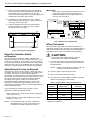
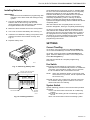
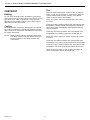
T8112C,D Electronic
Programmable Thermostats
INSTALLATION INSTRUCTIONS
Location
APPLICATION
The T8112C,D thermostats provide electronic
programmable control for 24 to 30 Vac heating and
cooling systems.
RECYCLING NOTICE
If this control is replacing a control that contains
mercury in a sealed tube, do not place your old
control in the trash.
Contact your local waste management authority
for instructions regarding recycling and the proper
disposal of the old thermostat.
INSTALLATION
Install the thermostat about 5 ft. (1.5m) above the floor in
an area with good air circulation at average temperature.
Do not install the thermostat where it can be affected by:
— drafts, or dead spots behind doors and in corners.
— hot or cold air from ducts.
— radiant heat from sun or appliances.
— concealed pipes and chimneys.
— unheated (uncooled) areas such as an outside wall
behind the thermostat.
Mounting Plate Installation
Position mounting plate on the wall. Use a level to make
sure mounting plate is level. Use a pencil to mark the two
mounting holes. See Fig. 1.
WALL ANCHORS (2)
When Installing this Product…
WIRES THROUGH
WALL OPENING
1. Read these instructions carefully. Failure to follow
them could cause a hazardous condition.
2. Check the ratings given in the instructions and on
the product to make sure the product is suitable for
your application.
3. Installer must be a trained experienced service
technician.
4. After installation is complete, check out product
operation as provided in these instructions.
WALL
MOUNTING
PLATE
CAUTION
MOUNTING
SCREWS (2)
1. Disconnect power supply to prevent electrical
shock or equipment damage.
2. After wiring is complete, push excess wire
back into the hole and plug hole with
nonhardening caulk, putty or insulation to
prevent drafts from affecting thermostat
operation.
®U.S. Registered Trademark
Copyright © 1998 Honeywell Inc. •
• All Rights Reserved
M1718
Fig. 1. Mounting plate installation.
X-XX UL
69-0917-2
T8112C,D ELECTRONIC PROGRAMMABLE THERMOSTATS
IMPORTANT
When using a high efficiency furnace such as a
90 percent or greater AFUE (Average Fuel
Utilization Efficiency) unit, adjust screw A out
one turn and screw B in.
1. Remove mounting plate from the wall, and drill
3/16 inch holes in wall (if drywall) as marked. For
firmer material such as plaster or wood, drill
7/32 inch holes. Gently tap anchors (provided) into
drilled holes until flush with the wall.
2. Reposition mounting plate over holes, pulling
wires through wiring opening. Loosely insert two
mounting screws into holes.
THERMOSTAT BACK
3. Level for appearance only; the thermostat will
function properly even when not level. Tighten
mounting screws. See Fig. 2.
A
C
B
D
W
FOR HIGH EFFICIENCY FURNACE (90%+ AFUE)
ADJUST: SCREW A–OUT 1 TURN
SCREW B–IN
FUEL SWITCH – F POSITION
LEVEL
ADJUST SCREWS THROUGH HOLES
TO SELECT OPERATION DESIRED
FUEL SWITCH
HEATING SYSTEM
POSITION
WARM AIR
B–IN
A–IN
F
FURNACE
HOT WATER A–OUT B–IN
F
1 TURN
BOILER
ELECTRIC
B–OUT
E
A–IN
FURNACE
1 TURN
FUEL SWITCH
E
F
Y
G
Rc
R
M3669
Fig. 3. Back view of thermostat.
Wiring Thermostat
All wiring must comply with local electrical codes and
ordinances. Refer to Fig. 4 through 7 for typical hookups. A
letter code is located near each terminal for identification.
See Table 1 for terminal cross referencing information.
M1714A
Fig. 2. Leveling mounting plate.
Adjust Fan Operation Switch,
as Required
CAUTION
Disconnect power before wiring to prevent
electrical shock or equipment damage.
The Thermostat fan operation switch, labeled FUEL
SWITCH is factory set in the F position. See Fig. 4. This
is the correct setting for most systems. If your system is
an electric heat system, set the switch to E. The E setting
allows the fan to turn on immediately with the heating or
cooling in a system where the G terminal is connected.
1. Connect the system wires to the thermostat. See
Fig. 8. A letter code is located near each terminal
for identification.
NOTE: Hold the thermostat as shown in Fig. 9 to
minimize need for wire extenders.
Adjust System On-time, as Required
The system on-time is factory-set for a warm air, gas or
oil heating system. If you are installing it on another type
of system, the system on-time must be adjusted
accordingly by setting screws A and B on the back of the
thermostat. Use the heating system table shown in Fig. 3
as a guide. The system on-time should be optimized
according to the type of system to minimize room
temperature swings. Setting the screw out one turn
means turning the screw approximately 360° or one
complete turn. Setting the screw in means tightening the
screw completely down.
2. Securely tighten each terminal screw.
3. Push excess wire back into the hole.
4. Plug hole with nonflammable insulation to prevent
drafts from affecting the thermostat.
Table 1. Typical Wire Colors and Functions
In the event that you want longer furnace on-time,
readjust the screws A and B as follows:
• Warm Air Furnace—set at the Hot Water setting (A—
out one turn, B—in).
• Electric Furnace—Leave at the Warm Air Furnace
setting (A—in, B—in).
Connect to
Wire Colora
G
Green
Fan
Y
Yellow
Cooling
Function
W
White
Heating
Rc
Blue
Air Cond. Power
R
Red
Furnace Power
a Wire colors are typical; verify at heating/cooling
equipment connection.
NOTE: This thermostat does not have a setting for
steam/gravity air. Cycles would not be long
enough for accurate temperature control.
69-0917—2
Thermostat
Terminal
2
T8112C,D ELECTRONIC PROGRAMMABLE THERMOSTATS
5-WIRE HEAT/COOL (JUMPER REMOVED)
2-WIRE HEAT-ONLY (JUMPER INTACT)
A
C
A
C
B
D
B
D
W
Y
JUMPER
G
W
Rc
R
HEATING
RELAY OR
VALVE COIL
Rc
FAN
RELAY
1
L2
1
G
R
HEATING
RELAY OR
VALVE COIL
L1
(HOT)
Y
POWER SUPPLY. PROVIDE DISCONNECT MEANS AND
OVERLOAD PROTECTION AS REQUIRED.
COOLING
CONTACTOR
COIL
1
1
L1
(HOT)
M1709B
L1
(HOT)
L2
Fig. 4. Typical hookup in two wire lead
only (jumper intact) application.
C
B
D
POWER SUPPLY. PROVIDE DISCONNECT MEANS AND
OVERLOAD PROTECTION AS REQUIRED.
M1711B
Fig. 6. Typical hookup in five wire heat
and cool (jumper removed) application.
4-WIRE HEAT/COOL (JUMPER INTACT)
A
L2
1
3-WIRE COOL-ONLY (JUMPER INTACT)
W
Y
G
JUMPER
R
A
C
B
D
Rc
W
Y
G
JUMPER
HEATING
RELAY OR
VALVE COIL
COOLING
CONTACTOR
COIL
R
FAN
RELAY
COOLING
CONTACTOR
COIL
L1
(HOT)
L2
1
Rc
FAN
RELAY
POWER SUPPLY. PROVIDE DISCONNECT MEANS AND
OVERLOAD PROTECTION AS REQUIRED.
M1710B
L1
(HOT)
L2
Fig. 5. Typical hookup in four wire heat
and cool (jumper intact) application.
1
POWER SUPPLY. PROVIDE DISCONNECT MEANS AND
OVERLOAD PROTECTION AS REQUIRED.
M848A
Fig. 7. Typical hookup in three wire cool
only (jumper intact) application.
3
69-0917—2
T8112C,D ELECTRONIC PROGRAMMABLE THERMOSTATS
T8112C
JUMPER (FACTORYINSTALLED) REMOVE
IF 5-WIRE SYSTEM
A. ENGAGE TABS AT TOP OF
THERMOSTAT AND MOUNTING PLATE.
B. PRESS LOWER EDGE
OF CASE TO LATCH.
Rc
R
5/16 in.
(8 mm)
STRIP
INSERT
STRAIGHT
UNDER
SCREW HEAD
AM
TU
LEAVE
W
Y
G
END OF WIRE
VISIBLE HERE
M1712A
Fig. 8. Proper wiring technique.
M5780
T8112D
A.
ENGAGE TABS AT TOP OF
THERMOSTAT AND MOUNTING PLATE.
B.
PRESS LOWER EDGE
OF CASE TO LATCH.
M3002A
Fig. 9. Holding thermostat while installing.
C.
Mounting Thermostat on Mounting Plate
SWING COVER OPEN TO
CHECK OPERATION.
1. Engage tabs at the top of thermostat and mounting
plate. See Fig. 10.
2. Press lower edge of case to latch.
NOTE: To remove the thermostat from the wall, first
pull out at the bottom of the thermostat; remove
top last.
M13063
Fig. 10. Mounting thermostat on mounting plate.
69-0917—2
4
T8112C,D ELECTRONIC PROGRAMMABLE THERMOSTATS
As the batteries are running low, a “bAt Lo” indicator flash
for one to two months before batteries run out completely.
Replace the batteries as soon as possible after the
indicator starts flashing. If the batteries are not replaced
sometime during the flashing “bAt Lo,” the indicator
eventually stops flashing. “bAt Lo” will stay on without
flashing, indicating the thermostat and heating/cooling
system have stopped working and the batteries are almost
completely dead.
Installing Batteries
IMPORTANT
Batteries must be installed for programming and
operation of the thermostat and heating/cooling
system.
1. Use two AA alkaline batteries; nonalkaline
batteries will not last as long, and can leak,
causing damage to the thermostat or wall surface.
Energizer batteries are recommended.
After the batteries are completely dead, the “bAt Lo”
indicator disappears, leaving a completely blank display.
2. Make sure the thermostat is set in the OFF position.
To remove, press down on left ends of batteries. If the
new batteries are installed within 20 to 30 seconds of
removing the old ones, the thermostat does not have to
be reprogrammed. If the display is blank, the batteries
are dead or incorrectly installed and the thermostat has
to be reprogrammed. See Owner’s Manual for
programming instructions.
3. Use a coin to remove the battery door. See Fig. 11.
4. Install the new batteries making sure positive and
negative terminals are oriented correctly. See
Fig. 12.
5. Replace battery door.
SETTINGS
Current Time/Day
To set time, press and release the Set Clock/Day key
once. Press the Time keys until the current time shows.
To set day, press and release the Set Clock/Day key
again. Press the Time keys until the current day shows.
Press Run Program key.
See Owner’s Manual for complete programming
instructions.
M5781
Fan Switch
FAN AUTO: Normal setting for most homes. A singlespeed fan turns on automatically with the air conditioner
of furnace. A two-speed fan usually runs on high with
the air conditioner and on low with the furnace.
Fig. 11. Removing battery door.
INSTALL TWO AA ALKALINE
BATTERIES AS SHOWN
NOTE: When Fan Operation Switch on the back of the
thermostat is in E position, the fan operates with
the furnace only.
AM
TU
LEAVE
FAN ON: The fan runs continuously. Used for improved
air circulation during special occasions or for more
efficient electronic air cleaning.
Fan
Auto On
System
System Switch
Cool Off Heat
FAN SWITCH
System switching positions control thermostat operation
as follows:
COOL: The thermostat controls the air conditioning
system.
OFF: Both the heating and air conditioning systems
are off.
HEAT: The thermostat controls the heating system.
SYSTEM
SWITCH
M5782
Fig. 12. Installing batteries.
5
69-0917—2
T8112C,D ELECTRONIC PROGRAMMABLE THERMOSTATS
CHECKOUT
Fan
Heating
Move the thermostat system switch to OFF and the fan
switch to ON. The fan should run continuously. With the
system switch still in the OFF position, move the fan
switch to AUTO; the fan should stop.
Do not check heating system operation by jumpering
thermostat terminals at the primary control such as the
gas valve, zone valve, or oil burner control This will
damage the thermostat. Instead, you could jumper R
and R wires at the thermostat.
Move the system switch to HEAT and the fan switch
to AUTO.
Press key until the setting is about 10°F (6°C) above room
temperature. Heating should start and the fan should run
after a short delay (immediately if fan operation switch is
set in E position).
Cooling
To avoid possible compressor damage, do not operate
the cooling system when outside temperature is below
50°F (10°C). See compressor manufacturer instructions
for further information.
Press key until setting is about 10°F (6°C) below room
temperature. The heating equipment should shut off.
NOTE: When cooling setting is changed, thermostat
can delay up to five minutes before turning on
the air conditioner. This delay protects the
compressor.
Move the system switch to COOL and the fan switch
to AUTO.
Press key until setting is about 10°F (6°C) below room
temperature. The cooling equipment and fan should start.
Press key until the setting is about 10°F (6°C) above room
temperature. The cooling equipment and fan should stop.
Move the system switch to OFF and the fan switch to
AUTO. The system and fan should be off.
69-0917—2
6
T8112C,D ELECTRONIC PROGRAMMABLE THERMOSTATS
TROUBLESHOOTING GUIDE
If…
Then…
Display will not come on.
• Set the system switch to OFF. Remove batteries. Insert batteries
backward for at least five seconds to reset thermostat. Correctly replace
batteries. Display should come on.
• Make sure batteries are fresh and installed correctly.
• Gently clean battery contacts using a soft pencil eraser. Do not use
anything abrasive on the clips.
Temperature display will not go lower
than 45° F (7° C) or higher than 88° F
(31° C) during programming.
• The temperature setting limit is reached. The setting range is 45° F to
88° F (7° C to 31°C).
Temperature change occurs at the
wrong times.
• Check the program times for the period in question. Be sure that AM and
PM indications are correct. Make sure the current day and time are
correct. Reprogram if necessary.
Heating will not come on.
• Check that switch on thermostat is set to HEAT. Allow a minimum of five
minutes for time guard protection to expire.
• Check the system fuse or circuit breaker and replace or reset if
necessary.
• Check for correct wiring and good connections.
• Disconnect and jumper wires R and W. If heat does not come on, check
out the heating system.
• If display is blank or says “bAt Lo,” install fresh batteries.
Cooling will not come on.
• Check that switch on thermostat is set to COOL. Allow a minimum of five
minutes for time guard protection to expire.
• Check the system fuse or circuit breaker and replace or reset if
necessary.
• Check for correct wiring and good connections.
• Disconnect and jumper wires R and Y. If cooling does not come on,
check out the cooling system.
• If display is blank or says “bAt Lo,” install fresh batteries.
• The thermostat has a built-in time delay on cooling. Allow at least five
minutes after changing the setting before the air conditioner starts.
• Make sure outdoor disconnect is engaged (on).
• If temperature setting is lower than current temperature, and SYSTEM
ON indicator is lit, move system switch from COOL to OFF for ten
minutes. After ten minutes, return switch to COOL position. If air
conditioner comes on, compressor could have reached its high limit
temperature protection and shut down.
• If 2- or 4-wire installation, verify that R-Rc jumper is installed
Too warm or too cool.
• Press Run Program key to check the current temperature setting.
• If desired, change the temperature setting. See the Owner’s Manual.
SYSTEM ON indicator is lit, but no heat
is coming from the registers.
• Allow time for the furnace to heat up and the fan to come on before
checking for heat at the register. (Check to make sure the Cycle Rate in
the Installation section is correct.)
Thermostat current temperature setting
does not match the display temperature
to within ± 1°.
• Check that the wiring hole in the wall behind the wallplate has been
plugged with insulation to prevent drafts that might adversely affect
thermostat operation.
• Be aware that it is normal for the current setting and display temperature
to differ on occasion.
• During recovery from setback or setup, setting and display temperatures
can differ for up to 30 minutes after recovery period.
bAtLo remains on display after batteries
are installed.
Remove batteries. Wait one hour. Install fresh Alkaline batteries.
NOTICE
This equipment is a Class B digital apparatus, which complies with Canadian Radio Interference Regulations, CRC
c.1374.
7
69-0917—2
T8112C,D ELECTRONIC PROGRAMMABLE THERMOSTATS
Home and Building Control
Honeywell Inc.
Honeywell Plaza
P.O. Box 524
Minneapolis, MN 55408-0524
69-0917—2 G.H. Rev. 4-98
Home and Building Control
Honeywell Limited-Honeywell Limitée
155 Gordon Baker Road
North York, Ontario
M2H 3N7
Printed in Mexico
8
www.honeywell.com