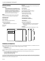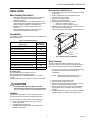
1
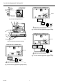
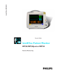
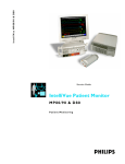
T8112D
Programmable Thermostat
PRODUCT DATA
FEATURES
• HEAT-OFF-COOL System switch.
• AUTO-ON Fan switch.
• Separate programs for weekdays and weekends
(5 day/2 day).
• Digital LCD display.
• Easy to program and install.
• Precise temperature control.
• Four daily energy saving programs.
GENERAL
The T8112D Programmable Thermostat provides energy
savings for single-stage heating and cooling applications
while providing reliable, precise temperature control.
• Compatible with most 24 Vac standing pilot, gas
electronic ignition, oil or central electric systems.
• Requires two AA alkaline batteries.
• LCD flashes bAt Lo indicating low battery power.
• Isolated heating/cooling circuits.
Contents
General ...............................................................................
Features ..............................................................................
Specifications ......................................................................
Ordering Information ...........................................................
Installation ...........................................................................
Programming the Thermostat .............................................
Checkout and Settings ........................................................
Troubleshooting ...................................................................
® U.S. Registered Trademark
Copyright © 1998 Honeywell Inc. • All Rights Reserved
1
1
2
2
3
6
7
8
68-0206
T8112D PROGRAMMABLE THERMOSTAT
Mounting:
Mounts on mounting plate directly on wall. Mounting screws
and wall anchors provided.
SPECIFICATIONS
IMPORTANT
The specifications given in this publication do not
include normal manufacturing tolerances; therefore,
an individual unit might not exactly match the listed
specifications. Also, this product is tested and
calibrated under closely controlled conditions, and
some minor differences in performance can be
expected if those conditions are changed.
Setpoint Range:
45°F to 88°F (7°C to 31°C).
Operating Ambient Temperature Range:
40°F to 110°F (4°C to 43°C).
Shipping Temperature Range:
-20°F to 120°F (-29°C to -49°C).
Model:
T8112D Thermostat: Provides electronic programmable
control for 24 to 30 Vac heating and cooling systems.
Temperature Display:
Fixed or field selectable.
Programming Keys:
Eight program keys.
Operating Relative Humidity:
5 to 90 percent RH; noncondensing.
Electrical Rating:
Battery operated (2 AA alkaline batteries).
Time Indication:
12 hour with AM, PM indication.
System and Fan Ratings:
1.2A run; 7.5A inrush.
Total cooling and fan load not to exceed 1.2A.
Cycles Per Hour Adjustment:
Heating: Field adjustable to 3, 6, or 9 cph ±10 percent.
Cooling: Factory set at 3 cph ±10 percent (not field
adjustable).
Dimensions:
See Fig. 1.
Calibration:
Thermostat and thermometer self-calibrating to ±1.25°F.
1(25)
6-7/8 (175)
4
(102)
3/4 (19)
1-1/4
(32)
M9349
Fig. 1. T8112 dimensions in in. (mm).
ORDERING INFORMATION
When purchasing replacement and modernization products from your TRADELINE® wholesaler or your distributor, refer to the
TRADELINE® Catalog or price sheets for complete ordering information, or specify:
1. Model Number.
2. Accessories, as desired.
If you have additional questions, need further information, or would like to comment on our products or services, please write or
phone:
1. Your local Honeywell Home and Building Control Sales Office (check white pages of phone directory).
2. Home and Building Control Customer Relations
Honeywell, 1885 Douglas Drive North
Minneapolis, Minnesota 55422-4386
In Canada—Honeywell Limited/Honeywell Limitée, 35 Dynamic Drive, Scarborough, Ontario M1V 4Z9. International Sales and
Service offices in all principal cities of the world. Manufacturing in Australia, Canada, Finland, France, Germany, Japan, Mexico,
Netherlands, Spain, Taiwan, United Kingdom, U.S.A.
68-0206
2
T8112D PROGRAMMABLE THERMOSTAT
INSTALLATION
Mounting Plate Installation (Fig. 2)
1. Hold mounting plate in position and mark the two holes
for mounting.
2. Level for appearance only; thermostat functions
properly even when not level.
3. Tighten the mounting screws.
4. Set aside the mounting plate.
5. Drill the two holes in the wall as marked.
— Drill 3/16 in. holes for drywall.
— Drill 7/32 in. holes for plaster or wood.
6. Reposition the mounting plate over the holes and pull
wires through the wiring opening.
7. Loosely insert the two mounting screws into the holes.
When Installing this Product…
1. Read these instructions carefully. Failure to follow the
instructions can damage the product or cause a
hazardous condition.
2. Check the ratings given in the instructions and on the
product and in the compatibility chart (Table 1) to make
sure the product is suitable for your application.
3. Installer must be a trained, experienced service
technician.
4. After installation is complete, check out product
operation as provided in these instructions.
Compatibility
WALL ANCHORS (2)
WIRES THROUGH
WALL OPENING
Check Table 1 to make sure the thermostat is compatible with
the intended system.
WALL
Table 1. Compatibility Chart.
System Type
Compatible
with T8112D
Gas—Standing Pilot
Yes
Gas—Electronic Ignition
Yes
Gas-Fired Boilers
Yes a
Gas— Millivolt
MOUNTING
PLATE
MOUNTING
SCREWS (2)
No
Oil-Fired Boilers
Yes a
Oil-Fired Furnace
Yes
Electric Furnace
Yes
Electric Air Conditioning
Yes
Baseboard Electric (120/240 Line Volt)
No
Heat pumps/Multistage Equipment
No
M1718
Fig. 2. Mounting plate installation.
Wiring Thermostat
All wiring must comply with local electrical codes and
ordinances. Refer to Fig. 5 through 8 for typical hookups. A
letter code is located near each terminal for identification.
1. Connect the system wires to the thermostat. See Fig. 3.
A letter code is located near each terminal for
identification.
a
Compatible with 2-wire Honeywell zone valves.
All system types:
Not compatible with any 120/240 volt circuit.
Not designed for steam or gravity systems.
Not compatible with 2-wire White Rodgers no. 1361 zone
valves.
Isolating relay required for 3-wire thermostats for zone valves.
NOTE: Hold the thermostat as shown in Fig. 4 to
minimize the need for wire extenders.
2. Securely tighten each terminal screw.
3. Push excess wire back into the hole.
4. Plug the hole with nonflammable insulation to prevent
drafts from affecting thermostat operation.
5. Run the required number of wires to the thermostat
location. Refer to Fig. 5 through 8 for typical wiring
diagrams.
6. In 5-wire installations only, be sure to remove the factoryinstalled jumper connecting the terminals R and Rc.
CAUTION
Damage to Heating Cooling System Possible.
Be careful when handling wires during installation.
Disconnect power at furnace or main breaker/fuse box.
Location
Locate the thermostat about 5 ft (1.5m) above the floor in
an area with good air circulation at average temperature.
Do not mount the thermostat where it can be affected by:
— drafts or dead spots behind doors and in corners.
— hot or cold air ducts.
— concealed pipes and chimneys.
— unheated (uncooled) areas such as an outside wall
behind the thermostat.
3
68-0206
T8112D PROGRAMMABLE THERMOSTAT
Rc
R
5/16 in.
(8 mm)
STRIP
3-WIRE COOL-ONLY (JUMPER INTACT)
JUMPER (FACTORYINSTALLED) REMOVE
IF 5-WIRE SYSTEM
INSERT
STRAIGHT
UNDER
SCREW HEAD
A
C
B
D
W
Y
G
JUMPER
Rc
R
W
Y
END OF WIRE
VISIBLE HERE
G
M1712A
Fig. 3. Proper wiring technique.
COOLING
CONTACTOR
COIL
FAN
RELAY
L1
(HOT)
L2
1
POWER SUPPLY. PROVIDE DISCONNECT MEANS AND
OVERLOAD PROTECTION AS REQUIRED.
M848A
Fig. 6. 3-wire cool-only application (jumper intact).
4-WIRE HEAT/COOL (JUMPER INTACT)
A
C
B
D
W
Y
G
JUMPER
M3002A
Fig. 4. Holding thermostat while installing.
R
2-WIRE HEAT-ONLY (JUMPER INTACT)
A
C
B
D
W
Y
HEATING
RELAY OR
VALVE COIL
COOLING
CONTACTOR
COIL
FAN
RELAY
JUMPER
G
Rc
L1
(HOT)
L2
1
Rc
R
POWER SUPPLY. PROVIDE DISCONNECT MEANS AND
OVERLOAD PROTECTION AS REQUIRED.
M1710B
Fig. 7. 4-wire heat/cool application (jumper intact).
HEATING
RELAY OR
VALVE COIL
L1
(HOT)
1
L2
1
POWER SUPPLY. PROVIDE DISCONNECT MEANS AND
OVERLOAD PROTECTION AS REQUIRED.
M1709B
Fig. 5. 2-wire heat-only application (jumper intact).
68-0206
4
T8112D PROGRAMMABLE THERMOSTAT
5-WIRE HEAT/COOL (JUMPER REMOVED)
A
C
B
D
W
Y
G
HEATING
RELAY OR
VALVE COIL
FAN
RELAY
COOLING
CONTACTOR
COIL
1
NOTE:
For condensing furnaces, follow manufacturer
instructions.
If you want a longer on-time, readjust screws A and B as
follows (refer to Table 1 Compatibility Chart):
•
Warm Air Furnace—set at the Hot Water setting (A—out
one turn, B—in).
•
Electric Furnace—leave at the Warm Air Furnace setting
(A—in, B—in).
1
L1
(HOT)
L1
(HOT)
L2
L2
1
This thermostat does not have a setting for steam/
gravity air. Cycles would not be long enough for
accurate temperature control.
IMPORTANT
When using a high efficiency furnace such as a
90 percent or greater AFUE (Average Fuel Utilization
Efficiency) unit, adjust screw A out one turn and
screw B In one turn.
Rc
R
NOTE:
NOTE: This thermostat does not have a setting for steam/
gravity air. Cycles would not be long enough for
accurate temperature control.
POWER SUPPLY. PROVIDE DISCONNECT MEANS AND
OVERLOAD PROTECTION AS REQUIRED.
M1711B
Fig. 8. 5-wire heat/cool application (jumper removed).
Install Batteries
Adjust Fan Operation Switch, as Required
IMPORTANT
Batteries must be installed for programming and
operating the thermostat and heating/cooling
system.
The thermostat fan operation switch, labeled FUEL SWITCH
(see Fig. 9) is factory set in the F position. This is the correct
setting for most systems. If you have an electric heat system,
set the switch to E. In systems with the G terminal connected,
the E setting turns on the fan immediately with heating or
cooling.
1. Use two AA alkaline batteries; nonalkaline batteries will
not last as long.
2. Make sure the thermostat is set to the Off position.
3. Use a coin to remove the battery door (see Fig. 10).
4. Install the new batteries as shown, making sure positive
and negative terminals are oriented correctly (see Fig. 11).
5. Replace the battery door.
THERMOSTAT BACK
A
C
B
D
FOR HIGH EFFICIENCY FURNACE (90%+ AFUE)
ADJUST: SCREW A–OUT 1 TURN
SCREW B–IN
FUEL SWITCH – F POSITION
FUEL SWITCH
E
F
ADJUST SCREWS THROUGH HOLES
TO SELECT OPERATION DESIRED
FUEL SWITCH
HEATING SYSTEM
POSITION
WARM AIR
A–IN
B–IN
F
FURNACE
HOT WATER A–OUT B–IN
F
1
TURN
BOILER
ELECTRIC
B–OUT
E
A–IN
FURNACE
1 TURN
W
Y
R
When the batteries are running low, a bAt Lo indicator will
flash for one to two months before batteries run out
completely. Replace the batteries as soon as possible after
the indicator starts flashing. If the batteries are not replaced
when the bAt Lo indicator is flashing, the indicator eventually
stops flashing. When the batteries are almost completely
dead, bAt Lo will stay on without flashing, indicating that the
thermostat and heating/cooling system have stopped working.
The thermostat will not function after the batteries are
completely dead, and the bAt Lo indicator disappears, leaving
a completely blank display.
G
Rc
M3669
Fig. 9. Back view of thermostat.
To remove the batteries, press down on the left ends. When
the new batteries are installed within 20 to 30 seconds of
removing the old ones, the thermostat does not have to be
reprogrammed. If the display is blank, the batteries are dead
or incorrectly installed and the thermostat has to be
reprogrammed. See Owner’s Manual for reprogramming
instructions.
Adjust System On-Time as Required
The thermostat on-time is factory set for a warm air, gas or oil
heating system. If you are installing it on another type of
system, the system on-time must be adjusted by changing the
setting of screws A and B on the back of the thermostat. Use
the heating system table in Fig. 9 as a guide to minimize room
temperature swings. The system on-time should be optimized
according to the type of system. Setting the screw out one
turn means turning the screw approximately 360°, or one
complete turn.
IMPORTANT
Although the thermostat has a low battery indicator,
replace the batteries once a year to prevent the
thermostat from losing time and programming due to
lack of battery power.
5
68-0206
T8112D PROGRAMMABLE THERMOSTAT
PROGRAMMING THE THERMOSTAT
Set the Current Time/Day
To set the time:
1. Press and release the Clock/Day key once.
2. Press the Time keys ▲ or ▼ until the current time
displays.
To set the day:
1. Press and release the Clock/Day key again.
2. Press the Time keys ▲ or ▼ until the current day
displays.
3. Press the Run Program key.
M5781
Fig. 10. Removing battery door.
INSTALL TWO AA ALKALINE
BATTERIES AS SHOWN
Heating Program
To set the system switch to HEAT:
AM
TU
Fan
1. Press and release the Schedule key once. WAKE,
Mon-Fri , and SET appear on the display.
2. Press the Time keys ▲ or ▼ to program WAKE time,
and Temp keys ▲ or ▼ to program WAKE temperature
for Mon-Fri.
3. Repeat this sequence for LEAVE, RETURN, and
SLEEP.
4. Press the Schedule key until SAT, SUN, WAKE and
SET appear on the display.
5. Press the Time keys ▲ or ▼ to program WAKE time,
and Temp ▲ or ▼ to program WAKE temperature for
Sat-Sun.
6. Repeat this sequence for SLEEP.
LEAVE
Auto On
System
Cool Off Heat
FAN SWITCH
SYSTEM
SWITCH
M5782
Fig. 11. Installing batteries.
Mounting Thermostat
Cooling Program
1. Engage the tabs at the top of the thermostat and
mounting plate. See Fig. 12.
2. Press the lower edge of the case to latch.
1. Set the system switch to COOL and follow the same
procedure as for the Heating Program.
2. After programming, adjust the fan and system switches
as desired.
3. Press and release the Run Program key to start the
program.
NOTE: To remove the thermostat from the wall, first pull out
the bottom of the thermostat and then remove the
top portion.
A. ENGAGE TABS AT TOP OF
THERMOSTAT AND MOUNTING PLATE.
A Quick Guide for Operating or Making
Changes
B. PRESS LOWER EDGE
OF CASE TO LATCH.
NOTE:
AM
TU
LEAVE
The system switch must be set to Heat or Cool to
perform the following.
To temporarily change the temperature for the
current period only:
1. Press the Temp keys ▲ or ▼.
— The temporary indicator shows on the display and
cancels itself at the next scheduled change.
2. To cancel sooner, press the Run Program key.
To hold a temperature indefinitely:
M5780
1. Press the Hold Temp key.
2. Press the Temp keys ▲ or ▼.
3. To cancel, press the Run Program key.
Fig. 12. Mounting thermostat on mounting plate.
68-0206
6
T8112D PROGRAMMABLE THERMOSTAT
To check the current temperature setting:
Fan Switch
Press the Run Program key. (When using TEMPORARILY
CHANGE or HOLD, pressing this key will cancel the change
or hold.)
FAN AUTO: Normal setting for most homes. A
single-speed fan turns on automatically with
the air conditioner or furnace. A two-speed fan
usually runs on high with the air conditioner
and on low with the furnace.
FAN ON: The fan runs continuously. Use for
improved air circulation during special
occasions or for more efficient electronic air
cleaning.
To check the programs:
1. Press the Schedule key repeatedly to see each time
and temperature.
2. Press the Run Program key.
To cancel a program:
Auto
On
M1705
Auto
On
M1706
System Switch
1. Press the Schedule key until the program to cancel
appears
2. Press both the Time keys ▲ and ▼ together.
COOL: The thermostat controls the air
conditioning system.
Cool
Off
Heat
M1704
To permanently change a program:
OFF: Both the heating and air conditioning
systems are off.
Repeat the steps in the Heating Program or Cooling Program
section as applicable.
Cool
Off
Heat
M1707
To return to the normal program:
HEAT: The thermostat controls the heating
system.
Press the Run Program key.
Cool
Off
Heat
M1703
CHECKOUT AND SETTINGS
After the thermostat is mounted on the mounting plate, check operation as follows:
Heating
Cool
Off
Heat
Do not check the heating system operation by jumpering the thermostat terminals at the primary control
such as the gas valve, zone valve, or oil burner control. This will damage the thermostat.
M1703
Auto
On
Move the system switch to HEAT and the fan switch to AUTO.
M1705
Press the TEMP key until the setting is about 10°F (6°C) above the room temperature. After a short
delay, the heating should start and the fan should run (immediately if fan operation switch is set in
E position).
Temp
Press the TEMP key until the setting is about 10°F (6°C) below the room temperature. The heating
equipment should shut off.
Temp
Cool
Cooling
Off
Heat
To avoid possible compressor damage, do not operate the cooling system when the outside temperature
is below 50°F (10°C). See the compressor manufacturer instructions for further information.
M1704
NOTE: When the cooling setting is changed, the thermostat can delay up to five minutes before turning
on the air conditioner to protect the compressor.
Auto
Move the system switch to COOL and the fan switch to AUTO.
On
M1705
Press the TEMP key until the setting is about 10°F (6°C) below room temperature. The cooling
equipment and fan should start.
Temp
Press the TEMP key until the setting is about 10°F (6°C) above the room temperature. The cooling
equipment and fan should stop.
Temp
Move the system switch to OFF with the fan switch remaining at AUTO. The system and fan should be
off.
Cool
Off
Heat
M1707
Auto
On
M1705
7
68-0206
T8112D PROGRAMMABLE THERMOSTAT
Minimum Off-Timer
If the compressor turns off when the setpoint is changed, then
the minimum-off timer is triggered, which operates only during
the cooling cycle of the T8112D.
A minimum off-timer for the T8112D assures that the cooling
compressor does not come on again for at least five minutes
after it turns off. The minimum-off timer is triggered when the
compressor turns off and when the system switch is changed.
TROUBLESHOOTING
IF…
Display will not come on.
Temperature display will not go lower
than 45°F (7°C) or higher than 88°F
(31°C) during programming.
Heating will not come on.
Cooling will not come on.
THEN…
• Set the system switch to OFF; remove batteries; insert backward for at least
five seconds to reset thermostat; replace batteries correctly. Display should come
on.
• Make sure batteries are fresh and installed correctly.
• The temperature setting limit has been reached. The setting range is 45°F to 88°F
(7°C to 31°C).
•
•
•
•
•
•
•
•
•
•
SYSTEM ON indicator is lit, but no
heat is coming from the registers.
•
Furnace or air conditioner cycles too
frequently.
The system on-time is too short or too
long.
The thermostat current setting does
not match the display temperature.
•
bAt Lo remains on the display after
fresh batteries have been installed.
Home and Building Control
Honeywell Inc.
1985 Douglas Drive North
Golden Valley, MN 55422
68-0206 L.C. 2-98
Printed in U.S.A.
If the display is blank or displays bAt Lo, install fresh batteries.
Check that the switch on the thermostat is set to HEAT.
Check the system fuse or circuit breaker and replace or reset if necessary.
If the temperature setting is higher than the current temperature, and SYSTEM ON
indicator is lit, see the furnace manufacturer instructions.
If the display is blank or displays bAt Lo, install fresh batteries.
In 2- or 4-wire installations, verify that the R-Rc jumper is installed.
Check that the switch on the thermostat is set to COOL.
Check the system fuse or circuit breaker and replace or reset if necessary.
The thermostat has a built-in time delay on cooling. Allow five to ten minutes after
changing the setting before the air conditioner starts.
If the temperature setting is lower than the current temperature, and the SYSTEM
ON indicator is lit, see the air conditioner manufacturer instructions.
Allow time for the furnace to heat up and the fan to come on before checking for
heat at the register. Check to make sure system on-time is set correctly according
to the instructions in the Installation section.
Readjust according to the instructions in the Installation Section.
• Readjust according to the instructions in the Installation Section.
• Check that the wiring hole in the wall behind the wallplate was plugged with
insulation to prevent drafts that could adversely affect thermostat operation.
• It is normal for the current setting and display temperature to differ occasionally.
• Remove batteries. Wait one hour. Install fresh alkaline batteries.
Home and Building Control
Honeywell Limited-Honeywell Limitée
155 Gordon Baker Road
North York, Ontario
M2H 3N7
8
Printed on recycled paper containing at
least 10% post-consumer paper fibers.
www.honeywell.com/yourhome