1
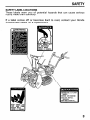
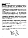
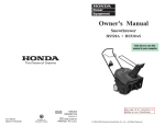
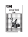
Owner's Manual
SNOWBLOWER
HS622
©1996 Honda Motor Co., Ltd.—All Rights Reserved
The engine exhaust from this product
contains chemicals known to the State
of California to cause cancer, birth
defects or other reproductive harm.
1
Thank you for purchasing
a Honda snowblower.
We want to help you
get the best results from your new snowblower
and to operate it
safely. This manual contains the information
on how to do that;
please read it carefully.
This owner’s manual describes the operation
and maintenance
of
HONDA snowblower:
HS622
All information
in this publication
is based on the latest product
information
available at the time of printing.
Honda Motor Co., Ltd. reserves the right to make changes at any time
without notice and without incurring any obligation.
No part of this publication
may be reproduced
without
written
permission.
This manual
should
be considered
a permanent
part of the
snowblower
and should remain with it if it is resold.
Safety Messages
Your safety and the safety of others is very important.
We have
provided
important
safety messages
in this manual and on the
snowblower.
Please read these messages carefully.
A safety message alerts you to potential hazards that could hurt you
or others. Each safety message is preceded by a safety alert symbol
8. and one of three words: DANGER, WARNING, or CAUTION.
These mean
m
You WILL be KILLED or SERIOUSLY
follow instructions.
HURT if you don’t
B
You CAN be KILLED or SERIOUSLY
follow instructions.
B
HURT if you don’t
You CAN be HURT if you don’t follow instructions.
Each message tells you what the hazard
what you can do to avoid or reduce injury.
Damage Prevention Messages
You will also see other important
word NOTICE.
messages
is, what
can happen,
that are preceded
and
by the
This word means:
(
Your snowblower
or other property
you don’t follow instructions.
The purpose
snowblower,
could be damaged
of these messages is to help prevent
other property, or the environment.
damage
if
to your
CONTENTS
3
SAFETY ........................................................................................................
3
..................................................................
SAFETY LABEL LOCATIONS
4
..........................................................................
SAFETY INFORMATION
.7
COMPONENT IDENTIFICATION.. ..............................................................
8
..................................................................................................
CONTROLS
8
Engine Switch ..........................................................................................
8
.................................................................................................
Fuel Valve
9
..............................................................................................
Choke Lever
9
...............................................................................................
Starter Grip
.lO
........................................................................................
Throttle Lever
10
Shift Lever ..............................................................................................
11
...........................................................................................
Chute Guide
................................................................................
.ll
Drive Clutch Lever
12
Auger Clutch Lever ................................................................................
........................................................................
.12
Height Adjustment
Bolt
13
Skid Plate and Scraper ..........................................................................
Handle Height Adjusting
Bolt ...............................................................
::
PRE-OPERATION CHECK.. ........................................................................
14
Engine Oil ...............................................................................................
15
Fuel .........................................................................................................
18
Auger Bolts .............................................................................................
18
Other Checks ..........................................................................................
19
STARTING THE ENGINE ...........................................................................
22
SNOWBLOWER OPERATION ...................................................................
22
Operating the Controls ..........................................................................
26
Clearing Snow ........................................................................................
28
High Altitude Operation ........................................................................
-29
STOPPING THE ENGINE ..........................................................................
30
MAINTENANCE .........................................................................................
30
..........................................................
The Importance of Maintenance
31
Maintenance
Safety ...............................................................................
.32
Proper Maintenance
is the Owner’s Responsibility
..........................
33
Maintenance
Schedule ..........................................................................
34
.......................................................................................................
Tools
................................................................................
.35
Engine Oil Change
36
Spark Plug Service .................................................................................
38
...................................................................................
Track Adjustment
39
...............................................................
Inspection
Auger and Blower
40
...................................................................................................
STORAGE
.
TROUBLESHOOTING..
SPECIFICATIONS.. .............................................................................................................
.46
WARRANTY SERVICE INFORMATION ...................................................
47
.........................................................................................................
INDEX
2
SAFETY
SAFETY LABEL LOCATIONS
These labels warn you of potential
injury. Read them carefully.
hazards
that
can cause
If a label comes off or becomes hard to read, contact
Snowblower
dealer for a replacement.
your
serious
Honda
3
SAFETY INFORMATION
Most accidents with snowblowers can be prevented if you follow all
instructions
in this manual and on the snowblower.
The most
common hazards are discussed below, along with the best way to
protect yourself and others.
Always make a pre-operation check (pages 14 thru 18 ) before you
start the engine. You may prevent an accident or equipment
damage.
Honda snowblowers
are designed to give safe and dependable
service if operated according to instructions. Read and understand
this Owner’s Manual before operating the snowblower.
Failure to
do so could result in personal injury or equipment damage.
Before operating the snowblower, inspect the area in which you are
going to clear snow. Remove debris and other obstacles the
snowblower
might strike or throw as that may cause injury or
damage to the snowblower.
Inspect the snowblower before operating it. Repair any damage and
correct any malfunction before operation.
If you hit an obstacle while operating the snowblower,
stop the
engine immediately,
and check for damage. Damaged equipment
may increase the possibility of injury during operation.
Do not use the snowblower
when visibility
is poor. Under
conditions of poor visibility, there is a greater risk of striking an
obstacle or causing injury.
Never use the snowblower
to clear snow from a gravel road or
driveway, as rocks may be picked up and ejected. They may cause
iniurv to bvstanders.
l
l
l
l
l
l
Adjust the snow discharge chute to avoid hitting the operator,
bystanders, windows, and other objects with ejected snow. Stay
clear of the snow discharge chute while the engine is running.
Children and pets must be kept away from the area of operation
avoid injury from flying debris and contact with the snowblower.
to
To avoid overturning, be careful when changing the direction of the
snowblower while operating it on a slope.
Do not use the snowblower
to remove snow from roofs. The
snowblower
may overturn on steep slopes if left unattended,
causing injury to the operator or bystanders.
Know how to stop the snowblower
operation of all controls.
quickly,
and understand
the
Never permit anyone to operate the snowblower without proper
instruction.
If people or pets suddenly appear in front of the
snowblower while it is in operation, immediately release the auger
and drive clutch levers to stop the snowblower and avoid possible
injury from rotating auger blades.
If the snow discharge chute becomes clogged, stop the engine and
use a wooden stick to unclog it. Never put your hand into the snow
discharge chute while the engine is running; serious personal injury
could result.
5
l
l
l
l
l
Gasoline is extremely
conditions.
flammable
certain
Do not overfill the fuel tank, and make sure the filler cap is closed
securely after refueling.
Never run the engine in an enclosed or confined area. Exhaust
contains poisonous carbon monoxide gas; exposure can cause loss
of consciousness and may lead to death.
The muffler becomes very hot during operation
after stopping
muffler while it is hot.
snowblower indoors.
6
under
Do not smoke or allow flames or sparks where the snowblower is
refueled or where gasoline is stored. Allow the engine to cool down
before refueling.
Refuel in a well-ventilated
area with the engine stopped.
a while
l
and is explosive
the engine.
Let the
and remains hot for
Be careful not to touch
engine
cool before
storing
the
the
While operating the snowblower, hold the handle firmly, and walk,
don’t run. Wear suitable winter boots that resist slipping.
COMPONENT
IDENTIFICATION
ENGINE SWITCH
AUG/ER CLUTCH LEVER
SNOW
CHUTE
SHIFT LEVER
CHUTE GUIDE
/
FUEL VALVE
STARTER GRIP
OIL FILLER CAP
Record the frame and engine serial numbers for your reference. Refer
to the serial numbers when ordering parts, and when making technical
or warranty inquiries (see page 47 ).
Frame serial number:
Engine serial number:
7
CONTROLS
Engine Switch
Use the engine switch
to STOP the engine.
to turn the ignition
system
ON for starting,
and
ENGINE SWITCH
Fuel Valve
The fuel valve opens and closes the fuel line leading from the fuel tank
to the carburetor.
Make sure that the valve is positioned
exactly at
either the ON or OFF position. When the snowblower
is not in use,
always leave the fuel valve in the OFF position to reduce the possibility
of fuel leakage.
FUEL VALVE
If the snowblower
is to be transported
sure
fuel
to turn
carburetor
8
the
flooding
valve
to the
from one location
OFF
position.
and reduce the possibility
This
to another,
will
of fuel leakage.
be
prevent
Choke Lever
Close the choke when the engine
is cold or difficult
to start.
Starter Grip
See page 19 for starting procedures.
Pull this grip to start the engine.
STARTER GRIP
/
9
Throttle Lever
Use the throttle lever to select engine
the “FAST” position.
speed. In normal
THROlTLE
operation,
LEVER
Shift Lever
Use the shift lever to select drive speed or direction.
(1):
(2):
(3):
(4):
LOW SPEED
HIGH SPEED
NEUTRAL
REVERSE
SHIFT LEVER
1: LOW SPEED
N: NEUTRAL
2: HIGH SPEED
10
use
Chute Guide
The chute guide controls
the snow discharge
angle and direction.
CHUTE GUIDE
CHUTE GUIDE
Drive Clutch Lever
Use the drive clutch
lever to propel or stop the snowblower.
DRIVE CLUTCH LEVER
11
Auger Clutch Lever
Squeezing the auger clutch lever also operates the drive clutch lever;
the snowblowing
mechanism
starts and the snowblower
moves
forward. Releasing the auger clutch lever stops both the snowblowing
mechanism and the forward motion of the snowblower.
STOP
Height Adjustment
AUGER CLUTCH LEVER
Bolt
Use the bolt for adjusting
relation to the tracks.
Raise or lower the machine
the
height
to the desired
: Hard snow or fine finish
LOW
MIDDLE : Normal use
: Deep snow or for transporting
HIGH
and angle
of the machine
position.
(See page 22 1
the snowblower.
HEIGHT ADJUSTMENT
12
BOLT
in
Skid Plate and Scraper
Adjust the skid plates and scraper for the auger housing
ground
clearance best suited to your snow removal conditions.
(See page 22 )
/
SCRAPER
Handle Height Adjusting
Bolt
The handlebars
can be set in the high, low or middle position to suit
the operator. To change handlebar height, remove the right and left
adjusting bolts, align the bolt holes for the desired handlebar height,
and reinstall the bolts. Tighten the nuts securely.
HANDLE HEIGHT
ADJUSTING BOLT
13
Engine Oil
Inspection
With the snowblower
on a level surface, remove the oil filler cap and
wipe the dipstick clean. Insert the dipstick into the filler neck, but do
not screw it in. Remove the dipstick and check the oil level.
If the level is low,
ret :ommended oil.
fill
to the
top
of the
oil
filler
neck
with
the
OIL FILLER NECK
OIL FILLER CAP AND DIPSTICK
-20
-30
0
-20
Oil capacity:
40
20
-10
0
50°F
10°C
0.60 !J (0.63 US qt ,0.53 Imp qt)
Recommended oil
Use 4-stroke motor oil that meets or exceeds the requirements
for API
service classification
SF or SG. Always check the API SERVICE label on
the oil container to be sure it includes the letters SF or SG.
SAE 5W-30 is recommended
for general use. Other viscosities
shown
in the chart may be used when the average temperature
in your area is
within the indicated range.
(NOTlCEI
l
l
Using nondetergent
oil can shorten the engine’s
using P-stroke oil can damage the engine.
service life, and
Running the engine with a low oil level can cause engine damage.
14
Fuel
Refueling
Fuel tank capacity:
3.5 0 (0.92 US gal, 0.77 Imp gal)
Check the fuel level gauge, and refill the tank if the fuel level is low.
Gasoline is highly flammable
and explosive.
You can be burned or seriously injured when handling fuel.
l
l
l
Stop the engine and keep heat, sparks, and flames away.
Handle fuel only outdoors.
Wipe up spills immediately.
Refuel in a well-ventilated
area before starting the engine. If the engine
has been running, allow it to cool. Refuel carefully to avoid spilling fuel.
Do not overfill: there should be no fuel in the filler neck. After refueling,
tighten the fuel tank cap securely.
Never refuel the snowblower
inside a building where gasoline fumes
may reach flames or sparks. Keep gasoline away from appliance pilot
lights, barbeques, electric appliances, power tools, etc.
Spilled fuel is not only a fire hazard, it causes environmental
Wipe up spills immediately.
damage.
1 NOTICE 1
Fuel can damage paint and plastic. Be careful not to spill fuel when
filling your fuel tank. Damage caused by spilled fuel is not covered
under warranty.
FILLER NECK
UPPER LIMIT
GAUGE
-FUEL
-
15
Fuel Recommendations
Use unleaded gasoline with a pump octane rating of 86 or higher.
This engine is desi ned to operate on unleaded gasoline. Unleaded
gasoline produces Pewer engine and spark plug deposits and extends
exhaust system life.
Never use stale or contaminated
gasoline
Avoid getting dirt or water in the fuel tank.
or an oil/gasoline
mixture.
hear a light “spark
knock”
or “pinging”
Occasionally
you ma
(metallic rapping noise Y while operating under heavy loads. This is no
cause for concern.
If spark knock or pin ing occurs at a steady engine speed, under
If spark knock or pinging
normal load, than e %rands of gasoline.
persists, see an aut Rorized Honda servicing dealer.
Running the engine with persistent spark knock or pinging can cause
engine damage.
Running the engine
and the Distributor’s
by misuse.
16
with persistent spark knock or pinging is misuse,
Limited Warranty does not cover parts damaged
Oxygenated
Fuels
Some conventional gasolines are being blended with alcohol or an
ether compound. These gasolines are collectively referred to as
oxygenated fuels. To meet clean air standards, some areas of the
United States and Canada use oxygenated fuels to help reduce
emissions.
If you use an oxygenated
fuel, be sure it is unleaded
minimum octane rating requirement.
and meets the
Before using an oxygenated
fuel, try to confirm the fuel’s contents.
Some states/provinces
require this information
to be posted on the
pump.
The following
are the EPA-approved
percentages
of oxygenates:
ETHANOL -
(ethyl or grain alcohol) 10% by volume
You may use asoline containing
up to 10% ethanol
by volume.
ethanol
may be
8 asoline containing
marketed under the name “Gasohol”.
MTBE
(Methyl Tertiary Butyl Ether) 15% by volume
You may use gasoline containing
up to 15% MTBE
by volume.
METHANOL ~
(methyl or wood alcohol) 5% by volume
You may use gasoline
containing
up to 5%
methanol
by volume, as long as it also contains
cosolvents
and corrosion
inhrbitors
to protect the
fuel system.
Gasoline
containing
more than 5%
methanol
by volume
may cause starting
and/or
performance
problems. It may also damage metal,
rubber, and plastic parts of your fuel system.
If you notice any undesirable
station, or switch to another
operating symptoms,
brand of gasoline.
try another
service
Fuel system damage or performance
problems resulting from the use
of an oxygenated
fuel containing
more than the percentages
of
oxygenates
mentioned above are not covered under warranty.
17
Auger Bolts
Check the auger for loose or broken bol,ts. If broken,
new ones (page 39 ).
replace them with
NUT
AUGER SHEAR BOLT
Other Checks
1. Check all bolts, nuts and other fasteners
for security.
2. Check each part for operation.
3.Check the entire machine for any other
been caused in previous operation.
18
faults
which
might
have
STARTING THE ENGINE
Never run the engine in an enclosed or confined .area. Exhaust
contains poisonous carbon monoxide gas; exposure can cause loss of
consciousness and may lead to death.
1. Turn the engine switch to the ON position.
ENGIN,E SWITCH
2. Turn the fuel valve to the ON position.
Be sure that the drain knob is tightened
securely.
FUEL VALVE
DRAIN KNOB
19
3. In cold weather and when the engine
CLOSE position.
is cold, move the choke to the
CHOKE LEVER
4. Pull the starter grip lightly
until you feel resistance,
then pull briskly.
[I
l
l
Do not allow the starter grip to snap back against the engine.
Return it gently to prevent damage to the starter.
Damage may result if the starter grip is pulled while the engine is
running.
STARTER GRIP
20
5. Let the engine warm up for several minutes. If the choke has been
moved to the CLOSE position, gradually move the choke lever to the
OPEN position as the engine warms up.
CHOKE LEVER
--T----
I
21
SNOWBLOWER
OPERATION
Operating the Controls
1. Adjust the skid plate and scraper
and the spark plug cap removed.
positions
with the engine
stopped
The skid plate and scraper have three adjusting positions.
Select the
position according to the surface conditions
described in the chart.
NOTE:
Adjust the height
After adjusting
nuts securely.
equally
the height,
on both sides.
be sure to tighen
the adjusting
bolts
and
TO RAISE
HEIGHT ADJUSTING
HtltiH
Operation
Regular work
Clearing of hard,
SCRAPER
BOLT
I,
Scraper
Skid
Middle
position
Middle
position
UPPER
Upper
position
Upper
position
LOWER
Upper
position
Lower
position
ADJUSTING
BOLT
MIDDLE
compact snow
Clearing of snow
covering uneven
ground
22
SKID PLATE
2. Start the engine
according
to the procedures
described
on page
Before operating this equipment you should
Safety information
on page 4 thru 6 .
read and understand
3. Move the throttle
for normal
lever to the FAST position
THROlTLE
19 .
the
operation.
LEVER
4. Move the shift lever to select the desired drive speed.
SHIFT LEVER
1: LOW SPEED
N: NEUTRAL
2: HIGH SPEED
N: NEUTRAL
R: REVERSE
l
l
l
Be sure to disengage the drive clutch before shifting gears.
Be sure to set the shift lever into the groove.
Never move the shift lever while the snowblower is in motion.
NOTE:
Low speed (1) is recommended
packed snow.
for removing
deep or hard-
(Drive speed with throttle lever in the fast position)
Shift lever
“Speed
1
1.12ftki
(0.34 m/s)
‘Speed
is stated in meters/second
2
R
2.79 ftk
(0.85 m/s)
2.79 ft./s
(0.85 m/s)
and (feet/second).
23
5. With the shift lever in a forward gear, the machine will move and
clear snow simultaneously
when you squeeze the auger clutch lever.
AUGER CLUTCH LEVER
6.To move from one place to another, or to change direction,
drive clutch lever without squeezing the auger clutch lever.
use the
DRIVE CLUTCH LEVER
7.To operate the snow-clearing
mechanism
without
moving
the
machine, set the shift lever in NEUTRAL, then squeeze the auger
clutch lever.
SHIFT
24
8.Adjust the snow discharge chute
angle and distance as required.
l
l
l
guide
according
to the discharge
Adjust the snow discharge chute to avoid hitting the operator,
bystanders, windows, and other objects with thrown snow. Stay
clear of the snow discharge chute while the engine is running.
If the snow discharge chute becomes clogged, stop the engine and
use a wooden stick to unclog it. Never put your hand into the snow
discharge chute while the engine is running; serious personal injury
could result.
To move from one place to another, or to change direction, use the
drive clutch lever. Using the auger clutch lever will cause the
snowblowing mechanism to rotate, possibly resulting in equipment
damage or personal injury.
9. Release the auger clutch lever to stop clearing
snow or moving.
AUGER CLUTCH LEVER
25
Clearing Snow
For best efficiency, clear snow before it melts, refreezes, and hardens.
Do not use the throttle lever to adjust your forward speed. The throttle
lever must remain in the FAST position
for good snow-clearing
performance.
Tips for clearing deep or hard-packed
l
Clear narrow
snow
widths.
Use 1st (low) gear, and clear narrower
cleared path.
l
widths
by overlapping
your
Clear in steps.
If engine speed decreases in deep, heavy snow, use forward motion
intermittently
to allow the engine to resume full speed and clear out
the auger:
1. Release the auger clutch
lever, then move the shift lever to
NEUTRAL.
2. Squeeze the auger clutch lever, and allow the engine to resume full
speed and clear out the auger.
3. Release the auger clutch lever, then move the shift lever to 1st (low)
gear.
4. Squeeze the auger clutch lever and resume snow clearing.
26
l
l
Clear with back-and-forth
motions
If the snow is so hard that the snowblower
tends to ride over the
surface, move it back and forth to remove snow gradually.
Clear in layers
If the height
of the snow is greater than the height
of
snowblowing
mechanism, remove it in several layers as shown.
the
2nd
___---_-----------_-_-__-_-_--___
3rd
_--------------
---------
27
High Altitude
Operation
At high altitude,
the standard
air-fuel
mixture
will be too rich.
Performance will decrease, and fuel consumption
will increase. A very
rich mixture will also foul the spark plug and cause hard starting.
High altitude performance
can be improved by specific modifications
to the carburetor.
If you always operate your snowblower
at altitudes
above 6,000 feet (1,800 meters), have your servicing
dealer perform
this carburetor modification.
Even with carburetor
modification,
engine horsepower
will decrease
about 3.5 % for each 1,000 foot (300 meter) increase in altitude. The effect of altitude on horsepower
will be greater than this if no carburetor
modification
is made.
( NOTICE 1
When the carburetor has been modified for high altitude operation,
the air-fuel mixture will be too lean for low altitude use. Operation at
altitudes below 6,000 feet (1,800 meters) with a modified carburetor
may cause the engine to overheat and result in serious engine
damage. For use at low altitudes, have your servicing dealer return
the carburetor to original factory specifications.
28
STOPPING THE ENGINE
0 In an emergency:
Turn the engine
switch to the OFF position.
ENGINE SWITCH
@At normal
use:
1. Release the auger clutch lever.
2. Move the drive clutch lever to the NEUTRAL position.
3. Move the throttle
4. Turn the engine
lever to the SLOW position.
switch to the OFF position.
5. Turn the fuel valve to the OFF position.
29
MAINTENANCE
The Importance
of Maintenance
Good maintenance
is essential for safe, economical,
operation. It will also help reduce air pollution.
and trouble-free
To help you properly care for your snowblower,
the following
pages
include a maintenance
schedule, routine inspection
procedures,
and
simple maintenance
procedures
using basic hand tools. Other service
tasks that are more difficult, or require special tools, are best handled
by professionals
and are normally performed by a Honda technician or
other qualified mechanic.
The maintenance
schedule applies to normal operating conditions.
If
you operate your snowblower
under unusual conditions,
consult your
servicing
dealer for recommendations
applicable
to your individual
needs and use.
Improper
operation,
or killed.
maintenance,
or failure to correct a problem
before
can cause a malfunction in which you can be seriously hurt
Always follow the inspection and maintenance
schedules in this owner’s manual.
30
recommendations
and
Maintenance
Safety
Some of the most important
safety precautions
follow. However, we
cannot warn you of every conceivable
hazard that can arise in
performing
maintenance.
Only you can decide whether
or not you
should perform a given task.
Failure to properly follow maintenance instructions
can cause you to be seriously hurt or killed.
Always follow the procedures and precautions
and precautions
in the owner’s manual.
Safety precautions
l
Make sure the engine is off before you begin any maintenance
repairs, This will eliminate several potential hazards:
-Carbon monoxide poisoning from engine exhaust.
Be sure there is adequate ventilation
whenever you operate
engine.
-Burns from hot parts.
Let the engine and exhaust
l
the
system cool before touching.
-Injury from moving parts.
Do not run the engine unless instructed
l
or
to do so.
Read the instructions
before you begin, and make sure you have the
tools and skills required.
To reduce the possibility
of fire or explosion,
be careful when
working
around gasoline.
Use only a nonflammable
solvent, not
gasoline, to clean parts. Keep cigarettes, sparks, and flames away
from all fuel-related
parts..
Remember that your servicing
dealer knows your
and is fully equipped to maintain and repair it.
snowblower
To ensure the best quality
and reliability,
use only new,
Honda parts or their equivalents
for repair or replacement.
best
genuine
31
Proper Maintenance
Replacement
is the Owner’s Responsibility
parts
The emission control systems on your Honda engine were designed,
built, and certified. to conform with California emissions
regulations.
Honda recommends
only the use of new, genuine Honda parts or their
equivalent.
The use of other replacement
parts which are not of
equivalent
quality
may impair the effectiveness
of your emission
control system.
Maintenance
Follow the maintenance
schedule on page 33 . Remember that this
schedule is based on the assumption
that your machine will be used
for its designed
purpose.
Sustained
high-load
or high-temperature
operation,
frequent
or
use
in
unusually
wet
conditions,
will
require
more
service.
J
32
Maintenance
schedule
SERVICE
EACH USE
ITEM
Engine oil
Spark plug
Check level
Change
Clean-
Track
Readjust
Replace
Adjust
Auger and blower,auger
housing bolts
Bolts, nuts, fasteners
Sediment cup
Fuel tank and
carburetor
Idle speed
Anticorrosion
0
Every 5 years or 300 hours
O(1)
0
Check
Clean
Drain
0
Apply oil
CheckReadjust
Auger clutch disk
Drive clutch cable
Check
CheckReadjust
Check-
Fuel line
Valve clearance
Fuel tank and strainer
O(l)
O(1)
Check
Auger clutch cable
Throttle cable
EVERY YEAR
BEFORE
BEFORE
OPERATION
STORAGE
0
0
0
Checkadiust
oil
FIRST 20
HOURS
OPERATION
Readjust
Check(Replace if
necessary)
CheckReadjust
Clean
Every 5 years or 300 hours (2)
0
1
O(1)(2)
1
Every 5 years or 300 hours (2)
c-xl K-2
Of1 KY
Every 2 years (2)
Every 5 years or 300 hours (2)
Every 5 years or 300 hours
(1)These parts may require more frequent inspection and replacement under heavy use.
(2)These items should be serviced by an authorized Honda dealer, unless the owner has the
proper tools and is mechanically
proficient. See the Honda Shop Manual for service
information.
(3)For professional commercial use, log hours of operation to determine proper maintenance
intervals.
33
Tools
SPARE AUGER SHEAR BOLT SET
SPARK PLUG WRENCH
TWO 6 x 35 mm BOLTS
t
1
1
TWO 6 mm LOCK NUTS
WRENCH HANDLE
10 x 12 mm WRENCH
10 x 14 mm WRENCH
TOOL BAG
34
Engine Oil Change
Drain the oil while
complete draining.
I
the
engine
is still
warm
to assure
rapid
1. Remove the drain plug and filler cap, and drain the oil. Retighten
drain plug securely.
2. Fill the crankcase
check the level.
Oil capacity:
with
the recommended
oil (see page
and
the
14 ) and
0.60 !Z(0.63 US qt , 0.53 Imp qt)
DRAIN PLUG
OIL FILLER CAP
UPPER LIMIT
NOTE:
Please dispose of used motor oil in a manner that is compatible
with
the environment.
We suggest you take it in a sealed container to your
local recycling center or service station for reclamation.
Do not throw it
in the trash, pour it on the ground, or down the drain.
35
Spark Plug Service
Recommended
spark plug: BPR5ES (NGK)
Wl GEPR-U (NIPPONDENSO)
To ensure
proper engine operation, the spark plug must be properly
gapped and free of deposits.
If the engine has been running,
the
muffler will be very hot. Be careful not to touch the muffler.
1. Remove the spark plug cap.
SPARK PLUG WRENCH
2. Clean any dirt from around
3. Use the wrench
supplied
the spark plug base.
in the tool kit to remove the spark plug.
4. Inspect the spark plug. Discard it if the electrodes are worn or if the
insulator
is cracked or chipped.
If it is to be reused, clean the
electrode and insulator with a wire brush.
36
5. Measure the plug gap with a feeler gauge.
Correct as necessary by bending the side electrode.
The gap should be:
0.70-0.80
mm (0.028-0.031
in)
4
PLUG GAP
6. Make sure that the spark plug washer is in good condition,
thread the spark plug in by hand to prevent cross-threading.
7,After the spak plug is seated,
compress the washer.
tighten
with
a spark plug wrench
and
to
NOTE:
If installing a new spark plug, tighten l/2 turn after the spark plug seats
to compress the washer. If reinstalling
a used spark plug, tighten l/8 to
l/4 turn after the spark plug seats.
pciq
l
l
Use only the recommended spark plugs or equivalent. Spark plugs
which have an improper heat range may cause engine damage.
The spark plug must be securely tightened.
An improperly
tightened spark plug can become very hot and may damage the
engine.
37
Track Adjustment
Make sure the tracks are clean and dry before adjustment.
The tracks
cannot be correctly adjusted if clogged with snow or debris, or coated
with ice.
Check track deflection by pressing
with a force of 15 kg (33 lb).
When correctly adjusted, it should
25.0-30.0
mm (0.98-1.18
in)
down
midway
between
the wheels
be:
25.0-30.0
(0.98-1.18
TRACK
Adjusting
procedure
1. Loosen the left and right tension bolt lock nuts at the rear axle, and
turn the adjusting nuts to correctly tension both tracks.
2. After adjustment,
tighten
the lock nuts securely.
,
,
, ADJUSTlNG
NUT
TENSION BOLT
Decrease tension
Increase tensio
38
Auger and Blower Inspection
Check the auger, auger housing, blower and shear bolts for signs of
damage or other faults. If any of the shear bolts are broken, replace
them with the ones furnished
with the snowblower.
Additional
shear
bolts and nuts are available
from authorized
Honda snowblower
dealers.
riisiq
Shear bolts are designed to break under force that would otherwise
damage auger and blower parts. Do not replace shear bolts with ordinary hardware bolts.
Shear Bolt Replacement
Procedure
1. Place the showblower
on a firm, level surface.
2. Turn the engine switch OFF, and remove the cap from the spark plug.
3.Clean the
particles.
auger
and
blower
4. Check the entire snow clearing
of snow,
ice or any
other
foreign
mechanism.
5. Replace any broken shear bolts. Tighten
securely.
6 mm LOCK NUT
AUGER SHEAR BOLT
39
STORAGE
STORAGE TIME
RECOMMENDED SERVICE
PROCEDURE TO PREVENT HARD
STARTING
Less than 1 month
No preparation
required
1 to 2 months
Fill with fresh
conditioner*.
gasoline
2 months
to 1 year
1 year or more
and add gasoline
Fill with fresh gasoline and add gasoline
conditioner*.
Drain the carburetor
float bowl and fuel
sediment cup (p. 41 1.
Fill with
fresh
gasoline
and add gasoline
conditioner*.
Drain the carburetor
float bowl and fuel
sediment cup (p. 41 1.
Put a tablespoon
of oil in the cylinder
through the spark plug hole(p. 42 ).
Pull the starter
grip several
times
to
distribute the oil in the cylinder.
Then pull the starter grip slowly
until
resistance is felt; this will close the valves
so moisture cannot enter the cylinder.
After removal
from storage,
drain the
stored gasoline into a suitable container,
and fill with fresh gasoline before starting.
*Use gasoline conditioners
that are formulated
to extend storage
life. Contact
your authorized
Honda snowblower
dealer for
recommendations
for gasoline conditioners.
40
Before storing
the snowblower
I. Be sure the storage
2. Drain the fuel.
for an extended
area is free of excessive
Gasoline is highly flammable
period:
humidity
and dust.
and explosive.
You can be burned or seriously injured when handling fuel.
l
l
l
Stop the engine and keep heat, sparks, and flames away.
Handle fuel only outdoors.
Wipe up spills immediately.
a. Turn the fuel valve ON.
b.Loosen the carburetor
drain knob, and drain the gasoline
into a
suitable container. After draining, retighten the drain knob and turn
the fuel valve OFF.
FUEL VALVE
3. Clean the fuel sediment
cup.
a.Turn
the fuel valve OFF. Remove, empty,
and
sediment cup.
b. Reinstall the cup and packing and tighten securely.
clean
the
fuel
PACKING
FUEL SEDIMENT
CU
41
4. Remove the spark plug and pour a tablespoon
(5- 10 cc) of clean
motor oil into the cylinder. Pull the starter rope slowly two or three
times to distribute the oil. Reinstall the spark plug.
5. Pull the starter grip until resistance is felt. This closes the valves
protects the engine from internal corrosion.
STARTER GRIP
42
and
6. Apply oil to the following
parts for lubrication
and rust prevention.
CLUTCH LEVER PIVOT
-3CHUTE SLIDING
SURFACE
AUGER CLUTCH
LEVER PIVOT
AND SPRING JOINT
43
TROUBLESHOOTING
When the engine will not start:
1. Is there enough fuel?
2. Is the fuel valve on?
3. Is gasoline reaching the carburetor?
To check, loosen the drain screw with the fuel valve on. Fuel should
flow freely.
B
Gasoline is highly flammable
and explosive.
You can be burned or seriously injured when handling fuel.
l
l
l
Keep heat, sparks, and flames away.’
Handle fuel only outdoors.
Wipe up spills immediately.
5. Is the engine
switch
on?
6. Is there a spark at the spark plug?
a. Remove the spark plug cap. Clean any dirt from around the spark
plug base, then remove the spark plug.
b. Install the spark plug in the plug cap.
c. Turn the engine switch on.
d.Ground
the side electrode at any engine ground and crank the
engine to see if sparks jump across the gap.
B
Gasoline is highly flammable
and explosive.
If ignited, gasoline can burn you severely.
l
l
Be sure there is no spilled fuel near the engine.
Place the spark plug away from the spark plug hole.
e. If there are no sparks, replace the plug. If sparks occur, try to start
the engine according to the instructions.
7. If the engine
still does not start, take the snowblower
to an
authorized Honda dealer.
If the auger or blower does not operate, check the shear bolts (p.
Replacement
shear
bolts
and nuts were
supplied
with
snowblower.
Additional
shear bolts and nuts are available
authorized
Honda snowblower
dealers. Do not replace shear
with ordinary hardware bolts.
44
39 1.
your
from
bolts
-
SPECIFICATIONS
Frame
Model
HS622
TA
Power equipment
discription code
Overall length
Overall width
Overall height
Dry weight
Width of snow clearance
Height of snow clearance
Snow throwing distance
SZAL
1,460
mm (57.5 in)
550 mm (21.7 in)
1,125 mm (44.3 in)
66 kg (146 Ibs)
550
mm (21.7 in)
mm (16.5 in)
Max. 14 m (45.9 ft)
420
(differs according to the kind of snow)
35 Ton/hour
3 hours
Clearing capacity
Continuous operating time
Engine
Mnfbl
1.
Maximum output
Displacement
Bore X stroke
Starting method
Ignition system
Oil capacity
Fuel tank capacity
Spark PIUR
.-
t HONDA GX160 Kl
1 4.9 hp <at 4,000 rpm
I IE i3 cm3 (9.9 cu-in)
68 X 45 mm (2.7 x 1.8 in)
Recoil starter, Recoil or electric starter
Transistorized magneto
0.60 I?,(0.63 US qt ,0.53 Imp qt)
3.5 !J(0.92 US gal, 0.77 Imp gal)
BPR5ES (NGK) ,
1 WIGEPR-U (NIPPONDENSO)
I
Tuneup
ITEM
Spark plug gap
Valve clearance
Other specifications
NOTE:
Specifications
SPECIFICATION
mm(0.028-0.031
MAINTENANCE
Refer to page: 37
IN: 0.15 Y!Z0.02 mm
See your authorized
EX: 0.20 + 0.02 mm
Honda dealer
No other adjustments needed.
0.70-0.80
are subject
to change
in)
without
notice.
45
WARRANTY
SERVICE INFORMATION
Honda
power
equipment
dealership
personnel
are trained
professionals.
They should be able to answer any question you may
have. If you encounter
a problem that your dealer does not solve to
your satisfaction,
please discuss it with the dealership’s
management.
The Service Manager
or General
Manager
can help. Almost
all
problems are solved in this way.
If you are dissatisfied
with the decision
made by the dealership’s
management,
contact the Honda Power Equipment
Customer Service
Office. You can write to:
American Honda Motor Co., Inc.
Honda Power Equipment Division
Customer Service Office
4475 River Green Parkway
Duluth, Georgia 30136-2565
(770)497-6400
Or telephone:
When you write or call, please give us this information:
l
Model and serial number
l
Name of dealer who sold the snowblower
to you
l
Name and address
your snowblower
l
Date of purchase
l
Your name, address,
l
A detailed
46
of dealer who services
description
and telephone
of the problem
number
,
INDEX
COMPONENT IDENTIFICATION .................................................................
CONTENTS ..................................................................................................
CONTROLS ..................................................................................................
Auger Clutch Lever ................................................................................
Choke Lever ..............................................................................................
Chute Guide ...........................................................................................
Drive Clutch Lever .................................................................................
Engine Switch .........................................................................................
Fuel Valve .................................................................................................
Handle Height Adjusting Bolt ...............................................................
Height Adjustment
Bolt .........................................................................
Shift Lever .............................................................................................
Skid Plate and Scraper ..........................................................................
Starter Grip ..... ..i .......................................................................................
Throttle Lever ........................................................................................
MAINTENANCE .........................................................................................
Auger and Blower Inspection, ...............................................................
Engine Oil Change .................................................................................
Maintenance
Schedule ..........................................................................
Proper Maintenance
is the Owner’s Responsibility
..........................
Maintenance
Safety ...............................................................................
Spark Plug Service .................................................................................
..........................................................
The Importance of Maintenance
Tools ......................................................................................................
Track Adjustment ...................................................................................
PRE-OPERATION CHECK ..........................................................................
Auger Bolts .............................................................................................
Engine Oil ...............................................................................................
Fuel .........................................................................................................
Other Checks.. .......................................................................................
SAFETY ........................................................................................................
SAFETY LABEL LOCATIONS ..................................................................
SAFETY INFORMATION ..........................................................................
SNOWBLOWER OPERATION ...................................................................
Clearing Snow.. .....................................................................................
Operating the Controls ..........................................................................
High Altitude Operation ........................................................................
SPECIFICATIONS .......................................................................................
STARTING THE ENGINE ...........................................................................
STOPPING THE ENGINE ...........................................................................
STORAGE ...................................................................................................
TROUBLESHOOTING ................................................................................
WARRANTY SERVICE INFORMATION ....................................................
7
;
12
9
11
11
.8
8
13
12
.I0
13
9
.I0
30
39
35
33
.32
31
36
30
.34
38
14
18
14
15
.I8
3
3
4
22
.26
22
28
45
19
29
40
44
EM
P/N 31743700
00X31-743-7000
Printed on
Recycled Paper
150.2001.12
PRINTED IN U.S.A.