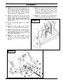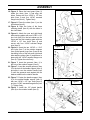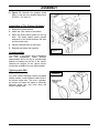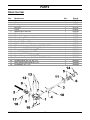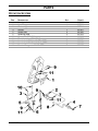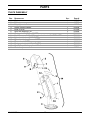
1
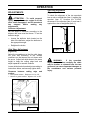
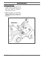
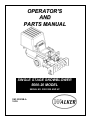
OPERATOR'S
AND
PARTS MANUAL
SINGLE STAGE SNOWBLOWER
5600-20 MODEL
SERIAL NO. 20051300 AND UP
OM 0352SB-A
10/05
Foreword
Thank you...for purchasing a Walker snowblower. Every effort has been made to provide you with the
most reliable product on the market, and we are sure you will be among our many satisfied
customers. It for any reason this product does not perform to you expectations, please contact us at
(970) 221-5614. Every customer is important to us. Your satisfaction is our goal.
Please... read this manual thoroughly! This manual is to be used in conjunction with this mower
owner’s manual and the engine manufacturer’s manual for the specific engine on the mower model
you are using. Before you operate your new snowblower, please read this entire manual.
Some of the information is crucial for proper operation and maintenance of this product – it will help
protect your investment and ensure that the snowblower performs to your satisfaction. Some of the
information is important to your safety and must be read and understood to help prevent possible
injury to your operator or others. If anything in this manual is confusing or hard to understand, please
call your service department, at (970) 221-5614, for clarification before operating or servicing this
product.
This manual covers the Model 5600-20 Single Stage Snowblower
All shields and guards must be in place for the proper and safe operation of this snowblower.
Where they are shown removed in this manual, it is for illustration purposes only. Do not operate this
product unless all shields and guards are in place.
Walker Mfg. Co. is continually striving to improve the design and performance of its products. We
reserve the right to make changes in specifications and design without thereby incurring any
obligation relative to previously manufactured products.
Sincerely
WALKER MANUFACTURING COMPANY
Bob Walker, President
INTRODUCTION
INTRODUCTION – To the Purchaser ...................................................................................................3
SAFETY PRECAUTIONS .....................................................................................................................4
Before Operation..........................................................................................................................4
Notice...........................................................................................................................................5
The Snowblower ..........................................................................................................................5
Before Operation ...........................................................................................................5
Snowblower Operation...................................................................................................6
The Tractor ..................................................................................................................................7
General Information .......................................................................................................7
Operating the Tractor.....................................................................................................7
During Operation ...........................................................................................................7
Maintenance ................................................................................................................................8
Storage ........................................................................................................................................9
DECALS ............................................................................................................................................10
ASSEMBLY .......................................................................................................................................11
Snowblower assembly ...............................................................................................................11
Snowblower Installation on the Tractor ......................................................................................14
Installation of Tire Chains (optional)...........................................................................................16
Counterweights..........................................................................................................................16
Tractors with GHS .....................................................................................................................16
OPERATION.......................................................................................................................................17
Tractor Controls .........................................................................................................................17
Lift Handle .................................................................................................................................17
Foot Trigger ...............................................................................................................................17
Rotation Handle .........................................................................................................................17
Deflector Positions.....................................................................................................................17
Engaging the Snowblower .........................................................................................................17
Stopping the Snowblower ..........................................................................................................17
Recommendation for Snowblowing............................................................................................17
OM 0352SB-A
1
TABLE OF CONTENT
ADJUSTMENTS .................................................................................................................................18
Deflector Adjustment..................................................................................................................18
Skid Show Adjustment ...............................................................................................................18
SNOW REMOVAL METHODS ...........................................................................................................19
MAINTENANCE..................................................................................................................................20
Shearbolt Replacement..............................................................................................................20
Lubrication .................................................................................................................................21
PARTS................................................................................................................................................22
Introduction ................................................................................................................................22
Snowblower Assembly ...............................................................................................................23
Drive System..............................................................................................................................25
Rotation System.........................................................................................................................26
Chute Assembly .........................................................................................................................27
TORQUE SPECIFICATION TABLE ....................................................................................................28
OM 0352SB-A
1
TABLE OF CONTENT
TO THE PURCHASER
All products are designed to give safe,
dependable service if they are operated and
maintained according to instructions. Read
and understand this manual before
operation.
Illustrations
This manual has been prepared to assist the
owner and operators in the safe operation and
suitable maintenance of the snowblower. The
information is applicable to products at the
time of manufacture and does not include
modifications made afterwards.
Direction Reference
The illustrations may not necessarily
reproduce the full detail and the exact shape of
the parts or depict the actual models, but are
intended for reference only.
All references to right and left, forward or
rearward, are from the operator's seat, facing
the steering wheel.
Read and understand this operator's manual
before attempting to put snowblower into
service. Familiarize yourself with the operating
instructions
and
all
the
safety
recommendations contained in this manual
and those labeled on the snowblower and on
the
tractor.
Follow
the
safety
recommendations and make sure that those
with whom you work follow them.
To assist your dealer in handling your needs, please record hereafter the model number and serial
number of your snowblower and tractor. It is also advisable to supply them to your insurance
company. It will be helpful in the event that snowblower or tractor is lost or stolen.
SNOWBLOWER
TRACTOR
MODEL:
SERIAL NUMBER:
DATE OF PURCHASE:
DEALER NAME:
OM 0352SB-A
2
SAFETY PRECAUTIONS
SAFETY FIRST
This symbol, the industry's "Safety Alert Symbol", is used throughout this manual and on
labels on the machine itself to warn of the possibility of personal injury. Read these
instructions carefully. It is essential that you read the instructions and safety regulations
before you attempt to assemble or use this snowblower.
DANGER :
Indicates an immediate hazardous situation which, if not avoided, will
result in death or serious injury.
WARNING : Indicates a potentially hazardous situation which, if not avoided, could
result in death or serious injury.
CAUTION :
Indicates a potentially hazardous situation which, if not avoided, may
result in minor or moderate injury.
IMPORTANT :
Indicates that snowblower or property damage could result if instructions
are not followed.
NOTE :
Gives helpful information.
All products are designed to give safe, dependable service if they are operated and maintained
according to instructions. Read and understand this manual before operation. It is the owner's
responsibility to be certain anyone operating this product reads this manual, and all other applicable
manuals, to become familiar with this snowblower and all safety precautions. Failure to do so could
result in serious personal injury or snowblower damage. If you have any questions, consult your
dealer.
BEFORE OPERATION
Children
Tragic accidents can occur if the operator is not
alert to the presence of children. Children are
generally attracted to machines and the work
being done. Never assume children will remain
where you last saw them.
1. Keep children out of the operating area and
under the watchful eye of another responsible
adult.
2. Be alert and turn machine off if children enter
the work area.
3. Before and when backing, look behind for
small children.
OM 0352SB-A
4. Never carry children while operating the
machine. They may fall off and be seriously
injured or interfere with the safe operation of
the machine.
5. Never allow children to play on the machine
or snowblower even when they are turned off.
6. Never allow children to operate the machine
even under adult supervision.
7. Use extra care when approaching blind
corners, shrubs, trees, or other obstructions
that might hide children from sight.
3
SAFETY PRECAUTIONS - continued
NOTICE
A safe operator is the best assurance against accidents. All operators, no matter how experienced
they may be, should read this operator's manual and all other related manuals before attempting to
operate the snowblower. Please read the following section and pay particular attention to all safety
recommendations contained in this manual and those labeled on the snowblower and on the tractor.
SNOWBLOWER
Before Operation
1. Read and understand both the tractor and
this operator's manual before operating the
equipment. Know how to operate all
controls and how to stop the unit and
disengage the controls quickly. Lack of
knowledge could lead to accidents.
7. Never attempt to make any adjustments
while engine is running. Read this manual
carefully to acquaint yourself with the
snowblower as well as the tractor
operator's manual. Working with unfamiliar
snowblower can lead to accidents. Be
thoroughly familiar with the controls and
proper use of the snowblower.
2. Never wear loose, torn, or bulky clothing
around the tractor and the snowblower. It
may catch on moving parts or controls,
causing injury.
8. Keep all safety guards in place and verify
hardware for proper tightening.
3. Before and during seasons, thoroughly
inspect the area where the snowblower is
to be used and remove all objects that may
be thrown or cause damage to the
snowblower.
9. Check for moving parts excessive wear
regularly. Replace worn parts with genuine
parts.
10. Replace all missing, illegible, or damaged
safety and warning decals. See list of
decals in operator's manual.
4. Set transmission to neutral and disengage
clutch, if equipped, before starting the
engine.
11. Keep safety decals clean of dirt and grime.
12. Be sure any interlock switches are
functioning correctly so the engine cannot
be started unless the Forward Speed
Control lever is in the Neutral position and
the PTO clutch is in the disengaged
position. Also, the engine should stop is
the operator lifts of the seat with the PTO
clutch in the engaged position.
5. Do not operate snowblower in wintertime
without wearing adequate winter garments.
Always wear protective clothing.
6. Handle gasoline or diesel fuel with care.
Gasoline is highly flammable and its
vapors are explosive. Use an approved
fuel container. Never add fuel to a running
engine or hot engine (allow to cool several
minutes).
Keep matches, cigarettes,
cigars, pipes, open flames or sparks away
from the fuel tank or fuel container. Always
fill fuel tank outdoors and to about one inch
from the top using a funnel or spout to
prevent spilling. Replace the machine fuel
cap and container cal securely and clean
up any spilled fuel before starting the
engine.
OM 0352SB-A
13. Do not modify or alter this snowblower or
any of its components, or any snowblower
function without first consulting your dealer.
14. Make sure the tractor is counterweighted
as recommended by your dealer. Weights
provide the necessary balance to improve
stability, traction and steering.
4
SAFETY PRECAUTIONS - continued
Snowblower Operation
10. If the snowblower starts to vibrate
abnormally, disengage the PTO, stop the
engine immediately and check for cause.
Excessive vibration is generally a sign of
trouble.
1. Before leaving the tractor/snowblower
unattended, take all possible precautions.
Park the tractor/snowblower on level
ground, place the transmission in neutral,
set the parking brake, disengage the PTO,
lower the snowblower to the ground, place
all levers including auxiliary control levers
in neutral, shut off the engine and remove
the ignition key.
11. Do not run the engine indoors except when
starting
engine
and
transporting
attachment in or out of building. Carbon
monoxide gas is colorless, odorless and
deadly.
2. Before starting the tractor/ snowblower,
remove the ice that might have
accumulated on the auger, inspect and
clean every rotating part.
12. Do not touch the engine or muffler while
the engine is running or immediately after
stopping the engine. These areas may be
hot enough to cause serious burns.
3. Prior to operation, clear work area of all
objects that can be picked up and thrown.
Mark all curbs, pipes, etc. that cannot be
moved.
13. Do not attempt to operate on steep slopes.
If operating on slopes is necessary,
exercise extreme caution when changing
direction.
4. Be sure the PTO switch/lever is in
OFF/disengaged position before starting
engine.
14. Never operate snowblower without guards,
and other safety protective devices in
place. All tractor and snowblower shields
and covers must be correctly installed at all
times. When necessary to remove these,
they must be reinstalled immediately.
5. Exercise extreme caution when operating
on or crossing a gravel drive, walks, or
roads. Stay alert for hidden hazards or
traffic.
15. Never operate snowblower near glass
enclosures, automobiles, window wells,
embankments,
etc.,
without
proper
adjustment of snow discharge angle.
6. Do not carry passengers.
7. Keep clear of all rotating parts. Do not put
hands or feet under, or into snowblower
with engine running. Be especially
observant of the snowblower areas of
discharge, intake or all other mechanical
motions.
16. Never operate machine at high transport
speeds on a slippery surface.
17. Use extra caution when backing up.
18. Disengage power to auger
transporting or when not in use.
8. Park the tractor/snowblower on level
ground, place the transmission in neutral,
set the parking brake, disengage the PTO,
lower the snowblower to the ground, place
all control levers in neutral, shut off the
engine, remove the ignition key and allow
the rotating parts to stop BEFORE
unclogging the housing or the chute and
making any repairs, adjustments or
inspections. Use only a 36" long stick of
wood to unclog the snowblower.
19. Never operate the snowblower without
good visibility and lighting.
20. Prolonged exposure to loud noise can
cause impairment or loss of hearing. Wear
a suitable hearing protective device such
as earmuffs or earplugs to protect against
objectionable or uncomfortable noises.
21. Never allow anyone near the work area.
22. Never allow anyone to operate the
snowblower until they have read the
manual completely and are thoroughly
familiar with basic tractor and snowblower
operation.
9. For your safety, do not work under any
hydraulically supported machine elements
that may creep down, suddenly drop or be
accidentally lowered.
OM 0352SB-A
when
5
SAFETY PRECAUTIONS - continued
23. Make sure the tractor is counterweighted
as recommended by your dealer. Weights
provide the necessary balance to improve
stability, traction and steering.
24. Always make sure all snowblower
components are properly installed and
securely fastened BEFORE operation.
25. Adjust housing height to clear gravel or
crushed rocks surface.
26. Do not operate the snowblower with the
chute assembly removed.
27. Keep away from chute discharge. This
chute has the capacity to throw debris at
far distances.
28. Never direct chute discharge towards
people or animals. Thrown debris can
cause serious injury.
OM 0352SB-A
6
SAFETY PRECAUTIONS - continued
MAINTENANCE
ALWAYS USE GENUINE PARTS WHEN
REPLACEMENT PARTS ARE REQUIRED
10.Do not modify or alter this snowblower or
any of its components or operating
functions. If you have questions concerning
modifications, consult with your dealer.
1. Keep the tractor and snowblower properly
maintained.
11.Do not operate a snowblower that is
defective or has missing parts. Make sure
that
all
recommended
maintenance
procedures are completed before operating
the snowblower.
2. Park the tractor/snowblower on level
ground, place the transmission in neutral,
set the parking brake, disengage the PTO,
lower the snowblower to the ground, place
all control levers in neutral, shut off the
engine and remove the ignition key and
allow the rotating parts to stop BEFORE
making any snowblower adjustments.
12.Check all controls regularly and adjust
where necessary. Make sure that the
brakes are evenly adjusted.
13.Periodically check all nuts and bolts for
tightness, especially wheel hub and rim
nuts.
3. To avoid injury, do not adjust, unblock the
driving system, or service the snowblower
with the tractor engine running. Make sure
rotating components have completely
stopped before leaving the operator’s seat.
4. Keep the tractor/snowblower clean. Snow ,
dirt or ice build-up can lead to malfunction
or personal injury from thawing and
refreezing in garage.
5. Always wear eye protection when cleaning
or servicing the snowblower.
14.To avoid serious personal injury: Escaping
hydraulic/diesel fluid under pressure can
penetrate the skin causing serious injury.
Do not use your hands to check for leaks.
Use a piece of cardboard or paper to
search for leaks. If you are injured by
escaping high pressure fluid, see a medical
doctor at once.
15.Stop engine and relieve pressure before
connecting or disconnecting hydraulic
hoses. Tighten all connections before
starting engine or pressurizing hoses.
6. DO NOT service the tractor while the
engine is running or hot, or if the unit is in
motion. Always lower snowblower to the
ground. If necessary to service snowblower
in raised position, securely support with
stands or suitable blocking before working
underneath. Do not rely on hydraulically
supported devices for your safety. They can
settle suddenly, leak down, or be
accidentally lowered.
7. Do not attempt to service machine, clear
obstructions or unclog the snowblower with
the engine running. Always shut off engine
and allow all motion to cease.
8. The
manufacturer
will
not
claim
responsibility for fitment of unapproved
parts and/or accessories and any damages
as a result of their use.
9. Make sure all shields and guards are
securely in place following all service,
cleaning, or repair work.
OM 0352SB-A
7
SAFETY PRECAUTIONS
STORAGE
Before storing the snowblower, certain
precautions should be taken to protect it
from deterioration.
1. Clean the snowblower thoroughly.
2. Make all the necessary repairs.
3. Replace all safety signs that are damaged,
lost, or otherwise become illegible. If a part
to be replaced has a sign on it, obtain a
new safety sign from your dealer and
install it in the same place as on the
removed part.
4. Repaint all parts from which paint has
worn or peeled.
5. Perform maintenance of the snowblower
as instructed under "Maintenance"
section.
6. When the snowblower are dry, oil all
moving parts. Apply oil liberally to all
surfaces to protect against rust.
7. Store in a dry place.
8. If snowblower has hydraulic components,
install protective plugs and caps on the
quick couplers.
OM 0352SB-A
8
DECALS
657761
660988
657762
661051
660263
660263
OM 0352SB-A
9
ASSEMBLY
SNOWBLOWER ASSEMBLY
The snowblower is assembled at the factory, however, snowblower kits must be assembled. Use the
present manual and lay out all parts for assembly. Separate bolts and nuts into various sizes. After
assembly, torque all the bolts according to the "Torque Specification Table" enclosed at the end of the
manual.
Snowblower Assembly
(Figure 1)
1. Figure 1: Remove the two 5/16"NC x 1/2"
flange bolts (item 1) and the gearbox shield
(item 2). Retain the bolts (item 1) for future
installation of the gearbox shield (item 2).
Figure 1
2. Figure 2: Install 1 1/4" x 1/4" flat plastic
handle (item 1) on the lifting arm (item 5).
3. Figure 2: Place some cardboard on the
ground to protect the paint then tip the
snowblower towards the front so the auger
faces down.
4. Figure 2: Insert a ø1" X 1/16" circle cotter
(item 4) in each clevis (item 2) and install
on each lifting triangle (item 6) as shown
on the figure.
5. Figure 2: Attach the tension springs
(item 3) to the snowblower housing. Pull
the lifting arm (item 5) towards the back
and attach the other end of the springs
(item 3) to the 1/4" clevis pins (item 2).
Figure 2
6. Figure 2: Push the lifting arm (item 5)
towards the front.
7. Figure 2: Lock the clevis pins (item 2) by
inserting one end of each circle cotter
(item 4) in the hole of each clevis pin.
OM 0352SB-A
10
ASSEMBLY
8. Figure 3: Install the pedal stopper (item 1),
the bent portion facing the snowblower and
secure in place with two 1/4"NC x 5/8" hex.
bolts (item 2) and two 1/4"NC serrated
flange nuts (item 3). Tighten firmly.
14. Figure 4: Secure the driveline yoke (item
2) to the gearbox shaft (item 7) with a
3/8"NC x 1 3/4" (item 3) hex. bolt, a 3/8"
lockwasher (item 5) and a 3/8"NC nylon
insert nut (item 4). Tighten firmly.
9. Figure 3: Attach the closed end of the
tension spring (item 4) to the lifting triangle
(item 5). Then, attach the open en of the
tension spring (item 4) to the hole in the
pedal (item 6).
15. Figure 4: Install the two grease fittings
(item 8) on both mounting tubes (item 9).
Figure 3
10. Put the snowblower back in its original
position.
11. Figure 4: Install a 8mm x 7mm x 25mm
key (item 1) on the gearbox shaft (item 7).
12. Figure 4: Slide the male driveline (item 2)
on the gearbox shaft (item 7). The gearbox
shaft (item 7) must be covered by the front
part of the male driveline.
13. Figure 4: Put thread sealant on the
5/16"NC X 3/8" Allen socket setscrew
(item 6) and secure the driveline yoke
(item 2).
Figure 4
OM 0352SB-A
11
ASSEMBLY
16. Figure 5: Place the hand guard (item 2)
inside the chute (item 1) and align the
holes. Fasten with four 1/4"NC x 1/2" hex
bolts (item 3) and four 1/4"NC serrated
flange nuts (item 4). Tighten firmly.
Figure 5
17. Figure 6: Place the chute (item 1) on the
chute base (item 8).
18. Figure 6: Align the holes of the three
retaining plates (item 8) with the holes in
the chute base.
19. Figure 6: Attach the rear and right hand
side retaining plates with one 1/4"NC x 1/2"
hex. bolt (item 4) in the hole shown on the
figure and the front retaining plate with two
1/4"NC x 1/2" hex. bolts (item 4) and
secure with four 1/4"NC serrated flange
nuts (item 9).
Figure 6
20. Figure 6: Insert the two 1/4"NC x 1 3/4"
hex. bolts (item 7) in the rotation stoppers
(item 6),the spacer rings (item 5) and in the
remaining holes of the rear and right hand
side retaining plates (item 3) and secure in
place with two 1/4"NC serrated flange nuts
(item 9). Tighten the nuts firmly.
21. Figure 7: Insert the grommet (item 1) in
the hole of the rotation support (item 2).
22. Figure 7: Insert the second grommet (item
3) in the hole of the handle support (item 4)
and slide it over the rotation handle (item
5) until the grommet rests against the flat
washer welded on the rotation handle.
23. Figure 7: Fasten the handle support (item
4) to the welded handle support (item 2)
with two 1/4"NC x 1/2" hex. bolts (item 6)
and two 1/4"NC serrated flange bolts (item
7). Tighten firmly.
Figure 7
24. Figure 7: Install the 1/2" plastic handle
(item 8) on the rotation handle (item 5).
OM 0352SB-A
12
ASSEMBLY
Snowblower Installation on the Tractor
1. Remove the mower deck from the tractor if
necessary. Refer to the appropriate Tractor
Owner’s Manuel.
Figure 8
2. Figure 8: Attach each lift chain (item 5) to
the lift bracket (item 1) with a 5/16" NC x
1 1/4" bolt (item 6) and a 5/16" NC nylon
insert locknut (item 7).
3. Figure 8: Attach each lift bracket (item 1)
to the predrilled holes (item 2) on the front
chassis cross bar with a 5/16"NC x 1" bolt
(item 3) and a 5/16"NC serrated flange nut
(item 4).
NOTE: Predrilled holes exist only on Walker
tractors built after 1984. For earlier models, drill
two 5/16" (8mm) holes in the front chassis
cross bar at the positions indicated.
IMPORTANT: For all 1980 to 1984 tractors,
remove the battery before drilling the right hand
hole. Reinstall the battery after the lift brackets
have been installed. Refer to the appropriate
Tractor Owner’s Manual for battery removal
and installation procedures.
4. Figure 9: Place the male half driveline
(item 1) of the snowblower PTO shaft into
the socket of the female PTO with quick
coupler (item 2) and rotate the PTO shaft
until it is aligned correctly with the socket in
the female PTO with quick coupler, then
slide together.
Figure 9
OM 0352SB-A
13
ASSEMBLAGE
5. Figure 10: Lightly grease the tractor
support arms (item 1).
6. Figure 10: Align the mounting tubes (item
2) with the tractor support arms (item 1)
and slide the snowblower assembly onto
tractor support arms (item 1).
Figure 10
7. Figure 10: Reaching under the tractor,
pull the ring back on the PTO quick
coupler (item 3), slide the coupler onto the
tractor splined shaft, and release the
coupler ring.
NOTE: Model MS and earlier Model MC do
not have the PTO quick coupler. Use sliding
joint to connect tractor to snowblower PTO.
IMPORTANT: To prevent damage to the
machine, make sure the PTO quick coupler is
securely locked on the tractor, with the
locking balls fully seated in the groove and
the ring full forward position. After installation,
pull on the shaft to check for security.
8. Figure 10: Insert the hairpins (item 4) in
the ends of the tractor support arms
(item 1).
Figure 11
9. Figure 11 Pull the lift handle back
(item 1), press the foot trigger (item 2)
then push the snowblower lift handle
forward against the spring pressure in the
forward position.
10. Figure 11: Remove the 5/16" pin from
each clevis (item 3) and insert the third
link of each chain (item 4) on each clevis
(item 3) as well as a ø1" X 1/16" circle
cotter (item 5).
11. Figure 11: Attach a clevis to each lifting
triangle (item 6) with the 5/16" pin.
12. Figure 11: Lock the clevis pins (item 3) by
inserting one end of each circle cotter
(item 5) in the hole of each clevis pin.
NOTE : Use a bungee cord or strap to secure
lift handle in forward position while connecting
lift chains to tractor.
CAUTION: DO NOT release the lift
handle before releasing the foot trigger or
before the snowblower has reached the
DOWN position.
OM 0352SB-A
14
ASSEMBLY
13. Figure 12: Reinstall the gearbox shield
(item 1) and the two serrated flange bolt
5/16"NC x 1/2" (item 2).
Installation of Tire Chains (Optional)
1. Remove the tractor wheels.
2. Attach the 2 tire chains to the wheels.
3. Place the wheel spacer plates on the lug
bolts. The wheel spacer plates provide
clearance for the chains between the tires
and the tractor body.
4. Place the wheels back on the tractor.
5. Reinstall and tighten the lug bolts.
Figure 12
Counterweights
For stability of the tractor when transporting
with the snowblower raised position,
approximately 80 lbs (36 kg) of counterweight
should be installed on the tail of the tractor.
Optional tail weights for the various tractor
models are available from your Walker dealer.
Tractors with GHS
(Figure 13)
Figure 13
For GHS (Grass Handling System) equipped
Walker tractors; install a blower intake cover in
the blower intake tube. The cover «unloads»
the blower and seals the intake to effectively
eliminate power loss and noise when the
blower is being used.
OM 0352SB-A
15
OPERATION
WARNING:
Before operating the
snowblower, become familiar with the
location and function of all operator
controls. Knowing the location, function,
and operation of these controls is
important for safe and efficient operation of
the snowblower.
CAUTION: ALWAYS disengage the
PTO clutch and plut the Forward Speed
Control (FSC) in the NEUTRAL-PARK
position before starting the engine.
NOTE: For cold weather operation, follow the
proper operating procedures in the appropriate
Tractor Owner’s Manual. Allow sufficient time
for the tractor engine to warm up before
engaging the snowblower.
Tractor Controls
Refer to the appropriate Tractor Owner’s
Manual for complete information about tractor
operating controls.
Engaging The Snowblower
Lift Handle
CAUTION:
Before operating the
snowblower, read and understand all
Safety
Instructions
and
Operating
Instruction.
The lift handle is located to the right of the
operator at the back of the snowblower right
footrest. The lift handle is used to raise and
lower the snowblower. Moving the handle
forward lowers the snowblower; moving it
backward raises the snowblower.
1. Set the engine throttle at about 1/3 speed.
DO NOT attempt to engage the PTO clutch
at high engine speed. This will drastically
shorten drive belt life. Use only moderate
engine speed when engaging the PTO
clutch.
Foot Trigger
The foot trigger is located on the right footrest.
The foot trigger and lift handle are used
together to lower the snowblower. Pull the lift
handle back, press the foot trigger, and hold
on to the lift handle while letting it move
forward to lower the snowblower.
2. Pull the PTO clutch lever SLOWLY engage
the snowblower.
NOTE: For cold weather operation, allow
sufficient time for the snowblower component
(i.e., gearbox grease) to warm up before
beginning to blow snow.
IMPORTANT: To avoid the snowblower
dropping down with force, DO NOT release
the lift handle while depressing the foot
trigger or before the snowblower has
reached the ground.
CAUTION: A safety interlock switch
(seat switch) will cause the engine to stop
if the PTO clutch is engaged and the tractor
operator is not on the seat. The function of
this switch should be checked by the
operator raising off the seat and engaging
the PTO clutch; the engine should stop. If
the switch is not working, it should be
repaired or replaced before operating the
snowblower. DO NOT disconnect the safety
switches; they are for the operator’s
protection.
Rotation Handle
The crank is located to the left of the operator
at the back of the snowblower. Turn the crank
clockwise and the chute will turn counter
clockwise.
Deflector Positions
The knob is located to the right of the operator
at the right side of the chute of the
snowblower. Loosen the knob and adjust the
deflector at the desired position, then tighten
the knob securely.
IMPORTANT: DO NOT engage the PTO
clutch when transporting the machine. DO
NOT engage the PTO clutch with the PTO
shaft disconnected (the snowblower
removed from the tractor).
Sliding the deflector higher throws snow higher
and farther. Sliding the deflector down throws
snow lower, and closer.
OM 0352SB-A
16
OPERATION
The
hydrostatic
IMPORTANT:
transmissions lock prevents the machine
from rolling freely with the engine stopped.
However, if the machine is parked on a
slope, it is necessary to ENGAGE the
parking BRAKE to prevent the machine
creeping. This is due to a small amount of
slippage in the hydrostatic transmission,
especially when the transmission fluid is
warm.
CAUTION: If the auger strikes a solid
object or the machine begins to vibrate
abnormally, immediately disengage the
PTO clutch, stop the engine and wait for all
moving parts to stop. Disconnect the fuel
solenoid wire (diesel engines) or the park
plug wire(s) (gasoline engines) to prevent
accidental starting. Thoroughly inspect the
snowblower and repair any damage before
restarting the engine and operating the
machine. Make sure auger blades are in
good condition and all bolts are tight.
Recommendation For Snowblowing
IMPORTANT: Operate the engine at full
speed when snowblowing, to allow the
engine to produce full horse power and
increase efficiency of the engine cooling
system.
Stopping The Snowblower
1. Slow the engine to idle; put the throttle in
the IDLE position.
2. Pull the steering lever to the NEUTRAL
position and move the Forward Speed
Control (FSC) lever backward to the
NEUTRAL-PARK position.
1. When blowing through deep snowdrifts, let
the snowblower work its way through the
drifts. For best results, raise the
snowblower skid shoes and remove a top
layer of snow, then lower the skid shoes
and pass through the area a second time
to remove the remaining snow.
3. Disengage the PTO clutch.
IMPORTANT: DO NOT disengage the PTO
clutch with high engine speed (above 1/2"
throttle) since the brake action of the PTO
drive will cause premature wear of the
brake band.
2. When snowblowing, operate the engine at
or near FULL THROTTLE for the best
snowblowing action. The engine is
designed to operate at full speed.
3. Use optional tire chains or optional allterrain tires to improve traction.
WARNING: A brake stops the auger
from freewheeling within five seconds after
disengaging the PTO clutch. If the brake
system malfunctions and the auger does
not stop within five seconds, the brake
should be adjusted or repaired before
operating the snowblower. Refer to the
appropriate Tractor Owner’s Manual for
adjustment procedures.
4. Disengage the PTO clutch to stop the
snowblower when driving the machine but
not blowing snow.
5. Avoid damage to property and extra
snowblowing work by carefully choosing
the direction to move the snow. Orient the
chute away from people and property due
to possibility of thrown objects.
4. Turn the ignition switch OFF
5. Engage the parking brake.
6. To momentarily increase traction in case
the drive wheels are slipping, use the lift
handle to raise the snowblower slightly and
transfer extra weight on the drive wheels.
WARNING: Remove the key from the
ignition switch when leaving the machine
unattended. This will prevent children and
inexperienced operators from starting the
engine.
OM 0352SB-A
17
OPERATION
Sprocket Alignment
ADJUSTMENTS
(Figure 15)
To check the alignment of the two sprockets
lean a ruler or straight bar (item 1) against the
sprocket (item 3). Unscrew the 5/16"NC
setscrews of the sprocket (item 2) and lean it
against the ruler or straight bar (item 1).
ATTENTION : To avoid personal
injury, be sure the tractor engine is off, the
drive shaft disengaged, and all movement
has
stopped
before
making
any
adjustments.
2
Deflector Adjustment
Set the angle of deflection according to the
distance the snow must be thrown. To set the
deflector angle:
•
•
Loosen the deflector knob located on the
side of the deflector; adjust the deflector to
the appropriate angle.
1
Retighten the knobs.
Skid Shoe Adjustment
Figure 15
(Figure 14)
Adjust the snowblower so that the skid shoes
run level and according to the surface
conditions so that stones are not thrown with
the snow. Adjust both skid shoes to the same
height to keep the cutting edge level and
adjust upwards for smooth surfaces.
WARNING:
If the sprockets
alignment is not done carefully the chain
may be broken or released from the two
gears and can cause important damages to
the snowblower and serious personal
injury.
Loosen skid shoe bolts and adjust according to
instructions below, and securely tighten bolts:
Clearance
surface:
between
cutting
edge
and
• Level paved surface : Adjust to 1/16" to 1/8"
• Uneven or gravel surface: Adjust to 1/2" to 5/8"
Figure 14
OM 0352SB-A
3
18
OPERATION
SNOW REMOVAL METHODS
When removing snow, do not use the snowblower as a dozer blade to push snow. Let the snowblower
work its way through deep drifts. If the speed of your tractor is too fast, the snowblower may become
overloaded and clog. For best results, raise the snowblower and remove a top layer of snow. A
second pass with the snowblower will remove the remaining snow.
IMPORTANT: Use full engine RPM power when removing wet, sticky snow. Low engine RPM power
will tend to clog the chute.
WARNING
To avoid serious personal injury: Do not use hands or feet to unclog chute. Do not attempt
to clear clogged chute of snow while tractor engine is running. If the chute clogs, disengage
the PTO shaft, shut off the engine, set the parking brake, lower snowblower to the ground,
place transmission in neutral, remove the ignition key, wait for all movement to stop, and then
clear the snow from the chute.
A definite pattern of operation is required to thoroughly clean the snow area. These patterns
will avoid throwing snow in unwanted places as well as eliminating a second removal of snow
Where it is possible to throw the snow to the
left and right (above), as on a long driveway, it
is advantageous to start in the middle. Plow
from one end to the other, throwing snow to
both sides without changing the direction of
the discharge guide.
OM 0352SB-A
If the snow can only be thrown to one side of
the driveway or sidewalk (above), start on the
opposite side. At the end of the first pass,
rotate the discharge guide 180 degrees for the
return pass. At the end of each succeeding
pass, rotate the discharge guide 180 degrees
to maintain direction of throw in the same area.
19
MAINTENANCE
Shearbolt Replacement
1. To replace the shearbolt, take off the
gearbox shield by removing the two
5/16"NC x 1/2" flange bolts. The hole in the
plate helps remove the shearbolt if
fragments remain in the hole.
2. Replace the 5/16"NC x 2 1/4" shearbolt a
genuine replacement bolt and a 5/16"
lockwasher and a 5/16" nut. Replace the
gearbox shield with the two 5/16"NC x 1/2"
flange bolts.
OM 0352SB-A
20
MAINTENANCE
Lubrication
DESCRIPTION
INTERVAL
LUBRICATION REQUIRED
8 hours
Driveline
Driving chain
Gearbox
Grease each universal joint
Separate the sliding parts and cover each
part with grease
24 hours
2 hours and after
each operation
Lubricate with chain saw lubricant
Check grease level. If needed, add Unirex
Ep2 Grease
every month
Lift Handle Mounting
Tubes
8 hours
Grease fitting
Rotation Worm
4 hours
Lubricate with chain saw lubricant
OM 0352SB-A
21
PARTS
INTRODUCTION
All parts are illustrated in "exploded views" which show the individual parts in their normal relationship
to each other. Reference numbers are used in the illustrations. These numbers correspond to those in
the "Reference Number" (REF) column, and are followed by the description and quantity required.
O/L - "Obtain Locally" in the part number column indicates common hardware that is available at your
local hardware supply.
All reference to right and left, forward or rearward, are from the operator seat, looking at the machine
while operating.
Orders must give the complete description, correct part number, the total amount required, the serial
number, the method of shipment and the shipping address.
The manufacturer reserves the rights to change, modify, or eliminate from time to time, for technical
or other reasons, certain or all data, specifications, or the product or products themselves, without any
liability or obligation.
OM 0352SB-A
22
PARTS
SNOWBLOWER ASSEMBLY
OM 0352SB-A
23
PARTS
SNOWBLOWER ASSEMBLY
REF.
1
2
3
4
5
6
7
8
9
10
11
12
13
14
15
16
17
18
19
20
21
22
23
24
25
26
27
28
29
30
31
32
33
34
35
DESCRIPTION
Snowblower housing and foot rest
1 stage auger
Cutting edge
Skid shoes
Chain guard
Driveline shield
Gearbox shield
Pedal stopper
Bearing flange 3 holes with nut
Chain 3/16"
Spacer ring
Chain tensioner automatic
Torsion spring
Tension spring 1/2" x 3 9/16"
Tension spring 1 1/2" x 9"
Chain #40 74 links (with connecting link)
Connecting link #40
1" Bearing with allen socket set screw
Grease fitting 1/4" NF
Clevis 1/4" body, 5/16" pin
Circle cutter ø1" X 1/16"
Pin ø1/2" x 2 1/4" PTD
Cotter pin Ø1/8" X 1 1/2"
Hex. bolt ø1/4"NC X 1/2" GR.5 ,PTD
Hex. bolt ø1/4" NC X 5/8" Gr.5 PTD
Hex. bolt Ø1/4" X 2 3/4" NC GR.5 PTD
Carriage bolt 5/16" NC X 3/4" PTD
Serrated flange bolt 5/16"NC X 1/2" PTD
Hex. bolt 5/16" NC X 1" LG. GR.5, PTD
Hex. bolt 5/16" NC X 1 1/4" LG. GR.5, PTD
Serrated flange nut 1/4" NC. PTD
Serrated flange nut 5/16" NC, PTD
Nylon insert locknut 5/16" NC, GR.5, PTD
Flat rectangular grip 1 1/4" X 1/4"
Lift bracket #5628-2
OM 0352SB-A
24
QTY.
1
1
1
2
1
1
1
1
2
2
1
1
1
1
2
1
1
2
5
4
4
1
1
2
2
1
10
8
2
2
5
12
2
1
2
PART #
667619
667620
667643
667626
667629
667630
667631
667632
665743
667652
667666
665960
2200012
659578
657363
3300018
659721
665494
654106
A-10368
1900009
4600036
1500018
0100001
0100002
0100013
0300002
0200065
0100019
0100020
0900058
0900036
1000005
663997
4200018
PARTS
DRIVE SYSTEM
REF.
1
2
3
4
5
6
7
8
9
10
11
12
13
14
15
16
17
18
DESCRIPTION
Gear box
Oil seal
Bearing
Plug 3/8"
O-ring
Male driveline Série 06
Drive shaft
Shear bushing
Bearing flange 2 holes - ø1"
1" bearing with allen socket set screws
Key 8mm X 7mm X 35mm
Key 8mm X 7mm X 25mm
Allen socket set screw Gr.5 black, 5/16"NC X 3/8"
Shear bolt ø5/16" NC X 2 1/2" (.215) (with lockwasher and nut)
Carriage bolt 5/16" NC X 5/8" PTD
Hex. bolt 3/8" NC X 1 3/4" PTD
Hex. bolt ø3/8"NC X 4"
Serrated flange nut 5/16" NC, PTD
Allen socket set screw Gr.5 black, 5/16"NC X 1/4"
Serrated flange nut 3/8" NC PTD
Nylon insert locknut ø3/8 NC PTD
Lockwasher 3/8", PTD
OM 0352SB-A
25
QTY.
1
2
4
1
1
1
1
1
2
1
1
1
1
1
2
1
3
2
1
3
1
1
PART #
4500056
662630
661728
661739
664656
4700102
667624
667625
654787
665494
660062
660063
0500010
667342
0300001
0100041
0100049
0900036
0500008
0900035
1000006
1200004
PARTS
ROTATION SYSTEM
REF.
1
2
3
4
5
6
7
8
9
10
11
DESCRIPTION
Hand guard
Handle support
Chute stopper
Handle
Spacer ring
Retaining plate
Grommet ø.680 of hole
Plastic handle ø1/2" X 3" LG.
Hex. bolt ø1/4"NC X 1/2" GR.5 ,PTD
Hex. bolt ø1/4" NC X 1 3/4" Gr.5 PTD
Serrated flange nut 1/4" NC. PTD
OM 0352SB-A
QTY.
1
1
1
1
2
3
2
1
10
2
12
26
PART #
667622
667628
667644
667627
667645
657333
665959
656797
0100001
0100009
0900058
PARTS
CHUTE ASSEMBLY
REF.
1
2
3
4
5
6
7
8
9
10
11
12
13
14
DESCRIPTION
Chute
Deflector
Polyethylene deflector
Plastic rotation bushing
Knob 5/16"NC
Nylon flat washer ø7/16"
Carriage bolt 5/16"NC x 5/8" PTD
Machine screw 10-32 x 5/8" round socket head - QUADREX PTD
Nylon insert locknut 5/16"NC PTD
Nylon insert locknut 5mm x .80 PTD
Flat washer 1/4" PTD
Steel pop rivet (nail 1/16", 1/8" GRIP)
Steel flat washer for pop rivet 1/8"
Chute Ass'y
OM 0352SB-A
27
QTY.
1
1
1
1
1
3
3
3
2
3
3
2
2
1
PART #
667646
665738
667623
665948
657309
658468
0300001
2700008
1000005
1000020
1400016
1700009
1700008
667621
TORQUE SPECIFICATION TABLE
GENERAL SPECIFICATION TABLE
Use the following torques when special torques are not given Note: These values apply to fasteners
as received from supplier, when dry. These values do not apply if lubricants are used.
BOLT SIZES (SAE)
TORQUE
INCHES
Pounds-Foot
Newtons-Meter
¼
5/16
3/8
7/16
½
9/16
5/8
¾
7/8
1
1 1/8
1¼
1 3/8
1½
5
10
20
25
88
121
165
297
440
638
840
1180
1570
2070
7
14
27
41
119
164
224
403
597
865
1139
1600
2129
2807
BOLT SIZES (METRIC)
TORQUE
MILLIMETERS
Pounds-Foot
Newtons-Meter
M6
M8
M10
M12
M14
M16
M18
M20
10
22
40
59
93
130
168
205
13
30
54
80
126
176
228
278
OM 0352SB-A
28
Printed in Canda