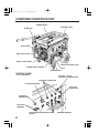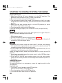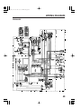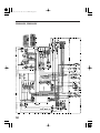
1
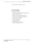
EM3800SX•EM5000SX•EM6500SX
K2:EM5000SX
31Z21600
00X31-Z21-6000
See page 54 for instructions
on assembling your generator.
03/11/17 18:38:36 31Z21600_001
The engine exhaust from this product
contains chemicals known to the State
of California to cause cancer, birth
defects or other reproductive harm.
The generator is a potential source of electrical shock if misused. Do
not expose the generator to moisture, rain or snow. Do not let the
generator get wet, and do not operate it with wet hands.
Keep this owner’s manual handy, so you can refer to it at any time.
This owner’s manual is considered a permanent part of the generator
and should remain with the generator if resold.
The information and specifications included in this publication were in
effect at the time of approval for printing. Honda Motor Co., Ltd.
reserves the right, however, to discontinue or change specifications or
design at any time without notice and without incurring any obligation
whatever. No part of this publication may be reproduced without
written permission.
03/11/17 18:38:42 31Z21600_002
Congratulations on your selection of a Honda generator. We are
certain you will be pleased with your purchase of one of the finest
generators on the market.
We want to help you get the best results from your new generator and
to operate it safely. This manual contains the information on how to
do that; please read it carefully.
As you read this manual, you will find information preceded by a
symbol. That information is intended to help you avoid
damage to your generator, other property, or the environment.
We suggest you read the warranty policy to fully understand its
coverage and your responsibilities of ownership. The warranty policy
is a separate document that should have been given to you by your
dealer.
When your generator needs scheduled maintenance, keep in mind
that your Honda servicing dealer is specially trained in servicing
Honda generators. Your authorized Honda servicing dealer is
dedicated to your satisfaction and will be pleased to answer your
questions and concerns.
Best Wishes,
Honda Motor Co., Ltd.
1
03/11/17 18:38:55 31Z21600_003
A FEW WORDS ABOUT SAFETY
Your safety and the safety of others are very important. And using
this generator safely is an important responsibility.
To help you make informed decisions about safety, we have provided
operating procedures and other information on labels and in this
manual. This information alerts you to potential hazards that could
hurt you or others.
Of course, it is not practical or possible to warn you about all the
hazards associated with operating or maintaining a generator. You
must use your own good judgement.
You will find important safety information in a variety of forms,
including:
Safety Labels − on the generator.
Safety Messages − preceded by a safety alert symbol
of three signal words, DANGER, WARNING, or CAUTION.
and one
These signal words mean:
You WILL be KILLED or SERIOUSLY HURT if
you don’t follow instructions.
You CAN be KILLED or SERIOUSLY HURT if
you don’t follow instructions.
You CAN be HURT if you don’t follow instructions.
Safety Headings − such as IMPORTANT SAFETY INFORMATION.
Safety Section − such as GENERAT OR SAF ET Y .
Instructions − how to use this generator correctly and safely.
This entire book is filled with important safety information − please
read it carefully.
2
03/11/17 18:39:00 31Z21600_004
CONTENTS
SAFETY ....................................................................................................... 5
Safety Label Locations ........................................................................ 5
Safety Information ............................................................................... 6
COMPONENT IDENTIFICATION ............................................................... 8
CONTROLS ............................................................................................... 10
Engine Switch ..................................................................................... 10
Recoil Starter ...................................................................................... 10
Fuel Valve Lever ................................................................................. 11
Choke Rod ........................................................................................... 11
Voltage Selector Switch (Dual Voltage System) ............................. 12
Ground Terminal ................................................................................ 12
DC Terminal ........................................................................................ 13
DC Circuit Protector ........................................................................... 13
Oil Alert System ............................................................................... 14
Auto Throttle System ....................................................................... 14
AC Circuit Breaker .............................................................................. 15
AC Circuit Protector ........................................................................... 16
GENERATOR USE .................................................................................... 17
Connections to a Building’s Electrical System ................................ 17
Ground System ...................................................................................17
Special Requirements ........................................................................ 17
AC Applications .................................................................................. 18
AC Operation ...................................................................................... 19
AC Receptacle Selection .................................................................... 20
DC Operation ...................................................................................... 23
Auto Throttle System ....................................................................... 25
High Altitude Operation ..................................................................... 26
PRE-OPERATION CHECK ........................................................................ 27
Engine Oil ........................................................................................... 27
Fuel ...................................................................................................... 28
STARTING THE ENGINE/STOPPING THE ENGINE ............................... 30
MAINTENANCE ....................................................................................... 31
The Importance of Maintenance ....................................................... 31
Maintenance Safety ........................................................................... 32
Emission Control System Information ............................................. 33
Air Index .............................................................................................. 36
Maintenance Schedule ...................................................................... 37
Engine Oil Change ............................................................................. 38
Air Cleaner Service ............................................................................ 39
Fuel Sediment Cup Cleaning ............................................................ 40
Spark Plug Service ............................................................................. 41
Spark Arrester Maintenance ............................................................. 42
Fuse Replacement .............................................................................. 43
3
03/11/17 18:39:02 31Z21600_005
TRANSPORTING/STORAGE ................................................................... 44
TROUBLESHOOTING .............................................................................. 47
WIRING DIAGRAM .................................................................................. 49
SPECIFICATIONS ..................................................................................... 51
ASSEMBLY ............................................................................................... 54
WARRANTY SERVICE INFORMATION .................................................. 66
INDEX ....................................................................................................... 67
4
03/11/17 18:39:14 31Z21600_006
SAFETY
SAFETY LABEL LOCATIONS
These labels warn you of potential hazards that can cause serious
injury. Read them carefully.
If a label comes off or becomes hard to read, contact your Honda
generator dealer for a replacement.
5
03/11/17 18:39:22 31Z21600_007
SAFETY INFORMATION
Honda generators are designed to give safe and dependable service if
operated according to instructions. Read and understand this owner’s
manual before operating your generator. You can help prevent
accidents by being familiar with your generator’s controls, and by
observing safe operating procedures.
Operator Responsibility
Know how to stop the generator quickly in case of emergency.
Understand the use of all generator controls, output receptacles,
and connections.
Be sure that anyone who operates the generator receives proper
instruction. Do not let children operate the generator without
parental supervision.
Carbon Monoxide Hazards
Exhaust contains poisonous carbon monoxide, a colorless and
odorless gas. Breathing exhaust can cause loss of consciousness
and may lead to death.
If you run the generator in an area that is confined, or even partially
enclosed, the air you breathe could contain a dangerous amount of
exhaust gas. To keep exhaust gas from accumulating, provide
adequate ventilation.
6
03/11/17 18:39:32 31Z21600_008
Electric Shock Hazards
The generator produces enough electric power to cause a serious
shock or electrocution if misused.
Using a generator or electrical appliance in wet conditions, such as
rain or snow, or near a pool or sprinkler system, or when your hands
are wet, could result in electrocution. Keep the generator dry.
If the generator is stored outdoors, unprotected from the weather,
check all of the electrical components on the control panel, before
each use. Moisture or ice can cause a malfunction or short circuit in
electrical components which could result in electrocution.
Do not connect to a building electrical system unless an isolation
switch has been installed by a qualified electrician.
Fire and Burn Hazards
The exhaust system gets hot enough to ignite some materials.
−Keep the generator at least 3 feet (1 meter) away from buildings
and other equipment during operation.
−Do not enclose the generator in any structure.
−Keep flammable materials away from the generator.
The muffler becomes very hot during operation and remains hot for
a while after stopping the engine. Be careful not to touch the muffler
while it is hot. Let the engine cool before storing the generator
indoors.
Gasoline is extremely flammable and is explosive under certain
conditions. Do not smoke or allow flames or sparks where the
generator is refueled or where gasoline is stored. Refuel in a wellventilated area with the engine stopped.
Fuel vapors are extremely flammable and may ignite after the
engine has started. Make sure that any spilled fuel has been wiped
up before starting the generator.
7
03/11/17 18:39:39 31Z21600_009
COMPONENT IDENTIFICATION
ENGINE SWITCH
CONTROL PANEL
CHOKE ROD
AIR CLEANER
FUEL VALVE LEVER
RECOIL STARTER GRIP
OIL FILTER CAP/DIP STICK
ENGINE SERIAL NUMBER
FUSE
OIL DRAIN BOLT
CONTROL PANEL
*
1:Except EM3800SX
120 ONLY−120/240
VOLTAGE SELECTOR SWITCH
AC CIRCUIT PROTECTORS
AC CIRCUIT BREAKER
120/240 AC
RECEPTACLE
DC CIRCUIT
PROTECTOR
*
1
DC OUTPUT
TERMINAL
AUTO THROTTLE AC RECEPTACLES
SWITCH
8
GROUND TERMINAL
03/11/17 18:39:56 31Z21600_011
CONTROLS
Engine Switch
To start and stop the engine.
Key position:
OFF:
To stop the engine. Key can be removed/inserted.
ON:
To run the engine after starting.
START: To start the engine by operating the starter motor.
OFF
ON
START
ENGINE SWITCH
Recoil Starter
To start the engine, pull the starter grip lightly until resistance is felt,
then pull briskly.
Do not allow the starter grip to snap back against the engine. Return it
gently to prevent damage to the starter.
The recoil starter is used to start the engine if the generator is not
equipped with a 12 volt battery to operate the starter motor, or if the
battery does not contain adequate charge to operate the starter motor.
RECOIL STARTER
10
STARTER GRIP
03/11/17 18:40:02 31Z21600_012
Fuel Valve Lever
The fuel valve is located between the fuel tank and carburetor. When
the valve lever is in the ON position, fuel is allowed to flow from the
fuel tank to the carburetor. Be sure to return the fuel valve lever to the
OFF position after stopping the engine.
FUEL VALVE LEVER
OFF
ON
Choke Rod
The choke is used to provide an enriched fuel mixture when starting a
cold engine. It can be opened and closed by operating the choke rod
manually. Pull the rod out toward CLOSED to enrich the mixture for
cold starting.
CHOKE ROD
OPEN
CLOSED
11
03/11/17 18:40:11 31Z21600_013
Voltage Selector Switch (Dual Voltage System)
The voltage selector switch switches the main power carrying
windings of the generator to produce ‘‘120V ONLY’’ or ‘‘120/240V’’. If a
240V appliance is connected to the 4-prong receptacle, the switch
must be in the ‘‘120/240V’’ position. If only a 120V appliance is being
connected to any of the 120V 3-prong receptacles, select the ‘‘120V
ONLY’’ position.
Switch Position
The 120V and 120/240V receptacles can be used
120/240V:
simultaneously.
120V ONLY: ONLY the 120V receptacles can be used. Do not use the
120/240V receptacle in this position. The most power
will be available at the 30A 120V locking plug
receptacle.
VOLTAGE SELECTOR SWITCH
120/240V
120/240V
120V ONLY
120V ONLY
GROUND TERMINAL
Ground Terminal
The generator ground terminal is connected to the frame of the
generator, the metal non-current-carrying parts of the generator, and
the ground terminals of each receptacle.
Before using the ground terminal, consult a qualified electrician,
electrical inspector or local agency having jurisdiction for local codes
or ordinances that apply to the intended use of the generator.
12
03/11/17 18:40:17 31Z21600_014
DC Terminals
The DC terminals may ONLY be used for charging 12 volt automotive
type batteries.
The terminals are colored red to identify the positive (+) terminal and
black to identify the negative (−) terminal. The battery must be
connected to the generator DC terminals with the proper polarity
(battery positive to generator red terminal and battery negative to the
generator black terminal).
DC Circuit Protector
The DC circuit protector automatically shuts off the DC battery
charging circuit when the DC charging circuit is overloaded, when
there is a problem with the battery, or when the connections between
the battery and the generator are improper.
DC CIRCUIT
PROTECTOR
NEGATIVE TERMINAL
(BLACK)
POSITIVE TERMINAL
(RED)
13
03/11/17 18:40:26 31Z21600_015
Oil Alert System
The Oil Alert system is designed to prevent engine damage caused
by an insufficient amount of oil in the crankcase. Before the oil level in
the crankcase can fall below a safe limit, the Oil Alert system will
automatically stop the engine (the engine switch will remain in the ON
position). The Oil Alert system should not take the place of checking
the oil level before each use.
If the engine stops and will not restart, check the engine oil level (see
page 27 ) before troubleshooting in other areas.
Auto Throttle System
The auto throttle system automatically reduces engine speed when all
loads are turned off or disconnected. When appliances are turned on
or reconnected, the engine returns to the rated speed.
Switch Position
AUTO: Recommended to minimize fuel consumption and further
reduce noise levels when no load is applied to the generator.
OFF:
The auto throttle system does not operate.
Recommended to minimize warm-up time when the
generator is started and starting load with large start-up
power equipments.
AUTO THROTTLE SWITCH
OFF
ON
OFF
ON
14
03/11/17 18:40:31 31Z21600_016
AC Circuit Breaker
The AC circuit breaker will automatically switch OFF if there is a short
circuit or a significant overload of the generator at the receptacle. If the
AC circuit breaker is switched OFF automatically, check that the
appliance is working properly and does not exceed the rated load
capacity of the circuit before switching the AC circuit breaker ON again.
The AC circuit breaker may be used to switch the generator power ON
or OFF.
ON
OFF
AC CIRCUIT BREAKER
15
03/11/17 18:40:35 31Z21600_017
AC Circuit Protector
The AC circuit protectors will automatically switch OFF if there is a
short circuit or a significant overload of the generator at the 20A 120V,
30A 120V locking plug, or 120/240V locking plug receptacle. If a AC
circuit protector switches OFF automatically, check that the appliance
is working properly and does not exceed the rated load capacity of the
circuit before resetting the AC circuit protector ON.
*
1:Except EM3800SX
AC CIRCUIT PROTECTORS
ON
*
1
OFF
16
03/11/17 18:40:44 31Z21600_018
GENERATOR USE
Connections to a Building Electrical System
Connections for standby power to a building electrical system must be
made by a qualified electrician. The connection must isolate the
generator power from utility power, and must comply with all
applicable laws and electrical codes. A transfer switch, which isolates
generator power from utility power, is available through authorized
Honda generator dealers.
Improper connections to a building electrical system can allow
electrical current from the generator to backfeed into the utility lines.
Such backfeed may electrocute utility company workers or others
who contact the lines during a power outage, and the generator may
explode, burn, or cause fires when utility power is restored. Consult
the utility company or a qualified electrician.
Ground System
Honda portable generators have a system ground that connects
generator frame components to the ground terminals in the AC output
receptacles. The system ground is not connected to the AC neutral
wire. If the generator is tested by a receptacle tester, it will show the
same ground circuit condition as for a home receptacle.
Special Requirements
There may be Federal or State Occupational Safety and Health
Administration (OSHA) regulations, local codes, or ordinances that
apply to the intended use of the generator. Please consult a qualified
electrician, electrical inspector, or the local agency having jurisdiction.
In some areas, generators are required to be registered with local
utility companies.
17
03/11/17 18:40:55 31Z21600_019
AC Applications
Before connecting an appliance or power cord to the generator:
Make sure that it is in good working order. Faulty appliances or
power cords can create a potential for electrical shock.
If an appliance begins to operate abnormally, becomes sluggish or
stops suddenly, turn it off immediately. Disconnect the appliance,
and determine whether the problem is the appliance, or if the rated
load capacity of the generator has been exceeded.
Make sure that the electrical rating of the tool or appliance does not
exceed that of the generator. Never exceed the maximum power
rating of the generator. Power levels between rated and maximum
may be used for no more than 30 minutes.
Substantial overloading will open the circuit breaker. Exceeding the
time limit for maximum power operation or slightly overloading the
generator may not switch the circuit breaker or circuit protector OFF,
but will shorten the service life of the generator.
Limit operation requiring maximum power to 30 minutes.
Maximum power is:
EM3800SX: 3,800 VA
EM5000SX: 5,000 VA
EM6500SX: 6,500 VA
For continuous operation (longer than 30 minutes), do not exceed the
rated power.
Rated power is:
EM3800SX: 3,300 VA
EM5000SX: 4,500 VA
EM6500SX: 5,500 VA
The total power requirements (VA) of all appliances connected must
be considered. Appliance and power tool manufacturers usually list
rating information near the model number or serial number.
18
03/11/17 18:41:04 31Z21600_020
AC Operation
1. Start the engine (see page 30 ).
2. Turn the voltage selector switch to either position.
With the voltage selector switch in the ‘‘120/240V’’ position, you can
use the 120V and 120/240V receptacles simultaneously. If you are
NOT using the 120/240V receptacle, but require more power from
the 120V locking plug receptacle, then select the ‘‘120V ONLY’’
position.
3. Switch the AC circuit breaker ON.
4. Plug in the appliance.
Most motorized appliances require more than their rated power for
startup.
*
1:Except EM3800SX
VOLTAGE SELECTOR SWITCH
AC CIRCUIT PROTECTORS
*
1
AC CIRCUIT BREAKER
Do not exceed the current limit specified for any one receptacle. If an
overloaded circuit causes the AC circuit breaker or AC circuit protector
to switch OFF, reduce the electrical load on the circuit, wait a few
minutes and then reset the AC circuit breaker or AC circuit protector.
19
03/11/17 18:41:14 31Z21600_021
AC Receptacle Selection
EM3800SX:
The generator has two separate main power producing circuits.
These two circuits supply equal power to different receptacles
shown when the voltage selector switch is in the 120/240V
position.
When two or more receptacles are used; prevent overloading by
dividing the load between the two power circuits.
The chart below shows the rated load in amperes that can be
connected to each receptacle to balance the generator.
The total rated ampere draw is 27.5A.
Main power circuit
Receptacles powered Power distribution
by each main circuit
Main Circuit I
2 and 4
2+4=13.8A rated.
Main Circuit II
1, 3 and 5
1+3+5=13.8A rated.
The table shows the specifications when the 120/240V locking
plug receptacle is used for 120V.
Example:
Receptacle 1 has a 10A load connected to it. Receptacle 3 has a 10
A load connected to it. Both receptacles are powered by main
power circuit II. The equation tells us that the total power draw on
circuit II is 20A. This is a substantial overload of this circuit. To
eliminate the excess power draw on circuit II, the load from
receptacle 3 should be switched to receptacle 2. Now circuit I is
powering the 10A load (less than 13.8A) and circuit II is powering
a 10A load (less than 13.8A).
&
&
20
120V 30A
120V 20A
120/240V 20A
03/11/17 18:41:23 31Z21600_022
EM5000SXK2:
The generator has separate main power producing circuits. These
two circuits supply equal power to different receptacles shown
when the voltage selector switch is in the 120/240V position.
When two or more receptacles are used; prevent overloading by
dividing the load between the two power circuits.
The chart below shows the rated load in amperes that can be
connected to each receptacle to balance the generator.
The total rated ampere draw is 37.5A.
Main power circuit
Receptacles powered Power distribution
by each main circuit
Main Circuit I
2 and 4
2+4=18.8A rated.
Main Circuit II
1, 3 and 5
1+3+5=18.8A rated.
The table shows the specifications when the 120/240V locking
plug receptacle is used for 120V.
Example:
Receptacle 1 has a 10A load connected to it. Receptacle 3 has a 15
A load connected to it. Both receptacles are powered by main
power circuit II. The equation tells us that the total power draw on
circuit II is 25A. This is a substantial overload of this circuit. To
eliminate the excess power draw on circuit II, the load from
receptacle 3 should be switched to receptacle 2. Now circuit I is
powering the 10A load (less than 18.8A) and circuit II is powering
a 15A load (less than 18.8A).
&
&
120V 30A
120V 20A
120/240V 30A
21
03/11/17 18:41:31 31Z21600_023
EM6500SX:
The generator has separate main power producing circuits. These
two circuits supply equal power to different receptacles shown
when the voltage selector switch is in the 120/240V position.
When two or more receptacles are used; prevent overloading by
dividing the load between the two power circuits.
The chart below shows the rated load in amperes that can be
connected to each receptacle to balance the generator.
The total rated ampere draw is 45.8A.
Main power circuit
Receptacles powered Power distribution
by each main circuit
Main Circuit I
2 and 4
2+4=22.9A rated.
Main Circuit II
1, 3 and 5
1+3+5=22.9A rated.
The table shows the specifications when the 120/240V locking
plug receptacle is used for 120V.
Example:
Receptacle 1 has a 10A load connected to it. Receptacle 3 has a 15
A load connected to it. Both receptacles are powered by main
power circuit II. The equation tells us that the total power draw on
circuit II is 25A. This is a substantial overload of this circuit. To
eliminate the excess power draw on circuit II, the load from
receptacle 3 should be switched to receptacle 2. Now circuit I is
powering the 10A load (less than 22.9A) and circuit II is powering
a 15A load (less than 22.9A).
&
&
22
120V 30A
120V 20A
120/240V 30A
03/11/17 18:41:42 31Z21600_024
DC Operation
The DC terminals may ONLY be used for charging 12 volt automotive
type batteries.
Connecting the battery cables:
1. Before connecting the battery charging cables to a battery that is
installed in a vehicle, disconnect the vehicle ground battery cable
from the battery negative (−) terminal.
The battery gives off explosive gases; keep sparks, flames and
cigarettes away. Provide adequate ventilation when charging or
using batteries.
Battery posts, terminals and related accessories contain lead and
lead compounds. Wash hands after handling.
2. Connect the positive (+) battery cable to the battery positive (+)
terminal.
3. Connect the other end of the positive (+) battery cable to the
generator positive (+) terminal.
DC CIRCUIT
PROTECTOR
POSITIVE TERMINAL
(RED)
NEGATIVE TERMINAL
(BLACK)
4. Connect the negative (−) battery cable to the battery negative (−)
terminal.
5. Connect the other end of the negative (−) battery cable to the
generator negative (−) terminal.
6. Start the generator.
Do not start the vehicle while the battery charging cable is connected
and the generator is running. The vehicle or the generator may be
damaged.
23
03/11/17 18:41:51 31Z21600_025
An overloaded DC circuit, excessive current draw by the battery, or a
wiring problem will trip the DC circuit protector (PUSH button extends
out). If this happens, wait a few minutes before pushing in the circuit
protector to resume operation. If the DC circuit protector continues to
go OFF, discontinue charging and see your authorized Honda
generator dealer.
Disconnecting the battery cables:
1. Stop the engine.
2. Disconnect the negative (−) battery cable from the generator
negative (−) terminal.
3. Disconnect the other end of the negative (−) battery cable from the
battery negative (−) terminal.
4. Disconnect the positive (+) battery cable from the generator
positive (+) terminal.
5. Disconnect the other end of the positive (+) battery cable from the
battery positive (+) terminal.
6. Reconnect the vehicle ground battery cable to the battery negative
(−) terminal.
DC CIRCUIT
PROTECTOR
NEGATIVE TERMINAL
(BLACK)
24
POSITIVE TERMINAL
(RED)
03/11/17 18:41:58 31Z21600_026
Auto Throttle System
With the switch in the AUTO position, engine speed is automatically
reduced when ALL loads are turned OFF or disconnected. When
appliances are turned ON or reconnected, the engine returns to rated
speed. In the OFF position, the auto throttle system does not operate.
The auto throttle system will not respond to electrical loads of less
than 1 ampere or intermittent loads such as a staple gun. Turn the
auto throttle switch to the OFF position to operate loads of less than 1.
Appliances with large start-up power demands may not allow the
engine to reach normal operating rpm when they are connected to the
generator. Push the auto throttle switch to the OFF position and
connect the appliance to the generator. If the engine still will not reach
normal operating speed, check that the appliance does not exceed the
rated load capacity of the generator.
To avoid extended warm-up periods, keep the switch OFF until the
engine reaches operating temperature.
The auto throttle system is not effective for use with appliances that
require only momentary power. If the tool or appliance will be turned
ON and OFF quickly, the auto throttle switch should be in the OFF
position.
AUTO THROTTLE SWITCH
OFF
ON
OFF
ON
25
03/11/17 18:42:04 31Z21600_027
High Altitude Operation
At high altitude, the standard carburetor air/fuel mixture will be too
rich. Performance will decrease, and fuel consumption will increase. A
very rich mixture will also foul the spark plug and cause hard starting.
Operation at an altitude that differs from that at which this engine was
certified, for extended periods of time, may increase emissions.
High altitude performance can be improved by specific modifications
to the carburetor. If you always operate your generator at altitudes
above 5,000 feet (1,500 meters), have your dealer perform this
carburetor modification. This engine, when operated at high altitude
with the carburetor modifications for high altitude use, will meet each
emission standard throughout its useful life.
Even with carburetor modification, engine horsepower will decrease
about 3.5% for each 1,000-foot (300-meter) increase in altitude. The effect of altitude on horsepower will be greater than this if no carburetor
modification is made.
When the carburetor has been modified for high altitude operation,
the air/fuel mixture will be too lean for low altitude use. Operation at
altitudes below 5,000 feet (1,500 meters) with a modified carburetor
may cause the engine to overheat and result in serious engine damage.
For use at low altitudes, have your servicing dealer return the
carburetor to original factory specifications.
26
03/11/17 18:42:16 31Z21600_028
PRE-OPERATION CHECK
Engine Oil
Engine oil is a major factor affecting engine performance and service
life. Non detergent and 2-stroke engine oils will damage the engine
and are not recommended.
Check the oil level BEFORE
EACH USE with the generator on
a level surface and the engine
stopped.
Use 4-stroke motor oil that
meets or exceeds the requirements for API service classification SJ. Always check the API
SERVICE label on the oil container to be sure it includes the letter
SJ.
SAE Viscosity Grades
AMBIENT TEMPERATURE
SAE 10W-30 is recommended for general, all-temperature use. Other
viscosities shown in the chart may be used when the average
temperature in your area is within the indicated range.
1. Remove the oil filler cap and wipe the dipstick clean.
2. Check the oil level by inserting the dipstick into the filler neck
without screwing it in.
3. If the level is low, fill to the top of the oil filler neck with the
recommended oil.
OIL FILLER HOLE
OIL FILLER CAP
UPPER LEVEL
27
03/11/17 18:42:26 31Z21600_029
Fuel
Check the fuel gauge, and refill the tank if the fuel level is low.
Refuel carefully to avoid spilling fuel. Do not fill above the shoulder of
the fuel strainer.
Gasoline is highly flammable and explosive, and you can be burned or
seriously injured when refueling.
Stop engine and keep heat, sparks, and flame away.
Refuel only outdoors.
Wipe up spills immediately.
Fuel tank capacity: 6.6 US gal (25 )
FUEL GAUGE
FUEL STRAINER SHOULDER
FUEL FILLER CAP
Fuel can damage paint and plastic. Be careful not to spill fuel when
filling your fuel tank. Damage caused by spilling fuel is not covered
under warranty.
Use unleaded gasoline with a pump octane rating of 86 or higher.
This engine is certified to operate on unleaded gasoline.
Unleaded gasoline produces fewer engine and spark plug deposits
and extends exhaust system life.
Never use stale or contaminated gasoline or an oil/gasoline mixture.
Avoid getting dirt or water in the fuel tank.
28
03/11/17 18:42:40 31Z21600_030
Occasionally you may hear a light ‘‘spark knock’’ or ‘‘pinging’’
(metallic rapping noise) while operating under heavy loads. This is no
cause for concern.
If spark knock or pinging occurs at a steady engine speed, under
normal load, change brands of gasoline. If spark knock or pinging
persists, see an authorized Honda generator dealer.
Running the engine with persistent spark knock or pinging can cause
engine damage.
Running the engine with persistent spark knock or pinging is misuse,
and the Distributor’s Limited Warranty does not cover parts damaged
by misuse.
Oxygenated Fuels
Some conventional gasolines are being blended with alcohol or an
ether compound. These gasolines are collectively referred to as
oxygenated fuels. To meet clean air standards, some areas of the
United States and Canada use oxygenated fuels to help reduce
emissions.
If you use an oxygenated fuel, be sure it is unleaded and meets the
minimum octane rating requirement.
Before using an oxygenated fuel, try to confirm the fuel’s contents.
Some states/provinces require this information to be posted on the
pump.
The following are the EPA approved percentages of oxygenates:
(ethyl or grain alcohol) 10% by volume
ETHANOL
You may use gasoline containing up to 10% ethanol
by volume. Gasoline containing ethanol may be
marketed under the name ‘‘Gasohol’’.
(methyl tertiary butyl ether) 15% by volume
MTBE
You may use gasoline containing up to 15% MTBE by
volume.
(methyl or wood alcohol) 5% by volume
METHANOL
You may use gasoline containing up to 5% methanol
by volume as long as it also contains cosolvents and
corrosion inhibitors to protect the fuel system.
Gasoline containing more than 5% methanol by
volume may cause starting and/or performance
problems. It may also damage metal, rubber, and
plastic parts of your fuel system.
If you notice any undesirable operating symptoms, try another service
station or switch to another brand of gasoline.
Fuel system damage or performance problems resulting from the use
of an oxygenated fuel containing more than the percentages of
oxygenates mentioned above are not covered under the Distributor’s
Limited Warranty.
29
03/11/17 18:42:57 31Z21600_031
STARTING THE ENGINE/STOPPING THE ENGINE
Starting the Engine
1. Make sure that the AC circuit breaker is in the OFF position. The
generator may be hard to start if a load is connected.
2. Turn the fuel valve lever to the ON position.
3. The automatic choke will be closed if the engine is cold. If you want
to operate the choke manually, pull the choke rod out to the CLOSED
position.
4. Make sure the auto throttle switch is in the OFF position, or more
time will be required for warm up.
5. Turn the engine switch to the ON position.
6. Pull the starter grip lightly until resistance is felt, then pull briskly.
Do not allow the starter grip to snap back against the engine. Return it
gently to prevent damage to the starter.
With electric starter:
1. Connect the battery cables to the generator. (page 62 )
2. Turn the engine switch to the START position and hold it there for 5
seconds or until the engine starts.
Operating the starter motor for more than 5 seconds can damage
the motor. If the engine fails to start, release the switch and wait 10
seconds before operating the starter again.
If the speed of the starter motor drops after a period of time, it is an
indication that the battery should be recharged.
When the engine starts, allow the engine switch to return to the ON
position.
7. If you have manually closed the choke, push it to the OPEN position
as the engine warms up.
8. If you wish to use the auto throttle system, turn the auto throttle
switch to the AUTO position after the engine has warmed up for 2 or
3 minutes.
Stopping the Engine
In an emergency:
To stop the engine in an emergency, move the engine switch to the
OFF position.
In normal use:
1. Turn the AC circuit breaker to the OFF position.
Disconnect DC battery charging cables.
2. Turn the engine switch to the OFF position.
3. Turn the fuel valve lever to the OFF position.
30
03/11/17 18:43:04 31Z21600_032
MAINTENANCE
The Importance of Maintenance
Good maintenance is essential for safe, economical, and trouble-free
operation. It will also help reduce air pollution.
Improper maintenance, or failure to correct a problem before
operation, can cause a malfunction in which you can be seriously hurt
or killed.
Always follow the inspection and maintenance recommendations and
schedules in this owner’s manual.
To help you properly care for your generator, the following pages
include a maintenance schedule, routine inspection procedures, and
simple maintenance procedures using basic hand tools. Other service
tasks that are more difficult, or require special tools, are best handled
by professionals and are normally performed by a Honda technician or
other qualified mechanic.
The maintenance schedule applies to normal operating conditions. If
you operate your generator under severe conditions, such as
sustained high-load or high-temperature operation, or use it in
unusually wet or dusty conditions, consult your servicing dealer for
recommendations applicable to your individual needs and use.
Maintenance, replacement, or repair of the emission control devices
and systems may be performed by any engine repair establishment or
individual, using parts that are ‘‘certified’’ to EPA standards.
31
03/11/17 18:43:15 31Z21600_033
Maintenance Safety
Some of the most important safety precautions follow. However, we
cannot warn you of every conceivable hazard that can arise in
performing maintenance. Only you can decide whether or not you
should perform a given task.
Failure to properly follow maintenance instructions and precautions
can cause you to be seriously hurt or killed.
Always follow the procedures and precautions in the owner’s manual.
Safety Precautions
Make sure the engine is off before you begin any maintenance or
repairs. This will eliminate several potential hazards:
−Carbon monoxide poisoning from engine exhaust.
Be sure there is adequate ventilation whenever you operate the
engine.
−Burns from hot parts.
Let the engine and exhaust system cool before touching.
−Injury from moving parts.
Do not run the engine unless instructed to do so.
Read the instructions before you begin, and make sure you have the
tools and skills required.
To reduce the possibility of fire or explosion, be careful when
working around gasoline. Use only a nonflammable solvent, not
gasoline, to clean parts. Keep cigarettes, sparks, and flames away
from all fuel-related parts.
Remember that your servicing dealer knows your generator best and
is fully equipped to maintain and repair it.
To ensure the best quality and reliability, use only new, genuine
Honda parts or their equivalents for repair or replacement.
32
03/11/17 18:43:24 31Z21600_034
Emission Control System Information
Source of Emissions
The combustion process produces carbon monoxide, oxides of
nitrogen, and hydrocarbons. Control of hydrocarbons and oxides of
nitrogen are very important because, under certain conditions, they
react to form photochemical smog when subjected to sunlight. Carbon
monoxide does not react in the same way, but it is toxic.
Honda utilizes lean carburetor settings and other systems to reduce
the emissions of carbon monoxide, oxides of nitrogen, and
hydrocarbons.
The U.S. and California Clean Air Acts
EPA and California regulations require all manufacturers to furnish
written instructions describing the operation and maintenance of emission control systems.
The following instructions and procedures must be followed in order
to keep the emissions from your Honda engine within the emission
standards.
Tampering and Altering
Tampering with or altering the emission control system may increase
emissions beyond the legal limit. Among those acts that constitute
tampering are:
Removal or alteration of any part of the intake, fuel, or exhaust
systems.
Altering or defeating the governor linkage or speed-adjusting
mechanism to cause the engine to operate outside its design
parameters.
33
03/11/17 18:43:28 31Z21600_035
Problems That May Affect Emissions
If you are aware of any of the following symptoms, have your engine
inspected and repaired by your servicing dealer.
Hard starting or stalling after starting.
Rough idle.
Misfiring or backfiring under load.
Afterburning (backfiring).
Black exhaust smoke or high fuel consumption.
34
03/11/17 18:43:33 31Z21600_036
Replacement Parts
The emission control systems on your Honda engine were designed,
built, and certified to conform with EPA and California emission
regulations. We recommend the use of genuine Honda parts
whenever you have maintenance done. These original-design
replacement parts are manufactured to the same standards as the
original parts, so you can be confident of their performance. The use
of replacement parts that are not of the original design and quality
may impair the effectiveness of your emission control system.
A manufacturer of an aftermarket part assumes the responsibility that
the part will not adversely affect emission performance. The
manufacturer or rebuilder of the part must certify that use of the part
will not result in a failure of the engine to comply with emission
regulations.
Maintenance
Follow the maintenance schedule on page 37 . Remember that this
schedule is based on the assumption that your machine will be used
for its designed purpose. Sustained high-load or high-temperature
operation, or use in unusually wet or dusty conditions, will require
more frequent service.
35
03/11/17 18:43:44 31Z21600_037
Air Index
An Air Index Information hang tag/label is applied to engines certified
to an emission durability time period in accordance with the
requirements of the California Air Resources Board.
The bar graph is intended to provide you, our customer, the ability to
compare the emissions performance of available engines. The lower
the Air Index, the less pollution.
The durability description is intended to provide you with information
relating to the engine’s emission durability period. The descriptive
term indicates the useful-life period for the engine’s emission control
system. See your Emission Control Warranty for additional
information.
Descriptive Term
Applicable to Emissions Durability Period
Moderate
50 hours (0−65 cc)
125 hours (greater than 65 cc)
Intermediate
125 hours (0−65 cc)
250 hours (greater than 65 cc)
Extended
300 hours (0−65 cc)
500 hours (greater than 65 cc)
The Air Index Information hang tag must remain on the generator until
it is sold. Remove the hang tag before operating the generator.
36
03/11/17 18:43:58 31Z21600_038
Maintenance Schedule
REGULAR SERVICE PERIOD (3)
ITEM
Performed at every indicated
month or operating hour interval,
whichever comes first.
Engine oil
Air cleaner
Sediment cup
Spark plug
Spark arrester
Idle speed
Valve clearance
Combustion
chamber
Fuel tank and filter
Fuel tube
Check
Change
Check
Clean
Clean
Clean-Adujst
Replace
Clean
Check-Adujst
Check-Adujst
Clean
Clean
Check
Before
each
use
First
month
or
20 Hrs.
Every
Every
Every
3 months 6 months
year
or
or
or
50 Hrs. 100 Hrs. 300 Hrs.
(1)
(2)
(2)
After every 500 Hrs.(2)
(2)
Every 2 years (Replace if necessary)(2)
Emission related items.
(1) Service more frequently when used in dusty areas.
(2) These items should be serviced by an authorized Honda generator dealer, unless the owner
has the proper tools and is mechanically proficient. See the Honda Shop Manual.
(3) For commercial use, log hours of operation to determine proper maintenance intervals.
37
03/11/17 18:44:08 31Z21600_039
Engine Oil Change
Drain the oil while the engine is warm to assure rapid and complete
draining.
1. Remove the drain plug and sealing washer, remove the oil filler cap,
and drain the oil.
2. Reinstall the drain plug and sealing washer. Tighten the plug
securely.
3. Refill with the recommended oil (see page 27 ) and check the oil
level.
Oil capacity:
1.2 US qt (1.1 )
UPPER LEVEL
OIL DRAIN PLUG
Wash your hands with soap and water after handling used oil.
Please dispose of used motor oil in a manner that is compatible with
the environment. We suggest you take it in a sealed container to your
local service station or recycling center for reclamation. Do not throw it
in the trash, pour it on the ground, or down a drain.
38
03/11/17 18:44:19 31Z21600_040
Air Cleaner Service
A dirty air cleaner will restrict air flow to the carburetor. To prevent
carburetor malfunction, service the air cleaner regularly. Service more
frequently when operating the generator in extremely dusty areas.
Never run the generator without the air filter. Rapid engine wear will
result.
1. Unsnap the air cleaner cover clips, remove the air cleaner cover, and
remove the element.
2. Wash the air cleaner element in a solution of household detergent
and warm water, then rinse thoroughly, or wash in nonflammable or
high flashpoint solvent. Allow the air cleaner element to dry
thoroughly.
3. Soak the air cleaner element in clean engine oil and squeeze out the
excess oil. The engine will smoke during initial startup if too much
oil is left in the air cleaner element.
4. Reinstall the air cleaner element and the cover.
CLIP
ELEMENT
ELEMENT
AIR CLEANER COVER
CLIP
39
03/11/17 18:44:26 31Z21600_041
Fuel Sediment Cup Cleaning
The sediment cup prevents dirt or water which may be in the fuel tank
from entering the carburetor. If the engine has not been run for a long
time, the sediment cup should be cleaned.
1. Turn the fuel valve lever to the OFF position. Remove the sediment
cup, O-ring, and filter.
2. Clean the sediment cup, O-ring, and filter in nonflammable or high
flash point solvent.
3. Reinstall the filter, O-ring, and sediment cup.
4. Turn the fuel valve lever ON and check for leaks.
FUEL VALVE LEVER
OFF
FUEL FILTER
O-RING
SEDIMENT CUP
40
03/11/17 18:44:37 31Z21600_042
Spark Plug Service
In order to service the spark plug, you will need a spark plug wrench
(commercially available).
Recommended spark plugs: BPR5ES (NGK) , W16EPR-U (DENSO)
To ensure proper engine operation, the spark plug must be properly
gapped and free of deposits.
If the engine has been running, the muffler will be very hot. Be careful
not to touch the muffler.
1. Remove the spark plug cap.
2. Clean any dirt from around the spark plug base.
3. Use a spark plug wrench to remove the spark plug.
SPARK PLUG WRENCH
PLUG CAP
4. Visually inspect the spark plug.
Discard it if the insulator is
cracked, chipped or fouled.
5. Measure the plug gap with a
feeler gauge.
Correct as necessary by carefully
bending the side electrode.
The gap should be:
0.028−0.031 in (0.70−0.80 mm)
0.028−0.031 in
(0.70−0.80 mm)
41
03/11/17 18:44:51 31Z21600_043
6. Check that the spark plug washer is in good condition, and thread
the spark plug in by hand to prevent cross-threading.
7. After the spark plug is seated, tighten with a spark plug wrench to
compress the washer.
−If installing a new spark plug, tighten 1/2 turn after the spark plug
seats to compress the washer. If reinstalling a used spark plug,
tighten 1/8−1/4 turn after the spark plug seats to compress the
washer.
The spark plug must be securely tightened. An improperly tightened
spark plug can become very hot and could damage the engine.
Never use spark plugs which have an improper heat range. Use only
the recommended spark plugs or equivalent.
Spark Arrester Maintenance
If the generator has been running, the muffler will be very hot. Allow it
to cool before proceeding.
The spark arrester must be serviced every 100 hours to keep it
functioning as designed.
Clean the spark arrester as follows:
1. Loosen the screw by the exhaust port of the muffler and remove the
spark arrester.
2. Use a brush to remove carbon deposits from the spark arrester
screen.
Inspect the screen for breaks or tears and replace it if necessary.
3. Install the spark arrester in the reverse order of removal.
SCREW
SPARK ARRESTER SCREEN
SPARK ARRESTER
42
03/11/17 18:44:57 31Z21600_044
Fuse Replacement
If the fuse is blown, the starter motor won’t operate.
1. Turn the engine switch to the OFF position.
2. Remove the fuse holder cover and replace the fuse.
The specified fuse is 10A.
FUSE HOLDER
If frequent fuse failure occurs, determine the cause and correct the
problem before attempting to operate the generator further.
Never use a fuse with a different rating from that specified. Serious
damage to the electrical system or fire may result.
43
03/11/17 18:45:03 31Z21600_045
TRANSPORTING/STORAGE
When transporting the generator, turn the engine switch and the fuel
valve OFF. Keep the generator level to prevent fuel spillage. Fuel vapor
or spilled fuel may ignite.
Contact with a hot engine or exhaust system can cause serious burns
or fires. Let the engine cool before transporting or storing the
generator.
Take care not to drop or strike the generator when transporting. Do not
place heavy objects on the generator.
When transporting the generator by loading it on to a vehicle, secure
to the generator frame as shown.
44
03/11/17 18:45:08 31Z21600_046
Before storing the unit for an extended period:
1. Be sure the storage area is free of excessive humidity and dust.
2. Service according to the table below:
STORAGE TIME
RECOMMENDED SERVICE PROCEDURE TO
PREVENT HARD STARTING
Less than 1 month No preparation required
1 to 2 months
Fill with fresh gasoline and add gasoline
conditioner *.
Fill with fresh gasoline and add gasoline
2 months to 1 year conditioner *.
Drain the carburetor float bowl. (page 46 ).
Drain the fuel sediment cup. (page 40 ).
Fill with fresh gasoline and add gasoline
conditioner *.
Drain the carburetor float bowl. (page 46 ).
Drain the fuel sediment cup. (page 40 ).
Remove the spark plug. Put a tablespoon of
engine oil into the cylinder. Turn the engine
1 year or more
slowly with the recoil starter to distribute the
oil. Reinstall the spark plug.
Change the engine oil. (page 38 ).
After removal from storage, drain the stored
gasoline into a suitable container, and fill
with fresh gasoline before starting.
*Use gasoline conditioners that are formulated to extend storage
life.
Contact your authorized Honda generator dealer for conditioner
recommendations.
45
03/11/17 18:45:17 31Z21600_047
Storage
1. Drain the carburetor by loosening the drain screw. Drain the
gasoline into a suitable container.
Gasoline is extremely flammable and is explosive under certain
conditions. Perform this task in a well-ventilated area with the engine
stopped. Do not smoke or allow flames or sparks in the area during
this procedure.
DRAIN SCREW
2. Change the engine oil (page 38 ).
3. Remove the spark plug, and pour about a tablespoon of clean
engine oil into the cylinder. Turn the engine several revolutions
slowly with the recoil starter to distribute the oil, then reinstall the
spark plug.
4. Slowly pull the starter grip until resistance is felt. At this point, the
piston is coming up on its compression stroke and both the intake
and exhaust valves are closed. Storing the engine in this position
will help to protect it from internal corrosion.
Align the notch on the starter pulley
with the hole at the top of recoil starter.
46
03/11/17 18:45:26 31Z21600_048
TROUBLESHOOTING
When the engine will not start:
Is there fuel in the
tank?
NO
Refill the fuel tank.
YES
Is there enough oil NO
in the engine?
Add the recommended oil.
YES
Is the spark plug in NO
good condition?
Readjust gap and
dry the spark plug.
Replace it if
necessary.
YES
Is the fuel reaching NO
the carburetor?
YES
If the engine still
does not start, take
the generator to an
authorized Honda
generator dealer.
Clean the fuel
sediment cup.
To check:
1) Turn off the engine switch and loosen
the drain screw (see page 46).
2) Turn the fuel valve to ON. Fuel should
flow from the drain when the fuel valve
is turned ON.
47
03/11/17 18:45:30 31Z21600_049
No electricity at the AC receptacles:
Is the AC circuit breaker
ON.
YES
Turn the AC circuit breaker
ON.
NO DEFECTS
Check the electrical appliance or equipment for
any defects.
DEFECTS
48
NO
Take the generator to an
authorized Honda generator
dealer.
Replace the electrical appliance or equipment.
Take the electrical appliance or equipment to an
electrical shop for repair.
03/11/17 18:45:59 31Z21600_050
WIRING DIAGRAM
EM3800SX
49
03/11/17 18:46:27 31Z21600_051
EM5000SX, EM6500SX
50
03/11/17 18:46:43 31Z21600_052
SPECIFICATIONS
Dimensions
Model
Power product description code
Length
Width
Height
Dry weight
EM3800SX
EAMC
40.9 in (1,040 mm)
27.2 in (690 mm)
28.3 in (720 mm)
192 lbs (87 kg)
Engine
Model
Engine Type
Displacement
Bore × Stroke
Compression Ratio
Engine Speed
Cooling System
Ignition System
Oil Capacity
Fuel Tank Capacity
Spark Plug
GX240
4-stroke, overhead valve, single cylinder
14.8 cu-in (243 cm )
2.9 × 2.3 in (73 × 58 mm)
8.2 : 1
3,600 rpm
Forced air cooling
Transistorized magneto
1.2 US qt (1.1 )
6.6 US gal (25 )
BPR5ES (NGK) , W16EPR-U (DENSO)
Generator
Model
Type
AC output
Rated voltage
Rated frequency
Rated current
Rated output
Maximum output
DC output
EM3800SX
A
120/240 V
60 Hz
27.5/13.8 A
3,300 VA
3,800 VA
Only for charging 12V automotive
batteries.
Maximum charging output 8.3A
Tune-up Specifications
ITEM
Spark plug gap
Valve clearance
Other specifications
SPECIFICATION
MAINTENANCE
Refer to page: 41
IN: 0.15 ± 0.02 mm (cold) See your authorized
EX: 0.20 ± 0.02 mm (cold) Honda dealer
No other adjustments needed.
0.028−0.031 in (0.70−0.80 mm)
Specifications may vary according to the types, and are subject to
change without notice.
51
03/11/17 18:46:58 31Z21600_053
Dimensions
Model
Power product description code
Length
Width
Height
Dry weight
EM5000SXK2
EANC
41.3 in (1,050 mm)
27.2 in (690 mm)
28.3 in (720 mm)
223 lbs (101 kg)
Engine
GX340
Model
Engine Type
Displacement
Bore × Stroke
Compression Ratio
Engine Speed
Cooling System
Ignition System
Oil Capacity
Fuel Tank Capacity
Spark Plug
4-stroke, overhead valve, single cylinder
20.6 cu-in (338 cm )
3.2 × 2.5 in (82 × 64 mm)
8.0 : 1
3,600 rpm
Forced air cooling
Transistorized magneto
1.2 US qt (1.1 )
6.6 US gal (25 )
BPR5ES (NGK) , W16EPR-U (DENSO)
Generator
Model
Type
AC output
Rated voltage
Rated frequency
Rated current
Rated output
Maximum output
DC output
EM5000SXK2
A
120/240 V
60 Hz
37.5/18.8 A
4,500 VA
5,000 VA
Only for charging 12V automotive
batteries.
Maximum charging output 8.3A
Tune-up Specifications
ITEM
Spark plug gap
Valve clearance
Other specifications
SPECIFICATION
MAINTENANCE
Refer to page: 41
IN: 0.15 ± 0.02 mm (cold) See your authorized
EX: 0.20 ± 0.02 mm (cold) Honda dealer
No other adjustments needed.
0.028−0.031 in (0.70−0.80 mm)
Specifications may vary according to the types, and are subject to
change without notice.
52
03/11/17 18:47:17 31Z21600_054
Dimensions
Model
Power product description code
Length
Width
Height
Dry weight
EM6500SX
EAPC
41.9 in (1,065 mm)
27.2 in (690 mm)
28.3 in (720 mm)
227 lbs (103 kg)
Engine
GX390
Model
Engine Type
Displacement
Bore × Stroke
Compression Ratio
Engine Speed
Cooling System
Ignition System
Oil Capacity
Fuel Tank Capacity
Spark Plug
4-stroke, overhead valve, single cylinder
23.7 cu-in (389 cm )
3.5 × 2.5 in (88 × 64 mm)
8.0 : 1
3,600 rpm
Forced air cooling
Transistorized magneto
1.2 US qt (1.1 )
6.6 US gal (25 )
BPR5ES (NGK) , W16EPR-U (DENSO)
Generator
Model
Type
AC output
Rated voltage
Rated frequency
Rated current
Rated output
Maximum output
DC output
EM6500SX
A
120/240 V
60 Hz
45.8/22.9 A
5,500 VA
6,500 VA
Only for charging 12V automotive
batteries.
Maximum charging output 8.3A
Tune-up Specifications
ITEM
Spark plug gap
Valve clearance
Other specifications
SPECIFICATION
MAINTENANCE
Refer to page: 41
IN: 0.15 ± 0.02 mm (cold) See your authorized
EX: 0.20 ± 0.02 mm (cold) Honda dealer
No other adjustments needed.
0.028−0.031 in (0.70−0.80 mm)
Specifications may vary according to the types, and are subject to
change without notice.
53
03/11/17 18:47:23 31Z21600_055
ASSEMBLY
The Importance of Proper Assembly
Proper assembly is essential to operator safety and the reliability of
the machine. Any error or oversight made by the person assembling
and servicing a unit can easily result in faulty operation, damage to the
machine, or injury to the operator.
Improper assembly can cause an unsafe condition that can lead to
serious injury or death.
Follow the procedures and precautions in the assembly instructions
carefully.
Some of the most important safety precautions are given below.
However, we cannot warn you of every conceivable hazard that can
arise in performing this assembly. Only you can decide whether or not
you should perform a given task.
Failure to properly follow instructions and precautions can cause you
to be seriously hurt or killed.
Follow the procedures and precautions in this manual carefully.
54
03/11/17 18:47:31 31Z21600_056
Important Safety Precautions
Make sure you have a clear understanding of all basic shop safety
practices and that you are wearing appropriate clothing and safety
equipment. When performing this assembly, be especially careful of
the following:
□ Read the instructions before you begin and be sure you have
the tools and skills required to perform the tasks safely.
Make sure the engine is off before you begin any maintenance or
repairs. This will help eliminate several potential hazards:
□ Carbon monoxide poisoning from engine exhaust.
Be sure there is adequate ventilation whenever you run the
engine.
□ Burns from hot parts.
Let the engine and exhaust system cool before touching.
□ Injury from moving parts.
Do not run the engine unless the instruction tells you to do so.
Even then, keep your hands, fingers, and clothing away. Do not
run the engine when any protective guard or shield is removed.
To reduce the possibility of a fire or explosion, be careful when
working around gasoline or batteries. Use only a nonflammable
solvent, not gasoline, to clean parts. Keep all cigarettes, sparks, and
flames away from all fuel-related parts.
55
03/11/17 18:47:43 31Z21600_057
Unpacking
1. Remove the generator and loose parts box from the carton.
2. Compare the loose parts with the inventory list below.
Tools Required: 14 mm wrench (2), pliers
Loose Parts (Wheel kit and handle)
Check all loose parts against the following list. Contact your dealer if
any of the loose parts shown below are not included with your
generator.
Ref. No.
1
2
3
4
5
6
7
8
9
10
11
56
Description
Wheel
Axle
Left upper handle assy
Right upper handle assy
Left handle bracket
Right handle bracket
Stand
8×16 mm Flange bolt
20 mm Washer
4.0×30 mm Cotter pin
8 mm Flange nut
Qty.
2
1
1
1
1
1
2
12
2
2
4
03/11/17 18:47:48 31Z21600_058
Handle Installation
Install the right and left handles on the generator upper frame using
the brackets and 4 flange bolts.
TORQUE: 17−22 lbf·ft (24−29 N·m , 2.4−3.0 kgf·m)
8×16 mm FLANGE BOLT (4)
RIGHT UPPER HANDLE ASSY
LEFT UPPER HANDLE ASSY
RIGHT HANDLE
BRACKET
LEFT HANDLE BRACKET
57
03/11/17 18:47:57 31Z21600_059
Wheel Kit Installation
1. Install the two wheels on the axle shaft using the washers and cotter
pins.
2. Install the axle assembly on the generator using four 8 × 16 mm
flange bolts and 8 mm flange nuts.
3. Install the two stands on the under frame using four 8 × 16 mm
flange bolts.
TORQUE: 17−22 lbf·ft (24−29 N·m , 2.4−3.0 kgf·m)
GENERATOR
SIDE
8×16 mm FLANGE BOLT (4)
LONGER
8×16 mm FLANGE BOLT (4)
AXLE
WHEEL (2)
20 mm WASHER (2)
STAND (2)
4.0×30 mm COTTER PIN (2)
8 mm FLANGE NUT (4)
58
03/11/17 18:48:03 31Z21600_060
Hanger Kit Installation (optional)
1. Position the hanger at the generator’s balance point as shown below.
2. Fit the end tabs of the hanger through the bracket slots, and bolt the
brackets to the hanger and tighten securely.
TORQUE: 17−22 lbf·ft (24−29 N·m , 2.4−3.0 kgf·m)
8×16 mm FLANGE BOLT (4)
HANGER
HANGER BRACKET (2)
280 mm (11 in)
HANGER
GENERATOR
SIDE
59
03/11/17 18:48:10 31Z21600_061
Remote Control Kit (optional)
1. Remove the blind 6-P connector from the back of the control panel.
2. Connect the remote control cable to the back of the control panel
and remote control box.
3. Install the two cable ties as shown.
REMOTE CONTROL
CABLE
CABLE TIES
REMOTE CONTROL
CABLE
REMOTE CONTROL
BOX
Connect the blind connector when not using the remote control.
Engine will not start unless the blind connector is connected.
60
03/11/17 18:48:21 31Z21600_062
Remote Control Box
PILOT LAMP
START SWITCH
STOP SWITCH
Starting the engine with remote control
1. Turn the fuel valve to the ON position.
2. Turn the auto-throttle switch to the OFF position.
3. Turn the engine switch to the ON position.
4. Press the start switch untill the pilot lamp comes on.
Stopping the engine with remote control
1. Press the stop switch.
2. Turn the engine switch to the OFF position.
3. Turn the fuel valve lever to the OFF position.
61
03/11/17 18:48:25 31Z21600_063
Battery Tray Kit (optional)
1. Install the battery guard on the frame.
Set the battery tray on the battery guard and tighten the bolts.
2. Route the starter cable under the tank and connect it to the starter
solenoid.
3. Connect the ground cable to the generator rear housing.
4. Set the battery on the battery tray and secure with the battery
bracket.
Connect the starter cable to the battery positive (+) terminal first,
then to the negative (−) terminal. When disconnecting, disconnect
at the battery negative (−) terminal first.
5. Install the battery guard plate on the battery guard.
Battery posts, terminals and related accessories contain lead and lead
compounds. Wash hands after handling.
62
03/11/17 19:47:49 31Z21600_064
CABLE TIE
STARTER SOLENOID
STARTER CABLE
(positive)
GROUND
CABLE
STARTER
CABLE
BATTERY
BRACKET
CABLE
TIE
GROUND
CABLE
BATTERY
Use a battery rated at
51R
+
○
−
○
BATTERY
GUARD
BATTERY
GUARD
BATTERY
TRAY
BATTERY
GUARD PLATE
63
03/11/17 18:48:44 31Z21600_065
Engine Oil
The generator is shipped
WITHOUT OIL in the engine.
SAE Viscosity Grades
Place the generator on a level
surface. Add enough of the
recommended oil to bring the
oil level to the top of the oil
filler neck.
Use a 4-stroke motor oil that
meets the requirements for
API service classification SJ.
AMBIENT TEMPERATURE
OIL FILLER HOLE
SAE 10W-30 is recommended
for general, all-temperature
use. Other viscosities in the
chart may be used when the
temperature in your area is
within the indicated range.
Do not overfill engine oil. If
the engine is overfilled, the
excess oil may get
transferred to the air cleaner
housing and air filter.
FILLER CAP/DIPSTICK
UPPER LIMIT
Fuel
Refer to page 28 .
64
03/11/17 18:48:51 31Z21600_066
BEFORE OPERATION
Before using your generator, you should become familiar with
information contained in the following chapters and sections:
SAFETY (page 5 )
CONTROLS (page 10 )
GENERATOR USE (page 17 )
STARTING THE ENGINE (page 30 )
STOPPING THE ENGINE (page 30 )
65
03/11/17 18:48:59 31Z21600_067
WARRANTY SERVICE INFORMATION
Servicing dealership personnel are trained professionals. They should
be able to answer any questions you may have. If you encounter a
problem that your dealer does not solve to your satisfaction, please
discuss it with the dealership’s management. The Service Manager or
General Manager can help. Almost all problems are solved in this way.
If you are dissatisfied with the decision made by the dealership’s
management, contact the Honda Power Equipment Customer
Relations Office. You can write to:
American Honda Motor Co., Inc.
Power Equipment Division
Customer Relations Office
4900 Marconi Drive
Alpharetta, Georgia 30005-8847
Or telephone:
(770) 497-6400
When you write or call, please give us this information:
Model and serial number (see pages 8 and 9 )
Name of dealer who sold the generator to you
Name and address of dealer who services your generator
Date of purchase
Your name, address, and telephone number
A detailed description of the problem
66
03/11/17 18:49:03 31Z21600_068
INDEX
ASSEMBLY ............................................................................................... 54
COMPONENT IDENTIFICATION ............................................................... 8
CONTENTS ................................................................................................. 3
CONTROLS ............................................................................................... 10
AC Circuit Breaker .............................................................................. 15
AC Circuit Protector ........................................................................... 16
Auto Throttle System ....................................................................... 14
Choke Rod ........................................................................................... 11
DC Circuit Protector ........................................................................... 13
DC Terminal ........................................................................................ 13
Engine Switch ..................................................................................... 10
Fuel Valve Lever ................................................................................. 11
Ground Terminal ................................................................................ 12
Oil Alert System ............................................................................... 14
Recoil Starter ...................................................................................... 10
Voltage Selector Switch (Dual Voltage System) ............................. 12
GENERATOR USE .................................................................................... 17
AC Applications .................................................................................. 18
AC Operation ...................................................................................... 19
AC Receptacle Selection .................................................................... 20
Auto Throttle System ....................................................................... 25
Connections to a Building’s Electrical System ................................ 17
DC Ooperation .................................................................................... 23
Ground System .................................................................................. 17
High Altitude Operation ..................................................................... 26
Special Requirements ........................................................................ 17
MAINTENANCE ....................................................................................... 31
Air Cleaner Service ............................................................................ 39
Air Index .............................................................................................. 36
Emission Control System Information ............................................. 33
Engine Oil Change ............................................................................. 38
Fuel Sediment Cup Cleaning ............................................................ 40
Fuse Replacement .............................................................................. 43
Importance of Maintenance .............................................................. 31
Maintenance Safety ........................................................................... 32
Maintenance Schedule ...................................................................... 37
Spark Arrester Maintenance ............................................................. 42
Spark Plug Service ............................................................................. 41
67
03/11/17 18:49:06 31Z21600_069
PRE-OPERATION CHECK ........................................................................ 27
Engine Oil ........................................................................................... 27
Fuel ...................................................................................................... 28
SAFETY ....................................................................................................... 5
Safety Information ............................................................................... 6
Safety Label Locations ........................................................................ 5
SPECIFICATIONS ..................................................................................... 51
STARTING THE ENGINE/STOPPING THE ENGINE ............................... 30
TRANSPORTING/STORAGE ................................................................... 44
TROUBLESHOOTING .............................................................................. 47
WARRANTY SERVICE INFORMATION .................................................. 66
WIRING DIAGRAM .................................................................................. 49
68
EM3800SX•EM5000SX•EM6500SX
K2:EM5000SX
31Z21600
00X31-Z21-6000
See page 54 for instructions
on assembling your generator.