1
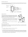
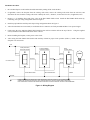
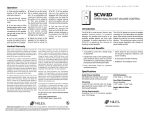
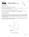
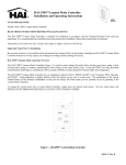
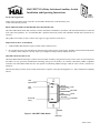
HAI UPB™ 15A Relay Switch and Auxiliary Switch
Installation and Operating Instructions
For the following Models:
40A00-1 HAI 15A Relay Switch (referred to as HAI UPB™ Wall Switch, in this document), and
37A00-1 HAI Auxiliary Switch
READ THESE INSTRUCTIONS BEFORE INSTALLING DEVICE
This HAI UPB™ Wall Switch and Auxiliary Switch is intended for installation in accordance with the National Electrical Code and
local codes and regulations. It is recommended that a qualified electrician perform this installation. Retain these instructions for
reference.
This product is for indoor use only. Connect only copper or copper clad wire to this device.
Important Notes Prior To Installation
1.
All HAI UPB™ Wall Switches require a neutral (white) connection wire.
2.
Be sure that all power to the load has been disconnected by turning off the circuit breaker. Installing an HAI UPB™ Wall Switch
or Auxiliary Switch with power on may expose you to dangerous voltage and may damage the device.
HAI UPB™ Wall Switch Overview
The HAI UPB™ Wall Switch (Figure 1) allows for local control of loads by using the Decora-style rocker switch. It also incorporates
the UPB™ two-way powerline communication technology that gives it the ability to be remotely controlled by UPB™ compatible
controllers. The HAI UPB™ Wall Switch is also capable of transmitting UPB™ messages when the rocker switch is turned on or
turned off.
The HAI 15A Relay Switch is used to control loads such as receptacles, motor-operated appliances (i.e. fans), and fluorescent lighting
fixtures.
LED
INDICATOR
TOP
(ON)
BLACK
WHITE
RED
BOTTOM
(OFF)
YELLOW
LINE
NEUTRAL
LOAD
CONTROL
GREEN
Figure 1 - HAI UPB™ Wall Switch
GROUND
40I00-1, Rev B
HAI Auxiliary Switch Overview
The 37A00-1 HAI Auxiliary Switch (Figure 2) is an optional companion device used with the HAI UPB™ Wall Switch for multi-way
circuits. The HAI Auxiliary Switch has a Decora-style rocker switch that controls the load in the exact same manner as the Decorastyle rocker switch on the HAI UPB™ Wall Switch.
LED
INDICATOR
TOP
(ON)
BLACK
GRAY
BLUE
BOTTOM
(OFF)
YELLOW
LINE
*NEUTRAL
(FOR RED INDICATOR)
*NEUTRAL
(FOR BLUE INDICATOR)
CONTROL
Figure 2 – HAI Auxiliary Switch
Changing Switch Color
The color of the HAI UPB™ Wall Switch and Auxiliary Switch may be changed to
complement the interior décor. The HAI UPB™ Wall Switch and Auxiliary Switch
is supplied with a white switch plate. Additional colors are available; contact your
HAI distributor for more information. When changing the switch plate, make sure
that the switch is disconnected from all power, and proceed as follows:
1.
The switch plate attaches to the HAI UPB™ Wall Switch and Auxiliary Switch
with two latches on the right and two on the left. Using a small-bladed
screwdriver, gently depress the upper and lower latch on one side while lifting
up on the plate. Once the latches are released on one side, remove the switch
plate from the other side.
2.
Align the latches of the new switch plate to the openings on the mounting plate
and gently snap into place.
Figure 3 – Changing Switch Color
INSTALLATION INSTRUCTIONS
The HAI UPB™ Wall Switch is wired directly to the load and can be controlled by adding one or more optional HAI Auxiliary
Switches producing multi-way circuits. Multi-way circuits make it possible for a group of switches to control the same load. This
section will illustrate how to make the connections.
Notes:
1.
Refer to Figures 1 and Figure 2 to determine the wire colors for each connection.
2.
All HAI UPB™ Wall Switches require a neutral (white) connection.
3.
The Line (black) wire must be accessible for the installation of all HAI Auxiliary Switches. This wire may be connected to either
phase of the 120/240V supply. The blue and/or gray wire on the HAI Auxiliary Switch can be connected to either earth ground or
neutral. The blue and/or gray wire is only used to light the LED on the switch. This LED only indicates that power is applied and
serves as a night-light. Connect the blue wire only to light the LED blue. Connect the gray wire only to light the LED red.
Connect both the blue wire and the gray wire to light the LED magenta.
Installation Procedure
1.
Be sure that all power to the load has been disconnected by turning off the circuit breaker.
2.
If applicable, remove the faceplate from the existing wall switch, remove the existing wall switch from the wall box, and
disconnect the wires from the existing wall switch. Identify the “Line”, "Neutral", "Load" and “Traveler” (if applicable) wires.
3.
Remove ¾” of insulation from each of the wires on the HAI UPB™ Wall Switch. Install the HAI UPB™ Wall Switch by
connecting wires per wiring configuration shown in Figure 5.
4.
Install any optional HAI Auxiliary Switch per wiring configuration shown in Figure 5.
5.
After all connections have been made, be certain that all wire connectors are firmly attached and there is no exposed copper.
6.
Gently place the wires and HAI UPB™ Wall Switch into the wall box with the LED at the top of device. Using the supplied
screws, attach the HAI UPB™ Wall Switch to the wall box.
7.
Before installing the faceplate, restore power to the circuit.
8.
After testing the HAI UPB™ Wall Switch and Auxiliary Switch for proper local operation (Table 1), install a Decora-style
faceplate over each switch.
LINE
37A00 (OPTIONAL)
AUXILIARY SWITCH
37A00 (OPTIONAL)
AUXILIARY SWITCH
BLACK
40A00
HAI Relay Switch
BLACK
YELLOW
LOAD
BLACK
YELLOW
YELLOW
Line 120VAC, 60Hz
WHITE
*BLUE AND/OR GRAY
*BLUE AND/OR GRAY
RED
GREEN
NEUTRAL
*CONNECTING THE BLUE AND/OR GRAY WIRE TO NEUTRAL SETS THE COLOR OF THE LED INDICATOR.
CONNECT BLUE FOR BLUE INDICATOR, GRAY FOR RED INDICATOR, OR BOTH FOR MAGENTA INDICATOR.
BLUE AND/OR GRAY WIRE MAY BE CONNECTED TO NEUTRAL OR EARTH GROUND. NEUTRAL IS RECOMMENDED.
Figure 4 – Wiring Diagram
HAI 15A RELAY SWITCH OPERATION
The HAI 15A Relay Switch has configurable items that can be set using the UPB™ UPStart configuration software. The following
describes the operation of the HAI 15A Relay Switch in its factory default configuration.
Local Rocker Switch Operation
The HAI 15A Relay Switch has a Decora-style rocker switch that can be used to control the load as follows.
Rocker Event
Single-Tap
Top Rocker
Load turns on.
Bottom Rocker
Load turns off.
Table 1 - HAI UPB™ 15A Relay Switch Local Operation
LED Indicator
The HAI UPB™ Wall Switch comes equipped with a multi-color LED indicator that is normally lit to blue when the load is off. The
LED is off when the load is on.
If used, the LED in the HAI Auxiliary Switch is always lit.
HAI AUXILIARY SWITCH OPERATION
The HAI UPB™ Wall Switch can be connected to one or more HAI Auxiliary Switches producing multi-way circuits. Each HAI
Auxiliary Switch has a Decora-style rocker switch that controls the load in the exact same manner as the Decora-style rocker switch
on the connected HAI UPB™ Wall Switch, as previously described. When connected, the LED remains continually on at all times
while power is applied.
Setup Mode
To configure the HAI UPB™ Wall Switch using an HAI controller or a PC running the UPB™ UPStart configuration software, it
must be put into Setup Mode as follows:
Step
1
2
Operation
Tap the rocker switch quickly 5 times.
The HAI UPB™ Wall Switch will cycle the load one time and blink its LED blue to indicate that it is in Setup Mode.
Note: the switch will automatically exit Setup mode after 5 minutes.
Reset to Factory Default Settings
To reset the HAI UPB™ Wall Switch to factory default settings:
Step
1
2
3
4
5
Operation
On the HAI UPB™ Wall Switch that you want to reset to factory default, tap the rocker switch quickly 5 times.
The HAI UPB™ Wall Switch will cycle the load one time and blink its LED blue to indicate that it is ready to be reset.
Tap the rocker switch quickly 10 times to reset to factory default setting.
The HAI UPB™ Wall Switch will cycle the load one time and blink its LED red to indicate that it has been reset.
Tap the rocker switch once more to stop the LED from blinking.
SPECIFICATIONS
Model Number
Incandescent Loads, Inductive Loads, and Florescent Loads
Motor-Operated Appliances
Current Maximum
Connections
LED Indicator
Dimensions
Weight
Mounting
Input Power
Input Frequency
Operating Temperature
40A00-1
Yes
Yes
15A
18 GA
Yes
4.1 x 1.75 x 1.45
0.25 lb.
Standard J Box
120 ± 12 VAC
60 ± 3 Hz
-40 °F to 104 °F
Note: It is normal for this switch to make a slight buzzing sound during operation. It is also normal for the switch and wall plate to
feel warm to the touch.
LIMITED WARRANTY
HAI warrants this product against defects in material and workmanship, under normal use and service, for a period of two (2) years from the date of
purchase. During the warranty period, HAI will repair or replace, at its sole option, if this product fails due to defect. This warranty does not cover the
cost of removal or reinstallation of any product. This warranty does not cover failure caused by normal wear, damage to the product while in
your possession (other than damage caused by defect or malfunction), or by its improper installation, including failure to follow the written
installation and operation instructions, alterations, misuse, or abuse. The remedies provided for in this warranty are the sole and exclusive
remedies thereof. In no event shall HAI be liable for incidental expenses or consequential loss or damages. For the complete HAI Warranty for USA
policy, see the HAI web site at www.homeauto.com.
Any implied warranties, including warranties of merchantability and fitness for particular use or purpose are limited to a period of two (2)
years from purchase date. This warranty gives you specific legal rights, and you may have other legal rights, which vary from state to state. Some
limitations may not apply to you.
For warranty and repair service within the continental United States, send defective unit carefully packaged, postage prepaid, along with description of
trouble, name, return address, and phone number to: HAI, Repair Department, 4330 Michoud Blvd, New Orleans, LA, 70129. HAI will pay return
shipping charges via normal ground service.
Outside of the continental United States: Contact an Authorized Distributor for repair/replacement instructions.