1
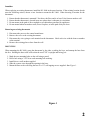
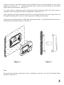
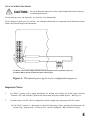
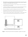
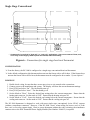
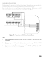
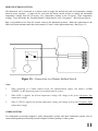
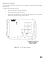
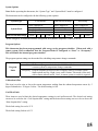
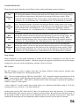
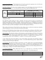
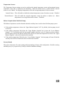
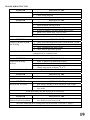
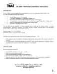
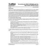
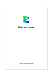
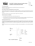
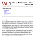
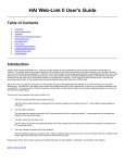
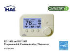
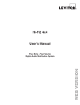
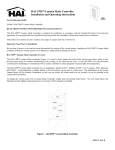
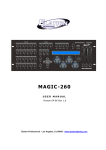
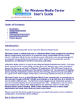
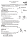
RC-1000 Thermostat Installation Instructions DESCRIPTION The RC-1000 is a precision digital thermostat designed for 24 VAC heating and cooling systems. The RC-1000 will support the following systems: Single Stage Heat/Cool Conventional Heat Pump (2 Stage Heat / 1 Stage Cool) Dual Fuel Heat Pump (2 Stage Heat / 1 Stage Cool) The RC-1000 has the capability of being controlled both locally and by remote control. It offers programmability, stand-alone operation, and robust, optically isolated communications with automation systems, utility control systems, and personal computers. Electrical rating: 24 V; 2 A; 50/60 Hz Maximum current: 2 A on any circuit, 3 A total The following requirements must be observed for installation in Europe: CE 1. This equipment must be installed in accordance with National wiring rules for the country in which it is installed. 2. All product labels, instructions and markings relating to safety must be translated to a language, which is acceptable in the country in which this equipment is to be installed. INSTALLATION Before installing this thermostat: 1. 2. 3. 4. 5. 6. Read all of the Installation Instructions carefully. Read the Owner's Manual carefully. Ensure that this product is suitable for your application. Ensure that wiring complies with all codes and ordinances. Disconnect power to the control transformer to prevent electrical shock and damage to equipment. Select an appropriate location to ensure an accurate temperature reading. Document Number 65I00-1 / Rev B / February, 2010 Copyright 2008-2010 Home Automation, Inc. All Rights Reserved 1 Location When replacing an existing thermostat, install the RC-1000 in the same location. If the existing location doesn't meet the following criteria, choose a new location to mount the RC-1000. When choosing a location for the thermostat: 1. 2. 3. 4. Ensure that the thermostat is mounted 5 feet above the floor and is at least 2 feet from an outdoor wall. Ensure that the thermostat is located in an area where there is adequate air circulation. Do not mount in the path of direct sunlight or of radiant heat generated by appliances. Do not mount behind an outdoor wall, near a fireplace, or in the path of any air ducts. Removing an existing thermostat 1. Disconnect the power to the control transformer. 2. Remove the cover to the existing thermostat. 3. Disconnect the wires going to each terminal on the thermostat. Label each wire with the letter or number at the terminal. 4. Remove the existing plate or base from the wall. MOUNTING When mounting the RC-1000, grasp the thermostat by the sides, avoiding the keys, and unsnap the base from the face. Holding the base to the wall so that the word "UP" is upright and facing you: 1. 2. 3. 4. 5. Mark the two mounting holes on the wall using a pencil. Drill a hole using a 3/16" bit at each mounting hole marking. Install the two wall anchors supplied. Slide the system wires through the opening in the base. Mount the base to the wall using the two #6 x 1/2" self-tapping screws supplied - See Figure 1. Figure 1 2 Connect each wire to the terminal strip(s) on the thermostat base per the wiring diagram for your system application - See Figures 4 - 7. Form the thermostat wiring so that the cable lies flat between the terminal strip(s) and the center of the base - See Figure 2. If a remote system or temperature sensor is being used with the thermostat, connect the remote system or temperature sensor wiring per the diagram for the application - See Figures 8 - 11. Upon completion of wiring the thermostat, push all excess wiring into the hole in the wall. Plug the hole with the supplied insulating foam to ensure an accurate temperature reading by the thermostat. Align the tabs of the thermostat face with the slots of the thermostat base. Gently push the thermostat face into the thermostat base locking it into place - See Figure 2. Slot Base Tab Temperature Sensor Wall Figure 2 Figure 3 Note: Be sure that the thermostat temperature sensor is standing up, and that it has not been damaged during installation - See Figure 3. 3 TYPICAL WIRING DIAGRAMS CAUTION: Be sure to disconnect the power to the control transformer before removing or installing thermostat. Do not short gas valve, fan, heat relay, or cool relay...even momentarily. Do not attempt to hook up to live circuits. An accidental connection to a component on the thermostat circuit board could cause damage to the thermostat. UP JUMPER 3 2 1 24VAC Common 24VAC "HOT" (C) (RC) THERMOSTAT 24VAC CONTROL TRANSMFOMER For HVAC systems with a single transformer, the metal jumper between Terminal 1 (RC) and Terminal 2 (RH) on the left terminal strip must remain in place. Figure 4 – Thermostat power-up for test or configuration purposes Important Notes: 1. For HVAC systems with a single transformer for heating and cooling, the metal jumper between Terminal 1 (RC) and Terminal 2 (RH) on the left terminal strip must remain in place – See Figure 4. 2. From the factory, the RC-1000 is configured to control a single stage conventional HVAC system. If the HVAC system is a heat pump or dual fuel heat pump, before operating the thermostat, the “System Type” settings under “System Options” must be configured – See Installation Settings. 4 3. When configured as a conventional thermostat, by default this thermostat does not turn the fan on with a call for heat. If the furnace requires the thermostat to turn the fan on with a call for heat, configure the “System Mode” to “Fan On With Heat” under “System Options”. 4. A conventional thermostat can be configured for automatic changeover heat/cool, manual changeover heat/cool, heat only, or cool only thermostat. 5. To disable the Task Buttons and Scroll Wheel to prevent local control of the thermostat, the buttons jumper (J6) labeled “BUTTONS” on the thermostat printed circuit board must be removed. 6. Refer to the “Configuration” steps under the wiring diagram for the respective HVAC system type. 7. If the thermostat or HVAC system does not perform as stated in the “Power Up” steps under the wiring diagram for the respective HVAC system, recheck all wiring - See Troubleshooting Tips. 8. For HVAC systems with separate heating and cooling transformers, the metal jumper between Terminal 1 (RC) and Terminal 2 (RH) on the left terminal strip must be removed – See Figure 5. UP REMOVE JUMPER 3 2 1 24VAC Common 24VAC HEAT TRANSMFOMER (C) 24VAC Heat "HOT" (RH) 24VAC Cool "HOT" (RC) THERMOSTAT 24VAC COOL TRANSMFOMER For HVAC systems with separate heating and cooling transformers, the metal jumper between Terminal 1 (RC) and Terminal 2 (RH) on the left terminal strip must be removed. Figure 5 – Connections for heat and cool transformers - applies to all systems 5 Single Stage Conventional UP HVAC SYSTEM 8 7 6 Fan (G) Fan Relay Cool (Y1) Cool Relay Heat (W1) Heat Relay 3 24VAC Common* 1 24VAC "HOT" (C) (RC) THERMOSTAT 24VAC CONTROL TRANSMFOMER * Common wire is required in “heat only” or “cool only” applications. Also use a common if heat, cool, or fan relay cannot supply 15mA to power thermostat, without activating. Figure 6 – Connections for single stage heat/cool thermostat CONFIGURATION From the factory, the RC-1000 is configured as a single stage conventional heat/cool thermostat. In the default configuration, this thermostat does not turn the fan on with a call for heat. If the furnace does not turn the fan on with a call for heat, the thermostat must be configured to do so under “System Options”. POWER UP 1. 2. 3. 4. 5. Double check wiring, be sure that there are no stray wires or wire strands at the connections. Connect power to the transformer and system. The display will show the current thermostat settings. Press [FAN] and select “On”. The fan should come on. Press [FAN] and select “Auto”. The fan should go off. Set the Mode to "Heat". Raise the desired heat setting above the current temperature. Ensure that the heating unit comes on. Set the mode to "Off". Ensure that the heating unit goes off. 6. Set the Mode to "Cool". Lower the desired cool setting below the current temperature. Ensure that the cooling unit comes on. Set the mode to "Off". Ensure that the cooling unit goes off. The RC-1000 thermostat is designed to work with most single state conventional 4-wire HVAC systems (without a transformer common). However, if the RC-1000 “resets” when calling for heat or cool, or if the heat, cool, or fan relay cannot supply 15mA to power thermostat without the relay activating, the transformer common wire or the HAI Thermostat Power Supply Module (Part Number: 30A00-1) is required. 6 About Heat Pump Systems 1) Terminal 5 (O) is energized for cooling Terminal 6 (B) is energized for heating In most applications, the reversing valve is energized for cooling and should be connected to the "O" terminal. If the heat pump requires the reversing valve to be energized for heating, connect the reversing valve to the "B" terminal. 2) To temporarily disable Energy Efficient Control and heat as quickly as possible, press [HOLD] and select “On”. The RC-1000 will use the Auxiliary Heat as needed to reach the heat setting. 3) Terminal 9 (L) is used to indicate a fault with the heat pump compressor. When there is a compressor fault, the display will flash red and the “Heat Pump Fault” error message is shown. 4) The Emergency Heat Relay (E Terminal) and outdoor thermostats (usually accessories to a heat pump), are not used. The RC-1000 automatically controls auxiliary heat efficiently. If the heat pump is equipped with an outdoor thermostat, it should be removed from the auxiliary heat circuit. About Dual Fuel Heat Pump Systems A dual fuel heat pump typically has a gas furnace combined with a heat pump. The gas furnace is used as auxiliary heat unless the outdoor temperature is very low, in which case it is used as the primary heat source. 1) When used with dual fuel heat pumps, the RC-1000 requires a method for obtaining the outdoor temperature. A temperature sensor can be physically connected to the “Remote Temp. Sensor” terminals on the thermostat or the RC-1000 can obtain the outdoor temperature from a remote system. If the RC-1000 can not obtain the outdoor temperature, the heat pump compressor will not operate and the thermostat will only call for the auxiliary heat until the problem is resolved. When this occurs, the display will flash red and the “Problem With Outdoor Temperature Sensor. Some Heat Stages May Be Disabled” error message is displayed. After the error has been acknowledged, “Outdoor Sensor Fault” will be displayed in the Message Bar until the problem is resolved. 2) Balance Setpoint Limits: If the outdoor temperature is above the “Upper Balance Setpoint” (45°F by default), the heat pump is used exclusively. If the outdoor temperature falls below the “Upper Balance Setpoint” but is above the “Lower Balance Setpoint” (35°F by default) and if the heat pump is unable to heat at a rate of 5 degrees per hour or better, the heat pump will turn off and auxiliary heat will be used until the call for heat has been satisfied. If the outdoor temperature falls below the “Lower Balance Setpoint”, the heat pump will turn off and the auxiliary heat will be used until the call for heat has been satisfied. The Balance Setpoint Limits can be adjusted according to the manufacturer’s specifications under “Balance Setpoint” – See Installation Settings. 3) When the RC-1000 makes a call for auxiliary heat, the heat pump compressor is turned off and the auxiliary heat is used exclusively. 7 Heat Pump (2 Stage Heat / 1 Stage Cool) UP 9 8 7 6 5 4 3 1 HVAC SYSTEM Ground Fault (L) Fault Relay Fan (G) Fan Relay Compressor (Y1) Compressor Relay Energized in Heat (B) Energized in Cool (O) Reversing Valve (W2) Aux Heat Relay Auxilirary Heat 24VAC Common 24VAC "HOT" (C) (RC) THERMOSTAT 24VAC CONTROL TRANSMFOMER Figure 7 – Connections for heat pump thermostat CONFIGURATION The “System Type” for this thermostat must be set to “Heat Pump” under “System Options”. The “System Type” for this thermostat must be set to “Dual Fuel Heat Pump” for a dual fuel system (Terminal “W2” is connected to the “W” or “W1” on the furnace). POWER UP 1. 2. 3. 4. 5. 6. Double check wiring, be sure that there are no stray wires or wire strands at the connections. Connect power to the transformer and system. The display will show all of the thermostat settings. Press [FAN] and select “On”. The fan should come on. Press [FAN] and select “Auto”. The fan should go off. Press [HOLD] and select “On” to override Energy Efficient Control. Set the Mode to "Heat". Raise the desired heat setting 1 degree above the current temperature. Ensure that the heat pump comes on, in heating mode. After a few minutes, raise the desired heat setting 3 degrees above the current temperature. Auxiliary heat should come on. After a few minutes, set the mode to "EM Heat". The heat pump should stop but the auxiliary heat should remain on. Set the mode to “Off”. Ensure that both the heat pump and auxiliary heat go off. 7. Set the Mode to "Cool". Lower the desired cool setting below the current temperature. Ensure that the heat pump comes on, in cooling mode. Set the mode to "Off". Ensure that the cooling unit goes off. 8. Press [HOLD] and select “Off” to enable Energy Efficient Control. 8 REMOTE SYSTEM WIRING DIAGRAMS This thermostat has been preprogrammed with energy saving program schedules. When used with a remote system, HAI recommends that the Program Mode be configured as “None” or “Occupancy”. This will disable the internal program schedules. SETTING THE COMMUNICATIONS JUMPER This thermostat comes from the factory with the communications jumper (J8) labeled “COMM JUMPER” on the thermostat printed circuit board installed - See Figure 8. When connecting to an HAI Home Control system or remote switch, this jumper must be installed. When connecting to a PC or other device with a serial port, this jumper must be removed. COMM JUMPER J8 COMMUNICATIONS JUMPER FIGURE 8 – COMMUNICATIONS JUMPER 9 HAI HOME CONTROL SYSTEMS The thermostat can be connected to an HAI Home Control system. The controller can send commands to the thermostat to change mode, cool setting, heat setting, status of fan and hold, and other items. Run a 3 (or 4) conductor wire from the HAI system to the thermostat location. All thermostats on an HAI Home Control system are connected to Ground, Zone +16, and Output 8 - See Figure 9. CONTROLLER THERMOSTAT UP Black Green Yellow Communication Jumper Figure 9 – Connections to HAI Home Control System Notes: 1. Additional thermostats are connected in parallel. They may be connected in home-run or daisy chain configuration. 2. When connecting to an HAI Home Control System, the communications jumper (J8) labeled “COMM JUMPER” on the thermostat printed circuit board must be in place. 3. All thermostats on an OmniLT controller are connected to the GRN (Green), BLK (Black), and YEL (Yellow) terminals under the section marked "TSTAT". 10 REMOTE SETBACK SWITCH The thermostat can be connected to a remote switch to toggle the desired heat and cool temperature settings between preset setpoints. A signal can be sent from the remote switch location to change the thermostat temperature settings from the Occupancy Day temperature settings to the Occupancy Night temperature settings. To use this mode, the “Program Options” setting must be set to “Occupancy” - See Program Options. Run a two-conductor wire from the remote switch to the thermostat location. Make the connections to the Black and Green terminals under the section marked “Comm” on the right terminal strip - See Figure 10. ANY SYSTEM WITH A RELAY OR 5 - 15 VDC OUTPUT THERMOSTAT UP Black Green 5 -15 VDC Communication Jumper Figure 10 – Connections to a Remote Setback Switch Notes: 1. When connecting to a remote setback switch, the communications jumper (J8) labeled “COMM JUMPER” on the thermostat printed circuit board must be in place. 2. When 0VDC is applied, the desired temperature settings will change to the preset Occupancy Day temperature settings. 3. When 5-15VDC is applied, the desired temperature settings will change to the preset Occupancy Night temperature settings. OTHER SYSTEMS For connections to personal computers, utility management systems, and other automation systems, refer to connection diagrams provided with personal computer software package or other system. 11 REMOTE TEMPERATURE SENSOR A remote temperature sensor can be installed to monitor the temperature from a remote location or can be combined with the onboard temperature sensor for the average temperature of two locations. Run a twisted pair, shielded cable from the RC-1000 to the remote temperature sensor location. For distances up to 100 feet, typical twisted pair, PVC-insulated, shielded cable may be used. For distances from 100-150 feet, twisted pair with polypropylene insulated conductors, shielded must be used. For distances from 150-250 feet, twisted pair with foam-polyethylene insulated conductors, shielded must be used. Wire runs must not exceed 250 feet. Make the connections to the Green and Black terminals under the section marked “Remote Temp Sensor” on the right terminal strip - See Figure 11. THERMOSTAT UP Green Black Communication Jumper Figure 11 – Connections to a Remote Temperature Sensor Notes: 1. When connecting a remote temperature sensor, the shield and one of the wires from the remote temperature sensor are tied together and get connected to the Black terminal – See Figure 11. 2. At the location of the temperature sensor, wrap the shield around the jacket of the cable and tape. 3. Configure the temperature sensor according to the application – See “Temperature Sensors” under Installation Settings. 12 DISABLE LOCAL CONTROL The Task Buttons and Scroll Wheel on the thermostat can be disabled to prevent anyone from controlling the thermostat locally. To disable the Task Buttons and Scroll Wheel: 1. Remove the thermostat face from the thermostat base. 2. Remove the local control jumper - See Figure 12. 3. Align the tabs of the thermostat face with the slots of the thermostat base. Gently push the thermostat face into the thermostat base locking it into place. COMM JUMPER J8 TO DISABLE TASK BUTTONS AND SCROLL WHEEL REMOVE JUMPER Figure 12 – Local Control Jumper 13 SETUP AND CONFIGURATION NOTE: For proper operation of the features of this thermostat, the Time and Date must be set. Even when connected to an HAI controller which sets the time and day, the Date must be manually set in the thermostat under the “Settings” menu. INSTALLATION SETTINGS This section describes the items that the installer must setup as part of the thermostat installation. The Installation Settings menu is used to configure the operating parameters of the thermostat. To access the Installation Settings mode: 1. 2. 3. 4. 5. 6. 7. From the Home Page, press the Scroll Wheel. Turn the Scroll Wheel until “Setup” is highlighted. Press the Scroll Wheel or [Select] to select “Setup”. Turn the Scroll Wheel until “Installation Settings” is highlighted. Press the Scroll Wheel or [Select] to select “Installation Settings”. Read the warning and then press [Continue] to proceed. To exit Setup mode, press [Back] several times until the Home Page is displayed. Notes: 1. 2. 3. The thermostat will automatically default to the Home Page after 3 minutes of no key activity. The word "default" indicates the initial setting when the thermostat is delivered from the factory. Unless otherwise noted, an asterisk (*) next to a setup item indicates the default setting. Thermostat Address If you are using remote communications and you are installing more than one thermostat, each must be set to a unique address. The default address setting is 1. An address from 1- 127 may be selected. Communications Mode The thermostat can communicate with remote systems in different modes. The following modes are available: Communications System Baud Expansion Baud *Serial: RS-232 mode for use with personal computers and automation systems. Day/Night: The thermostat remotely communicates with a remote setback switch. *100 300 1200 2400 9600 100 300 *1200 2400 9600 14 System Options Note: Before operating the thermostat, the “System Type” and “System Mode” must be configured. The thermostat can be configured with the following system options: System Mode Fan On with Heat Stage 1 Dual Fuel Heat Pump1 *Conventional System Type *Auto Changeover Manual Changeover Heat Only Cool Only *None 1 2 Auto Changeover Manual Changeover 1 and 2 1 2 1 and 2 Heat Pump Auto Changeover Manual Changeover 1 2 1 and 2 When configured, an additional Installer Setup menu item (Balance Setpoints) is added to the list. Program Options This thermostat has been preprogrammed with energy saving program schedules. When used with a remote system, HAI recommends that the Program Mode be configured as “None” or “Occupancy”. This will disable the internal program schedules. The program options setting sets the method for scheduling temperature change commands. Program Mode *Schedule: Program setpoints are based on time of day and day of week. None: The internal program schedule is disabled. Use this when connected to a remote system for temperature change commands. Occupancy: Program setpoints are based on the occupancy status of a remote system. Status options are Day, Night, Away, and Vacation. This mode is also used with a remote setback switch. Note: A remote system or switch is required. Calibration Offset This item is used to raise or lower the current temperature reading from the onboard temperature sensor by .5 degree Fahrenheit or .25 degree Celsius. The default setting is 0.00. Cool/Heat Limit These items are used to limit the desired temperature settings in cool and heat mode. The desired cool setting can never be set below the “Cool Setpoint Min” setting and the desired heat setting can never be set above the “Heat Setpoint Max” setting. The default setting for cool is 51°F. The default setting for heat is 91°F. 15 Cool/Heat Min On/Off These items are used to limit the on and off times of the cooling and heating system (in minutes). Cool Minimum On Cool Minimum Off Heat Minimum On Heat Minimum Off The number of minutes the thermostat forces the cooling system to remain on before turning off. Raising this number will increase the total time the cooling system is on (saving energy), but may allow the temperature to drift farther from setpoint (decreasing comfort). When combined with Cool Minimum Off, cycles per hours can be obtained by using the following calculation: 60 / (Cool Minimum On + Cool Minimum Off). The default time is 6 minutes. The number of minutes the thermostat forces the cooling system to remain off before starting again. Raising this number will increase the total time that the cooling system is off (saving energy), but may allow the temperature to drift farther from the setpoint (decreasing comfort). When combined with Cool Minimum On, cycles per hours can be obtained by using the following calculation: 60 / (Cool Minimum On + Cool Minimum Off). The default time is 6 minutes. The number of minutes the thermostat forces the heat to remain on before turning off. Raising this number will increase the total time the heating system is on (saving energy), but may allow the temperature to drift farther from the setpoint (decreasing comfort). When combined with Heat Minimum Off, cycles per hours can be obtained by using the following calculation: 60 / (Heat Minimum On + Heat Minimum off). The default time is 6 minutes. The number of minutes the thermostat forces the heat to remain off before starting again. Raising this number will increase the total time that the heating system is off (saving energy), but may allow the temperature to drift farther from the setpoint (decreasing comfort). When combined with Heat Minimum On, cycles per hours can be obtained by using the following calculation: 60 / (Heat Minimum On + Heat Minimum off). The default time is 6 minutes. Stage Settings When configured as a heat pump thermostat, by default the RC-1000 is configures for two states of heat (auxiliary heat is included in this number). If the heat pump is not equipped with auxiliary heat, the Heat Stages setting may be set to one (in this configuration, auxiliary will never be used). EEC Control The EEC Settings are used to configure Heat and Cool Energy Efficient Control and the Auxiliary Heat Differential (when configured as a heat pump thermostat). EEC: This item configures Energy Efficient Control (EEC). EEC continually monitors the performance of the HVAC system and uses a PID algorithm and auto balance routine to achieve comfort while saving energy. A setting of 0 will disable EEC. When EEC is disabled, the RC-1000 will attempt to maintain the temperature within 0.5 degrees F of the setpoint. A lower setting of 2-3 can be used for slow reacting sources (e.g. radiant heat) and higher setting of 7-8 for fast reacting sources (e.g. forced air). The default setting is 5. On heat pump systems, EEC allows the RC-1000 to use auxiliary heat only when necessary. If it determines that the heat pump is able to heat at a rate of 5 degrees per hour or better, the auxiliary heat will not be used. If the heat pump is unable to heat at this rate, the thermostat will use the auxiliary heat as needed. Under these conditions, the heat pump will run continuously and the auxiliary heat will cycle on and off as needed. 16 Auxiliary Heat Differential: This determines how far from the setpoint the temperature has to be before the auxiliary heat turns on. This is only available for heat pump systems. Start Delay (Minutes): This item sets the minimum amount of time the heating system must run before the Auxiliary Heat Stage is used. To use this start delay, EEC must be enabled and Hold must be off. Conventional (1 Cool / 1 Heat) EEC Settings Heat EEC Cool EEC *5 *5 0 - 10 0 - 10 Heat Pump (1 Cool / 2 Heat) Dual Fuel Heat Pump (1 Cool / 2 Heat) Heat EEC *5 0 - 10 Cool EEC *5 0 - 10 Aux Heat Differential *2 1 - 10 Start Delay (Minutes) *5 0 - 4hr:15min Anticipator Control The Anticipator Control settings are used to “anticipate” the need to turn the system on or off before the temperature is actually at the setting. As humans, we perceive temperature as a combination of heat in the air and heat radiated from the walls and surroundings. The thermostat also measures a combination of air and wall temperature. When heating, the air temperature rises faster than the wall temperature. The thermostat will turn the heat off briefly to prevent overheating the air while the wall temperature catches up. When cooling, the thermostat will periodically run the cooling system to circulate the air and remove humidity when the temperature is close to, but not above the desired cool setting. Because of the PID algorithm and auto balance routine which monitors the performance of the HVAC system, the anticipator settings are automatic by default. However, the anticipator settings may be adjusted if desired. Heat Anticipator: This adjusts the tendency of the thermostat to turn the heating unit off before the desired heat setting is reached. This is done to avoid overheating the air while the walls and furniture catch up. A setting of 0-4 is intended for fast reacting heating systems, such as forced air. A setting of 6-10 is intended for slow reacting heating systems, such as radiant heat. A setting of 5 is used for automatic anticipation. A lower setting will decrease the tendency to turn off the heating system before the desired heat setting is reached. If the heating system response time is slower, as are most radiant heating systems, a higher number will help maintain an even space temperature. Cool Anticipator: This adjusts the tendency of the HVAC to run the cooling system to refresh and dehumidify the air before the temperature rises to the desired cool settings. A setting of 0-4 is intended for more humid climates and will increase the tendency for the cooling system to turn on to refresh and dehumidify the air. A setting of 6-10 is intended for dry climates and will decrease the tendency to run the cooling system below the cooling setting. A setting of 5 is used for automatic anticipation. 2nd/3rd Stage Extended On: When enabled and if any 2nd or 3rd stage turns on, it will remain on until the heat/cool is satisfied, regardless of the settings for any stage differentials. The default setting is off. Cool Anticipator Heat Anticipator 2nd/3rd Stage Extended On *5 *5 *Off 17 Temperature Sensors The Temperature Sensor settings are used to configure the internal temperature sensor and an optional remote temperature sensor that is connected to the thermostat. When the internal sensor is enabled and the external sensor is set to “Indoor”, the displayed temperature will be the average temperature of the two sensors. Internal Sensor: This will enable or disable the onboard temperature sensor for indoor use only. *Enabled External Sensor 1: This will enable the external temperature sensor for indoor or outdoor use. Indoor temperatures are averaged between the sensors. *Disabled Balance Setpoints (Dual Fuel Heat Pump) The Balance Setpoints are used to determine when the auxiliary heat is used in a dual fuel heat pump system If the outdoor temperature is above the “Upper Balance Setpoint” (45°F by default), the heat pump is used exclusively. If the outdoor temperature falls below the “Upper Balance Setpoint” but is above the “Lower Balance Setpoint” (35°F by default) and if the heat pump is unable to heat at a rate of 5 degrees per hour or better, the heat pump will turn off and the auxiliary heat will be used until the temperature rises above the “Upper Balance Setpoint” or the call for heat has been satisfied. If the outdoor temperature falls below the “Lower Balance Setpoint”, the heat pump will turn off and the auxiliary heat will be used until the call for heat has been satisfied. Factory Default This option will restore all system settings and programming to factory fresh configuration. Read the warning and then press [Yes] to proceed or [Cancel] to return to Installation Settings. 18 TROUBLESHOOTING TIPS SYMPTOM Thermostat Dead SYMPTOM Heat Or Cool Inoperative 1. 2. ACTION TO TAKE Check power to the thermostat Check wiring diagrams 1. 2. 3. 4. 5. 6. ACTION TO TAKE Check for break in W or Y wire Allow minimum off time to pass Check system options for correct settings If arrow is blinking, wait until startup delay expires Mode is Off (Select Heat, Cool, or Auto) Remote system is overriding thermostat SYMPTOM Control By Remote System Not Working ACTION TO TAKE 1. Check wires and connections to the section marked “Comm” 2. Check thermostat address setting 3. Check communications mode setting 4. Check setup of the remote system Ensure that all setup items for the thermostat and the remote system are set to the proper configurations for communication SYMPTOM Temperature Reading Incorrect 1. 2. ACTION TO TAKE Allow 30 minutes for thermostat to adjust. Adjust calibration offset Change setup option to display oF or oC 3. After installation, allow the thermostat up to 30 minutes for an accurate temperature reading SYMPTOM Display Problem 1. ACTION TO TAKE Cycle power to the thermostat (R). SYMPTOM Aux Heat On Too Often ACTION TO TAKE 1. Heat Pump is not able to meet load due to cold weather 2. Thermostat is in EM Heat mode – Set thermostat to Heat or Auto mode In EM Heat mode, only the auxiliary heat is turned on SYMPTOM ACTION TO TAKE Heat Pump Heats In Cool 1. Reversing valve is connected to wrong terminal - move Mode & Cools In Heat Mode wire from B to O or from O to B The wires connecting the reversing valve may be reversed - (See Note 1 - Page 7) 19 LIMITED WARRANTY HAI warrants this product against defects in material and workmanship, under normal use and service, for a period of two (2) years from the date of purchase. During the warranty period, HAI will repair or replace, at its sole option, if this product fails due to defect. This warranty does not cover the cost of removal or reinstallation of any product. This warranty does not cover failure caused by normal wear, damage to the product while in your possession (other than damage caused by defect or malfunction), or by its improper installation, including failure to follow the written installation and operation instructions, alterations, misuse, or abuse. The remedies provided for in this warranty are the sole and exclusive remedies thereof. In no event shall HAI be liable for incidental expenses or consequential loss or damages. For the complete HAI Warranty for USA policy, see the HAI web site at www.homeauto.com. Any implied warranties, including warranties of merchantability and fitness for particular use or purpose are limited to a period of two (2) years from purchase date. This warranty gives you specific legal rights, and you may have other legal rights, which vary from state to state. Some limitations may not apply to you. For warranty and repair service within the continental United States, send defective unit carefully packaged, postage prepaid, along with description of trouble, name, return address, and phone number to: HAI, Repair Department, 4330 Michoud Blvd, New Orleans, LA, 70129. HAI will pay return shipping charges via normal ground service. Outside of the continental United States: Contact an Authorized Distributor for repair/replacement instructions. 20