1
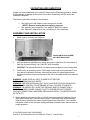
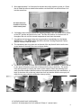
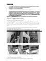
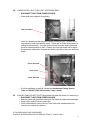
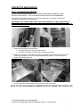
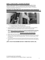
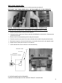
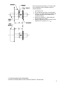
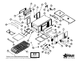
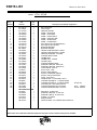
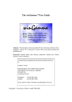
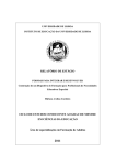
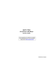
A Star Manufacturing Company
10 SUNNEN DRIVE, ST. LOUIS, MO/U.S.A. 63143
PHONE (314) 781-2777 FAX (314) 781-3636
HOLMAN CONVEYOR SANDWICH WARMER MANUAL
MODEL QT14
FOR SERVICE INFORMATION U. S. AND CANADA CALL:
TOLL FREE 1-800-807-9054
SUBJECT
TABLE OF CONTENTS
UNCRATING AND INSPECTION
ASSEMBLY AND INSTALLATION
OPERATION
BASIC CLEANING PROCEDURES
TROUGLESHOOTING
PREVENTATIVE MAINTENANCE & SCHEDULED CLEANING
• DAILY CLEANING
• WEEKLY BELT CLEANING
• MONTHLY CLEANING
• LONG TERM CLEANING
• REPLACING HEATER TUBES
• REPLACING COOLING FANS
• REPLACING BELT DRIVE MOTOR
WARRANTY PAGE
PARTS LIST AND HEATER TUBE LISTING
WIRING DIAGRAMS
PAGE
1
1&2
3
3&4
5&6
7&8
9
10 & 11
12
13 & 14
15
16 & 17
18
19 - 21
22 - 24
Certain Models
Electric Cooking Equipment for the Food Service Industry
Conveyor Toasters & Ovens Cheese Melters Broilers Pretzel Bakers
2M-HG0500
Rev C 2/22/06
Common Questions, Myths, and Misconceptions
of Holman Conveyor Ovens
Misconception:
Reality:
High Voltage (208v typical) is always the same.
An oven designed for 208v should operate from 208-215v. This range is
typical of local power grids and daily fluctuations. Some municipalities
operate at 220 and 240v which would require design variations. Improper
voltage can result in reduced control, performance, and reliability. Voltage
mismatches or daily fluctuations can be monitored for corrective action.
Misconception:
Reality:
The under-carriage of your oven is a safe haven for paper wraps and utensils.
The high-speed fan is the lungs of your oven. The oven has under-clearance
to maximize fan performance, cooling, safety, and reliability. Please
maximize the air-circulation to your fan and clean the debris on fan-grill
often. Note: Beware of paper and plastic wraps being drawn into fan-grill.
Misconception:
Reality:
Vent hoods can be hard-wired into the oven or to the same wall circuit.
Your conveyor oven can not support the current draw of the oven and a hood.
This practice will decrease performance and reliability as well as jeopardize
the Underwriter Laboratory’s safety certification. Please have a qualified
electrician wire your vent hood to a separate circuit.
Misconception:
Reality:
My conveyor oven is maintenance-free.
Proactive or preventive maintenance (PM) is the best way to protect against a
catastrophic failure (Murphy’s Law states: components will fail at peak
sandwich time). Maintenance provisions include heater-tubes, fan, chain,
belt, incoming power, lubrication, working and aesthetic surfaces, overall
cleanliness, and ventilation. Refer to weekly, monthly, and long-term
maintenance manuals for step-by-step instruction. Owning an emergency
repair kit is also recommended.
Misconception:
Reality:
My heater-tubes will last forever.
Your infra-red radiant style heating elements use a quartz sheath. They are
extremely effective and efficient in the bake, as well as producing quick risetime from cold start to full bake. However, just like a light bulb, quartz is
brittle and can break from jarring or careless maintenance. Long term
degradation of quartz also occurs from air borne sugars, salts, and debris
settling on the sheath. For consistent performance replace your tubes at
prescribed intervals.
“It’s what you learn after you know it all that counts.” -John Wooden
UNCRATING AND INSPECTION
Unpack unit and components from container. Remove all visible packing material, inspect
unit for damage. If damage is discovered, file a claim immediately with the carrier that
handled the shipment.
The following should be included in the container:
•
•
1ea. baking oven with heaters, and conveyor belt in place.
(NOTE): Remove heating element-shipping supports.
1ea. stainless steel unload tray, 1ea. stainless “Bake Aid” bracket
1ea. “Bake Aid” magnet label, 2ea. crumb trays & 4ea. metal legs.
ASSEMBLY AND INSTALLATION
1.
Attach legs by screwing into weld nuts.
ADJUSTABLE LEGS SCREW
INTO BOTTOM OF UNIT
2.
Anti Skid pads are available at no charge and may be adhered to the foot section of
each leg to prevent sliding. Call 1-800-807-9054 for details.
CAUTION: The National Sanitation Foundation does not approve use of these pads.
3.
Install unit in its operating position. The load & unload ends must be at least 6" from
any vertical combustible surfaces. Allow sufficient space for operating personnel.
Have an electrician connect input power to the unit in accordance with local electrical
codes.
WARNING: MAKE SURE ALL INPUT POWER IS OFF BEFORE
INSTALLING/REMOVING ANY PARTS.
WARNING: BEFORE INSTALLING UNIT, HAVE YOUR ELECTRICIAN CHECK WITH
LOCAL POWER COMPANY TO DETERMINE ACTUAL VOLTAGE AT JOB SITE.
WARNING: BE ABSOLUTELY SURE THE GROUND (EARTH) CONNECTION IS
PROPERLY WIRED. NEVER CONNECT UNIT TO POWER WITHOUT PROPER
GROUND CONNECTIONS. IMPROPER GROUND MAY RESULT IN SEVERE INJURY
OR FATALITY.
4. Before applying input power to the unit check heating elements for breakage. Do not
apply power to the unit if a broken tube is found. If no broken tubes are found apply
input power by switching the master On/Off toggle to the ON position. Turn conveyor
belt speed control to the maximum setting and check all heater tubes and conveyor for
proper operation.
IF FURTHER ASSISTANCE IS REQUIRED:
CONTACT STAR/HOLMAN FACTORY SERVICE TEAM AT 1-800-807-9054
1
5. Allow approximately 5 to 8 minutes for the twin-fan cooling system to come on. Check
the air intake fan area as noted below and be sure that there is a sufficient flow of air
into the control box.
Air intake areas are
located on each side
of the control panel.
6. If all heaters and conveyor system are operating properly, turn the master On/Off switch
to the OFF position and allow unit to cool. The fans will continue to circulate cool air
throughout the unit until the internal temperatures have been decreased.
7. If a problem is discovered during start up procedures, immediately turn the Master
On/Off switch to the OFF position and call the Holman Cooking Equipment Factory
Service Team at 1-800-807-9054.
8. The unload tray has a key-hole slot on the end of the tray that will slide over the two
screw heads on the end of the oven as shown below;
9. The crumb trays slide into each end of the warmer under the conveyor. A slot is formed
by two pieces of metal on each side of the area for the tray to slide into. The crumb
trays are important by keeping the interior of the machine clean and reflecting heat
away from the controls inside the bottom of the machine back up to the sandwiches. A
layer of aluminum foil on the tray (check that it will not interfere with the conveyor) will
make the tray more reflective and make cleanup quicker.
IF FURTHER ASSISTANCE IS REQUIRED:
CONTACT STAR/HOLMAN FACTORY SERVICE TEAM AT 1-800-807-9054
2
OPERATION
1.
Turn Master On/Off switch to the ON position and variable speed control to fastest
time setting. Allow 1 hour for complete machine warm up.
2.
Adjust speed control to desired speed.
3.
Adjust speed as required during operation to achieve a good bake.
4.
When done for the day, turn Master On/Off switch to the OFF position. The conveyor
will stop and the elements will go off. The two fans should continue to run. They are
controlled by a thermostat that will allow the fans to cool the machine. Do not begin
to service or clean the machine until the fans have stopped. CAUTION: Some parts
of the machine will still be warm.
Refer to the Troubleshooting section if the machine is not performing as expected.
BASIC CLEANING PROCEDURES
Preventive maintenance for your Holman oven consists of the following recommended
cleaning procedures. To keep your oven in its top operating condition, these steps should
be performed daily or weekly as indicated. Also refer to the Preventative Maintenance
section for more complete cleaning activities that should be performed on a less frequent
basis.
Turn power off and allow cooling fans to run until the control box is cooled off. The fans are
controlled by a thermostat in the control box.
DISCONNECT UNIT FROM POWER SUPPLY OR TURN POWER OFF AT WALL BREAKER. BE
SURE THE SANDWICH WARMER IS COMPLETELY COOLED BEFORE PERFORMING ANY OF THE
FOLLOWING PROCEDURES.
1.
Remove Unload Tray (daily) as shown and wash with hot, soapy water.
IF FURTHER ASSISTANCE IS REQUIRED:
CONTACT STAR/HOLMAN FACTORY SERVICE TEAM AT 1-800-807-9054
3
2.
Remove the Crumb Trays from both sides of the oven (daily) as shown below
(DO NOT CLEAN WITH CAUSTIC CLEANERS).
3.
For lightly soiled conveyor surfaces a damp cloth or scotch pad can be used without
removing the conveyor belt. (daily) For heavily soiled conveyor surfaces refer to the
Preventative Maintenance section for more detailed instruction to remove the
conveyor belt. The belt will need removed for more thorough cleaning.
4.
Check air intake area for dust and grease. To clean, vacuum and wipe with a dry
cloth. (daily) Do not spray cleaning fluids into the air intake. This may result in
component failure.
5.
Carefully remove and clean the Neo-ceram window. (daily) Remove the
thumbscrews securing the window ring. Remove the window ring, the glass retainer,
and the piece of glass. Wash with hot, soapy water.
WARNING: THE GLASS THAT IS SUPPLIED WITH THIS OVEN IS SPECIFICALLY
DESIGNED FOR IT. DO NOT SUBSTITUTE ANY OTHER GLASS PRODUCTS IN ITS
PLACE. NEVER OPERATE THE OVEN WITHOUT THE GLASS. NEVER ATTEMPT TO
TOUCH OR REMOVE THE GLASS WHILE THE OVEN IS HOT. ALLOW THE OVEN TO
COOL FOR SEVERAL HOURS BEFORE STARTING THE CLEANING PROCEDURE.
6.
Re-assemble unit and check to be sure it is operating properly. If assistance is
required contact the Star/Holman Factory Service Team at 1-800-807-9054 (24
hours/day 7days a week).
IF FURTHER ASSISTANCE IS REQUIRED:
CONTACT STAR/HOLMAN FACTORY SERVICE TEAM AT 1-800-807-9054
4
TROUBLESHOOTING GUIDE
#
UNIT WILL NOT HEAT, CONVEYOR BELT WILL NOT TURN.
o Be sure main circuit breaker is switched to the ON position.
o Check that the unit is connected to power and Master On/Off switch is ON.
o Be sure HEAT LIMIT SWITCH is pushed in (see below).
Heat Limit Switch
Crumb Tray Slots
#
UNIT WILL NOT HEAT, CONVEYOR TURNS.
o Check to see if the Master On/Off Switch is in the ON position.
o Press heat limit switch, located beneath the unload tray as shown above
Your Holman Conveyor Oven is equipped with an automatically activated HEAT
LIMIT SWITCH that interrupts the heater tube connections if the air temperature in
the control box exceeds 190°F (88°C). This limit switch can be reset manually by
pushing the button in the center of the switch that is located beneath the unload
tray.
THE HEAT LIMIT SWITCH CAN BE ACTIVATED IF THERE IS NOT A PROPER
AMOUNT OF AIR FLOW BEING GENERATED BY THE COOLING FANS. IF THIS
OCCURS:
•
•
•
•
DISCONNECT UNIT FROM POWER SOURCE.
Make sure the air intakes in the front of the unit are free of dust, grease or other
obstructions.
Make sure the crumb trays (heat reflectors) are in place (see photos this page
and page 2) NEVER OPERATE UNIT WITHOUT CRUMB TRAYS IN POSITION
AS THIS CAUSES OVERHEATING IN THE CONTROL BOX AND WILL SHUT
DOWN THE MACHINE.
If the outside of the air intakes is clear and the crumb trays are in place and the
unit continues to shut down because of the Heat Limit Switch, refer to the
cleaning instructions in the more complete Preventative Maintenance section.
A heavy buildup of dust and grease from the kitchen can cover parts inside the
control box area and cause overheating.
IF FURTHER ASSISTANCE IS REQUIRED:
CONTACT STAR/HOLMAN FACTORY SERVICE TEAM AT 1-800-807-9054
5
#
CONVEYOR WILL NOT TURN, UNIT HEATS PROPERLY
o DISCONNECT UNIT FROM POWER SOURCE
o Check both fuses (replace if necessary)
Twin Fuse Block
o Check for obstructions that may have caused a conveyor jam. Utensils, foil or
large pieces of food could stall the motor. If there are no visible obstructions, try
turning the belt manually. If the belt turns, remove the power supply panel and
check for loose sprockets or chain. Realign any loose sprockets and re-tighten
the setscrews making sure the setscrews seat on the flats of the motor and drive
shafts.
Driven Sprocket
Drive Chain
Driver Sprocket
o If further assistance is required, contact the Star/Holman Factory Service
Team at 1-800-807-9054 (24 hours/day 7days a week).
#
COOLING FANS DO NOT START (fans should start after the machine is warmed up)
o
o
o
o
DISCONNECT UNIT FROM POWER SOURCE
Remove panels with fan motors and check fan blades for obstructions/breakage.
Check motor cords for secure connection
Call the Star/Holman Factory Service Team, as the fan switches and/or fan
motor(s) may need to be replaced.
IF FURTHER ASSISTANCE IS REQUIRED:
CONTACT STAR/HOLMAN FACTORY SERVICE TEAM AT 1-800-807-9054
6
PREVENTIVE MAINTENANCE
DAILY CLEANING PROCEDURES
TO KEEP YOUR HOLMAN MODEL QT14 CONVEYOR SANDWICH WARMER AT PEAK
OPERATING EFFICIENCY, THE FOLLOWING INSTRUCTIONS ARE RECOMMENDED:
Turn power off and allow cooling fans to run until the control box is cooled off. The fans are
controlled by a thermostat in the control box.
DISCONNECT UNIT FROM POWER SUPPLY OR TURN POWER OFF AT WALL BREAKER. BE
SURE THE SANDWICH WARMER IS COMPLETELY COOLED BEFORE PERFORMING ANY OF THE
FOLLOWING PROCEDURES.
1. Remove the unload tray as shown below.
a. For lightly soiled tray, clean with a damp cloth.
b. For heavily soiled tray, use an abrasive pad and mild cleaner.
2. Remove crumb trays from beneath each end of conveyor belt and discard soiled aluminum foil.
If cleaning is necessary, use a wet cloth and mild detergent cleaner. Do not use a caustic
cleaner to clean the crumb tray.
3. Cover crumb tray with clean aluminum foil and return crumb tray to oven.
(NOTE: DO NOT RUN SANDWICH WARMER WITHOUT CRUMB TRAYS INSTALLED)
IF FURTHER ASSISTANCE IS REQUIRED:
CONTACT STAR/HOLMAN FACTORY SERVICE TEAM AT 1-800-807-9054
7
4. Wipe exterior of unit with a damp cloth.
5. Wipe fan grills/air intakes (located on side of the unit) to remove any dust build up using a damp
cloth. Reassemble unit making sure crumb trays are properly installed. The crumb tray should
slide into the slot on each side of the area under the belt.
6. Clean the viewing window by removing the six thumbscrews on the rear of the sandwich
warmer. Remove the window trim ring. Then remove the window spacer. Then carefully remove
the Neo-Ceram glass.
7. Clean the Neo-Ceram glass using the mild soap. DO NOT use any abrasive cleaner or scrub
pad. A scratched glass is more easily broken and will get dirtier faster.
8. Re-assemble the viewing window by carefully placing the Neo-Ceram glass back in. Place the
window spacer with the flanged side against the glass in. Line up the six holes of the window
trim ring with six holes on the side of the warmer and re-install the thumbscrews.
IF FURTHER ASSISTANCE IS REQUIRED:
CONTACT STAR/HOLMAN FACTORY SERVICE TEAM AT 1-800-807-9054
8
WEEKLY CONVEYOR BELT CLEANING PROCEDURES
TO KEEP YOUR HOLMAN MODEL QT14 CONVEYOR SANDWICH WARMER AT PEAK
OPERATING EFFICIENCY, THE FOLLOWING INSTRUCTIONS ARE RECOMMENDED:
Turn power off and allow cooling fans to run until the control box is cooled off. The fans are
controlled by a thermostat in the control box.
DISCONNECT UNIT FROM POWER SUPPLY OR TURN POWER OFF AT WALL BREAKER. BE
SURE THE SANDWICH WARMER IS COMPLETELY COOLED BEFORE PERFORMING ANY OF THE
FOLLOWING PROCEDURES.
1. Remove the unload tray as shown in daily cleaning instructions earlier.
a. For lightly soiled tray, clean with a damp cloth.
b. For heavily soiled tray, use an abrasive pad and mild cleaner.
2. Using a wire grill brush or dry abrasive pad, clean the exposed surface of Conveyor Belt by
passing the brush or pad, back and forth across the surface of the Conveyor Belt.
3. When a section of Conveyor Belt is clean, remove wire brush or abrasive pad from conveyor
surface. Reconnect power or turn power back on. Switch the ON/OFF switch to the ON position.
Allow the Conveyor Belt to advance to expose another section of belt surface. Switch the
ON/OFF Switch to the OFF position. Disconnect or turn power off at wall breaker.
4. Repeat steps 2 and 3 until the entire surface of the Conveyor Belt has been cleaned.
5. Remove Crumb Trays from beneath Conveyor Belt and discard the aluminum foil. If cleaning is
necessary, use a wet cloth and mild detergent cleaner. Do not use a caustic cleaner to clean
the crumb tray.
6. Cover Crumb Trays with clean aluminum foil (shiny side facing up) and return Crumb Trays to
Sandwich Warmer. The crumb tray should slide into the slot on each side of the area under the
belt.
(NOTE: DO NOT RUN WARMER WITHOUT CRUMB TRAYS INSTALLED)
IF FURTHER ASSISTANCE IS REQUIRED:
CONTACT STAR/HOLMAN FACTORY SERVICE TEAM AT 1-800-807-9054
9
MONTHLY CLEANING PROCEDURES
Turn power off and allow cooling fans to run until the control box is cooled off. The fans are
controlled by a thermostat in the control box.
DISCONNECT UNIT FROM POWER SUPPLY OR TURN POWER OFF AT WALL BREAKER. BE
SURE THE SANDWICH WARMER IS COMPLETELY COOLED BEFORE PERFORMING ANY OF THE
FOLLOWING PROCEDURES.
1. Working from the power supply side of the oven, locate the electrical box side panel. Remove
two screws holding panel in place and remove panel. Drive chain is now exposed.
2. Check drive chain tension.
a. When properly adjusted, chain will have about 1/8” play but will not sag.
b. To adjust drive chain tension remove power supply side panel and locate drive motor
mounting screws (located behind drive motor sprocket). Loosen screws holding drive
motor in place and slide drive motor forward or backward to adjust chain tension. With
proper chain tension, retighten motor screws.
c. Lubricate drive chain and sprocket teeth
with a high temp synthetic or graphite
based lubricant.
NOTE: WD-40 and similar lubricants are not
recommended. Using an extreme pressure,
synthetic chain lubricant with a temperature
range up to 400°F. Apply liberally onto
chain and sprockets. This grease is
available as part no. 1P-Z8914.
IF FURTHER ASSISTANCE IS REQUIRED:
CONTACT STAR/HOLMAN FACTORY SERVICE TEAM AT 1-800-807-9054
10
3. Clean air intake on the side of Sandwich Warmer by vacuuming any dust and debris built up on fan
grill.
4. Return unit to counter and remove screw holding power supply side panel in place. Carefully lift panel
up and out. Two ground straps hold panel to oven chassis. DO NOT REMOVE GROUND STRAPS
OR DISCONNECT POWER SUPPLY CORD. Vacuum any dust and debris from inside of unit
(repeat for opposite side).
5. Replace all panels when done. CHECK THAT ALL WIRES DO NOT GET PINCHED AS THE
PANELS ARE REPLACED. ALSO CHECK ANY WIRES AROUND THE MOTOR TO MAKE SURE
THEY DO NOT GET PUSHED INTO THE SPROCKETS. Mounting screws for panels should be
started by hand, and then tightened with a screwdriver.
6. For exterior portions of unit that are heavily soiled, an abrasive pad may be used for cleaning. Be
sure to pass the pad in the direction of the grain in the metal to maintain the surface’s finish. Lightly
soiled surfaces may be cleaned with a damp cloth and mild cleaner.
7. Reconnect unit to power supply and test for proper operation.
IF FURTHER ASSISTANCE IS REQUIRED:
CONTACT STAR/HOLMAN FACTORY SERVICE TEAM AT 1-800-807-9054
11
LONG TERM CLEANING PROCEDURES (every 6 months)
Turn power off and allow cooling fans to run until the control box is cooled off. The fans are controlled by a
thermostat in the control box.
DISCONNECT UNIT FROM POWER SUPPLY OR TURN POWER OFF AT WALL BREAKER. BE SURE THE
SANDWICH WARMER IS COMPLETELY COOLED BEFORE PERFORMING ANY OF THE FOLLOWING
PROCEDURES.
1. With the power off, allow the unit to cool completely. Place Sandwich Warmer on non-extension end.
Remove screws holding control box covers in place and remove.
NOTE:
TO PREVENT DAMAGE TO CONTROLS
OR ELEMENTS, DO NOT SET THE
MACHINE ON SIDE PANELS.
TO PREVENT DAMAGE TO
ACCESSORIES, REMOVE CRUMB
TRAYS AND UNLOAD TRAY BEFORE
LIFTING OVEN TO UPRIGHT POSITION
2.
3.
4.
5.
Remove screws holding control box covers in place and remove.
Using a vacuum, clean the inside of control box. Wipe any buildup that cannot be vacuumed with a dry towel.
Replace control box covers and fasten with screws. Put the machine back on its feet.
Remove side panels and vacuum compartments as performed under monthly cleaning procedures.
IF FURTHER ASSISTANCE IS REQUIRED:
CONTACT STAR/HOLMAN FACTORY SERVICE TEAM AT 1-800-807-9054
12
MAINTENANCE PROCEDURES
REPLACING HEATER TUBES
FOR BEST TOASTING PERFORMANCE, THIS PROCEDURE SHOULD BE DONE EVERY SIX MONTHS
Turn power off and allow cooling fans to run until the control box is cooled off. The fans are controlled by a thermostat in
the control box.
DISCONNECT UNIT FROM POWER SUPPLY OR TURN POWER OFF AT WALL BREAKER.
NOTE: PERFORM THIS MAINTENANCE ONLY WHEN THE
CONVEYOR SANDWICH WARMER IS COMPLETELY COOL.
1. Position unit for access to front and rear panels. Also remove the viewing window per instruction in daily cleaning.
2. Remove screws holding front and rear panels. Lift panels up and out to remove.
3. Each heater tube has its own connection to a terminal block at the front and back of the sandwich warmer.
NOTE: MARK WIRE LOCATIONS IN TERMINAL BLOCKS BEFORE DISCONNECTING ANY WIRES. REPLACE
ONLY ONE HEATER TUBE AT A TIME TO AVOID INCORRECT REWIRING.
4. The heater tubes are held in place by key slot heater tube retainers that are accessible on the control side of the
machine.
5. Using a screwdriver, loosen the screws holding the retainer in place.
6. Slide the retainer to line up the round part of the keyhole with the tube. Re-tighten one or two of the screws to hold the
retainer up.
7. Select the first heater tube to be replaced and remove the wires from terminal block connections (both sides).
IF FURTHER ASSISTANCE IS REQUIRED:
CONTACT STAR/HOLMAN FACTORY SERVICE TEAM AT 1-800-807-9054
13
8. Gently slide one heater tube out of hole in warmer wall.
9. Select new heater tube to be installed. To ease installation, a short piece of tubing such as an automotive brake line
or sipping straws may be used. Insert heater tube wire into one end of tubing. Slide the tubing over the wire and use
the tube to guide the wire and heater tube through the body of the machine.
NOTE: Top and bottom tubes are of
different wattage ratings. Make sure that
the correct tubes are being replaced or
toasting will be dramatically affected.
10. When the heater tube is installed correctly the ceramic end of the heater tube will stick out of the tube
retainers. (Fig.7)
11. Reconnect wires to terminal block and check connections.
12. Tug lightly on wire to ensure a good connection.
13. Repeat above steps for each heater tube.
14. Loosen the screw(s) holding the retainer secure and slide the retainer back to secure the heater
tubes.
15. Secure all loose heater tube wires with high temperature wire ties.
IF FURTHER ASSISTANCE IS REQUIRED:
CONTACT STAR/HOLMAN FACTORY SERVICE TEAM AT 1-800-807-9054
14
REPLACING FAN MOTORS
Turn power off and allow cooling fans to run until the control box is cooled off.
DISCONNECT UNIT FROM POWER SUPPLY OR TURN POWER OFF AT WALL BREAKER.
NOTE: PERFORM THIS MAINTENANCE ONLY WHEN THE
CONVEYOR SANDWICH WARMER IS COMPLETELY COOL.
1. Remove the panel with the fan that needs replaced.
2. Unplug the power supply cord. Remove any wire ties holding the cord to the fan. Disconnect the
ground wire if present.
3. Remove the four screws attaching the fan and grill to the panel.
4. Place the new fan on the panel in the same orientation and re-attach using the grill and screws.
5. Reconnect the power cord to the fan and secure it to the fan with wire ties in the original location.
6. Replace the air intake panel and turn on the machine.
7. Check that both fans come on after the oven has heated up.
AIR INTAKE COVER
AIR INTAKE
FAN MOTOR
SECURED BY 4 SCREWS
IF FURTHER ASSISTANCE IS REQUIRED:
CONTACT STAR/HOLMAN FACTORY SERVICE TEAM AT 1-800-807-9054
15
REPLACING BELT DRIVE MOTOR
Turn power off and allow cooling fans to run until the control box is cooled off.
DISCONNECT UNIT FROM POWER SUPPLY OR TURN POWER OFF AT WALL BREAKER.
NOTE: PERFORM THIS MAINTENANCE ONLY WHEN THE
CONVEYOR SANDWICH WARMER IS COMPLETELY COOL.
1. Remove the unload tray and crumb trays.
2. Lift the machine to stand on the unload end. The machine can then be rotated again to rest it on the
top. This will give the most stable access to the bottom control box area.
DRIVEN SPROCKET
DRIVE CHAIN
DRIVE SPROCKET
3. Remove the panel with the power input box and bottom control box cover.
4. Loosen the screws holding the motor in place. Slide the motor to loosen the chain. Remove the
chain. Remove the sprocket on the motor by loosening the setscrew and sliding the sprocket off.
5. Disconnect the drive motor leads to the internal wiring. The motor can be used in 208 or 240 volt
ovens. Note how the old motor is wired for replacement. For reference, use the black and white
wires for 208 volt ovens and the black and blue wires for 240 volt ovens. The unused wire should be
taped on the end and bundled with the existing wires so it will not get tangled in any moving parts.
6. Remove the screws holding the motor in place and remove the drive motor.
7. Install the new motor in place and loosely re-attach using the screws removed earlier.
8. Replace the sprocket onto the motor shaft and replace the chain onto the sprockets.
9. Slide the motor until the drive chain has about 1/8” slack when lightly pushed at the center of the
upper section. Tighten the drive motor screws. Align driver and driven sprockets and tighten the
setscrews onto the flat areas on the motor and drive shafts.
10. Rewire the new motor as noted in the disconnect instructions above.
IF FURTHER ASSISTANCE IS REQUIRED:
CONTACT STAR/HOLMAN FACTORY SERVICE TEAM AT 1-800-807-9054
16
Note: During factory assembly, a 1/8” side-to-side
play is adjusted into the driveshaft to allow for
chassis expansion.
1. Unit must be cool
2. Do not adjust the sprocket on the driveshaft.
3. Insert a 1/16” spacer (drill bit etc) between the
driveshaft sprocket and the washer that is
outside the bearing.
4. Measure the distance “A” while holding the
sprocket against the spacer.
5. Adjust the sprocket on the drive motor so that
1
dimension “B” is equal to “A” +/- /16”.
IF FURTHER ASSISTANCE IS REQUIRED:
CONTACT STAR/HOLMAN FACTORY SERVICE TEAM AT 1-800-807-9054
17
Visit our Website at: www.star-mfg.com
Email: [email protected]
THOROUGHLY INSPECT YOUR UNIT ON ARRIVAL
This unit has been tested for proper operation before leaving our plant to insure delivery of your unit in perfect condition. However, there are instances in
which the unit may be damaged in transit. In the event you discover any type of damage to your product upon receipt, you must immediately contact the
transportation company who delivered the item to you and initiate your claim with same. If this procedure is not followed, it may affect the warranty
status of the unit.
LIMITED EQUIPMENT WARRANTY
All workmanship and material in Star products have a one (1) year limited warranty on parts & labor in the United States and Canada. Such warranty is
limited to the original purchaser only and shall be effective from the date the equipment is placed in service. Star's obligation under this warranty is limited
to the repair of defects without charge, by the factory authorized service agency or one of its sub-agencies. Models that are considered portable (see below)
should be taken to the closest Star service agency, transportation prepaid.
> Star will not assume any responsibility for loss of revenue.
> On all shipments outside the United States and Canada, see International Warranty.
* The warranty period for the JetStar series six (6) ounce popcorn machines is two (2) years.
* The warranty period for the Chrome-Max Griddles is five (5) years on the griddle surface. See detailed warranty provided with unit.
* The warranty period for Teflon/Dura-Tec coatings is one year under normal use and reasonable care. This warranty does not apply if damage occurs to
Teflon/Dura-Tec coatings from improper cleaning, maintenance, use of metallic utensils, or abrasive cleaners. This warranty does not apply to the
“non-stick” properties of such materials.
> This warranty does not apply to "Special Products" but to regular catalog items only. Star's warranty on "Special Products" is six (6) months on parts
and ninety (90) days on labor.
> This warranty does not apply to any item that is disassembled or tampered with for any purpose other than repair by a Star Authorized Service Center or
the Service Center's sub-agency.
> This warranty does not apply if damage occurs from improper installation, misuse, wrong voltage, wrong gas or operated contrary to the Installation and
Operating instructions.
> This warranty is not valid on Conveyor Ovens unless a "start-up/check-out" has been performed by a Factory Authorized Technician.
PARTS WARRANTY
Parts that are sold to repair out of warranty equipment are warranted for ninety (90) days. The part only is warranted. Labor to replace the part is
chargeable to the customer.
SERVICES NOT COVERED BY WARRANTY
1.
2.
3.
4.
5.
6.
7.
8.
9.
Travel time and mileage rendered beyond the 50 mile radius limit
Mileage and travel time on portable equipment (see below)
Labor to replace such items that can be replaced easily during a daily cleaning
routine, ie; removable kettles on fryers, knobs, grease drawers on griddles, etc.
Installation of equipment
Damages due to improper installation
Damages from abuse or misuse
Operated contrary to the Operating and Installation Instructions
Cleaning of equipment
Seasoning of griddle plates
10.
11.
12.
13.
14.
15.
16.
17.
18.
Voltage conversions
Gas conversions
Pilot light adjustment
Miscellaneous adjustments
Thermostat calibration and by-pass adjustment
Resetting of circuit breakers or safety controls or reset buttons
Replacement of bulbs
Replacement of fuses
Repair of damage created during transit, delivery, &
installation OR created by acts of God
PORTABLE EQUIPMENT
Star will not honor service bills that include travel time and mileage charges for servicing any products considered "Portable" including items listed below.
These products should be taken to the Service Agency for repair:
ALL:
* The Model 510FD Fryer.
* Pop-Up Toasters
* The Model J4R, 4 oz. Popcorn Machine.
* Butter Dispensers
* The Model 518CMA & 526CMA Cheese Melter.
* Pretzel Merchandisers
* The Model 12MC & 15MC & 18MCP Hot Food Merchandisers.
* Pastry Display Cabinets
* The Model 12NCPW & 15NCPW Nacho Chip/Popcorn Warmer.
* Nacho Chip Merchandisers
* All Hot Dog Equipment except Roller Grills & Drawer Bun Warmers.
* Accessories of any kind
* All Nacho Cheese Warmers except Model 11WLA Series Nacho Cheese Warmer.
* Sneeze Guards
* All Condiment Dispensers except the Model HPDE, & SPDE Series Dispenser.
* Pizza Ovens
* All Specialty Food Warmers except Model 130R, 11RW Series, and 11WSA Series.
* Heat Lamps
* All QCS/RCS Series Toasters except Model QCS3 & RCS3 Series.
* Pumps
The foregoing warranty is in lieu of any and all other warranties expressed or implied and constitutes the entire warranty.
FOR ASSISTANCE
Should you need any assistance regarding the Operation or Maintenance of any Star equipment; write, phone, fax or email our Service Department.
In all correspondence mention the Model number and the Serial number of your unit, and the voltage or type of gas you are using.
Part# 2M-4497-2 10/05 RB
8
24
6
3
33
10
11
34
22
23
20
2
16
12
38
53
9
44
18
5
13
14
45
43
47
1
7
15
52
19
37
48
EAT ING
INGS
SETT
ONS
PREH
SETT
ED
N
UCTI
S
S
E
BEGI DESIR
COOL
INSTR
ING:TO TO
REVIS DARD
D
ES, STAN
S:
UNIT
ATING OPENON
R SPEE
TO
HOURWICH NOS
OPERR
UNTIL
POWE
SAND QUIZ
EYOR
PRIO
NESS
ATES
TO
ON
TURN
CONVBUSI
OPER
BAKE
SET NG BAKE
A
FAN
DURIRVE EVE
OBSEACHI E: OFF
R
TO CLOS
Q
Q
Q
AT
POWE
TURN
Q
42
46
32
17
21
41
30
52
TYPICAL QT14 EXPLODED PARTS VIEW
31
51
40
53
36
4
50
39
35
25
49
26
29
27
28
OPTIONAL
ACCESSORY PARTS
REFER TO THE PARTS LIST SPECIFIC TO YOUR MODEL FOR MORE DETAIL INFORMATION.
SK2093 Rev. E 12/15/06
PARTS LIST
February 23, 2007, Rev D
HOLMAN CONVEYOR SANDWICH WARMER
MODEL QT14 - QT14R
Key
Number
1
2
3
4
5
6
7
8
9
10
11
12
13
14
15
16
17
18
19
20
21
22
23
24
25
26
27
28
29
30
31
31b
32
33a
33b
Part
Number
Number
Per
Unit
GE-100715
1
GE-100991
1
GE-101390
1
GE-402340
2
GE-402356
1
GE-402705
1
GE-402609
1
GE-402689
1
GE-101028
1
GE-402709
1
GE-402710
1
GE-402729
1
2M-200816
1
GE-402651
2
GE-402359
1
GE-402631
1
GE-402344
2
GE101029
2
GE-402654
1
GE-100944
1
GE-402610
1
2P-115362
1
2P-200650
1
2P-150000
1
2J-200427
1
2E-200552
1
2E-200566
1
2E-200574
1
2E-200596
2
2E-200597
1
2E-Z8966
1
2E-200573
1
2U-200577
2
PS-Z10285
1
PS-Z10286
1
PS-Z10285 INCLUDES:
2U-Z9658
1
2P-200652
1
2P-200646
1
2C-Z10075
1
2A-Z10161
1
2M-Z10161
1
Description and Model Designation
BELT SUPPORT
TOP COVER
WINDOW SPACER
PANEL - FAN MOUNT
PANEL - PLAIN SIDE
PANEL - POWER INPUT
PANEL - CONTROL SIDE
PANEL - UPPER BACK
PANEL - LOWER BACK
ELECTRICAL BOX (POWER INPUT)
ELECTRICAL BOX COVER
BAKE AID BRACKET
BAKE AID MAGNET
HEATER TUBE RETAINER - SMALL
HEATER TUBE RETAINER - LARGE
WINDOW RETAINER - OUTSIDE
CONTROL BOX COVER
CRUMB TRAY
CRUMB TRAY - LOWER
UNLOAD TRAY
CONVEYOR END GUARD
SPROCKET DRIVEN - 25B11x3/8
SPROCKET DRIVEN - 25B24x5/16
CHAIN, DRIVE - #25x16”
PILOT LIGHT - RED
SWITCH, MAIN ON/OFF
SWITCH, OVERTEMP (RESET)
SWITCH, FAN (COOLDOWN)
FUSE - 15A TYPE G
FUSEHOLDER - 2 POSITION, TYPE G
CONTRACTOR/RELAY - 1 PHASE OVENS
CONTRACTOR/RELAY - 3 PHASE OVENS
COOLING FAN - 240V HIGH OUTPUT
CONVEYOR MOTOR LEFT TO RIGHT
CONVEYOR MOTOR RIGHT TO LEFT
QT14R-V12
QT14 50/60Hz
QT14R 50/60Hz
MOTOR AC 11 RPM CCW
SPROCKET DRIVEN -17 tooth 3/8"
SPROCKET DRIVE - 20 tooth 5/16"
SCREW - 1/4-20X3/8
SPACER-STEEL
INSTRUCTIONS - QT14 DRIVE MOTOR REPLAC.
IMPORTANT: WHEN ORDERING, INCLUDE MODEL AND SERIAL NUMBER
Some items are included for illustrative purposes only and in certain instances may not be available.
PARTS LIST
February 23, 2007, Rev D
HOLMAN CONVEYOR SANDWICH WARMER
MODEL QT14 - QT14R
Key
Number
Part
Number
Number
Per
Unit
PS-Z10286 INCLUDES:
2U-Z9657
1
2P-200652
1
2P-200646
1
2C-Z10075
1
2A-Z10161
1
2M-Z10161
1
2R-200721
1
2R-200562
1
2R-200761
1
GE-118067
1
2Q-200588
1
2A-Z0314
4
GE-160031
1
2B-200620
3
2P-200785
2
2P-200766
2
GE-101254
1
GE-101255
1
2A-101257
1
GB-112262
4
2A-200672
3
2M-201822
1
2E-200387
2
2E-200554
6
34
35
36
37
38
39
40
41
42
43
44
45
46
47
48
49
50
51
ACCESSORIES
52
QTEXIT14
53
QTENTRY7
NI
NI
NI
NI
2E-200487
SP-115402
2M-HG0300
1P-Z8914
Description and Model Designation
MOTOR AC 11 RPM CW
SPROCKET DRIVEN -17 tooth 3/8"
SPROCKET DRIVE - 20 tooth 5/16"
SCREW - 1/4-20X3/8
SPACER-STEEL
INSTRUCTIONS - QT14 DRIVE MOTOR REPLAC.
FAN BLADE - CONVEYOR MOTOR
FAN GUARD - COOLING FAN
KNOB, SPEED CONTROL
SPEED CONTROL POTENETIOMETER
WINDOW - NEO SARAMA
LEG - 4”
CONVEYOR BELT W/ 3 LINKS - 82.5” LONG
CONVEYOR BELT SINGLE SPACE CLIP
BEARING, SPRING LOADED
SPRING, BEARING
DRIVE SHAFT ASSY (W/SPROCKETS)
IDLER SHAFT ASSY (W/SPROCKETS)
RETURN SHAFT ASSY (W/SPROCKETS)
BEARING ASSY. 3/8” FLANGED
SHAFT COLLAR - 3/8”
LABEL, MAIN CONTROL
FAN CORD
TERMINAL BLOCK - 12 TRIMMABLE, “WHITE”
-
EXIT SHELF FOR QT14 QUIZNO’S - 14 X 28
ENTRY SHELF FOR QT14 QUIZNO’S
1
1
1
1
TERMINAL BLOCK - 6 POSITION, “BLACK”
TERMIINAL BLOCK - MAIN POWER, “BLACK”
VIDEO MAINTENANCE
EXTREME PRESSURE MULTIPURPOSE SYNTHETIC GREASE
(80°F TO 400°F) , TUBE 8 oz.
HEATER TUBE LISTING
GE-198077
GE-198078
GE-198080
GE-198081
GE-198082
GE-198083
GE-198087
GE-198077
6
10
6
10
6
10
9
6
675W 208V BOTTOM
375W 208V TOP
675W 240V BOTTOM
375W 240V TOP
700W 220V BOTTOM
375W 220V TOP
417W 208V TOP 3PHASE
675W 208V BOTTOM
IMPORTANT: WHEN ORDERING, INCLUDE MODEL AND SERIAL NUMBER
Some items are included for illustrative purposes only and in certain instances may not be available.
WIRING DIAGRAM #020514A
QT14 W/ POT SPEED CONTROL
THREE PHASE DELTA SOURCE
WHT
BLK
WHT
WHT
BLK
RED
RED
RED
WHT
BLK
YEL
BLU
BLK
BLK
YEL
RED
RED
WHT
BLK
WHT
BLK
ORN
WHT
BLK
BLK
RED
BLK
DETAIL OF
RESISTOR/DIODE
TERMINAL BLOCK
DIODE
250 OHM POT
(PART OF GE-135702)
WHT
YEL
47 OHM
BLK
IF FURTHER ASSISTANCE IS REQUIRED:
CONTACT STAR/HOLMAN FACTORY SERVICE TEAM AT 1-800-807-9054
20
WIRING DIAGRAM #020513A
QT14 W/ POT SPEED CONTROL
SINGLE PHASE - 208/220/240
ORN
WHT
DIODE
47 OHM
DETAIL OF
RESISTOR/DIODE
TERMINAL BLOCK
WHT
MOLDED
FAN CORDS
WHT
WHT
YEL
BLK
BLK
BLK
BLK
WHT
BLU
WHT
YEL
BLK
PUR
WHT
ORN
BLU
ORN
WHT
BLU
BLK
BLK
WHT
WHT
BLK
PUR
YEL
250 OHM POT
(PART OF 135702)
YEL
BLK
RED
BLK
IF FURTHER ASSISTANCE IS REQUIRED:
CONTACT STAR/HOLMAN FACTORY SERVICE TEAM AT 1-800-807-9054
21
TOP HEATERS
WINDOW SIDE
RED
BOTTOM HEATERS
BLU
BLU
BLU
CONTROL SIDE
BLK
YEL
BLU
BLU
BLU
BLK
BLK
BLK
YEL
FAN
SWITCH
N
L1
L2
L3
Gnd
WHT
ORG
RED
WHT
WHT
WHT
RED
BLK
FUSE
BLK
WHT
FUSE
ON/OFF
WHT
PILOT LIGHT
BLU
RED
WHT
WHT
BLK
BLK
GRN
BLK
RESET SWITCH
YEL
250 OHM POT
(PART OF GE-135702)
DRIVE MOTOR:
USE BLK/WHT FOR 208V
USE BLK/BLU FOR 240V
BLK
THIS DRAWING CONTAINS INFORMATION
CONFIDENTIAL TO STAR MFG. INT'L. INC.
NO REPRODUCTION OR DISCLOSURE
OF ITS CONTENTS IS PERMITTED.
¸
MODEL: QT14 380/220/60 3 phase, 15 TUBE - SERIES
STAR MANUFACTURING INTERNATIONAL INC.
020525
Rev -
2/06/2006
STAR MANUFACTURING
10 Sunnen Drive, St. Louis, MO 63143 U.S.A.
(800) 807-9054
(314) 781-2777
Parts & Service (800) 807-9054
www.star-mfg.com