1
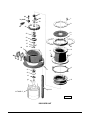
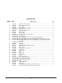
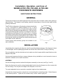
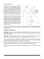
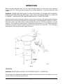
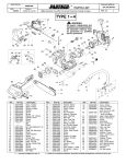
INSTRUCTION MANUAL
… with Replacement Parts
MODELS
FD3-150, FD3-200 & FD3-300
FOOD WASTE DISPOSERS
ML-110301
ML-110305
ML-110309
A product of HOBART CORPORATION 701 RIDGE AVENUE
FORM 19307 Rev. B (9-97)
FD3-150
FD3-200
FD3-300
TROY, OHIO 45374-0001
37
36
38
1
33-34-35
39
2
31
32
3
30
4
29
28
27
26
5
25
6
8
7
24
23 22
9
21
11
20
19
18
10
12-13
14 THUR 17
PL-22349-1
DISPOSER UNIT
–2–
DISPOSER UNIT
ILLUS.
PART
PL-22349-1 NO.
1
2
3
4
5
6
7
8
9
10
11
12
13
14
15
16
17
SC-118-16
00-203185
00-202105
00-201492
00-203191
00-200942-00001
SC-041-12
FP-066-02
00-289002
00-201228
SC-088-36
00-288380-00001
00-289026-00001
00-475137-00001
00-475137-00002
00-475137-00007
00-475137-00008
18
19
20
21
22
23
24
25
26
27
28
29
30
31
32
33
34
35
36
37
38
39
00-203619-00001
00-288999
RR-006-02
BB-017-39
00-201420
00-204852
SC-036-40
00-473199
00-289012
00-202724
00-289012
00-203193
00-114144
00-201210
00-292120
00-201223-00003
00-201223-00001
00-201223-00004
00-202556-00002
NS-031-43
00-201234
00-272004
00-289037
00-294904
NAME OF PART
AMT.
Cap Screw 1⁄4-20 x 1 3⁄8 Hex Hd. .................................................................................................. 10
Ring - Top Cone Clamp (Half) ...................................................................................................... 2
Guard - Splash ............................................................................................................................. 1
Ring - Isolating ............................................................................................................................. 1
Ring - Bottom Cone Clamp (Half) ................................................................................................. 2
Housing - Upper ........................................................................................................................... 1
Cap Screw 5⁄16-18 x 7⁄8 Hex Hd. ..................................................................................................... 4
Plug 1⁄2 Sq. Hd. Pipe ..................................................................................................................... 1
Gasket - Waste ............................................................................................................................. 1
Ring - Shredder ............................................................................................................................ 1
Set Screw 5⁄16-18 x 1⁄2 Hex Hdls. Cup Pt. ....................................................................................... 3
Leg & Bullet Foot .......................................................................................................................... 3
Leg & Flanged Foot ...................................................................................................................... 3
Motor (120/208-240 V., 60 Hz., 1 Ph.)(ML-110301 & ML-110305) .............................................. 1
Motor (110-120/220-240 V., 50 Hz., 1 Ph.)(ML-110301 & ML-110305) ....................................... 1
Motor (208-240/480 V.,60 Hz.,3 Ph. & 220-240/380-415 V.,50 Hz., 3 Ph.)(ML-110301) ............. 1
Motor (208-240/480 V.,60 Hz.,3 Ph. & 220-240/380-415 V.,50 Hz., 3 Ph.)(ML-110305 &
ML-110309) .................................................................................................................................. 1
Key - Shaft .................................................................................................................................... 2
Seal - Oil ....................................................................................................................................... 1
Retaining Ring .............................................................................................................................. 1
Ball Bearing - MRC 205 SZZ-01-ST-A-92-C ................................................................................ 1
Gasket - Spout ............................................................................................................................. 1
Flange - Outlet .............................................................................................................................. 1
Cap Screw 5⁄16-18 x 1 1⁄4 Hex Hd. .................................................................................................. 2
Lower Housing ............................................................................................................................. 1
Spacer .......................................................................................................................................... 1
Slinger - Water ............................................................................................................................. 1
Spacer .......................................................................................................................................... 1
Support - Seal .............................................................................................................................. 1
Water Seal Assy. .......................................................................................................................... 1
Flywheel ....................................................................................................................................... 1
Flow Control (8 G.P.M.) ................................................................................................................ 1
Cutter - Flywheel (ML-110301) ..................................................................................................... 2
Cutter - Flywheel (ML-110305) ..................................................................................................... 2
Cutter - Flywheel (ML-110309) ..................................................................................................... 2
Screw ........................................................................................................................................... 2
Stop Nut 3⁄4-16 “Elastic” ................................................................................................................ 1
Cutter - Hi-Bulk ............................................................................................................................. 1
Seal - Shaft ................................................................................................................................... 1
Seal & Bearing Kit (Incls. items 19, 20, 26 thru 30 & 39) ............................................................. 1
Shim, Spring (Used Under Brg. Bracket End Motor Bearing) ...................................................... 1
–3–
Installation, Operation, and Care of
MODELS FD3-150, FD3-200, & FD3-300
FOOD WASTE DISPOSERS
SAVE THESE INSTRUCTIONS
GENERAL
The disposer features removable hardened steel components and reversible rotation with grinding in
both directions. The disposer is self-feeding, making it unnecessary to force the food waste into the
grinding mechanism.
The FD3 Series disposers utilize hardened steel cutter blocks
(1, Fig. 1) mounted to a rotating flywheel (4, Fig. 1) and a
stationary shredder ring (2 Fig. 1) to grind food waste to a small
particle size for discharge through waste lines. With the motor
running and flushing water turned on, food waste is reduced to
grinding size by the rotating "hi-bulk" cutter (3, Fig. 1). Grinding
occurs as the food waste is forced against the shredder ring by
the cutter blocks and the centrifugal force due to rotation. The
flushing water aids the grinding action and discharges ground
food waste into the waste line.
Control groups and accessory groups are available to suit
each installation.
Fig. 1
INSTALLATION
Immediately after unpacking the disposer, check for possible shipping damage. If the disposer is found
to be damaged, save the packaging material and contact the carrier within 15 days of delivery.
Prior to installation, test the electrical service to make sure that it agrees with the specifications on the
disposer data plate.
Use legs and temporary blocking to support disposer during installation to avoid excessive stress at
welded or soldered cone to table connection.
ASSEMBLY
Use the following procedure to attach the disposer assembly to the cone (see Figs. 2 and 5).
Raise the disposer into position using the adjustable feet to bring the disposer into firm contact with
the cone flange. Do not place the weight of the disposer on the cone.
Turn each adjustable foot as required to complete height and level adjustments.
Assemble the clamp ring halves using the ten screws and tighten screws finger tight. Rotate disposer
to the desired position. Tighten the ten screws evenly to form a water tight joint.
–4–
For an accessory group D installation, use the mounting flange (1, Fig. 3) included with accessory
group D. See Fig. 3 and the accessory group data sheet.
Fig. 2
Fig. 3
WARNING: HAZARDOUS MOVING PARTS — DO NOT
OPERATE DISPOSER UNTIL PROPERLY INSTALLED
TO CONE.
Use one of the following: Part No. 204006 or 204007
(15 inch diameter cone) or Part No. 204003 or 204004
(18 inch diameter cone). For custom-built installations
— minimum thickness of stainless steel cone shall be
.035 inches and minimum height of cone (vertical
distance from work surface to disposer sink flange)
shall be 6 inches (Fig. 4).
Countertop
Work Surface
6" Minimum
Custom Built,
Locally Supplied
Cone
Disposer
PLUMBING
PL-52467
WARNING: PLUMBING CONNECTIONS MUST
COMPLY WITH APPLICABLE SANITARY, SAFETY
AND PLUMBING CODES.
Fig. 4
Drain
The disposer is furnished with a waste discharge outlet flange (7, Fig. 5) threaded with a standard 2"
IPS tapered thread. Install waste lines with the shortest possible run and best fall. If possible, use a
fall of 1/4" per foot. The waste exit must be lower than the waste outlet (see Fig. 2). The waste lines
must be thoroughly cleaned. Ream burrs from cut pipe ends and use fittings which will permit
unrestricted flow. Drum traps and grease traps must NOT be used.
–5–
Water Connections
Connect disposer (1, Fig. 5) from a 3/4" IPS cold
water supply line. Install the eight gallon per
minute flow control supplied with the disposer
(2, Fig. 5). If the water line pressure exceeds
60 psig, a pressure reducing valve (6, Fig. 5)
(not supplied) should be installed. The minimum
flow pressure for the disposer to function
properly is 16 psig. Install a shut-off valve (not
supplied) for proper servicing of the disposer.
All control groups are supplied with a solenoid
valve (4, Fig. 5 or 3, Fig. 6) which must be
installed in the water supply line as shown.
Control Group 3 is furnished with a pressure
switch (5, Fig. 5 or 4, Fig.6) which must be
installed between the solenoid valve and
pressure reducing valve. If there is no pressure
reducing valve in the water supply line, install
the pressure switch between the solenoid and
the shut-off valve.
Fig. 5
Install a vacuum breaker (3, Fig. 5) according to the local plumbing codes. If local plumbing codes
prohibit the use of a vacuum breaker, install an air gap water inlet (2, Fig. 6) (not supplied) observing
the local codes.
ELECTRICAL CONNECTIONS
WARNING: ELECTRICAL AND GROUNDING CONNECTIONS MUST COMPLY WITH THE
APPLICABLE PORTIONS OF THE NATIONAL ELECTRICAL CODE AND/OR OTHER LOCAL
ELECTRICAL CODES.
WARNING: DISCONNECT ELECTRICAL POWER SUPPLY AND PLACE A TAG AT THE
DISCONNECT SWITCH INDICATING THAT YOU ARE WORKING ON THE CIRCUIT.
This unit must be connected to a dedicated, acceptable motor control switch with a marked OFF
position to disconnect the appliance from all ungrounded supply conductors. The switch must be
mounted within sight of the disposer or sink opening for the disposer.
Knockouts are provided in the motor junction box for making electrical connections to the unit. Flexible
conduit should be used to permit moving the unit for periodic servicing and maintenance.
Select and follow wiring diagram, furnished with machine, applicable to your disposer and electrical
service.
–6–
OPERATION
Before operating disposer make sure it is clear of foreign objects such as metal or wire clippings,
screws, nails, etc., which may have dropped into it during installation. Check the flywheel for free
rotation.
WARNING: NEVER USE YOUR HAND TO CHECK ROTATION OF FLYWHEEL OR TO REMOVE
FOREIGN MATTER FROM THE DISPOSER. USE A STICK OR SIMILAR OBJECT TO TURN THE
FLYWHEEL. FOREIGN MATTER CAN BE REMOVED WITH TONGS OR PLIERS.
Start the disposer before feeding food waste. Be sure water is flowing. With typical optional controls,
water flow and unit starting are simultaneous and automatic. Feed food waste into disposer. DO NOT
feed china, metal, rags, clam shells, or similar material into the unit. DO NOT put grease or oil in the
disposer. Oil or grease can clog the drain. Always allow the disposer to run for a short period after
grinding is complete to assure proper flushing of the disposer and waste line. This flushing is
automatically controlled with certain optional controls.
Fig. 6
CONTROLS
WARNING: NEVER REACH INSIDE THIS DISPOSER WHILE IT IS OPERATING.
The operation of the disposer and additional available controls will depend on the selection of control
devices. Refer to control group data sheet.
–7–
CLEANING
The food waste disposer should be kept in a clean and sanitary condition. Allow the disposer to run
a few minutes after disposing of all food waste to completely flush out the interior. If food waste is
allowed to accumulate due to improper clean-up, it will give off offensive odors. If this happens,
cleaning can be accomplished by using a stiff brush with a strong soap and hot water solution. Light
cleaning can be accomplished by grinding ice and a lemon through the disposer.
CAUTION: Do not use chemical solvents or other drain cleaning compounds through the disposer.
MAINTENANCE
LUBRICATION
No lubrication is required for the food waste disposer. The disposer has grease packed sealed
bearings requiring no service.
CUTTER BLOCKS
The cutter blocks (1, Fig. 1) may be rotated by a qualified Hobart Service Technician if the cutting edges
become worn.
OVERLOAD PROTECTION
The disposer motor is protected by a thermal, resettable overload protector and will trip if the motor is
overloaded. To reset, allow approximately five minutes for cooling, then press the manual reset button
located on the motor shell opposite the motor junction box. An arrow on the motor shell indicates
location of the button. Restart the disposer using normal operating procedure. If overload protector
continues to trip, contact your local Hobart Service Office.
WATER SEAL VENT
A small weep hole (1, Fig. 6) in the side of the lower housing vents the dry side of the water seal. Water
leaking from this weep hole is an indication of water seal leakage. If leaking, the water seal should be
replaced. DO NOT plug or put grease in the weep hole.
FORM 19307 Rev. B (9-97)
–8–
PRINTED IN U.S.A.