1
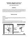
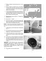
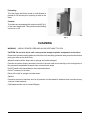
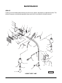
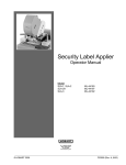
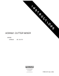
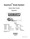
INCLUDES
REPLACEMENT
PARTS
HOBART HOBHL2 Heat Lamp
ML-136134
701 S. RIDGE AVENUE
TROY, OHIO 45374-0001
937 332-3000
www.hobartcorp.com
F-35216 (Dec. 2006)
Installation, Operation and Care of
the Hobart HOBHL2 Heat Lamp
SAVE THESE INSTRUCTIONS
GENERAL
The HOBHL2 Heat Lamp is used in conjunction with a 2912B Slicer to maintain cooked roast beef to an
internal temperature above 140°F for up to 30 minutes while slicing. The Heat Lamp is designed to hold
this temperature with roasts placed on the slicer carriage tray at a minimum temperature of 150°F for up
to 30 minutes. Additional heating lamps placed on the slicer platter and the weighing scale will prevent
additional temperature loss beyond the 20°F drop from sliced product temperature.
INSTALLATION
UNPACKING
Immediately after unpacking the Heat Lamp, check for possible shipping damage. If the Heat Lamp is
found to be damaged after unpacking, save the packaging material and contact the carrier within 15 days
of delivery to file a claim.
ASSEMBLY
The tools needed for this installation are an electric drill, a center punch and a 9/32" drill bit.
CAUTION: To reduce the risk of fire, the Heat Lamp is to be installed in non-combustible surroundings
only, with minimum clearances to combustible walls, ceilings, countertops and other combustible
materials as noted in the diagram below.
COMBUSTIBLE
CEILING
18" MIN.
12" MIN.
COMBUSTIBLE
WALLS
18" MIN.
CLEARANCE
(ALL SIDES)
18" MIN.
12" MIN.
TOP VIEW
40" MIN.
OVERHEAD CLEARANCE
12" MIN.
12" MIN.
18" MIN.
COUNTERTOPS WITHIN
FRONT VIEW
12 IN. (ALL SIDES) MUST
BE METAL OR OTHER
NON-COMBUSTIBLE MATERIAL
PL- 58302
© HOBART, 2006
–2–
1. Place skid plate on table where slicer is to be
located.
2. Make sure there is sufficient room on the table
to support the front feet of the slicer (the feet
on the index knob end of slicer) before drilling
holes for the skid plate.
3. Check beneath the tabletop to be sure there are
no hazards before drilling holes for mounting the
heat lamp. Make sure there is sufficient room
for the reinforcement base plate.
4. Mark and center punch the five 9/32" holes to be
drilled (Fig. 1).
Fig. 1
5. Drill the five 9/32" holes.
6. Line up four holes in mounting base plate with
holes in skid plate, table and reinforcement base
plate. Attach with hardware provided.
NOTE: Reinforcement base plate, lockwashers and
nuts are to be installed underneath tabletop, not on
top.
7. Install screw to secure right side of skid plate
(Fig. 1).
8. Insert heat lamp assembly onto Mounting Base
Plate (Fig. 2). Secure with thumbscrew.
9. Install four short feet on slicer and put slicer
in position with rear feet sitting in holes in skid
plate.
Fig. 2
10. Check to be sure the two 250 watt infrared bulbs
are tight in the socket. Remove one Cushion
Spring and hand tighten the bulb to be sure it is
secure. Reinstall the Cushion Spring as shown
in Fig. 3.
WARNING: ELECTRICAL AND GROUNDING
CONNECTIONS MUST COMPLY WITH THE
APPLICABLE PORTIONS OF THE NATIONAL
ELECTRICAL CODE AND/OR OTHER LOCAL
ELECTRICAL CODES.
11. Plug power cord into nearest outlet.
Fig. 3
–3–
OPERATION
WARNING: THE HEAT LAMP AND ITS PARTS ARE HOT AND CAN CAUSE BURNS. USE CARE
WHEN OPERATING, CLEANING AND SERVICING.
Set-Up
1. Place Optional Portable Platter on the slicer (Fig. 4).
2. The Main Heat Source is fixed in position over the slicer Carriage Tray (Fig. 4). No adjustment is
necessary.
3. Adjust the Front Heat Lamp Gooseneck (Fig. 4) at approximately a 45 degree angle to "shine" on
the optional portable platter. Allow enough clearance to be able to reach into this area and remove
the sliced beef without contacting the Heat Lamp housing.
4. Adjust the Rear Heat Lamp Gooseneck (Fig. 4) at approximately a 45 degree angle to "shine" on
the Weighing Scale Platter, again allowing enough room to work without contacting the Heat Lamp
housing.
Fig. 4
–4–
Preheating
The Heat Lamp should be turned on and allowed to
preheat for 30 minutes prior to placing a roast on the
slicer.
Controls
The Heat Lamp is equipped with a rocker switch (Fig. 5)
on the main support post. This switch turns the heating
sources on or off.
Fig. 5
CLEANING
WARNING:
UNPLUG POWER CORD AND ALLOW HEAT LAMP TO COOL.
CAUTION: Do not raise slicer until cool to prevent damage to plastic components on the slicer.
Remove the optional portable platter and move the front heat lamp gooseneck away from the slicer before
raising the slicer up on the lift lever.
Wash all surfaces with a damp cloth or sponge and a mild detergent.
Exercise care when cleaning around the louvers in the main heat source housing or the cooling holes in
the gooseneck lampshades so water does not enter those areas.
Do NOT wash inside lampshades or the bulbs and sockets.
Do NOT immerse unit in water.
Rinse with a cloth or sponge and clean water.
Sanitize.
Excessive amounts of sanitizer and use of products not formulated for stainless steel or aluminum may
void your Hobart warranty.
Chlorinated sanitizer not to exceed 200 ppm.
–5–
MAINTENANCE
SERVICE
Contact your local Hobart authorized service office for any repairs, adjustments or replacement parts. The
Infrared Lamps are considered expendable items and are not covered by the Hobart warranty.
6
5
4
7
8
9
3
11
10
2
1
12
48
46
45
43
14
13
47
15-16
44
17
42
39
41
38
18
40
19
36-37
20
35
21
34
33
31-32
25
30
24
23
22
29
27
26
PL-58198
28
HOBART HEAT LAMP
–6–
HOBART HEAT LAMP
ILLUS.
PL-58198
1
2
3
4
5
6
7
8
9
10
11
12
13
14
15
16
17
18
19
20
21
22
23
24
25
26
27
28
29
30
31
32
33
34
35
36
37
38
39
40
41
42
43
44
45
46
47
48
PART NO.
00-914161
00-914137
00-914136
00-914159
WL-006-06
SC-125-54
00-914134
00-438131-00003
00-914174
WL-006-06
SC-125-54
NS-011-23
00-914180
00-914190-00001
00-914167
00-914212
00-914166
00-914170-00002
00-914200
00-914542
00-914205-00002
SC-021-14
WL-006-01
SC-127-28
WL-006-06
00-914173
00-914187
00-914200
00-914170-00001
00-914166
00-914167
00-914212
00-117542-00021
FE-017-41
00-914204-00003
00-438131-00183
00-438131-00184
00-914182
00-914190-00002
00-914154
SC-129-61
00-914140
SC-127-28
WL-006-06
NS-011-12
WL-006-01
SC-021-16
00-914169
00-873255
00-914194
00-914160
00-914183
00-914540
FE-026-54
NAME OF PART
AMT.
Emitter – Full Trough (FTE) (With Spring Clip) .......................................................................... 1
Deflector – Emitter ..................................................................................................................... 1
Cover – Front Housing............................................................................................................... 1
Rivet – Nut ................................................................................................................................ 10
Lockwasher #10 Helical ............................................................................................................. 3
Mach. Screw 10-32 x 1/2 Phil. Rd. Hd. (SST) ............................................................................. 3
Housing – Heat Lamp ................................................................................................................ 1
Label – Warning ......................................................................................................................... 1
Cover – Front Top ...................................................................................................................... 1
Lockwasher #10 Helical ............................................................................................................. 4
Mach. Screw 10-32 x 1/2 Phil. Rd. Hd. (SST) ............................................................................. 4
Nut 10-32 Hex (SST) ................................................................................................................. 1
Caplug – Square (1 In.) ............................................................................................................. 1
Arm – Flex (Short Run) .............................................................................................................. 1
Shade – Infrared Lamp .............................................................................................................. 1
Label – Max (120 V., 250 Watts) ................................................................................................ 1
Spring – Cushion ....................................................................................................................... 3
Socket Assy. (250 Watt Lamp) (Long Run) ................................................................................ 1
Lamp – Infrared (120 V., 250 Watts) .......................................................................................... 1
Switch – Rocker ......................................................................................................................... 1
Cover – Switch Box Assy. .......................................................................................................... 1
Mach. Screw 8-32 x 3/8 Slotted Rd. Hd. (SST) ........................................................................... 4
Lockwasher #8 Helical ............................................................................................................... 4
Mach. Screw 10-32 x 3/8 Hex Hd. (SST) .................................................................................... 2
Lockwasher #10 Helical ............................................................................................................. 2
Base – Mounting Assy................................................................................................................ 1
Screw – Thumb .......................................................................................................................... 1
Lamp – Infrared (120 V., 250 Watts) .......................................................................................... 1
Socket Assy. (250 Watt Lamp) (Short Run) ............................................................................... 1
Spring – Cushion ....................................................................................................................... 3
Shade – Infrared Lamp .............................................................................................................. 1
Label – Max (120 V., 250 Watts) ................................................................................................ 1
Cord & Plug .............................................................................................................................. 1
Relief – Strain ............................................................................................................................ 1
Box – Switch Assy. ..................................................................................................................... 1
Label (ON) ................................................................................................................................. 1
Label (OFF) ............................................................................................................................... 1
Support – Frame Assy................................................................................................................ 1
Arm – Flex (Long Run) .............................................................................................................. 1
Cover – Support Frame ............................................................................................................. 2
Mach. Screw 10-32 x 1/4 Phil. Truss Hd. (SST) .......................................................................... 4
Grate – Heat Lamp Housing ...................................................................................................... 1
Mach. Screw 10-32 x 3/8 Hex Hd. (SST) .................................................................................... 2
Lockwasher #10 Helical ............................................................................................................. 2
Nut 8-32 Hex (SST) ................................................................................................................... 1
Lockwasher #8 Helical ............................................................................................................... 1
Mach. Screw 8-32 x 7/8 Slotted Rd. Hd. (SST) ........................................................................... 1
Block – Terminal (Emitter) .......................................................................................................... 1
Kit – Tall Foot & Skid Plate......................................................................................................... 1
Reinforcement – Base Plate ...................................................................................................... 1
Plate – Skid................................................................................................................................ 1
Platter – Portable ....................................................................................................................... 1
Housing – Heat Lamp Assy. (Incls. Items 1, 3 thru 7, & 42) ...................................................... 1
Connector – Wire Nut (High Temperature) ................................................................................ 2
–7–
NOTES
FORM 35216 (Dec. 2006)
–8–
PRINTED IN U.S.A.