1
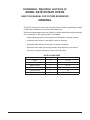
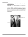
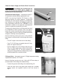
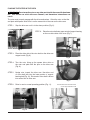
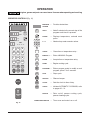
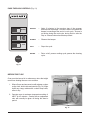
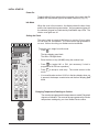
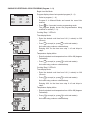
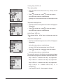
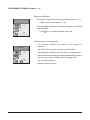
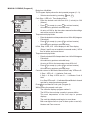
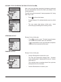
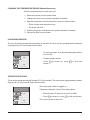
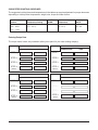
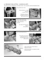
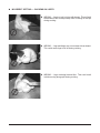
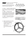
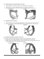
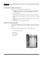
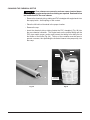
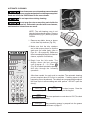
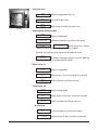
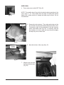
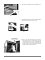
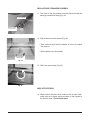
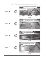
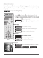
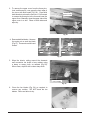
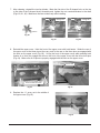
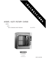
MODEL KA7E ROTARY OVENS MODEL KA7E SELF-CLEANING, Pass-Through ML-137701 701 S. RIDGE AVENUE TROY, OHIO 45374-0001 937 332-3000 www.hobartcorp.com F35521 (May, 2008) TABLE OF CONTENT GENERAL. . . . . . . . . . . . . . . . . . . . . . . . . . . . . . . . . . . . . . . . . . . . . . . . . . . . . . . . . . . . . 3 INSTALLATION. . . . . . . . . . . . . . . . . . . . . . . . . . . . . . . . . . . . . . . . . . . . . . . . . . . . . . . . . 4 Location. . . . . . . . . . . . . . . . . . . . . . . . . . . . . . . . . . . . . . . . . . . . . . . . . . . . . . . 4 Legs, Casters OR Stand ACCESSORIES . . . . . . . . . . . . . . . . . . . . . . . . . . 4 Connection Information — GENERAL . . . . . . . . . . . . . . . . . . . . . . . . . . . 4 Legend. . . . . . . . . . . . . . . . . . . . . . . . . . . . . . . . . . . . . . . . . . . . . . . . . . . . . . 4 Plumbing Connections . . . . . . . . . . . . . . . . . . . . . . . . . . . . . . . . . . . . . . . . . . 5 Chemical Cleaner Supply and Grease Drain Connections. . . . . . . . . . . . . . . 6 Electrical Connection . . . . . . . . . . . . . . . . . . . . . . . . . . . . . . . . . . . . . . . . . . . 7 PLACING THE ROTOR IN THE OVEN. . . . . . . . . . . . . . . . . . . . . . . . . . . . . . . . . 8 OPERATION. . . . . . . . . . . . . . . . . . . . . . . . . . . . . . . . . . . . . . . . . . . . . . . . . . . . . . . . . . . 9 OPERATOR CONTROLS . . . . . . . . . . . . . . . . . . . . . . . . . . . . . . . . . . . . . . . . . . . 9 PASS-THROUGH CONTROLS. . . . . . . . . . . . . . . . . . . . . . . . . . . . . . . . . . . . . . 10 Before First Use . . . . . . . . . . . . . . . . . . . . . . . . . . . . . . . . . . . . . . . . . . . . . 10 Initial Startup. . . . . . . . . . . . . . . . . . . . . . . . . . . . . . . . . . . . . . . . . . . . . . . . 11 Power On. . . . . . . . . . . . . . . . . . . . . . . . . . . . . . . . . . . . . . . . . . . . . . . . 11 Idle Mode. . . . . . . . . . . . . . . . . . . . . . . . . . . . . . . . . . . . . . . . . . . . . . . . 11 Setting the Clock. . . . . . . . . . . . . . . . . . . . . . . . . . . . . . . . . . . . . . . . . . 11 Changing Temperature Readings to Celsius. . . . . . . . . . . . . . . . . . . . . 11 Saving or Verifying a Cook Program (Program 1 – 9). . . . . . . . . 12 Programmed Cooking (Program 1 – 9). . . . . . . . . . . . . . . . . . . . . . . . 14 Manual Cooking (Program 0). . . . . . . . . . . . . . . . . . . . . . . . . . . . . . . . . 15 Holding Cycle (Silencing the 'End of Cycle' Alarm). . . . . . . . 16 Stopping a Cycle. . . . . . . . . . . . . . . . . . . . . . . . . . . . . . . . . . . . . . . . . . 16 Pausing a Cycle. . . . . . . . . . . . . . . . . . . . . . . . . . . . . . . . . . . . . . . . . . . 16 Adding Cook Time. . . . . . . . . . . . . . . . . . . . . . . . . . . . . . . . . . . . . . . . . . 17 Snoozing a Cycle (Silencing the 'End of Cycle' Alarm). . . . . 17 Cleaning the Temperature Probe (Optional Accessory). . . . . . . . 18 99 Program Feature. . . . . . . . . . . . . . . . . . . . . . . . . . . . . . . . . . . . . . . 18 Operator ID Feature. . . . . . . . . . . . . . . . . . . . . . . . . . . . . . . . . . . . . . 18 Suggested Roasting Guidelines. . . . . . . . . . . . . . . . . . . . . . . . . . . 19 Entering Recipe Data . . . . . . . . . . . . . . . . . . . . . . . . . . . . . . . . . . . . . . 19 Preparing, Tying & Spitting — Chickens on V-Spits. . . . . . 20 Spitting / Loading . . . . . . . . . . . . . . . . . . . . . . . . . . . . . . . . . . . . . . 22 Loading . . . . . . . . . . . . . . . . . . . . . . . . . . . . . . . . . . . . . . . . . . . . . . . 23 Unloading Accessories From THE Oven. . . . . . . . . . . . . . . . . . . . 24 Emptying the Grease CONTAINER. . . . . . . . . . . . . . . . . . . . . . . . . . . 24 Changing the Chemical Bottle. . . . . . . . . . . . . . . . . . . . . . . . . . . . 25 AUTOMATIC CLEANING . . . . . . . . . . . . . . . . . . . . . . . . . . . . . . . . . . . . . . . . . . 26 Wipe DOWN . . . . . . . . . . . . . . . . . . . . . . . . . . . . . . . . . . . . . . . . . . . . . . . . 28 REPLACE DRIP STRAINERS PROPERLY. . . . . . . . . . . . . . . . . . . . . . . . . 30 WIPE OFF EXTERIOR. . . . . . . . . . . . . . . . . . . . . . . . . . . . . . . . . . . . . . . . . 30 DELIMING WITH VINEGAR . . . . . . . . . . . . . . . . . . . . . . . . . . . . . . . . . . . . . . . . 32 MAINTENANCE. . . . . . . . . . . . . . . . . . . . . . . . . . . . . . . . . . . . . . . . . . . . . . . . . . . . . . . 33 Pump Tube Maintenance. . . . . . . . . . . . . . . . . . . . . . . . . . . . . . . . . . . . . . . 33 YEARLY CLEANING . . . . . . . . . . . . . . . . . . . . . . . . . . . . . . . . . . . . . . . . . . . . . . 33 TROUBLESHOOTING. . . . . . . . . . . . . . . . . . . . . . . . . . . . . . . . . . . . . . . . . . . . . . . . . . 36 Service. . . . . . . . . . . . . . . . . . . . . . . . . . . . . . . . . . . . . . . . . . . . . . . . . . . . . . . 36 © Hobart, 2008 –2– Installation, Operation and Care of MODEL KA7E ROTARY OVENS SAVE THIS MANUAL FOR FUTURE REFERENCE GENERAL The KA7E 'seven-spit' rotary oven provides evenly cooked, appealingly roasted product with combination convection and radiant heat. A full view, tempered glass door is provided for loading, and an identical pass-through door is provided on the opposite side for unloading. •Quartz lighting promotes visual appeal and stimulates customer interest. •A stainless steel interior is provided for ease of cleaning. •A pumped drain delivers excess fat to a grease receptacle. •Automatic self-cleaning thoroughly washes and cleans the oven interior. •Use only one type of accessory in the oven at any time. Type of Spit KA7E ACCESSORIES Qty Whole Chicken Capacity V-Spit 7 21 - 28 Thermo-Wave Spit 7 21 - 28 Meat Fork Spit 7 28 - 35 5-Position Rack 7 35 4-Position Rack 7 28 Baskets 7 Hold Chicken Parts –3– INSTALLATION Immediately after unpacking the oven, check for possible shipping damage. If the oven is found to be damaged, save the packaging material and contact the carrier within 15 days of delivery. Prior to installation, test the electrical service to make sure that it agrees with the specifications on the machine data plate located at the lower outside corner of the oven. LOCATION The oven must be installed on a level surface within 5 feet of both an open drain and a hot water supply. The installation location must allow adequate clearances for servicing and for proper operation. Suitable space is needed for the grease container and the chemical cleaner supply bottle and for access at the doors. For stacked and countertop configurations, the minimum clearance on the right side for plumbing and electrical connections is 3". For out-of-sight, drop-through utility connection into the stand accessory, 0" clearance is required on all sides. Wood laminates, veneers, etc. are unsuitable materials for use in areas exposed to selfcleaning oven, steam and detergents. The rotary oven must not be installed in high-moisture environments such as meat rooms or where high pressure cleaning is used. LEGS, CASTERS OR STAND Accessories A set of four 4" tall legs is available as an accessory. Casters are included with the stacking kit accessory. An oven stand accessory is available; the oven is mounted on top of the stand. Tethering is required for units equipped with casters, either on a stand or stacked. Refer to the Stand or Stacking Kit Instructions for additional installation information. CONNECTION INFORMATION — GENERAL Machine comes standard with utility connections on the right side (Figs. 1 & 2). E1 For out-of-sight, drop-through utility connection into the stand accessory, contact Hobart Service. A drop-through utilities relocation kit is included with the stand accessory. P4 Legend (Fig. 1) E1 Electrical, page 7. P3 P1 P2 P1 Water Drain, page 5. P2 Chemical Supply, page 6. P3 Grease Drain, page 6. P4 Hot Water Supply, page 5. Fig. 1 –4– Plumbing Connections Plumbing connections must comply with applicable sanitary, safety and plumbing codes. P1 Water Drain — 1" NPT female piped to an open drain. No solid connection. Output is 140°F maximum at 5 gpm. P4 Hot Water Supply — 3/4" male hose bib fitting. 0.5 gpm, 25 – 50 psi. For proper operation, use only HOT water, 120°F – 140°F. For installations at the end of a long hot water line, a second pre-rinse may be required to prime the line. Contact Hobart service to make any needed parameter changes to Cleaning cycle programming. The sensors on the machine need to see a small amount of minerals in the water in order to work properly. But, excessive minerals may cause lime scale build-up. Recommended water hardness, 4 – 6 grains. Minimum conductivity required, 30 micromhos/cm. P3 GREASE DRAIN E1 ELECTRICAL P4 HOT WATER SUPPLY P2 CHEMICAL SUPPLY P1 WATER DRAIN Fig. 2 –5– Chemical Cleaner Supply and Grease Drain Connections Oven cleaners are corrosive and can cause chemical burns. Rubber gloves, goggles and protective clothing are required. Read and follow the instructions for the oven cleaner. PIPE P2 Chemical Cleaner Supply — Hose barb to accept 1/4" ID chemically resistant tubing, supplied with oven. NOTE: Use only Kay Chemical CIP Cleaner or other approved cleaners for proper operation. Unapproved chemicals can cause excess foaming, poor dispensing, poor washing, poor draining and damage to seals and other components inside the oven. Do not use any chemicals in addition to the approved, self-dispensed cleaner as hazardous interactions can result. The amount of chemical that is self-dispensed may need to be adjusted for various reasons, such as for light or heavy soil or when using alternative approved cleaners. Contact Hobart service to make any needed parameter changes to cleaning cycle programming. TUBING Fig. 3 TUBING PIPE cAP REmOVED Hose is 6 feet long, can be cut to suit. A #4 or #6 SST hose clamp is recommended for the tubing at the barbed fitting. • Cut a 45° angle on the bottom end of the tubing. • Cut a 3/4" I.D. PVC pipe, not supplied, about 18" long, with a 45° angle at each end. • Put the angled end of the tubing inside the pipe (Fig. 3) so both angled ends extend to the bottom of the container (Fig. 4). The pipe prevents the tubing from curling inside the container and prevents suctioning against the container bottom. cHEmIcAL cONTAINER Fig. 4 P3 Grease Drain — Hose barb to accept 1/4" ID high-temperature tubing supplied with machine, 212°F rated. Hose is 6 feet long, can be cut to suit. A #4 or #6 SST hose clamp is recommended for the tubing at the barbed fitting. • Connect the grease drain tubing to the barbed fitting, P3. • Insert the other end of the grease drain tubing into a suitable grease vessel, not supplied, similar to the one shown in Fig. 5. Fig. 5 –6– Electrical Connection Electrical and grounding connections must comply with the applicable portions of the National Electrical Code, ANSI / NFPA 70, latest edition, and / or other local electrical codes. Disconnect the electrical power supply to the machine and follow lockout / tagout procedures. The electrical connection is E1 (Fig. 1). Make sure that the electrical power supply agrees with the specifications on the oven data plate. Refer to the wiring diagram located inside the side panel. Connect the power supply to the terminal block as shown on the wiring diagram. Inspect and check all wiring and terminal connections for tightness and proper routing away from any moving parts or pinch points. Carefully replace side panels. E1 – Electrical data 60 HZ VOLTAGE PHASE WATTAGE 240 1 9,300 208 1 208 3 240 3 KA7E 9,300 AMPERAGE 42.8 37.7 9,300 24.7 9,300 21.8 Field wire electrical connection is 11/4" and/or 11/2" knockout (strain relief not supplied). stacked units must be wired independently. SINGLe Phase Connection — 208V or 240V 11 21 TB1 31 12 7 1 2 3 4 5 6 7 8 22 23 13 33 9 10 11 12 1 2 3 L1 L2 L3 –7– (3W) Three Phase Connection — 208V or 240V 11 21 31 12 22 5 6 7 TB1 1 2 3 4 23 13 33 8 9 10 11 12 1 2 3 L1 L2 L3 PLACING THE ROTOR IN THE OVEN Do not wrap the rotor or any other parts inside the oven with aluminum foil. Soft metals can react with oven cleaners, and hazardous interactions can result. The rotor must properly engage with the drive mechanism. Orient the rotor so that the end plate with square drive slots is on the same side of the oven as the drive arm. STEP 1: Stop the drive arm so it is in the down position (Fig. 6). Fig. 6 STEP 2: Place the rotor shaft onto upper notch of support bearing on the non-drive side of the oven (Fig. 7). Fig. 7 STEP 3: Place the drive side of the rotor shaft on the drive arm support notch (Fig. 8). Fig. 8 STEP 4: Turn the rotor, lining up the square drive slots on the rotor end plate with the pins on the drive arm (Fig. 9). STEP 5: Nudge rotor toward the drive arm. Non-drive end of rotor shaft falls into the lower portion of support bearing hub (Fig. 10). Drive end of rotor shaft is driven into center hole of drive arm. STEP 6: Rotor is now in normal operating position (Fig. 11). Fig. 10 Fig. 9 MOTOR DRIVE PINS THROUGH DRIVE SLOTS ON ROTOR END PLATE Fig. 11 –8– OPERATION Hot glass, grease and parts can cause burns. Use care when operating and servicing the oven. Operator CONTROLS (Fig. 12) TIME • • PM AM TEMPERATURE PROGRAM • F • C ADD 5 STEP • • • • 1 2 3 4 5 6 7 8 9 START ADD 5 1 2 3 1 2 3 4 CLEAR MESSAGE — CENTER MANUAL 0 ENTER P STOP CLOCK CLEAN 4 5 6 — Adds 5 minutes to the current step of the program each time it is pressed. PROBE — Displays temperature, external meat probe. 0 – 9 — Number keys enter numeric values. ADD 5 7 8 9 0 CLEAR MANUAL MANUAL 0 — ENTER ENTER — Accepts time or temperature entry. START START — Begins cooking cycle. 0 P PROGRAM STOP Enter a MANUAL Program. — Enters program mode to modify a cook program; press P for 3 seconds. — Stops cycle. SILENCE — Silences beeper. CLOCK CLOCK — Sets the clock for time of day. CLEAN CLEAN — Initiates AUTOMATIC CLEANING, refer to pages 26 – 31. ROTATE — Rotor on/off, pauses cooking cycle; pauses cleaning cycle. ON OFF Fig. 12 — Clears time or temperature entry . CLEAR STOP ROTATE Provides instructions. MAIN POWER SWITCH –9– — Turns oven and controls on or off. Pass-ThroUgh CONTROLS (Fig. 13) SNOOZE STOP SNOOZE — Adds 10 minutes to the previous step of the program and silences the beeper. Snooze is active only when the beeper is sounding at the end of a cook cycle. Snooze is not active during the cook cycle, during Hold or after the Stop or Silence buttons have been pressed. SILENCE — Silences the beeper. STOP — Stops the cycle. ROTATE — Rotor on/off, pauses cooking cycle; pauses the cleaning cycle. ROTATE Fig. 13 BEFORE FIRST USE Oven must be burned in to release any odors that might result from heating the new oven surfaces. 1. Wipe off oven and accessories with a damp or clean soapy cloth, both inside and outside (Fig. 14). Wipe clean any soapy residue with a clean damp cloth; allow to dry. DOOR JAm 2. Operate oven at maximum temperature setting of 482°F for 45 minutes. Smoke with an unpleasant odor will normally be given off during this burn-in period. Fig. 14 – 10 – Initial Startup Power On Toggle the Main Power switch on the front panel of the oven to the ON position; the red indicator light on the switch comes on (Fig. 15). Idle Mode When the oven is first turned on, the display shows the time of day and the last operated program number. Any programmed steps for the selected program are indicated by illuminated step LEDs. The interior oven lights are off. Setting the Clock The oven's clock is preset at the factory to run two 12-hour cycles for A.M. and P.M. as standard. The clock can be reprogrammed to run as a 24-hour clock by your Hobart service technician. TIME PROGRAM P0 CLOCK • AM • PM 9:2 5 TEMPERATURE To set the clock, begin from idle mode. • Press . ADD 5 • F • C • Enter the time of day (HH:MM) using the number keys. • • • • 1 2 3 4 2 3 4 5 6 7 8 9 START MANUAL • Press to toggle A.M. or P.M. (not necessary if clock is programmed for 24-hour operation). CLOCK STEP 1 CLEAR The time display goes blank. The AM or PM light blinks. 0 ENTER P STOP CLOCK CLEAN • Press mode. ENTER to accept a valid entry. The control returns to idle • If a nonvalid value such as 10:95 is in the time display when is pressed, the beeper sounds twice and the time display goes blank. ENTER Changing Temperature Readings to Celsius The oven is preprogrammed for temperatures to read in Fahrenheit degrees as standard. The oven can be reprogrammed for Celsius temperature readings by your local Hobart Service office. ON OFF Fig. 15 – 11 – SAVING OR VERIFYING A COOK PROGRAM (Program 1 – 9) Begin from Idle Mode. Example Program Step 1 Step 2 Step 3 Step 4 Temperature Time 375 1:20 425 0:05 325 0:05 200 HOLd Program display shows last operated program (0 – 9). • Select a program (1 – 9). Program 0 is Manual Mode and cannot be saved into memory. • Press P for 3 seconds to enter programming mode. The program display shows the program/number being modified or verified (1 – 9). Cooking 'Step 1' LED is lit. PROGRAMMING # 1 ENTER STEP1 TIME TIME 1:20 TEMPERATURE 0 AM PM F P1 STEP 1 2 3 4 PROGRAMMING # 1 ENTER STEP1 TEMP TIME 1:20 TEMPERATURE 375 AM PM P1 C STEP 1 2 3 4 PROGRAMMING # 1 ENTER STEP2 TIME TIME 0:05 TEMPERATURE 0 AM PM F C PROGRAM P1 STEP 1 2 3 4 PROGRAMMING # 1 ENTER STEP2 TEMP TIME 0:05 TEMPERATURE 425 PROGRAM P1 • Press ENTER to accept (or, press CLEAR to void and reenter). Entering 0:00 for the time turns step 1 off and skips to step 2. Temperature display blinks. • Enter the desired cook temperature from 180 to 482 (degrees Fahrenheit). • Press ENTER to accept (or, press CLEAR to void and reenter). An invalid entry produces a double beep. F PROGRAM • Enter the desired cook time from 0:01 (1 minute) to 6:00 (6 hours). An invalid entry produces a double beep. C PROGRAM Time display blinks. AM PM Cooking 'Step 2' LED is lit. Time display blinks. • Enter the desired cook time from 0:01 (1 minute) to 6:00 (6 hours). • Press ENTER to accept (or, press CLEAR to void and reenter). An invalid entry produces a double beep. Entering 0:00 for the time turns step 2 off and skips to step 3. Temperature display blinks. • Enter the desired cook temperature from 180 to 482 (degrees Fahrenheit). • Press ENTER to accept (or, press CLEAR to void and reenter). An invalid entry produces a double beep. F C STEP 1 2 3 4 – 12 – Cooking 'Step 3' LED is lit. Time display blinks. PROGRAMMING # 1 ENTER STEP3 TIME TIME 0:05 TEMPERATURE 0 AM PM F PROGRAM STEP 1 2 3 4 PROGRAMMING # 1 ENTER STEP3 TEMP TIME 0:05 TEMPERATURE 325 AM PM F P1 ENTER to accept (or, press CLEAR to void and reenter). Entering 0:00 for the time turns step 3 off and skips to step 4. Temperature display blinks. • Enter the desired cook temperature from 180 to 482 (degrees Fahrenheit). • Press ENTER to accept (or, press CLEAR to void and reenter). An invalid entry produces a double beep. C PROGRAM • Press An invalid entry produces a double beep. C P1 • Enter the desired cook time from 0:01 (1 minute) to 6:00 (6 hours). STEP 1 2 3 4 HOLd 'Step 4' LED is lit. Time displays HOLd. 'HOLd' time is infinite and cannot be set. Temperature display blinks. PROGRAMMING # 1 ENTER STEP4 HOLD TIME HOLd TEMPERATURE 200 AM PM F P1 An invalid entry produces a double beep. An entry of 000 for the temperature turns HOLd off. C PROGRAM • Enter the desired Hold temperature from 140 to 230 (degrees Fahrenheit). STEP 1 2 3 4 • Press ENTER to accept (or, press CLEAR to void and reenter). An invalid entry produces a double beep. The controller returns to Idle Mode, any programmed steps for the selected program are indicated by illuminated LEDs. PROGRAM # 1 SAVED TIME AM 9:30 TEMPERATURE 425 PROGRAM P1 PM F C STEP 1 2 3 4 Step 1 LED is lit – indicates cook step 1 is programmed. Step 2 LED is lit – indicates cook step 2 is programmed. Step 3 LED is lit – indicates cook step 3 is programmed. Step 4 LED is lit – indicates HOLd, step programmed. If no Step LEDs are lit – the program is cleared. – 13 – 4, is Programmed Cooking (Program 1 – 9) Begin from Idle Mode. TIME AM 9:30 TEMPERATURE 425 PM F C PROGRAM P1 STEP The Program display shows the last operated program (0 – 9). • Select a saved cook program (1 – 9). Any programmed steps for the selected program are indicated by lit step LEDs. • Press START to run a preprogrammed cook cycle. 1 2 3 4 While running a cooking program . . . • • • COOKING • • • PROGRAM 1 STEP 1 TIME AM 1:30 TEMPERATURE 375 PROGRAM P1 PM F C STEP 1 2 3 4 The controller displays the number of the program in operation. The LED for the cook step currently in process blinks. The temperature setting of the cook step in process displays. The total combined cook time (for all programmed steps) displays. The time colon blinks to indicate time is counting down. The oven light comes on. Heaters and fans come on. – 14 – Manual Cooking (Program 0) Begin from Idle Mode. The Program display shows the last operated program (0 – 9). PROGRAM MODE ENTER STEP 1 TIME TIME 1:30 TEMPERATURE 0 AM PM F STEP P0 1 2 3 4 PROGRAM MODE ENTER STEP 1 TEMP TIME 1:30 TEMPERATURE 375 PM F PROGRAM 1 2 3 4 PROGRAM MODE ENTER STEP 4 HOLD TIME HOLd 200 PM F PROGRAM STEP 1 2 3 4 AM 9:30 TEMPERATURE 425 PM F C PROGRAM P0 STEP 1 2 3 4 • • • COOKING 0 • • • PROGRAM 0 STEP 1 TIME AM 1:30 TEMPERATURE 375 PROGRAM P0 ENTER to accept (or, press CLEAR to void and reenter). An entry of 0:00 for the time clears manual mode settings and returns contol to idle mode. Temperature display blinks. • Enter the desired cook temperature from 180 to 482 (degrees Fahrenheit). • Press ENTER to accept (or, press CLEAR to void and reenter). HOLd, Step 4 LED, is lit. HOLd displays in the Time display. (Steps 2 and 3 are not available in manual mode.) HOLd time is infinite and cannot be set. Temperature display blinks. • Enter the desired HOLd temperature from 140 to 230 degrees Fahrenheit. An invalid entry produces a double beep. An entry of 000 for the temperature turns HOLd off. PROGRAM 0 SAVED TIME • Press . An invalid entry produces a double beep. AM C P0 • Enter the desired cook time from 0:01 (1 minute) to 6:00 (6 hours). ENTER An invalid entry produces a double beep. STEP TEMPERATURE MANUAL Cook Step 1 LED is lit. Time display blinks. AM C P0 • Select manual mode by pressing 0 and C PROGRAM PM F • Press ENTER to accept (or, press CLEAR to void and reenter). An invalid entry produces a double beep. Controller returns to Idle Mode, Manual Mode 'step' LEDs are lit. If Step 1 LED is lit — it indicates Cook only. If Step 1 & Step 4 LEDs are lit — it indicates Cook & Hold. If no Step LEDs are lit — it indicates Manual Mode is cleared and that no steps have been entered. Press START to run Manual Cook cycle (Program 0). While running the manual cook cycle . . . The controller displays program number 0. The LED for the cook step currently in process blinks. The cook temperature of the cook step in process displays. The cook time displays and begins to count down. Both oven lights come on (one of them cycles on and off). C STEP Heaters and Fans come on. 1 2 3 4 – 15 – HOLDING CYCLE (SILENCING THE 'END OF CYCLE' ALARM) • • • HOLDING • • • PRESS SILENCE TIME 0:00 TEMPERATURE 325 AM PM F C PROGRAM 1 STEP 1 2 3 4 • • • HOLDING • • • PROGRAM 0 STEP 4 TIME AM 11:00 TEMPERATURE 200 PM The Hold cycle will not execute if it was programmed 'off', using Hold Temp = 000. • Press • Program displays "H" to indicate that the oven is in a Hold cycle. • The oven retains heat during a Hold cycle. Avoid overcooking by unloading when cooking is done. F STEP 1 2 3 4 STOPPING A CYCLE During a Cook or Hold cycle, TIME AM 11:05 TEMPERATURE 200 PM F 1:29 PROGRAM 1 STOP If is pressed after a cook cycle has been completed, the oven will not execute the Hold cycle. STOP STEP TIME 425 Press to stop the cycle. The light, fan and heaters turn off, and the controller returns to Idle Mode. 1 2 3 4 PAUSING A CYCLE TEMPERATURE • C PROGRAM 1 to silence the beeper. C PROGRAM H After a cook cycle has been completed, the beeper sounds and the oven automatically executes the Hold cycle (Step 4 of the cooking program). During a Cook or Hold cycle, • Push the Rotate Knob to pause the cycle. AM The Time and Temperature displays blink. Controller stops counting down. Heaters and Fan turn off. Interior lamp stays on. The controller beeps a reminder alarm if the cycle has been paused for over 3 minutes. Push the Rotate Knob to restart a cycle. PM F C STEP 1 2 3 4 • – 16 – ADDING COOK TIME • Press during a cooking cycle to add 5 minutes of cook time to the current step of the program in process. Press during the end of cycle buzzer or during Hold cycle to add 5 minutes of cook time to the last step of the last operated program. Press multiple times to add as much as desired up to a maximum total cook time of 6 hours. ADD 5 TIME AM :05 TEMPERATURE 325 PM F C PROGRAM P1 TIME STEP • ADD 5 is not active in Idle Mode after STOP has been pressed. 1 2 3 4 AM :10 TEMPERATURE 325 PM F C PROGRAM P1 STEP 1 2 3 4 SNOOZing a cycle (Silencing the 'end of cycle' alarm) After a cooking cycle has been completed, the beeper sounds and the oven automatically executes the Hold cycle (step 4 of the cooking program). The Hold cycle will not execute if it was programmed to be "off" by setting the Hold temperature at 000. SNOOZE • Press SNOOZE (Fig. 16) to silence the beeper and add 10 minutes to the previous step of the cook program. Snooze is only active when the beeper is sounding at the end of a cooking cycle. It is not active during a cook cycle. It is not active in idle mode after STOP has been pressed. It is not active in Hold mode after SILENCE has been pressed. STOP ROTATE Fig. 16 – 17 – CLEANING THE TEMPERATURE PROBE (Optional Accessory) Clean the temperature probe after every use. 1. Remove the probe from the probe holder. 2. Unplug probe cord from the probe receptacle (if needed). 3. Wipe the probe with a cloth moistened in a soap and water solution. • Rinse in clean water and allow to dry. • Dry with a soft cloth. 4.Carefully plug probe cord back into the probe receptacle (if needed). 5. Place probe back in probe holder. 99 PROGRAM FEATURE The oven is preprogrammed with 9 programs as standard. The oven can be reprogrammed to enable all 99 programs by your local Hobart Service office. TIME AM 9:30 TEMPERATURE PM F C PROGRAM • Program display flashes. • Press reenter). ENTER STEP 1 • To select a program, enter the desired program number from 0 to 99. to accept (or, press CLEAR to void and 1 2 3 4 OPERATOR ID FEATURE The oven is preprogrammed with Operator ID "off" as standard. The oven can be reprogrammed to enable Operator ID "on" by your local Hobart Service office. After main power switch is toggled on. . . TIME AM 0 TEMPERATURE Id PROGRAM PM F Temperature displays "Id" and Time display blinks. • Enter Operator ID number from from 0 to 9999. • Press C STEP ENTER to accept (or, press The control returns to idle mode. 1 2 3 4 – 18 – CLEAR to void and reenter). SUGGESTED ROASTING GUIDELINES The suggested cooking times and temperatures in the table may require adjustment for proper doneness depending on initial product temperature, weight, size, shape and other factors. Product Chicken, Whole, 3.0 — 3.5 lb. (1.4 — 1.6 kg) Oven Temperature Setting 350 – 375 °F (177 – 195 °C) Cook Time HH:MM 1:10 to 1:30 Final Internal Temperature Capacity KA7E (82 – 85 °C) 21 – 35 180 – 185 °F Entering Recipe Data The recipe cards, below, are provided to allow you to pencil in your own cooking recipe(s). PROGRAM # PROGRAM # TEMPERATURE TIME TEMPERATURE TIME STEP 1 STEP 1 STEP 2 STEP 2 STEP 3 STEP 3 STEP 4 STEP 4 (HOLD) (HOLD) PROGRAM # PROGRAM # TEMPERATURE TIME TEMPERATURE TIME STEP 1 STEP 1 STEP 2 STEP 2 STEP 3 STEP 3 STEP 4 STEP 4 (HOLD) (HOLD) – 19 – PREPARING, TYING & spitting — chickens ON V-SPITS The rotary oven is not designed to roast frozen foods. Use only fresh or previously thawed product. Bring chickens from cooler. Check temperature — range should be from 37°F to 42°F. Insert approved popper, if available; it will pop out when chicken is done. Using an approved tie, wrap around legs, pulling tie along the back, criss-cross over back. Tie comes over front holding wings to side of chicken. Insert V-Spit through neck first. The flat side of spit must be parallel with breast bone. Legs and thighs on same side as breast. Neck toward drive end Pointed end Drive end Chicken legs toward pointed end – 20 – V-Spit complete with four birds ready for loading into rotisserie. Continue until all spits are completed, all birds are properly spitted. INCORRECT spitting — chickens ON V-SPITS t WRONG — Angle of spit is in line with breast. This will split the backbone and could possibly result in falling off the spit during cooking. t WRONG — Legs and thighs are not on same side as breast. This could cause legs to fall off during cooking. t WRONG — Legs are being inserted first. This could result in birds moving along spits during cooking. – 21 – Spits are sharp. Use care when loading product. spitting — chickens ON FORK SPITS Press pointed ends of spits into whole poultry so points go through the chest-wing and leg-thigh regions (Fig. 17). Load four or five chickens on each fork spit. Fig. 17 spitting — chickens ON THERMO-WAVE SPITS After tying chickens, insert thermo-wave spit through neck first. Load three or four chickens on each thermowave spit. Loading — ChickenS ON Racks Place chicken cavity over spindle, legs down, neck up and breast forward (Fig. 18). Fold and cross legs; hook leg ends under side rods of rack. Break wings at top joint; fold wings behind bird. Load four- or five-chickens per rack, depending on rack. Load seven racks. Fig. 18 Loading — Chicken pieces in Baskets Load chicken pieces in basket in any appropriate arrangement (Fig. 19). Fig. 19 LOADING ACCESSORIES ON THE ROTOR • Advance the Rotor as needed using the Rotate Knob, load accessory into position 1, skip position 2, load position 3, etc. (Fig. 20). • Chickens must clear top of oven; no parts can stick out. • Do not mix different types of accessories on the rotor at the same time. 6 Skip 5 Load 4 Skip 7 Load 1 Load 3 Load 2 Skip Fig. 20 – 22 – Loading V-Spits or Thermo-Wave Spits on the Rotor 1. Place pointed end of V-spit into outside hole on non-drive side of rotor (Fig. 21). 2.Fit notched end of V-spit into appropriate holes on drive side of rotor (Fig. 22). 3.Make sure the spit is level. If the spit is not level, you might be using the wrong holes. NON-DRIVE SIDE DRIVE SIDE Fig. 21 Fig. 22 Loading Fork Spits on the Rotor 1. Place pointed ends of fork spit into appropriate holes on the non-drive side of the rotor (Fig. 23). 2.Fit the notched end of fork spit into appropriate holes on the drive side of the rotor (Fig. 24). NON-DRIVE SIDE DRIVE SIDE Fig. 23 Fig. 24 Loading Chicken Racks or Baskets on the Rotor Chicken Racks and Chicken Baskets hang on studs on the left and right sides of the rotor. 1. Hang the left end of a Rack or Basket on a stud on the left side of the rotor (Fig. 25). 2. Hang the right end of the Rack or Basket on the corresponding stud on the right side of the rotor at the same height (Fig. 26). The accessory must be level. NON-DRIVE SIDE DRIVE SIDE Fig. 25 Fig. 26 – 23 – the oven. Hot glass, grease and parts can cause burns. Use care when operating and servicing UNLOADING ACCESSORIES FROM THE OVEN Opening the door does not stop the rotor, heaters or fan. 1. Press to stop rotation and cooking. Press Rotate Knob to allow rotor to advance to unloading position. Press Rotate Knob again to stop rotation. STOP 2. Use insulated gloves. • Carefully remove accessory from rotor. Remove chickens from accessory. • Place chickens in proper containers. Place chicken containers in warming cabinet. 3. Repeat step 1; stagger unloading by skipping past the next accessory to the following one. 4. Repeat step 2 and 3 until unloading is complete. EMPTYING THE GREASE CONTAINER The KA7E automatically pulses the grease pump on and off throughout the cooking cycle, draining the grease into a suitable container (not supplied, Fig. 27). NOTE: Empty the grease container routinely — avoid overflow spills. • Press main power switch Off. • Remove tube. • Empty container. • Replace tube. Fig. 27 – 24 – Changing the Chemical Bottle Oven cleaners are corrosive and can cause chemical burns. Rubber gloves, goggles and protective clothing are required. Read and follow the instructions for the oven cleaner. • Remove the chemical pick-up tubing and PVC standpipe with angled ends from the empty bottle. Avoid spilling or skin contact. • Place the full bottle of chemical in the proper location. • Remove the cap. • Insert the chemical pick-up tubing (inside the PVC standpipe) (Fig. 28) into the new chemical container. The angled ends on the pickup tubing and the PVC pipe enable proper suction and prevent the tubing from sitting flat on the bottom of the bottle (Fig. 29). The top of the container must be open to prevent a vacuum, thus permitting the chemical cleaner to be pumped up, into the sump. TUBING PIPE cAP REmOVED PIPE TUBING Fig. 28 cHEmIcAL cONTAINER Fig. 29 – 25 – AUTOMATIC CLEANING Oven cleaners are corrosive and can cause chemical burns. Rubber gloves, goggles and protective clothing are required. Read and follow the instructions for the oven cleaner. Do not open doors during cleaning. Do not wrap the rotor or any other parts inside the oven with aluminum foil. Soft metals can react with oven cleaners, and hazardous interactions can result. NOTE: The self-cleaning oven is not intended to be a utensil washer. Remove all accessories (Fig. 31) before you press clean. Fig. 30 1. Remove any debris, bones or pieces of skin from drip strainers (Fig. 32). 2.Make sure that the drip strainers are in their proper places so that the wash arm can rotate freely (refer to Figs. 43 – 45 on page 30). Make sure there is an adequate supply of chemical cleaner; replenish if necessary. TIME TEMPERATURE PROGRAM • AM • PM • F • C ADD 5 1 2 3 4 5 6 7 8 9 START cook program (0 - 9). Press (Fig. 33) to initiate automatic cleaning, and step through the following operations . . . STEP • • • • CLEAR 3. Begin from the Idle mode. The display shows the last operated CLEAN 1 2 3 4 MANUAL 0 ENTER P STOP CLOCK CLEAN Fig. 33 Fig. 31 Fig. 32 Allow time needed for each cycle to complete. The automatic cleaning process requires about 2.5 hours to complete. If nothing seems to be happening, do not be alarmed. Time delays are programmed throughout the clean cycle to allow soaking and other pauses. DO NOT open the door(s). • • • PRESS CLOSE THE DOOR THEN PRESS CLEAN START OR CLEAN 34 The door is open. Close the door completely. Then press the Clean key on the keypad. CLEANING PREHEATING The oven preheats or cools down to 150°F, the best temperature for cleaning. CLEANING DRAINING GREASE Any remaining grease is pumped into the grease container. Cleaning continues on page 27. – 26 – • Pre-rinse cycle. Fig. 34 • CLEANING WATER FILL • CLEANING DEGREASE # 1 The oven rinses briefly. • CLEANING WATER DRAIN Water drains from the Pre-rinse cycle. Water is being added (Fig. 34). • Washing and Soaking cycles. • • • CLEANING WATER FILL Water is being added. CLEANING ADDING DETERGENT Detergent is added to the water in the sump. CLEANING CLEANING WASHING SOAKING 34 Water sprays for 1 minute, then turns off to allow soaking for 7 minutes. Repeat. • Washing and Soaking cycles repeat for the next two hours. • CLEANING WATER DRAIN The water / detergent solution from the Washing and Soaking cycles is pumped down the drain. • Rinse cycle, #1. • CLEANING WATER FILL Water is being added. • CLEANING RINSE # 1 Water sprays in the oven, rinsing for a set time. • CLEANING WATER DRAIN Water is drained from Rinse cycle #1. •N Rinse cycle, #2. N • CLEANING WATER FILL Water is being added. N • CLEANING RINSE # 2 Water sprays in the oven, rinsing for a set time. • CLEANING WATER DRAIN Water is drained from Rinse cycle #2. • Drying cycle. • CLEANING DRYING N • CLEANING CYCLE COMPLETE The oven heats up to dry out the interior. – 27 – Cleaning cycle is done; continue on page 28. WIPE DOWN 4. Press main power switch OFF (Fig. 35). NOTE: Thoroughly wipe off any white chemical residue remaining in the oven, steps 5 – 10. If the residue does not wipe off readily with a clean damp cloth, a dilute solution of vinegar and water may be used. Do not use abrasives. Fig. 35 STRAINER UPSIDE DOWN 5. Remove the drip strainers. The underneath surface of the drip strainers may also have white chemical residue or dirt. If necessary, wipe off the underside of the drip strainers with a clean damp cloth (Fig. 36). If necessary, take the drip strainers to a sink; wash and rinse them thoroughly and wipe dry with a clean cloth. Fig. 36 SUmP BOTTOm STRAINERS REmOVED 6. Wipe the bottom of the sump (Fig. 37). DOOR JAm Fig. 37 7. Wipe the area around the face of the door jam (Fig. 38). Fig. 38 – 28 – 8. Wipe out the trough below the door opening (Fig. 39). WIPE OUT TROUGH Fig. 39 9. Separate the inner and outer doors by grasping at either the upper or the lower corner (Figs. 40, 41). GRASP AT BOTTOm GRASP AT TOP Of DOOR Fig. 40 WIPE cLEAN ALL INSIDE AND OUTSIDE GLASS DOOR SURfAcES Fig. 41 10. Wipe off the inside and outside glass surfaces of both glass doors (Fig. 42) on both the operator and customer sides of the oven. Wipe off wet glass with a clean dry cloth to avoid streaks. If white chemical residue is difficult to remove using water alone, use a dilute solution of vinegar and water. Fig. 42 – 29 – REPLACE DRIP STRAINERS PROPERLY NOTcH ON SIDE Of DRIP STRAINER 11. The notch in the drip strainer must be placed around the water pipe and block fitting (Fig. 43). WATER PIPE AND BLOck fITTING Fig. 43 12. Drip strainers must be seated (Fig. 44). • Tabs under the drip strainer handles fit slots in the wash arm support. • Both handles are in the middle. DRIP STRAINERS ARE SEATED Fig. 44 13. Wash arm spins freely (Fig. 45). Q Fig. 45 WIPE OFF EXTERIOR 14. Wipe exterior stainless steel surfaces with a moist cloth, using care not to apply excess moisture to the keypad in the controls area. Do not hose down. – 30 – Figs. 46, 47, 48 and 49 show wrong ways to assemble the drip strainers. DRIP STRAINERS ARE TURNED 90 DEGREES HANDLES SHOULD BE IN THE mIDDLE TABS ARE NOT IN SLOTS ON WASH ARm SUPPORT WRONG t Fig. 46 DRIP STRAINERS ARE NOT SEATED WASH ARm IS UNDERNEATH WRONG t Fig. 47 DRIP STRAINERS UPSIDE DOWN WRONG t Fig. 48 DRIP STRAINERS TURNED 90 DEGREES HANDLES SHOULD BE IN mIDDLE WRONG t Fig. 49 – 31 – DELIMING WITH VINEGAR Remove all accessories. The rotor can remain. Deliming with vinegar provides a short rinse to clear out any remaining soapy residue from cleaning or chemical salts. Deliming is recommended once a week, after an automatic cleaning cycle and after manually wiping out the oven interior (refer to pages 26 through 31). Do not open doors during deliming. 1. Press the TIME TEMPERATURE PROGRAM • AM • PM • F • C ADD 5 CLEAN key. Press the 0 key within 20 seconds (Fig. 50). MANUAL •If the 0 key is not pressed within 20 seconds, the oven goes into automatic cleaning discussed on pages 26 – 31. To stop automatic cleaning, press the key and repeat step 1. MANUAL STOP 2. ADD DE-LIMING AGENT displays for 20 seconds. Open the door and add 2 quarts of vinegar to the sump. Close the door. Wait. STEP • • • • Washing cycle. 1 2 3 3. CLEANING DE-LIMING CYCLE Water is added to the sump. 4 5 6 CLEANING DE-LIMING CYCLE 7 8 9 4. The delime cycle runs for 20 minutes (Fig. 51). 5. CLEANING DE-LIMING CYCLE The vinegar and water solution drains. 1 2 3 4 CLEAR START MANUAL 0 ENTER P STOP CLOCK CLEAN Fig. 50 Rinsing cycle. 6. CLEANING DE-LIMING CYCLE Water is added to the sump. 7. CLEANING DE-LIMING CYCLE Water sprays, rinsing for a set time. 8. CLEANING DE-LIMING CYCLE Water drains from the rinse cycle. Drying cycle. 9. CLEANING DRYING The oven heats, drying the interior for 10 minutes. SELECT PRESS DE-LIMING 10. 34 34 PROGRAM 0 - 9 START OR CLEAN CYCLE COMPLETE Control returns to Idle mode. Deliming is complete. Fig. 51 – 32 – PUMP TUBE MAINTENANCE MAINTENANCE Pump tubing is a wear item. Contact Hobart Service to replace tubing periodically on grease pump, chemical pump and water pump to avoid leakage. TUBING LEAkS ARE DIREcTED OUTSIDE OVEN As pump tubing wears, leaks can occur. In the event of tubing leak or break, machine is designed to direct liquids to outside of oven (Fig. 52). If this condition is observed, contact Hobart service. Fig. 52 YEARLY CLEANING Wash nozzles are located between the ceiling of the oven and the upper cover to clean the convection fan and heating chamber. However, it is recommended that you inspect and clean the oven once yearly, as needed. Clean the ceiling of the oven interior to remove potential grease build-up. Excessive grease build-up on convection fan blade(s) and / or upper cover will decrease the oven's cooking performance over time. NOTE: For ease of cleaning, replacement fan blade(s) are available from Hobart Service. 1. Open the door. Make sure that the drive arm is in the downward position (Fig. 53). Press OFF. Disconnect electrical power supply to the machine and follow lockout / tagout procedures before cleaning or servicing. Hot glass, grease and parts can cause burns. Use care when operating and servicing the oven. Fig. 53 2. Remove the rotor. Lift up on the side of the rotor opposite the drive arm. Then, lift up and out to disengage the rotor from the two drive pins on the drive arm (Fig. 54). 3. Unscrew the acorn nut in the middle of the upper cover, inside the oven chamber (Fig. 55). Use a 7/16" wrench or nut driver. ROTOR REmOVED DRIVE ARm Fig. 54 Fig. 55 – 33 – 3. To remove the upper cover from the three pins, front, and three pins, rear, grasp the front edge of the cover with both hands (Fig. 56). Press with both thumbs to release the front pins. Pull forward to escape the three pins in the rear and lower the upper cover. Manually clean the upper side of the upper cover in a sink. Rinse off both sides and wipe dry. fRONT Of UPPER cOVER Fig. 56 4. Remove both fan blades. Unscrew the center nut on each fan blade (Fig. 57). These nuts are left-hand thread. FAN FAN CENTER NUT Fig. 57 5. Wipe the interior ceiling around the elements and convection fan shafts of any residue using a damp or soapy cloth, as needed (Fig. 58). When clean, wipe off with a clean damp cloth. cEILING Of OVEN cHAmBER Fig. 58 6.Clean the fan blades (Fig. 59) as required to remove any residue. Do not bend the fan blades. Rinse and allow to dry. Fig. 59 – 34 – CENTER NUT 7. After cleaning, reinstall the two fan blades: Mate the flat side of the D-shaped hole on the fan to flat side of the D-shaped shaft. Assemble and tighten the nut counterclockwise to the shaft (Figs. 60, 61, 62). Make sure the fans rotate freely after installing. FAN CENTER NUT FAN CENTER NUT D HOLE Fig. 60 Fig. 61 Fig. 62 8. Reinstall the upper cover. Hold the front of the upper cover with both hands. Guide the rear of the upper cover to the three pins at the rear; push to the rear so the three pins are engaged with the slots on the upper cover (Fig. 63). Lift up the front of the upper cover while pressing both thumbs in so that you engage the slots on the front of the upper cover with the three front pins (Fig. 64). Make sure all six pins are properly engaged with the slots on the upper cover. fRONT PINS REAR SLOTS IN UPPER cOVER ENGAGE THREE REAR PINS Fig. 64 Fig. 63 9. Replace the 7/16" acorn nut in the middle of the upper cover (Fig. 65). Fig. 65 – 35 – TROUBLESHOOTING PROBLEM POSSIBLE RESOLUTION Control does not light up. 1.Press On-Off switch on. 2.Electric supply is interrupted; check circuit breaker. Cooking too slow. Fan blade(s) and ventilation area require routine cleaning. Water isn't spraying during wash Wash cycle is in soak mode. Display says 'Soaking'. cycle. Wash arm isn't turning. Drip strainers are not in their proper place and are interfering with wash arm motion; check drip strainers. Nothing seems to be happening Oven is cooling down or preheating to the optimum temp. for cleaning. after Clean is pressed. Oven is not clean enough after 1. Chemical bottle may be empty; replace with full bottle. cleaning cycle is complete. 2. Ensure tubing is cut at an angle and that standpipe is in place to prevent tube from curling inside chemical bottle. 3. Contact Hobart service to make any needed parameter changes to cleaning cycle programming (amount of chemical or second pre-rinse cycle, etc.). Nothing seems to be happening Time delays are programmed between steps during clean cycle. in Clean Mode. Oven uses too much chemical. 1. Typical usage is approximately 1/2 gallon per day. 2.Contact Hobart service to make any needed parameter changes to clean cycle programming (amount of chemical or second pre-rinse cycle, etc.). Grease or liquids are running Pump tubing needs to be replaced. Contact Hobart service. outside the unit. ERROR MESSAGE DOOR IS OPEN CLOSE THE DOOR POSSIBLE RESOLUTION Close the door. displays. WATER FAIL CANNOT CONTINUE CLEANING CYCLE and CHECK SUPPLY display alternately; a double beep sounds. CHECK DETERGENT CHECK DETER PUMP ATTEMPTING TO DRAIN SUMP display alternately. CLEANING CANCELLED INTERRUPTED CLEAN CYCLE displays. and DRAIN FAIL CHECK DRAIN, PUMP displays. displays. 1. Open the water supply valve. 2. Remove any kinks in the hose. 3. There may be low water pressure / volume. Call Hobart service. 1. Chemical bottle may be empty; replace with full bottle. 2. Ensure tubing is cut at an angle and that standpipe is in place to prevent tube from curling inside chemical bottle. 3. Pump tubing may need routine maintenance; contact Hobart service. The sump may be clogged. Call Hobart service. Occurs if "Stop" key is pressed during Cleaning. Please wait while oven cycles through two rinse cycles and the drying cycle. Occurs if "On-Off" switch is cycled during cleaning. Please wait while oven cycles through two rinse cycles and the drying cycle. SERVICE Contact your local Hobart office. F35521 (May, 2008) – 36 – PRINTED IN U.S.A.