1
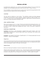
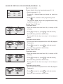
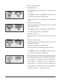
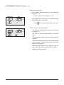
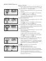
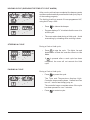
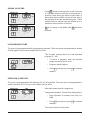
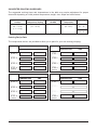
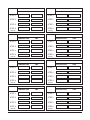
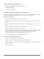
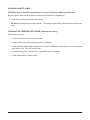
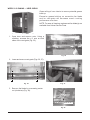
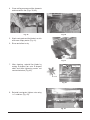
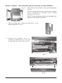
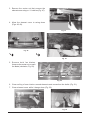
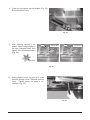
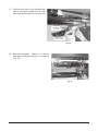
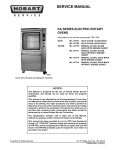
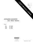
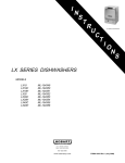
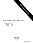
I
N
S
T
R
U
C
T
MODEL HR5E & HR7E ROTARY OVENS
HR7E ROTARY OVEN
I
O
N
S
MODEL
HR7E
STAINLESS STEEL INTERIOR, GLASS BACK
STAINLESS STEEL INTERIOR, SOLID BACK
COATED INTERIOR, GLASS BACK
COATED INTERIOR, SOLID BACK
ML-132092
ML-132095
ML-132093
ML-132094
STAINLESS STEEL INTERIOR, GLASS BACK
COATED INTERIOR, GLASS BACK
ML-132096
ML-132097
HR5E
701 S. RIDGE AVENUE
TROY, OHIO 45374-0001
937 332-3000
www.hobartcorp.com
FORM 35511 (Feb. 2006)
TABLE OF CONTENT
GENERAL . . . . . . . . . . . . . . . . . . . . . . . . . . . . . . . . . . . . . . . . . . . . . . . . . . . . . . . . . . . 3
INSTALLATION . . . . . . . . . . . . . . . . . . . . . . . . . . . . . . . . . . . . . . . . . . . . . . . . . . . . . . .
Location . . . . . . . . . . . . . . . . . . . . . . . . . . . . . . . . . . . . . . . . . . . . . . . . . . . . . . .
Legs / Casters / Stand . . . . . . . . . . . . . . . . . . . . . . . . . . . . . . . . . . . . . . . . . . . .
Electrical Connections . . . . . . . . . . . . . . . . . . . . . . . . . . . . . . . . . . . . . . . . . . . .
Single Ovens / Stacked Ovens . . . . . . . . . . . . . . . . . . . . . . . . . . . . . . . .
Electrical Data HR5E, HR7E . . . . . . . . . . . . . . . . . . . . . . . . . . . . . . . . .
Before First Use . . . . . . . . . . . . . . . . . . . . . . . . . . . . . . . . . . . . . . . . . . . . . . . . .
Placing the Rotor in the Oven (HR5E) . . . . . . . . . . . . . . . . . . . . . . . . . . . . . . .
Placing the Rotor in the Oven (HR7E) . . . . . . . . . . . . . . . . . . . . . . . . . . . . . . .
4
4
4
4
4
5
6
6
7
OPERATION . . . . . . . . . . . . . . . . . . . . . . . . . . . . . . . . . . . . . . . . . . . . . . . . . . . . . . . . . 8
CONTROLS . . . . . . . . . . . . . . . . . . . . . . . . . . . . . . . . . . . . . . . . . . . . . . . . . . . . 8
Initial Startup . . . . . . . . . . . . . . . . . . . . . . . . . . . . . . . . . . . . . . . . . . . . . . . . 9
Power On . . . . . . . . . . . . . . . . . . . . . . . . . . . . . . . . . . . . . . . . . . . . . . . 9
Idle Mode . . . . . . . . . . . . . . . . . . . . . . . . . . . . . . . . . . . . . . . . . . . . . . . 9
Setting the Clock . . . . . . . . . . . . . . . . . . . . . . . . . . . . . . . . . . . . . . . . . 9
Changing Temperature Readings to Celsius . . . . . . . . . . . . . . . . . . . 9
Saving or Verifying a Cook Program (Program 1 – 9) . . . . . . . . . . . . . 10
Programmed Cooking (Program 1 – 9) . . . . . . . . . . . . . . . . . . . . . . . . . 12
Manual Cooking (Program 0) . . . . . . . . . . . . . . . . . . . . . . . . . . . . . . . . . 13
Holding Cycle (Silencing the 'End of Cycle' Alarm . . . . . . . . . . . . . . . . 14
Stopping a Cycle . . . . . . . . . . . . . . . . . . . . . . . . . . . . . . . . . . . . . . . . . . . . 14
Pausing a Cycle . . . . . . . . . . . . . . . . . . . . . . . . . . . . . . . . . . . . . . . . . . . . 14
Adding Cook Time . . . . . . . . . . . . . . . . . . . . . . . . . . . . . . . . . . . . . . . . . . 15
99 Program Feature . . . . . . . . . . . . . . . . . . . . . . . . . . . . . . . . . . . . . . . . 15
Operator ID Feature . . . . . . . . . . . . . . . . . . . . . . . . . . . . . . . . . . . . . . . . 15
Suggested Roasting Guidelines . . . . . . . . . . . . . . . . . . . . . . . . . . . . . . . . 16
Preparing, Tying & Spitting — Chickens on V-Spits . . . . . . . . . . . . 18
Spitting / Loading — HR5E . . . . . . . . . . . . . . . . . . . . . . . . . . . . . . . . 20
Spitting / Loading — HR7E . . . . . . . . . . . . . . . . . . . . . . . . . . . . . . . . 21
Loading (HR5E) . . . . . . . . . . . . . . . . . . . . . . . . . . . . . . . . . . . . . . . . 22
Loading (HR7E) . . . . . . . . . . . . . . . . . . . . . . . . . . . . . . . . . . . . . . . . 23
Personal Protective Equipment . . . . . . . . . . . . . . . . . . . . . . . . . . . . . . . . 24
Unloading Accessories From Oven . . . . . . . . . . . . . . . . . . . . . . . . . . . . 24
Emptying the Grease Drawer . . . . . . . . . . . . . . . . . . . . . . . . . . . . . . . . . 24
CLEANING . . . . . . . . . . . . . . . . . . . . . . . . . . . . . . . . . . . . . . . . . . . . . . . . . . . . 25
Cleaning — Grease Drawer and Oven Interior / Exterior . . . . . . . . . 25
Cleaning Stainless Steel Surfaces . . . . . . . . . . . . . . . . . . . . . . . . . . . . 26
Cleaning Guidelines for Nonstick Coated Surfaces . . . . . . . . . . . . . 26
Cleaning Quartz Lamps . . . . . . . . . . . . . . . . . . . . . . . . . . . . . . . . . . . . 27
Cleaning the Temperature Probe . . . . . . . . . . . . . . . . . . . . . . . . . . . . 27
Weekly Cleaning — HR5E Ovens . . . . . . . . . . . . . . . . . . . . . . . . . . . . 28
Weekly Cleaning — HR7E Oven With Rear Glass Door . . . . . . . . . 30
Weekly Cleaning — HR7E Oven With Solid Back . . . . . . . . . . . . . . 34
MAINTENANCE . . . . . . . . . . . . . . . . . . . . . . . . . . . . . . . . . . . . . . . . . . . . . . . . . . . . . 40
TROUBLESHOOTING . . . . . . . . . . . . . . . . . . . . . . . . . . . . . . . . . . . . . . . . . . . . . . . . 40
Service . . . . . . . . . . . . . . . . . . . . . . . . . . . . . . . . . . . . . . . . . . . . . . . . . . . . . . 40
© HOBART 2006
–2–
Installation, Operation and Care of
MODEL HR5E & HR7E ROTARY OVENS
SAVE THIS MANUAL FOR FUTURE REFERENCE
GENERAL
The HR5E and HR7E Ovens are five-spit and seven-spit rotary ovens that feature a full view tempered
glass door and quartz lighting that promote visual appeal and stimulate customer interest. The solid
back model (HR7E only) is used when the oven is positioned against a wall. The glass back model
provides an identical rear glass for customer viewing; with the handle kit accessory the rear glass can
be used for pass-through operation. The HR5E and HR7E rotary ovens are available with stainless
steel or nonstick coated interior for ease of cleaning. The oven’s grease drawer has a drain valve for
elimination of excess fat; the grease drawer can be completely removed for cleaning. The oven
provides evenly cooked, appealingly roasted product with combination convection and radiant heat.
HR5E ACCESSORIES
Type of Spit
Qty
Whole Chicken Capacity
V-Spit
5
15 - 20
Meat Fork Spit
5
15 - 20
3-Position Rack
5
15
Baskets
5
NA
HR7E ACCESSORIES
Type of Spit
Qty
Whole Chicken Capacity
V-Spit
7
21 - 28
Thermo-Wave Spit
7
21 - 28
Meat Fork Spit
7
28 - 35
5-Position Rack
7
35
4-Position Rack
7
28
Baskets
7
NA
Only one type of accessory is intended to be used in the oven at a time. Do not mix accessory types.
–3–
INSTALLATION
Immediately after unpacking the oven, check for possible shipping damage. If the oven is found to be
damaged, save the packaging material and contact the carrier within 15 days of delivery.
Prior to installation, test the electrical service to assure that it agrees with the specifications on the
machine data plate located behind the left-hand hinged door.
LOCATION
The oven must be installed on a level surface. The installation location must allow adequate
clearances for servicing and for proper operation). Minimum clearance for sides and back is 0.0"
(0.0 cm). The rotary oven is not recommended for installation in high-moisture environments such as
meat rooms or where high pressure cleaning is used.
LEGS / CASTERS / STAND
Each oven is furnished on 111⁄16" (4.3 cm) legs. Casters are included with the stacking kit accessory. An
oven stand is available (HR7E only); the oven is mounted on top of the stand. Tethering is required
for units on a stand or stacked when equipped with casters. Refer to the Stand or Stacking Kit
Instructions.
ELECTRICAL CONNECTIONS
WARNING: ELECTRICAL AND GROUNDING CONNECTIONS MUST COMPLY WITH THE
APPLICABLE PORTIONS OF THE NATIONAL ELECTRICAL CODE AND / OR OTHER LOCAL
ELECTRICAL CODES.
WARNING: DISCONNECT ELECTRICAL POWER SUPPLY TO THE MACHINE AND FOLLOW
LOCKOUT / TAGOUT PROCEDURES.
Single Oven
Access the electrical connection point by removing the side panel where the controls are located. Make
sure that the electrical power supply agrees with the specifications on the oven data plate and complies
with the wiring diagram located on the inside of the side panel.
Stacked Ovens
Refer to the Stacking Kit Installation Instruction included with the stacking kit.
Attach the power supply conduit to bottom of oven. Connect the power supply to the terminal block
as shown on the wiring diagram. Inspect and check all wiring and terminal connections for tightness
and proper routing away from any moving parts or pinch points. Carefully replace side panels.
–4–
ELECTRICAL DATA
HR5E
HR5E / HR5E *
VOLTAGE
HZ
PHASE
AMPERAGE
WATTAGE
AMPERAGE
208(2W)
240(2W)
208(3W)
240(3W)
220/380(4W)
230/400(4W)
240/415(4W)
50/60
50/60
50/60
50/60
50/60
50/60
50/60
1
1
3
3
3
3
3
26.9
25.0
15.5
14.4
8.4
8.7
9.0
6000
6000
6000
6000
6000
6000
6000
53.8
50.0
31.0
28.8
16.8
17.4
18.0
Full load Amperage is measured at regulated voltage input.
* Stacked units can be wired independently or with single point connection using the stacking kit accessory.
ELECTRICAL DATA
HR7E
VOLTAGE
HZ
PHASE
208(2W)
240(2W)
208(3W)
240(3W)
220/380(4W)
230/400(4W)
240/415(4W)
50/60
50/60
50/60
50/60
50/60
50/60
50/60
1
1
3
3
3
3
3
HR7E / HR7E *
AMPERAGE WATTAGE
42.8
38.8
24.7
22.4
12.9
13.4
14.1
AMPERAGE
9300
9300
9300
9300
9300
9300
9300
NA**
NA**
49.4
44.8
25.8
26.8
28.2
Full load Amperage is measured at regulated voltage input.
* Stacked units can be wired independently or with single point connection using the stacking kit accessory.
** Single point connection is not available for stacked HR7E / HR7E single phase units.
(3W) THREE PHASE CONNECTION — 208V or 240V
SINGLE PHASE CONNECTION — 208V or 240V
TB1
1
2
3 31
7
1
2
3
5
4
4
6
7
8
5
6
61
1
2
3
4
3 31 7
4
9
9 10 11 12
1
2
3
4
5
8
9 10 11 12
TB1
1
2
3
L1
L2
L3
1
TB1
2
3
4
3 31 7
3
4
5
6
7
9
8
5
9 10 11 12
1
2
3
L1
L2
L3
TB4
2
4
1
2
2
3
L1
L2
L3
6 61
3
1
N
–5–
7
6
1
(4W) THREE PHASE CONNECTION — 220/380, 230/400, 240/415 VOLT
1
6
5
4
61
BEFORE FIRST USE
WARNING: DISCONNECT ELECTRICAL POWER SUPPLY TO THE MACHINE AND FOLLOW
LOCKOUT / TAGOUT PROCEDURES BEFORE CLEANING OR SERVICING.
Oven must be burned in to release any odors that might result from heating the new oven surfaces.
1. Clean oven and accessories, both inside and outside. Refer to CLEANING, pages 25 — 39, for
further instructions.
2. Operate oven at maximum temperature setting of 482°F (250°C) for 45 minutes. Smoke with an
unpleasant odor will normally be given off during this burn-in period.
PLACING THE ROTOR IN THE OVEN (HR5E)
The rotor must properly engage with the drive mechanism. Orient the rotor so that the end plate with
the drive pin is aligned with the slotted drive hub.
ROTOR
STEP 1: Place the drive end of the rotor shaft into
the slotted drive hub (Fig. 1).
DRIVE PIN
STEP 2: Place the rotor shaft on the support
bearing on the non-drive side of the oven
(Fig. 2).
SLOTTED DRIVE HUB
DRIVE SIDE
Fig. 1
ROTOR SHAFT
SUPPORT BEARING
NON-DRIVE SIDE
Fig. 2
–6–
PLACING THE ROTOR IN THE OVEN (HR7E)
The rotor must properly engage with the drive mechanism. Orient the rotor so that
the end plate with square drive slots is on the same side of the oven as the drive arm.
STEP 1: Stop the drive arm so it is in the down position (Fig. 3).
Fig. 3
STEP 2: Place the rotor shaft onto upper notch of support
bearing on the non-drive side of the oven (Fig. 4).
Fig. 4
STEP 3: Place the drive side of the rotor shaft on the drive arm
support notch (Fig. 5).
Fig. 5
STEP 4: Turn the rotor, lining up the square drive slots on the
rotor end plate with the pins on the drive arm (Fig.6).
STEP 5: Nudge rotor toward the drive arm. Non-drive end of
rotor shaft falls into the lower portion of support
bearing hub (Fig. 7). Drive end of rotor shaft is
driven into center hole of drive arm.
Fig. 6
STEP 6: Rotor is now in normal operating position (Fig. 8).
MOTOR DRIVE PINS THROUGH DRIVE
SLOTS ON ROTOR END PLATE
Fig. 7
Fig. 8
–7–
OPERATION
WARNING: HOT GLASS, GREASE AND PARTS CAN CAUSE BURNS. USE CARE WHEN
OPERATING AND SERVICING THE OVEN.
CONTROLS (Fig. 9)
MAIN POWER SWITCH
ON
PROGRAM
— Enters program mode to modify a cook
program; press P for 3 seconds.
CLOCK
— Sets the clock for time of day.
PROBE
— Displays temperature, external meat
probe.
ADD 5 MIN
— Adds 5 minutes to current step of program
in process each time it is pressed.
START
START
— Begins cooking cycle.
STOP
STOP
— Stops cycle.
SILENCE
— Silences beeper.
ROTATE
— Rotor on/off, pauses cooking cycle.
CLEAR
CLEAR
— Clears time or temperature entry .
ENTER
ENTER
— Accepts time or temperature entry.
0—9
— Enter numeric value(s).
t
— Service use only.
P
OFF
CLOCK
TEMPERATURE
PROGRAM
TIME
•F
•C
STEP
t
1
•
2
•
3
4
•
•
• AM
• PM
P
7
8
9
START
CLOCK
4
5
6
STOP
1
2
3
CLEAR
0
ENTER
ADD
5 MIN
— Turns oven and controls on or off.
ADD
5 MIN
0
1
2
3
4
5
6
7
8
9
Fig. 9
–8–
INITIAL STARTUP
Power On
Toggle the Main Power switch on the front panel of the oven to the ON position; the red indicator light
on the switch comes on (Fig. 9).
Idle Mode
When the oven is first turned on, the display shows the time of day and the last operated program
number. Any programmed steps for the selected program are indicated by illuminated step LEDs. The
interior oven lights are off.
Setting the Clock
The oven's clock is preprogrammed for 12-hour operation as standard. The oven can be reprogrammed
for 24-hour operation by your local Hobart Service office.
TEMPERATURE
9:2 5 •
F
•C
PROGRAM
P0
P
Begin from idle mode.
TIME
STEP
3
t
2o
•
4
•
1o
7
8
AM
PM
To set the time of day, press
ADD
5 MIN
.
The time display goes blank.
The AM or PM light blinks.
• Enter the time of day (HH:MM) using the number keys.
9
START
• Press
CLOCK
CLOCK
4
5
6
1
2
3
CLEAR
0
ENTER
STOP
CLOCK
to toggle A.M. or P.M. (not necessary if clock
is programmed for 24-hour operation).
• Press ENTER to accept a valid entry. The control returns to
idle mode.
• If a nonvalid value such as 10:95 is in the time display
when ENTER is pressed, the beeper sounds twice and the
time display goes blank.
Changing Temperature Readings to Celsius
The oven is preprogrammed for temperatures to read in Fahrenheit degrees as standard. The oven
can be reprogrammed for Celsius temperature readings by your local Hobart Service office.
–9–
SAVING OR VERIFYING A COOK PROGRAM (PROGRAM 1 – 9)
Begin from Idle Mode.
Program display shows last operated program (0 – 9).
EXAMPLE PROGRAM
Step
Step
Step
Step
1
2
3
4
Temperature Time
375
1:20
425
0:05
325
0:05
200
HOLd
• Select a program (1 – 9).
Program 0 is Manual Mode and cannot be saved into
memory.
• Press P for 3 seconds to enter programming mode.
The program display shows the program/number being
modified or verified (1 – 9).
Cooking 'Step 1' LED is lit.
Time display blinks.
TEMPERATURE
0
TIME
1:20 •
F
PROGRAM
•C
P1
t
STEP
4
3o
AM
PM
•
• Enter the desired cook time from 0:01 (1 minute) to 6:00
(6 hours).
• Press
ENTER
to accept (or, press
CLEAR
to void and reenter).
2o
1
An invalid entry produces a double beep.
Entering 0:00 for the time turns step 1 off and skips to
step 2.
Temperature display blinks.
TEMPERATURE
375
TIME
1:20
F
PROGRAM
•C
P1
t
STEP
4
3o
•
• AM
• PM
• Enter the desired cook temperature from 180 to 482 (degrees
Fahrenheit).
• Press
2o
ENTER
to accept (or, press
CLEAR
to void and reenter).
An invalid entry produces a double beep.
1
Cooking 'Step 2' LED is lit.
Time display blinks.
TEMPERATURE
0
PROGRAM
P1
TIME
AM
0:05
F
•C
STEP
4
3o
t
1
•
• PM
• Enter the desired cook time from 0:01 (1 minute) to 6:00
(6 hours).
• Press
ENTER
to accept (or, press
CLEAR
to void and reenter).
An invalid entry produces a double beep.
2
Entering 0:00 for the time turns step 2 off and skips to
step 3.
Temperature display blinks.
TEMPERATURE
425
PROGRAM
P1
TIME
0:05
F
•
C
STEP
4
3o
t
1
2
•
• AM
• PM
• Enter the desired cook temperature from 180 to 482 (degrees
Fahrenheit).
• Press
ENTER
to accept (or, press
CLEAR
to void and reenter).
An invalid entry produces a double beep.
– 10 –
Cooking 'Step 3' LED is lit.
Time display blinks.
TEMPERATURE
0
TIME
PROGRAM
•C
P1
t
AM
0:0 5
F
STEP
2o
4
3
•
• PM
• Enter the desired cook time from 0:01 (1 minute) to 6:00
(6 hours).
• Press
ENTER
to accept (or, press
CLEAR
to void and reenter).
An invalid entry produces a double beep.
1
Entering 0:00 for the time turns step 3 off and skips to
step 4.
Temperature display blinks.
TEMPERATURE
325
TIME
0:0 5
F
PROGRAM
•C
P1
t
STEP
2o
4
3
•
• AM
• PM
• Enter the desired cook temperature from 180 to 482
(degrees Fahrenheit).
• Press
ENTER
to accept (or, press
CLEAR
to void and reenter).
1
An invalid entry produces a double beep.
HOLd 'Step 4' LED is lit.
Time displays HOLd. 'HOLd' time is infinite and cannot be
set.
TEMPERATURE
200
TIME
F
PROGRAM
•C
P1
t
HOLd
STEP
3
• AM
• PM
4
2
Temperature display blinks.
• Enter the desired Hold temperature from 140 to 230
(degrees Fahrenheit).
An invalid entry produces a double beep.
1
An entry of 000 for the temperature turns HOLd off.
• Press
ENTER
to accept (or, press
CLEAR
to void and reenter).
An invalid entry produces a double beep.
TEMPERATURE
TIME
9:30
F
PROGRAM
•C
P1
t
STEP
1
2
3
4
AM
• PM
The controller returns to Idle Mode, any programmed steps
for the selected program are indicated by illuminated LEDs.
Step 1 LED is lit – indicates cook step 1 is programmed.
Step 2 LED is lit – indicates cook step 2 is programmed.
Step 3 LED is lit – indicates cook step 3 is programmed.
Step 4 LED is lit – indicates HOLd, step 4, is programmed.
No Step LEDs are lit — program is cleared.
– 11 –
PROGRAMMED COOKING (Program 1 – 9)
Begin from Idle Mode.
The Program display shows the last operated
program (0 – 9).
TEMPERATURE
PROGRAM
•C
P1
t
STEP
1
TEMPERATURE
PROGRAM
1
AM
9:30
F
375
•
TIME
2
3
4
STEP
4
3o
t
2o
1
START
to run a preprogrammed cook cycle.
While running a cooking program . . .
1:30
•C
Any programmed steps for the selected program
are indicated by lit step LEDs.
• Press
TIME
F
• PM
Select a saved cook program (1 – 9).
•
• AM
• PM
The controller displays the number of the program
in operation.
The LED for the cook step currently in process
blinks.
The temperature setting of the cook step in process
displays.
The total combined cook time (for all programmed
steps) displays. The time colon blinks to indicate
time is counting down.
Both oven lights come on (one light will cycle on
and off with the thermostat's demand for heat).
Heaters and fans come on.
– 12 –
MANUAL COOKING (Program 0)
Begin from Idle Mode.
The Program display shows the last operated program (0 – 9).
• Select manual mode by selecting program 0: [0, ENTER].
TEMPERATURE
0
Cook Step 1 LED is lit. Time display blinks.
TIME
1:30
F
PROGRAM
•C
P0
t
STEP
AM
• PM
• Enter the desired cook time from 0:01 (1 minute) to 6:00
(6 hours).
4
3
• Press
2
ENTER
to accept (or, press
CLEAR
to void and reenter).
1
An invalid entry produces a double beep.
An entry of 0:00 for the time clears manual mode settings
and returns contol to idle mode.
TEMPERATURE
375
Temperature display blinks.
TIME
1:30
F
PROGRAM
•C
P0
t
STEP
AM
• PM
4
3
• Enter the desired cook temperature from 180 to 482
(degrees Fahrenheit).
• Press
2
1
ENTER
to accept (or, press
CLEAR
to void and reenter).
An invalid entry produces a double beep.
TEMPERATURE
200
PROGRAM
HOLd, Step 4 LED, is lit. HOLd displays in the Time display.
TIME
F
•C
0
HOLd
STEP
3
t
• AM
• PM
4
(Steps 2 and 3 are not available in manual mode.) HOLd
time is infinite and cannot be set.
Temperature display blinks.
2
• Enter the desired HOLd temperature from 140 to 230
degrees Fahrenheit.
1
An invalid entry produces a double beep.
An entry of 000 for the temperature turns HOLd off.
• Press
ENTER
to accept (or, press
CLEAR
to void and reenter).
An invalid entry produces a double beep.
TEMPERATURE
PROGRAM
P0
Controller returns to Idle Mode, Manual Mode 'step' LEDs are lit.
TIME
9:30
F
•
C
STEP
AM
If Step 1 LED is lit — it indicates Cook only.
• PM
If Step 1 & Step 4 LEDs are lit — it indicates Cook & Hold.
4
3
t
If no Step LEDs are lit — it indicates Manual Mode is
cleared and that no steps have been entered.
2
1
Press
TEMPERATURE
375
TIME
1:30
F
PROGRAM
•C
P0
t
STEP
4
3
2
1
AM
• PM
START
to run Manual Cook cycle (Program 0).
While running the manual cook cycle . . .
The controller displays program number 0.
The LED for the cook step currently in process blinks.
The cook temperature of the cook step in process displays.
The cook time displays and begins to count down.
Both oven lights come on (one of them cycles on and off).
Heaters and Fans come on.
– 13 –
HOLDING CYCLE (SILENCING THE 'END OF CYCLE' ALARM)
TEMPERATURE
325
PROGRAM
TIME
0:0 0
F
•C
1
STEP
t
2o
PROGRAM
After a cook cycle has been completed, the beeper sounds
and the oven automatically executes the Hold cycle (Step 4
of the cooking program).
4
The Hold cycle will not execute if it was programmed 'off',
using Hold Temp = 000.
1
TEMPERATURE
200
3
• AM
• PM
TIME
F
•C
H
11:00
STEP
t
2o
3
AM
• PM
4
to silence the beeper.
•
Press
•
Program displays "H" to indicate that the oven is in
a Hold cycle.
•
The oven retains heat during a Hold cycle. Avoid
overcooking by unloading when cooking is done.
1
STOPPING A CYCLE
During a Cook or Hold cycle,
TEMPERATURE
TIME
F
PROGRAM
1
•
11:05
C
STEP
t
1
2
3
• AM
• PM
•
4
Press STOP to stop the cycle. The lights, fan and
heaters turn off and the controller returns to Idle
Mode.
If STOP is pressed after a cook cycle has been
completed, the oven will not execute the Hold
cycle.
PAUSING A CYCLE
During a Cook or Hold cycle,
TEMPERATURE
425
PROGRAM
1
•
TIME
1:29
F
•
C
STEP
4
3
t
•
• AM
• PM
Press
to pause the cycle.
The Time and Temperature displays blink.
Controller stops counting down. Heaters and Fan
turn off. Interior heat lamp(s) stay on.
2o
1
The controller beeps a reminder alarm if the cycle
has been paused for over 3 minutes.
•
Press
– 14 –
to restart a cycle.
ADDING COOK TIME
•
TEMPERATURE
325
PROGRAM
1
TIME
0:0 5
F
•C
STEP
t
2o
PROGRAM
1
•
TIME
0:1 0
F
•C
STEP
t
2o
4
3
•
• AM
• PM
ADD
5 MIN
during a cooking cycle to add 5 minutes
of cook time to the current step of the program in
process. Press during the end of cycle buzzer or
during Hold cycle to add 5 minutes of cook time to
the last step of the last operated program. Press
multiple times to add as much as desired up to a
maximum total cook time of 6 hours.
• AM
• PM
1
TEMPERATURE
325
4
3
Press
•
ADD
5 MIN
is not active in Idle Mode after
STOP
has been
pressed.
1
99 PROGRAM FEATURE
The oven is preprogrammed with 9 programs as standard. The oven can be reprogrammed to enable
all 99 programs by your local Hobart Service office.
The Program display shows the last operated
program (0 – 99).
TEMPERATURE
325
PROGRAM
1
TIME
9:30
F
•C
STEP
t
2o
3
• To select a program, enter the desired
program number from 0 to 99.
• AM
• PM
4
• Program display flashes.
1
• Press ENTER to accept (or, press CLEAR to void and
reenter).
OPERATOR ID FEATURE
The oven is preprogrammed with Operator ID "off" as standard. The oven can be reprogrammed to
enable Operator ID "on" by your local Hobart Service office.
TEMPERATURE
3Id
PROGRAM
TIME
0
F
•C
STEP
t
2o
3
• AM
• PM
After main power switch is toggled on. . .
Temperature displays "Id" and Time display blinks.
4
• Enter Operator ID number from from 0 to
9999.
1
• Press ENTER to accept (or, press CLEAR to void and
reenter).
The control returns to idle mode.
– 15 –
SUGGESTED ROASTING GUIDELINES
The suggested cooking times and temperatures in the table may require adjustment for proper
doneness depending on initial product temperature, weight, size, shape and other factors.
Product
Chicken, Whole,
3.0 — 3.5 lb.
(1.4 — 1.6 kg)
Oven
Temperature Setting
Cook Time
HH:MM
Final Internal
Temperature
350 – 375 °F
1:10 to 1:30
180 – 185 °F
(177 – 195 °C)
(82 – 85 °C)
Capacity
HR7E
21 – 35
HR5E
15 – 20
Entering Recipe Data
The recipe cards, below, are provided to allow you to pencil in your own cooking recipe(s).
PROGRAM #
PROGRAM #
TEMPERATURE
TIME
STEP 1
STEP 1
STEP 2
STEP 2
STEP 3
STEP 3
STEP 4
STEP 4
(HOLD)
(HOLD)
PROGRAM #
PROGRAM #
TEMPERATURE
TIME
STEP 1
STEP 1
STEP 2
STEP 2
STEP 3
STEP 3
STEP 4
STEP 4
(HOLD)
(HOLD)
– 16 –
TEMPERATURE
TIME
TEMPERATURE
TIME
PROGRAM #
PROGRAM #
TEMPERATURE
TIME
STEP 1
STEP 1
STEP 2
STEP 2
STEP 3
STEP 3
STEP 4
STEP 4
(HOLD)
(HOLD)
PROGRAM #
PROGRAM #
TEMPERATURE
TIME
STEP 1
STEP 1
STEP 2
STEP 2
STEP 3
STEP 3
STEP 4
STEP 4
(HOLD)
(HOLD)
PROGRAM #
PROGRAM #
TEMPERATURE
TIME
STEP 1
STEP 1
STEP 2
STEP 2
STEP 3
STEP 3
STEP 4
STEP 4
(HOLD)
(HOLD)
PROGRAM #
PROGRAM #
TEMPERATURE
TIME
STEP 1
STEP 1
STEP 2
STEP 2
STEP 3
STEP 3
STEP 4
STEP 4
(HOLD)
(HOLD)
– 17 –
TEMPERATURE
TIME
TEMPERATURE
TIME
TEMPERATURE
TIME
TEMPERATURE
TIME
PREPARING, TYING & SPITTING — CHICKENS ON V-SPITS
The rotary oven is not designed to roast frozen foods. Use only fresh or previously thawed product.
Bring chickens from cooler.
Check temperature —
range should be
from 37°F to 42°F.
Insert approved popper,
if available; it will pop out
when chicken is done.
Using an approved tie, wrap
around legs, pulling tie along
the back, criss-cross
over back.
Tie comes over front
holding wings to
side of chicken.
Insert V-Spit through neck first.
The flat side of spit must be
parallel with breast bone.
Legs and thighs on same
side as breast.
Neck
toward
drive
end
Drive end
Pointed
end
V-Spit complete with four birds ready for
loading into rotisserie.
Continue until all spits are completed, all
birds are properly spitted.
Chicken legs
toward
pointed end
– 18 –
INCORRECT SPITTING — CHICKENS ON V-SPITS
➤
WRONG — Angle of spit is in line with breast. This will split
the backbone and could possibly result in falling off the spit
during cooking.
➤
WRONG — Legs and thighs are not on same side as
breast. This could cause legs to fall off during cooking.
➤
WRONG — Legs are being inserted first. This could result
in birds moving along spits during cooking.
– 19 –
WARNING: SPITS ARE SHARP. USE CARE WHEN LOADING PRODUCT.
SPITTING — CHICKENS ON FORK SPITS (HR5E)
Press pointed ends of spits into whole poultry so points
go through the chest-wing and leg-thigh regions (Fig.10).
Load three or four chickens on each fork spit.
Fig. 10
LOADING — CHICKENS ON RACKS (HR5E)
Place chicken cavity over spindle, legs down, neck up
and breast forward (Fig. 11). Fold and cross legs; hook
leg ends under side rods of rack. Break wings at top joint;
fold wings behind bird. Load three chickens per rack.
Load five racks.
Fig. 11
LOADING — CHICKEN PIECES IN BASKETS (HR5E)
Load chicken pieces in basket in any appropriate
arrangement (Fig. 12).
Fig. 12
LOADING ACCESSORIES ON THE ROTOR (HR5E)
•
Using
, load accessory into position 1, skip
position 2, load position 3, etc. (Fig. 13).
•
Chickens must clear top of oven; no parts can
stick out.
•
Do not mix different types of accessories on
the rotor at the same time.
5 Load
4 Skip
1 Load
3 Load
2 Skip
Fig. 13
– 20 –
WARNING: SPITS ARE SHARP. USE CARE WHEN LOADING PRODUCT.
SPITTING — CHICKENS ON FORK SPITS (HR7E)
Press pointed ends of spits into whole poultry so
points go through the chest-wing and leg-thigh regions
(Fig. 14). Load four or five chickens on each fork spit.
Fig. 14
SPITTING — CHICKENS ON THERMO-WAVE SPITS (HR7E)
After tying chickens, insert thermo-wave spit through
neck first. Load three or four chickens on each
thermo-wave spit.
LOADING — CHICKENS ON RACKS (HR7E)
Place chicken cavity over spindle, legs down, neck
up and breast forward (Fig. 15). Fold and cross legs;
hook leg ends under side rods of rack. Break wings
at top joint; fold wings behind bird. Load four- or fivechickens per rack, depending on rack. Load seven
racks.
Fig. 15
LOADING — CHICKEN PIECES IN BASKETS (HR7E)
Load chicken pieces in basket in any appropriate
arrangement (Fig. 16).
Fig. 16
LOADING ACCESSORIES ON THE ROTOR (HR7E)
•
Using
, load accessory into
position 1, skip position 2, load
position 3, etc. (Fig. 17).
•
Chickens must clear top of oven;
no parts can stick out.
•
6 Skip
5 Load
4 Skip
7 Load
Do not mix different types of
accessories on the rotor at the same
time.
1 Load
3 Load
2 Skip
Fig. 17
– 21 –
Loading V-Spits or Thermo-Wave Spits on the Rotor (HR5E)
1. Place pointed end of V-spit into outside hole on drive side of rotor (Fig. 19).
2. Fit notched end of V-spit into appropriate holes on non-drive side of rotor (Fig. 18).
3. Make sure the spit is level. If the spit is not level, you might be using the wrong holes.
NON-DRIVE SIDE
DRIVE SIDE
Fig. 18
Fig. 19
Loading Fork Spits on the Rotor (HR5E)
1. Place pointed ends of fork spit into appropriate holes on the non-drive side of the rotor (Fig. 20).
2. Fit the notched end of fork spit into appropriate holes on the drive side of the rotor (Fig. 21).
NON-DRIVE SIDE
DRIVE SIDE
Fig. 20
Fig. 21
Loading Chicken Racks or Baskets on the Rotor (HR5E)
1. Place non-notched end of Rack or Basket into outside hole on non-drive side of rotor (Fig. 22).
2. Fit notched end of Rack or Basket into appropriate holes on drive side of the rotor (Fig. 23).
Ensure accessory is level.
NON-DRIVE SIDE
DRIVE SIDE
Fig. 22
Fig. 23
– 22 –
Loading V-Spits or Thermo-Wave Spits on the Rotor (HR7E)
1. Place pointed end of V-spit into outside hole on non-drive side of rotor (Fig. 24).
2. Fit notched end of V-spit into appropriate holes on drive side of rotor (Fig. 25).
3. Make sure the spit is level. If the spit is not level, you might be using the wrong holes.
NON-DRIVE SIDE
DRIVE SIDE
Fig. 24
Fig. 25
Loading Fork Spits on the Rotor (HR7E)
1. Place pointed ends of fork spit into appropriate holes on the non-drive side of the rotor (Fig. 26).
2. Fit the notched end of fork spit into appropriate holes on the drive side of the rotor (Fig. 27).
NON-DRIVE SIDE
DRIVE SIDE
Fig. 26
Fig. 27
Loading Chicken Racks or Baskets on the Rotor (HR7E)
Chicken Racks and Chicken Baskets hang on studs on the left and right sides of the rotor.
1. Hang the left end of a Rack or Basket on a stud on the left side of the rotor (Fig. 28).
2. Hang the right end of the Rack or Basket on the corresponding stud on the right side of the rotor
at the same height (Fig. 29). The accessory must be level.
NON-DRIVE SIDE
DRIVE SIDE
Fig. 28
Fig. 29
– 23 –
PERSONAL PROTECTIVE EQUIPMENT
Chickens and accessories are hot. Use care during unloading by using appropriate personal protective
equipment such as 18" insulated gloves, an apron, long sleeved clothing and closed toed shoes.
UNLOADING ACCESSORIES FROM OVEN
Opening the door does not stop the rotor, heaters or fan.
1. Press
Press
STOP
to stop rotation and cooking. Press
to allow rotor to advance to unloading position.
again to stop rotation.
2. Use insulated gloves.
• Carefully remove accessory from rotor. Remove chickens from accessory.
• Place chickens in proper containers. Place chicken containers in warming cabinet.
3. Repeat step 1; stagger unloading by skipping past the next accessory to the following one.
4. Repeat step 2 and 3 until unloading is complete.
EMPTYING THE GREASE DRAWER
Empty the grease drawer when necessary.
• Use care, grease can be hot.
1. Open door. Slide grease drawer out about five inches.
2. Place a bucket or vessel large enough for the grease underneath the drain valve.
3. Open valve on grease drawer (Fig. 30). Empty fat into suitable container (Fig. 31). Close grease
valve when drawer is empty or when container is full (Fig. 32).
4. Slide grease drawer shut. Close oven door.
GREASE VALVE OPEN
GREASE VALVE CLOSED
Fig. 30
Fig. 32
Fig. 31
– 24 –
CLEANING
WARNING: DISCONNECT THE ELECTRICAL POWER SUPPLY TO THE MACHINE AND
FOLLOW LOCKOUT / TAGOUT PROCEDURES BEFORE CLEANING OR SERVICING.
Proper cleaning prolongs the life and productivity of the oven. The oven should be routinely cleaned
throughout the day and thoroughly cleaned at the end of the day.
Allow oven to cool before cleaning. Do not hose down.
CAUTION: Do not clean with a high pressure hose.
Cleaning — Grease Drawer and Oven Interior / Exterior
1. Empty grease drawer (refer to page 24).
2. Remove drawer, rotor and drip plates.
3. Clean drawer, rotor and drip plates. Refer to Cleaning Guidelines for Nonstick Coated Surfaces
on page 26.
4. Clean oven interior and exterior.
5. Wash door(s) and inside glass with warm soapy water, rinse and dry or use a commercial glass
cleaner.
6. With door open, pull inside glass away from door to clean.
Take extra care when cleaning outside surface of inner glass door because of its special
reflective coating. Do not remove glass from door.
7. Clean control panel with a damp cloth only.
8. Return drawer, rotor and drip plates to proper locations.
Fig. 33
Fig. 34
– 25 –
CLEANING STAINLESS STEEL SURFACES
1. Wash stainless steel parts with warm soapy water.
2. Rinse parts thoroughly.
3. Dry with a soft clean cloth.
CLEANING GUIDELINES FOR NONSTICK COATED SURFACES
Abrasion and aggressive chemicals reduce the life of the nonstick coating. With proper care,
the nonstick coated surface should provide a long life of easy-to-clean service.
DO NOT do the following:
•
DO NOT use abrasive cleaning aids such as steel wool.
NOTE: Abrasive pads remove the coating over time, significantly reducing the life of the
coating.
•
DO NOT use sharp instruments such as knives, forks, scrapers or metal objects of any
kind.
•
DO NOT use agressive chemicals such as oven cleaners.
NOTE: If cleaner requires gloves, it can’t be used.
CAUTION: The chemical components of some cleaner/sanitizers can attack the nonstick
surface causing the coating to peel. Always dilute to recommended strength.
•
DO NOT attempt to burn off or bake off surface contamination.
•
DO NOT operate more than eight hours without cleaning.
How to Clean Nonstick Coated Surfaces:
•
DO use a mild dish washing soap in warm water
•
DO use a soft cloth or sponge to remove grease and food residue.
NOTE: For removal of heavy buildup, the only pad acceptible for use is the Scotch-Brite
Power Pad 2000.
•
DO rinse and let dry.
– 26 –
CLEANING QUARTZ LAMPS
CAUTION: Do not clean the quartz lamps in the top of the oven with soap and water.
Be very careful when cleaning lamps. Lamps can be broken by mishandling.
• Clean lamps with a cloth soaked in alcohol.
• Do Not touch lamps with your bare hands. Touching the quartz lamp could shorten the life of the
bulb.
CLEANING THE TEMPERATURE PROBE (Optional Accessory)
Clean after every use.
1. Remove the probe from the probe holder.
2. Unplug probe cord from the probe holder (if needed).
3. Wipe the probe with a cloth moistened in a solution of detergent and water, rinse in clean water
and allow to dry. Dry with a soft cloth.
4. Carefully plug probe cord back into the probe holder (if needed).
5. Place probe back in probe holder.
– 27 –
WEEKLY CLEANING — HR5E OVENS
Clean ceiling of oven interior to remove potential grease
build-up.
Excessive grease build-up on convection fan blade
and / or vent-grate will decrease oven's cooking
performance over time.
NOTE: For ease of cleaning, replacement fan blade(s) are
available from Hobart Service Parts.
1. Open door and remove rotor. Using a
nutdriver, unscrew the 7/16" nuts on both
sides of the vent-grate (Fig. 35).
Fig. 35
2. Lower and remove vent-grate (Figs. 36, 37).
Fig. 37
Fig. 36
3. Remove fan blade by unscrewing center
nut (clockwise) (Fig. 38).
FAN
CENTER NUT
Fig. 38
– 28 –
4
Clean ceiling area around the elements
and convection fan (Figs. 39, 40).
Fig. 39
Fig. 40
5. Wash vent-grate and fan blade in a sink
with warm soapy water (Fig. 41).
6. Rinse and allow to dry.
Fig. 41
7. After cleaning, reinstall fan blade by
mating D-shaped fan onto D-shaped
shaft and then tightening center nut
counterclockwise (Fig. 42).
FAN
D HOLE
Fig. 42
8. Reinstall vent-grate; tighten nuts using
7
/16" nutdriver (Fig. 43).
Fig. 43
– 29 –
CENTER NUT
WEEKLY CLEANING — HR7E OVEN WITH REAR GLASS DOOR, ACCESS FROM REAR
REAR DOOR
Clean ceiling of oven interior to remove potential grease
build-up.
Excessive grease build-up on convection fan blade(s)
and / or vent-grate will decrease oven's cooking
performance over time.
NOTE: For ease of cleaning, replacement fan blade(s) are
available from Hobart Service Parts.
1. Open rear glass door. Make sure drive arm is in the
downward position (Fig. 44).
Fig. 44
2. Remove the vent-grate: Use a 7 / 16 "
nutdriver to unscrew two 7 / 16 " nuts, one
on each side of the vent (Figs. 45, 46).
Fig. 45
Fig. 37
UNSCREW 2 NUTS
Fig. 46
– 30 –
3. Remove the center nut that secures the
element cover using a 7 / 16" nutdriver (Fig. 47).
4. Allow the element cover to swing down
(Figs. 48, 49).
Fig. 47
Fig. 48
Fig. 49
5. Remove both fan blades.
Unscrew the center nut on each
fan blade (clockwise, Fig. 50).
FAN
CENTER NUT
FAN
CENTER NUT
Fig. 50
6. Clean ceiling of oven interior around elements and convection fan shafts (Fig. 51).
7. Clean element cover while it hangs down (Fig. 52).
Fig. 51
Fig. 52
– 31 –
8. Clean the vent-grate and fan blades (Fig. 53).
Rinse and allow to dry.
Fig. 53
9. After cleaning, reinstall 2 fan
blades: Mate D-shaped hole on
fan onto D-shaped shaft; then
tighten nut (counterclockwise)
(Fig. 54).
FAN
CENTER NUT
FAN
D HOLE
Fig. 54
10. Swing element cover up until all 3 studs
protrude through cover. Reinstall element
cover: Tighten center nut using a 7 / 16 "
nutdriver (Fig. 55).
Fig. 55
– 32 –
CENTER NUT
11. Working from rear of oven, position high
side of vent-grate toward rear of oven,
short side faces center of oven (Fig. 56).
HIGH SIDE
TOWARD REAR
OF OVEN
SHORT SIDE
TOWARD CENTER
Fig. 56
12. Reinstall vent-grate: Tighten 7 / 16" nuts on
each side of vent grate using a 7 / 16" nutdriver
(Fig. 57).
THREAD NUTS ON BOTH SIDES
Fig. 57
– 33 –
WEEKLY CLEANING — HR7E OVENS WITH SOLID BACK, ACCESS FROM FRONT
Clean ceiling of oven interior to remove potential grease
build-up.
Excessive grease build-up on convection fan blade(s)
and / or vent-grate will decrease oven's cooking
performance over time.
NOTE: For ease of cleaning, replacement fan blade(s)
are available from Hobart Service Parts.
1. Open front door. Remove rotor. Make sure drive arm is in
the downward position (Fig. 58).
Fig. 58
2. Use a 7 / 16" nutdriver and unscrew two 7 / 16 "
nuts, one on each side of the vent-grate.
Remove the vent-grate (Figs. 59, 60).
Fig. 59
Fig. 37
UNSCREW 2 NUTS
Fig. 60
– 34 –
3. Using a 7 / 16" nutdriver, remove the center
nut that secures the element cover (Fig. 61).
Allow the element cover to swing down toward
you (Fig. 62).
Fig. 61
Fig. 62
4. Raise element cover up and swing toward
front of oven to clear rotor support and
rotor arm (Fig. 63). Continue to swing
element cover to forwardmost position.
⇑
RAISE ELEMENT
COVER UP
➥
➥
CLEAR ROTOR
SUPPORT
Fig. 63
– 35 –
5. With element cover in forwardmost
position, lift up right side to clear right
hinge pin; then lower right side and lift
up left corner until left hinge clears left
hinge pin (Fig. 64).
LEFT
HINGE
LEFT HINGE PIN
Fig. 64
6. Remove two fan blades by
unscrewing center nut on fan
blades (clockwise, Fig. 65).
FAN
FAN
CENTER NUT
Fig. 65
7. Clean ceiling of oven interior around elements
and convection fan shafts (Fig. 66).
Fig. 66
8. Clean vent-grate, element cover and
fan blades in a sink (Fig. 67). Rinse and
allow to dry.
Fig. 67
– 36 –
CENTER NUT
9. After cleaning, reinstall 2 fan
blades: Mate D-shaped hole on
fan onto D-shaped shaft; then
tighten nut (counterclockwise)
(Fig. 68).
FAN
FAN
CENTER NUT
CENTER NUT
D HOLE
Fig. 68
10. Reinstall element cover: Raise
left hinge (end of U-chanel) up
around left hinge pin (Fig. 69).
LEFT
HINGE
LEFT HINGE PIN
Fig. 69
11. Raise right side of element cover up and swing toward front of
oven. The right-hinge (end of U-channel) should hang from the
right-hinge pin. Element cover should hang straight down from
left- and right-hinge pins (Fig. 70).
RAISE UP AND
SWING FORWARD
⇑
➥
RAISE UP AND
SWING FORWARD
⇑ ➥
RIGHT
HINGE
Fig. 70
– 37 –
RIGHT
HINGE PIN
12. Swing element cover back and raise up to
clear rotor support and rotor arm (Fig. 71).
Continue swinging element cover back until
mounting studs protrude through three holes
in element cover.
Fig. 71
13. Reinstall element cover: Tighten 7/16"
center nut using 7 / 16 " nutdriver
(Fig. 72).
Fig. 72
14. Working from front of oven, position
high side of vent-grate toward rear of
oven, short side faces center of oven
(Fig. 73).
HIGH SIDE
TOWARD REAR
SHORT SIDE
TOWARD CENTER
Fig. 73
– 38 –
15. Reinstall vent-grate: Tighten 7 / 16" nuts
on each side of vent grate using a 7 / 16"
nutdriver (Fig. 74).
THREAD NUTS ON BOTH SIDES
Fig. 74
– 39 –
MAINTENANCE
WARNING: DISCONNECT ELECTRICAL POWER SUPPLY TO THE MACHINE AND FOLLOW
LOCKOUT / TAGOUT PROCEDURES BEFORE CLEANING OR SERVICING.
WARNING: HOT GLASS, GREASE, AND PARTS CAN CAUSE BURNS. USE CARE WHEN
OPERATING AND SERVICING THE OVEN.
TROUBLESHOOTING
PROBLEM
POSSIBLE CAUSE
1. Control does not light up.
1. ON-OFF switch is not pressed ON.
2. Electric supply is interrupted; check circuit breaker.
2. Cooking too slow.
1. Fan blade(s) and ventilation area require routine cleaning.
SERVICE
Contact your local Hobart office.
FORM 35511 (Feb. 2006)
– 40 –
PRINTED IN U.S.A.