1
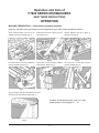
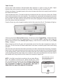
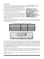
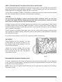
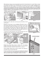
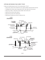
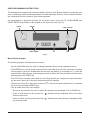
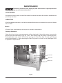
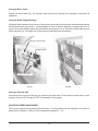
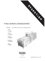
FT900 SERIES DISHWASHERS
MODELS
ML-110668-U covers all of the following models:
FT900
FT900BD
FT900S
FT900SBD
FT900D
FT900DBD
FT900SD
FT900SDBD
FT950
FT950BD
701 s. RIDGE AVENUE
TROY, OHIO 45374-0001
937 332-3000
www.hobartcorp.com
FORM 44095 Rev. B (Jan. 2013)
Table of Contents
Operation. . . . . . . . . . . . . . . . . . . . . . . . . . . . . . . . . . . . . . . . . . . . . . . . . . . . . . . . . . . . . . . . . 3
Machine Preparation . . . . . . . . . . . . . . . . . . . . . . . . . . . . . . . . . . . . . . . . . . . . . . . . . . . . . . 3
Tank Filling. . . . . . . . . . . . . . . . . . . . . . . . . . . . . . . . . . . . . . . . . . . . . . . . . . . . . . . . . . . . . . 4
Dishwashing. . . . . . . . . . . . . . . . . . . . . . . . . . . . . . . . . . . . . . . . . . . . . . . . . . . . . . . . . . . . . 5
Empty Strainer Baskets During Operation as Necessary. . . . . . . . . . . . . . . . . . . . . . . . . . . 6
Loading. . . . . . . . . . . . . . . . . . . . . . . . . . . . . . . . . . . . . . . . . . . . . . . . . . . . . . . . . . . . . . . . . 6
Unloading. . . . . . . . . . . . . . . . . . . . . . . . . . . . . . . . . . . . . . . . . . . . . . . . . . . . . . . . . . . . . . . 6
Recommended Minimum Temperatures. . . . . . . . . . . . . . . . . . . . . . . . . . . . . . . . . . . . . . . . 6
Cleaning. . . . . . . . . . . . . . . . . . . . . . . . . . . . . . . . . . . . . . . . . . . . . . . . . . . . . . . . . . . . . . . . 7
Cleaning the Top Duct. . . . . . . . . . . . . . . . . . . . . . . . . . . . . . . . . . . . . . . . . . . . . . . . . . 9
Cleaning the Blower-Dryer Air Filter . . . . . . . . . . . . . . . . . . . . . . . . . . . . . . . . . . . . . . 10
Dos and Don'ts for Your New Hobart Dishwasher. . . . . . . . . . . . . . . . . . . . . . . . . . . . . . 10
Curtains and Drainback Pans, Model FT900 and FT950. . . . . . . . . . . . . . . . . . . . . . . . . . 11
Curtains and Drainback Pans, Model FT900D. . . . . . . . . . . . . . . . . . . . . . . . . . . . . . . . . . 12
Curtains and Drainback Pans, Model FT900S. . . . . . . . . . . . . . . . . . . . . . . . . . . . . . . . . . 13
Curtains and Drainback Pans, Model FT900SD. . . . . . . . . . . . . . . . . . . . . . . . . . . . . . . . . 14
Machine Operation and Programming Security Levels . . . . . . . . . . . . . . . . . . . . . . . . . . . 15
User Programming Instructions . . . . . . . . . . . . . . . . . . . . . . . . . . . . . . . . . . . . . . . . . . . . . 16
Menu Display Prompts . . . . . . . . . . . . . . . . . . . . . . . . . . . . . . . . . . . . . . . . . . . . . . . . 16
Entering the Parameters Menu. . . . . . . . . . . . . . . . . . . . . . . . . . . . . . . . . . . . . . . . . . 17
Navigating the Parameters Menu. . . . . . . . . . . . . . . . . . . . . . . . . . . . . . . . . . . . . . . . 17
Parameters Menu . . . . . . . . . . . . . . . . . . . . . . . . . . . . . . . . . . . . . . . . . . . . . . . . . . . . 18
Communications Setup Menu. . . . . . . . . . . . . . . . . . . . . . . . . . . . . . . . . . . . . . . . . . . 19
MAINTENANCE . . . . . . . . . . . . . . . . . . . . . . . . . . . . . . . . . . . . . . . . . . . . . . . . . . . . . . . . . . . . . 20
Line Strainers. . . . . . . . . . . . . . . . . . . . . . . . . . . . . . . . . . . . . . . . . . . . . . . . . . . . . . . . . . . 20
Lubrication . . . . . . . . . . . . . . . . . . . . . . . . . . . . . . . . . . . . . . . . . . . . . . . . . . . . . . . . . . . . . 20
Motors. . . . . . . . . . . . . . . . . . . . . . . . . . . . . . . . . . . . . . . . . . . . . . . . . . . . . . . . . . . . . 20
Conveyor Gearmotor. . . . . . . . . . . . . . . . . . . . . . . . . . . . . . . . . . . . . . . . . . . . . . . . . . 20
Conveyor Drive Chain. . . . . . . . . . . . . . . . . . . . . . . . . . . . . . . . . . . . . . . . . . . . . . . . . 21
Conveyor Shaft Flange Bearings . . . . . . . . . . . . . . . . . . . . . . . . . . . . . . . . . . . . . . . . 21
Conveyor Take-Up Unit. . . . . . . . . . . . . . . . . . . . . . . . . . . . . . . . . . . . . . . . . . . . . . . . 21
Conveyor Speed Adjustment . . . . . . . . . . . . . . . . . . . . . . . . . . . . . . . . . . . . . . . . . . . . . . . 21
TROUBLESHOOTING . . . . . . . . . . . . . . . . . . . . . . . . . . . . . . . . . . . . . . . . . . . . . . . . . . . . . . . . 22
©
Manual Reset Button on Pump Motors, Conveyor Motor and Blower-Dryer Motor. . . . . . 22
HOBART 2013
–2–
Operation and Care of
FT900 SERIES DISHWASHERS
SAVE THESE INSTRUCTIONS
OPERATION
MACHINE PREPARATION — Check before beginning operation.
Open the machine doors and make sure all components are in their proper operating positions.
Pump Intake Screens must be put on
holders at each pump intake (Fig. 1).
Strainer Pans must be in place on top of
each tank (Fig. 2).
Strainer Baskets must be in place in
Strainer Pans (Fig. 3).
Fig. 1
Fig. 2
Fig. 3
End Caps must be correctly installed at
ends of all Wash Arms (Fig. 4).
Wash Arms must be properly installed
and latched in place (Fig. 5).
The Flush Arm at load end must be
properly installed (Fig. 6).
Fig. 4
Fig. 5
Fig. 6
The Final Rinse Arm (and Dual Rinse Arm when
present) must be properly installed (Fig. 7).
Curtains and drainback pans must be in their
proper places, refer to pages 11 – 14.
Fig. 7
–3–
TANK FILLING
Assure proper water hardness. Recommended water hardness is 3 grains or less per gallon. Higher
hardness may cause excessive formation of lime scale. Chlorides must not exceed 50 ppm.
All water (and steam, if equipped) supply valves must be opened and the electric supply turned on before
the machine will function.
Close all drains and doors. The drain handles are located near the floor at the front of each tank. Rotate
drain handles clockwise to the vertical position. The prewash tank, powerwash tank and power rinse tank
(when equipped) and their respective drain handles are located towards the load end of the machine from
the control box. The drain handle for the dual rinse tank (when equipped) is located towards the unload
end of the machine from the control box.
Press the Power key on the keypad located on the lid of the control box (Fig. 8). The display will light up.
Fig. 8
If door(s) are not closed Door(s) Open displays. If all doors are closed, Tanks Filling ... displays and tanks
begin to fill. All tanks will be full in approximately 10 to 15 minutes. NOTE: Opening a door during the
fill cycle shuts off the fill valves (Door(s) Open displays). Close the door to resume the fill cycle (Tanks
Filling ... displays).
When all tanks are full the fill valves will automatically shut off and the water temperatures display for
each tank. The full time Auto-Fill feature adds water to the tanks to maintain proper water levels during
operation.
After the water level raises the lower float in each tank, the wash, rinse and dual rinse tanks, if equipped,
begin to heat. If the water level drops below the lower float in any tank, the heat shuts off and filling resumes
on the affected tank(s). When the water level reaches the lower float, heating resumes while the tank(s)
continue(s) filling until the proper water level is reached. If the water level drops below the lower float in
the prewash tank, filling resumes until the water level reaches the upper float.
NOTE: A red light is provided on machines with an electric BlowerDryer. The operator is alerted by the lighted red light (Fig. 9) that
the over-temperature thermostat has been activated. If light stays on
for more than 5 minutes, the operator should turn the machine
off, disconnect power to the machine, and have it
serviced by a qualified service technician.
Electric Blower-Dryer, does not
have an ON / OFF Switch, but does
have a Red Indicator Light
! WARNING
If red indicator lights:
• Disconnect from power supply
• Have unit serviced by qualified
technician
RED
ly
t On
Ligh
Fig. 9
–4–
DISHWASHING
Start the motors for the conveyor, pumps and blower-dryer
(if equipped) by pressing the green START switch located
at either the load or unload end of the machine (Fig. 10) or
on the control box (Fig. 11). The machine will operate only
if the tanks have filled to the proper level and all doors are
closed. Press the red STOP switch (Fig. 10 or 11) to stop
the conveyor, pumps and blower-dryer motors.
STOP (red) and START (green) Switches
(push-button) are located on the load and
unload ends of the machine.
STOP
(red)
All tank temperatures display on the keypad display when
the machine is in operation. Final Rinse temperature reads
– – – until ware reaches the rinse zone. When ware
reaches the rinse zone, the Final Rinse water temperature
displays. After the ware exits the rinse zone, Final Rinse
temperature again reads – – – .
START
(green)
Fig. 10
Alternative Temperature Display Names — Table A, below, shows the possible temperature names
that may appear on the keypad display. The Long Name is equivalent to the Short Name. Displays
vary for different FT900 models.
Alternative Temperature Display Names — Table A
Indicated Temperature
Long Name
Short Name
PreWash Tank
PreWash
PW
Wash Tank
Wash
Wsh
Power Rinse Tank
Rinse
Rns
Dual Rinse Tank
DualRinse
DR
Final Rinse
FinalRinse
FnlRns
Fig. 11
If ware reaches the unload end of the machine and trips the dish limit switch, the conveyor and final
rinse shut off, and the display alternates between the tank temperatures and Unload Dishes. After
ware is removed and the dish limit switch resets, normal operation resumes. If ware is not unloaded
and the dish limit switch does not reset, the Dish Limit Auto-Timer counts down for one minute, then
shuts off pumps and blower-dryer. The display continues to alternate between the tank temperatures
and Unload Dishes. Unloading ware will reset the dish limit switch allowing the machine to
automatically resume normal operation.
If no ware enters the machine for a preset amount of time, the Auto-Timer automatically shuts off the
machine. Tanks continue to heat and temperatures (tanks, not final rinse) display. To resume
operation, press the green START switch located at either end of the machine or on the control box.
NOTE: The Auto-Timer shut off setting can be adjusted by your Hobart service technician; the range
is from 1 to 12 minutes.
–5–
Empty Strainer Baskets During Operation as Necessary
The Strainer Baskets must be emptied periodically during operation to prevent them from over filling,
which would adversely affect dishwasher operation. STOP the machine and open the access doors;
Strainer Baskets are immediately inside at the front of the tanks.
On Dual Rinse machines (FT900D or FT900SD) the strainer pan is located inside the machine behind
the control box area. Remove and clean the strainer pan periodically.
Loading
Pre-scrap dishes thoroughly to remove large food particles and debris. Never use steel wool
on ware to be loaded into the dishwashing machine; this could introduce surface corrosion
which could eventually interfere with machine operation.
All plates, saucers, trays, etc. should be loaded on the conveyor in an inclined position. Bowls should
be loaded upside down. Silverware must be washed in racks to prevent loss of items unless the
optional silverware conveyor is used; failing to do so could cause the conveyor to jam and damage
ware or machine components.
DO NOT attempt to wash large items (pots, pans, trays, etc.) without first checking to make sure they
will fit through the machine opening. Such items must not be washed in this dishwasher unless they
will easily pass through it.
Do not allow foreign objects to enter the unit, especially metallic contaminants.
UNloading
Remove dishes from the conveyor. If a dish
pushes against the conveyor trip arm (Fig. 12),
the conveyor stops and the pumps run for one
minute before shuting off.
Unload the conveyor starting with the ware
furthest from the trip arm. Remove the dish
that is striking the trip arm last. The machine
automatically restarts.
TRIP ARM
Fig. 12
Recommended Minimum Temperatures
The water temperatures in the tanks and rinse arms are monitored electronically and are displayed
on the control box keypad display. The display should be checked periodically to assure that proper
temperatures are being maintained.
NOTE: Refer to the hot water sanitizing label on the right side of the control box for minimum
temperature ratings.
–6–
CLEANING
The dishwasher MUST be thoroughly cleaned at the end of each working shift or after each meal.
Push the Power key on the keypad to turn the machine OFF.
Disconnect electrical power supply(ies) and follow lockout / tagout procedures
before you begin cleaning.
Open all front access doors. Drain the machine by rotating the drain handles counterclockwise to
a horizontal position. Drain handles are located near the floor at the front of each tank. On Dual
Rinse machines (FT900D or FT900SD) the dual rinse tank drain handle is located to the side of
the control box on the unload end of the machine. Draining the tanks requires approximately
5 to 10 minutes.
Remove and clean the curtains. Before removing strainer baskets and pans, clean the interior and all
tank shelves using a good hose with spray nozzle (Figs. 13 – 15). Flush all debris toward the strainers.
Fig. 13
Fig. 14
Fig. 15
Remove the wash arms by first releasing the latches (Fig. 16). Slide upper arms forward, swinging
front of arm down (Fig. 17). Slide lower arms forward, tilt front of arms upward to allow water to drain.
Remove arms. Remove end caps (Fig. 18). Clean wash arms in a sink.
Fig. 16
Fig. 17
Fig. 18
Remove the flush arm at the load end of the machine (Fig. 19). Remove end cap. Clean flush arm and
nozzles in sink. Remove the strainer baskets (Fig. 20) and strainer pans (Fig. 21). Also remove the
dual rinse strainer if present. Empty strainers in trash receptacle or food waste disposer. DO NOT
STRIKE STRAINER PANS OR STRAINER BASKETS ON SOLID OBJECT TO DISLODGE DEBRIS. Scrub
strainer pans and strainer baskets in a sink.
Fig. 19
Fig. 20
–7–
Fig. 21
When tanks are empty, remove pump intake screens (Fig. 22) and clean them in a sink. Remove, clean
and replace the strainer(s) from drainback pans in the power rinse and / or wash section(s) where
present (Fig. 23), refer to pages 11–14. Remove the dual rinse arms (FT900D or FT900SD only).
Clean debris from metal dual rinse nozzles and arms using a straightened paper clip (Fig. 24). Do not
attempt to clean Opti-Rinse final rinse nozzle(s). Opti-Rinse nozzle(s) should be replaced if they
become clogged or if the spray pattern is ineffective. Never use steel wool to clean warewasher
surfaces. Use only products formulated to be safe on stainless steel.
STRAINER
Fig. 22
Fig. 23
Fig. 24
Flush tanks with a water hose, removing any accumulation of food
soil (Fig. 25).
Reinstall all end caps; do not overtighten. Reinstall all arms in
their proper location and orientation. The Flush arm nozzles must
point horizontal toward the prewash tank. Upper arm nozzles
point downward, and lower arm nozzles point upward. Arms in the
prewash chamber each have two tubes (the slightly longer arm
goes below). The arms with five tubes fit in the upper brackets, and
the arms with four tubes fit in the lower brackets.
To install arms, slide manifolds on the guides toward the rear of the
machine (Fig. 26). Then latch arms in place (Fig. 27).
Fig. 25
CLEAN SENSOR OPENINGS
AT LOAD END OF MACHINE
Fig. 26
Fig. 27
Replace the pump intake screens, strainer pans, and strainer
baskets. Rehang the curtains (refer to pages 11 – 14). Leave the
machine doors open to allow the interior to air out and dry.
Clean machine exterior like any other stainless steel appliance.
Use damp cloth and mild soapy water.
Flush the openings where the sensors are located at the load end
of the machine (Fig. 28). Do not attempt to clean these openings
with any metallic object as damage to sensors can occur.
–8–
Fig. 28
CLEANING THE TOP DUCT
Disconnect electrical power supply(ies) and follow lockout / tagout procedures
before you begin cleaning.
Debris and airborne particles will settle on the Top Covers and the surfaces inside the Top Duct. The Top
Duct should be cleaned about every two weeks, as appropriate for your location. There are two handles
on each of the removable Top Covers so they can be lifted or moved to access the inside of the Top Duct
for cleaning (Fig. 29).
Before draining and cleaning the machine, perform the following cleaning task. Use an appropriate ladder
and both hands to remove each Top Cover. Clean inside the Top Duct with mild detergent / warm water
solution and brush, cloth, or sponge. Clean the Top Duct from the Unload End of the machine towards the
Load End. If necessary, the Top Duct may be hosed down. Rinse with clean water. Clean both sides of
the Top Covers individually while they are removed. After cleaning the Top Duct and the Top Covers,
replace each Top Cover in its correct location.
After cleaning the Top Duct, clean the dishwasher as discussed on pages 7 – 8.
TOP DUCT
TOP COVER REMOVED
BOTTOM OF DUCT
Fig. 29
–9–
CLEANING THE BLOWER-DRYER AIR FILTER
At least twice each month, the air filter
(when present, Fig. 30) on the blower-dryer
should be removed and cleaned in a sink
with warm soapy water and hosed off with
clean water. The air filter can be washed in
the dishwasher and flushed with clean water
after washing. Replacement air filters are
available — contact Hobart service.
BLOWER-DRYER FILTER
LIFT UP AND PULL FORWARD
TO REMOVE
R – L OPERATION SHOWN
Fig. 30
DOs AND DON'Ts FOR YOUR NEW HOBART DISHWASHER
DO assure proper water hardness of 3 grains or less per gallon.
DO pre-scrap dishes thoroughly.
DO use only detergents recommended by your chemical professional.
DO at the end of the day, thoroughly cleanse the machine, rinse, and dry (leave doors open).
DO closely follow your chemical professional's prescribed deliming schedule.
DO use only products formulated to be safe on stainless steel.
DO NOT over soften water (recommended water hardness range is 3 grains or less per gallon).
DO NOT use detergents formulated for residential dishwashers.
DO NOT allow food soil to accumulate on the tank bottom.
DO NOT exceed chemical manufacturer's recommended concentrations for detergent, rinse aid, or
lime scale remover.
DO NOT use steel wool to clean ware or dishwasher surface.
DO NOT allow foreign objects to enter the unit, especially metallic contaminants.
NOTE: Failure to follow use, care, and maintenance instructions may void your Hobart dishwasher
warranty.
– 10 –
CURTAINS AND DRAINBACK PANS, MODEL FT900 AND FT950
Curtains and drainback pans must be in their proper places, Fig. 31 . . .
• Hang a short curtain on the unload side of each upper prewash, wash and power rinse arm.
• Hang a long curtain on both sides of every section joint.
• Hang two long curtains at the load end.
• Hang one long curtain at the unload end.
• Drainback pan locations are shown for reference only.
Fig. 31
– 11 –
CURTAINS AND DRAINBACK PANS, MODEL FT900D
Curtains and drainback pans must be in their proper places, Fig. 32 . . .
• Hang a short curtain at the unload side of every upper prewash, wash, power rinse and dual
rinse arm.
• If equipped with a blower-dryer, hang another short curtain after the final rinse arm.
• Hang a long curtain on both sides of the prewash / wash section joint and the wash / power rinse
section joint.
• Hang two long curtains at the load end.
• Hang one long curtain at the unload end.
• Drainback pan locations are shown for reference only.
FT900D
R TO L OPERATION
8' CENTER SECTION
SHORT CURTAIN
ONLY WHEN
BLOWER-DRYER
IS PRESENT
FINAL RINSE ARM
DUAL RINSE ARM
POWER RINSE ARM
WASH ARM
FOUR SHORT
CURTAINS
AT UNLOAD SIDE
OF UPPER ARMS
THREE PAIRS OF
LONG CURTAINS
ONE LONG CURTAIN
AT UNLOAD END
LOAD
UNLOAD
DUAL RINSE
DRAINBACK PAN
TWO LONG & TWO SHORT
DRAINBACK PANS
STRAINERS
FT900D
L TO R OPERATION
8' CENTER SECTION
WASH DRAINBACK PAN
FINAL RINSE ARM
DUAL RINSE ARM
PREWASH ARM
PREWASH ARM
WASH ARM
POWER RINSE ARM
SHORT CURTAIN
ONLY WHEN
BLOWER-DRYER
IS PRESENT
FOUR SHORT
CURTAINS
AT UNLOAD SIDE
OF UPPER ARMS
THREE PAIRS OF
LONG CURTAINS
ONE LONG CURTAIN
AT UNLOAD END
TWO LONG & TWO SHORT
DRAINBACK PANS
WASH DRAINBACK PAN
Fig. 32
– 12 –
STRAINERS
DUAL RINSE
DRAINBACK PAN
CURTAINS AND DRAINBACK PANS, MODEL FT900S
Curtains and drainback pans must be in their proper places, Fig. 33 . . .
• Hang a short curtain on the unload side of each upper prewash and wash arm.
• Hang a long curtain on both sides of every section joint.
• Hang two long curtains at the load end.
• Hang one long curtain at the unload end.
• Drainback pan locations are shown for reference only.
FT900S
R TO L OPERATION
4' CENTER SECTION
FINAL RINSE ARM
WASH ARM
PREWASH ARM
TWO SHORT
CURTAINS
AT UNLOAD SIDE
OF UPPER ARMS
THREE PAIRS OF
LONG CURTAINS
ONE LONG CURTAIN
AT UNLOAD END
UNLOAD
LOAD
ONE SHORT
DRAINBACK PAN
ONE LONG
DRAINBACK PAN
FT900S
L TO R OPERATION
4' CENTER SECTION
FINAL RINSE ARM
PREWASH ARM
WASH ARM
TWO SHORT
CURTAINS
AT UNLOAD SIDE
OF UPPER ARMS
THREE PAIRS OF
LONG CURTAINS
ONE LONG CURTAIN
AT UNLOAD END
LOAD
UNLOAD
ONE SHORT
DRAINBACK PAN
Fig. 33
– 13 –
ONE LONG
DRAINBACK PAN
CURTAINS AND DRAINBACK PANS, MODEL FT900SD
Curtains and drainback pans must be in their proper places, Fig. 34 . . .
• Hang a short curtain at the unload side of every upper prewash, wash and dual rinse arm.
• If equipped with a blower-dryer, hang another short curtain after the final rinse arm.
• Hang a long curtain on both sides of the prewash / wash section joint.
• Hang two long curtains at the load end.
• Hang one long curtain at the unload end.
• Drainback pan locations are shown for reference only.
FT900SD
R TO L OPERATION
4' CENTER SECTION
SHORT CURTAIN
ONLY WHEN
BLOWER-DRYER
IS PRESENT
FINAL RINSE ARM
DUAL RINSE ARM
WASH ARM
PREWASH ARM
THREE SHORT CURTAINS
AT UNLOAD SIDE
OF UPPER ARMS
TWO PAIRS OF
LONG CURTAINS
ONE LONG CURTAIN
AT UNLOAD END
UNLOAD
DUAL RINSE
DRAINBACK PAN
FT900SD
L TO R OPERATION
4' CENTER SECTION
LOAD
ONE SHORT
DRAINBACK PAN
STRAINER
DUAL RINSE ARM
PREWASH ARM
FINAL RINSE ARM
SHORT CURTAIN
ONLY WHEN
BLOWER-DRYER
IS PRESENT
WASH ARM
THREE SHORT CURTAINS
AT UNLOAD SIDE
OF UPPER ARMS
TWO PAIRS OF
LONG CURTAINS
ONE LONG CURTAIN
AT UNLOAD END
LOAD
UNLOAD
ONE SHORT
DRAINBACK PAN
DUAL RINSE
DRAINBACK PAN
STRAINER
Fig. 34
– 14 –
MACHINE OPERATION AND PROGRAMMING Security Levels
The advanced digital controls on your dishwasher allow several setup and customization options.
Because these options can affect the operation of the machine, they are all locked-out by default from
the factory. To unlock them for editing, the security level must be elevated to an appropriate level.
It is recommended to keep the dishwasher in the lowest security level possible at all times. This will
prevent options from being inadvertently or intentionally modified from what is expected or acceptable.
The security level will automatically revert back to the lowest allowable level (either Operator or
SuperOperator, as described below) when any of the following occur:
1) No keys on the keypad are pressed for 10 minutes or more.
2) The machine is placed in Standby by pressing the POWER key.
3) An invalid Security Code is entered on the Enter Security Code? screen.
The following names and descriptions of the various security levels are listed from the lowest level to
the highest level. A higher security level includes all of the abilities of the lower levels plus some extra
abilities, as described below.
NOTE: The letter(s) to the right of the name are the same as the letter(s) you will see on the lowerleft of the Enter Security Code? screen. Refer to Entering the Parameters Menu for more details.
NOTE: The security level does not, by itself, affect the operation of the machine or inhibit the use of
any of the Start, Stop or Power keys or buttons. All of these basic functions are always available in
any security level.
Operator – O
This is the most basic security level and is the one that is enabled by default when the unit is powered
up as initially set by the factory. No security code is required to enter this security level. This level only
allows entering of the Security Code to elevate the current security level to something higher.
SuperOperator – SO
This security level can be set up to be the default level when the unit is powered up, instead of the
Operator security level. If it is set up to be the default level, the Operator security level will not
be accessible until SuperOperator Access is disabled by a manager or by Hobart Service. The
SuperOperator level does not require a security code to be entered by the user, but is only accessible
if enabled by a manager or by Hobart Service.
A SuperOperator is granted access to a few of the menu options, but not as many as in the Manager
security level. The available options for a SuperOperator are described in the Parameters Menu —
Table 1 and the Communications Setup Menu — Table 2, described above.
A manager or Hobart Service technician can enable or disable this security level via the SuperOp.
Access parameter. Refer to Navigating the Parameters Menu for more details.
Manager – M
This security level is the highest level attainable by the user. It requires the Manager Code to be
entered before the security level will be elevated to Manager.
This security level offers unrestricted access to all of the options listed in the Parameters Menu —
Table 1 and the Communications Setup Menu — Table 2, above. Because of this, it is recommended
that power to the machine be cycled off and on when access to the Manager level options are no longer
explicitly needed.
The Security Code for the Manager level can be changed by a kitchen manager or anyone with the
Manager Code. The default code is listed in the section titled Entering the Parameters Menu. As such,
it is recommended that this code be changed from the default and stored in a safe place where all
kitchen managers, but no one else, can access it. If the code is ever lost or forgotten, it can be reset
by Hobart Service.
NOTE: Having Hobart Service reset the Manager Code is not covered under either the basic or the
extended warranty.
– 15 –
USER PROGRAMMING INSTRUCTIONS
The dishwasher is equipped with electronic digital controls to allow greater precision for cleaning your
ware, maintaining required tank temperatures and other advanced functions. Some of these functions
are customized to suit the needs of your kitchen operation.
All customization is performed through the on-screen menu using the UP, DOWN / MENU and
START / ENTER keys located on the keypad on the control box door (Fig. 35).
POWER
DISPLAY
START or ENTER
UP
DOWN or MENU
STOP
Fig. 35
Menu Display Prompts
The following prompts are used inside the menus.
• The UP and DOWN keys are used to change parameter values and to navigate the menu.
• The ENTER key is used to accept a value, perform a specified action or enter a submenu. Pressing
this key while in the menu will not start the conveyor and pumps (if not already on). To start the
machine while editing a menu, press the green button on either end of the machine or exit the menu
before pressing the start key.
• The STOP key will always cancel what you are doing, discard any changes you have made since
the last save, return you to the main screen and stop the machine.
•
• The text just to the left or right of the circle icon ( ) on the screen shows what action or command
will occur by pressing the ENTER key.
• The up / down arrow icon in the display:
°Shows the line on which the value or menu will change when pressing the UP or DOWN key.
° A pair of solid arrows on the second line ( ), indicates that the displayed value is the value
° A pair of hollow arrows on the second line (
stored in the control.
not yet been stored.
), indicates the value has been changed but has
– 16 –
Entering the Parameters Menu
NOTE: The parameters can be changed anytime the display is active, which is when the machine is
operating or in idle mode.
To enter the Parameters menu to edit options:
1)Press the MENU key from the main screen.
a. You will be prompted on-screen asking if you wish to exit the menu.
2)Press the UP or DOWN key repeatedly until you reach the Enter Security Code? screen.
3)Press the ENTER key to indicate that you want to enter the code.
a. You will now be prompted with Security Code: on the top line and a single digit and three
] on the bottom line.
asterisks [ 0
***
4) Use the UP and DOWN keys to change the digit of the Security Code to the appropriate value*.
* The default Security Code to enter Manager Mode is 1001. This code can be changed by anyone with this knowledge and
it is recommended to change it from the default. If the code is ever lost for some reason, it can be reset by Hobart Service.
NOTE: Resetting the code is not covered under your warranty, whether you are in the initial warranty period or in the extended
warranty period.
5)Press the ENTER key to move to the next digit to the right.
6) Repeat steps 4 and 5 for each digit.
a. After pressing ENTER on the fourth digit, you will immediately return to the Enter Security
Code? screen.
7) You will know you entered the code correctly if the letter in the lower left corner reads M. Refer
to Machine Operation and Programming Security Levels on page 15 for more details on other
letters that may appear.
a. If it does not match, repeat steps 3 through 7.
b. If it does match, continue to step 8.
8)Press the UP or DOWN keys repeatedly until you reach the Edit Parameters? screen.
a. If you do not see this screen after scrolling all of the way through, the security Code was not
entered properly. Repeat the steps starting from 2.
9)Press the ENTER key.
a. You are now in the Parameters edit menu; the display shows the first editable parameter.
Navigating the Parameters Menu
NOTE: The security level must be elevated to the Super Operator or higher to enter the Parameters
Menu. Refer to Machine Operation and Programming Security Levels on page 15 for more details.
Hobart believes that the default settings that leave the factory are suitable for the majority of kitchen
operations. However, there are cases where kitchen managers may find the need to change one or
more options (Parameters Menu — Table 1); the Parameters Menu allows these changes.
Within the Parameters Menu, the manager (or operator, in some cases) may modify factory default
settings. The menu structure and description of each option are detailed below. Please contact Hobart
Service if you are uncomfortable changing any setting or are unsure of which one(s) to change.
– 17 –
Parameters Menu
The Parameters Menu — Table 1 lists the parameter name, a short description, a list of possible values
the parameter can have, the factory default value based on the specific dishwasher model and the
security level required to access that parameter.
Parameters MENU — Table 1
Parameter
Name
Description
Model
Possible
Values
Default
Value
Security
Required
Conveyor Speed
Adjusts the speed of the conveyor in feet per
minute. Increasing the value can increase the
throughput of ware, but can decrease the ability
to sufficiently clean difficult items, such as food
particles cooked onto pots and pans.
FT900
FT900D
FT900S
FT900SD
FT950
4 – 8.5
4 – 8.5
4 – 6.3
4 – 6.3
4–5
8.5
8.5
6.3
6.3
5
SO
Low FR Temp
Alarm
Enables or disables a visual alarm on the display that
indicates that Final Rinse water temperature is below the
NSF required minimum of 180°F (82°C). When enabled, a
message will display notifying the user of this condition.
However, machine operation will not change and ware will
continue to run through the machine as expected. When
disabled, there will be no extra message indicating a
low-temperture event; however, the temperature display will
still show the current Final Rinse water temperature.
Enabled
or
Disabled
Disabled
M
SuperOp. Access
Enables or disables the SuperOperator access level.
When enabled, this allows any user to modify values in
the Parameters Menu that are marked as requiring only
SO security without entering a password. This can be
useful, for example, to allow the operator to adjust conveyor
speed based on the volume of dishes entering the dish
room without the need for intervention by a manager.
When disabled, the only operation allowed by any user is
the ability to enter the Security Code and exit the menu.
No parameters are allowed to be modified.
Enabled
or
Disabled
Disabled
M
Change Mgr. Code
Sets a new Security Code for elevating access to the
Manager Level.
It is recommended to change this from the default value
and store the new code where all kitchen managers, but no
operators, can access it.
0000
to
8888
1001
M
Edit
Communications
Setup?
Enters the Communications Setup submenu, where settings
for the NAFEM Data Protocol can be changed. Please refer
to Communications Setup Menu – Table 2 for more details.
M
Save Settings
and Exit?
Exits the Parameters menu and returns to the main screen.
Any settings that were changed are saved and most
become active immediately.
(If one or more settings are not active immediately, a
message will display indicating that you need to cycle
power to make them active.)
SO
Cancel Settings
and Exit?
Exits the Parameters menu and returns to the main screen.
Any settings that were changed are cancelled and revert
back to the previous saved values.
SO
– 18 –
Communications Setup Menu
The Communications Setup Menu — Table 2 lists the parameter name, a short description, a list of
possible values the parameter can have, the factory default value based on the specific dishwasher
model and the security level required to access that parameter.
COMMUNICATIONS SETUP MENU –— TABLE 2
Parameter
Name
Description
NAFEM DP Baud
Adjusts the baud rate of communication between the
dishwasher and a NAFEM Data Protocol (NDP) Gateway
(sold separately). This must match the setting in the NDP
Gateway.
Refer to documentation that came with the NDP Gateway
for instructions on where to find this value.
NAFEM DP ID
Adjusts the machine-specific ID for use on a NAFEM
Data Protocol network.
Each device on the network must have a unique ID.
Please refer to any documentation that came with other
NDP-compliant devices to verify that all IDs on the network
are unique.
Exit to Params?
Exits the Communications Setup menu and returns to the
Parameters menu. Any settings that were changed are
only saved by choosing the Save Settings and Exit? option
on the Parameters menu.
Changing communication values typically requires the
machine power to be cycled.
– 19 –
Possible
Values
Default
Value
Security
Required
9600
to
38,400
9600
M
1
to
247
5
M
MAINTENANCE
Disconnect electrical power supply(ies) and follow lockout / tagout procedures
before performing any maintenance procedure.
Line Strainers
Line strainers used in water or steam lines should be cleaned one week after machine installation and
periodically thereafter.
LUBRICATION
A list of acceptable lubricants, as well as the lubricants themselves, are available from your local Hobart
Service Office.
Motors
All motors have sealed bearings and require no lubrication maintenance.
Conveyor Gearmotor
Check the oil level in the conveyor gearmotor at the unload end of the machine every six months by
removing the gear case fill-plug (Fig. 36). The oil level should be at the bottom of the fill-plug hole.
Draining the gear case can be achieved by removing the Drain Plug (Fig. 36) and capturing and
recycling the drained oil. After rescrewing the Drain Plug back in the hole, use only Mobilgear # 630
to replenish or replace the oil.
GEAR CASE
FILL PLUG
DRAIN PLUG
Fig. 36
– 20 –
Conveyor Drive Chain
Inspect the drive chain (Fig. 36) regularly and lubricate as required with Hykogeen Concentrate A
(supplied).
Conveyor Shaft Flange Bearings
Located at both load and unload ends of the machine and at the front and back, these bearings should
be lubricated every four months. Grease fittings at each of the four bearings, a grease gun and 16
ounces of Chevron SRI #2 grease are provided for this purpose. Fig. 37 shows one of the take-up units
at the load end; Fig. 38 shows one of the conveyor bearings at the unload end.
CONVEYOR TAKE-UP UNIT
GREASE FITTING
GREASE
FITTING
LUBRICATE GUIDES
Fig. 37
Fig. 38
Conveyor Take-Up Unit
Lubricate the two conveyor take-up unit guides at the load ends of the machine at least twice a year
using the Chevron FM Grease Alc Ep 2, provided for this purpose.
Conveyor Speed Adjustment
The conveyor speed comes preset from the factory. Conveyor speed can be adjusted to run faster or
slower by the customer. Refer to User Programming, pages 15 – 19.
– 21 –
TROUBLESHOOTING
Manual Reset Button on Pump Motors, Conveyor Motor and Blower-Dryer Motor
In case any motor becomes overheated, the thermal
overload will cause the motor to not operate. A
manual reset button is provided on the junction box
for each motor. To restart after the motor is allowed
to cool, press the manual reset button on the motor
junction box (Fig. 39). If motor(s) continue to trip,
contact Hobart service.
MOTOR RESET BUTTON
Fig. 39
SYMPTOM
POSSIBLE CAUSE
NOTE: If symptom(s) persist after possible causes have been checked, contact
Hobart Service.
Machine Won't Operate 1. Blown fuse or tripped circuit breaker at power supply.
After Start Button is
2. Inspection door(s) not closed, Door(s) Open displays.
Pressed.
3. Conveyor may be jammed.
4. Check drains, make sure they're closed. Check tanks, make sure they're full.
Ware Not Clean.
1. Insufficient pre-scraping or tank water may need to be changed.
2. Missing end plug from wash arm.
3. Wash arm nozzle obstruction.
4. Water leaking past manifold O-ring.
5. Loss of water pressure due to pump obstructions.
Disconnect electrical power supply(ies) and follow
lockout / tagout procedures. Drain tank(s) and check for any obstructions
at the pump intake.
6.Incorrect water temperature. Check circuit breaker to electric heat supply, or
main steam valve. Make certain valve is completely open.
7. Incorrect detergent dispensing. Contact your chemical representative.
8. Manual overload on pump motor(s) may have tripped.
9. Wash arms installed incorrectly.
10. Ware not loaded properly.
Leaking Vacuum
Breaker.
1.Foreign material or corrosion could be preventing proper valve operation. Shut
off all incoming water supply line(s). Unscrew and lift bonnet from valve body.
Clean valve and reassemble.
– 22 –
SYMPTOM
POSSIBLE CAUSE
Spotting of Ware.
1.Ware not loaded properly.
2.Incorrect final rinse water temperature (minimum 180°F) or inadequate water
pressure (15 to 25 psi is recommended).
3.Incorrect rinse aid dispensing. Contact your chemical representative.
4.Improper water hardness (3 grains or less per gallon is recommended).
5.Incorrect detergent for water type.
6.Clogged rinse nozzle(s).
7.Misaligned rinse arms. Rinse arms should be positioned so that they align in
hub on chamber wall.
Inadequate Rinse.
1.Dirty line strainers causing reduced water flow. Turn off water supply, remove
strainer cap, withdraw and clean screens.
2.Low supply line pressure.
3.Rinse Arm(s) are not properly inserted in the hubs.
4.Clogged Dual Rinse Nozzle(s) on FT900D or FT900SD — clean the Nozzle(s).
5.Dual Rinse Tank Strainer Pan is clogged on FT900D or FT900SD — clean
the Strainer Pan.
Continuous Rinse
Operation
1.Photoelectric sensors are blocked. Clean sensor openings (Fig. 40).
2.Remove side panels from load end of machine adjacent to prewash chamber.
With machine power on, verify indicators on sensor (Fig. 41) flash on and off
when blocking and unblocking the sensor.
3.Improperly operating rinse solenoid valve. Contact Hobart Service.
4.Problems with conveyor motor drive. Put machine in Standby (by pressing the
Power key) for at least 60 seconds to allow drive and motor to fully discharge
and reset. Turn machine back on. If problem persists, contact Hobart Service.
NOTE: If symptom(s) persist after possible causes have been checked, contact
Hobart Service.
CLEAN SENSOR OPENINGS
AT LOAD END OF MACHINE
ELECTRONIC SENSOR
AT LOAD END
Fig. 40
Fig. 41
– 23 –
SYMPTOM
POSSIBLE CAUSE
Tanks Not Heating.
1.Low water safety devices shut off heat. Check for proper water level.
2.Lower float(s) do not move freely.
3.Circuit breaker(s) to heat system tripped (electric heat).
4.Steam supply valve(s) are not opened completely or supply pressure too low
(steam heat).
5.Overtemp protector tripped (electric heat). Contact Hobart Service.
6.Failed heating element (electric heat). Contact Hobart Service.
7.Bucket trap not functioning correctly (steam heat). Contact Hobart Service.
8.Improperly operating steam solenoid valve(s) (steam heat). Contact Hobart
Service.
No Fill or Slow Fill.
1.Door(s) are open.
2.Main fill (water supply valve) could be closed.
3.Upper and / or lower fill floats do not move freely.
4.Dirty line strainer (Fig. 42) causing reduced water flow. Turn off water supply,
remove strainer cap, withdraw and clean screens.
5.Problem with solenoid valve. Contact Hobart Service.
6.Low incoming water supply pressure.
7.Drain(s) open.
No Blower-Dryer Heat
(Electric Heat BlowerDryer).
1.Blower or motor not operating properly.
2.Circuit breaker to electric blower-dryer heaters tripped.
3.Overtemp protector tripped; red overtemp indicator light is lit. Contact Hobart
Service.
No Blower-Dryer Heat
(Steam Blower-Dryer).
1.Blower or motor not operating properly.
2.Improperly operating steam solenoid valve (when equipped).
3.Steam supply valve is not completely open or supply pressure is too low.
5.Bucket trap not functioning correctly.
6.Missing or dirty filter.
NOTE: If symptom(s) persist after possible causes have been checked, contact
Hobart Service.
LINE STRAINER
PL-41182-1
Fig. 42
– 24 –
SYMPTOM
POSSIBLE CAUSE
Display Reads
Possible Resolution
Door(s) Open
Close all inspection doors.
Unload Dishes
Remove all ware from unload section of the machine, starting with the ware closest
to the machine chambers. Finally remove the last ware that is in contact with the dish
limit bar.
Temp Err - [Tank Name]
Ensure lower float assembly in indicated tank is not visibly damaged and sufficient
water is in the tank to cover the lower float.
Fnl Rinse Temp Low
1.If problem is intermittent and only occurs after the machine has been idle for
several minutes, this is normal. The problem will correct itself after running several
pieces of ware through the machine.
2.Check that the final rinse booster tank circuit breaker is on and not tripped (if
equipped.)
3.Check that the final rinse booster tank overtemp circuit is not tripped (if equipped).
4.Ensure that the building supply water to the final rinse booster tank is at least
the minimum specified by Hobart.
5.If temperature control needs adjustment, or if there is a booster heater failure,
contact your local Hobart Service office.
Temp Err - Fnl Rns
Ensure that the supply water valve to the final rinse booster is open.
Check Water Level
1.Ensure all drains are closed and free of debris.
2.Check that water supply valve is open
3.Open inspection doors and check water level of all tanks. Water should be about
1 inch down from top of strainer pan or higher. Do not forget to check the water
level of the dual rinse tank (models FT900D or FT900SD) which is located behind
the control box directly beneath the final rinse arms. Close inspection doors.
4.If tanks fail to fill after another 20 minutes, contact Hobart Service.
Reset Required
Place machine in Standby by pressing the Power key. Wait at least 60 seconds
before powering on the machine.
NOTE: If symptom(s) persists after possible causes have been checked, contact
Hobart Service.
– 25 –
– NOTES –
– 26 –
– NOTES –
– 27 –
FORM 44095 Rev. B (Jan. 2013)
– 28 –
DAY / SHIFT
TIME
PREWASH TANK
TEMPERATURE
WASH TANK
TEMPERATURE
POWER RINSE TANK
TEMPERATURE
Dual Rinse Tank
TEMPERATURE
FINAL RINSE
TEMPERATURE
COMMENTS /
RECORDED BY
DATE _______________________