1
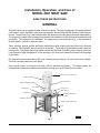
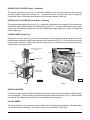
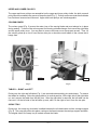
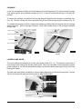
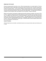
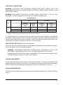
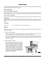
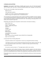
I
N
S
T
R
U
C
T
I
O
N
S
MODEL 5801 MEAT SAW
MODEL
5801
ML-38674
EXECUTIVE OFFICES
701 RIDGE AVENUE
TROY, OHIO 45374-0001
FORM 16322 Rev. A (11-95)
Installation, Operation, and Care of
MODEL 5801 MEAT SAW
SAVE THESE INSTRUCTIONS
GENERAL
The 5801 Meat Saw is rugged, durable, and easy to clean. The saw is equipped with a water resistant
3 HP electric motor and direct gear drive transmission that provides a blade speed of 3500 feet per
minute. The carriage (Fig.1) has stainless steel ball bearings providing easy travel and dependability.
The shaped front edge of the carriage is comfortable to the operator's body even when leaned on during
movement. The carriage lock is standard. The upper pulley cover and baffle (Fig. 1) are standard in
durable plastic, optional in stainless steel.
Table, carriage, pulleys, guides, and wiper assemblies can be quickly removed without tools for ease
of cleaning. Moving parts are enclosed but accessible. The blade is guarded above and below the
cutting zone. The pusher plate is provided to eliminate the need of handling items close to the blade;
it can ride on the right "flanged-end" of the carriage so you keep your hands away from the cutting edge
of the blade.
For electrical specifications above 250 volts, a transformer provides a 115 volt control circuit voltage.
Thermal overload protection is an option.
One long-life blade is furnished with each saw as standard equipment. This blade cannot be
resharpened; replacement blades are available through your local Hobart Service Office.
UPPER PULLEY COVER (SST)
SWITCH KNOB
COLUMN GUARD
UPPER GUIDE AND GUARD
TABLE (LEFT)
SAW BLADE
GAUGE PLATE
TABLE (RIGHT)
CARRIAGE
GAUGE PLATE HANDLE
LOCK LEVER
CARRIAGE LOCK
LOWER COVER (SCRAP PAN)
LEGS
FEET
PL-40830-1
Fig. 1
© HOBART CORPORATION, 1995
– 2 –
INSTALLATION
UNPACKING AND ASSEMBLY
Immediately after unpacking the meat saw, check for possible shipping damage. If the meat saw is
found to be damaged, save the packaging material and contact the carrier within 15 days of delivery.
Prior to installation, test the electrical service to make sure it agrees with the specifications on the
machine data plate located on the column.
Packed in a packet attached to the table compartment are the pusher plate and the gauge plate handle.
Place the pusher plate in its storage location under the carriage support (Fig. 2). Assemble the gauge
plate handle to the gauge plate support by screwing the stud into the threaded hole (Fig. 3).
LEVELING
Place the saw in its operating location. Using a spirit level, level the meat saw front-to-back and sideto-side by turning the threaded feet in or out.
HAND KNOB
SAW BLADE
CARRIAGE
CARRIAGE SUPPORT
GAUGE PLATE HANDLE
PUSHER PLATE
PL-40847-1
PL-40831-1
Fig. 2
Fig. 3
WARNING: DISCONNECT ELECTRICAL POWER AND PLACE A TAG AT THE DISCONNECT
SWITCH INDICATING THAT YOU ARE WORKING ON THE CIRCUIT.
SAW BLADE
The saw blade must be installed so the teeth point
to the right and down (Fig. 4).
UPPER GUIDE AND GUARD ASSEMBLY
Upper Guide
and Guard
When the saw is off, the hand knob (Fig. 4) can be
used to raise or lower the upper guide and guard
assembly so the cutting zone is only as high as
necessary for the piece being cut. The hand knob is
not loosened during raising or lowering — it should
remain tightly secure.
Hand Knob
PL-52107
Fig. 4
– 3 –
UPPER PULLEY COVER (Plastic - Standard)
The plastic upper pulley cover (Fig. 5) should be installed on the two hinge-retainers at the top and
securely latched at the bottom during use. To remove the plastic upper pulley cover for cleaning,
release the latch at the bottom and remove from the hinge-retainers at the top.
UPPER PULLEY COVER (Stainless Steel - Optional)
The stainless steel upper pulley cover (Fig. 1) should be installed on the two hinge pins of the stainless
steel upper pulley baffle and securely latched during saw use. To remove the stainless steel upper
pulley cover for cleaning, unlatch and open the stainless steel upper pulley cover; then, lift straight up
off the hinge pins.
LOWER COVER (Scrap Pan)
During use, the lower cover (Fig. 5) acts as a scrap pan, accumulating bone dust and debris from the
blade scrapers and pulley wiper that are located on the lower panel (Fig. 6). To remove the lower cover
(scrap pan) for cleaning, release the clip at the top; pull out and lift the lower cover from the groove
at the bottom of the lower panel.
UPPER PULLEY COVER
(PLASTIC)
LOWER GUIDE BLADE
TENSION
ADJUSTER
BLOCK
PULLEY WIPER
COLUMN GUARD
BLADE SCRAPERS
CARRIAGE
SAW BLADE
LOWER COVER
(SCRAP PAN)
CARRIAGE LOCK
PL-40848-1
PL--40833-1
Fig. 5
Fig. 6
BLADE SCRAPERS
Two blade scrapers wipe the blade during sawing to accumulate bone dust and debris inside the lower
cover (scrap pan). The left scraper points up and the right scraper points down (Fig. 6). After the blade
is removed, the scrapers can slide off their mounting blocks for cleaning.
PULLEY WIPER
The pulley wiper (Fig. 6) scrapes bone dust or debris from the lower pulley during use. The pulley wiper
can be removed for cleaning by springing the wiper up and sliding it off the pins.
– 4 –
UPPER AND LOWER PULLEYS
The upper and lower pulleys are assembled on the upper and lower pulley shafts; the latch on each
pulley should be seated in the groove of the pulley shaft (Fig. 7). Pulleys can be removed after the blade
has first been loosened and removed. Upper and lower pulleys are interchangeable.
COLUMN GUARD
The column guard (Fig. 5) covers the return loop of the moving blade and must always be in place
during sawing. To remove the column guard for cleaning or blade change, first remove the right table
and the upper pulley cover. You may want to remove the lower cover (scrap pan) as well. Then, lift
the column guard up to free it from the two drive-pin or shoulder-screw heads on the column that it
hangs from.
LATCH
SHAFT
SCRAP TRAY
PULLEY
PL-40832-1
PL-40835-1
Fig. 7
Fig. 8
TABLES — RIGHT and LEFT
During use, the right and left tables (Fig. 1) are secured underneath by pins and clamps. To remove
the tables for cleaning: Raise the gauge plate to its vertical position; lift the right side of the right table
up; and, remove the table from the two pins. After the right table is removed, the left table can be
removed: Lift the left side of the left table up; and, shift it to the right to free it from the two pins.
SCRAP TRAY
During use, the scrap tray should be installed between the left-hand table and the carriage support
(Fig. 8). The scrap tray slides into place, resting on the frame between the carriage support and table.
The angled side of the scrap tray is located nearest the blade.
– 5 –
CARRIAGE
In use, the carriage can roll back and forth between the left carriage stop (Fig. 9) and the right carriage
stop, assuming the spring loaded carriage lock (Fig. 5) has not locked the carriage in a stationary
position.
To remove the carriage, turn either of the carriage stops 90 degrees so the bumper is toward the rear
(Fig. 10). Roll the carriage off either end while lifting it free of the carriage support structure (Fig. 9).
To reinstall the carriage, hold the carriage so the bearings (underneath) are aligned with the carriage
support structure. Roll the carriage into place. Return the carriage stops so the carriage is stopped
at both ends.
CARRIAGE
RIGHT TABLE
LEFT CARRIAGE STOP
WITH BUMPER TOWARDS
THE REAR
UPPER GUIDE AND GUARD
LEFT TABLE
LEFT CARRIAGE STOP
CARRIAGE SUPPORT
PL-40837-1
PL-40836-1
Fig. 9
Fig. 10
LOWER BLADE GUIDE
The lower blade guide assembly fits in the lower guide holder (Fig. 11). The blade fits in the slots of
both the steel saw blade guide and the plastic guide. When the right table is removed and the plastic
guide is hinged up, the lower blade guide assembly can be removed for cleaning by lifting it out of the
lower guide holder.
The steel saw blade guide is available in various widths depending on the blade being used. Contact
Service to change the steel saw blade guide for other blade widths.
LOWER BLADE GUIDE ASSEMBLY
LOWER GUIDE HOLDER
Fig. 11
– 6 –
PL-40838-1
REMOVING THE BLADE
Remove the upper and lower pulley covers. Raise the gauge plate to its vertical position. Remove
the right table by lifting its right side and sliding the table to the right to free it from the locating pins.
Remove the column guard. Turn the tension adjuster counterclockwise until it stops (this will release
tension on the blade by raising the lower pulley). Raise the plastic blade guide on the lower blade guide
assembly and release the blade from the upper and lower blade guides. Free the blade from the blade
scrapers in the lower pulley area and release it from the pulleys. Remove the blade.
Make sure the pulleys are properly installed and the pulley latches are seated in the groove of the
pulleys. Install the new blade with the teeth pointing to the right and down as you face the front of the
saw. The blade must fit between the V's on the blade scrapers, in the slots of the upper and lower blade
guides, and must not touch any of the pulley flanges. The lower blade guide must be installed after
the blade is installed. When the blade is in position, see BLADE TENSION, below, to adjust the tension
properly. Refer to LOWER BLADE GUIDE, page 6, if the blade width of the new blade is different than
the old. Reinstall any removed parts.
BLADE TENSION
After the blade has been installed, set the blade tension by turning the tension adjuster clockwise until
it stops.
– 7 –
ELECTRICAL CONNECTIONS
WARNING: ELECTRICAL AND GROUNDING CONNECTIONS MUST COMPLY WITH THE
APPLICABLE PORTIONS OF THE NATIONAL ELECTRICAL CODE AND/OR OTHER LOCAL
ELECTRICAL CODES.
WARNING: DISCONNECT ELECTRICAL POWER SUPPLY AND PLACE A TAG AT THE
DISCONNECT SWITCH INDICATING THE CIRCUIT IS BEING WORKED ON.
ELECTRICAL DATA
Fuse
Model
5801
Volts / Hertz / Phase
Circuit Breaker
Minimum
Circuit Ampacity
AMPS
Maximum
Fuse Size
AMPS
Minimum
Circuit Ampacity
AMPS
Maximum
Circuit Breaker Size
AMPS
230 / 60 / 1
25
25
30
30
200 - 230 / 60 / 3
20
20
20
20
460 / 60 / 3
15
10
15
15
Compiled in accordance with the National Electrical Code, ANSI / NFPA 70, 1993 Edition.
A 7/8" diameter hole for 1/2" trade size conduit is located in the lower area of the base. Use watertight
connections. Refer to Electrical Data, the machine data plate, and the wiring diagram located on the
machine when making the electrical connection. Connect the electrical power supply leads to the
pigtail leads; use copper wire rated at least 60°C for the connection.
CHECK MOTOR ROTATION (Three-Phase Machines)
If the motor does not rotate so the teeth of the saw blade run downward as you look at the cutting zone,
correct the rotation using the following procedure:
WARNING: DISCONNECT ELECTRICAL POWER SUPPLY AND PLACE A TAG AT THE
DISCONNECT SWITCH INDICATING THAT YOU ARE WORKING ON THE CIRCUIT.
Interchange any two of the incoming power supply leads. Reconnect the power supply and turn
the saw momentarily on and off to verify correct rotation.
CONTROL BOX HEATER
The meat saw has a heater in the control box to keep the controls dry. The heater is automatically ON
when the machine is electrically connected. The meat saw should be connected to the power supply
EXCEPT when performing assembly, disassembly, cleaning, or maintenance on the saw.
CLEAN SAW BEFORE USE
The saw must be thoroughly cleaned and sanitized after installation and before use. Refer to Cleaning,
page 11.
– 8 –
OPERATION
SAFETY DEVICES INCORPORATED IN THIS SAW MUST BE IN THEIR CORRECT OPERATING
POSITIONS ANYTIME THE SAW IS IN USE.
SAFETY FEATURES
Upper Guide and Guard Assembly
Before turning the saw on, raise or lower the upper guide and guard assembly by grasping the hand
knob and sliding up or down so the cutting zone is only as high as necessary for the piece being cut.
Doors, Covers, and Guards
All doors, covers, and guards must be in their operating position (closed) while the machine is running.
Pusher Plate
Always keep hands well back from the blade and maintain control of the product. Use the pusher plate
as described (page 10) and it will be unnecessary to hold your hand near the cutting edge of the saw
blade.
CONTROLS
Switch Knob
PULL turns the saw On. PUSH turns the saw Off.
SAWING
Place product on carriage. Set the upper guide and guard assembly and the gauge plate before
starting the machine.
If using the traveling carriage . . .
Stand in front of machine. Lean lightly against the front of the carriage as you move the carriage
to the left, passing the product through the blade at a steady and uniform rate.
Use your left hand to remove and stack cuts, always reaching behind the blade. NEVER REACH
IN FRONT OF THE BLADE. Return the carriage to the right, pulling the product toward you and
away from the blade.
If using the stationary carriage . . .
The carriage may be locked in a stationary
position by pulling the spring loaded carriage
lock out, rotating it 90° and sliding the carriage
until the lock engages (Fig. 12). To unlock the
carriage, pull the carriage lock out and rotate it
90° so it rests on its bracket. When sawing with
stationary table, observe the same safety
procedure of reaching behind the blade when
removing or stacking product. NEVER REACH
IN FRONT OF THE BLADE.
UPPER GUIDE AND GUARD
CARRIAGE
CARRIAGE LOCK
PL-40839-1
Fig. 12
– 9 –
GAUGE PLATE
When making several cuts of the same thickness (or when using the pusher plate), set the gauge plate
as desired (Fig. 13) by pushing the lock lever and sliding the gauge plate to the thickness you want.
A reference scale on the table indicates the thickness of cut. If the gauge plate is not needed, you may
release the lock lever and move the gauge plate to the rear; or raise the gauge plate to a vertical position
to keep it out of the way.
GAUGE PLATE
REFERENCE SCALE
PUSHER PLATE
CARRIAGE
GAUGE PLATE HANDLE
RIGHT CARRIAGE STOP
GAUGE PLATE LOCK LEVER
PL-40840-1
Fig. 13
PUSHER PLATE
The pusher plate is used to hold meat against the gauge plate when slicing short ends. A slot in the
pusher plate and a stop on the right "flanged-end" of the carriage is provided for proper positioning of
the pusher plate (Fig. 13). Hold the pusher plate handle with your right hand and always maintain a
safe distance from the blade. When not in use, keep the pusher plate under the carriage support
(Fig. 2).
– 10 –
CLEANING AND SANITIZING
WARNING: DISCONNECT ELECTRICAL POWER AND PLACE A TAG AT THE DISCONNECT
SWITCH INDICATING THE CIRCUIT IS BEING WORKED ON BEFORE CLEANING THIS MACHINE.
The saw must be thoroughly cleaned and sanitized:
Before first use;
After each day's operation;
Anytime it is not to be used for an extended period of time; or
Before being put into operation after an extended downtime.
The meat saw can be cleaned with high-pressure cleaning equipment (available from other suppliers)
or it can be disassembled and its components cleaned in a sink. In either case, a neutral pH cleaning
agent mixed per the supplier's instructions should be used. After washing, thoroughly sanitize, rinse,
and dry the saw and all components.
Disassemble the following saw components to allow access to all areas for cleaning . . .
Upper Pulley Cover
Lower Cover (Scrap Pan)
Tables — Right and Left-Hand
Scrap Tray
Carriage
Column Guard
Pulley Wiper
Blade Scrapers
Lower Blade Guide Assembly
Saw Blade
Upper Guide and Guard Assembly (unscrew Hand Knob to disassemble)
Upper and Lower Pulleys
If using High-Pressure Cleaning Equipment . . .
Scrape the machine and its components to remove any scrap particles before cleaning.
Thoroughly hose the saw and its components following the equipment supplier's instructions. Be
sure to get the hose stream into all corners. Stubborn soil may require a little brushing.
If using Sink Cleaning . . .
Use a cloth or brush on base unit. Thoroughly wash, sanitize, rinse, and dry.
Before reassembly, a light coating of tasteless mineral oil should be applied to all metal surfaces.
Lubricate six ball bearings on the carriage with a small amount of mineral oil. Apply a few drops of
mineral oil to the gauge plate slide rod and work the gauge plate assembly back and forth a few times.
Reassemble the saw components in reverse order of disassembly making sure all parts are properly
assembled.
– 11 –
MAINTENANCE
WARNING: DISCONNECT ELECTRICAL POWER SUPPLY AND PLACE A TAG AT THE
DISCONNECT SWITCH INDICATING THE CIRCUIT IS BEING WORKED ON.
LUBRICATION
The motor has permanently lubricated ball bearings and requires no additional lubrication.
The slide bar for the upper guide and guard assembly also requires no lubrication.
Occasionally, you should apply a small amount of mineral oil to the six ball bearing rollers underneath
the carriage.
On a more frequent basis, the gauge plate slide rod and the pulley shafts need a few drops of tasteless
mineral oil.
CHANGING SAW BLADES
If changing saw blades, disassemble components as described in REMOVING THE BLADE, page 7, and the
instructions for any component throughout the manual. Make sure wipers, scrapers, and all other
components are properly reassembled. Refer to BLADE TENSION, page 7. Refer to LOWER BLADE GUIDE ,
page 6.
SERVICE
Contact your local Hobart Service Office for any repairs or adjustments needed on this equipment.
FORM 16322 Rev. A (11-95)
– 12 –
PRINTED IN U.S.A.