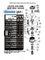
1
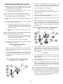
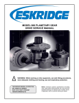
65E PLANETARY GEAR DRIVE with integral brake
SERVICE AND REPAIR MANUAL
!
WARNING: While working on this equipment, use safe lifting procedures, wear adequate clothing and wear hearing, eye and respiratory protection.
This service manual is effective
From:...... S/N 55013, june 2002
To:............ CURRENT
Ref:......... SM65EibD2-Ab
65esinglestageexplodedviewDrawing
2
integralbrakeexplodedDrawing
3
Lubrication & Maintenance
Using the chart below, determine an appropriate lubricant viscosity. Use only EP (extreme pressure) or API GL-5 designated lubricants.
Change the lubricant after the first 50 hours of operation and at 500 hour intervals thereafter. The gear drive should be partially disassembled to inspect gears and bearings at 1000 hour intervals.
Recommended ambient and operating temperatures for conventional and
synthetic gear lubricants
-50
-25
0
25
50
75
100
125
150
175
200
225
250 F
107
121 C
80W90 conventional
75W90 conventional
85W140 conventional
Min Ambient/operating temp
Max Operating temp
Max Ambient temp
75W90 synthetic
80W140 synthetic
-45
-32
-18
-4
10
24
38
52
66
79
93
Note: Ambient temperature is the air temperature measured in the immediate vicintiy of the gearbox. A Gearbox exposed to the direct rays of
the sun or other radiant heat sources will operate at higher temperatures and therefore must be given special consideration. The max operating
temp must not be exceeded under any circumstances, regardless of ambient temperature.
If your unit was specified “shaft up” or with a “-Z” option, a grease zerk was provided in the base housing. For shaft-up operation, the
output bearing will not run in oil and must be grease lubricated. Use a lithium based or general purpose bearing grease sparingly every
50 operating hours or at regular maintenance intervals. Over-greasing the output bearing should be avoided as it tends to fill the housing
with grease and thicken the oil
ESKRIDGE MODEL 65E OIL CAPACITIES
Operating Position
Oil Capacity
Oil Level
Single stage
Double stage
Horizontal Shaft
2.25 pints / 1.1 liters
2.25 pints / 1.1 liters
To horizontal centerline of
gear drive
Vertical Shaft (Pinion Up)
2.5 pints / 1.2 liters
2.5 pints / 1.2 liters
To side port on gear drive
base
Vertical Shaft (Pinion Down)
2.5 pints / 1.2 liters
2.5 pints / 1.2 liters
To midway on upper/
primary gear set
ESKRIDGE PART NUMBER INTERPRETATION
Note: All non custom Eskridge Geardrives are issued a descriptive part number which includes information regarding the Model, means of shaft retention, base style, shaft style, input mounting, input shaft size, overall ratio and
various available options. For a detailed breakdown of this information, please refer to Eskridge product specification sheets found at: http://www.eskridgeinc.com/geardrives/gearprodspecs.html
Unit Disassembly Procedure
1)
1) Scribe a diagonal line across the outside of the unit from cover/
brake (6) to case (1) before disassembly to assure proper
positioning of pieces during reassembly.
Rotate the planet gears (10) to check for abnormal noise
or roughness in bearings (18) or planet shafts (8). If further
inspection or replacement is required, proceed as follows.
2) Drive roll pins (29) into planet shafts (8).
3) Press or drive planet shafts out of carrier (3).
4) Slide planet gears (10) along with planet washers (15) out of
primary carrier (3).
5) If planet bearings (18) must be replaced, they may now be
removed from primary planet gears (10).
6) Use 1/8 inch pin punch to remove roll pins (27) from planet
shafts.
7) Rebuild primary planet carrier assembly in reverse order using any needed new parts. Planet shafts (8) should be installed with chamfered end of 1/8 inch hole toward outside
diameter of carrier. This will aid in alignment of holes while
inserting roll pins.
2) Remove magnetic pipe plug (32) and drain oil from unit. Maximum drainage occurs when oil is warm.
3) Remove eight cover/brake bolts (24) and lockwashers (27).
4) Lift off cover/brake (6). The input shaft (12) and carrier thrust
washer (4) may be lifted out of carrier assembly.
5) Lift primary planet carrier assembly (3,8,10,15,18, & 29) out of
case.
6) The output shaft (13) and secondary planet carrier assembly
may now be removed as follows:
a)
The secondary planet carrier (2) spline is a press fit
onto output shaft (13) spline. Case (1) should be set on
a plate or table with output shaft protruding downward
through hole in table.
Secondary Planet Carrier Subassembly (Items 2, 5, 7, 9, 14, 15, 19, 22 & 28)
b) Loosen but do not remove shaft retaining cap screws
(25).
NOTE: Care should be taken not to damage output shaft or
injure your feet when shaft falls out of case.
c) Press output shaft out bottom of case by applying press
load to top end of capscrews (25). Remove capscrews
to allow shaft to pass through case.
d) Remove shim(s) (14) from top end of shaft (13).
7)
Secondary planet carrier assembly (2,5,7,9,15,19, 22 & 28)
may now be lifted out of case.
Output Shaft Subassembly
(Items 13, 20, 31)
1) Outer tapered bearing cone (20) may be removed using a
gear puller. If reusing old bearing cone, do not damage roller
cage by pulling on it.
2) To replace shaft seal (31) lubricate inner lip of new seal and
turn so that open side is facing upward. Slide seal down output shaft (13) all the way to gear teeth or until it fits snug over
seal diameter.
1)
Disassembly procedure is the same as previous section on
primary planet carrier subassembly (steps 1-4) except substitute these parts: secondary carrier (2), secondary planet
gears (9), planet bearings (19), secondary planet shafts (7)
and roll pins (28).
Reassembly
Primary Planet Carrier Subassembly (Items 3, 8, 10, 11, 15, 18 & 29)
1) Place carrier (2) with hub down as shown above. Place bearing retainer plate (5) in bottom of carrier. Insert secondary
planet gears (9).
2) Turn carrier (2) over while using the planet gears (9) to hold
retainer plate (5) in place.
3) Remove one planet gear (9) and insert a bearing (19). Install two washers (15) (one on either side of the planet gear).
Place in carrier and install planet shaft (7) and roll pin (26).
Repeat for two remaining gears.
NOTE: Press bearing onto hub by pressing on inner race
only. DON’T press on roller cage or it may damage bearing.
4) If tapered inner bearing cone (22) on hub of secondary carrier
(2) must be replaced, it may be removed using a gear puller.
Then, press a new bearing cone onto hub making sure bearing shoulder is tight against hub shoulder.
Case Subassembly
1) Inspect inner and outer bearing cups (21 & 23) and replace if
necessary.
2) Clean all foreign material from magnetic drain and fill plug
(32).
Brake Disassembly Procedure
The 10 inch integral brake is spring loaded (normally applied) and
requires hydraulic pressure to release. All brakes are individually
tested at the factory for function, leaks and static breakaway torque
and are tested to be within +/- 20% of rated torque. Because the
brake is integral with the gear drive, it is designed to run “wet.”
Brake holding torque will be affected by the actual lubricant used
but it is intended for operation with EP 80/90 gear oil. Orientation
of the gearbox also affects the performance of the brake. With
the gearbox mounted horizontally or vertically-pinion-up, the clutch
plates will be bathed in oil and the holding torque will be in the -20%
range. Withe the gearbox mounted in the vertical, output-down orientation, the brake plates will not run in oil and the holding torque
should be in the +20% range.
b)
Press the plate as far as it will go (about 1/16 inch) of
travel). This can be done with a hydraulic press or a
piece of (at least 1/2-13) all-thread, washers and hex
nuts through the middle of the brake.
c)
With backing plate (4) pressed away from the retaining
ring (8), start the retaining ring out of the groove by prying the end of it with a screwdriver.
d)
Grab the end of the retaining ring with your hands and
with a circular motion, work the retaining ring the rest of
the way out of the groove.
NOTE: The retaining ring (8) is normally under very high
spring load. DO NOT attempt to remove it without first releasing spring load by depressing the backing plate (4) as described above. Personal injury and/or damage to the brake
will result if this step is not followed.
2)
Remove springs (5).
3)
Remove piston (3) as follows: Apply low air pressure (20-30
psi) to the brake release port while holding one hand on top of
the piston (3). It is a good idea to first place a shop rag over
the piston. The air will force the piston (3) out of the case
(1).
4)
Remove the friction discs (6), separator plates (7), O-rings
(12,13) and back-up rings (10,11) and thrust washer (9) from
case (1).
Brake Specifications Table
Maximum
pressure
3000 psi
intermittent
3000 psi
continuous
maximum
speed
3000 rpm
intermittent,
no-load
2000 rpm
continuous
load
maximum
operating
pressure-
200°f
intermittent
170°f
continuous
oil volume required to release
brake
0.62 cubic
inches
seal fluid compatibility
mineral-based
hydraulic oil
1)
Remove retaining ring (8) as follows:
a)
Brake Inspection
With brake assembly oriented large end up as shown
in exploded view on page 3, apply downward force on
backing plate (4) to compress springs (5). Each spring
exerts about 300 pounds of force.
1)
Clean all parts prior to inspection.
2)
Case (1): Grooves for O-rings and retaining ring should be
clean and free of nicks and dings.
3)
Shaft (2): Should be free of heavy wear. Gear teeth should
show no signs of pitting or surface spalling. Spline on inside
and outside of shaft should not show any fretting wear beyond surface discoloration.
4)
Piston (3): Should be free of all scratches, nicks and dings on
the two diameters that seal against the O-rings in the case.
Only very minor scratches may be dressed with 600 grit and
finer paper to at least a 32 micro-inch finish.
5)
Backing plate (4): Shoulder that bears against retaining ring
(8) should be square and free of nicks and dings.
6)
Springs (5): May be reused if no signs of cracks or rust.
Springs do eventually fatigue and fail after many cycles so
it is always recommended that they be replaced during nonroutine servicing.
7)
Friction & separator plates (6 & 7): May be reused if not excessively worn. There should be 8 parts total in the friction
pack, 1 to 4 friction discs and 4 to 7 separator plates. The full
stack measures 0.800 inches new. Replace friction discs if
the full stack measures less than 0.775 inches height. This
height represents a 10% reduction in holding torque versus
“new”.
8)
Retaining ring (8): Should lay relatively flat and round in the
free state. Replace if height measures more than .25” when
checked on a flat surface of the 2 spiral coils do not lay one
on top of the other.
9)
Back-up and O-rings (10, 11, 12 & 13): It is recommended
that they be replaced during non-routine servicing. They may
be reused if replacements are not available only if they are
free of cuts and wear. Be sure to check all surfaces.
Unit Reassembly
1)
Install thrust washer (9) in case (1).
2)
Friction discs (6) may be installed dry or they may be prewetted with gear oil. A friction disc (6) should be placed in
the case (1) followed by a separator plate (7). Alternate with
friction discs (6) and separator plates (7) in exactly the same
order as they were removed. There must always be a separator plate (7) on the exposed (piston) end of the stack and a
friction disc (6) on bottom end of the stack.
Bearing Pre-Load Measurement and Setting:
DIM "A"
DIM "B"
NOTE: If a friction disc (6) is placed next to the piston (3) the
unit will overheat and fail.
3)
With the friction pack in place, align the splines of the friction
discs (6) using the shaft (item 12 from gearbox exploded
drawing). The shaft must be able to slip all the way through
the friction pack to the thrust washer (9).
4)
Install O-rings (12 & 13) such that they are nearest each
other with the back-up rings (10 & 11) to the outside.
5)
Lubricate the O-rings (12 & 13) and piston (3) with gear or
hydraulic oil. Gently slide piston (3) into case (1) using heel
of both hands as far as it will go. Recheck spline alignment
of friction discs with shaft (item 12 from gearbox exploded
drawing). Using a mallet or light force, press the piston into
the case (1) until it drops below the retaining ring groove.
6)
Install springs (5) into the piston (3). They must be evenly
spaced such that the spring force is always balanced sideto-side.
7)
Set backing plate (4) with stepped side up, on top of springs
(5) in case (1). Set the retaining ring (8) on stepped lip of
the backing plate (4). Using hydraulic press or suitable apparatus (mentioned above), press and hold the backing plate
(4) as far as it will go below retaining ring groove. Refer to
detailed view in disassembly instructions (page 6).
8)
Using your hands, install the retaining ring (8) in its groove
in the case (1). Start one end into the groove and work the
rest of it into the groove with a circular motion. A flat-blade
screwdriver or awl may help in the installation but no other
tools should be needed. If the retaining ring doesn’t go freely
then the backing plate is not pressed in far enough into the
case (1).
9)
When installed, release the load against the backing plate
(4). Check that the ring is properly seated in the groove and
below the detent shoulder in the backing plate (4). Refer to
detail view in disassembly instructions (page 6).
1)
Install the secondary carrier assembly with the bearing (22)
installed, into the base (1) with cups (21 & 23) installed. Turn
this assembly upside down (outer bearing pointing up). Support the retainer plate (5) on a suitable support so the entire
assembly is free to rotate on the inner bearing on the support.
See the illustration above. Place the outer cone (20) into the
outer cup (21) and carefully spin this assembly 1-3 revolutions to allow the bearings to seat. Using a depth micrometer,
measure down from the outer bearing cone mounting surface
to the bottom surface of the retainer plate (5). Record this
measurement as A. Next, measure from the inner end of the
shaft (13), where the three threaded holes are located, to the
bearing seat. Record this measurement as B. Subtract A-B.
This number is the un-preloaded gap in the bearing stack.
The correct amount of pre-load is generally between 0.005
inch and 0.020 inch compression of the bearings. Add or remove shims to achieve the desired gap which will compress
or pre-load the bearings. Each shim is 0.005 inch thick. The
lower gap will produce rolling torque of 50-150 in-lb, the higher gap will produce rolling torques of 150-250 in-lb. Fewer
shims = tighter bearing pre-load, more shims = looser bearing
pre-load.
2)
Place the shaft seal (31) onto the seal-diameter of the shaft
(13). Press the outer bearing cone (20) onto the shaft; press
only on the race, not on the cage.
3)
Turn case pinion side up. Apply a layer of lithium grease to
outer bearing cup (21). Place the shaft (13) into case (1) so
that the shaft’s outer tapered bearing cone (20) is seated in
case’s outer bearing cup (21). Tap shaft seal (31) into place.
CAUTION: Shaft is not retained at this time.
10) Reinstall shaft (12, gear drive drawing or 2, brake drawing) and verify that it will insert through the brake to the thrust
washer (9). If not, apply pressure to the release ports to
disengage the brake. Shaft must insert all the way through
to the thrust washer (9) in order for the brake unit to install
properly on the geardrive.
4)
Turn case pinion side down.
5) Apply a layer of lithium grease to inner bearing cup (23).
6)
Install the correct number of shims (14), determined in step
1 onto the end of the shaft (13) with the holes lined up correctly.
7) Rotate bearing retainer plate (5) inside secondary carrier assembly so that counter-bored holes are centered between
planet gears (9).
NOTE: It is important that the holes in the retainer plate remain centered between planet gears. A certain amount of tool
clearance will be necessary in order to install and torque the
capscrews (25).
8)
Install secondary carrier assembly (2) into case (1) as follows: Rotate secondary carrier assembly back and forth until
planet gear teeth (9) mesh with gear teeth in case (1). Let
carrier assembly down until carrier spline touches output
shaft (13) spline. Rotate carrier by hand until you are certain carrier spline has started cleanly and squarely onto shaft
spline. View down through top of secondary carrier assembly
through counter-bored holes in retainer plate (5). If needed,
align holes in retainer plate directly over holes in the shaft
and shim(s) (14).
9) Counter-bored holes should be centered between planet
gears (9). Slowly press secondary carrier assembly down
tightly against output shaft (13).
NOTE 1: Rolling torque at proper bearing preload will vary according to the application. At output speeds of greater than 25
RPM, preload torque (including seal drag) should be in the range
of 50 to 150 in-lbs. At less than 25 RPM, rolling torque should be
150 to 250 in-lbs.
10) Tighten the socket-head capscrews (25) to a torque of 90 ftlb. Spin the gearbox case (1) on the shaft 2 to 3 revolutions.
Now re-tighten the capscrews (25) to a torque of 90 ft-lb. This
step allows the bearings to seat into their running position
and ensures the correct torque on the fasteners.
11) Place secondary thrust washer (4) onto center of secondary
planet carrier assembly.
12) Install sun gear (11) into center of secondary planet carrier.
13) To install primary planet carrier assembly hold inside diameter of carrier (3) and rotate until planet gears line up with case
gear teeth and sun gear. Assembly will drop into place.
NOTE: A simple planetary such as this does not require a gear
timing procedure.
14) Insert input gear (12) into unit so that teeth mesh with primary
planet gears (10).
15) Place carrier thrust washer (4) over input gear.
16) Place a new O-ring (30) on bottom of brake (6).
17) Set brake (6) on top of unit and refer to scribed line for proper
orientation. Install and torque eight cover bolts (24) with lockwashers (27) to 32 ft-lbs.
17) Check to be sure magnetic plug (32) is securely installed into
side of case (1).
18) Add gear oil as specified on page 2. Correct oil level will
measure to middle of primary planet gears (10) when in the
vertical operating position.
19) Install plug (15 from brake drawing) and install into oil fill
hole in brake (6).
20) Insert a shaft, such as an output shaft from a hydraulic motor,
into input gear (12), release brake and rotate by hand to be
sure unit turns smoothly and easily.
THE GEARBOX IS NOW READY FOR USE.