1
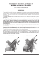
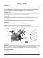
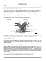
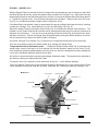
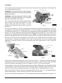
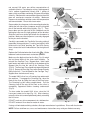
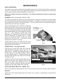
I
N
S
T
R
U
C
T
2812 SLICER
I
O
N
S
MODEL 2812 & 2912 SLICERS
MODELS
2812
ML-104958
2912
ML-104963
Previous models covered by this manual:
2812
2912
ML-104615
ML-104827
ML-104713
ML-104823
ML-104874
701 S. RIDGE AVENUE
TROY, OHIO 45374-0001
937 332-3000
www.hobartcorp.com
FORM 34454 (Feb. 2000)
Installation, Operation, and Care of
MODEL 2812 & 2912 SLICERS
SAVE THESE INSTRUCTIONS
GENERAL
The model 2812 and 2912 slicers are equipped with a 1⁄2 HP motor and are available for single-phase
electrical service. The slicer features the exclusive Hobart Stay-Sharp contoured cast solid stainless
steel knife. The slicer is furnished with a cord and plug as standard equipment. Other features and
options include:
The Power Interrupt feature, standard, requires the slicer to be manually re-started after a power
interruption.
The Gauge Plate and Carriage Interlock feature, standard, prevents the Carriage Tray from being
removed unless the Carriage is in the HOME position (pulled all the way to the front) and the Gauge
Plate is CLOSED. When the Carriage Tray is tilted horizontally, the slicer will turn OFF if it has not
previously been turned OFF. Once the Carriage Tray is tilted horizontally or removed, the slicer cannot
be started and the Gauge Plate cannot be opened until the Carriage Tray is returned to its normal
operating position.
The HomeStart feature, standard, requires the carriage to be in the H OME position before the slicer
can be started.
If equipped with the AutoShutoff option, the slicer will turn off if a full stroke of the carriage has not
been made within a 10 second interval. The AutoShutoff option is factory installed only.
The 2912 slicer features automatic slicing with six adjustable speeds.
A tubular food chute, 4" leg set and slaw tray are other available accessories for 2812 and 2912. The
low carriage fence is an accessory on 2812; it is standard on 2912. A high carriage fence is an
accessory used with front mounted meat grips. The standard meat grip is front-mounted. Heavy frontmounted meat grip is an available accessory.
Model 2812 Slicer
© HOBART CORPORATION, 1998
Model 2912 Slicer
–2–
INSTALLATION
UNPACKING
Immediately after unpacking the slicer, check for possible shipping damage. If the slicer is found to be
damaged, save the packaging material and contact the carrier within 15 days of delivery.
Prior to installing the slicer, test the electrical service to assure it agrees with the specifications on the
machine data plate. The data plate is located on the right side of the slicer base.
CARRIAGE TRAY
The Carriage Tray is secured to the slicer when the knob on the Carriage Tray / Support Arm is turned
clockwise until snug (Fig. 1). Refer to page 7 for assembly information.
SHARPENER
The Sharpener should already be mounted on top of the slicer and locked to its bracket (Fig. 1).
TOP KNIFE COVER
The Top Knife Cover should already be in place and secured with its Latch Knob (Fig. 1).
DEFLECTOR
The Deflector should already be mounted below the knife (Fig. 1).
FENCE (Low and High Fences are used with front-mounted meat grip only.)
Either Fence (Fig. 1) can be clamped on the Carriage Tray to limit product movement during slicing.
Model 2812
TOP KNIFE COVER
CARRIAGE TRAY
.
ew
Scr
b
y.
a
m
Tr
Thu
age
t
i
r
u
r
o
a
nC
ck
Ba
ce o
n
1.
e
F
Lay
FENCE
SHARPENER
DEFLECTOR
2.
CARRIAGE TRAY /
SUPPORT ARM
R
er
to V
e
t
a
ot
tica
Up
ce
Fen
e
Slid
3.
l.
ig
. T
h
Scr
ten
ew
.
PL-41408-1
Fig. 1
ELECTRICAL
WARNING: THIS MACHINE IS PROVIDED WITH A THREE-PRONG GROUNDING PLUG. THE
OUTLET TO WHICH THIS PLUG IS CONNECTED MUST BE PROPERLY GROUNDED. IF THE
RECEPTACLE IS NOT THE PROPER GROUNDING TYPE, CONTACT AN ELECTRICIAN.
CLEAN BEFORE USING
The 2812 or 2912 slicer must be thoroughly cleaned and sanitized after installation and before being
used. Refer to Cleaning, page 6.
–3–
OPERATION
SAFETY
SAFETY DEVICES INCORPORATED IN THIS SLICER MUST BE IN THEIR CORRECT OPERATING
POSITIONS ANYTIME THE SLICER IS IN USE.
The TOP KNIFE C OVER must be in position and secured with the LATCH KNOB (Fig. 2). The RING GUARD is
not removable. The D EFLECTOR, mounted below the slicer knife, can be removed for cleaning.
The MEAT GRIP (Fig. 2) must be used when slicing short ends to keep your hand(s) away from the knife.
When the slicer is not running, the INDEX KNOB (Fig. 2) must be turned back below zero (fully clockwise).
The GAUGE PLATE will then cover the knife edge.
Always UNPLUG the POWER CORD before cleaning or moving the Slicer.
Model 2812
TOP KNIFE COVER
CARRIAGE TRAY
FENCE
RETAINING CLIP
LATCH KNOB
GAUGE PLATE
MEAT GRIP
CARRIAGE TRAY HANDLES
INDEX KNOB
SWITCH KNOB
PL-41409-1
Fig. 2
WARNING: ROTATING KNIFE. USE FEED GRIP. UNPLUG MACHINE POWER CORD BEFORE
CLEANING, SERVICING, OR REMOVING PARTS. REPLACE PARTS BEFORE USE.
SLICING — MODEL 2812
With the Gauge Plate fully closed, pull the Carriage all the way toward you until it reaches its stop. With
the Meat Grip out of the way, place the product to be sliced on the Carriage Tray. Set the Meat Grip
against the product.
If the Meat Grip is not needed, it may be stored out of the way by rotating it behind the top of the Carriage
Tray where it can rest on the Retaining Clip (Fig. 2).
Adjust the Gauge Plate to obtain the desired slice thickness by turning the Index Knob (Fig. 2). The
numbers on the Index Knob do not indicate actual measurements but may be used for reference to
duplicate slice thickness. Turn the slicer on by pulling the Switch Knob (Fig. 2) forward until it starts
and then releasing it. Slicer will not stay on unless the gauge plate is opened first. Unless the Gauge
Plate is opened before pulling the Switch Knob on, the slicer will not continue to run when the Switch
Knob is released.
Use either Carriage Tray Handle (Fig. 2) to push the Carriage back and forth to slice.
Turn the slicer off by pushing the Switch Knob or by closing the Gauge Plate.
–4–
SLICING — MODEL 2912
With the Gauge Plate fully closed, pull the Carriage all the way toward you until it reaches its stop. With
the Meat Grip out of the way, place the product to be sliced on the Carriage Tray. Adjust the fence by
loosening the thumb screw and sliding the fence so that it is close to the product but not pushing against
it. Tighten the thumb screw. Set the Meat Grip against the product. Always make sure the Lever
(Fig. 3) is in the Manual position (down) before starting the slicer.
If the Meat Grip is not needed, it may be stored out of the way by sliding it to the top of its travel, rotating
it under the Carriage Tray, and allowing it to rest in the Retaining Clip (Fig. 3).
Adjust the Gauge Plate by turning the Index Knob (Fig. 3) to obtain the desired slice thickness. The
numbers on the Index Knob do not indicate actual measurements but may be used for reference to
duplicate slice thickness. Turn the slicer on by pulling the Switch Knob (Fig. 3) forward until it starts
and then releasing it. Unless the Gauge Plate is opened before pulling the Switch Knob on, the slicer
will not continue to run when the Switch Knob is released.
Use either Carriage Tray Handle (Fig. 3) to push the Carriage back and forth to slice manually.
Turn the slicer off by pushing the Switch Knob or by closing the Gauge Plate.
To operate the slicer in Automatic mode . . . Rotate the Speed Selector Knob (Fig. 3) to the desired
speed; make sure the Carriage is in H OME position (all the way forward); make sure the Lever (Fig. 3)
is on the Manual position (pointing down); turn the slicer on; start the carriage drive unit by rotating the
Lever to the Automatic position (up and to the right).
Any of the six speed selections can be used to begin Automatic mode. The speed can be adjusted at
any time by rotating the Speed Selector Knob.
To stop the drive unit, rotate the Lever down and to the left — to the Manual position.
To use the optional Food Chute, place the Meat Grip on the Retaining Clip, fit the hangers on the Food
Chute around the meat grip slide rod (at front), and lower the Food Chute onto the Carriage Tray.
Model 2912
LATCH KNOB
CARRIAGE TRAY
RETAINING CLIP
TOP KNIFE
COVER
SHARPENER
GAUGE PLATE
MEAT GRIP
SWITCH KNOB
CARRIAGE HANDLES
INDEX KNOB
SPEED SELECTOR KNOB
LEVER IN MANUAL (DOWN) POSITION
PL-41257-1
Fig. 3
–5–
CLEANING
This machine must be thoroughly cleaned and sanitized after each day’s operation or after being idle
for an extended period of time.
WARNING: THE SLICER KNIFE IS VERY SHARP.
EXERCISE EXTREME CAUTION WHEN WORKING
NEAR THE KNIFE.
LATCH KNOB
TOP KNIFE COVER
CARRIAGE TRAY
WARNING: UNPLUG MACHINE POWER CORD
AND TURN THE INDEX KNOB FULLY CLOCKWISE
BEFORE CLEANING THE SLICER.
Use a clean cloth soaked in mild detergent and warm
water to wipe all surfaces of the machine. Rinse
using a fresh cloth and clean water. Use only
products formulated to be safe on stainless steel or
aluminum.
KNOB
CARRIAGE TRAY /
SUPPORT ARM
PL-41258-1
Fig. 4
To clean the Carriage Tray, close the gauge plate and pull the Carriage all the way to the front. Unscrew
the Knob on the Carriage Tray / Support Arm (Fig. 4). Tilt the Carriage Tray / Support Arm to the right
until almost horizontal (Fig. 4). The Carriage Tray / Support Arm can be cleaned while in this horizontal
position, or it can be removed by grasping with both hands and lifting straight up. Once removed, the
Carriage Tray / Support Arm can be cleaned in a sink. NOTE: The last three digits of the slicer serial
number are etched on the Key (Fig. 8) so you can make sure the Carriage Tray stays with its own slicer.
Remove the Top Knife Cover by rotating the Latch Knob (Fig. 4) counterclockwise and lifting it free of
the guide pins. Remove the Deflector (Fig. 1) from its mount below the slicer knife by rotating
downward. Clean both Top Knife Cover and Deflector with warm soapy water in a sink. Rinse with
clean water.
SHARPENER
RING GUARD
KNIFE
KNIFE
GAUGE PLATE
PAPER TOWEL
GAUGE PLATE
PL-41403-1
LOCK LEVER
PL-41402-1
Fig. 5
Fig. 6
Remove the sharpener by pushing the Lock Lever to the left (Fig. 5). Tilt the right side up, clearing the
right guide pin, then lift the sharpener up, clearing the left guide pin. Wipe out any residue remaining
inside the sharpener housing and clean the sharpener in a sink. Rinse with fresh water.
Clean completely around the Ring Guard by working a moistened, folded paper towel between the Ring
Guard and Knife. Insert the towel at the base of the Ring Guard. Manually rotate the knife and the
towel will wipe the Ring Guard and the edge of the Gauge Plate as it follows the knife (Fig. 6).
Wash and rinse both sides of the knife by wiping outward from the center. Use a mild detergent or
sanitizer solution only. Never clean any part of the slicer with steel pads.
Do not exceed chemical manufacturer’s recommended concentrations for detergent or sanitizer. Do
–6–
not exceed 200 parts per million concentration of
available chlorine. For example, mixing 1 tablespoon of
5.25% sodium hypochlorite bleach with 1 gallon of
water yields a solution containing 200 ppm of available
chlorine. Solution with concentrations greater than 200
ppm will accelerate corrosion of metals. Maximum
exposure to sanitation solution varies with temperature
and concentration. Rinse with clean water.
Reassemble the sharpener to the mounting bracket by
sliding the left slot on the sharpener over the left guide
pin on the bracket while tilting slightly (Fig. 7). Then,
press down on the right side of the sharpener so the
locking hole fits over the right guide pin on the bracket.
Slide the Lock Lever to the right to lock the sharpener in
position. Make sure the sharpener is securely engaged
to the pins on the bracket.
SHARPENER
KNIFE
GAUGE PLATE
LOCK LEVER
PL-41402-1
Fig. 7
CARRIAGE TRAY /
SUPPORT ARM
KEY
Carefully reassemble the Top Knife Cover by putting it
in position (three guide pins). Lock by turning the Latch
Knob to the left while lowering the Top Knife Cover;
then, release the Latch Knob and turn it to the right until
snug.
CARRIAGE PIVOT
Guide
Replace the Deflector below the slicer knife:
bottom of socket onto mount and rotate upwards.
Make sure the digits etched on the Key (Fig. 8) match
the last three digits of the slicer serial number. To
reinstall the Carriage Tray / Support Arm: Hold it with
both hands and lower it so the Key at the bottom of the
Support Arm fits into the slot of the Carriage Pivot
(Fig. 8). The Carriage Tray should rest almost horizontal
(Fig. 4). Return the Carriage Tray to the Gauge Plate by
tilting to the left. Turn the Knob on the Carriage Tray /
Support Arm clockwise until snug.
The model 2812 slicer has a Cleaning Leg underneath
the machine. To engage the Cleaning Leg, raise the
front of the slicer by lifting the front of the slicer base.
The Cleaning Leg will swing straight down. Pull the
Cleaning Leg all the way to the front so the slicer is
completely supported before cleaning underneath
(Fig. 9).
PL-41248-1
Fig. 8
CLEANING LEG
PL-40866-1
Fig. 9
MODEL 2912 –
RAISED FOR CLEANING
LIFT LEVER –
RAISED PAST CENTER
To clean under the model 2912 slicer, raise the Lift
Lever past center to its stop (Fig. 10). After cleaning,
return the slicer to its normal position by slowly retracting
the Lift Lever.
DO NOT wash any slicer components in a dishwasher.
DO NOT immerse slicer base or motor in water.
PL-41259-1
Fig. 10
If using a chlorinated sanitizing solution, dilute per manufacturer’s guidelines. Rinse with fresh water.
NOTE: Failure to follow use, care, and maintenance instructions may void your Hobart warranty.
–7–
MAINTENANCE
KNIFE SHARPENING
The Hobart cast stainless steel knife will provide long service in normal food retail or commercial
kitchen use. However, in high volume applications where it is a practice to sharpen the knife frequently
or even daily, the knife will be expended in a shorter time.
Sharpen only when necessary; prolonged or too frequent sharpening results in unnecessary
knife wear.
WARNING: UNPLUG MACHINE POWER CORD.
Turn the index knob fully clockwise to close the gauge plate. Remove the Top Knife Cover by rotating
the Latch Knob counterclockwise and lifting it off the slicer. Thoroughly wash the area around the knife,
the exposed knife surfaces, and the knife edge. Fat from meat or cheese should not be allowed to
transfer from the knife to the sharpener.
Plug in machine power cord. With the carriage tray
pulled fully forward, start the slicer with your right
hand by pulling the start switch forward and holding
it out. If the sharpener handle is the type that does
not hang downwards, pull it fully forward for 5 seconds
(Fig. 11). If the sharpener handle does hang
downwards, lift it with your left hand until horizontal
and pull forward for 5 seconds (Fig. 11). Slowly
release the sharpener handle. Release the switch
knob to turn the slicer off. If necessary, repeat
sharpening for another 5 seconds.
TO SHARPEN:
PULL SHARPENER HANDLE
FULLY FORWARD
FOR 5 SECONDS
TOP KNIFE COVER
IS REMOVED
PL-41404-1
Unplug machine power cord. Wipe the slicer with a
clean damp cloth to remove any grinding particles.
Replace the Top Knife Cover.
Fig. 11
LUBRICATION — Carriage Slide Rod
Lubricate the Carriage Slide Rod with Lubriplate
FMO-200-AW oil (supplied). Either squirt 8 – 10
drops every 2 – 3 months (depending on usage) in
the Wick Hole on the Carriage Transport (Fig.12).
Or, once monthly, apply 4 – 5 drops directly on the
Carriage Slide Rod on each side of the Carriage
Transport (Fig.12).
To apply oil, pull out the telescoping tube on the oil
bottle, aim the tube, and squeeze gently on the
sides of the bottle. After applying oil, move the
Carriage Tray back and forth a few times so the oil
spreads over the entire length of the slide rod.
WICK HOLE
CARRIAGE SLIDE ROD
CARRIAGE TRANSPORT
PL-41146-1
Fig. 12
OVERLOAD RESET BUTTON — MODEL 2912
Push the reset button underneath the slicer near the right-front foot if the carriage motor overloads.
SERVICE
Contact your local Hobart-authorized service office for any repairs or adjustments needed on this
equipment.
FORM 34454 (Feb. 2000)
–8–
PRINTED IN U.S.A.