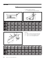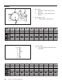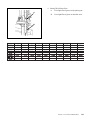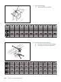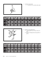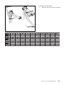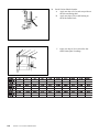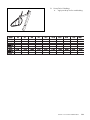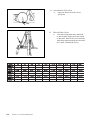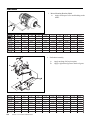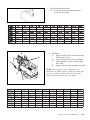
1
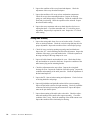
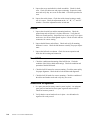
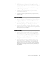
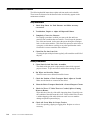
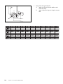
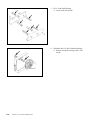
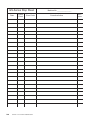
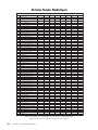
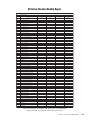
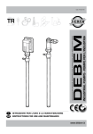
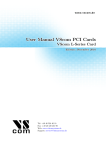
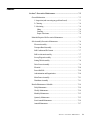
Contents
Section 7: Preventive Maintenance .................................................... 7-3
General Information ........................................................................... 7-3
1. Inspection (and correcting any problem found) ......................... 7-3
2. Cleaning .................................................................................. 7-4
3. Lubricating .............................................................................. 7-4
Oiling .................................................................................... 7-4
Greasing ................................................................................ 7-4
Proper Lubricants .................................................................. 7-4
Materials Required for Preventive Maintenance .................................. 7-5
Sub-Assembly Preventive Maintenance .............................................. 7-6
Elevator Assembly ....................................................................... 7-6
Transport Band Assembly ............................................................ 7-6
Ball Cushion and Pit Curtain ........................................................ 7-7
Ball Accelerator Assembly ........................................................... 7-7
Sweep Wagon Assembly ............................................................. 7-7
Setting Table Assembly ................................................................ 7-8
Drive Frame Assembly ................................................................ 7-9
Electrical ................................................................................... 7-10
Power Ball Lift .......................................................................... 7-10
Administration and Organization ................................................. 7-10
Main Frame Assembly ............................................................... 7-11
Distributor Assembly ................................................................. 7-11
Detailed Maintenance Schedule ....................................................... 7-14
Daily Maintenance ..................................................................... 7-14
Weekly Maintenance ................................................................. 7-14
Monthly Maintenance ................................................................ 7-15
Quarterly Maintenance .............................................................. 7-15
Semi-Annual Maintenance ......................................................... 7-16
Annual Maintenance .................................................................. 7-17
Section 7: Preventive Maintenance
7-1
Lubrication ...................................................................................... 7-18
Monthly .................................................................................... 7-18
Quarterly ................................................................................... 7-20
Semi-Annual ............................................................................. 7-34
Annual ...................................................................................... 7-37
Maintenance Forms ................................................................... 7-39
7-2
Section 7: Preventive Maintenance
Section 7: Preventive Maintenance
General Information
Preventive maintenance is the most important responsibility of the pinsetter
mechanic. Properly performed preventive maintenance will increase reliability,
prevent major breakdowns and lengthen the life of the pinsetter.
Preventative maintenance should begin when the pinsetters are installed.
Waiting until the pinsetters are dirty and operating poorly will create a situation
that can quickly become unmanageable.
Finally, it is a very poor practice to rely on memory in servicing any machinery.
An example of a typical work schedule is included that will allow you to track
the maintenance as it is being done. The following pages of this section list
step by step guidelines on what should be done and how often. Careful study
of the contents of this section and proper use of the work schedule will result in
clean, well operating machines and in addition, will greatly lengthen the useful
life of your pinsetters.
Tip: Combining the following activities during preventative maintenance
can save time, and effort.
In general preventative maintenance requires the following:
1. Inspection (and correcting any problem found)
The pinsetter should be inspected periodically for the following condition:
• Loose hardware
• Damaged or worn parts
• Cracked/fatigued metal or welds
• Proper adjustments
For optimum machine operation, a mechanic should correct any pinsetter problems such as loose hardware or adjustments immediately. If corrective action
cannot be done immediately it should be logged on the “pending work item “ form
for the machine.
In addition all pinsetter malfunctions should be recorded on the pinsetter “Stop
Sheet” that should be attached to the elevator of every machine. This form is
invaluable in determining the reliability and performance of your pinsetters.
Finally, if a problem is observed on a pinsetter, check the other pinsetters for the
same problem.
Section 7: Preventive Maintenance
7-3
2. Cleaning
The frequency for cleaning the pinsetter depends on the type and quantity of lane
conditioner (oil) used and the amount of bowling activity for the pinsetter.
In general the pinsetter should be kept as clean as possible using a vacuum,
general purpose cleaner, warm water (with detergent as needed), and invincible
cleaner.
3. Lubricating
Proper application of lubricants is essential for the operation and long life of the
pinsetter.
Oiling
Always use a metered oil can. This will prevent over oiling where extra oil will
drip off into the wrong area and cause problems, part failures or interfere with
bowling activity.
Greasing
It is always a good practice to wipe off the old grease and dirt it has collected
with it BEFORE applying a new coat of grease. Do not over grease the part as
the grease can get into areas that can cause problems or interfere with the
machine operation.
Proper Lubricants
Always use the proper lubricants such as those specified in the front of this
manual. Penetrating oils do not last long and leave parts exposed to premature
failure. Some lithium greases have a tendency to dry and harden quickly. This
can lead to sticky parts or premature failure.
7-4
Section 7: Preventive Maintenance
Materials Required for Preventive Maintenance
- Metric tool set
- Vacuum cleaner - tank style
- Small paint brush
- Cleaning cloths
- Bucket and scrubbing brush (and/or a scrubbing mop)
- Oil can with long rigid or flexible spout
- Lubricating oil (light machine oil - 30 weight non-detergent) - such as:
Brunswick Part No. 11-676353-000 (1 gallon container)
- Lubricating grease - medium duty non-lithium - such as:
Brunswick Part No. 12-700120-002 (3 each 3 1/2 oz. cartridges)
Brunswick Part No. 11-676305-000 (1 each 14 oz. cartridge)
Mobil “M-437-SL”
- Hydraulic Fluid - such as:
Brunswick Part No. 34-205052-000 (1 each 3 1/2 oz. can)
Mobil “DTE II”
- General purpose cleaner - a non-residue detergent type such as:
Brunswick GPC Part No. 62-860085-005 (5 gallon container)
- Brunswick Pinsetter Cleaner - Part No. 62-860083-005 (5 gallon container)
- Chain Lubricant - such as:
Lubriplate “Chain & Cable Fluid” (Part No. 634-205116-000)
Section 7: Preventive Maintenance
7-5
Sub-Assembly Preventive Maintenance
Elevator Assembly
1.
Inspect condition of the frame and frame welds. Check for loose or
missing hardware.
2.
Inspect all shafts, bearings, sprockets, chains and pulleys for condition
and adjustment. Check all pin shovels and shovel hardware. Inspect all
shovel pivot levers.
3.
Inspect condition and mounting of guards and verify guard identification labels are in place.
4.
Inspect the mounting and adjustment of the elevator control, (EC)
switch, as well as the mounting and function of Mechanic’s rear control
box, and trouble light. Verify that all elevator cables are intact and
routed correctly.
5.
Inspect the mounting hardware, condition and adjustment of the shark
assembly and pin guide wedges. Check the shovel cam for adjustment
and condition. Check the alignment and mesh of the drive gears.
Inspect the condition and operation of the shark fin. Inspect the
tensioning and condition of the transfer belts. Inspect the mounting
hardware and condition of the deflector shoe.
6.
Inspect the condition, alignment, adjustment and operation of the pin
count switch.
7.
Check the smart shark solenoid and solenoid linkage. Check for proper
operation of the smart shark. Check all mounting hardware and fasteners.
Transport Band Assembly
7-6
Section 7: Preventive Maintenance
1.
Inspect the condition of the welds and mounting hardware on the pit side
frames.
2.
Inspect the mounting hardware and condition of the transport band
boards. Check the condition and tracking of the transport band carpet.
Inspect the front and rear rollers for bearing and shaft condition, correct
tensioning and alignment in mounting slots. Inspect the condition and
operation of the centering guide rollers.
3.
Inspect the condition and tensioning of the transport band drive belts.
Inspect the mounting hardware on the idler and tensioner assemblies.
Check the condition of the idler pulleys.
4.
Inspect the condition and mounting hardware on the pin feed deflectors
and mounting brackets. Check the adjustment on the pin feed deflectors.
Ball Cushion and Pit Curtain
1.
Inspect the condition and mounting hardware on the ball cushion board
and the impact strips. Check the attachment of the rubber cushion to the
board and the facing to the rubber cushion. Inspect the cushion frame
welds, and check the mounting hardware. Inspect the nylon cushion
bearings for wear and check the location and hardware on the stop
collars. Inspect the cushion assembly for proper adjustment.
2.
Inspect the mounting, and adjustment of ball cushion shock absorber.
Inspect the mounting and location of the shock absorber adjustment
plate.
3.
Inspect the condition and mounting of the overflow chutes. Inspect the
condition and adjustment of the overflow socks.
4.
Inspect the condition of the pit curtain and check the mounting hardware.
Ball Accelerator Assembly
1.
Inspect the condition of the frame welds. Check that foot guards are in
place. Inspect the condition and location of the ladder.
2.
Inspect the condition and mounting hardware on the ball door protector
plate.
3.
Inspect the accelerator motor. Check for excessive vibration.
4.
Inspect the condition of the flat belt.
5.
Inspect the ball door and ball door locking mechanism for proper adjustment. Check the condition of the ball door, ball door button and door
locking bolt. Inspect the ball door solenoid for correct operation. Check
the routing of the solenoid cable. Verify that ball door shafts rotate
freely.
Sweep Wagon Assembly
1.
Inspect the condition of the sweep wagon frame and frame welds.
Check the roller mounting and adjustment. Check the conditions of the
pusher rods and pusher rod bushings. Inspect the conditions of the
protector blocks and block mounting hardware. Check all sweep wagon
hardware.
Section 7: Preventive Maintenance
7-7
2.
Inspect the condition of the sweep board and adapters. Check the
adjustment of the sweep board and adapters.
3.
Inspect the condition of all sweep release mechanism components.
Check all sweep release mounting hardware. Inspect for missing
springs or worn linkage and pivot bushings. Check the condition of the
chain and pivot bearing. Check the operation of the solenoid. Inspect
the solenoid cable routing.
4.
Inspect the sweep attenuator and sweep shock absorber for loose or
missing hardware. Check the attentuator and “G” switch for proper
adjustment. Inspect all pivot points for wear. Inspect the “G” switch
cable routing.
Setting Table Assembly
7-8
Section 7: Preventive Maintenance
1.
Inspect the setting table frame for wear or broken welds. Check for
loose or missing hardware. Check the vertical swing shaft stop bolt for
proper adjustment. Inspect the condition of the vertical helper springs.
2.
Check for loose or missing spotting tong and geared rack hardware.
Inspect the “ST” switch mounting and check the adjustment. Inspect the
condition of the tongs, gears and toothed racks. Check the operation of
the tongs and inspect the tong dampers for wear.
3.
Inspect all cable channels and conduits for wear. Check that all channels and conduits are secured to the frame. Inspect the condition of the
table harness plug and its mounting bracket.
4.
Check the adjustment on the stop collars. Inspect the swing shaft
bearings for wear. Inspect the condition of the table spring. Inspect the
condition and mounting of the table jam roller. Check the adjustment of
the horizontal stop bolt.
5.
Inspect the TS-1 jam switch mounting and adjustment. Check for loose
or missing hardware and springs.
6.
Inspect all pin holders and pin holder solenoids for correct mounting.
Inspect all pin holder switches for tight mounting. Check all pin holder
connectors and wiring for routing and connection. Inspect the adjustment on the pin detector plates.
7.
Inspect the mounting of the table racks to the table. Check the adjustment and condition of the small roller support assembly. Check the
condition of the T-stop. Check the mounting of the OOR actuator cam.
Inspect the condition of the chain and pivot bearing.
Drive Frame Assembly
1.
Inspect the welds and condition of the sweep shaft. Check the sweep
shaft supports for secure mounting. Inspect the sweep shaft bearings for
signs of wear. Inspect the connecting rods and verify all hardware is in
place and secure.
2.
Inspect the condition and welds on the left-hand and right-hand drive
frame assemblies. Check for loose or missing hardware. Inspect all
cable channels and cables for condition and routing. Check for any
worn shaft bearings. Check the chain tensioners for condition and
adjustment. Inspect the frame counter for correct operation.
3.
Inspect the spotting tong drive for loose or missing hardware. Check for
loose or worn gears. Check the spotting tong solenoid for proper
operation. Check the spotting tong clutch for correct operation, and
check the condition of the clutch shaft. Inspect the mesh between the
square shaft drive gear and the spur gear. Check the condition of the
square shaft drive gear.
4.
Inspect the motors for correct mounting and alignment. Check the
condition of all V-belts. Inspect the motor cables for correct routing.
Check the condition of the motor tensioning springs. Check all motor
mounting plate bushings. Check for excessive vibration in motor and belt
operation.
5.
Inspect the stroke limiter for a bent or cracked plate and loose or
missing hardware. Check the mounting of the stroke limiter shock
absorber. Check the condition of the rubber bumper. Check the solenoid for proper operation. Inspect the square shaft, the linkage and the
square shaft latch for correct adjustment.
6.
Inspect the condition of the double V-belts. Check for loose or missing
tensioner mounting hardware. Check the tensioner shaft and bearings
for loose or noisy operation.
7.
Inspect the condition of the setting table and sweep motor drive assemblies. Check for worn or damaged chains. Check for loose or missing
bearing plate hardware. Inspect the condition of bearing plate bearings
and drive sprocket shafts.
8.
Inspect the condition of the guide tower assembly. Check the mounting
and adjustment on the TS-2 and OOR switch. Check for correct switch
cable mounting. Check for loose or missing guide tower hardware.
Inspect the condition of the lift chain sprocket. Check the condition of
the jam lever and spring.
Section 7: Preventive Maintenance
7-9
9.
Inspect the sweep and table drive shaft assemblies. Check for shaft
wear. Check for chain wear and proper tensioning. Inspect the crank
arms and verify they are secure on the shafts. Check the sprockets for
wear.
10.
Inspect the switch cluster. Check the switch cluster housing to make
sure it is secure. Check the adjustment on the “A,” “B,” “C,” and “D”
switches. Check the adjustment on the switch cam.
Electrical
1.
Inspect the electrical box and box mounting hardware. Check the
ground strap and verify that it is in place and secure. Verify that all
cables are routed correctly. Inspect the box cover to verify it is in place
and secure. Are all box switch guards in place? Check all cable and box
connectors for correct seating.
2.
Inspect the ball detect and reflector. Check and verify all mounting
hardware is secure. Check the ball detector assembly for proper adjustment.
3.
Inspect the ball rack reset button. Check for correct operation and
check the cable routing and connection.
Power Ball Lift
1.
Check the condition and mounting of the ball lift tires. Check the
condition of the lift tire shafts and bearings. Check the condition and
operation of the ball lift clutch.
2.
Check the ball lift motor for correct mounting. Check the motor pulley
for proper alignment. Check the drive belt condition and alignment.
3.
Check the ball lift tracks for correct mounting. Check the condition of
the rubber and leather tracks and verify they are secure.
Administration and Organization
7-10
Section 7: Preventive Maintenance
1.
Is a spare parts and inventory control system in place? Are adequate
spare parts on hand and are those parts organized and accessible?
Check for inventory control.
2.
Verify that the correct hand tools are in place. Are the hand tools
organized for ready access?
3.
Verify that the correct cleaning and lubrication supplies are on hand.
Check and verify the supplies are adequate and that the correct approved
materials are in use.
4.
Is a preventive maintenance program in use? Is a lubrication program in
use? Is a cleaning program in use?
5.
Verify that current operations manuals, service parts manuals and
service bulletins are in the center.
6.
Verify that stop sheets, recap forms and frames per stop data is being
used in the center.
Main Frame Assembly
1.
Inspect the main frame. Check for wear points or broken welds. Check
for loose or missing hardware. Check the main support braces and
verify they are secure.
2.
Inspect the pinlight fixture. Check and verify that the fixture is secure.
Check the lamp and lamp sockets. Check the power cord routing.
3.
Inspect the guards. Check for wear points. Check for loose or missing
hardware. Check for any missing guards. Check the work platform and
the work platform braces and hardware.
Distributor Assembly
1.
Inspect the distributor frame assembly. Check for worn or damaged
frame components and welds. Check for loose or missing hardware.
Check and verify that the dust pan is secure. Check the distributor rails
and extensions for wear or cracks. Check the distributor stations for
wear or cracks. Inspect the lower pin guides for bent or missing parts.
Check the corner turn rails and corner pin turn devices for loose or
missing hardware and for correct adjustment.
2.
Inspect the distributor shafts, pulleys and belting. Check for worn or
damaged shafts or bearings. Check for worn or cracked pulleys. Inspect the condition of the distributor belting. Check the condition of
distributor gears and verify proper gear mesh. Check the alignment of
all shafts, pulleys and belting. Check for any missing shaft, bearing or
pulley hardware.
Section 7: Preventive Maintenance
7-11
3.
7-12
Section 7: Preventive Maintenance
Inspect the distributor pin stations. Verify all pin stops are in place.
Check the pin sliders for free operation. Check the pin sliders for cracks
or breaks. Check for loose or missing pin station hardware. Check the
ejector flaps for wear or cracking. Check the retaining bows for wear or
cracking. Check for worn, cracked or misadjusted pin release levers.
Verify that all pin station springs are in place. Inspect the top and
bottom housings for cracks or wear.
GS-Series Pinsetter Preventive Maintenance Inspection
Center Name
Lane #
Mechanic Name
Date
Inspection Period
1
2
3
4
Inspection Period
TRANSPORT BAND ASSEMBLY
SWEEP WAGON ASSEMBLY
1. Hardware / Side Frames / Boards
1. Sweep Wagon Frame / Guide Rollers
2. T-Band Board / Carpet / Rollers
2. Sweep Board / Adapters / Board Felt
3. T-Band Drive Belts / Pulleys
4. T-Band Track Tension
1
2
3
4
3. Sweep Release / Attenuator / Hydraulic
4. Sweep Position / Switch SM + G
BALL CUSHION / PIT CURTAIN
DRIVE FRAME ASSEMBLY
1. Cushion Board / Frame / Hardware
1. Distribution Drive Assembly
2. Shock Absorbers / Rubber Bumper
2. Sweep Drive Assembly
3. Overflow / Chutes / Socks
3. Table Drive Assembly
4. Pit Curtain
4. Motors / Belts / Motor Mountings
BALL ACCELERATOR ASSEMBLY
5. Stroke Limiter Assembly / Hydraulic
1. Frame / Welded Assemblies / Hardware
6. Out Of Range Function (OOR Switch)
2. Door Protector Wedges
ELECTRICAL COMPONENTS
3. Motor / Flat Belt / Drum
1. Boxes / Mounting Hardware
ELEVATOR ASSEMBLY
2. Ball Detector / Reflectors
1. Frame/Welded Assemblies
3. Ball Rack Reset Button
2. Chains / Shovels
POWER BALL LIFT
3. Feed / Centering Deflectors
1. Ball Lift Tires
4. Damper Plate / Rubber Bumpers
2. Motor / Drive Belt
5. Elevator (EC) Switch
3. Ball Lift Tracks
6. Shark / Pin Guide Wedges
ADMINISTRATION AND ORGANIZATION
7. Pin Count Switch (SSW)
1. Spare Parts / Inventory Control
8. Round Belt / V-Belt
2. Tools / Maintenance Equipment
DISTRIBUTOR FRAME
3. Cleaning / Lubrication Supplies
1. Frame / Welded Assemblies
4. Preventive Maintenance Program
2. Shafts / Pulleys / Belting
5. Manuals and Service Bulletins
3. Pin Separators / Centering Devices
6. Stop Sheets / Recap Forms
SETTING TABLE ASSEMBLY
MAIN FRAME ASSEMBLY
1. Frame / Welded Assemblies
1. Frame / Welded Assemblies
2. Spotting Tongs / Geared Racks / Switch ST
2. Pin light Fixture
3. Table Harness / Cable Channels
3. Guards / Work Platform
4. Swing Shafts / Connecting Rods
5. Table Jam Switches TS-1 / TS-2
6. Pin Holders / Pin Switches / Detect Plates
7. Setting Table Guide Bearings / Rollers
8. Table Positions / Top / Detect / Down
9. Table Gear / Lift and Drive Trains
10. Parallel Drive
11. Spotting Tong Cam Cluster
Section 7: Preventive Maintenance
7-13
Detailed Maintenance Schedule
The following detailed instructions explain each item on the work schedule.
These items are discussed in the identical order in which they appear on the
maintenance schedule.
Daily Maintenance
1.
Check Stop Sheets for Each Pinsetter and Make necessary
corrections
2.
Troubleshoot, Repair or Adjust all Reported Failures
3.
Completely Clean One Pinsetter
Developing a procedure in which you remove the dirt and loose
particles from a machine has two benefits. First it keeps the pinsetter
free of dirt and second, it also causes the person doing the cleaning to
look over the entire machine. This allows this person to notice loose or
worn parts, welds that are cracking or any other problem that can be
fixed before it causes a machine down situation.
4.
Clean Pins For One Lane Pair
Cleaning the pins with pin cleaner regularly will extend the useful life of
the pins.
Weekly Maintenance
5.
Clean Shark Switch Pin Guide Assemblies
The shark switch pin guide wedges must be cleaned with a general
purpose cleaner. To prevent lane oil and dirt from causing pin jams.
6.
Pin Wipes and Overflow Chutes
Wash in warm water or diluted Invincible cleaner.
7.
Check the Position of Each Transport Band; Adjust as Needed
Make sure the bands are centered on the rollers.
8.
Clean the Entire Transport Band with a General Purpose Cleaner
9.
Check for Worn “V” Belts That Are Cracked, Split or Causing
Motors to Bounce
Wipe the belts with a dry cloth while inspecting them. Especially note
the condition of the table motor drive belt. Failure of this belt will cause
a sudden dropping of the table which can result in severe machine
damage and possible personal injury.
10.
7-14
Section 7: Preventive Maintenance
Check All Green Belts for Proper Tension
Check for squealing, slipping or sagging belts. Replace or resize as
necessary.
11.
Check All Hydraulic Shock Absorbers for Leakage; Verify
Proper Operation
Check fluid levels of shocks if applicable
12.
Check the Ball Door Shaft Collar
Verify that the collar is tight and holding the ball door in the correct
position.
13.
Check the Overflow Socks for Wear and Proper Alignment
Monthly Maintenance
14.
Clean the Front of the Ball Cushion Pit Curtain, and Pinfeed
Deflectors with a General Purpose Cleaner
15.
Check and Tighten All Fastening Screws on the Transport Band
Boards
17.
Examine the Setting Table Cable Conduits for Damage
18.
Check the Ball Door Locking Mechanism for Proper Operation
19.
Check the Pin Feed Deflectors for Proper Clearance Above the
Transport Band
20.
Lubricate All Items Listed in the Monthly Section of the Lubrication Schedule
21.
Clean Distributor Belts with General Purpose Cleaner
22.
Vacuum the Distributor’s Dust Pan
23.
Clean the Overflow Socks with Basic laundry Detergent
24.
Adjust the Pin Count Switch and Shark Assembly
Quarterly Maintenance
25.
Clean the Ball Detect Lens and Reflectors
Clean only with a glass cleaner that will not harm plastics.
26.
Check the Drive Gears, Pinions and Pulleys for the Sweep and
Table for Wear
27.
Clean the Sweep Tracks and Check Sweep Wagon Guide Rollers
for Proper Operation
Section 7: Preventive Maintenance
7-15
28.
Check Table Rack Guide Rollers for Proper Tightness and
Operation
29.
Examine the Accelerator Rails for Signs of Wear
33.
Check the Overflow Chutes for Signs of Wear or Loose Hardware
30.
Check the Adjustment and Hardware Connections for All
tion Switches
31.
Check and Tighten All Pin Holder Mounting Hardware
32.
Check and Adjust the Tension of the Table and Elevator Motor
Drive Chains
33.
Check the Distributor’s Bearings, Shafts and Drive Pulleys for
Signs of Wear
34.
Tighten the Mounting Bolt and Check the Key and Pivot Bearing
for the Table Shaft’s Crank Arm Lubricate the Pivot Bearing
35.
Check Angles “1” and “2” of the Table Shaft’s Crank Arm and
Chain
36.
Check and Lubricate the Sweep Release Chain Clevis for Wear
37.
Check All Distributor Hardware for Tightness
38.
Lubricate All Items Listed in the Quarterly Section of the Lubrication Schedule
Func-
Semi-Annual Maintenance
7-16
39.
Check the Ball Impact Protection Strips on the Ball Cushion
Board
40.
Inspect the Ball Cushion Frame, Stop Collars and Bearings
41.
Check and Tighten All Hardware on the Kickback and Accelerator Protector Plates
42.
Inspect and Clean the Accelerator Belt, with General Purpose
Cleaner.
43.
Check the Sweep Release Mechanism for Wear, Cracks and
Proper Operation
Section 7: Preventive Maintenance
44.
Check and Tighten the Fastening Hardware on the Sweep Shaft
Bearing Retainers
Failure to tighten can cause the sweep shaft to shift and the arms to hit
the table.
45.
Check and Tighten the Sweep Arm Connecting Rods
46.
Check and Adjust the Clearance Between the Sweep Track and
Guide Rollers
47.
Check the Stroke Limiter Assembly for Proper Operation and
Adjustment
48.
Check the Pin Holder Swing Shaft Bushings
49.
Check the Spotting Tong Toothed Racks and Gears
50.
Check All Drive Frame Hardware for Tightness
51.
Check All Elevator Hardware for Tightness
52.
Lubricate All Items Listed in the Semi-Annual section of the
Lubrication Schedule
Annual Maintenance
62.
Tighten All Pit Curtain Support Bracket Bolts and Curtain
Mounting Bolts
64.
Check the Electronic Box Mounting Hardware
65.
Check All Cabling for Signs of Stress and Wear
66.
Check All Welded Assemblies for Signs of Breakage
67.
Check All Pivot and Wear Points
68.
Lubricate All Items Listed in the Annual Section of the Lubrication Schedule
69.
Review the Safety Guidelines Listed in this Manual with All
Personnel Working on or Around the GS-Series Pinsetters
Section 7: Preventive Maintenance
7-17
Lubrication
Monthly
1.
Pin Shovel Shafts, and Rollers
A. One drop of oil on each pivot point.
A
A
2.
7-18
Section 7: Preventive Maintenance
Ball Door
A. Shaft - one drop of oil on the shaft collar.
B. Latch - cover with a light film of grease.
C. Arms - cover with a light film of oil.
3.
Pin Holder Swing Shafts
A. Swing Shaft - one drop of oil on the bushing
at end of each of the four swing shafts.
4.
Check the Fluid Levels of the Hydraulic Shock
Absorbers where applicable
A
A.
Levels of all three shock absorbers must be
filled to the rim as indicated in Figure 9-1.
The shaft should be out in the relaxed
position when checking the fill level.
A
Section 7: Preventive Maintenance
7-19
Quarterly
1.
Drive Chains
A. Table Shaft - a light coating of chain
lubricant.
B. Sweep Shaft - a light coating of chain
lubricant.
2.
Sweep Release Chain
A.
A light coating of chain lubricant.
3.
A
7-20
Section 7: Preventive Maintenance
Elevator Chains
A. Put a light coating of chain lubricant on
both chains.
4.
Setting Table Pinion Gears
A. Put a light film of grease on the pinion gear.
A
B.
Put a light film of grease on the table rack.
B
Section 7: Preventive Maintenance
7-21
5.
Distributor Spur Gears
A. Grease both sets with a light film.
A
6.
Spotting Tong Clutch Gear Cluster
A. Grease the gears lightly.
NOTE: Do not allow grease to get into the clutch
mechanism.
A
7-22
Section 7: Preventive Maintenance
7.
Gear Cluster Pivot Lever Plate
A. Apply one drop of oil to each pivot
point.
8.
Spotting Tong Square Shaft and Bevel
Gears
A. Apply a light film of grease on the entire
travel area of the square shaft.
B. Apply a light film of grease on both bevel
gears.
A
A
A
B
Section 7: Preventive Maintenance
7-23
9.
A
10.
B
A
A
7-24
Section 7: Preventive Maintenance
Ball Cushion Bushings
A. Grease both sides as required.
Hydraulic Shock Absorber Bushing
A. One drop of oil each side of the bushing.
B. One drop of oil on spacer, if applicable.
11.
A
Spotting Tong Drive Gears
A. Apply a light film of grease on all four
gears
NOTE: There is a small gear located under the
largest gear.
NOTE: You should always remove the old grease
and dirt before applying new grease.
12.
Front Distributor Shaft and Idler Gears
A. Apply a light film of grease on both gears.
A
Section 7: Preventive Maintenance
7-25
13.
Ball Door Button Shaft
A. One drop of oil on each side of the shaft.
A
A
14.
A
A
A
B
7-26
Section 7: Preventive Maintenance
Ball Door Locking Mechanism
A. Connecting links need 1 drop at each pivot
point.
B. Bottom of locking bolt needs a light film of
grease.
15.
Sweep Release Pivot Link
A. One drop of oil to both ends of the link.
A
A
A
16.
Sweep Release Mechanism
A. One drop of oil on each pivot
point.
A
A
A
Section 7: Preventive Maintenance
7-27
17.
A
A
Sweep Attenuator
A. Apply one drop of oil to each pivot point.
.
A
18.
A
A
7-28
Section 7: Preventive Maintenance
Sweep Wagon Roller Shafts
A. Apply one drop of oil to each of the six shafts.
19.
A
Sweep Wagon Link Bearings
A. Apply one drop of oil to each pivot point.
A
A
A
Section 7: Preventive Maintenance
7-29
20.
A
Stroke Limiter Shock Absorber
A. Apply one drop of oil to each stop collar on
the lower mounting shaft.
B. Apply one drop of oil to each bushing on
the stroke limiter block.
B
C.
7-30
Section 7: Preventive Maintenance
Apply one drop of oil to each of the four
stroke limiter plate’s bushings
A
A
21.
Sweep Drive’s Bushings
A. Apply one drop of oil to each bushing.
Section 7: Preventive Maintenance
7-31
22.
23.
7-32
Section 7: Preventive Maintenance
Sweep Release Chain Clevis
A. Apply one drop of oil to the clevis’s
pivot point.
Table Lift Chain Clevice
A. Lower the setting table onto a jackstand
or other suitable support to release tension
on the chain. Remove the clevice from the
table shaft crank arm and grease the crank
arm’s shaft. Reinstall the clevice.
24.
Shark Switch Gears
A. Apply a light film of grease to both gears.
B. One drop of oil on the Shark Fin slide and
pivot.
A
A
Section 7: Preventive Maintenance
7-33
Semi-Annual
1.
Motor Mounting Brackets Shafts
A. Apply two drops of oil to each bushing on the
shafts.
A
A
A
2.
Pin Station Assembly
A.
B.
A
B
AA
B
A
7-34
Section 7: Preventive Maintenance
Apply one drop of oil to pivot point.
Apply a light film of grease to the bevel gears.
3.
Transport Band Frame Rollers
A. Remove the rollers from their shafts and
grease the entire shaft.
A
4.
B
D
Pin Holders
A. Apply one drop of oil to each end of the pin
detector plate’s pivot.
B. Apply one drop of oil to the switch finger.
C. Apply light film of grease on both gripper
drive teeth.
D. Apply one drop of oil to pin gripper pivot point.
NOTE: Never apply any type of lubricant to the
solenoid or its plunger. When a plunger becomes dirty
or sticky, it must be cleaned with electrical contact
cleaner and them dried to leave no residue.
D
C
Section 7: Preventive Maintenance
7-35
5.
B
3 mm
A
7-36
Section 7: Preventive Maintenance
Setting Table Swing Shaft Roller
A. Apply one drop of oil to the shaft on each
side of the roller.
B. Apply a light film of grease along the actuator
arm.
Annual
1.
Distributor Shaft Bearings
A. Apply one drop of oil to the shaft to allow
the bearing to be removed when needed.
2.
Transport Band Rollers
A. Apply one drop of oil to each bearing on the
front and rear rollers to allow for easier
bearing removal when needed.
A
A
A
A
A
Section 7: Preventive Maintenance
7-37
7-38
Section 7: Preventive Maintenance
3.
Drive Train Shaft Bearings
A. Grease with Vita Needle.
4.
Distributor Drive V-Belt Tensioner Bearings
A. Remove and grease bearings with a Vita
needle.
Maintenance Forms
The following pages contain forms to be used in conjunction with maintenance
on the Brunswick GS-Series Pinsetters.
Section 7: Preventive Maintenance
7-39
GS-Series Stop Sheet
Date
7-40
Frame
Count
Error Code
Section 7: Preventive Maintenance
Machine No. _______________
Corrective Action
Mech.
Initials
Error Codes
Std. Extended
Code Code
Std. Extended
Code Code
P0 Pin OOR Out-of-Range
62 C Found
Switch C is Not Expected But Found
01 Pin1 Ld
Pin Loading Time Out Pin 1
63 D Found
Switch D is Not Expected But Found
02 Pin2 Ld
Pin Loading Time Out Pin 2
64 SMFound
Switch SM is Not Expected But Found
03 Pin3 Ld
Pin Loading Time Out Pin 3
65 G Found
Switch G is Not Expected But Found
04 Pin4 Ld
Pin Loading Time Out Pin 4
66 STFound
Switch ST Is Not Expected But Found
05 Pin5 Ld
Pin Loading Time Out Pin 5
67 OORFound SW. OOR is Not Expected But Found
06 Pin6 Ld
Pin Loading Time Out Pin 6
70
A Ntfnd
Switch A Expected But Not Found
07 Pin7 Ld
Pin Loading Time Out Pin 7
71 B Ntfnd
Switch B Expected But Not Found
08 Pin8 Ld
Pin Loading Time Out Pin 8
72 C Ntfnd
Switch C Expected But Not Found
09 Pin9 Ld
Pin Loading Time Out Pin 9
73 D Ntfnd
Switch D Expected But Not Found
10 Pin10 Ld Pin Loading Time Out Pin 10
74 SM Ntfnd
Switch SM Expected But Not Found
50 Detect10 #10 Pin Not Detected in Diagnostics
75 G Ntfnd
Switch G Expected But Not Found
Detect1
#1 Pin Not Detected in Diagnostics
76 STNtfnd
Switch ST Expected But Not Found
52 Detect2
#2 Pin Not Detected in Diagnostics
90
Invld 0
Invalid Machine State 0
53
Detect3
#3 Pin Not Detected in Diagnostics
91
Invld 1
Invalid Machine State 1
54 Detect4
#4 Pin Not Detected in Diagnostics
92
Invld 2
Invalid Machine State 2
55 Detect5
#5 Pin Not Detected in Diagnostics
93
Invld 3
Invalid Machine State 3
56 Detect6
#6 Pin Not Detected In Diagnostics
94
Invld 4
Invalid Machine State 4
Invld 5
Invalid Machine State 5
51
57
Detect7
#7 Pin Not Detected in Diagnostics
95
58
Detect8
#8 Pin Not Detected in Diagnostics
EJ ElevJam
Elevator Jam
59
Detect9
#9 Pin Not Detected in Diagnostics
EL Pin Cnt
Pin Count Switch Shorted for 5 Seconds
60 A Found
Switch A is Not Expected But Found
J1 TS1 Jam
Jam Switch TS1
61 B Found
Switch B is Not Expected But Found
J2 TS2 Jam
Jam Switch TS2 (Tower)
BA
Accelerator Motor (overload)
Section 7: Preventive Maintenance
7-41
GS-Series Pinsetter Weekly Report
C enter Name ______________________________________________________________
Week Endi ng ______________________________
D ai ly Frame Totals
D ai ly Stop Totals
Error
C ode
01
02
D escri pti on
Monday
Tuesday
Wednesday
Thursday
Fri day
Saturday
Sunday
Pi n 1 - Ti me Out or Jam
Pi n 2 - Ti me Out or Jam
Pi n 3 - Ti me Out or Jam
04
Pi n 4 - Ti me Out or Jam
05
Pi n 5 - Ti me Out or Jam
06
Pi n 6 - Ti me Out or Jam
07
Pi n 7 - Ti me Out or Jam
08
Pi n 8 - Ti me Out or Jam
09
Pi n 9 - Ti me Out or Jam
10
*11
Pi n 10 - Ti me Out or Jam
Pi n Jam - Left-Hand C orner
*12
Pi n Jam - Ri ght-Hand C orner
*13
Pi n Jam - Left D i stri butor Lane 1
*14
Pi n Jam - Left C enter D i stri butor Lane 2
*15
Pi n Jam - Ri ght C enter D i stri butor Lane 3
*16
Pi n Jam - Ri ght D i stri butor Lane 4
*17
Pi n Jam - Shark Swi tch
*18
Pi n Jam - Pi n Gui de Wedges
*19
Pi n Jam - Pi n Head Fi rst
*20
Pi n Stuck i n Elevator
*21
Pi n Under Pi n Feed D eflector
*22
Pi n i n Ball Accelerator
*23
Ball Stuck i n Pi t
*24
Ball Stuck i n Ball Li ft
*25
Pi n Blocki ng Ball D oor
*26
Pi n Jammed i n Setti ng Table
*27
Spotti ng Tongs Jammed
*28
Sweep Roller Not i n Slot
*29
Belt Broken
*30
Belt Loose
*31
Overflow C hute / Sock Jam #7 Pi n Si de
*32
Overflow C hute / Sock Jam #10 Pi n Si de
*50
Pi n Holder Swi tch Malfuncti on
60
Swi tch A Not Expected but Found
61
Swi tch B Not Expected but Found
62
Swi tch C Not Expected but Found
63
Swi tch D Not Expected but Found
64
Swi tch SM Not Expected but Found
65
Swi tch G Not Expected but Found
66
Swi tch ST Not Expected but Found
67
Swi tch OOR Not Expected but Found
70
Swi tch A Expected but Not Found
71
Swi tch B Expected but Not Found
72
Swi tch C Expected but Not Found
73
Swi tch D Expected but Not Found
74
Swi tch SM Expected but Not Found
75
Swi tch G Expected but Not Found
76
Swi tch ST Expected but Not Found
90
Invali d Machi ne State 0
91
Invali d Machi ne State 1
92
Invali d Machi ne State 2
93
Invali d Machi ne State 3
94
Invali d Machi ne State 4
95
Invali d Machi ne State 5
98
Electroni c Box Fai lure
99
Part Broken / Other (Explai n on Back)
EJ
Elevator Jam
EL
Pi n C ount Swi tch Fai lure
J1
Jam Swi tch TSI
J2
Jam Swi tch TS2 (Tower)
PO
Out-of-Range
*These code numbers are not displayed by the Pinsetter CPU LED display.
Explain problems or irregularities on the back of this report.
7-42
Section 7: Preventive Maintenance
Total
GS-Series Pinsetter Monthly Report
C enter Name __________________________________________________________
Month________________
D ate___________________
D ai ly Frame Totals
D ai ly Stop Totals
Error
C ode
01
D escri pti on
02
Pi n 2 - Ti me Out or Jam
03
Pi n 3 - Ti me Out or Jam
04
Pi n 4 - Ti me Out or Jam
05
Pi n 5 - Ti me Out or Jam
06
Pi n 6 - Ti me Out or Jam
07
Pi n 7 - Ti me Out or Jam
08
Pi n 8 - Ti me Out or Jam
09
Pi n 9 - Ti me Out or Jam
10
*11
Week 1
Week 2
Week 3
Week 4
Pi n 1 - Ti me Out or Jam
Pi n 10 - Ti me Out or Jam
Pi n Jam - Left-Hand C orner
*12
Pi n Jam - Ri ght-Hand C orner
*13
Pi n Jam - Left D i stri butor Lane 1
*14
Pi n Jam - Left C enter D i stri butor Lane 2
*15
Pi n Jam - Ri ght C enter D i stri butor Lane 3
*16
Pi n Jam - Ri ght D i stri butor Lane 4
*17
Pi n Jam - Shark Swi tch
*18
Pi n Jam - Pi n Gui de Wedges
*19
Pi n Jam - Pi n Head Fi rst
*20
Pi n Stuck i n Elevator
*21
Pi n Under Pi n Feed D eflector
*22
Pi n i n Ball Accelerator
*23
Ball Stuck i n Pi t
*24
Ball Stuck i n Ball Li ft
*25
Pi n Blocki ng Ball D oor
*26
Pi n Jammed i n Setti ng Table
*27
Spotti ng Tongs Jammed
*28
Sweep Roller Not i n Slot
*29
Belt Broken
*30
Belt Loose
*31
Overflow C hute / Sock Jam #7 Pi n Si de
*32
Overflow C hute / Sock Jam #10 Pi n Si de
*50
Pi n Holder Swi tch Malfuncti on
60
Swi tch A Not Expected but Found
61
Swi tch B Not Expected but Found
62
Swi tch C Not Expected but Found
63
Swi tch D Not Expected but Found
64
Swi tch SM Not Expected but Found
65
Swi tch G Not Expected but Found
66
Swi tch ST Not Expected but Found
67
Swi tch OOR Not Expected but Found
70
Swi tch A Expected but Not Found
71
Swi tch B Expected but Not Found
72
Swi tch C Expected but Not Found
73
Swi tch D Expected but Not Found
74
Swi tch SM Expected but Not Found
75
Swi tch G Expected but Not Found
76
Swi tch ST Expected but Not Found
90
Invali d Machi ne State 0
91
Invali d Machi ne State 1
92
Invali d Machi ne State 2
93
Invali d Machi ne State 3
94
Invali d Machi ne State 4
95
Invali d Machi ne State 5
98
Electroni c Box Fai lure
99
Part Broken / Other (Explai n on Back)
EJ
Elevator Jam
EL
Pi n C ount Swi tch Fai lure
J1
Jam Swi tch TS1
J2
Jam Swi tch TS2 (Tower)
PO
Out-of-Range
*These code numbers are not displayed by the Pinsetter CPU LED display.
Explain problems or irregularities on the back of this report.
Section 7: Preventive Maintenance
7-43
7-44
Section 7: Preventive Maintenance