1
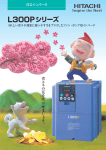
Hitachi’s L300P Series Variable Fre
Increased Energy Savings for Your
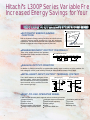
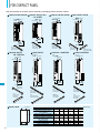
WIDE RANGE OF APPLICATION SPECIFIC FUNCTIONS
Example of Energy Savings (Fan)
With its Automatic Energy-saving Function, the L300P delivers
“real-time” energy-saving operation for your fan and pump
applications. The function insures that motor operates at minimum
current in response to the torque required by the load.
Operation by Inlet vane
and damper
Power Consumption
AUTOMATIC ENERGY-SAVING
FUNCTION
Operation by
v/f control
Amount of energy
to be saved
Operation by Automatic
Energy-saving Function
Frequency
ENHANCED INPUT/OUTPUT TERMINALS
Three relay output terminals are provided
as standard for flexible interface to external
control systems.
INTELLIGENT RELAY OUTPUTS
12C
12A 11C
NO contact X 2
11A AL0 AL1
AL2
NO-NC contact X 1
ANALOG OUTPUT MONITOR
In addition to PWM monitor(FM), programmable analog output monitors are also available for
both voltage(0-10VDC) and current(4-20mA) at AM and AMI terminals of the L300P.
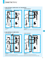
INTELLIGENT INPUT/ OUTPUT TERMINAL SYSTEM
The L300P features an intelligent control
terminal system, which allows necessary
drive I/O functions to be freely programmed.
Input terminals can be selected for either
sink or source type logic.
[Sink type logic]
Upper System
[Source type logic]
Upper System
+Power Supply
P24
FW
L300P
L300P
FW
CM1
EASY- TO-USE OPERATOR PANEL
L300P's digital operator panel supports various monitoring functions.
Output frequency
Output current
Rotation direction
Process variable, PID feedback
Intelligent input terminal status
1
Intelligent output terminal status
Scaled output frequency
Output voltage
Power
Cumulative RUN time
Cumulative power-on time
Trip event
Trip history
Warning code
quency Drive Delivers
Fan and Pump Applications!
CONTENTS
FOR OPTIMAL OPERATION
Highperformance
Easy
Maintenance
Global
Standards
Hitachi
Inverter
L300P
Ease of
Operation
Compact
Size
PAGE
FEATURES
1-4
STANDARD SPECIFICATIONS
5-7
DIMENSIONS
8 - 11
OPERATION and PROGRAMMING
12
FUNCTION LIST
13 - 16
TERMINALS
17 - 18
PROTECTIVE FUNCTIONS
19
CONNECTING DIAGRAM
20 - 21
CONNECTING TO PLC
22
WIRING and ACCESSORIES
23
ACCESSORIES
24 - 26
FOR COMPACT PANEL
27
TORQUE CHARACTERISTICS, DERATING DATA
28
FOR CORRECT OPERATION
29 - 30
ISO 14001
EC97J1095
ISO 9001
JQA-1153
Hitachi variable frequency
drives (inverters) in this
brochure are produced at the
factory registered under the
ISO 14001 standard for
environmental management
system and the ISO 9001
standard for inverter quality
management system.
2
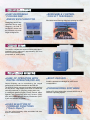
EASY-REMOVABLE
COOLING FAN
AND DC BUS CAPACITOR
Cooling fan(s) and DC bus
capaci-tors can be easily
changed in the field. A
fan ON/OFF function can
be activated to provide
longer cooling fan life.
REMOVABLE CONTROL
CIRCUIT TERMINALS
Eliminates control rewiring when field replacing the L300P.
Control Circuit Terminals
The L300P’s compact size helps economize panel space.
Installation area is reduced by approximately 30% from
that of our previous series.
(Comparison of 11kW (15HP))
EASE OF OPERATION WITH
DIGITAL OPERATOR (OPE-SR)
Output frequency can be controlled by the integral
potentiometer provided as standard on the OPE-SR.
The OPE-SR can be removed for remote control, and has
an easy-to-see 4-digit display and LEDs to indicate the
unit being monitored (i.e. frequency, amps, power, etc.).
A multilingual operator (English, French, German, Italian,
Spanish, and Portuguese) with copy function (SRW0EX) and a digital operator without potentiometer (OPES) are also available as options.
USER SELECTION OF
COMMAND FUNCTIONS
(“Quick Menu”)
You can select frequently used commands and store
them for fast reference.
3
BUILT-IN RS485
RS485 is provided as standard for ASCII serial
communication.
PROGRAMMING SOFTWARE
Optional PC drive configuration software which runs on
Windows® Operating System.
EMI FILTER
EMI filters to meet European EMC (EN61800-3, EN55011)
and low-voltage directive (EN50178) are available for system
conformance.
REDUCED NOISE FROM MAIN
CIRCUIT POWER SUPPLY AND
CONTROL CIRCUIT POWER SUPPLY
Disturbance voltage of the main circuit power supply and
of the control circuit power supply has been improved by
approximately 15dB( V) and 20dB( V) respectively compared
to our previous model(J300), resulting in significant reductions
to noise interference with sensors and other peripheral
devices.
Disturbance voltage of the main circuit power supply
(It does not comply with European EMC directive. To meet the EMC directive,
please use an EMI filter.)
Disturbance voltage [dB(µV)]
100
90
60
CONFORMITY TO GLOBAL
STANDARDS
CE, UL, c-UL, C-Tick approvals.
NETWORK COMPATIBILITY
The L300P can communicate with DeviceNet™,
PROFIBUS®, LONWORKS®, Modbus® RTU*1,
and Ethernet™*2 with communication options.
L300P - 015 L F U 2
J300-220LFU
L300P-220LFU2
40
Series Name
L300P series
.2
.3
.5 .7
1
5
Frequency(MHz)
7 10
20
Version number
Applicable Motor Capacity
30
Power Source
L :3-phase 200V Class
H:3-phase 400V Class
Disturbance voltage of the control circuit power supply
(Disturbance voltage of terminal L or CM1)
Disturbance voltage [dB(µV)]
75kW models to meet NEMA 1 rating.
MODEL NAME INDICATION
70
0
*NEMA 1 applies up to 30kW. An optional wire-entry conduit box is required for 37kW to
*1, *2: Being planned
J300 series
80
Standard enclosure protection for the L300P is IP20 (NEMA1*).
For IP54 (NEMA12), please contact Hitachi sales office.
J300 series
100
F:With Digital Operator
U:UL version for North America
E :CE version for Europe
80
60
40
20
0
MODEL CONFIGURATION
L300P series
J300-055LFU
L300P-055LFU2
.2
.3
.5
.7
1
3
Frequency(MHz)
Applicable Motor Capacity
in kW (HP)
5
7
10
20
30
HARMONICS MITIGATION
Terminals for the connection of a DC Reactor are provided as standard for harmonics suppression.
CONTROL OF VOLTAGE OF
MICRO SERGE
Suppressing the motor terminal voltage less than 2xE [V]
by improving the control method of PWM output.
Input voltage:400VAC(In the case)
Motor terminal voltage:1,131V(400VX√2X2)
IMPROVEMENT OF ENVIRONMENT
The printed circuit board inside an inverter is varnish
coating specification as standard.
3-phase 200V class
3-phase 400V class
1.5(2)
L300P-015LFU2
L300P-015HFU2/E2
2.2(3)
L300P-022LFU2
L300P-022HFU2/E2
3.7(5)
L300P-037LFU2
L300P-040HFU2/E2
5.5(7.5)
L300P-055LFU2
L300P-055HFU2/E2
7.5(10)
L300P-075LFU2
L300P-075HFU2/E2
11(15)
L300P-110LFU2
L300P-110HFU2/E2
15(20)
L300P-150LFU2
L300P-150HFU2/E2
18.5(25)
L300P-185LFU2
L300P-185HFU2/E2
22(30)
L300P-220LFU2
L300P-220HFU2/E2
30(40)
L300P-300LFU2
L300P-300HFU2/E2
37(50)
L300P-370LFU2
L300P-370HFU2/E2
45(60)
L300P-450LFU2
L300P-450HFU2/E2
55(75)
L300P-550LFU2
L300P-550HFU2/E2
75(100)
L300P-750LFU2
L300P-750HFU2/E2
90(125)
L300P-900HFU2/E2
110(150)
L300P-1100HFU2/E2
132(175)
L300P-1320HFU2/E2
Windows is a registered trademark of Microsoft Corp. in the U.S. and other countries.
DeviceNet is a trademark of Open DeviceNet Vendor Association.
PROFIBUS is a registered trademark of Profibus Nutzer Organization.
4
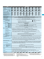
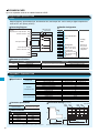
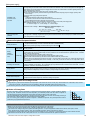
STANDARD SPECIFICATIONS
Item
UL version
Model
L300P-XXX
CE version
Enclosure (*2)
Applicable motor (4-pole, kW(HP)) (*3)
200V
Rated capacity
(kVA)
240V
Rated input voltage
Rated input current (A)
Required power supply capacity (kVA)
Rated output voltage (*4)
Rated output current (continuous)(A)
Control method
Output frequency range (*5)
Frequency accuracy
Frequency resolution
V/f characteristics
Overload capacity
Acceleration/deceleration time
Dynamic braking
(Short-time) (*6)
Braking
DC braking
Input
signal
Built-in BRD circuit(optional resistor)
RV(Reverse), CF1-CF4(Multispeed command), JG(Jogging), DB(External DC braking),
SET(Second motor constants setting), 2CH(Second accel./decel.), FRS(Free-run stop), EXT(External trip),
USP(Unattended start protection), CS(Change to/from commercial power supply),SFT(Software lock),
AT(Analog input selection), RS(Reset), STA(3-wire start), STP(3-wire stop), F/R(3-wire fwd./rev.), PID(PID On/Off),
PIDC(PID reset), UP/DWN(Remote-controlled accel./decel.) UDC(Remote-controlled data clearing),
SF1-SF7(Multispeed bit command 1-7), OLR(Overload limit change), ROK(RUN Permissive) and NO(Not selected)
One terminal(PTC)
Thermistor input
Intelligent output
terminals
Intelligent monitor
output terminals
Display monitor
Other user-settable parameters
Carrier frequency range
Protective functions
Environmental
conditions
Assign three functions to two NO contacts and one NO-NC combined contact
(RUN, FA1, FA2, OL, OD, AL, FA3, IP, UV, RNT, ONT RMD and THM)
Analog voltage, analog current, PWM output
Output frequency, output current, scaled value of output frequency, trip history, I/O terminal condition, input power, output voltage
V/f free-setting (up to 7 points), frequency upper/lower limit, frequency jump, accel./decel. curve selection, manual
torque boost value and frequency adjustment, analog meter tuning, starting frequency, carrier frequency, electronic thermal protection level, external frequency output zero/span reference, external frequency input bias start/end, analog input
selection, retry after trip, reduced voltage soft start, overload restriction, automatic energy-saving
0.5-12kHz
Over-current protection, overload protection, braking resistor overload protection, over-voltage protection, EEPROM
error, under-voltage error, CT(Current transformer) error, CPU error, external trip, USP error, ground fault, input overvoltage protection, instantaneous power failure, option 1 connection error, option 2 connection error, inverter thermal
trip, phase failure detection, IGBT error, thermistor error
Ambient operating /storage
temperature(*7)/humidity
Vibration (*8)
Location
–10-40°C(*9) / –20-65°C / 25-90%RH (No condensation)
5.9m/s (0.6G), 10-55Hz
2.9m/s (0.3G), 10-55Hz
Altitude 1,000m or less, indoors (no corrosive gases or dust)
Blue
Gray (Bezel for digital operator is blue)
2
Color
2
Options
EMI filters, input/output reactors, DC reactors, radio noise filters, braking resistors, braking units, LCR filter, communication cables, Network interface cards
Operator
OPE-SR(4-digit LED with potentiometer) / OPE-SRE(4-digit LED with potentiometer, English overlay)
Optional: OPE-S(4-digit LED), SRW-0EX(Multilingual (English,French, German, Italian, Spanish, and Portuguese)
operator with copy function), ICS-1,3(Cable for operators(1m, 3m))
Weight kg (lbs.)
3.5 (7.7) 3.5 (7.7) 3.5 (7.7) 3.5 (7.7)
*1: Up to 30kW.
An optional conduit box is required for 37kW to 55kW to meet NEMA 1 .
The protection method conforms to JEM 1030 / NEMA(U.S.).
*2:
*3: The applicable motor refers to Hitachi standard 3-phase motor (4-pole).
To use other motors, care must be taken to prevent the rated motor current
(50Hz) from exceeding the rated output current of the inverter.
5
External dynamic braking unit (option)
Performs at start; under set frequency at deceleration, or via an external input
(braking force, time, and operating frequency).
Up and Down keys
Potentiometer
DC 0-10V, –10-+10V (input impedance 10k ), 4-20mA (input impedance 100 )
RS-485 interface
Run key/Stop key (FW/RV can be set by function command.)
FW RUN/STOP (NO contact), RV set by terminal assignment (NO/NC selection), 3-wire input available
Set by RS-485
Operator
Frequency Potentiometer
setting
External signal
External port
Forward/ Operator
External signal
reverse
Start/stop External port
Intelligent
input terminals
(Assign five functions
to terminals)
Output
signal
200V Class
015LFU2 022LFU2 037LFU2 055LFU2 075LFU2 110LFU2 150LFU2 185LFU2 220LFU2 300LFU2 370LFU2 450LFU2 550LFU2 750LFU2
—
—
—
—
—
—
—
—
—
—
—
—
—
—
IP20 (NEMA 1) (*1)
55(75) 75(100)
45(60)
37(50)
30(40)
15(20) 18.5(25) 22(30)
11(15)
5.5(7.5) 7.5(10)
3.7(5)
2.2(3)
1.5(2)
93.5
72.7
58.5
48.4
39.1
29.4
25.2
20.0
15.2
11
8.3
5.7
3.6
2.5
112.2
87.2
70.2
58.1
46.9
35.3
30.3
24.1
18.2
13.3
9.9
6.8
4.3
3.1
3-phase (3-wire) 200-240V (± 10%), 50/60Hz
297
231
186
154
124
94
80
64
48
35
26
18
12
8.3
150
110
90
74
60
44
37
30
22
15
11
7.4
4.4
3
3-phase (3-wire) 200-240V (Corresponding to input voltage)
270
210
169
140
113
85
73
58
44
32
24
16.5
10.5
7.5
Line to line sine wave PWM
0.1-400Hz
Digital: ± 0.01% of the maximum frequency, Analog: ± 0.2%(25± 10°C)
Digital setting: 0.01Hz, Analog setting: (Maximum frequency)/4,000 (O terminal: 12-bit 0 –10V, O2 terminal: 12-bit-10–+10V)
V/f optionally variable, V/f control (Constant torque, reduced torque)
120% for 60sec., 150% for 0.5sec.
0.01-3,600sec. (Linear/curve, accel./decel. selection), Two-stage accel./decel.
5 (11)
5 (11)
5 (11)
12 (26.4) 12 (26.4) 12 (26.4)
*4: The output voltage decreases as the main power supply voltage decreases
except for the use of AVR function.
*5: To operate the motor beyond 50/60Hz, please consult with the motor
manufacturer about the maximum allowable rotation speed.
*6: Braking resistor is not integrated in the inverter. Please install optional
braking resistor or dynamic braking unit when large braking torque is
required.
20 (44)
30 (66)
30 (66)
50 (110)
Storage temperature refers to the temperature in transportation.
*7:
Conforms to the test method specified in JIS C0040(1999).
*8:
*9: When using the inverter from 40º to 50ºC ambient, the output current of
the inverter must be derated (see the next section on derating curves).
Item
UL version
Model
L300P-XXX
CE version
Enclosure (*2)
Applicable motor (4-pole, kW(HP)) (*3)
400V
Rated capacity
(kVA)
480V
Rated input voltage
Rated input current (A)
Required power supply capacity (kVA)
Rated output voltage (*4)
Rated output current (continuous)(A)
Control method
Output frequency range (*5)
Frequency accuracy
Frequency resolution
V/f characteristics
Overload capacity
Acceleration/deceleration time
Dynamic braking
(Short-time) (*6)
Braking
DC braking
Input
signal
1.5(2)
2.6
3.1
4.2
3
3.8
075HFU2 110HFU2 150HFU2 185HFU2 220HFU2 300HFU2
300HFE2
220HFE2
110HFE2
150HFE2 185HFE2
075HFE2
IP20 (NEMA 1) (*1)
30(40)
22(30)
18.5(25)
11(15)
15(20)
7.5(10)
5.5(7.5)
4.0(5)
2.2(3)
39.4
29.7
25.6
15.2
20.0
11
8.3
5.9
3.6
47.3
35.7
30.7
18.2
24.1
13.3
9.9
7.1
4.4
3-phase (3-wire) 380-480V (± 10%), 50/60Hz
63
47
41
24
32
18
13
9.5
5.8
60
44
37
22
30
15
11
8
4.4
3-phase (3-wire) 380-480V (Corresponding to input voltage)
57
43
37
22
29
16
12
8.6
5.3
Line to line sine wave PWM
0.1-400Hz
Digital: ± 0.01% of the maximum frequency, Analog: ± 0.2%(25± 10°C)
Digital setting: 0.01Hz, Analog setting: (Maximum frequency)/4,000 (O terminal: 12-bit 0 –10V, O2 terminal: 12-bit-10–+10V)
V/f optionally variable, V/f control (Constant torque, reduced torque)
120% for 60sec., 150% for 0.5sec.
0.01-3,600sec. (Linear/curve, accel./decel. selection), Two-stage accel./decel.
External dynamic braking unit
Built-in BRD circuit(optional resistor)
(option)
022HFU2
022HFE2
RV(Reverse), CF1-CF4(Multispeed command), JG(Jogging), DB(External DC braking),
SET(Second motor constants setting), 2CH(Second accel./decel.), FRS(Free-run stop), EXT(External trip),
USP(Unattended start protection), CS(Change to/from commercial power supply),SFT(Software lock),
AT(Analog input selection), RS(Reset), STA(3-wire start), STP(3-wire stop), F/R(3-wire fwd./rev.), PID(PID On/Off),
PIDC(PID reset), UP/DWN(Remote-controlled accel./decel.) UDC(Remote-controlled data clearing),
SF1-SF7(Multispeed bit command 1-7), OLR(Overload limit change), ROK(RUN Permissive) and NO(Not selected)
One terminal(PTC)
Thermistor input
Intelligent output
terminals
Intelligent monitor
output terminals
Display monitor
Other user-settable parameters
Carrier frequency range
Protective functions
Environmental
conditions
055HFU2
055HFE2
040HFU2
040HFE2
Performs at start; under set frequency at deceleration, or via an external input
(braking force, time, and operating frequency).
Up and Down keys
Potentiometer
DC 0-10V, –10-+10V (input impedance 10k ), 4-20mA (input impedance 100 )
RS-485 interface
Run key/Stop key (FW/RV can be set by function command.)
FW RUN/STOP (NO contact), RV set by terminal assignment (NO/NC selection), 3-wire input available
Set by RS-485
Operator
Frequency Potentiometer
setting
External signal
External port
Forward/ Operator
External signal
reverse
Start/stop External port
Intelligent
input terminals
(Assign five functions
to terminals)
Output
signal
400V Class
015HFU2
015HFE2
Assign three functions to two NO contacts and one NO-NC combined contact
(RUN, FA1, FA2, OL, OD, AL, FA3, IP, UV, RNT, ONT RMD and THM)
Analog voltage, analog current, PWM output
Output frequency, output current, scaled value of output frequency, trip history, I/O terminal condition, input power, output voltage
V/f free-setting (up to 7 points), frequency upper/lower limit, frequency jump, accel./decel. curve selection, manual
torque boost value and frequency adjustment, analog meter tuning, starting frequency, carrier frequency, electronic thermal protection level, external frequency output zero/span reference, external frequency input bias start/end, analog input
selection, retry after trip, reduced voltage soft start, overload restriction, automatic energy-saving
0.5-12kHz
Over-current protection, overload protection, braking resistor overload protection, over-voltage protection, EEPROM
error, under-voltage error, CT(Current transformer) error, CPU error, external trip, USP error, ground fault, input overvoltage protection, instantaneous power failure, option 1 connection error, option 2 connection error, inverter thermal
trip, phase failure detection, IGBT error, thermistor error
Ambient operating /storage
temperature(*7)/humidity
Vibration (*8)
Location
–10-40°C(*9) / –20-65°C / 25-90%RH (No condensation)
5.9m/s (0.6G), 10-55Hz
Altitude 1,000m or less, indoors (no corrosive gases or dust)
Blue
2
Color
Options
EMI filters, input/output reactors, DC reactors, radio noise filters, braking resistors, braking units, LCR filter, communication cables, Network interface cards
Operator
OPE-SR(4-digit LED with potentiometer) / OPE-SRE(4-digit LED with potentiometer, English overlay)
Optional: OPE-S(4-digit LED), SRW-0EX(Multilingual (English,French, German, Italian, Spanish, and Portuguese)
operator with copy function), ICS-1,3(Cable for operators(1m, 3m))
Weight kg (lbs.)
3.5 (7.7)
3.5 (7.7)
*1: Up to 30kW.
An optional conduit box is required for 37kW to 55kW to meet NEMA 1 .
The protection method conforms to JEM 1030 / NEMA(U.S.).
*2:
*3: The applicable motor refers to Hitachi standard 3-phase motor (4-pole).
To use other motors, care must be taken to prevent the rated motor current
(50Hz) from exceeding the rated output current of the inverter.
3.5 (7.7)
3.5 (7.7)
5 (11)
5 (11)
*4: The output voltage decreases as the main power supply voltage decreases
except for the use of AVR function.
*5: To operate the motor beyond 50/60Hz, please consult with the motor
manufacturer about the maximum allowable rotation speed.
*6: Braking resistor is not integrated in the inverter. Please install optional
braking resistor or dynamic braking unit when large braking torque is
required.
5 (11)
12 (26.4)
12 (26.4)
12 (26.4)
*7: Storage temperature refers to the temperature in transportation.
Conforms to the test method specified in JIS C0040(1999).
*8:
*9: When using the inverter from 40º to 50ºC ambient, the output current of
the inverter must be derated (see the next section on derating curves).
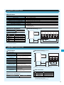
6
STANDARD SPECIFICATIONS
Item
UL version
Model
L300P-XXX
CE version
Enclosure (*2)
Applicable motor (4-pole, kW(HP)) (*3)
400V
Rated capacity
(kVA)
480V
Rated input voltage
Rated input current (A)
Required power supply capacity (kVA)
Rated output voltage (*4)
Rated output current (continuous)(A)
Control method
Output frequency range (*5)
Frequency accuracy
Frequency resolution
V/f characteristics
Overload capacity
Acceleration/deceleration time
Dynamic braking
(Short-time) (*6)
Braking
DC braking
Input
signal
External dynamic braking unit (option)
Performs at start; under set frequency at deceleration, or via an external input
(braking force, time, and operating frequency).
Up and Down keys
Potentiometer
DC 0-10V, –10-+10V (input impedance 10k ), 4-20mA (input impedance 100 )
RS-485 interface
Run key/Stop key (FW/RV can be set by function command.)
FW RUN/STOP (NO contact), RV set by terminal assignment (NO/NC selection), 3-wire input available
Set by RS-485
Operator
Frequency Potentiometer
setting
External signal
External port
Forward/ Operator
External signal
reverse
Start/stop External port
Intelligent
input terminals
(Assign five functions
to terminals)
Output
signal
400V Class
900HFU2
1100HFU2
1320HFU2
450HFU2
550HFU2
750HFU2
900HFE2
1100HFE2
1320HFE2
450HFE2
550HFE2
750HFE2
IP20 (NEMA 1) (*1)
IP00
90 (125)
110 (150)
132 (175)
37(50)
45(60)
55(75)
75(100)
110.8
135.0
159.3
48.4
58.8
72.7
93.5
133.0
162.1
191.2
58.1
70.1
87.2
112.2
3-phase (3-wire) 380-480V (± 10%), 50/60Hz
176
215
253
77
94
116
149
180
220
264
74
90
110
150
3-phase (3-wire) 380-480V (Corresponding to input voltage)
160
195
230
70
85
105
135
Line to line sine wave PWM
0.1-400Hz
Digital: ± 0.01% of the maximum frequency, Analog: ± 0.2%(25± 10°C)
Digital setting: 0.01Hz, Analog setting: (Maximum frequency)/4,000 (O terminal: 12-bit 0 –10V, O2 terminal: 12-bit-10–+10V)
V/f optionally variable, V/f control (Constant torque, reduced torque)
120% for 60sec., 150% for 0.5sec.
0.01-3,600sec. (Linear/curve, accel./decel. selection), Two-stage accel./decel.
370HFU2
370HFE2
RV(Reverse), CF1-CF4(Multispeed command), JG(Jogging), DB(External DC braking),
SET(Second motor constants setting), 2CH(Second accel./decel.), FRS(Free-run stop), EXT(External trip),
USP(Unattended start protection), CS(Change to/from commercial power supply),SFT(Software lock),
AT(Analog input selection), RS(Reset), STA(3-wire start), STP(3-wire stop), F/R(3-wire fwd./rev.), PID(PID On/Off),
PIDC(PID reset), UP/DWN(Remote-controlled accel./decel.) UDC(Remote-controlled data clearing),
SF1-SF7(Multispeed bit command 1-7), OLR(Overload limit change), ROK(RUN Permission) and NO(Not selected)
One terminal(PTC)
Thermistor input
Intelligent output
terminals
Intelligent monitor
output terminals
Display monitor
Other user-settable parameters
Carrier frequency range
Protective functions
Environmental
conditions
Assign three functions to two NO contacts and one NO-NC combined contact
(RUN, FA1, FA2, OL, OD, AL, FA3, IP, UV, RNT, ONT, RMD and THM)
Analog voltage, analog current, PWM output
Output frequency, output current, scaled value of output frequency, trip history, I/O terminal condition, input power, output voltage
V/f free-setting (up to 7 points), frequency upper/lower limit, frequency jump, accel./decel. curve selection, manual
torque boost value and frequency adjustment, analog meter tuning, starting frequency, carrier frequency, electronic thermal protection level, external frequency output zero/span reference, external frequency input bias start/end, analog input
selection, retry after trip, reduced voltage soft start, overload restriction, automatic energy-saving
0.5-12kHz
0.5-8kHz
Over-current protection, overload protection, braking resistor overload protection, over-voltage protection, EEPROM
error, under-voltage error, CT(Current transformer) error, CPU error, external trip, USP error, ground fault, input overvoltage protection, instantaneous power failure, option 1 connection error, option 2 connection error, inverter thermal
trip, phase failure detection, IGBT error, thermistor error
Ambient operating /storage
temperature(*7)/humidity
Vibration (*8)
Location
–10-40°C(*9) / –20-65°C / 25-90%RH (No condensation)
2.9m/s (0.3G), 10-55Hz
Altitude 1,000m or less, indoors (no corrosive gases or dust)
Gray (Bezel for digital operator is blue)
2
Color
EMI filters, input/output reactors, DC reactors, radio noise filters, braking resistors,
braking units, LCR filter, communication cables, Network interface cards
Options
Operator
Weight kg (lbs.)
OPE-SR(4-digit LED with potentiometer) / OPE-SRE(4-digit LED with potentiometer, English overlay)
Optional: OPE-S(4-digit LED), SRW-0EX(Multilingual (English,French, German, Italian, Spanish, and Portuguese)
operator with copy function), ICS-1,3(Cable for operators(1m, 3m))
20 (44)
*1: Up to 30kW.
An optional conduit box is required for 37kW to 55kW to meet NEMA 1 .
The protection method conforms to JEM 1030 / NEMA(U.S.).
*2:
*3: The applicable motor refers to Hitachi standard 3-phase motor (4-pole).
To use other motors, care must be taken to prevent the rated motor current
(50Hz) from exceeding the rated output current of the inverter.
7
30 (66)
30 (66)
30 (66)
*4: The output voltage decreases as the main power supply voltage decreases
except for the use of AVR function.
*5: To operate the motor beyond 50/60Hz, please consult with the motor
manufacturer about the maximum allowable rotation speed.
*6: Braking resistor is not integrated in the inverter. Please install optional
braking resistor or dynamic braking unit when large braking torque is
required.
60 (132)
60 (132)
80 (176)
Storage temperature refers to the temperature in transportation.
*7:
Conforms to the test method specified in JIS C0040(1999).
*8:
*9: When using the inverter from 40º to 50ºC ambient, the output current of
the inverter must be derated (see the next section on derating curves).
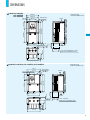
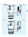
DIMENSIONS
L300P-015-055LFU2
015-055HFU2
015-055HFE2
150(5.91)
[Unit:mm (inch)]
Inches for reference only
130(5.12)
25(0.98)
Digital Operator
80(3.15)
Exhaust
8.5(0.33)
130(5.12)
Wall
3- 20( 0.78)
Wiring Hole
40(1.57)
241(9.49)
164(6.46)
6(0.24)
255(10.04)
79(3.11)
2- 6 ( 0.24)
Air intake
143(5.63)
140(5.51)
LFU2、HFU2 type(055LFU2、HFU2)
Conduit box to meet NEMA1 rating
7(0.28)
69(2.72)
75(2.95)
[Unit:mm (inch)]
Inches for reference only
L300P-075-150LFU2, 075-150HFE2, 075-150HFU2
Digital Operator
2- 7( 0.28)
Exhaust
260(10.24)
Wall
7(0.28)
170(6.69)
82(3.23)
7(0.28)
8.5(0.33)
189(7.44)
70(2.76)
170(6.69)
246(9.69)
79(3.11)
24.5(0.97)
210(8.27)
189(7.44)
80(3.15)
3- 25( 0.98)
Wiring hole
Air intake
80(3.15)
LFU2、HFU2 type
Conduit box to meet NEMA1 rating
203(7.99)
8
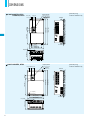
DIMENSIONS
L300P-185-300LFU2,
185-300HFE2,
185-300HFU2
[Unit:mm (inch)]
Inches for reference only
Digital Operator
250(9.84)
2- 7( 0.28)
Exhaust
390(15.35)
Wall
9.5(0.37)
83(3.27)
229(9.02)
147(5.79)
7(0.28)
190(7.48)
8.5(0.33)
273(10.75)
376(14.80)
79(3.11)
24.5(0.97)
229(9.02)
80(3.15)
Air intake
4- 29.5( 1.16) 104(4.09)
Wiring hole
LFU2、HFU2 type
Conduit box to meet NEMA1 rating
244(9.61)
L300P-370LFU2,
370HFE2,
370HFU2
45(1.77) 80(3.15)
Exhaust
Wall
2-10 (0.39)
175(6.89)
145(5.71)
271(10.67)
510 (20.08)
540 (21.26)
2- 10 ( 0.39 )
79(3.11)
[Unit:mm (inch)]
Inches for reference only
Digital Operator
Air intake
8.5(0.33)
265 (10.43)
195 (7.68)
310 (12.20)
9
74(2.91)
Conduit box to meet NEMA1 rating (Optional)
80(3.15)
Digital Operator
[Unit:mm (inch)]
Inches for reference only
Exhaust
520(20.47)
550(21.65)
2- 12( 0.47)
79(3.11)
L300P-450-550LFU2,
450-750HFE2, 32.5(1.28)
450-750HFU2
2-12 (0.47)
185(7.28)
155(6.01)
277(10.91)
Wall
Air intake
8.5(0.33)
300 (11.81)
390 (15.35)
90(3.54)
250 (9.84)
Conduit box to meet NEMA1 rating (Optional)
L300P-750LFU2
[Unit:mm (inch)]
Inches for reference only
Digital Operator
12(0.47 )
Exhaust
700(27.56)
2
Wall
2-12 (0.47)
380(14.96)
190(7.48)
160(6.30)
352(13.87)
670(26.38)
79(3.11)
125(4.92) 80(3.15)
Air intake
480(18.90)
250 (9.84)
8.5(0.33)
104(4.09)
Conduit box to meet NEMA 1 rating
(Optional)
10
DIMENSIONS
L300P-900HFE2, HFU2
-1100HFE2, HFU2
32.5(1.28)
80(3.15)
[Unit:mm (inch)]
Inches for reference only
Digital Operator
2- 12( 0.47)
700(27.56)
Wall
357(14.06)
670(26.38)
79(3.11)
Exhaust
Air intake
2-12(0.47)
300(11.81)
390(15.35)
270(10.63)
8.5(0.33)
L300P-1320HFE2, HFU2
[Unit:mm (inch)]
Inches for reference only
Digital Operator
62.5(2.46) 80(3.15)
2
12(0.47 )
740 (29.13)
480(18.91)
710 (27.95)
79(3.11)
Exhaust
Wall
2-12 (0.47)
380 (14.76)
480 (18.90)
270 (10.63)
8.5 (0.33)
11
Air intake
OPERATION and PROGRAMMING
L300P Series can be easily operated with the digital operator (OPE-SR) provided as standard. The Digital operator can
also be detached and used for remote-control. A multilingual (English, French, German Italian, Spanish, and Portuguese)
operator with copy function (SRW-0EX) or a digital operator without potentiometer(OPE-S) is also available as an option.
(For US version, OPE-SRE (English overlay with potentiometer) is provided as standard.)
Parameter Display
Power LED
Lights when the power input to
the drive is ON.
Displays frequency, motor current, rotational speed of the
motor, and an alarm code.
Display Unit LEDs
Monitor LEDs
Indicates the unit associated
with the parameter display.
Shows drive's status.
RUN Key
Potentiometer
Press to run the motor.
STOP/RESET Key
Store Key
Press to stop the drive or
reset an alarm.
Press to write the new value to
the EEPROM.
Function Key
Up/Down Keys
Press up or down to sequence through
parameters and functions shown on the
display, and increment/decrement values.
Press to set or monitor a
parameter value.
1. Setting the maximum output frequency
(1)
(4)
or the value previously
monitored is displayed.
(2)Function code appears.
POWER
Power
on
V
kW
A
A
PRG
%
MIN
(5)
MAX
Press
FUNC
key.
MIN
POWER
V
kW
A
A
PRG
%
MIN
MIN
MAX
Press
FUNC
key.
MIN
Press
FUNC
key.
V
A
(8)Returns to
and
the setting is complete.
POWER
ALARM
Hz
RUN
Press
to set desired value.
MIN
MAX
STR
FUNC
Press STR key
to store the value.
(2)The motor runs at the frequency
set by the potentiometer.
POWER
POWER
ALARM
ALARM
Hz
Power
on
A
MIN
V
A
PRG
(3)The motor stops.
POWER
ALARM
Hz
RUN
V
kW
A
PRG
%
Press RUN key and turn the
potentiometer clockwise.
MAX
STR
MAX
STR
Hz
RUN
kW
%
FUNC
MIN
FUNC
*To run the motor, go
back to monitor mode
or basic setting mode.
or the value previously
monitored is displayed.
V
kW
%
2. Running the motor(by potentiometer)
RUN
A
PRG
appears.
PRG
V
kW
%
MAX
MAX
STR
Hz
until
(1)
MIN
FUNC
ALARM
PRG
STR
FUNC
MAX
POWER
RUN
kW
kW
%
(7)Newly set value is displayed.
%
STR
A
PRG
STR
FUNC
appears.
Hz
RUN
V
FUNC
Press
until
ALARM
Hz
Press
MAX
POWER
ALARM
RUN
PRG
V
kW
A
%
(6)Preset value is displayed.
appears.
Hz
RUN
V
PRG
STR
FUNC
ALARM
Hz
RUN
kW
%
STR
FUNC
POWER
ALARM
Hz
RUN
V
or the code
number set in the end of
last setting is displayed.
POWER
ALARM
Hz
PRG
appears.
POWER
ALARM
RUN
(3)
MIN
FUNC
kW
%
Press
MAX
STOP
RESET
key to stop the motor.
MIN
STR
MAX
STR
FUNC
(Output frequency monitor)
3. Monitoring output current value
(1)
or the value previously
monitored is displayed.
(2)Function code appears.
POWER
Power
on
V
A
PRG
V
A
PRG
MIN
MAX
Press
FUNC
key.
MIN
FUNC
ALARM
Hz
RUN
V
kW
A
PRG
%
STR
POWER
ALARM
Hz
RUN
kW
%
FUNC
POWER
ALARM
Hz
(4)Output current value
is displayed.
appears.
POWER
ALARM
RUN
(3)
Hz
RUN
V
kW
A
PRG
%
MAX
STR
Press
until
MIN
appears.
FUNC
kW
%
MAX
STR
Press
FUNC
key.
MIN
FUNC
MAX
STR
12
FUNCTION LIST
[
Monitoring Functions and Main Profile Parameters
Code
Name
Description
]
= Allowed
= Not permitted
Default Setting Run-time Run-time Data Edit
-FE(CE) -FU2(UL) Setting (Enabled at b031)
d001
Output frequency monitor
0.00-99.99/100.0-400.0Hz
–
–
–
–
d002
Output current monitor
0.0-999.9A
–
–
–
–
d003
Motor rotational direction monitor
F(Forward) / o(Stop) / r(Reverse)
–
–
–
–
d004
Process variable (PV), PID feedback monitor
0.00-99.99/100.0-999.9/1000.-9999./1000-9999/ 100- 999(10,000-99,900)
–
–
–
–
FW
d005
Intelligent input terminal status
Monitor Mode
54
d006
32
Intelligent output terminal status
AL
12
ON
OFF
(Example) Terminal FW, 2 and 1 : ON
Terminal 5, 4, and 3 : OFF
–
–
–
–
ON
OFF
(Example) Terminal 12 and 11 : ON
AL :OFF
–
–
–
–
–
1
11
d007
Scaled output frequency monitor
0.00-99.99/100.0-999.9/1000.-9999./1000-3996(10,000-39,960)
–
–
–
d013
Output voltage monitor
0.0-600.0V
–
–
–
–
d014
Power monitor
0.0-999.9kW
–
–
–
–
d016
Cumulative RUN time monitor
0.-9999./1000-9999/ 100- 999 (10,000-99,900)hr
–
–
–
–
d017
Cumulative power-on time monitor
0.-9999./1000-9999/ 100- 999 (10,000-99,900)hr
–
–
–
–
d080
Trip count monitor
0.-9999./1000-6553(10,000-65,530)
–
–
–
–
d081
Trip monitor 1-6
Displays trip event information
–
–
–
–
–
–
–
–
Expanded Function
Setting Mode
d086
d090
Warning monitor
Warning code
F001
Output frequency setting
0.0, Starting frequency to maximum frequency / maximum frequency for second motor
0.00Hz 0.00Hz
F002
Acceleration time (1) setting
0.01-99.99/100.0-999.9/1000.-3600. sec.
30.00s
60.00s
F202
Acceleration time (1) setting for second motor
0.01-99.99/100.0-999.9/1000.-3600. sec.
30.00s
60.00s
F003
Deceleration time (1) setting
0.01-99.99/100.0-999.9/1000.-3600. sec.
30.00s
60.00s
F203
Deceleration time (1) setting for second motor
0.01-99.99/100.0-999.9/1000.-3600. sec.
30.00s
60.00s
F004
Motor rotational direction setting
00(Forward) / 01 (Reverse)
00
00
A---
A Group: Standard functions
b---
b Group: Fine tuning functions
C---
C Group: Intelligent terminal functions
H---
H Group: Motor constants functions
P---
P Group: Expansion card functions
U---
U Group: User-selectable menu functions
[
A Group: Standard Functions
Name
Multispeed and Jogging Frequency Setting
Analog Input Setting
Basic Setting
Code
13
A001
A002
A003
A203
A004
A204
A005
A006
A011
A012
A013
A014
A015
A016
A019
A020
A220
Description
Frequency source setting
00(Potentiometer) / 01(Terminals) / 02(Operator) / 03(RS485) / 04 (Expansion card 1) / 05(Expansion card 2)
Run command source setting
01(Terminals) / 02(Operator) / 03(RS485) / 04 (Expansion card 1) / 05(Expansion card 2)
Base frequency setting
30.00Hz-Maximum frequency
Base frequency setting for second motor
30.00Hz-Maximum frequency for second motor
Maximum frequency setting
30.00-400.0Hz
Maximum frequency setting for second setting
30.00-400.0Hz
AT selection
00(Selection between O and OI at AT) / 01(Selection between O and O2 at AT)
O2 selection
00(Independent) / 01(Only positive) / 02(Both positive and negative)
O-L input active range start frequency
0.00-400.0Hz
O-L input active range end frequency
0.00-400.0Hz
O-L input active range start voltage
0.-100.%
O-L input active range end voltage
0.-100.%
O-L input start frequency enable
00(External frequency output zero reference) / 01(0Hz)
External frequency filter time constant
1.-30. (Sampling time = 2 msec.)
Multispeed operation selection
00(Binary: up to 16-stage speed at 4 terminals) / 01(Bit: up to 6-stage speed at 5 terminals)
Multispeed frequency setting (0)
0.00, Starting frequency to maximum frequency
Multispeed frequency setting (0) for second motor 0.00, Starting frequency to maximum frequency for second motor
Default Setting
Run-time Run-time Data Edit
-FE(CE) -FU2(UL) Setting (Enabled at b031)
01
01
01
01
60.
50.
60.
50.
60.
50.
60.
50.
00
00
00
00
0.00
0.00
60.00
0.00
0.
0.
100.
100.
01
01
8.
8.
00
00
0.00
0.00
0.00
0.00
A021
I
A035
Multispeed frequency setting (1-15)
0.00, Starting frequency to maximum frequency
0.00
0.00
A038
Jog frequency setting
0.00, Starting frequency to 9.99Hz
1.00
1.00
Jog stop mode
00(Free-run stop/disable during RUN) / 01(Deceleration to stop/ disable during RUN) /
02(DC braking to stop/ disable during RUN) / 03(Free-run stop/ enable during RUN) /
04(Deceleration to stop/ enable during RUN) / 05(DC braking to stop/ enable during
RUN)
00
00
A039
]
= Allowed
= Not permitted
[
Name
Code
V/f
Characteristic
DC Braking
Upper/
Lower
Limit and
Jump
Frequency
PID Control
AVR
Function
Operation
Mode and
Accel./
Decel.
Function
External
Frequency
Tuning
Accel./
Decel.
Curve
A041
A241
A042
A242
A043
A243
A044
A244
A045
A051
A052
A053
A054
A055
A056
A057
A058
A059
A061
A261
A062
A262
A063
A064
A065
A066
A067
A068
A069
A070
A071
A072
A073
A074
A075
A076
A081
A082
A085
A086
A092
A292
A093
A293
A094
A294
A095
A295
A096
A296
A097
A098
A101
A102
A103
A104
A105
A111
A112
A113
A114
A131
A132
( 1) 90kW and over
*
Torque boost method selection
Torque boost method selection for second motor
Manual torque boost value
Manual torque boost value for second motor
Manual torque boost frequency adjustment
Manual torque boost frequency adjustment for second motor
V/f characteristic curve selection
V/f characteristic curve selection for second motor
V/f gain setting
DC braking enable
DC braking frequency setting
DC braking wait time
DC braking force setting
DC braking time setting
DC braking edge or level detection
DC braking force setting at the starting point
DC braking time setting at the starting point
DC braking carrier frequency setting
Frequency upper limit setting
Frequency upper limit setting for second motor
Frequency lower limit setting
Frequency lower limit setting for second motor
Jump frequency (1) setting
Jump frequency width (1) setting
Jump frequency (2) setting
Jump frequency width (2) setting
Jump frequency (3) setting
Jump frequency width (3) setting
Acceleration hold frequency setting
Acceleration stop time setting
PID function enable
PID proportional gain
PID integral gain
PID differential gain
Process variable scale conversion
Process variable source setting
AVR function selection
AVR voltage selection
Operation mode selection
Energy saving mode tuning
Acceleration time (2)
Acceleration time (2) for second motor
Deceleration time (2)
Deceleration time (2) for second motor
Select method to switch to second accel./ decel. profile
Select method to switch to second accel./ decel. profile for second motor
Accel(1) to Accel(2) frequency transition point
Accel(1) to Accel(2) frequency transition point for second motor
Decel(1) to Decel(2) frequency transition point
Decel(1) to Decel(2) frequency transition point for second motor
Acceleration curve selection
Deceleration curve selection
OI-L input active range start frequency
OI-L input active range end frequency
OI-L input active range start voltage
OI-L input active range end voltage
OI-L input start frequency enable
O2-L input active range start frequency
O2-L input active range end frequency
O2-L input active range start voltage
Description
Default Setting
-FE(CE)
00(Manual torque boost) / 01(Automatic torque boost)
00
00
1.0
0.0-20.0%
1.0
0.0-50.0%
5.0
0.0-50.0%
5.0
00(VC) / 01(VP 1.7th power) / 02(V/f free-setting)
00
00(VC) / 01(VP 1.7th power) / 02(V/f free-setting)
00
20.-100.
100.
00(Disabled) / 01(Enabled)
00
0.00-60.00Hz
0.50
0.0-5.0sec.
0.0
0.-70.%
0.
0.0-60.0sec.
0.0
00(Edge) / 01(Level)
01
0.-70.%
0.
0.0-60.0sec.
0.0
0.5-12kHz (To be derated) {0.5-8kHz}(*1)
3.0
0.00, Starting frequency to maximum frequency
0.00
0.00, Starting frequency to maximum frequency for second motor
0.00
0.00, Starting frequency to maximum frequency
0.00
0.00, Starting frequency to maximum frequency for second motor
0.00
0.00-99.99/100.0-400.0Hz
0.00
0.00-10.00Hz
0.50
0.00-99.99/100.0-400.0Hz
0.00
0.00-10.00Hz
0.50
0.00-99.99/100.0-400.0Hz
0.00
0.00-10.00Hz
0.50
0.00-99.99/100.0-400.0Hz
0.00
0.0-60.0sec.
0.0
00(Disable) / 01(Enable)
00
0.2-5.0
1.0
0.0-3600.0sec.
1.0
0.0-100.0sec.
0.0
0.01-99.99%
1.00
00(at OI) / 01(at O)
00
00(Always ON) / 01(Always OFF) / 02(OFF during deceleration)
00
200/215/220/230/240, 380/400/415/440/460/480V
230/400
00(Normal operation) / 01(Energy-saving operation)
00
0.0-100.0sec.
50.0
0.01-99.99/100.0-999.9/1000.-3600.sec.
15.00
0.01-99.99/100.0-999.9/1000.-3600.sec.
15.00
0.01-99.99/100.0-999.9/1000.-3600.sec.
15.00
0.01-99.99/100.0-999.9/1000.-3600.sec.
15.00
00(2CH input from terminal) / 01(Transition frequency)
00
00(2CH input from terminal) / 01(Transition frequency)
00
0.00-99.99/100.0-400.0Hz
0.00
0.00-99.99/100.0-400.0Hz
0.00
0.00-99.99/100.0-400.0Hz
0.00
0.00-99.99/100.0-400.0Hz
0.00
00(Linear)/ 01(S-curve)/ 02(U-shape)/ 03(Reverse U-shape)
00
00(Linear)/ 01(S-curve)/ 02(U-shape)/ 03(Reverse U-shape)
00
0.00-400.0Hz
0.00
0.00-400.0Hz
0.00
0.-100.%
20
0.-100.%
100
00(External frequency output zero reference) / 01(0Hz)
01
– 400.0-400.0Hz
0.00
– 400.0-400.0Hz
0.00
–100.-100.%
–100
00(Manual torque boost) / 01(Automatic torque boost)
0.0-20.0%
O2-L input active range end voltage
–100.-100.%
Acceleration curve constants setting
01(Smallest deviation)-10(Largest deviation)
Deceleration curve constants setting
01(Smallest deviation)-10(Largest deviation)
100
02
02
-FU2(UL)
]
= Allowed
= Not permitted
Run-time Run-time Data Edit
Setting (Enabled at b031)
00
00
1.0
1.0
5.0
5.0
01
01
100.
00
0.50
0.0
0.
0.0
01
0.
0.0
3.0
0.00
0.00
0.00
0.00
0.00
0.50
0.00
0.50
0.00
0.50
0.00
0.0
00
1.0
1.0
0.0
1.00
00
00
230/460
00
50.0
15.00
15.00
15.00
15.00
00
00
0.00
0.00
0.00
0.00
00
00
0.00
60.00
20
100
01
0.00
0.00
–100
100
02
02
14
[
B Group : Fine Tuning Functions
Name
Code
Selection of automatic restart mode
00(Alarm output after trip, automatic restart disable) / 01(Restart at 0Hz) / 02(Resume operation after frequency matching) / 03(Resume previous frequency after
frequency matching, then decelerate to stop and display trip information)
b004
b005
b006
b007
Allowable instantaneous power failure time
Time delay enforced before motor restart
Instantaneous power failure and under-voltage trip enable
Number of restarts after instantaneous power failure and under-voltage trip
Phase loss detection enable
Restart frequency setting
0.3-25.0sec.
0.3-100.0sec.
00(Disable) / 01(Enable) / 02(Disable during stop and ramp to stop)
00(16 times) / 01(Always restart)
00(Disable) / 01(Enable)
0.00-99.99/100.0-400.0Hz
b012
Level of electronic thermal setting
0.20*rated current-1.20*rated current
b212
Level of electronic thermal setting for second motor
0.20*rated current-1.20*rated current
b013
b213
b015
b016
b017
b018
b019
b020
Electronic thermal characteristics
Electronic thermal characteristics for second motor
Free-setting electronic thermal frequency (1)
Free-setting electronic thermal current (1)
Free-setting electronic thermal frequency (2)
Free-setting electronic thermal current (2)
Free-setting electronic thermal frequency (3)
Free-setting electronic thermal current (3)
00(Reduced torque) / 01(Constant torque) / 02(V/f free-setting)
00(Reduced torque) / 01(Constant torque) / 02(V/f free-setting)
0.-400.Hz
0.0-1000.A
0.-400.Hz
0.0-1000.A
0.-400.Hz
0.0-1000.A
b021
Overload restriction operation mode
00(Disable) / 01(Enable during accel./constant speed) /
02(Enable during constant speed)
b001
b002
Restart after
Instantaneous b003
Power Failure
Electronic
Thermal
b022
Overload restriction setting
0.50*rated current-1.50*rated current
Overload
b023
Restriction
Deceleration rate at overload restriction
0.10-30.00
b024
Overload restriction operation mode (2)
00(Disable) / 01(Enable during accel./ constant speed) /
02(Enable at constant speed)
b025
Overload restriction setting (2)
0.50*rated current-1.50*rated current
b026
Deceleration rate at overload restriction (2)
0.10-30.00
Software lock mode selection
00(All parameters except b031 are locked when SFT from terminal is
on) / 01(All parameters except b031 and output frequency F001 are
locked when SFT from terminal is on) / 02(All parameters except
b031 are locked) / 03(All parameters except b031 and output frequency F001 are locked) / 10(Run-time data edit mode)
Software
Lock
Others
b031
00
00
1.0
1.0
1.0
1.0
00
00
00
00
01
01
0.00
0.00
Rated Rated
current current
Rated Rated
current current
00
01
00
01
0.
0.
0.0
0.0
0.
0.
0.0
0.0
0.
0.
0.0
0.0
01
01
Rated Rated
current* current*
1.20
1.10
1.00
15.00
01
01
Rated Rated
current* current*
1.20
1.20
1.00
1.00
01
01
b034
RUN/ power-on warning time
0.–9999./1000–6553(10,000–65,5300)hr (Output to intelligent terminal)
0.
0.
Rotational direction restriction
00(Enable for both directions) / 01(Enable for forward) /
02(Enable for reverse)
00
00
b036
b037
b080
b081
b082
b083
Reduced voltage soft start selection
Function code display restriction
AM terminal analog meter adjustment
FM terminal analog meter adjustment
Start frequency adjustment
Carrier frequency setting
00(Short)-06(Long)
00(All) / 01(Utilized functions) / 02(User-selected functions only)
0-255
0-255
0.10-9.99Hz
0.5-12.0kHz (To be derated) {0.5-8kHz}(*1)
06
00
180
60
0.50
3.0
06
00
180
60
0.50
3.0
b084
Initialization mode
00(Trip history clear) / 01(Parameter initialization) / 02(Trip history
clear and parameter initialization)
00
00
Country code for initialization
Frequency scaling conversion factor
STOP key enable
Resume on free-run stop cancellation mode
Dynamic braking usage ratio
Stop mode selection
Cooling fan control
Dynamic braking control
Dynamic braking activation level
Thermistor for thermal protection control
Thermistor for thermal protection level setting
Free-setting V/f frequency (1)
Free-setting V/f voltage (1)
Free-setting V/f frequency (2)
Free-setting V/f voltage (2)
Free-setting V/f frequency (3)
Free-setting V/f voltage (3)
Free-setting V/f frequency (4)
Free-setting V/f voltage (4)
Free-setting V/f frequency (5)
Free-setting V/f voltage (5)
Free-setting V/f frequency (6)
Free-setting V/f voltage (6)
Free-setting V/f frequency (7)
Free-setting V/f voltage (7)
00(Japanese version) / 01(European version) / 02(North American version)
02
01
0.1-99.9
1.0
1.0
00(Enable) / 01(Disable)
00
00
00(Restart at 0Hz) / 01(Resume operation after frequency matching)
00
00
0.0-100.0%
0.0
0.0
00(Deceleration and stop) / 01(Free-run stop)
00
00
00(Fan is always ON) / 01(Fan is ON during RUN including 5min. afetr power-on and stop)
00
00
00(Disable) / 01(Enable during run) / 02(Enable during stop)
00
00
330-380/660-760V
360/720 360/720
00(Disable) / 01(PTC enable) / 02(NTC enable)
00
00
0.0-9999
3000
3000
0.-Free-setting V/f frequency (2)
0.0
0.0
0.0-800.0V
0.0
0.0
0.-Free-setting V/f frequency (3)
0.0
0.0
0.0-800.0V
0.0
0.0
0.-Free-setting V/f frequency (4)
0.0
0.0
0.0-800.0V
0.0
0.0
0.-Free-setting V/f frequency (5)
0.0
0.0
0.0-800.0V
0.0
0.0
0.-Free-setting V/f frequency (6)
0.0
0.0
0.0-800.0V
0.0
0.0
0.-Free-setting V/f frequency (7)
0.0
0.0
0.0-800.0V
0.0
0.0
0.-400.Hz
0.0
0.0
0.0-800.0V
0.0
0.0
( 1) 90kW and over
*
]
Run-time Run-time Data Edit
-FE(CE) -FU2(UL) Setting (Enabled at b031)
b035
b085
b086
b087
b088
b090
b091
b092
b095
b096
b098
b099
b100
b101
b102
b103
b104
b105
Free-setting b106
V/f pattern
b107
b108
b109
b110
b111
b112
b113
15
Description
Default Setting
= Allowed
= Not permitted
[
C Group: Intelligent Terminal Functions
Name
Code
Intelligent
Input
Terminal
Setting
Intelligent
Input
Terminal
State
Setting
Intelligent
Output
Terminal
Setting
Intelligent
Output
Terminal
State and
Output
Level
setting
Serial
Communication
Analog
Meter
Setting
Description
01(RV:Reverse) / 02(CF1:Multipeed(1)) / 03(CF2:Multispeed(2)) / 04(CF3:Multispeed(3)) / 05(CF4:Multispeed(4)) / 06(JG:Jogging) / 07(DB:External DC braking) /
08(SET:Second motor constants setting) / 09(2CH:Second accel./decel.) /
11(FRS:Free-run stop) / 12(EXT:External trip) / 13(USP:Unattended start protection) /
14(CS:Change to/from commercial power supply) / 15(SFT:Software lock) /
16(AT:Analog input selection) /18(RS:Reset) / 20(STA:3-wire start) / 21(STP:3-wire
hold) / 22(F/R:3-wire fwd./rev.) / 23(PID:PID On/Off) / 24(PIDC:PID reset) /
27(UP:Remote-controlled accel.) / 28(DWN:Remote-controlled decel.) /
29(UDC:Remote-controlled data clearing) / 31(OPE:Operator control) / 32(SF1:Multispeed bit command(1) / 33(SF2:Multispeed bit command(2) / 34(SF3:Multispeed bit
command(3) / 35(SF4:Multispeed bit command(4) / 36(SF5:Multispeed bit command(5) / 37(SF6:Multispeed bit command(6) / 38(SF7:Multispeed bit command(7) /
39(OLR:Overload limit change)/ 49(ROK: RUN permissive)(*1) / 255(NO:Not selected)
Default Setting
-FE(CE)
-FU2(UL)
18
18
16
16
03
13
02
02
C001
Terminal (1) function
C002
Terminal (2) function
C003
Terminal (3) function
C004
Terminal (4) function
C005
Terminal (5) function
01
01
C011
C012
C013
C014
C015
C019
Terminal (1) active state
Terminal (2) active state
Terminal (3) active state
Terminal (4) active state
Terminal (5) active state
Terminal FW active state
00(NO) / 01(NC)
00(NO) / 01(NC)
00(NO) / 01(NC)
00(NO) / 01(NC)
00(NO) / 01(NC)
00(NO) / 01(NC)
00
00
00
00
00
00
00
00
01
00
00
00
C021
Terminal (11) function
01
01
C022
Terminal (12) function
00
00
C026
Alarm relay terminal function
00(RUN:Run signal) / 01(FA1:Frequency arrival signal (at the set frequency))/ 02(FA2:Frequency arrival signal (at or above the set frequency)) /
03(OL:Overload advance notice signal) / 04(OD:Output deviation for PID
control) / 05(AL:Alarm signal) / 06(FA3:Frequency arrival signal (only at the set
frequency)) / 08(IP:Instantaneous power failure signal) / 09(UV:Under-voltage
signal)/ 11(RNT:RUN time over) / 12(ONT:Power-on time over) /
13(THM:Thermal alarm) / 27(RMD: Operator RUN command signal)(*1)
05
05
C027
C028
C029
C031
C032
C036
C040
C041
C042
C043
C044
C061
C070
C071
C072
C073
C074
C075
C078
C081
C082
C083
C085
C086
C087
C088
C091
C101
FM signal selection
AM signal selection
AMI signal selection
Terminal (11) active state
Terminal (12) active state
Alarm relay terminal active state
Overload signal output mode
Overload level setting
Arrival frequency setting for acceleration
Arrival frequency setting for deceleration
PID deviation level setting
Electronic thermal warning level setting
Data command method
Communication speed selection
Node allocation
Communication data length selection
Communication parity selection
Communication stop bit selection
Communication wait time
O input span calibration
OI input span calibration
O2 input span calibration
Thermistor input tuning
AM terminal offset tuning
AMI terminal meter tuning
AMI terminal offset tuning
Debug mode enable
UP/DOWN memory mode selection
C102
Reset mode selection
C103
C121
C122
C123
Restart frequency after reset
O input zero calibration
OI input zero calibration
O2 input zero calibration
Others
]
= Allowed
= Not permitted
Run-time Run-time Data Edit
Setting (Enabled at b031)
00
00
00(Output frequency) / 01(Output current) / 03(Digital output frequency-only at
00
00
C027) / 04(Output voltage) / 05(Power) / 06(Thermal load ratio) / 07(LAD frequency)
00
00
00(NO) / 01(NC)
00
00
00(NO) / 01(NC)
00
00
00(NO) / 01(NC)
01
01
00(During accel./decel) / 01(At constant speed)
01
01
0.00*rated current-2.00*rated current
Rated current Rated current
0.00-99.99/100.0-400.0Hz
0.0
0.0
0.00-99.99/100.0-400.0Hz
0.0
0.0
0.0-100.0%
3.0
3.0
0.-100.%
80
80
02(Operator) / 03(RS485) / 04 (Expansion card 1) / 05(Expansion card 2)
02
02
03(2400bps) / 04(4800bps) / 05(9600bps) / 06(19200bps)
04
04
1.-32.
1.
1.
7(7-bit) / 8(8-bit)
7
7
00(No parity) / 01(Even) / 02(Odd)
00
00
1(1-bit) / 2(2-bit)
1
1
0.-1000.msec.
0.0
0.0
0.- 9999./1000- 6553(10,000-65,530)
Factory set Factory set
0.- 9999./1000- 6553(10,000-65,530)
Factory set Factory set
0.- 9999./1000- 6553(10,000-65,530)
Factory set Factory set
0.0-1000.
105
105
0.0-10.0V
0.0
0.0
0.-255.
80
80
0.-20.0mA
Factory set Factory set
00(No display) / 01(Display)
00
00
00(Clear previous frequency) / 01(Keep previous frequency)
00
00
00(Cancel trip state when reset signal turns ON) / 01(Cancel trip state when
reset signal turns OFF) / 02(Cancel trip state when reset signal turns ON(En00
00
able during trip state))
00(Restart at 0Hz) / 01(Resume operation after frequency matching)
00
00
0.- 9999./1000- 6553(10,000-65,530)
Factory set Factory set
0.- 9999./1000- 6553(10,000-65,530)
Factory set Factory set
0.- 9999./1000- 6553(10,000-65,530)
Factory set Factory set
H Group: Motor Constants Functions
H003
H203
H004
H204
H006
H206
Motor capacity
Motor capacity for second motor
Motor poles setting
Motor poles setting for second motor
Motor stabilization constant
Motor stabilization constant for second motor
0.20-75.0(kW) {-160(kW)}(*2)
0.20-75.0(kW) {-160(kW)}(*2)
2/4/6/8
2/4/6/8
0.-255.
0.-255.
Factory set Factory set
Factory set Factory set
4
4
4
4
100.
100.
100.
100.
P Group: Expansion Card Functions
P001
P002
P031
P044
P045
P046
P047
P048
P049
Operation mode on Expansion card 1 error
Operation mode on Expansion card 2 error
Accel/deccel time input selection
DeviceNet comm watchdog timer
Inverter action on DeviceNet comm error
DeviceNet polled I/O:Output instance number
DeviceNet polled I/O:Input instance number
Input action on DeviceNet idle mode
Motor poles setting for RPM
P050
Output frequency on analog reference signal loss
00(Trip) / 01(Continuous operation)
00(Trip) / 01(Continuous operation)
00(operation)/01(option1)/02(option2)
0.00-99.99s
00(trip)/01(trip after deceleration stop)/02(invalid)/03(free-run)/04(deceleration stop)
20,21,100
70,71,101
00(trip)/01(trip after deceleration stop)/02(invalid)/03(free-run)/04(deceleration stop)
0-38(even only)
00(Output freq.forced to 0Hz; 500ms wait to recover)/01(Output forced 0Hz; no wait to
recover)/02(Output freq.forced to max.freq.A004)/03(Output ferq.forced to A020/A220)
00
00
00
1.00
01
21
71
01
0
00
00
00
1.00
01
21
71
01
0
00
00
no
no
U Group: User-selectable Menu Functions
U001
I
U012
User selected functions
( 1) For UL version only ( 2) 90kW and over
*
*
no / d001-P002
16
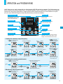
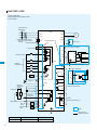
TERMINALS
Main Circuit Terminals
Terminal Description
Terminal Symbol
Terminal Name
R(L1), S(L2), T(L3)
Main power supply input terminals
U(T1), V(T2), W(T3)
Inverter output terminals
PD(+1), P(+)
DC reactor connection terminals
P(+), RB(RB)
External braking resistor connection terminals
P(+), N(-)
External braking unit connection terminals
(G)
Ground connection terminal
R0(R0), T0(T0)
Control power supply input terminals
Terminal Arrangement
110-150HFE2, 075-150HFU2/LFU2
015-055 LFU2, HFU2, HFE2
R
S
(L1) (L2)
R0 T0
(R 0) (T0)
PD
(+1)
T
U
P
N
RB
(-)
(+)
(RB)
185-370LFU2
185-750HFE2, HFU2
R
S
V
W
(G)
(G)
R
(L3) (T1) (T2) (T3)
PD
T PD P
N
U
T
U
V
W
(RB) (G)
(G)
(L3) (T1) (T2) (T3)
P
(+1)
N
RB
(-)
(+)
220, 300, 450, 550, 750LFU2
900-1320HFE2/HFU2
R0 T0
(R 0) (T0)
(G) (L1) (L2) (L3) (+1) (+)
S
(L1) (L2)
V W
R
(-) (T1) (T2) (T3) (G)
S
T PD P
(L1) (L2) (L3) (+1) (+)
R0 T0
(R 0) (T0)
R0 T0
(R 0) (T0)
N
U
V W
(-) (T1) (T2) (T3)
(G)
(G)
Screw Diameter and Terminal Width
R0,T0 Terminals
Main Circuit Terminals
Model
075LFU2
015-037 LFU2 055LFU2
110-150LFU2 185LFU2,185-370
220-370LFU2,
HFE2/HFU2 HFE2/HFU2 HFE2/HFU2 HFE2/HFU2
450-750HFE2/HFU2
HFE2/HFU2
450-550
LFU2
750LFU2,
1320HFE2/HFU2
900-1100
HFE2/HFU2
All models
Screw diameter
M4
M5
M5
M6
M6
M8
M10
M10
M10
M4
Terminal width (mm)
13
13
17.5
17.5
18
23
35
40
29
9
*For ground screw of 200, 300, 450, 550 LFU2, M6 is used. For 900-1320HFE/HFU2, M8 is used.
W
W:Terminal width
Control Circuit Terminals
Terminal Arrangement
H
L
O2
O
AM
OI
FM
AMI
TH
P24
FW
PLC
5
CM1
4
12C
3
12A
2
11C
1
11A
AL1
AL0
AL2
Screw diameter M3, Terminal width 6.4mm
17
Control Circuit Terminals
Terminal Description [ ]: Default setting (CE/UL)
Symbol
Name
L
Common Terminal for Analog
Power Source
Common terminal for H, O, O2, OI, AM, and AMI. Do not ground.
H
Power Source for Frequency
Setting
Power supply for frequency command input
O
Frequency Command Terminal
Maximum frequency is attained at DC 10V in DC 0-10V range. Set the
voltage at A014 to command maximum frequency below DC 10V.
Input impedance: 10kΩ, Allowable
input voltage range: DC -0.3-+12V
O2
Frequency Command Extra
Terminal
O2 signal is added to the frequency command of O or OI in DC
0-± 10V range. By changing configuration, frequency command
can be input also at O2 terminal.
Input impedance:10kΩ, Allowable
input voltage range: DC 0-± 12V
OI
Frequency Command Terminal
Maximum frequency is attained at DC 20mA in DC 4-20mA range.
When the intelligent terminal configured as AT is on, OI signal is enabled.
Input impedance: 100Ω, Allowable
input voltage range: DC 0-24mA
AM
Analog Output Monitor (Voltage)
DC 0-10V, 2mA max.
AMI
Analog Output Monitor (Current)
Selection of one function from:
Output frequency, output current, torque, output voltage, input
power, electronic thermal load ratio, and LAD frequency.
Power Supply
Analog
Frequency Setting
Monitor Output
Analog
Input
Sensor
TH
Thermistor Input Terminals
Relay
Output
Digital
The inverter trips when the external thermistor detects abnormal
temperature. Common terminal is CM1.
[Recommended thermistor characteristics]
Allowable rated power: 100mW or over. Impedance in the case of
abnormal temperature: 3k
Note: Thermal protection level can be set between 0 and 9999 .
FM
Digital Monitor (Voltage)
P24
Power Terminal for Interface
Internal power supply for input terminals. In the case of source
type logic, common terminal for contact input terminals.
CM1
Common Terminal for Interface
Common terminal for P24, TH, and FM. In the case of sink type logic, common terminal for contact input terminals. Do not ground.
Run
Command
FW
Forward Command Input
The motor runs forward when FW terminal is ON, and stops when
FW is OFF.
Functions
1
[RS/RS]
2
[AT/AT]
3
[CF2/USP]
4
[CF1/CF1]
5
[RV/RV]
Intelligent Input Terminals
Common
Terminal
PLC
Common Terminal for
Intelligent Input Terminals,
Common Terminal for
External Power Supply for
PLCs, etc.
State/
Alarm
12C
[RUN/RUN]
12A
[RUN/RUN]
11C
[FA1/FA1]
11A
[FA1/FA1]
AL0
[AL/AL]
AL1
[AL/AL]
AL2
[AL/AL]
Power Supply
Ratings
DC 10V, 20mA max.
[DC0-10V output (PWM output)] Selection of one function from:
Output frequency, output current, torque, output voltage, input
power, electronic thermal load ratio, and LAD frequency.
[Digital pulse output (Pulse voltage DC 0/10V)] Outputs the value
of output frequency as digital pulse (duty 50%)
Monitor Output
Contact
Input
Explanation of Terminals
DC 4-20mA, 250Ω max.
Allowable input voltage range
[Input Circuit ]
TH
Thermistor
CM1
DC0-5V
DC5V
10kΩ
1kΩ
Digital output frequency
range: 0-3.6kHz, 1.2mA max.
DC 24V, 100mA max.
[Input ON condition]
Voltage between each terminal
and PLC: DC 18V min.
Assign 5 functions to terminals.
(Refer to the standard specifications for the functions.)
[Input OFF condition]
Voltage between each terminal
and PLC: DC 3V max.
Input impedance between each
terminal and PLC: 4.7Ω
Select sink or source logic with the short-circuit bar on the control
terminals.
Sink logic: Short P24 to PLC / Source logic: Short CM1 to PLC.
When applying external power source, remove the short-circuit bar
and connect PLC terminal to the external device.
Assign 3 functions to two NO contacts
and one NO-NC contact.
(Refer to the standard specifications for the functions.)
Intelligent Output Terminals
Intelligent relay output terminals
12C
12A
11C
11A
NO contact X 2
AL0
AL1
AL2
NO-NC contact X 1
Allowable maximum voltage
between each terminal and
PLC: DC 27V
Maximum capacity of relays
11,12:
AC 250V, 5A(R load)/1A(I load)
DC 30V, 5A(R load)/1A(I load)
AL1-AL0:
AC 250V, 2A(R load)/0.2A(I load)
DC 30V, 8A(R load)/0.6A(I load)
AL2-AL0:
AC 250V, 1A(R load)/0.2A(I load)
DC 30V, 1A(R load)/0.2A(I load)
Minimum capacity of relays
11,12:
DC 1V, 1mA
AL1-AL0, AL2-AL0:
AC100V, 10mA DC5V, 100mA
18
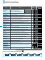
PROTECTIVE FUNCTIONS
Name
Over-current
protection
Display on digital
operator
Cause(s)
The inverter output was short-circuited, or the motor
shaft is locked or has a heavy load.
These conditions cause excessive current for the
inverter, so the inverter output is turned off.
While at constant speed
ERR1****
OC.Drive
During deceleration
OC.Drive
During acceleration
OC.Accel
Over.C
Others
Overload
protection(*1)
Braking resistor
overload protection
Over-voltage
protection
Display on remote
operator/copy unit
When a motor overload is detected by the electronic thermal function, the inverter
trips and turns off its output.
Over.L
When the regenerative braking resistor exceeds the usage time allowance or an over-voltage caused by the
stop of the BRD function is detected, the inverter trips and turns off its output.
OL.BRD
When the DC bus voltage exceeds a threshold, due to regenerative energy from
the motor, the inverter trips and turns off its output.
Over.V
When the built-in EEPROM memory has problems due to noise or excessive temperature, the inverter trips and turns off its output.
EEPROM
A decrease of internal DC bus voltage below a threshold results in a control circuit fault. This condition can
also generate excessive motor heat or cause low torque. The inverter trips and turns off its output.
Under.V
If a strong source of electrical interference is close to the inverter or abnormal operations occur in the builtin CT(Current transformer), the inverter trips and turns off its output.
CT
CPU error
When a malfunction in the built-in CPU has occurred, the inverter trips and turns off
its output.
CPU1
External trip
When a signal to an intelligent input terminal configured as EXT has occurred, the
inverter trips and turns off its output.
EXTERNAL
USP error
An error occurs when power is cycled while the inverter is in RUN mode if the Unattended Start Protection
(USP) is enabled. The inverter trips and does not go into RUN mode until the error is cleared.
USP
Ground fault
The inverter is protected by the detection of ground faults between the inverter output
and the motor during power-up tests. This feature protects the inverter only.
GND.Flt.
Input over-voltage
protection
Instantaneous
power failure
When the input voltage is higher than the specified value, it is detected 60 seconds
after power-up and the inverter trips and turns of its output.
OV.SRC
When power is cut for more than 15msec., the inverter trips and turns off its output. If power failure continues, the error will be cleared. The inverter restarts if it is in RUN mode when power is cycled.
Inst.P-F
Inverter thermal
trip
When the inverter internal temperature is higher than the specified value, the thermal sensor in the inverter
module detects the higher temperature of the power devices and trips, turning off the inverter output.
OH FIN
Gate array error
Communication error has occured between CPU and gate array.
Missing phase
One of three lines of 3-phase power supply is missing.
IGBT error
When instantaneous over-current has occurred, the inverter trips and turns off its
output to protect main circuit element.
IGBT
Thermistor error
When the thermistor inside the motor detects temperature higher than the specified
value, the inverter trips and turns off its output.
TH
EEPROM error(*2)
Under-voltage
error
CT(Current
transformer) error
Expansion card 1
connection error
GA
PH.Fail
Expansion card 2
connection error
Out of operation
due to under-voltage
–
OP1 0-9
–
OP2 0-9
An error has been detected in an expantion card or at its connecting terminals.
Due to insufficient voltage, the inverter has turned off its output and been trying to
restart. If it fails to restart, it goes into the under-voltage error.
UV.WAIT
(*1)You
(*2)If
can clear the error by pressing the Start / Reset key 10 seconds after the trip occurred.
an EEPROM error
occurs, be sure to confirm the parameter data values are still correct.
How to access the details about the present fault
Error code Status at trip point
19
Output frequency
at trip point
Motor current
at trip point
Voltage between
P(+) and N(–) at trip point
Cumulative inverter
operation (run) time
at trip point
Cumulative power-on
time at trip point
CONNECTING DIAGRAM
SOURCE TYPE LOGIC
In case of 400V class,
place a transformer for operating circuit
to receive 200V.
200V-240V±10%
50/60Hz±5%
R(L1)
L300P
(T1)U
S (L2)
(T2)V
T (L3)
R
(*2)Remove connection with J51
when RoTo power is supplied
externally
Control power source
(*2)
T(J51)
R0
T0
IM
(T3)W
(+1)PD
Removable terminals
DC link choke
P24
Dynamic braking unit (BRD)
Short-circuit bar
PLC
CM1
(+) P
AL1 AL2
FW
Forward command
RB
(-) N
P
RB
N
R1
5
R2
RB
P
AL1
AL2
RB
P
DC24V
4
Intelligent
input terminals
(5 terminals)
AL1
AL2
For 18.5kW(25HP) and over
3
AL0
+
FM Monitor output
(PWM)
AL2
11A
CM1
Thermistor
Frequency
setting device
500-2k
TH
11C
DC10V
H
12A
O
12C
P
P
RB
RB
N
Braking resistor (RB)
Intelligent output terminals
DC0-10V(12-bit)
Analog input
FM
(To operating circuit)
-
AL1
(Inverter)
For up to 15kW(20HP)
1
DC–10–+10V(12-bit)
O2
Current input
4-20mA(12-bit)
OI
10k
SP
10k
SN
100
L
RP
RS485
Serial communication port
Analog output
AM
DC0-10V
(8-bit)
DC4-20mA
(8-bit)
SN
AMI
(G)
Option
Customer wiring
(Outside the inverter)
Terminal Name
Common
FW, 1, 2, 3, 4, 5
P24
FM, TH
CM1
H, O, O2, OI, AM, AMI
L
20
SINK TYPE LOGIC
In case of 400V class,
place a transformer for operating circuit
to receive 200V.
200V-240V±10%
50/60Hz±5%
R(L1)
L300P
(T1)U
S (L2)
(T2)V
T (L3)
R
(*2)Remove connection with J51
when RoTo power is supplied
externally
Control power source
(*2)
T(J51)
R0
T0
IM
(T3)W
(+1)PD
Removable terminals
DC link choke
P24
Dynamic braking unit (BRD)
Short-circuit bar
PLC
(+) P
AL1 AL2
FW
RB
Forward command
(-) N
P
RB
N
R1
5
R2
4
For 18.5kW(25HP) and over
For up to 15kW(20HP)
1
AL2
FM
11A
Frequency
setting device
500-2k
11C
DC10V
H
12A
O
12C
P
P
RB
RB
N
Braking resistor (RB)
Intelligent output terminals
DC0-10V(12-bit)
Analog input
TH
(Inverter)
AL1
CM1
Thermistor
RB
P
AL0
2
+
AL1
AL2
DC24V
3
-
RB
P
(To operating circuit)
Intelligent
input terminals
AL1
AL2
DC–10–+10V(12-bit)
O2
Current input
4-20mA(12-bit)
OI
10k
SP
10k
SN
100
L
RP
RS485
Serial communication port
Analog output
DC0-10V
(8-bit)
AM
SN
AMI
DC4-20mA
(8-bit)
(G)
Option
Customer wiring
(Outside the inverter)
Terminal Name
Common
21
FW, 1, 2, 3, 4, 5, FM, TH
CM1
H, O, O2, OI, AM, AMI
L
CONNECTING TO PLC
1. USING INTERNAL POWER SUPPLY OF THE INVERTER
(1) Sink type logic
(2) Source type logic
S
P24
COM
P24
PLC
PLC
+
DC24V
FW
5
5
1
1
COM
CM1
Hitachi EH-150 series PLC
Output Module
EH-YT16
S
L300P
+
DC24V
FW
CM1
Hitachi EH-150 series PLC
Output Module
EH-YTP16
L300P
(Note:Place short-circuit bar between PLC and CM1 instead of P24 and PLC.)
2. USING EXTERNAL POWER SUPPLY
(1) Sink type logic
DC24V
+
-
S
(2) Source type logic
P24
COM
PLC
DC24V
+
DC24V
FW
COM
Hitachi EH-150 series PLC
Output Module
EH-YT16
P24
+
-
PLC
FW
5
5
1
1
S
CM1
L300P
(Note:Remove short-circuit bar between P24 and PLC.)
+
DC24V
Hitachi EH-150 series PLC
Output Module
EH-YTP16
CM1
L300P
(Note:Remove short-circuit bar between P24 and PLC.)
(Note:Be sure to turn on the inverter after turning on the PLC and its external power supply to prevent the parameters in the inverter from being modified.)
22
WIRING and ACCESSORIES
Power Supply
Fuse
200V
400V
R
(L1)
S
(L2)
T PD
(+1)
(L3)
Wiring
Motor
Output
(kW(HP))
Model
1.5(2)
2.2(3)
3.7(5)
5.5(8)
7.5(10)
11(15)
15(20)
18.5(25)
22(30)
30(40)
37(50)
45(60)
55(75)
75(100)
1.5(2)
2.2(3)
3.7(5)
5.5(8)
7.5(10)
11(15)
15(20)
18.5(25)
22(30)
30(40)
37(50)
45(60)
55(75)
75(100)
90(125)
110(150)
132(175)
L300P-015LFU2
L300P-022LFU2
L300P-037LFU2
L300P-055LFU2
L300P-075LFU2
L300P-110LFU2
L300P-150LFU2
L300P-185LFU2
L300P-220LFU2
L300P-300LFU2
L300P-370LFU2
L300P-450LFU2
L300P-550LFU2
L300P-750LFU2
L300P-015HFU2
L300P-022HFU2
L300P-040HFU2
L300P-055HFU2
L300P-075HFU2
L300P-110HFU2
L300P-150HFU2
L300P-185HFU2
L300P-220HFU2
L300P-300HFU2
L300P-370HFU2
L300P-450HFU2
L300P-550HFU2
L300P-750LFU2
L300P-900LFU2
L300P-1100LFU2
L300P-1320LFU2
Input
Voltage
Power Lines
2
AWG
mm
AWG 14
AWG 14
AWG 10
AWG 8
AWG 6
AWG 4
AWG 2
AWG 4 *2
AWG 1/0
AWG 2 *2
AWG 1 *2
AWG 1 *2(75°C)
AWG 2/0 *2
AWG 3/0 *2
AWG 18
AWG 16
AWG 14
AWG 12
AWG 10
AWG 8
AWG 6
AWG 6
AWG 4
AWG 3
AWG 4 *2
AWG 1
AWG 2 *2
AWG 1 *2
AWG 1 *2(75°C)
AWG 2/0 *2
AWG 2/0 *2
2.1
2.1
5.3
8.4
13.3
21.2
33.6
21.2 *2
53.5
33.8 *2
42.4 *2
42.4 *2
67.4 *2
85.0 *2
0.8
1.3
2.1
3.3
5.3
8.4
13.3
13.3
21.2
26.7
21.2 *2
42.4
33.8 *2
42.4 *2
42.4 *2
67.4 *2
67.4 *2
Signal
Lines
0.75mm2
shielded
wire
0.75mm2
shielded
wire
Fuse
(Class J)
10
15
20
30
40
60
70
90
100
150
175
200
250
300
10
10
15
15
20
30
35
50
50
70
80
100
125
150
200
225
300
Note 1: Field wiring connection must be made by a UL and c-UL listed closed-loop terminal connector sized for the
wire gauge involved. Connector must be fixed using the crimping tool specified by the connector manufacturer.
Note 2: Be sure to use bigger wires for power lines if the distance exceeds 20m(66ft).
P
(+)
Inverter
R0
T0
Name
RB
(-)N
(T1)
(T2)
(T3)
U
V
W
Input side AC reactor
EMI filter
Radio noise filter
Radio noise filter
(Capacitive filter)
DC link choke
Braking resistor
IM
Function
This is useful in suppressing harmonics induced on the power supply lines, or
when the main power voltage imbalance exceeds 3% (and power source capacity is more than 500kVA), or to smooth out line fluctuations. It also improves the
power factor.
This filter reduces the conducted noise in the power supply wiring between the inverter and the power distribution system. Connect it to the inverter primary (input side).
Electrical noise interference may occur on nearby equipment such as a radio
receiver. This magnetic choke filter helps reduce radiated noise (can also be
used on output).
This capacitive filter reduces radiated noise from the main power wires in the
inverter input side.
The choke suppresses harmonics generated by the inverter.
However, it will not protect the input diode bridge rectifier.
Braking unit
Braking components are useful for increasing the inverter's control torque for high
duty-cycle (on-off) applications, and improving the decelerating capability.
Output side noise filter
Reduces radiated noise from wiring in the inverter output side.
Radio noise filter
Electrical noise interference may occur on nearby equipment such as a radio
receiver. This magnetic choke filter helps reduce radiated noise (can also be
used on input).
AC reactor
This reactor reduces the vibration in the motor caused by the inverter's switching waveforms, by smoothing the waveforms to approximate commercial power quality. It is also useful when wiring from the inverter to
the motor is more than 10m in length, to reduce harmonics.
LCR filter
Sine wave shaping filter for the output side.
Motor
Note: An EMI filter is required for European EMC directive and C-Tick, but the others are not for this purpose.
23
ACCESSORIES
OPERATOR
Model
Potentiometer
Installation in L300P
Remote Control
Multilingual
Copy Function
OPE-S
(Standard for L300P)(OPE-SRE: Standard for L300P UL version)
OPE-SR/SRE
SRW-0EX
*OPE-SRE:
English overlay
REMOTE OPERATOR SRW-0EX(Optional)
CABLE FOR OPERATOR
Model
Cable Length
ICS-1
1m (3.3ft)
ICS-3
3m (9.8ft)
[Unit:mm (inch)]
Inches for reference only
DIMENSIONS
OPE-S(R)
SRW-0EX
80(3.15)
18(0 .71)
26.5(1.04)
POWER
ALARM
ALARM
Hz
V
A
PRG
POWER
RUN
PRG
kW
18(0.7 1)
%
( )
2
STR
Potentiometer is installed only in ORE-SR/SRE.
26.5(1.04)
18(0.71)
2(0.08)
READ
MON
0
FUN
REV RUN
2- 4(0.16)
L
STR
2
1
FWD RUN
COPY
3
2- 4( 0.16)
STOP/RESET
2-M3 depth5
(Reverse side)
59(2.32)
18(0 .71)
*
COPY
REMT
103(4.06)
1
103(4.06)
FUNC
6.5(0.26)
STOP/RESET
RUN
*
123(4.84)
79(3.11)
RUN
2(0 .08)
13(0.51) 8(0.31)
13(0.51) 8(0.31)
80(3.15)
ICS-1, 3
(Cables for OPE-S/SR/SRE
and SRW-0EX)
Mounting holes
Model Name
Cable Length
ICS-1
ICS-3
1m (3.3ft)
3m (9.8ft)
Mounting holes
24
EXPANSION CARD
Up to two expansion cards can be installed inside the L300P.
Digital Input Expansion Card
SJ-DG
Output frequency, acceleration time, deceleration time, and torque limit can be set by a digital output device
such as PLC, etc. (Binary or BCD)
Connecting Diagram
SJ-DG
Sequence error output terminal
Data Bit Configuration
Data input error
signal output
RY
SEQ
Item
D15
D14
D13
D12
D11
D10
D9
D8
D7
D6
D5
D4
D3
D2
D1
D0
Common terminal CMB
D15
D14
Data input terminal
D0
Strobe terminal STRB
Common terminal CM1
PLC, etc.
PLCB
P24B
Item
Output
Power supply
Mode 2
Data classification
code
Setting
data
Data can be
set by either
16-bit binary or
4-digit BCD.
Setting data
Data can be set by
either 16-bit binary
or 4-digit BCD.
Input data is divided
into upper 8-bit and
lower 8-bit.
*Data input mode is selected by the dip switch on the expansion card.
Standard Specifications
Input
Mode 1
Specification
Data setting signal
Strobe signal
Sequence error signal (Data input error signal)
Power supply for interface
D0,D1, … between D15 and PLCB
Between STRB and PLCB
Open collector output (sink/ source compatible)
DC+27V 50mA max., between SEQ and CMB
DC+24V 90mA max., between P24B and CM1
NO contact input (sink/ source compatible)
DeviceNet™ Expansion Card
SJ-DN
Specifications
General data
Physical
conformance data
Communication data
Applicable DeviceNet specification
Vendor name
Device profile name
Network consumption current
Connector type
Isolation of physical layer
Support LED
MAC ID setting
Default MAC ID
Transmission baud rate setting
Support transmission baud rate
Pre-defined master/slave connection set
UCMM Support
Support connection
Explicit message fragmentation
Dimensional drawings
Connector specifications
Manufacturer
Phoenix Contact
Volume 1-Relesse 2.0 Volume 2-Relesse 2.0
Hitachi, Ltd.
Vendor ID=74
Slave DC Drive
Profile No.=13
50mA
Open connector
Yes
Module status / network status
By digital operator
63
By digital operator
125k/250k/500k
Group 2 only server
None
Explicit message connection, Polled I/O connection
Yes
[Unit:mm]
Black
Model Code
MSTB 2.5/5-ST-5.08AU
Nameplate
Blue
White
Cable connection
No
1
2
3
4
5
Signal
VCAN_L
Drain
CAN_H
V+
Cable color
15
Black
Blue
–
White
Red
2.54
8.3
5.08
18.2
Note: Communication power supply (24VDC) is required in system configuration.
25
DeviceNet is a trademark of Open DeviceNet Vendor Association.
20.32
25.4
Red
PROFIBUS® Expansion Card
SJ-PBT
Specifications
Support profile
Transmission method
Connector type
Support file
ASIC chip
Maximum bus length
Maximum number of connectable nodes
Termination support
Support baud rate
Communication specification
Support LED
Connector specifications
Manufacturer
Phoenix Contact
Variable Speed Drive (Order no. 3.072)
RS-485
Open connector (6 poles)
GSD file
VPC3+ (Made by Profichip)
100m at 12Mbps, 1200m at 9.6kbps(No rooter used for both conditions)
126 (Rooter used), 32(No rooter used)
Yes (Bus topology termination enable)
9.6kbps to 12Mbps (Baud rate auto-detecting function equipped)
Master/slave
Fieldbus ON/Off-line
Fieldbus diagnosis
Communication Status
Dimensional drawings [Unit: mm]
Model Code
MC 1.5/6-ST-3.81
1
Cable connection
No
1
2
3
4
5
6
Signal name
NET-A
NET-B
Shield
NET-A
NET-B
Shield
Function
NET-A input connection
NET-B input connection
Cable shield connection
NET-A input connection
NET-B input connection
Cable shield connection
2
3
4
5
6
11.1
Note: PROFIBUS is a registered trademark of
Profibus Nutzer Organization.
2.3
3.81
6.6
19.05
23.65
15.5
LONWORKS® Expansion Card
SJ-LW
Specifications
Device Class
Transmission method
Connector type
LonMark Object Support
Support file
Neuron Chip
Max. bus length
Max. length between nodes
Max. nodes number
Termination support
Support transmission baudrate
Data type
Support LED
Dimensional drawings [Unit: mm]
Variable Speed Drive
FTT-10A (Free Topology Twisted Pair Transceiver)
Open connector
0000-Node Object
6010-Variable Speed Motor Drive
XIF
TMPN3120FE5M
2700m
500m
32,385
FT (Free topology termination enable)
NO (Termination disable)
BUS (Bus topology termination enable)
78kbps (Fixed)
Pier to Pier
Power /Inverter
LON diagnosis/ Service
Communication Status
11.1
2.3
7.62
15.5
Manufacturer
Phoenix Contact
Cable connection
1
Model Code
MC 1.5/3-ST-3.81
12.22
LONWORKS is a registered trademark of Echelon Corporation
No
Connector specifications
3.81
6.6
2
3
Signal name
Shield
Cable shield connection
NET-A
NET-A input connection
NET-B
NET-B input connection
Function
Note: Network function must be supported by the software of the inverter
used with SJ-DN, SJ-PBT, or SJ-LW.
For the detail, please contact Hitachi sales office.
26
FOR COMPACT PANEL
Heat accumulation in the panel can be reduced by arranging inverter heat sink outside.
L300P-015– 055LFU2,HFU2/E2
Panel
inside
L300P-075– 150LFU2, HFU2
-110– 150HFE2
Exhaust
Exhaust
Panel inside
L300P-370LFU2, HFU2/E2
L300P-185– 300LFU2, HFU2/E2
Exhaust
Exhaust
Panel inside
Panel inside
Air intake
Air
intake
d
Air
intake
d
Air intake
FP-2
(For the top
and the bottom
of the inverter)
d
FP-1
(For the top and the
bottom of the inverter)
L300P-450– 550LFU2
-450– 750HFU2/E2
L300P-750LFU2
FP-4
(For the sides
of the inverter)
L300P-900– 1100HFU2/E2
Panel
inside
Exhaust
Exhaust
d
FP-3
(For the top
and the bottom
of the inverter)
Panel
inside
FP-4
(For the top and the
bottom of the inverter)
L300P-1320HFU2/E2
Panel
inside
Exhaust
Exhaust
Panel inside
Air intake
d
d
d
d
FP-5
(For the sides
of the inverter)
FP-6
(For the sides
of the inverter)
FP-5
(For the top and
the bottom of
the inverter)
FP-6
(For the top and the
bottom of the inverter)
Panel cutout
4-Screw
H1
W1
W
27
Air
intake
Air
intake
Air
intake
H
Model
L300P-015–055LFU2, HFU2/E2
L300P-075–150LFU2, HFU2
-110 – 150HFE2
L300P-185-300LFU2, HFU2/E2
L300P-370LFU2, HFU2/E2
L300P-450 – 550LFU2, HFU2/E2
-450 – 750HFU2/E2
L300P-750LFU2
L300P-900 – 1100HFU2/E2
L300P-1320HFU2/E2
FP-7
(For the side
of the inverter)
FP-8
(For the side
of the inverter)
FP-7
(For the top
and the bottom
of the inverter)
FP-9
(For the top and
the bottom of
the inverter)
W
146
W1
130
H
280
H1
260
Screw
M6
d
62
206
189
285
265
M6
82
249
320
229
300
415
524
395
505
M6
M8
83
92
400
380
550
520
M10
102.7
490
400
490
510
420
510
710
710
750
670
690
710
M10
M10
M10
131
141
137
[Unit: mm]
TORQUE CHARACTERISTICS
Typical torque performance based on V/f pattern (top) is shown below.
150
Maximum torque
(for short time period,
maximum torque boosting)
130
125
Output torque (%)
V/f pattern
V
100(%)
(Continuous
operating torque)
100
95
90
80
75
(Base frequency 60Hz)
50
45
(Base frequency 50Hz)
25
1
1
–
–
50
60
100
120
(Hz)f
0
0 1 6 10
6
20
30
25
40
50
60
50
70
80
90
75
100
110
120
100
Frequency (Hz)
DERATING DATA
The L300P series can be used at ambient temperature of –10˚C to 50˚C.
However, when using at 40˚C or over, derating is required.
(1)Ambient temperature 40°C
(200V class)
015–150LFU2
450LFU2
185LFU2
370LFU2
220LFU2
90
80
550LFU2
300, 750LFU2
70
60
55
0.51
2
3
4
5
015–220HFU2/E2
100
Output current
(Ratio to the rating: %)
Output current
(Ratio to the rating: %)
100
900HFU2/E2
(400V class)
6 7 8 9 10 11 12
Carrier frequency (kHz)
450,550HFU2/E2
300HFU2/E2
90
370HFU2/E2
80
1100, 1320HFU2/E2
60
55
0.51
2
3
4
5
(200V class)
015-075LFU2
100
450LFU2
90
185LFU2
80
150LFU2
70
110LFU2
60
55
0.51
2
3
4
220LFU2
370LFU2
550LFU2
300LFU2
750LFU2
5
6
7 8 9 10 11 12
Carrier frequency (kHz)
1100, 1320HFU2/E2
6 7 8 9 10 11 12
Carrier frequency (kHz)
Output current
(Ratio to the rating: %)
Output current
(Ratio to the rating: %)
(2)Ambient temperature 50°C
100
750HFU2/E2
70
90
(400V class) 900HFU2/E2
185HFU2/E–220HFU2/E2
550HFU2/E
450HFU2/E2
80
150HFU2/E2
110HFU2/E2
70
60
55
015–075HFU2/E2
370HFU2/E2
300HFU2/E2
750HFU2/E2
0.51
2
3
4
5
6 7 8 9 10 11 12
Carrier frequency (kHz)
28
FOR CORRECT OPERATION
Application to Motors
[Application to general-purpose motors]
Operating frequency
The overspeed endurance of a general-purpose motor is 120% of the rated speed for 2 minutes (JIS C4,004). For operation
at higher than 60Hz, it is required to examine the allowable torque of the motor, useful life of bearings, noise, vibration, etc.
In this case, be sure to consult the motor manufacturer as the maximum allowable rpm differs depending on the motor
capacity, etc.
Torque characteristics
The torque characteristics of driving a general-purpose motor with an inverter differ from those of driving it using commercial power (starting torque decreases in particular). Carefully check the load torque characteristic of a connected machine
and the driving torque characteristic of the motor.
Motor loss and
temperature increase
An inverter-driven general-purpose motor heats up quickly at lower speeds. Consequently, the continuous torque level(output)
will decrease at lower motor speeds. Carefully check the torque characteristics vs speed range requirements.
Noise
When run by an inverter, a general-purpose motor generates noise slightly greater than with commercial power.
Vibration
When run by an inverter at variable speeds, the motor may generate vibration, especially because of (a) unbalance of the
rotor including a connected machine, or (b) resonance caused by the natural vibration frequency of a mechanical system.
Particularly, be careful of (b) when operating at variable speeds a machine previously fitted with a constant speed motor.
Vibration can be minimized by (1) avoiding resonance points using the frequency jump function of the inverter, (2) using a
tire-shaped coupling, or (3) placing a rubber shock absorber beneath the motor base.
Power transmission mechanism
Under continued, low-speed operation, oil lubrication can deteriorate in a power transmission mechanism with an oil-type
gear box (gear motor) or reducer. Check with the motor manufacturer for the permissible range of continuous speed. To
operate at more than 60 Hz, confirm the machine’s ability to withstand the centrifugal force generated.
[Application to special motors]
Gear motor
The allowable rotation range of continuous drive varies depending on the lubrication method or motor manufacturer. (Particularly in case of oil lubrication, pay attention to the low frequency range.)
Brake-equipped motor
For use of a brake-equipped motor, be sure to connect the braking power supply from the primary side of the inverter.
Pole-change motor
There are different kinds of pole-change motors (constant output characteristic type, constant torque characteristic type, etc.),
with different rated current values. In motor selection, check the maximum allowable current for each motor of a different
pole count. At the time of pole changing, be sure to stop the motor.
Submersible motor
The rated current of a submersible motor is significantly larger than that of the general-purpose motor. In inverter selection,
be sure to check the rated current of the motor. Also see: Application to the 400V-class motor.
Explosion-proof motor
Inverter drive is not suitable for a safety-enhanced explosion-proof type motor. The inverter should be used in combination
with a pressure-proof explosion-proof type motor.
*Explosion-proof verification is not available for L300P Series. For explosion-proof operation, use other series of motors.
Synchronous (MS) motor
High-speed (HFM) motor
In most cases, the synchronous (MS) motor and the high-speed (HFM) motor are designed and manufactured to meet the
specifications suitable for a connected machine. As to proper inverter selection, consult the manufacturer.
Single-phase motor
A single-phase motor is not suitable for variable-speed operation by an inverter drive. Therefore, use a three-phase motor.
[Application to the 400V-class motor]
A system applying a voltage-type PWM inverter with IGBT may have surge voltage at the motor terminals resulting from the cable constants including the
cable length and the cable laying method. Depending on the surge current magnification, the motor coil insulation may be degraded. In particular, when a
400V-class motor is used, a longer cable is used, and critical loss can occur, take the following countermeasures:
(1) install the LCR filter between the inverter and the motor,
(2) install the AC reactor between the inverter and the motor, or
(3) enhance the insulation of the motor coil.
Notes on Use
[Drive]
Run/Stop
Run or stop of the inverter must be done with the keys on the operator panel or through the control circuit terminals.
Do not operate by installing a electromagnetic contactor (Mg) in the main circuit.
Emergency motor stop
When the protective function is operating or the power supply stops, the motor enters the free run stop state. When an
emergency stop is required or when the motor should be kept stopped, use of a mechanical brake should be considered.
High-frequency operation
A max. 400Hz can be selected on the L300P Series. However, a two-pole motor can attain up to approx. 24,000 rpm, which
is extremely dangerous. Therefore, carefully make selection and settings by checking the mechanical strength of the motor
and connected machines. Consult the motor manufacturer when it is necessary to drive a standard (general-purpose)
motor above 60 Hz.
[Installation location and operating environment]
Avoid installation in areas of high temperature, excessive humidity, or where moisture can easily collect, as well as areas that are dusty, subject to corrosive
gasses, mist of liquid for grinding, or salt. Install the inverter away from direct sunlight in a well-ventilated room that is free of vibration. The inverter can be
operated in the ambient temperature range from –10 to 50°C. (Carrier frequency and output current must be reduced in the range of 40 to 50°C.)
29
[Main power supply]
Installation of an
AC reactor on the
input side
In the following examples involving a general-purpose inverter, a large peak current flows on the main power supply side,
and may destroy the converter module. Where such situations are foreseen or the connected equipment must be highly reliable, install an AC reactor between the power supply and the inverter. Also, where influence of indirect lightning strike is possible, install a lightning conductor.
(A) The unbalance factor of the power supply is 3% or higher. (Note)
(B) The power supply capacity is at least 10 times greater than the inverter capacity (the power supply capacity is 500
kVA or more).
(C) Abrupt power supply changes are expected.
Examples:
(1) Several inverters are interconnected with a short bus.
(2) A thyristor converter and an inverter are interconnected with a short bus.
(3) An installed phase advance capacitor opens and closes.
In cases (A), (B) and (C), it is recommended to install an AC reactor on the main power supply side.
Note: Example calculation with VRS = 205V, VST = 201V, VTR = 200V
VRS : R-S line voltage, VST : S-T line voltage, VTR : T-R line voltage
Max. line voltage (min.) – Mean line voltage
Unbalance factor of voltage = ——————————————————————— X 100
Mean line voltage
VRS – (VRS + VST + VTR )/3
205 – 202 X 100 = 1.5 (%)
= ————————————— X 100 = —————
202
(VRS + VST + VTR )/3
Using a private power
generator
An inverter run by a private power generator may overheat the generator or suffer from a deformed output voltage waveform
of the generator. Generally, the generator capacity should be five times that of the inverter (kVA) in a PWM control system,
or six times greater in a PAM control system.
Notes on Peripheral Equipment Selection
Wiring connections
Wiring
between
inverter and
motor
(1)Be sure to connect main power wires with R(L1), S(L2), and T(L3) (input) terminals and motor wires to U(T1), V(T2), and
W(T3) terminals (output). (Incorrect connection will cause an immediate failure.)
(2)Be sure to provide a grounding connection with the ground terminal ( ).
Electromagnetic contactor
When an electromagnetic contactor is installed between the inverter and the motor, do not perform on-off switching during
running operation.
Thermal relay
When used with standard applicable output motors (Hitachi standard three-phase squirrel-cage four-pole motors), the
L300P Series does not need a thermal relay for motor protection due to the internal electronic protective circuit. A thermal
relay, however, should be used:
during continuous running outside a range of 30 to 60 Hz.
for motors exceeding the range of electronic thermal adjustment (rated current).
when several motors are driven by the same inverter; install a thermal relay for each motor.
The RC value of the thermal relay should be more than 1.1 times the rated current of the motor. Where the wiring length is
10 m or more, the thermal relay tends to turn off readily. In this case, provide an AC reactor on the output side or use a
current sensor.
Installing a circuit breaker
Install a circuit breaker on the main power input side to protect inverter wiring and ensure personal safety. Choose an
inverter-compatible circuit breaker. The conventional type may malfunction due to harmonics from the inverter. For more
information, consult the circuit breaker manufacturer.
Wiring distance
The wiring distance between the inverter and the remote operator panel should be 20 meters or less. When this distance is
exceeded, use CVD-E (current-voltage converter) or RCD-E (remote control device). Shielded cable should be used on the
wiring. Beware of voltage drops on main circuit wires. (A large voltage drop reduces torque.)
Earth leakage relay
If the earth leakage relay (or earth leakage breaker) is used, it should have a sensitivity level of 15 mA or more (per inverter).
Phase advance capacitor
Do not use a capacitor for power factor improvement between the inverter and the motor because the high-frequency
components of the inverter output may overheat or damage the capacitor
High-frequency Noise and Leakage Current
(1) High-frequency components are included in the input/output of the inverter main circuit, and they may cause interference in a transmitter, radio, or sensor
if used near the inverter. The interference can be minimized by attaching noise filters (option) in the inverter circuitry.
(2) The switching action of an inverter causes an increase in leakage current. Be sure to ground the inverter and the motor.
Ambient temperature (°C)
Lifetime of Primary Parts
Because a smoothing capacitor deteriorates as it undergoes internal chemical reaction, it should normally be replaced
every five years. Be aware, however, that its life expectancy is considerably shorter when the inverter is subjected to
such adverse factors as high temperatures or heavy loads exceeding the rated current of the inverter.
The approximate lifetime of the capacitor is as shown in the figure at the right when it is used 12 hours daily (according to
the “Instructions for Periodic Inspection of General-Purpose Inverter” (JEMA)).
Also, such moving parts (cooling fan) should be replaced. Maintenance inspection and parts replacement must be
performed by only specified trained personnel.
50
40
30
2.5
5
10
Capacitor lifetime (years)
Precaution for Correct Usage
Before use, be sure to read through the Instruction Manual to insure proper use of the inverter.
Note that the inverter requires electrical wiring; a trained specialist should carry out the wiring.
The inverter in this catalog is designed for general industrial applications. For special applications in fields such as aircraft, outer space, nuclear
power, electrical power, transport vehicles, clinics, and underwater equipment, please consult with us in advance.
For application in a facility where human life is involved or serious losses may occur, make sure to provide safety devices to avoid a serious accident.
The inverter is intended for use with a three-phase AC motor. For use with a load other than this, please consult with us.
Information in this brochure is subject to change without notice.
30
Printed in Japan(H) SM-E232U 1006