1
Hitachi Gigabit Router
GR2000-B Series
Quick Start Guide
GR2K-GA-0008
Rev. 1.00
Hitachi Gigabit Router GR2000-B Series Quick Start Guide
Statement on EN55022 Compliance
WARNING: This is a Class A product. In a domestic environment this product may
cause radio interference in which case the user may be required to take adequate
measures.
Statement on Federal Communications Commission
(FCC) Compliance
This equipment has been tested and found to comply with the limits for a Class A
digital device, pursuant to Part 15 of the FCC Rules. These limits are designed to
provide reasonable protection against harmful interference when the equipment is
operated in a commercial environment. This equipment generates, uses, and can
radiate radio frequency energy and, if not installed and used in accordance with the
instruction manual, may cause harmful interference to radio communications.
Operation of this equipment in a residential area is likely to cause harmful
interference in which case the user will be required to correct the interference at his/
her own expense. The user is cautioned that changes or modifications not expressly
approved by the manufacturer could void the user’s authority to operate the
equipment.
Class A Emission Statement (Korea)
Trademarks
Ethernet is a product name of Xerox Corp., USA.
Ethernet is a trademark of Fuji Xerox Co., Ltd.
MS-DOS® is a registered trademark of Microsoft, Corp.
UNIX is a registered trademark, in the USA and other countries, licensed by X/Open Company Limited.
NetWare is a registered trademark of Novell, Inc., USA.
IPX is a registered trademark of Novell, Inc., USA.
HP OpenView is a trademark of Hewlett-Packard Company, USA.
Windows 95 is a trademark of Microsoft, Corp., USA.
Internet Explorer is a registered trademark of Microsoft, Corp., USA.
Netscape Navigator is a registered trademark of Netscape Communications Corporation.
All other brands and product names are trademarks of their respective holders.
Copyright 2002 Hitachi, Ltd. All Rights Reserved.
ii
GR2K-GA-0008
Rev. 1.00
Release 1.00 (August 2002)
This publication contains the most current information available to date. As new and
revised sections are received, new updates will be distributed.
Notice: No part of this publication may be reproduced or transmitted in any form or
by any means, electronic or mechanical, including photocopying and recording, or
stored in a database or retrieval system for any purpose without the expressed
written permission of Hitachi, Ltd.
Hitachi, Ltd. reserves the right to make changes to this document at any time
without notice, and assumes no responsibility for its use. All the features described
in this document may not be currently available.
Change Record
Revision
No.
Date
Description
Affected
Pages
1.00
August 2002
Initial Release
All
Preface
This manual presents simplified procedures for unpacking, setup and operating the
GR2000-B models. Before you begin to unpack and use the GR2000-B, read the
“Safety” pages at the beginning of this manual, which gives you directions necessary
to handle the GR2000 safely.
Information contained in this manual is subject to change without prior notice.
GR2K-GA-0008
Rev. 1.00
iii
Hitachi Gigabit Router GR2000-B Series Quick Start Guide
Abbreviations
AAL
ATM Adaptation Layer
ABR
Available Bit Rate
AFI
Authority and Format Indicator
AIS
Alarm Indication Signal
ANSI
American National Standards Institute
ARP
Address Resolution Protocol
AS
Autonomous System
ATM
Asynchronous Transfer Mode
BECN
Backward Explicit Congestion Notification
BGP
Border Gateway Protocol
BGP4
Border Gateway Protocol 4
BGP4+
Multiprotocol Extensions for Border Gateway Protocol - version
4
BOD
Bandwidth On Demand
BPDU
Bridge Protocol Data Unit
CATV
Cable Television
CBR
Constant Bit Rate
CIDR
Classless Inter-Domain Routing
CIR
Committed Information Rate
CLLM
Consolidated Link Layer Management
CLNP
Connectionless Network Protocol
CLP
Cell Loss Priority
CRC
Cyclic Redundancy Check
CR-LDP
iv
Constraint-Based Label Distribution Protocol
CSMA/CD
Carrier Sense Multiple Access with Collision Detection
DA
Destination Address
DCC
Data Country Code
DCE
Data Circuit terminating Equipment
DDP
Datagram Delivery Protocol
DHCP
Dynamic Host Configuration Protocol
DLCI
Data Link Connection Identifier
DSAP
Destination Service Access Point
DSCP
Differentiate Services Code Point
DSP
Domain Specific Part
GR2K-GA-0008
Rev. 1.00
GR2K-GA-0008
Rev. 1.00
DSU
Digital Service Unit
DTE
Data Terminal Equipment
DVMRP
Distance Vector Multicast Routing Protocol
ELAN
Emulated LAN
ERP
Echo Response
ERQ
Echo Request
ES
End System
FCS
Frame Check Sequence
FDB
Filtering Data Base
FDDI
Fiber Distributed Data Interface
FEC
Forwarding Equivalence Class
FERF
Far End Receive Failure
GFR
Guaranteed Frame Rate
HDLC
High-level Data Link Control
HNA
Hitachi Network Architecture
ICMP
Internet Control Message Protocol
ICMPv5
Internet Control message protocol version6
IEEE
Institute of Electrical and Electronics Engineers, Inc.
IETF
the Internet Engineering Task Force
IDI
Initial Domain Identifier
IGMP
Internet Groupe Management Protocol
ILMI
Interim Local Management Interface
IP
Internet Protocol
IPv4
Internet protocolversion 4
IPv6
Internet Protocol version 6
IPv6cp
Ipv6 Control Protocol
IPX
Internetwork Packet Exchange
ISO
International Organization for Standardization
ISP
Internet Service Provider
ITU-T
International Telecommunication Union - Telecommunication,
Standardization Sector
JDI
Japanese Domain Identifier
LAN
Local Area Network
LAPB
Link Access Procedure Balanced Mode
LCP
Link Control Protocol
LDP
Label Distribution Protocol
v
Hitachi Gigabit Router GR2000-B Series Quick Start Guide
vi
LEC
LAN Emulation Client
LES
LAN Emulation Server
LIS
Logical IP Subnetwork
LLB
Local Loop Back
LLC
Logical Link Control
LQM
Link Quality Monitoring
LQR
Link Quality Report
LSP
Label Switched Path
LSR
Label Switched Router
MAC
Media Access Control
MC
Memory Card
MD5
Message Digest 5
MIB
Management Information Base
MMF
Multi Mode Fiber
MPLS
Multi-Protocol Label Switching
MRU
Maximum Receive Unit
NSAP
Network Service Access Point
MTU
Maximum Transfer Unit
NBP
Name Binding Protocol
NCP
Network Control Protocol
NDP
Neighber Discovery Protocol
NET
Network Entity Title
NetBIOS
Network Basic Input/Output System
NIF
Network Interface board
NRZ
Non-Return-to-Zero
NSAP
Network Service Access Point
OC-3c
Optical Carrier level 3 concatenation
OC-12c
Optical Carrier level 12 concatenation
OAM
Operation Administration and Management
OSI
Open Systems Interconnection
OSPF
Open Shortest Path First
OUI
Organizationally Unique Identifier
PC
Personal Computer
PDB
Permanent Data Base
PHY
PHYsical layer protocol
PID
Protocol IDentifier
GR2K-GA-0008
Rev. 1.00
PIM
Protocol Independent Multicast
PIM-DM
Protocol Independent Multicast -Dense Mode
PIM-SM
Protocol Independent Multicast -Sparse Mode
PLD
Programmable Logic Design
POS
PPP over SONET/SDH
PPP
Point-to-Point Protocol
PPS
Packet Per Second
PVC
Permanent Virtual Channel (Connection)/Permanent Virtual
Circuit
QoS
Quality of Service
RA
Router Advertisment
RFC
Request For Comments
RIP
Routing Information Protocol
RIPng
Routing Information Protocol Next Generation
RLB
Remote Loop Back
RM
Routing Manager
RPF
Reverse Path Forwarding
RP
Routing Processor
RSVP
GR2K-GA-0008
Rev. 1.00
Resource Reservation Protocol
SA
Source Address
SAP
Service Access Point
SD
Start Delimiter
SDH
Synchronous Digital Hierarchy
SDLC
Service Advertising Protocol
SD-I
Super Digital I interface
SFD
Start Frame Delimiter
SMF
Single Mode Fiber
SNA
Systems Networking Architecture
SNAP
Sub-Network Access Protocol
SNMP
Simple Network Management Protocol
SONET
Synchronous Optical Network
SPT
Spanning Tree
SPX
Sequenced Packet Exchange
SSAP
Source Service Access Point
SSP
Switch to Switch Protocol
SVC
Switched Virtual Channel (Connection)
vii
Hitachi Gigabit Router GR2000-B Series Quick Start Guide
SW
Switch
TA
Terminal Adapter
TCC
Transmission Control Character
TCP/IP
Transmission Control Protocol/Internet Protocol
TOS
Type Of Service
TTC
Telecommunication Technology Committee
TTL
Time To Live
UBR
Unspecified Bit Rate
UDP
User Datagram Protocol
UNI
User Network Interface
VBR
Variable Bit Rate
VC
Virtual Channel/Virtual Call
VCI
Virtual Channel Identifier
VP
Virtual Path
VPI
Virtual Path Identifier
WAN
Wide Area Network
WS
Work Station
WWW
World-Wide Web
xDSL
viii
x Digital Subscriber Line
GR2K-GA-0008
Rev. 1.00
Safety Guide
This document provides safety-related notices for use of the GR2000 Gigabit Router.
Read the following Safety Guidelines carefully before using the product and follow
them to take full advantage of the GR2000’s features.
General Safety Guidelines
Perform all operations in accordance with the instructions and procedures as
described in the product manuals.
Be alert and use common sense. The hazard warnings cannot cover every
possible situation. Do not perform any operations not described in the
documentation. In the event of a problem, turn off the power, unplug the power
cable, and contact a qualified service technician.
Follow all precautionary and hazard messages on the GR2000 and in the
documentation. Failure to do so may result in bodily injury, damage to the
device, or an interruption in service.
The hazard warnings on the machine or in the manual have the following
headings and symbols, CAUTION or WARNING. Hazard warnings on the device
and in the manuals are provided to prevent or reduce risk of death, personal
injury, or product damage. Understand and follow these hazard warnings:
!
Caution: This is a caution notice. Follow the instructions in this notice to avoid
damage to the equipment or a disruption in service.
DANGER: This is a warning notice. Follow the instructions in this notice to avoid
the possibility of bodily injury occurring.
The following sections have specific instructions regarding warnings and cautions.
GR2K-GA-0008
Rev. 1.00
ix
Hitachi Gigabit Router GR2000-B Series Quick Start Guide
Specific Warning Instructions
DANGER: Failure to follow the instructions in this section could cause bodily
injury or death to the user.
x
Do not operate the device if you suspect damage or failure.
Do not use the device if there is smoke or an unusual smell coming from the
system. If either occurs, immediately turn power off and unplug the power cable
from the outlet. Contact a qualified service technician.
In the case of the GR2000-20H, GR2000-10H, or GR2000-6H with DC power
supplies installed, turn off the circuit breaker on the power facility supply side.
If the device is installed in a rack, unplug the device power cable from the rack
outlet. If the component with the problem cannot be identified, remove all power
cables from the rack outlet. Contact a qualified service technician.
In the case of redundant power supplies, make sure that ALL switches and
circuit breakers are turned off.
If the device is dropped and any part is broken, turn the power switch off, unplug
the power cable from the outlet, and contact service. Continued use may cause
fire or electric shock.
Do not use any unspecified power source or power voltage. Observe all terminal
ratings and markings on the product.
To prevent electric shock, use only grounded power outlets when using AC
power. Do not overload power outlets. In the case of DC power or the
GR2000-20H, use a ground wire to prevent electric shock.
Do not use adapters to connect multiple power cables to the same outlet. Use
standard safety procedures with the power cable.
Use only the power cable supplied with the device. Use of other cables may cause
fire or electric shock. Keep the power cable away from extreme heat.
Similarly, do not use the provided power cable for products other than the
GR2000, since this could cause a fire or electrical shock hazard.
Do not operate the device in wet or damp conditions
If liquid is spilled on the device, turn power off and unplug the power cable from
the outlet. Discontinue use to avoid the risk of fire or electric shock.
Place device on a stable, level surface. Do not place or stack objects on top of the
device.
If a foreign object falls into the device, turn power off and unplug the power cable
from the outlet. Do not attempt to remove the object while the power is on.
Do not remove the device’s cover while the device is in operation.
Touching internal parts may cause electric shock. Contact a qualified service
technician for any internal inspection, adjustment or repair. Do not modify the
device. Doing so may cause fire or electric shock.
Do not insert any foreign objects into the device or the ventilation slots. Doing so
may cause fire or electric shock.
Do not insert hands or any other object into a fan.
Do not allow unauthorized users of the device to pull out boards or power
supplies at any time.
Do not set the GR2000 in a dusty or humid location. Doing so may cause fire or
electric shock.
GR2K-GA-0008
Rev. 1.00
This router contains a lithium battery for the real-time clock. Mishandling this
battery may cause heat build-up, damage, or in an extreme case, explosion or
fire.
Do not remove the battery from the device, disassemble it, or expose it to
temperatures of over 100°C (212°F)
Do not throw or immerse lithium batteries into water.
Dispose of exhausted batteries as required by local regulations.
Remove dust on and around the device regularly. Dust buildup can cause fire or
electrical shock, and can result in failure of the device.
The power supply of the GR2000-6H weighs 8 kg. Handle with care, since it could
cause injury if it is dropped.
Specific Caution Instructions
!
Caution: This is a caution notice. Follow the instructions in this notice
to avoid damage to the equipment or a disruption in service.
Condensation may form on the surface and inside the device if it is moved from a
cold to a warm location. Using the device in this condition may cause fire or
electric shock. After moving the device between two locations with a large
temperature variation, let the device stand for a few hours before using.
Do not block the device’s ventilation.
Move the device carefully. Before moving the device, unplug the power cable,
disconnect all exterior devices, and remove the stabilization clamps. Failure to
follow this warning may damage the device or power cable, causing fire or electric
shock.
Do not hold the device by the front and back when moving; the cover may come
off, causing the device to fall.
Do not subject the device to extreme temperatures.
Do not place the device in direct sunlight or near heat sources that may cause
damage.
A yellow label designates that a Class 1 laser is being used. Light emission is
minimal and not hazardous, but avoid looking directly into the laser beam.
Approximate weights of the GR2000 models are as follows:
GR2K-GA-0008
Rev. 1.00
GR2000-1B: Approx. 6 kg. (13.2 lbs.)
GR2000-2B: Approx. 7 kg. (15.4 lbs.)
GR2000-2S: Approx. 15 kg. (33 lbs.)
GR2000-4S: Approx. 21 kg. (46 lbs.)
GR2000-6H: Approx. 55 kg. (121 lbs.)
GR2000-10H: Approx. 120 kg. (264 lbs.)
GR2000-20H: Approx. 160 kg. (352 lbs.)
xi
Hitachi Gigabit Router GR2000-B Series Quick Start Guide
Other Instructions
Cleaning
Clean the device only with a clean, dry cloth or use a cloth that has been
dampened with water or another pH-neutral liquid and thoroughly wrung out.
Do not use volatile organic solutions such as benzene or paint thinner,
chemicals, chemically treated cloths or pesticides, which may deform, discolor or
damage the device.
Storage
Unplug the power cable from the outlet when the device is not used for long periods.
xii
GR2K-GA-0008
Rev. 1.00
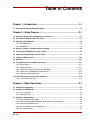
Table of Contents
Chapter 1 - Introduction..........................................................................1-1
1.1 Documents about the GR2000-B models....................................................................................... 1-1
Chapter 2 - Setup Process......................................................................2-1
2.1 Check that All Necessary Components are Present..................................................................... 2-1
2.2 Assemble the Required Tools for Setup........................................................................................ 2-1
2.3 Setting Up the GR2000-B................................................................................................................. 2-2
2.3.1 The GR2000-1B ....................................................................................................................... 2-2
2.3.2 GR2000-2B............................................................................................................................... 2-3
2.4 Dangers, Cautions, and Notes Regarding Setup .......................................................................... 2-5
2.5 Installing the GR2000-B on a Table or Desk.................................................................................. 2-6
2.6 Attaching and Detaching the Power Cable.................................................................................... 2-7
2.7 Installing a Memory Card ................................................................................................................ 2-8
2.8 Software .......................................................................................................................................... 2-10
2.9 The Setup Terminal and Cable Connections............................................................................... 2-11
2.9.1 Setup Terminal ....................................................................................................................... 2-11
2.9.2 Connecting Cable ................................................................................................................... 2-11
2.9.3 Connecting a Setup Terminal to the GR2000-B ..................................................................... 2-12
2.9.4 Connecting the GR2000-B to Other Devices.......................................................................... 2-12
2.9.5 Turning the Power Switch ON ................................................................................................ 2-13
2.10 Normal Start-Up Process for the GR2000-B .............................................................................. 2-13
2.10.1 Turning the Power OFF ........................................................................................................ 2-13
Chapter 3 - Basic Operations .................................................................3-1
3.1 Configuration Examples.................................................................................................................. 3-1
3.2 Startup of the GR2000-B.................................................................................................................. 3-2
3.2.1 First-Time Login........................................................................................................................ 3-2
3.2.2 Setting the Time ....................................................................................................................... 3-2
3.3 Setting the Configuration ................................................................................................................ 3-3
3.3.1 Enter the Administrator Mode ................................................................................................... 3-3
3.3.2 Enter the Configuration Edit Mode (Begin Editing the Configuration) ...................................... 3-3
3.3.3 Open the Configuration File...................................................................................................... 3-4
3.3.4 Set an IP Address for the Ethernet Port ................................................................................... 3-4
3.3.5 Set a Default Route .................................................................................................................. 3-4
GR2K-GA-0008
Rev. 1.00
xiii
Hitachi Gigabit Router GR2000-B Series Quick Start Guide
3.3.6 Check the Configuration You Set by Displaying its Information ............................................... 3-5
3.3.7 Save the Configuration Information Into the Configuration File................................................ 3-5
3.3.8 Close the Configuration File ..................................................................................................... 3-5
3.3.9 Return to the Administrator Mode............................................................................................. 3-5
3.3.10 Exit the Configuration Edit Mode (Finish Editing the Configuration)....................................... 3-6
3.4 Display of Operation Status ............................................................................................................ 3-7
3.4.1 Display of the Operation Status Covering the Entire Router .................................................... 3-7
3.4.2 Display of the Operation Status of the Built-In Ethernet ........................................................... 3-8
3.4.3 Display of the Operation Status of the Interface Configured .................................................... 3-8
3.4.4 Display of the Routing Table .................................................................................................... 3-8
3.5 More Details About Operation ........................................................................................................ 3-9
Chapter 4 - Troubleshooting ................................................................. 4-1
4.1 Troubleshooting for Operations Introduced in this Guide........................................................... 4-1
4.2 More Details About Troubleshooting ............................................................................................. 4-2
xiv
GR2K-GA-0008
Rev. 1.00
List of Figures
Chapter 1 - Introduction..........................................................................1-1
Figure 1-1. Documentation for the GR2000-B Series......................................................................... 1-2
Chapter 2 - Setup Process......................................................................2-1
Figure 2-1. GR2000-1B Front View ...................................................................................................... 2-2
Figure 2-2. GR2000-1B Rear View........................................................................................................ 2-3
Figure 2-3. GR2000-2B Front View ...................................................................................................... 2-3
Figure 2-4. GR2000-2B Rear View........................................................................................................ 2-4
Figure 2-5. Attaching the Rubber Feet ................................................................................................ 2-6
Figure 2-6. Connecting a Power Cable to the GR2000-B................................................................... 2-7
Figure 2-7. Locking the Power Cable into Place ................................................................................ 2-7
Figure 2-8. Location of Power Switch ................................................................................................. 2-8
Figure 2-9. Installation of a Memory Card........................................................................................... 2-8
Figure 2-10. After Installation of a Memory Card ............................................................................... 2-9
Figure 2-11. Locking a Memory Card .................................................................................................. 2-9
Figure 2-12. Unlocking a Memory Card............................................................................................... 2-9
Figure 2-13. Removing a Memory Card............................................................................................. 2-10
Figure 2-14. Memory Card Removed................................................................................................. 2-10
Figure 2-15. Connecting a Setup Terminal to the GR2000-B .......................................................... 2-12
Figure 2-16. Switching Power ON and OFF ...................................................................................... 2-13
Chapter 3 - Basic Operations .................................................................3-1
Figure 3-1. Example of a GR2000-B Connecting to Other Devices .................................................. 3-1
Chapter 4 - Troubleshooting ..................................................................4-1
GR2K-GA-0008
Rev. 1.00
xv
Hitachi Gigabit Router GR2000-B Series Quick Start Guide
This page left intentionally blank
xvi
GR2K-GA-0008
Rev. 1.00
List of Tables
Chapter 1 - Introduction..........................................................................1-1
Chapter 2 - Setup Process......................................................................2-1
Table 2-1. Specifications Required for Setup Terminals................................................................. 2-11
Table 2-2. Pinout for RS-232C Cable ................................................................................................. 2-11
Chapter 3 - Basic Operations .................................................................3-1
Table 3-1. Details About Other Settings.............................................................................................. 3-9
Chapter 4 - Troubleshooting ..................................................................4-1
Table 4-1. Types of Trouble and Corrective Action ........................................................................... 4-1
Table 4-2. Troubleshooting and Reference manuals......................................................................... 4-2
GR2K-GA-0008
Rev. 1.00
xvii
Hitachi Gigabit Router GR2000-B Series Quick Start Guide
This page left intentionally blank
xviii
GR2K-GA-0008
Rev. 1.00
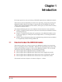
Chapter 1
Introduction
We deeply appreciate your purchasing a HITACHI Gigabit Router GR2000-B models.
This manual presents simplified procedures for unpacking, setup and operating the
GR2000-B models. Before you begin to unpack and use the GR2000-B, read the
“Safety” pages at the beginning of this manual, which gives you directions necessary
to handle the GR2000 safely.
The chapters following this one cover subjects of most interest to new customers:
1.1
Chapter 2 explains briefly about the process of unpacking the GR2000-B models
and setting them up.
Chapter 3, explains briefly about the operations of the GR2000-B models, such
as those for logging in, setting the time/configurations, or excuting operational
commands.
Chapter 4 gives information about the troubleshooting communication problems
or an apparently malfunctioning GR2000-B.
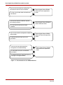
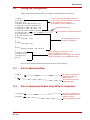
Documents about the GR2000-B models
This manual guides you on how to operate the GR2000-B models from unpacking
them to inputting the basic commands. Mind that the information given here is the
minimum knowledge necessary to start up the GR2000-B models. For the detailed
information about the GR2000-B, see the following manuals:
Hitachi Gigabit Router GR2000-B Series Installation Guide
Hitachi Gigabit Router GR2000 Series Enhanced Version Applications Guide
Hitachi Gigabit Router GR2000 Series Enhanced Version Configuration Guide
Hitachi Gigabit Router GR2000 Series Enhanced Version Operations Guide
The manuals and their subjects are shown in Figure 1-1 below.
GR2K-GA-0008
Rev. 1.00
1-1
Hitachi Gigabit Router GR2000-B Series Quick Start Guide
If you want to know about the configuration
and functional overview of the hardware …
or if you want to know about the functions of
the software …
If you want to know the conditions required
for installing hardware...
Hitachi Gigabit Router GR2000
Enhanced Version Applications
Guide
Hitachi Gigabit Router GR2000-B
Series Installation Guide
or if you want to know how to handle
hardware...
If you want to know the configuration method
and examples...
Hitachi Gigabit Router GR2000
Enhanced Version Configuration
Guide
or detailed command input syntax and
parameters …
If you want to know about operations
management and troubleshooting …
or command input syntax and detailed
parameters
Hitachi Gigabit Router GR2000
Enhanced Version Operations
Guide
or detailed information about operation log
messages and supported MIBs
Figure 1-1 Documentation for the GR2000-B Series
1-2
GR2K-GA-0008
Rev. 1.00
Chapter 2
Setup Process
This chapter explains briefly about the whole process from unpacking a product
package to powering up the GR2000-B.
2.1
2.1, “Check that All Necessary Components are Present,” on page 2-1
2.2, “Assemble the Required Tools for Setup.,” on page 2-1
2.3, “Setting Up the GR2000-B,” on page 2-2
2.4, “Dangers, Cautions, and Notes Regarding Setup,” on page 2-5
2.5, “Installing the GR2000-B on a Table or Desk,” on page 2-6
2.6, “Attaching and Detaching the Power Cable,” on page 2-7
2.7, “Installing a Memory Card,” on page 2-8
2.8, “Software,” on page 2-10
2.9, “The Setup Terminal and Cable Connections,” on page 2-11
2.10, “Normal Start-Up Process for the GR2000-B,” on page 2-13
Check that All Necessary Components are Present
Before you unpack the GR2000-B, find the packing list and check the contents of the
box against the list. Make sure that all components are present before you begin the
setup process.
2.2
Assemble the Required Tools for Setup.
Make sure you have the following tools before you begin setup. The only tools
required to install and set up a GR2000-B router are:
A #2 Phillips screwdriver for attaching the GR2000-B to a rack
A medium-sized flat-blade screwdriver for attaching cables.
GR2K-GA-0008
Rev. 1.00
2-1
Hitachi Gigabit Router GR2000-B Series Quick Start Guide
2.3
Setting Up the GR2000-B
2.3.1
The GR2000-1B
The GR2000-1B has the following hardware features:
Two built-in Ethernet ports 10BASE-T/100BASE-TX,
One slot for a network interface board, and
Two MC (memory card) slots.
Figures 2-1 and 2-2 show the front and rear views of the GR2000-1B, respectively.
Network Interface
Slot 0
(NIF 0)
Memory Cards
Slot 1
(MEM CARD 1)
Slot 0
(MEM CARD 0)
RS-232C
Connector
(CONSOLE)
Built-In Ethernet
10BASE-T/100BASETX
1 (LINE 1)
0 (LINE 0)
Figure 2-1 GR2000-1B Front View
*
2-2
Note: For the details about connectors, indicators, and switches, see the GR2000-B
Installation Guide.
GR2K-GA-0008
Rev. 1.00
Setup Process
Power Plug with
Locking Bail
Power Switch
Figure 2-2 GR2000-1B Rear View
2.3.2
GR2000-2B
The GR2000-2B has the following hardware features.
Four built-in Ethernet ports 10BASE-T/100BASE-TX,
Two slot for network interface boards, and
Two MC (Memory Card) slots.
Figure 2-3 shows the front view of the GR2000-2B with both option slots filled.
Figure 2-4 show the rear view of the GR2000-2B.
Network Interface Slots
1 (NIF 1)
0 (NIF 0)
Memory Cards
Slot 1
(MEM CARD 1)
Slot 0
(MEM CARD 0)
RS-232C
Connector
(CONSOLE)
Built-In Ethernet
10BASE-T/100BASETX
3 (LINE 3)
2 (LINE 2)
1 (LINE 1)
0 (LINE 0)
Figure 2-3 GR2000-2B Front View
GR2K-GA-0008
Rev. 1.00
2-3
Hitachi Gigabit Router GR2000-B Series Quick Start Guide
*
Note: For the details about connectors, indicators, and switches, see the GR2000-B
Installation Guide.
Power Plug with
Locking Bail
Power Switch
Figure 2-4 GR2000-2B Rear View
2-4
GR2K-GA-0008
Rev. 1.00
Setup Process
2.4
Dangers, Cautions, and Notes Regarding Setup
Below are collected some important messages regarding installation of the GR2000-B
router.
!
DANGER:
Do not put the router on an unstable or uneven surface. Instead, always
place the router on a stable, flat surface to prevent it from falling and
causing a physical damage to equpment or those near the unit.
DANGER:
When installing the router on a desk, lay it down horizontally. If you stand it
vertically or lean it against a wall, it can easily fall down and cause a damage
to yourself and the router.
Caution:
Do not block the ventilation slots on the sides of the router. If you block the
ventilation slots, the inside of the router will overheat up and malfunction or
even cause a fire. Secure a space of 70mm from around the ventilation slots.
Do not put objects weighing more than 5 kg (11 lbs.) on the router.
Otherwise, you can damage the router, or cause it to fall.
!
*
GR2K-GA-0008
Rev. 1.00
Caution:
When working around the router, wear a wrist strap to prevent static
electricity discharge. Without a wrist strap, the GR2000-B might be damaged
due to static electricity.
Note: Place the GR2000-B in a position where you can easily check the condition of the
front panel indicators.
- Protect cables by running them through a duct or by using a braid. Especially
for optical fiber cables, a cord bend radius of at least 100 mm in length and 50 mm
in breadth and a metal braid are necessary to protect them.
- For optical fiber cables, leave a 3 m length of cable for maintenance. Wind the
rest of the cable and store it near the GR2000-B. If an optical fiber cable and other
types of interface cables coexist, do not stress the optical fiber cable, since it can
break.
2-5
Hitachi Gigabit Router GR2000-B Series Quick Start Guide
2.5
Installing the GR2000-B on a Table or Desk
You can install the GR2000-B on a stable and flat table or desk. Install the router
according to the following procedures. If you want to install a GR2000-B in a rack,
see the GR2000-B Installation Guide.
*
Note: Do not attach the rubber stoppers to the router when installing it into a rack.
1. Place the router upside down on a flat, clean surface.
2. As shown in Figure 2-5, attach the rubber feet to the 1.5 mm holes (4 holes in
all).
Attach Rubber Feet
to 1.5 mm holes (4)
Figure 2-5 Attaching the Rubber Feet
3. Turn over the router and install it on a desk.
2-6
GR2K-GA-0008
Rev. 1.00
Setup Process
2.6
Attaching and Detaching the Power Cable
DANGER:
To prevent the possibility of electric shock, use only grounded power
outlets.
1. As shown in Figure 2-6, attach the power cable to the connector at the back of
the GR2000-B.
Metal bail to lock
power cable in
place
AC Connector
Power cable
Figure 2-6 Connecting a Power Cable to the GR2000-B
2. As shown in Figure 2-7, lock the power cable connector into place on the
GR2000-B chassis.
Push down the locking metal
bail toward the direction
indicated by the arrow in the
figure below.
Figure 2-7 Locking the Power Cable into Place
*
GR2K-GA-0008
Rev. 1.00
Note: When pulling a cable out of the connector, follow the procedures above in
reverse order.
2-7
Hitachi Gigabit Router GR2000-B Series Quick Start Guide
1. As shown in Figure 2-7, make sure that the power switch is depressed in the OFF
(0) position and plug the other end of the cable into the AC outlet you plan to use.
ON
OFF
Power Switch
Figure 2-8 Location of Power Switch
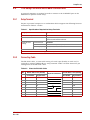
2.7
Installing a Memory Card
This procedure shows the process for installing and removing a memory card from
memory card slot 0. The operations for the memory card slot 1 are same as those for
the memory card slot 0.
(1) Installing a Memory Card
1. Insert a memory card in the position shown in Figure 2-9 and Figure 2-10 below.
When successfully inserted the lever next to the slot will be pushed forward.
Memory Card
(Part number
should be face up)
Memory Card
Slot
Figure 2-9 Installation of a Memory Card
*
2-8
Note: When inserting a memory card, the surface labeled with the part number
“HN-F9531-MC64X (BMC64)” should be face up.
GR2K-GA-0008
Rev. 1.00
Setup Process
Lever
Memory Card
Figure 2-10 After Installation of a Memory Card
2. Move the lever into the direction indicated by the arrow in Figure 2-11 below to
lock the memory card into place.
Lock
Lever
Figure 2-11 Locking a Memory Card
(2) Pulling Out a Memory Card
1. Move the lever in the direction indicated by the arrow in Figure 2-12 below to
unlock the memory card.
Lever
Memory Card
Figure 2-12 Unlocking a Memory Card
GR2K-GA-0008
Rev. 1.00
2-9
Hitachi Gigabit Router GR2000-B Series Quick Start Guide
2. Push the lever toward the direction indicated by the arrow as shown in Figure
2-13 below.
Lever
Memory Card
Figure 2-13 Removing a Memory Card
3. Pull out the memory card as shown in Figure 2-14 below.
Mem ory Card
Figure 2-14 Memory Card Removed.
!
Caution:
While the access indicator (ACCESS) for a memory card is lit, the memory
card is being accessed. DO NOT pull out a memory card or turn off the
power switch while the memory card is being accessed. If so, you could
permanently damage the memory card.
Some commands require a long time to finish accessing a memory card
when they are executed. Make sure that the access to a memory card is
finished before pulling it out or turning off the power switch.
2.8
Software
Software is preinstalled on the memory card when the GR2000-B is shipped. Refer to
the GR2000 Applications Guide for procedures for re-installing software onto a
memory card.
2-10
GR2K-GA-0008
Rev. 1.00
Setup Process
2.9
The Setup Terminal and Cable Connections
A personal computer or terminal is used to connect to the CONSOLE port on the
GR2000-B to perform initial setup.
2.9.1
Setup Terminal
Prepare a personal computer or a workstation which supports the following features
mentioned in Table 2-1 below.
Table 2-1
Specifications Required for Setup Terminals
Category
Specification
Communication port
RS232C
Communication software
Hyperterminal utility in Windows 95/98 or other similar
terminal communication software.
Communication
settings
Transfer Protocol
ZMODEM
Parameter
8-bits data, 1 stop bit, no parity
Speed in bps (Note)
19200, 9600, 4800, 2400, or 1200
Other features
CDROM drive
Note: Set to default of 9600 bit/s as shipped from factory.
2.9.2
Connecting Cable
The RS232C cable, a cross-cable having a Dsub 9-pin (female) on each end, is
required to connect GR2000-B to a setup terminal. Table 2-2 below shows the pin
arrangement of the RS-232C cable.
Table 2-2
No.
Pinout for RS-232C Cable
Router Side: 9 Pins (Female)
Console Side: 9 Pins (Female)
Physical Connection
Pin Number
Signal Name
Pin Number
Signal Name
1
5
SG
5
GND
2
3
SD
2
RX
3
2
RD
3
TX
4
7
RS
1
DCD
5
8
CS
8
CTS
6
1
CD
7
RTS
7
6
DR
4
DTR
8
4
ER
6
DSR
GR2K-GA-0008
Rev. 1.00
2-11
Hitachi Gigabit Router GR2000-B Series Quick Start Guide
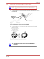
2.9.3
Connecting a Setup Terminal to the GR2000-B
The RS32C cable, across cable having the DUub 9-pin (female) on each end, is
required to connect the GR2000-B to a setup terminal. Connect the RS-232C cable
to the setup terminal in the same way as shown in Figure 2-15 below.
RS-232C Connector
(CONSOLE)
Setup Terminal
RS-232C Cable
RS-232C Connector
(CONSOLE)
Attachment
Screw
9-Pin D-Sub
Connector
Connect the RS-232C cable to the router
Attach cable to the router firmly with screws
Figure 2-15 Connecting a Setup Terminal to the GR2000-B
2.9.4
Connecting the GR2000-B to Other Devices
Connect the GR2000-B to other devices by using interface cables. See the Figure 4-1
as an example.
*
2-12
Note: The required type of cables differs depending on an interface you use. For cable
specificationa and characteristics, see the GR2000-B Installation Guide.
GR2K-GA-0008
Rev. 1.00
Setup Process
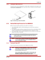
2.9.5
Turning the Power Switch ON
The power switch for the GR2000-B is a rocker switch located next to the power cord
on rear panel. Operate the switch to turn power ON (1) or OFF (0). Turn on the power
at the back of the GR2000-B.
ON
OFF
Power Switch
Figure 2-16 Switching Power ON and OFF
2.10
Normal Start-Up Process for the GR2000-B
Below is the process from powering on the device to starting it.
1. The STATUS RMP indicator starts blinking green as soon as the system is
powered ON.
2. The GR2000-B begins loading it’s software when the ACC (access) indicator lights
in green. During this time, the STATUS RMP indicator continues to blink.
3. The STATUS RMP indicator lights solid green after the software has loaded. The
system then starts up normally.
*
!
2.10.1
Note: The STATUS RMP or STATUS ETHERNET indicator showing red indicates
trouble. For details, see the Hitachi Gigabit Router GR2000 Series Enhanced
Version Operations Guide.
Caution:
If a memory card is not installed, the GR2000-B stops running while showing
"20" in the STATUS CODE display. Power off the GR2000-B and install a
memory card, then power it on again.
Turning the Power OFF
Turn the power switch at the back of the GR2000-B to OFF (0)
!
Caution:
While the access indicator (ACCESS) for a memory card is lit, the memory
card is being accessed. DO NOT pull out a memory card or turn off the
power switch while the memory card is being accessed. If so, you could
permanently damage the memory card.
Some commands require a long time to finish accessing a memory card
when they are executed. Make sure that the access to a memory card is
finished before pulling it out or turning off the power switch.
GR2K-GA-0008
Rev. 1.00
2-13
Hitachi Gigabit Router GR2000-B Series Quick Start Guide
This page left intentionally blank
2-14
GR2K-GA-0008
Rev. 1.00
Chapter 3
Basic Operations
This chapter shows examples of the commands required for connecting the
GR2000-B to other devices. The chapter contains the following sections:
3.1
Configuration examples
Startup of the GR2000-B
Configuration setting
Display of the operation status
Details about the commands introduced in this chapter
More details about the operation
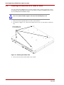
Configuration Examples
Using the example below, this section explains about the simple method of setting
configurations.
Network A
Network B
GR2000-B
Server
Network C
Peer Router
PC
PC
PC
Built-in Ethernet
Port 0
IP 192.168.1.1
PC
Built-in Ethernet
Port
IP 192.168.2.1
Figure 3-1 Example of a GR2000-B Connecting to Other Devices
To construct the configuration above in Figure 3-1, set the GR2000-B according to
the following instructions:
Set IP address "192.168.1.1" for PORT 0 of the GR2000-B built-in Ethernet.
Set IP address "192.168.2.1" for PORT 1 of the GR2000-B built-in Ethernet.
Set IP address "192.168.2.2" for a default route (in case that the IP address
"192.168.2.2" is set for the port of the peer router.)
GR2K-GA-0008
Rev. 1.00
3-1
Hitachi Gigabit Router GR2000-B Series Quick Start Guide
3.2
Startup of the GR2000-B
This section explains about how to start the GR2000-B, login from the setup
terminal, and set the time.
3.2.1
First-Time Login
The default login user name is operator. The default passoword is not set. The
command prompt (>) is shown when you login successfully.
ORJLQRSHUDWRU
$OO5LJKWV5HVHUYHG&RS\ULJKW&+LWDFKL/WG
:HOFRPHWRWKH5RXWHU
FRPPDQG
FRPPDQGFOL
Command prompt is shown after
successful login.
Command mode is switched
to the one similar to those of
the routers used in general
worldwide.
!
*
3.2.2
Input the login user name
operator.
Note: We strongly recommend that you set a password to secure the router. You can
set a password with passwd command.
Setting the Time
You must set the current time the first time you log in. For example, here is how to
set the time to “Sep 7 15:30:00 2002:”
!VHWFDOHQGDU
6DW6HS
!
Use the set calendar command
to set the time. Once executed,
the current time is shown.
The command prompt shows
successful execution.
For showing the current time use the show calendar command:
!VKRZFDOHQGDU
6DW6HS
!
Use the show calendar command to view the time. Once
executed, the current time is
shown.
The command prompt shows
successful execution.
3-2
GR2K-GA-0008
Rev. 1.00
Basic Operations
3.3
Setting the Configuration
This section explains about how to configure the GR2000-B for operation.
(1) The system enters the administrator mode.
!HQDEOH
(2) The system enters the configuration edit mode.
FRQILJXUH
(3) The configuration file is opened.
FRQILJRSHQ
(4) IP address is set for the Ethernet port.
FRQILJOLQH/$1HWKHUQHW
FRQILJOLQH/$1HWKHUQHW
FRQILJLS/$1
(5) A default route is set.
FRQILJLS/$1
FRQILJVWDWLFGHIDXOWJDWHZD\
(6) The information configured is dispayed.
FRQILJVKRZ
OLQH/$1HWKHUQHW
OLQH/$1HWKHUQHW
LS/$1^
The information displayed as a
result of the configuration.
`
LS/$1^
`
VWDWLF^
GHIDXOWJDWHZD\
`
(7) The configuration information is saved.
FRQILJVDYH
(8) The configuration file is closed.
FRQILJFORVH
(9) The system goes out of the configuration edit mode.
FRQILJH[LW
(10) The system goes out of the administrator mode.
H[LW
!
Here is some detailed information about the each of the settings.
3.3.1
Enter the Administrator Mode
!HQDEOH
The system is switched to the
administrator mode by the
enable command.
The # prompt is used in the
administrator mode.
3.3.2
Enter the Configuration Edit Mode (Begin Editing the Configuration)
!FRQILJXUH
FRQILJ
The system is switched to the
configuration edit mode by the
configure command.
The (config)# prompt is shown.
GR2K-GA-0008
Rev. 1.00
3-3
Hitachi Gigabit Router GR2000-B Series Quick Start Guide
3.3.3
Open the Configuration File
FRQILJRSHQ
FRQILJ
*
3.3.4
The configuration file is opened by the open command.
The operative configuration file in memory is opened
in case that the file name was omitted.
Note: his is the example for the case where the operative configuration file in memory
is opened. You can open any designated prepared configuration file by inputting
the file name.
Set an IP Address for the Ethernet Port
FRQILJOLQH/$1HWKHUQHW
FRQILJOLQH/$1HWKHUQHW
Set built-in Ethernet Port 0 of as “LAN0” with the line
command. The "2/0" means that the NIF number is "2"
and the port number is "0" (the built-in Ethernet is commensurate with the NIF number "2”).
FRQILJLS/$1
Likewise, set built-in Ethernet port 1 as "LAN1." The
prompt ! is shown after the configuration changes.
FRQILJLS/$1
Set an IP address and the subnet mask length for
"LAN0" with the ip command. For this example, the IP
address is "192.168.1.1" and the subnet mask length is
"24."
Likewise, set the IP address to "192.168.2.1" and the
subnet mask length to "24" for "LAN1."
3.3.5
Set a Default Route
FRQILJVWDWLFGHIDXOWJDWHZD\
3-4
A static route is set using the static command. In this example, the address
"192.168.2.2" is set as a default route.
GR2K-GA-0008
Rev. 1.00
Basic Operations
3.3.6
Check the Configuration You Set by Displaying its Information
*
Note: Although you can skip this operation, check if the configuration information
edited is correct to avoid the trouble at the time the GR2000-B starts running.
For the display style, refer the examples of each command execution.
FRQILJVKRZ
OLQH/$1HWKHUQHW
OLQH/$1HWKHUQHW
LS/$1^
`
LS/$1^
`
VWDWLF^
GHIDXOWJDWHZD\
`
FRQILJ
3.3.7
*
The "(config)#" prompt is shown
after the information is displayed.
The edited configuration information is saved into the configuration
file you are working on using the save command.
The ! prompt is deleted after the configuration information is saved.
Note: The configuration information is saved into the file currently opened in case that
you skip inputting a file name. Therefore, in this example, the information is
saved into the operative configuration file on memory. You can save the
information into any preparative configuration file designated by inputting a file
name.
Close the Configuration File
FRQILJFORVH
FRQILJ
3.3.9
The information displayed
as a result.
Save the Configuration Information Into the Configuration File
FRQILJVDYH
FRQILJ
3.3.8
The configuration information is
displayed by the show command.
The configuration file being edited is closed by the close command.
Return to the Administrator Mode
FRQILJH[LW
GR2K-GA-0008
Rev. 1.00
The edit is finished using the exit command, and the
system returns to the administrator mode (# prompt).
3-5
Hitachi Gigabit Router GR2000-B Series Quick Start Guide
3.3.10
Exit the Configuration Edit Mode (Finish Editing the Configuration)
The system exits the administrator mode
with the exit command.
H[LW
For the details about each command introduced in this guide, see the following
manuals of the GR2000.
passwd
3-6
User Administration
date
Device Information
admin
User Administration
config
Note:
GR2000 Operations Guide
GR2000 Configuration Guide
Configuration Commands
open
Configuration Subcommand
line
Line Information
ip
IP Information
static
IP Routing Protocol Information
save
Configuration Subcommand
show
Configuration Subcommand
close
Configuration Subcommand
exit
Configuration Subcommand
GR2K-GA-0008
Rev. 1.00
Basic Operations
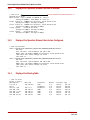
3.4
Display of Operation Status
3.4.1
Display of the Operation Status Covering the Entire Router
!VKRZURXWHU
URXWHU*5%6%>5287(26%@
QRGHQDPH
FRQWDFW
ORFDWH
QRGHLQIRVLPSOH[PRGH
WXQQHORSWLPL]HRII
LSYURXWLQJHQWU\FXUUHQWQXPEHU PD[QXPEHU LSYURXWLQJHQWU\FXUUHQWQXPEHU PD[QXPEHU PDLQIDQDFWLYHQR 0)$10)$10)$1
SRZHUIDQDFWLYHQR 3)$1
SRZHUDFWLYH
67$786503/('JUHHQ
UPDFWLYH
UP,17(51$/
ERRWSRZHURQWLPHVUHVWDUW
ODPS5($'</(' JUHHQ
$/$50/(' OLJKWRII(5525/(' OLJKWRII67$786&2'( OLJKWRII
ERDUG&38 ,QWHO&HOHURQ0+]PHPRU\ .%0%
WHPSHUDWXUH50&38ERDUG QRUPDOGHJUHH
0&SULPDU\VORWPFHQDEOHG
XQNQRZQ*5IRUPDW
.%XVHGXVHU$UHD.%GXPS$UHD.%
.%IUHHXVHU$UHD.%GXPS$UHD.%
.%WRWDOXVHU$UHD.%GXPS$UHD.%
0&VHFRQGDU\VORWPFGLVFRQQHFW
USDFWLYH,17(51$/
PHPRU\VL]H .%0%.%0%XVHG
)L[HGDUHDXVHG .%0%
:$1XVHG .%0%
(WKHUXVHG .%0%
$70XVHG .%0%
,3XQLFDVWXVHG .%0%
,3PXOWLFDVWXVHG .%0%
,3YXQLFDVWXVHG .%0%
,3YPXOWLFDVWXVHG .%0%
!
GR2K-GA-0008
Rev. 1.00
3-7
Hitachi Gigabit Router GR2000-B Series Quick Start Guide
3.4.2
Display of the Operation Status of the Built-In Ethernet
!VKRZQLI
The slot number for the built-in Ethernet is “2.”
1,)DFWLYHSRUW%$6(7%$6(7;UHWU\
$YHUDJH0ESV3HDN0ESVDW
/LQHDFWLYHXS%$6(7;IXOODXWRDF
$YHUDJHRXW0ESV$YHUDJHLQ0ESV
/LQHDFWLYHXS%$6(7;IXOODXWRDF
$YHUDJHRXW0ESV$YHUDJHLQ0ESV
/LQHXQXVHGDF
$YHUDJHRXW0ESV$YHUDJHLQ0ESV
/LQHXQXVHGDF
$YHUDJHRXW0ESV$YHUDJHLQ0ESV
!
3.4.3
Display of the Operation Status of the Interface Configured
!VKRZLSLQWHUIDFH
/$1IODJV H83%52$'&$671275$,/(565811,1*12$5308/7,&$67!
PWX
LQHWEURDGFDVW
1,)/LQH83PHGLD%$6(7;IXOODXWRDF
7LPHVLQFHODVWVWDWXVFKDQJH
/DVWGRZQDW
/$1IODJV H83%52$'&$671275$,/(565811,1*12$5308/7,&$67!
PWX
LQHWEURDGFDVW
1,)/LQH83PHGLD%$6(7;IXOODXWRDF
7LPHVLQFHODVWVWDWXVFKDQJH
/DVWGRZQDW
!
3.4.4
Display of the Routing Table
!VKRZLSURXWH
7RWDOURXWHV
'HVWLQDWLRQ1H[W+RS,QWHUIDFH0HWULF3URWRFRO$JH
/$16WDWLFPV
ORFDOKRVW'LUHFWPV
ORFDOKRVW'LUHFWPV
/$1'LUHFWPV
/$1'LUHFWPV
/$1'LUHFWPV
/$1'LUHFWPV
!
3-8
GR2K-GA-0008
Rev. 1.00
Basic Operations
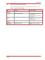
3.5
More Details About Operation
For the details about the operation, see the manuals listed in the Table 3-1 below.
Table 3-1
Details About Other Settings
Item
See Manual
See Section in Manual
Startup/restart of the
GR2000-B
GR2000 Operations Guide
Startup of the operation
Configuration
GR2000 Configuration Guide
•
•
Setting for network
interfaces
GR2000 Configuration Guide
•
•
Setting examples related to the IP
routing protocols
Setting examples related to the IPv6
routing protocols
Setting examples related to the network
interfaces
Setting examples related to the IPv6
network interfaces
Operation of the
GR2000-B
GR2000 Operations Guide
Startup of the operation
Operation of a
operative terminal
GR2000 Operations Guide
Operation overview for an operative
terminal
GR2K-GA-0008
Rev. 1.00
3-9
Hitachi Gigabit Router GR2000-B Series Quick Start Guide
This page left intentionally blank
3-10
GR2K-GA-0008
Rev. 1.00
Chapter 4
Troubleshooting
This chapter explains the troubleshooting required for resolving the troubles related
to the setup of the GR2000-B and it’s basic operations.
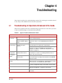
4.1
Troubleshooting for Operations Introduced in this Guide
This section explains about the troubleshooting required for the case where you have
a device malfunctioning or communication problems.
Table 4-1
Types of Trouble and Corrective Action
Type of Trouble
Corrective Action
The Router does It can not be powered.
not start up.
Check if the power cable is correctly inserted or the power
switch is switched to ON (1).
The console is
not functioning.
The router stops
running while
showing "20" for
the "STATUS
CODE".
It stops running while
keeping "STATUS" lighted
in red.
There is a malfunction within the router. See the Regarding the
troubles in the device, see the GR2000 Operations Guide for
details.
Nothing is shown on the
window of the hyper
terminal.
Check to see if the cable is correctly connected. Make sure you are
using a RS-232C cross-cable for the setup terminal.
If a memory card is not
installed into the device.
Turn off power to the router and install a memory card according to
the instructions of section 2.7, “Installing a Memory Card,” on
page 2-8, then turn on the power.
Check if the communication parameters for the software of the
terminal are correctly set. Regarding the communication
parameters, see Table 2-1, “Specifications Required for Setup
Terminals,” on page 2-11.
If a memory card is installed There is the possibility that software is not loaded on a memory
into the device.
card. Install software according to the instructions of the GR2000
Applications Guide.
Communication using built-in Ethernet is not
working.
Check if the cable is correctly connected. For the details about the
cables to be used , see the Chapter 3 "Preparing Iinterface Cables
and the Terminal” of the GR2000-B Installation Guide.
Check if the "LINE" information is correctly set. For the details, see
the section "Configuration setting" of the chapter 4 in this manual.
Check if the routing protocol is set. For the details, see section 3.3,
“Setting the Configuration,” on page 3-3 of this manual.
Check if the IP address of the device connected to the GR2000-B is
set correctly.
GR2K-GA-0008
Rev. 1.00
4-1
Hitachi Gigabit Router GR2000-B Series Quick Start Guide
4.2
More Details About Troubleshooting
See the manuals listed in the Table 4-2 for detailed troubleshooting.
Table 4-2
Troubleshooting and Reference manuals
Item
Reference manuals
Reference sections
Trouble of every kind
GR2000 Operations Guide
Troubleshooting
Details for the operation log
4-2
Log messages
GR2K-GA-0008
Rev. 1.00
Troubleshooting
This page left intentionally blank
GR2K-GA-0008
Rev. 1.00
4-3
Hitachi Gigabit Router GR2000-B Series Quick Start Guide, Part No. GR2K-GA-0008, Rev. 1.00
Copyright © 2002, Hitachi America, Ltd., All rights reserved, Printed in the U.S.A.
Hitachi America, Ltd., 2000 Sierra Point Parkway, Brisbane, CA 94005-1835 U.S.A.